1
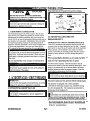
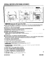
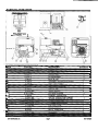
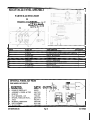
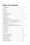
w
m
m
n
w
E
m
:
W I Immm-'w W I E B B "
HEAVY DUTY
GENERATORS
OPERATOR INSTRUCTION MANUAL
A
DANGER
READ INSTRUCTIONS CAREFULLY AND
FOLLOW RULES FOR SAFE OPERATION.
FAILURE TO DO SO COULD RESULT IN
SERIOUS INJURY.
P.O. Box 495
St. Peter, MN 56082
Phone: 507-357-6700
Fax: 507-357-6580
Congratulations on your clzoice of a Winpower heavy duty generator set. You have selected a highquality, precision-engineered generator set designed and tested to give you years of satisfactory portable
service.
To get the best performance from you new engine generator set, it is important that you carefully read
and follow the operating instructions in this manual.
-
Fill out the enclosed warranty information sheet and mail back to us as soon as possible.
Did you know?.....
Winpower offers a very attractive portability wheel kit:
Item PK280 fits ,
the HOV5500VE.
Winpower is your one stop shopping
place for heavy duty generators. We
offer air cooled portables, tractor driven
PTO generators and larger diesel self
contained units. See your dealer for
details or call the factory.
TABLE OF CONTENTS
INTRODUCTION
FEATURES BY MODEL
SAFETY PRECAUTIONS
FUELS AND LUBRICANTS
WATTAGE CALCULATING INSTRUCTIONS
VOLTAGE DROP IN ELECTRIC EXTENSION CORDS
PRESTARTING INFORMATION
TOUBLESHOOTING
GENERAL IDENTIFICATION
PARTS ILLUSTRATION & PARTS LIST
OPTIONAL WHEEL KIT - PK280
'MISCELLANEOUS WATTAGE REQUIREMENTS
Copy you model and serial number here.
No other Winpower generator has the same
serial number as yours. It is important that you
record the number and other vital information
here. If you should ever need to contact us on
this unit it will help us to respond to your
needs faster.
1999 WMPOWER INC
1
1
2
4
4
5
6
7
8
9
10
11
MODEL
SERIAL NUMBER
PURCHASE DATE
DEALER
Page i
HOV SERlES
INTRODUCTION
Thank you for purchasing a WINPOWER generator. This manual covers the operation and maintenance of the HOV Models. It
:ontains the latest product information available at the time of printing. WINPOWER INC. reserves the right to make changes at
.- any time without notice and without incurring any obligation.
WARNING!
A
A
Indicates a possibility that personal injury, equipment damage, or other property damage could occur if the
instructions are not followed.
CAUTION!
Indicates a possibility that personal injury, equipment damage, or other property damage could occur if the
instructions are not followed.
NOTE:
Lists helpful information which should assist you in getting satisfactory performance from your new generator.
If you have a problem with your generator, or have any questions about the generator, consult an authorized Winpower distributor, dealer, or service center. Should you require additional information, please consult the factory service department.
The Winpower generator is designed to give safe and dependable service if operated according to the instructions given in this
manual. Read and understand the owner's operation and service manual before operating the generator. Failure to do so could
result in personal injury or equipment damage.
This manual covers our latest compact portable generator 5000 watt HOV series unit. Winpower builds four different model
types -EL, HOV, COV & CHD series. All use the same heavy-duty generator designs, but are offered with various engines and
differing levels of features. This manual is for the HOV model only. The description and features are listed in the following
paragraphs.
The most basic model group is the EL Series. The EL series is designed to provide a heavy-duty generator set with essential
features but avoiding the cost of unused features. Primary applications for the EL series are for infrequent or medium duty loads
where the initial cost is critical and unit will be operated less than 50 to 100 hours per year. Typical uses might be for farm, ranch
or home standby or portable field power away from convenient utility or where running an extension cord is impractical. The EL
Series have premium engines, but use their manufacturers entry level offerings to minimize cost.
L
The HOV5000VE is the Premium Featured model that has a heavy duty generator. The shock isolated receptacle panel and
premium OHV engine basic receptacle panel includes a 15120 Amp GFCI (Ground Fault Circuit Interrupter) and a 30 Amp,
1201240 Volt, Cwire Twist lock receptacle. Both are protected with 2 individual circuit breakers. The OHV (Overhead Valve)
engine has a low lubricating oil safety shutdown feature. This unit is designed for regular, rugged, heavy, and severe loads and
operating conditions. Each unit is crafted for the construction and rental markets where the added cost of the premium engine is
offset by the increased reliability and efficiency of the generator sets' ability to stay on the job to completion..... day in and day
out.
The CHD line is "Commercial Heavy Duty". Kohler Command Series engine features full pressure lubricaton with spin on oil
filter. Overhead valve engine assures reliable starting, cooler running, and less vibration. Electric Start and low oil shutdown are
standard on this model.
The COV line is the Premium Featured model group that has the same heavy duty generators, but includes a full control panel
with features like Econ-O-Mizer auto idle, Dual Voltage, Switchable Full Power, Twist lock receptacles, 4-wire receptacles and
premium engine offerings. These units are designed for regular, rugged, heavy, and severe loads and operating conditions. These
units are also made to serve faithfully in the construction and rental markets where the added cost of the heavy duty features are
offset by the increased convenience, reliability and reduced noise & wear on engine.
MODEL FEATURES
MODEL
ENGINE
FUEL
LUBE
START
WATTS
AMPS@
MFRIMODEL H P
TANK
OIL**
TYPE MAX / RATED 120/240V FEATURES*
HOV5000VE
VANGUARD
9.0
18.0 QT
2.4 PTS
RECOIL
5000 14500 37.5 1 18.8
1,2L, 3,4
** LUBE OIL -CAPACITY
LISTED FOR CONVENIENCE ONLY - USE ENGINE MFRS RECOMMENDATION
*FEATURES - LISTED BELOW BY REFERENCE NUMBER WITH EXPLANATION 1. Full protective 'roll cage' carrying frame
2. Low lubricating oil shutdown (lube oil Level or Pressure)
3. Overhead valve, cast iron sleeved engine
4. Extended run, frame mounted fuel tank - shock isolated
1999 WMPOWER INC
Page 1
HOV SERIES
SAFETY PRECAUTIONS
to release any pressure which may have formed in the fuel
tank. Return the generator to its original location before
restarting the engine.
LEARN GENERATOR SAFETY
Improper use of maintenance can result in injury.
Carefully read this manual. Learn how to operate your
generator correctly. Also pay attention to point of use safety
messages in this manual.
A
-
OPERATE ENGINE SAFELY
DO NOT RUN ENGINE in an enclosed or poorly ventilated
area (inside a room, garage, barn, etc.) Exhaust gas contains
carbon monoxide, an odorless and deadly poison.
DO NOT TOUCH HOT ENGINE OR MUFFLER.
DANGER
UNAUTHORIZED MODIFICATIONS TO THE GENERATOR MAY IMPAIR THE FUNCTION AND/OR SAFETY
AND AFFECT MACHINE LIFE. USE ONLY APPROVED
ACCESSORIES ON THE GENERATOR.
DO NOT let any one operate the generator without proper
instruction.
PROTECT PEOPLE AND PETS
KEEP PEOPLE AND PETS OUT OF THE AREA where
you are using the generator.
DO NOT let children operate the generator, or handle
electrical power cords.
OBEY ALL FIRE SAFETY REGULATIONS.
Fire prevention regulations of the U.S. Forestry jurisdiction
require approved spark arrestor screen to be installed on
gasoline powered products used on U.S. Forestry forests,
brush and grasslands.
Your unit is not equipped with a spark arrestor muffler. See
engine manufacturer for USDA Forestry approved spark
arrestor kit and added maintenance instructions.
Compliance with local, state and federal laws is the user's
responsibility. Replacement spark arrestor screen kits are
available for you generator from the engine dealer. If you
have any questions concerning spark arrestor screens or
there use, please contact your Winpower servicing dealer.
OPERATION OF GENERATOR should be restricted to
mature, properly instructed individuals.
OPERATE GENERATOR SAFELY
HANDLE FUEL SAFELY - AVOID FIRES
DO NOT ATTEMPT TO CARRY GENERATOR when
engine is running.
DO NOT USE ANY OTHER FUEL than that recommended
in your engine manufacturer's Operator's Manual. Handle
gasoline with care: it is highly flammable. Use an approved
gasoline container.
DO NOT OPERATE GENERATOR ON AN INCLINE. It
should be placed on a fm, dry, level surface for proper
engine operation an lubrication. Keep the area free of any
flammable material such as leaves, brush or fuels.
-
FILL THE FUEL TANK OUTDOORS.
DO NOT OVERFILL FUEL TANK.
DO NOT SMOKE while you fill fuel tank or service fuel
system.
DO NOT REMOVE GAS CAP OR ADD GASOLINE to
tank if engine is hot or running.
CLEAN UP spilled gasoline.
AVOID ACCIDENTAL FIRES AND ENGINE
OVERHEATING.
DO NOT AIM ENGINE EXHAUST AT MATERIALS
THAT COULD CATCH FIRE.
FACE COOLING AIR INTAKE (RECOIL START
AREA) AND MUFFLER SIDE OF ENGINE 6.6 FT.
2 M (OR TWO METERS) AWAY FROM BUILDINGS,
OBSTRUCTIONS AND OTHER BURNABLE OBJECTS.
MOVE AWAY from refueling area before attempting to start
generator engine.
KEEP ENGINE CLEAN. Remove grass, leaves, excess oil
and dirt before you start engine.
LET ENGINE COOL before you store generator in a
building.
DO NOT store generator where fuel fumes could reach and
open flame or spark.
Drain gasoline before transporting generator.
REFUEL IN A SAFE PLACE. Move the generator at least
10 feet from its operating location. Open the fuel cap slowly
1999 WINPOWER INC
Page 2
I
I
HOV SERIES
SAFETY PRECAUTIONS
A
DANGER
DO NOT OPERATE GENERATOR IN AREA OF FLAMMABLE MATERIALS.
DO NOT ENCLOSE UNIT. IT RELIES ON FREE AIR
CIRCULATION TO COOL THE ENGINE AND GENERATOR. ENCLOSING THE UNIT CAN CREATE A FIRE
HAZARD RESULTING FROM ENTRAPPED GAS
FUMES AND OVER-HEATING WHICH CAN RESULT
IN DAMAGE TO THE ENGINE AND OTHER COMPONENTS.
THESE GENERATORS ARE NOT INTENDED FOR
INSTALLATION IN RV'S (RECREATIONAL VEHICLES), BOATS OR SIMILAR LOCATIONS.
RESPECT ELECTRICITY
DO NOT TOUCH ELECTRICAL EQUIPMENT while
standing on metal floors, damp concrete, or other wellgrounded surfaces.
DO NOT HANDLE ELECTRICAL EQUIPMENT while
wearing damp clothing (particularly wet shoes) or while skin
surfaces are damp.
-
DO NOT, under any circumstances, connect your generator to
any circuit or receptacle receiving electrical power (home,
office, etc.) from any other sources as this is likely to result in
a fire and damage all electrical systems.
DO NOT, under any circumstances, use the generator for any
purpose that exceeds its rated capacity.
GROUND THE GENERATOR. The manufacturer has
provided a grounding lug for the proper grounding of the
generator. Manufacturer does not supply the required
grounding conductor or grounding electrode because it would
be impossible to cover every exception and meet all local
code requirements for the proper grounding governing the use
of your generator.
IF CONSIDERING CONNECTING GENERATOR to
power existing wiring systems (house, barn, pumps, for
example), CONTACT A LICENSED ELECTRICIAN to
ensure proper, safe connection through an approved isolation
switch and in compliance with local electrical, fire safety and
building codes.
INSPECT GENERATOR CAREFULLY
INSPECT THE GENERATOR CAREFULLY before you
operate it.
BE EXTRA CAUTIOUS WHEN WORKING with generator during wet weather. Generators are not waterproofed.
Using a generator in a wet place or during stormy weather
could result in short circuits, electric shock or electrocution.
GUARDS AND SHIELDS must be in place.
DO NOT pour water directly over the generator, nor wash it
with water.
DO NOT operate the generator without an air filter. Rapid
engine wear will result.
DO NOT operate equipment when mentally or physically
stressed.
DO NOT operate the generator if the oil level is low.
DO NOT WORK on ungrounded electrical equipment.
DO NOT CONNECT GENERATOR DIRECTLY to house
hold electrical circuits.
KEEP NUTS, BOLTS, AND SCREWS TIGHT. Loose
parts may result in personal injury or damage to the unit.
VENTILATING OPENINGS such as the generator cover,
air filter and muffler exhaust outlet must be cleaned periodically and kept free of debris to ensure proper operation and
adequate cooling of the generator.
DO NOT USE ungrounded extension cords.
SERVICE GENERATOR SAFELY
NEVER ALTER CORD, or plug of any appliance to be used
with generator.
KEEP generator clean.
BEFORE you service or remove parts, let the engine cool.
A
DO NOT work on generator while it is being operated.
THESE UNITS PRODUCE 120V AND 240V WHICH MAY
CAUSE FATAL ELECTRICAL SHOCK IF PRECAUTIONS
ARE NOT FOLLOWED.
USE ONLY POWER CORDS that are suitable for use
outdoors and are so marked. Always examine power cords
for signs of fraying, damage or cracks in the insulation before
using them.
L
DO NOT HANDLE POWER CORDS that have damaged
insulation or are wet.
1999 WINPOWER INC
Page 3
DO NOT adjust generator when engine is running, unless the
procedure is approved. STOP THE ENGINE.
USE ONLY identical replacement parts when servicing unit.
DO NOT ALTER EXHAUST SYSTEM. Use only Engine
Manufacturer approved exhaust mufflers.
DO NOT ALTER ENGINE SETTINGS. The engine speed
is controlled by a preset governor to deliver rated electrical
frequency (60 HZ). Consult you Winpower servicing dealer if
in doubt.
HOV SERIES
STORE GENERATOR SAFELY
SAFETY PRECAUTIONS
WHEN TRANSPORTING your generator, make sure it is in
an upright position and that el v4ve is off and gasoline is
not leaking. Secure it from sliding.
Before you leave the generator unattended:
1. Stop the engine by moving the Engine Ignition Switch
to the OFF position.
2. Turn fuel valve to OFF position.
3. Disconnect spark plug wire.
4. Do not store generator where fuel fumes could reach
an open flame or spark.
HAVE A FIRE EXTINGUISHER NEARBY
Have a multipurpose dry chemical fue extinguisher filled and
handy. Know how to use it.
COMPLY WITH ALL FIRE PREVENTION REGULATIONS. We recommend you keep a fire extinguisher and
long-handle shovel close by whenever using a generator in
area where dry grass, leaves or other flammable materials are
present.
WHEN NOT IN USE, STORE GENERATOR in a cool,
dry place and AWAY FROM POSSIBLE SOURCES of
ignition such as gas water heaters, furnaces, clothes dryers,
etc.
ENGINE OIL
-
FUELS AND LUBRICANTS
FUEL
L
IMPORTANT
Before starting engine for fust time, add oil, as unit is
shipped dry.
A
DANGER
HANDLE FUEL CAREFULLY. IF THE ENGINE IS
HOT OR RUNNING, DO NOT FILL THE FUEL TANK.
DO NOT SMOKE WHILE YOU FILL THE FUEL TANK
OR SERVICE THE FUEL SYSTEM.
IMPORTANT
Operating a generator with a low oil level will cause
serious engine damage.
See engine manufacturer's Operator's Manual for all engine operating and maintenance requirements.
WATTAGE CALCULATING INSTRUCTIONS
IMPORTANT
Do not exceed rated capacity of your generator. Serious
damage to the generator or appliance can result from
overload.
2. Use actual listed values from the motor label if available.
If only one value is shown that value is the running voltlarnps.
Determine the approximate starting wattage requirement by
multiplying the calculated wattage by 3 times for most motor
types-to assure adequate
capacity. If no label
information is available use the values in the following chart
as a guide.
1. When matching generator wattage capacity to tool or
appliance operation, starting and running wattage requirements should be calculated to insure the generator is not
overloaded.
2. Two types of electrical appliances may be powered by
your generator.
a. "Resistive Load Appliances" (i.e., lights, heaters,
television sets, radios) starting wattage and
running wattage requirements are the same.
b. "Inductive Load Appliance" (i.e., electric motors
and hand held power tools) starting wattage may
be 1.5 to 3.5 times greater than the running or
operating wattage requirements.
CALCULATING WATTAGE REQUIREMENTS
Before operating the generator list all the appliances andlor
tools you intend to operate at the same time. Then determine
starting requirements and running wattage requirements.
1. Some tools and appliances will list on the motor label
starting and running voltage and amperage requirements.
Refer to the starting volts and amps shown on the label. To
convert this information to wattage use the following formula:
Volts x Amps = Watts
Ex. (Starting voltage and amperage for 114 hp drill)
120V x 10 Amps = 1200 Watts
1999 WMPOWER M C
Page 4
_
WATTS REQUIRED TO START MOTOR
Motor
Size Running
Repulsion
Capacitor Split
(HP)
Watts
Induction
Phase
1I6
275
600
850
2050
1I4
400
850
1050
2400
113
450
975
1350
2700
112
600
1300
1800
3600
314
850
1900
2600
-1
1100
2500
3300
--
3. The starting wattage required by resistive loads is the same
as running wattage and is usually listed in watts on the label.
e.g. 60 watt light bulb
CALCULATING RUNNING WATTAGE
REQUIREMENTS
1 . Running wattage requirements are calculated the same as
starting wattage. Refer to the running or operating volts and
amps referenced on the motor label and calculate watts by
multiplying Volts and Amps.
HOV SEFUES
-
WATTAGE CALCULATING INSTRUCTIONS
-
CALCULATING TOTAL WATTAGE
REQUIREMENTS
Generator capacity must be equal to or exceed total starting
and running wattage load.
1. To determine total wattage load, list all appliances that
may be operated by the generator at the same time.
2. List running wattage requirements of appliances that will
operate in constant application.
If generator capacities are not adequate to cover all requirements, deduct the least needed appliance so generator can be
used without overloading.
If requirements are mandatory and cannot be reduced, obtain a
larger capacity generator.
GENERATOR CAPACITY CHART
Continuous
Maximum
Model
Running
Wattage
HOV5000VE
GENERATOR APPLICATION WORKSHEET
Requirements
Running
Starting
Total
Wattage
Wattage
Wattage
Furnace "118" HP
300
500
500
Lights
60
60
60
80
80
80
Radio
255
255
255
TV
895
TOTAL
3. List starting wattage requirements of appliances that may
cycle on and off.
4. Compare the running and starting wattage requirements for
each appliance, and list the larger wattage requirement in
the column TOTAL WATTAGE.
5. Add the total wattage requirements for all appliances to
determine the maximum generator load.
L
In the above example running and starting wattages for lights,
radio and T.V. are the same values. However, the starting
wattage for the furnace, which will cycle on and off, is greater
than the running wattage. Therefore, total wattage load on the
generator will equal the furnace starting wattage of 500 watts
plus the running wattages of the lights, radio and T.V., a total
of 895 watts, as shown in the TOTAL WATTAGE column.
6. Using figures calculated, use chart to compare requirements to generator capacity.
EXTENSION CORD USAGE
When using a tool at a considerable distance from power
source, a 3-conductor, grounding type extension cord of
adequate size must be used for safety, and to prevent loss of
power and overheating. Use the following table to determine
the minimum wire size required.
1
Use only three wire extension cords with a three-prong
grounding type plug and three-pole receptacles which
accept the tool's plug. Replace or repair damaged cords
immediately.
IMPORTANT
A cord that is hot to touch is overloaded.
WIRE GAUGE CHART
EXTENSION
12OVl24OV
CABLE LENGTH
*Gauge
25 Ft. (7.62 M)
10
10
50 Ft. (15.24 M)
75 Ft. (22.86 M)
10
8
100 Ft. (30.48 M)
8
150 Ft. (45.27 M)
8
200 Ft. (60.94 M)
*American Wire Gauge Size
VOLTAGE DROP IN ELECTRIC EXTENSION CORDS
When a long electric cord is used to connect an appliance or tool to the generator a certain amount of voltage drop occurs in the
extension cord which lessens the effective voltage available to the appliance or tool. The chart below has been prepared to
illustrate the approximate voltage loss when an extension cord of 300 feet (approx. 100 meters) is used to connect an appliance or
tool to the generator.
Nominal A.W.G.
Allowable
No. of
Cross
Current StrandsJStrand Resistance
Gauge
Current Amp.
Dia.
Section
No.
mm3
No./mm
Ohms/lOOm 1A
3A
5A
8A
10A 12A
15A
A
No.
0.75
3010.18
2.477
2.5V 8V
12.5V
18
7
1.27
12
5010.18
1.486
1.5V 5V
7.5V 12V
15V 18V
16
2.0
3710.26
14
5V
1OV 12V
1V
3V
8V
15V
17
0.952
1.5V 2.5V 4V
5V
23
4510.32
0.517
3.5
12-10
6.5V
7.5V
1V
7010.32
5.5
2V
2.5V 3.5V 4V
5V
35
0.332
10-8
-
L
MAXIMUM OUTPUT OPERATION
Limit operation of the generator at maximum output to 3 minutes. Additional 3 minute periods of maximum output are possible
if the generator is allowed 10 minutes to cool between periods of maximum output. Cool engine by operating in the throttle
position with the output load disconnected.
1999 WMPOWER INC
Page 5
HOV SERIES
PRESTARTING INFORMATION
A
-
Plug connections to all equipment should be as follows:
DANGER
!
DO NOT RUN ENGINE IN AN ENCLOSED AREA.
EXHAUST GAS CONTAINS CARBON MONOXIDE, AN
ODORLESS AND DEADLY POISON.
.-4
.
L
'-
Ground C
1
li>/;~3~;
r\
".
-
-
" !
-
IMPORTANT
Do not start engine with AC loads connected. Damage to
the generator or appliance may result.
I
Hot-utral
-
a
!
-
:
V
sqs.;v:
1. GROUNDING GENERATOR
The National Electrical Code (NEC) requires that all separately derived AC systems be grounded per Article 250-26.
Manufacturer has added a grounding lug type terminal per
Article 250-26 (a) from the noncurrent-carrying metal parts to
the conductor to be grounded. Manufacturer does not supply
the required grounding conductor or grounding electrode
because it would be impossible to cover every exception and
all local code requirements. See your local codes and the
NEC manual for the proper grounding for your application.
NOTE
As a general rule, do not use electrical equipment in wet or
damp areas. Additional rules from NEC, OSHA and state
codes apply to portable generators when used on construction sites.
It is the responsibility of the consumer to meet the above
requirements.
Location o f grounding lug type terminal
AC RECEPTACLESICIRCUIT
BREAKERIGFCI
GROUND FAULT CIRCUIT INTERRUPTER (GFCI)
These GFCI outlets provide protection against ground fault
currents which can cause shocks that may be fatal. A ground
fault current is caused by an AC system with faulty insulation.
When a person uses the defective AC system, and if that
person is contacting an electrical ground, then stray current
caused by faulty insulation will flow through the person's
body.
When a ground fault is detected in an AC system, the GFCI
outlet will "trip" and interrupt the flow of current.
Test both outlets regularly. Push the test button and all
current to the outlets on that line should be interrupted. If the
power is not interrupted, do not use the outlets, and have a
qualified technician make the necessary repairs. Press the
reset button to restore power to all the outlets.
IMPORTANT
The generator must be placed on a fm, level surface for
proper lubrication of the engine.
2. AC RECEPTACLES 1 CIRCUIT BREAKER
IMPORTANT
Do not exceed maximum rated capacity of your generator,
as serious damage to the generator or appliance could result.
Disconnect appliances from generator before starting engine.
IMPORTANT
Do not exceed rated capacity of your generator, as serious
damage to the generator or appliance is connected.
The generator is equipped with a frame grounded
120V(GFCI) 15/20 amp receptacle (A), 1201240V 30 amp
four hole receptacle (B). The receptacles are protected by
button-type circuit breakers (C).
IMPORTANT
Note receptacle wiring polarity to prevent equipment or
generator failure.
Circuit breakers trip automatically under circuit overload.
When a circuit breaker trips, determine the cause. Typical
If a circuit breaker trips, locate and correct the problem, and
allow circuit breaker to cool for 1 minute. Then reset circuit
breaker by pushing button in.
1999 WINPOWER INC
.-
Page 6
HOV SERIES
-
4. OPERATING GENERATOR / AC OUTPUT
5 . Connect equipment to generator receptacle.
1. Make sure all power tools, extension cords, appliances are
-
6. FREQUENCY (Hz)
disconnected from the generator.
2. Check that equipment switches are in the "OFF" position.
3. Start engine (See Engine Operator's Manual).
Do not plug in extension cords to'generator receptacles or
attempt to operate electrical tools or appliances when engine
is operating at idle or intermediate speed positions, as
damage to generator or appliance could result.
Your generator has been factory preset to 60 cycles (one Hertz
(Hz) equals one cyclelper second, the same as 120 volt
household current) at 3600 rpm with throttle in FULL
position, under load.
The 60 cycle output is the standard electrical frequency for the
United States.
NOTE
Adjustment or changing of frequency should only be made
by authorized servicing dealer.
4. Allow the engine to warm up 2 - 3 minutes before
connecting tools or appliances.
TROUBLESHOOTING
SYMPTOM
Engine does not start
POSSIBLE CAUSE
1. Ignition switch off
2. Fuel valve off
3. Low on fuel or oil
4. Unit loaded during start-up
5. Faulty spark plug
6. Loose wire
No electrical output
1.
Repeated circuit breaker
tripping
CORRECTIVE ACTION
1. Turn to "ON" position
2. Turn to "ON" position
3. Add fuel or oil
4. Remove load
5. Replace
6. Inspect & repair
Circuit breaker
1.
2. Faulty receptacle
3. Tripped G.F.C.I.
4. Faulty power cord
2.
3.
4.
a] Tripped - Depress and Reset
b) Defective - Replace
Replace
Reset or replace if defective
Inspect & replace
1. Overload
2. Faulty equipment or cords
1.
2.
Reduce load
Check for bare wires or frayed insulation on equipment
When the engine will not start:
1 . Is there enough fuel?
2. Is the fuel valve on?
3. Is gasoline reaching the carburetor? To check, loosen the carburetor float bowl drain plug with the fuel valve on.
4. Is the engine ignition switch " O N ?
-
5. Is there enough oil in the engine? Oil level must be at full mark for each start see engine manual.
6. Is the choke lever in its proper position?
-
7. Is there a spark at the spark plug?
a) Remove the spark plug cap. Clean any dirt from around the spark plug base, then remove the spark plug.
b) Install the spark plug in the plug cap.
c) Turn the erfgine switch on.
d) Ground the side electrode of the spark plug to any engine ground, pull the recoil starter to see if sparks jump across the gap.
e) If there are no sparks, replace the spark plug. If OK, try to start the engine according to the instructions.
8. If the engine still does not start, take your generator set to the nearest engine dealer
1999 WINPOWER INC
Page 7
HOV SERIES
GENERAL IDENTIFICATION MODEL HOV5000VE
I
1
1.
Ignition Switch - Switch to left is "OFF" -right is "ON" or "RUN"
2.
120V / 15/20 AMP Duplex G.F.C.I. Receptacle opens (Stops electricity) when a short occurs between the electric tool and
ground path to the generator to protect the operator. To rest the G.F.C.I., wait one minute and depress reset button.
3.
1201240 V.A.C. 4 Hole Twist Lock Receptacle.
4.
Grounding Lug - Attachment point for adding a ground strap to an external earth ground.
5.
HandleITube Frame - Protective carrying frame for generator.
1.
6. Receptacle Panel - Contains wiring for receptacles, circuit breaker and control switches.
7. Muffler - Refer to engine Operator's Manual for maintenance.
Optional Forestry Service approved Spark Arrestor - Prevents hot exhaust particles from exiting the engine (available from
engine dealer).
8. Fuel Shut Off Valve - Turn clockwise to shut off fuel after shutdown.
-
9. AC Circuit Breakers (20 amp) Protects receptacles and generator winding fiom overload. Breaker button pushed in allows
electricity flow to receptacles. Breaker button out (tripped) prevents electricity flow to receptacles.
10. Fuel Tank Cap - Covers and seals fuel tank.
11. Fuel Tank - Four and one half (4.5) gallon capacity.
-
12. Generator Housing Houses electricity generating components.
13. Generator Vents - Provides cooling air flow for electricity generating components.
DO NOT BLOCK.
-
14. Oil Filler Cap / Dipstick Access cap for adding or replacing engine oil. Refer the engine Operator's Manual for
maintenance intervals.
15. Generator Mounts - Reduces engine vibration to the frame.
16. Fuel filter - See engine manual for maintenance/replacement.
17. Air Cleaner - See engine manual for maintenance/replacement.
-
18. Spark plug - See engine manual for maintenance/replacement.
19. Recoil handle - See engine manual for maintenance/replacement.
1999 WMPOWER M C
Page 8
HOV SERIES
.
PARTS ILLUSTRATION
CONNECTION DIAGRAM
r------R*m
------.-(
DETAIL "A"
FROM RECEPTACLE
PANEL
-
ITEM
1
2
3
4
1 5
6
7
8
9
10
12
\*
1
14
15
16
17
18
19
20
1999 WINPOWER INC
I
-
-
-
-
-
PART NO.
A-300226
B-300043-7
A-3002 13
A-3002 14
DESCRIPTION
ENGrNE
GENERATOR
CRADLE, END
CROSSMEMBER
A-300225
A-3002 15
A-3002 16
A-300200
A-30022 1
A-64062-000
A-16133-000
A-300222
A-62825-003
A-62825-00 1
B-64024-000
A-1 5482-000
A-300230
B-30030 1
A-239 17-000
A-9877 1-000
BACK PLATE
ASSEMBLY, RECEPTACLE PANEL
SIDE, LEFT CRADLE
SUPPORT, FUEL TANK
BAFFLE, AIR
SHOCK MOUNT
LEATHER WASHER
SUPPORT, GENERATOR
SPACER GENERATOR SUPPORT
SPACER, THRU BOLT
4.5 GALLON FUEL TANK
CAP, FUEL TANK
COVER, ENGINE
DECAL, POWR-PAK
GROMMET
FUEL SHUT OFF VALVE
Page 9
QUANTITY
1
1
2
2
2
1
1
1
1
6
2
1
I
I
1
I
1
1
1
1
2
1
1
I
HOV SERIES
RECEPTACLE PANEL ASSEMBLY
PARTS ILLUSTRATION
&
WIRING DIAGRAM
cog+r;kr k i t
fiac*ucC-S
b a
A
ITEM
1
2
3
14
PART NO.
A-3002 17
A-3002 18
A-64045-009
A-642 11-000
DESCRIPTION
QUANTITY
SIDE, RIGHT CRADLE
1
COVER, RECEPTACLE PANEL (NOT SHOWN) 1
STRAP, MOUNTING
2
GROUND LUG
1
I5
6
7
8
9 1286-00 1
15147-001
A-97360-000
A-64045-0 16
CIRCUIT BREAKER
RECEPTACLE, GFCI (20 AMP)
RECEPTACLE
STRAP, MOUNTING
2
1
1
1
r-
I
OPTIONAL WHEEL KIT PIC280
FOR MODEL HOV5500VE
1
2
3
4
5
6
7
8
9
10
DESCRIPTION
SUPPORT AXLE
HANDLE, WHEEL KIT
ASSEMBLY, WHEEL & TIRE
HUBCAP
FLAT WASHER, 1 318
SPACER, TUBULAR SPLITpAXLE
BUSHING, THREADED
FOOT, RUBBER
PLUG, TUBE
1999 WMPOWER M C
PART NO.
300224
300223
43657-001
64327-000
1178-000
62825-009
64326-011
16072-000
20191-000
15511-000
QUANTITY
2
2
2
2
5
1
1
2
2
1
Page 10
HOV SERIES
MISCELLANEOUS WATTAGE REQUIREMENTS
-
REQUIREMENTS
Air Condition, Central
20,000 BTU
24,000 BTU
TOTAL Inductive
Starting Watts
REQUIREMENTS
Furnace Fan (Gas or Fuel Oil)
118 HP
1/6 HP
114 HP
113 HP
5,800
8,750
Blanket, Electric*
Charger, Battery*
4 amp
10 amp
15 amp
30 amp wI200 amp boost
60 amp wI250 amp boost
-
Grinder, Bench
6 inch
8 inch
90
200
3 80
65013,600
1,50015,750
Cleaner, Grain
114 HP
1.650
Coffee Maker*
1,750
Compressor, Air
112 HP
1 HP
3,000
6,000
TOTAL Inductive
Starting Watts
Heater, Portable Space
(Kerosene, Diesel Fuel)
30,000 BTU
50.000 BTU
I
800
1.OOO
90,000 BTU
150,000 BTU
350,000 BTU
I
1,720
3,900
Iron*
1;625
2,125
1,200
Conveyor, Portable
112 HP
3,400
Light Bulbs*
Cooler, Milk
2,900
Cultivator, Electric
2,100
Dehumidifier
1,450
Light, Flood
HID
Metal Halide
Mercury Vapor
(not recommended)
Sodium Vapor
1,250
De-Icer, Stock Tank*
1,000
Milker 3-1/2 cu. ft. (112 HP)
3,300
Mixer (Vacuum Pump) (2 HP)
10,500
Mixer, 55 gal. drum (114 HP)
1,900
Motors, Farm Duty
Standard (e.g. conveyor,
feed auger, air compressor)
113 HP
112 HP
314 HP
1,720
2,575
4,500
4,400
High Torque (e.g. Barn leaners,
silo unloaders, silo hoists, bunk
feeders)
1-112 HP
8,100
1,300
Motors, Industrial Duty Split Phase
118 HP
116 HP
114 HP
1/3 HP
800
1,225
1,600
2,100
Dish Washer
Cool dry
Hot dry
Drill, Hand
114 inch
318 inch
112 inch
Dryer, Clothes
Gas
Electric
Dryer, Hair
Elevator, Grain (314 HP)
2,100
1,000
350
400
800
2,500
7,550
300 - 1,200
Fence, Electric* (25 mile)
Fry Pan, Electric
Indicated on bulb
125
3 13
--
L
*These are resistive loads in which starting wattage requirements do not exist.
1999 WINPOWER INC
Page 11
HOV SERIES
MISCELLANEOUS WATTAGE REQUIREMENTS (CONT.)
REQUIREMENTS
Capacitor Start, Induction Run
113 HP
112 HP
314 HP
Capacitor Start, Capacitor Run
1-112 HP
TOTAL Inductive
Starting Watts
2,020
3,075
4,500
8,100
Fan Duty
118 HP
116 HP
114 HP
113 HP
112 HP
1,000
1,400
1,850
2,400
3,500
REQUIREMENTS
TOTAL Inductive
Starting Watts
Electric Chain Saw
12 inch, 1-112 HP
14 inch, 2 HP
900
1,100
Table Saw
9 inch
10 inch
4,500
6,300
Television*
Color
Black and White
300
100
Toaster*
2 slice
4 slice
1,050
1,625
Trimmer, Hedge 18 inch
400
Trimmer, Nylon Line
Standard 9 inch
Heavy Duty 12 inch
350
500
Vacuum Cleaner
Standard
Deluxe
800
1,100
Vacuum, Wet & Dry
1.7 HP
2.5 HP
900
1,300
2,100
3,200
Washer, Clothes
3,450
2,150
3,100
Washer, High-pressure
518 HP
Opener, Garage Door
114 HP
113 HP
1,100
1,400
Oven, Microwave (625 watt)
2,800
Polisher, Floor
16 inch - 314 HP
20 inch - 1 HP
4,500
6,100
Pumps
Centrifugal, 900 GHP
Submersible, 400 GPH
sump
113 HP
112 HP
Wet
113 HP
112 HP
900
600
1 HP
1-112 HP
50 - 200
Radio*
Refrigerator
Welder*
2,900
70 amp
100 amp
200 amp
Saws
Blank, 14 inch
Circular,
6- 112 inch
7-114 inch
8-114 inch
4,600
9,050
10,310
2,500
2,000
3,600
9,000
500
900
1,400
IMPORTANT
There are examples of appliances in this chart that are more than rated generator capacities. They are shown for reference data
only. The running and additional inductive starting wattage shown in this chart are approximations. Actual wattage can usually
be found on light bulbs or appliance name plate. If not, determine wattage by multiplying listed amperage by voltage.
*These are resistive loads in which starting wattage requirements do not exist.
1999 WINPOWER M C
Page 12
HOV SERIES