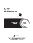
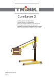
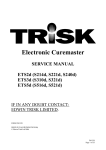
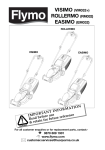
1
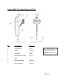
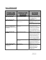
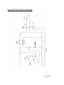
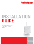
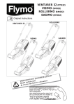
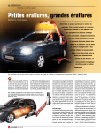
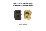
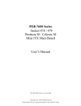
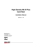
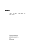
HOTSPOT
HSO4, HTO4
SERVICE MANUAL
USA
Page 1 of 15
Form Fm 350
IMPORTANT
1.
ISOLATE MAINS SUPPLY BEFORE REMOVING COVERS.
2.
THIS MANUAL IS AN UNCONTROLLED DOCUMENT. TRISK RESERVE THE
RIGHT TO UPDATE UNIT SPECIFICATIONS WITHOUT PRIOR NOTICE OR
CONSULTATION.
3.
PLEASE READ THE RELEVANT REPAIR PROCEDURE THOROUGHLY
BEFORE COMMENCING ANY SERVICE OPERATION
4.
SERVICING OPERATIONS SHOULD ONLY BE CARRIED OUT BY QUALIFIED
SERVICE PERSONNEL WHO MUST USE TRISK APPROVED COMPONENTS.
5
THE HAND HELD UNIT (HH04) IS ONLY SUPPLIED FOR SALE IN THE U.S.A.
WITH A STAND OR TIMER STAND, NOT AS A SEPARATE ITEM - DUE TO UL
APPROVAL REQUIREMENTS.
6
THIS UNIT MUST NOT BE OPERATED WITHIN 10 Ft. OF SPRAYING
OPERATIONS.
Page 2 of 15
Form Fm 350
CONTENTS
Warnings.
2
Introduction
4
Servicing Tools
4
Service Diagrams
Hotspot Handheld
Hotspot with Timer Stand
Hotspot with Stand
Timer Box Diagram
Fault Finding Guide
5
6
7
8
9
Repair Procedures
Procedure 1:
Procedure 2:
Procedure 3:
Procedure 4:
Procedure 5:
Procedure 6:
Procedure 7:
Procedure 8:
Circuit Diagram
Handle Removal
Mains Cable Replacement
Switch Replacement
Timer Replacement
Relay Replacement
Socket Replacement
Mains Cable Replacement
IR Emitter Replacement
10
10
11
11
12
12
12
13
15
Page 3 of 15
Form Fm 350
INTRODUCTION
There are two versions of the Trisk Hotspot designed for the market –HSO4 and HT04:
HSO4 is a Hotspot unit complete with a quick release stand
HTO4 is a Hotspot unit complete with a quick release stand and timer box
This manual is designed for the servicing of both of these units. Please note that
Hotspot part references in this manual refer solely to the parts for the Hotspot units
which are not compatible with parts available for other Trisk units.
The absolute minimum tools required for servicing the Hotspot range include:
Quantity
Tool
2
1
1
1
1
1
1
1
1
1
(Pairs) Long Nosed Pliers
Drill 1/8” (3mm)
Posidriv N0.1
Screwdriver blade
Soldering iron
Riveter (for 1/8” (3mm) rivets)
4mm AF Allen key
Heyco handpliers
Wire cutters/strippers
Crimp tool (for red, blue & yellow terminals)
Page 4 of 15
Form Fm 350
Hotspot Hand Held Unit Diagram (HS04/HT04)
Ref.
Description
Part Code
1.
Switch
310.01
2.
Side Reflector
PDD021
3.
Handle Assembly
HH04.01
4.
Mains Cable Cord Set
370.07
5.
Cable Gland
350.05
6.
IR Emitter 120V, 850W
380.02
7.
N/A
8.
Back Reflector
HH01.05.24
9.
Grille
HH01.05.20
10.
End Cap
PDD 072
REMEMBER:
These parts are specific to
the Trisk Hotspot Range and
are not compatible with other
Trisk products
Page 5 of 15
Form Fm 350
Hotspot With Timer Stand Diagram (HT04)
Ref.
Description.
Part code
1.
Handheld Unit
HH04
2.
Cradle
HDO4.03
3.
Wingknob
S0087
4.
Mains cable cord Set
370.07
5.
N/A
6.
Upright assembly
HR02.02
7.
Base assembly
HD02.01
Remember:- These parts
are specific to the Trisk
Hotspot range and are not
compatible with other Trisk
products.
Page 6 of 15
Form Fm 350
Hotspot With Stand Diagram (HS04)
Ref.
Description
Part code
1
Handheld Unit
HH04
2.
Cradle
HD04.03
3.
Wingknob
S0087
4.
Mains Cable Cord Set
370.07
5.
N/A
6.
Upright assembly
HR02.02
7.
Base assembly
HD02.01
Remember:- These parts
are specific to the Trisk
Hotspot range and are not
compatible with other Trisk
products.
Page 7 of 15
Form Fm 350
Hotspot Timer Box Diagram
(HTO4)
0
30
5
25
20
10
15
Ref.
Description
Part Code
1.
Indicator Red (11OV)
315.01
2.
Timer (Mechanical)
312.02
3.
Timer Knob
S0227
4.
Relay (11OV)
319.01
5.
Cable Gland
350.05
6.
Mains Cable
370.07
7.
Socket
372.02
Remember:- These parts
are specific to the Trisk
Hotspot range and are not
compatible with other Trisk
products.
Page 8 of 15
Form Fm 350
FAULT FINDING GUIDE
PROBLEM
INDICATOR
STATUS
ACTION
(1) INFRA-RED EMITTER
WILL NOT TURN OFF
Timer indicator lamp does not turn off
at the end of the pre-set time.
(2) INFRA-RED EMITTER
WILL NOT TURN ON
Timer indicator lamp showing timer
on.
Handle switch on.
Timer may be sticking. Manually
turn the timer off and check that the
indicator lamp turns off. If problem
persists Replace Timer Procedure No. 4
Check that Hotspot Cord is securely
plugged into the timer box. Check
that the socket and timer box are
not damaged.
(3) INFRA-RED EMITTER
TURNS ON IMMEDIATELY
THE MAIN POWER SWITCH IS
TURNED ON.
Timer indicator lamp is on. Handle
switch is on.
(4) INFRA-RED EMITTER
FLICKERS
Mains indicator lamp flickers.
Mains indicator lamp steady
illumination
(5) INFRA-RED EMITTER IN
CASSETTE WILL NOT
ILLUMINATE.
Timer light is on.
Handle switch is on.
Check that supply voltage is within
operating range of unit 100-120V
Wait for timing sequence to finish.
If timer does not turn off in
reasonable time, turn off manually
and check main infra-red emitter
turns off. If emitter needs to be
turned off manually the timer is
sticking; Replace timer Procedure
No. 4
Lightly tug mains cable at the base
of the box. If indicator is affected
by this action, then the problem is
with the mains cable or the mains
connection in the timer box.
Examine mains cable for damage
and examine mains termination
within the box for any damaged
connections. Replace mains cable
if required Procedure No. 2
Ensure that Hotspot plug is securely
into the socket and has not been
damaged. If cord is damaged
Replace Hotspot cord Procedure
No. 2.
Check Hotspot plug is securely
plugged into the socket and that the
Hotspot cord has not been
damaged. If emitter does not
operate it needs replacing;
IR Emitter replacement
Procedure No. 7.
Page 9 of 15
Form Fm 350
REPAIR PROCEDURE 1: HANDLE REMOVAL
1.
Ensure unit is disconnected from mains supply
2.
Drill out the four rivets which hold the formed metal plate to the back mesh
3.
Note the connections inside the handle to aid reassembly. Separate the in-line Crimp
Connections using two pairs of pliers and remove the four screws from the base of the
formed metal plate.
4.
Push the three wires from the handle one by one through the central grommet and
remove the formed plate.
5.
Remove the three self tapping screws from the base of the handle and slide the plate
holding the switch from the handle.
PROCEDURE 2: MAINS CABLE REPLACEMENT
1.
Remove the handle as outlined in Procedure 1.
2.
Unsolder the mains cable from tab 2 of the switch.
3.
Remove the gland from the bottom of the switch plate. A pair of Heyco pliers are required
for removing and refitting the spiral gland.
4.
Check the new cord set is as specified.
5.
Use the old cable as a guide for stripped lengths and termination’s.
6.
When the cable is refitted to the switch plate the cable sheath must pass at least 0.2”
(5mm) through the gland.
7.
Solder the brown wire to switch tab 2.
8.
Slide the switch plate back into the handle and replace the three screws at the bottom of
the handle to secure the assembly. Fit the two plastic insulation strips, one to each side
of the switch.
9.
Feed the three wires from the handle one at a time through the grommet in the formed
plate.
10.
Fix the formed plate to the handle with four fixing screws taking care to attach the two
earth wires from the cassette to one screw and the earth from the handle to another.
11.
Remake the in-line connections and tuck the wires into the formed metal plate ensuring
the wires are clear of the reflector and will not be trapped on re-assembly
12.
Rivet the handle assembly back onto the cassette
Page 10 of 15
Form Fm 350
PROCEDURE 3: SWITCH REPLACEMENT
1.
Remove the handle as outlined in Procedure 1.
2.
Unsolder the two connections to the switch.
3.
Remove the switch from the panel.
4.
Check the rating of the replacement switch against the switch supplied.
5.
Fit new switch and remake the solder connections.
6.
Slide the switch plate back into the handle and replace the three screws at the bottom of
the handle to secure the assembly. Fit the two plastic insulation strips, one to each side
of the switch.
7.
Feed the three wires from the handle one at a time through the grommet in the formed
plate.
8.
Fix the formed plate to the handle with four fixing screws taking care to attach the two
earth wires from the cassette to one screw and the earth from the handle to another.
9.
Remake the in-line connections and tuck the wires into the formed metal plate ensuring
the wires are clear of the reflector and will not be trapped on re-assembly.
10.
Rivet the handle assembly back onto the cassette.
Please Note:
Procedures Numbers 4,5,6 & 7 Are Only Applicable To Those
Units Fitted With Timer Stands.
PROCEDURE 4: TIMER REPLACEMENT
1.
Remove the six holding screws, from the underside of the timer box.
2.
Lift the box gently off the stand and lay to one side.
3.
Using a 4mm AF Allen key undo the button screw holding the earth wire to the stand.
4.
Before removing faulty timer mark connections to aid reassembly.
5.
Pull timer knob off to expose two retaining screws. Removing these screws will allow the
timer will allow the timer to be eased out.
6.
Check the replacement timer is identical to the old timer.
7.
If the terminals to the timer has not been identified, reference to the circuit diagram
should aid reassembly.
8.
Position the wires in a tidy manner and reassemble the box ensuring the earth wire is
reconnected.
Page 11 of 15
Form Fm 350
PROCEDURE 5: RELAY REPLACEMENT
1.
Remove the six holding screws, from the underside of the timer box.
2.
Lift the box gently off the stand and lay to one side.
3.
Using a 4mm AF Allen key undo the button screw holding the earth wire to the stand.
4.
Before removing faulty relay mark connections to aid reassembly.
5.
Relays can have their cables changed over one at a time or reference made to circuit diagram
6.
When the wires have been changed over remove the old relay from the holding clip and replace
with the new relay.
7.
Position the wires in a tidy manner and reassemble the box ensuring the earth wire is
reconnected.
PROCEDURE 6: SOCKET REPLACEMENT
1.
Remove the six holding screws, from the underside of the timer box.
2.
Lift the box gently off the stand and lay to one side.
3.
Using a 4mm AF Allen key undo the button screw holding the earth wire to the stand.
4.
Before removing faulty socket mark connections to aid reassembly.
5.
Fit new socket and make electrical connections.
6.
Position the wires in a tidy manner and reassemble the box ensuring the earth wire is
reconnected.
PROCEDURE 7: MAINS CABLE REPLACEMENT
1.
Remove the six holding screws, from the underside of the timer box.
2.
Lift the box gently off the stand and lay to one side.
3.
Using a 4mm AF Allen key undo the button screw holding the earth wire to the stand.
4.
Before removing faulty cable mark connections to aid reassembly.
5.
To remove the old cable a pair of Heyco pliers are required for removing and refitting the spiral
gland.
6.
Use the old cable as a guide for stripped lengths and termination’s.
7.
Check the new cord set is as specified and terminate as the old cable.
8.
When the new cable is fitted to the box the cable sheath must pass at least 0.2” (5mm) through
the gland.
9.
Remake the electrical connections and position the wire in a tidy manner.
10.
Reassemble the box ensuring the earth wire is reconnected.
Page 12 of 15
Form Fm 350
PROCEDURE 8: I.R. EMITTER REPLACEMENT
1.
Check if replacement emitter has correct voltage and wattage ratings. Check old
emitter end caps if in doubt.
2.
Ensure unit is disconnected from mains supply.
3.
Remove wire Grille from front of I. R. Cassette
4.
Remove Self Tapping Screws which hold Side Reflectors into cassette. A small
screwdriver will be necessary to lift the side reflector from the cassette.
5.
When the Side Reflectors are removed, take note of the cable positions before
removing old emitter.
6.
The In-line connectors can be separated by hand, but a better solution is to use
two pairs of pliers. One to hold each connector when separating the wires.
7.
Fit new lnfra-Red Emitter to sockets in cassette. To avoid touching the ruby
sleeve with bare hands use tissue paper when handling the emitter.
8.
Reconnect lnfra-Red Emitter to cassette wiring, taking care to replace the wires
in the original positions.
9.
Fit side reflectors then clean ruby sleeve and Reflectors with IPA or Methylated
Spirits.
10.
Refit Grille.
11.
Allow 15 minutes for the solvent to dissipate before switching on.
Page 13 of 15
Form Fm 350
Mains Input
120V 60Hz
Lamp
120V – 850W
Hotspot with Timer Stand Circuit Diagram
Page 14 of 15
Form Fm 350
ISSUE 1
EDWIN TRISK USA
670 NEW YORK STREET
MEMPHIS
TENNESSEE, 38104
TELEPHONE 1-800-261-7981
FACSIMILE 901 274 8355
EDWIN TRISK LIMITED
PALLION INDUSTRIAL ESTATE
SUNDERLAND
TYNE & WEAR 5R4 65N
UNITED KINGDOM
TELEPHONE (0191) 5100992
FACSIMILE (0191) 5654707
INTERNATIONAL DIAL CODE (+44 191)
www.trisk.co.uk
Page 15 of 15
Form Fm 350