1
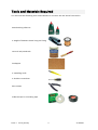
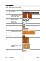
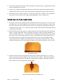
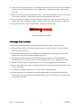
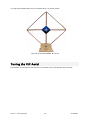
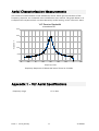
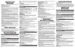
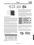
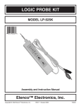
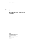
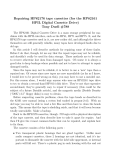
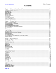
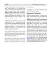
Acknowledgements
Design Team
This aerial design is based on that published by Peter O. Taylor in
Observing the Sun (Cambridge University Press 1991).
The UKRAA VLF Aerial Kit was designed by Norman Pomfret.
Testing Team
The UKRAA VLF Aerial was tested by
Andrew Lutley and Alan Melia.
Production Team
The initial batch of the VLF Aerial Kits was produced by
Norman Pomfret.
Contributors
The following authors have contributed to the VLF Aerial Manual:
John Cook, Andrew Lutley, Dr Laurence Newell and Norman Pomfret.
Issue 1 2010 January
1
© UKRAA
Table of Contents
Introduction.........................................................................................................................3
UKRAA.............................................................................................................................3
The UKRAA VLF Aerial......................................................................................................3
Support............................................................................................................................3
Tools and Materials Required...............................................................................................4
List of Parts.........................................................................................................................5
Assembly Procedure.............................................................................................................6
First stage: the frame sub-assembly.................................................................................6
Second stage: the frame support clamp............................................................................7
Third stage: the frame base..............................................................................................8
Fourth stage: winding the aerial.......................................................................................8
Fifth stage: final assembly................................................................................................9
Tuning the VLF Aerial.........................................................................................................10
Aerial Characterisation Measurements................................................................................11
Appendix 1 – VLF Aerial Specifications...............................................................................11
Appendix 2 – Regulatory Compliance.................................................................................12
RoHS..............................................................................................................................12
WEEE..............................................................................................................................12
Glossary............................................................................................................................13
Contacts ...........................................................................................................................13
Revision History.................................................................................................................14
Outstanding Work..........................................................................................................14
Issue 1 2010 January
2
© UKRAA
Introduction
This Manual describes how to construct the UKRAA VLF Aerial from the kit. Please note that
the Kit provides only the aerial loop, which must be tuned by a capacitor before it can be
used with a receiver. UKRAA can supply a boxed Aerial Tuning Unit (ATU), or you may wish
to provide your own variable capacitor. The external capacitor should have a value between
approximately 10,000pF and 40,000pF, depending on the frequency of operation.
UKRAA
The UK Radio Astronomy Association (UKRAA) is a non-profit-making charitable company
limited by guarantee. It was established by the Radio Astronomy Group of the British
Astronomical Association (BAA) to facilitate the production and sale of radio astronomy
products.
Any suggestions or recommendations for improvement of this Manual would be appreciated.
See the Contacts page for further details.
The UKRAA VLF Aerial
The UKRAA VLF Aerial is designed to receive VLF radio transmissions at suitable frequencies
for the UKRAA VLF Receiver. It is used in conjunction with a tuning unit such as the UKRAA
Aerial Tuning Unit, to form a ‘parallel tuned circuit’ to provide an input signal to the Receiver
in the frequency range 15-35 kHz.
Support
All users of the UKRAA VLF Receiver system are encouraged to make use of the support
available from UKRAA for setting up and operation. Please see the Contacts section for
details.
Issue 1 2010 January
3
© UKRAA
Tools and Materials Required
You will need the following tools and materials to construct the VLF Aerial from the kit:
Woodworking adhesive
A weight of between about 200g and 500g
Varnish and paintbrush
Sandpaper
A modelling knife
A Pozidriv screwdriver
Wire cutters
Adhesive tape or insulating tape
Issue 1 2010 January
4
© UKRAA
List of Parts
The VLF Aerial kit comprises the following:
Part
Qty
Description
1
2
2
2
3
2
4
1
5
1
6mm nut
6
1
6mm T nut
7
1
8
2
9
2
10
1
11
1
12
1
Picture (not to scale)
580mm x 20mm x 12mm
frame cross spars
100mm x 100mm x 9mm
ply frame side plates
6mm flat washers
60mm x 6mm
machine screw
160mm x 20mm x 12mm
clamp base strip
160mm x 100mm x 12mm
clamp side plates
50mm x 20mm x 12mm
clamp frame guide strips
200mm x 200mm x 6mm
base plate
200mm x 200mm x 1.5mm
Cork mat
Countersunk 20mm x 6mm
Posidriv screw
Issue 1 2010 January
5
© UKRAA
500g spool of 24 SWG
13
1
enamelled copper wire supplied with kit UKR006
(frame with wire on reel) only
14
12
Cable ties
15
2
Insulation sleeving
16
1
UKRAA Label
Please check that your kit contains all of the above parts. Any shortages should be notified
to UKRAA (contact details in the Contacts section of the VLF Receiver User Manual) as soon
as possible.
Assembly Procedure
First stage: the frame sub-assembly
1. Apply adhesive to the 12mm rebated central sections of the two frame cross spars (1)
and press firmly together.
Try to keep the central hole clear of adhesive.
2. Take the two frame side plates (2), noting that each has an outside face with chamfered
edges. Lay the first side plate over the centre of the frame cross spars with the corners
over the spars. Use a pencil to lightly mark the location of the four side plate corners on
the cross spars. Apply adhesive to the cross spars up to the pencil marks and place the
first side plate over the cross spars, with the chamfered edges on top.
Again, try to keep the central hole clear of adhesive.
3. Put one washer (3) on the 60mm x 6mm machine screw (4), thread the screw down
through the central hole in the first side plate and cross spars and invert the assembly.
4. Repeat step 2 above for the second side plate.
5. Put the second washer (3) and the 6mm nut (5) on the machine screw and gently tighten.
Issue 1 2010 January
6
© UKRAA
6. If necessary adjust the position of the side plates so that they are in alignment with each
other and with the cross spars.
7. Leave to dry. When assembled and with the nut loosened, the frame should be able to
rotate on the machine screw, which will facilitate subsequent winding of the aerial coil.
8. Remove the screw, washers and nut. Varnish the frame sub-assembly. We recommend
two coats of clear varnish, with a light sanding between coats. Leave to dry.
Second stage: the frame support clamp
9. Press the T nut (6) firmly down into the clamp base strip (7) using a vice. If a vice is not
available, the T nut can be tapped in with a hammer. Any minor distortion of the clamp
base strip side(s) caused by the insertion of the T nut should be made good by filing or
sanding the side(s) flat so as to ensure a good mating surface when subsequently gluing
to the clamp side plate.
10. Take the two clamp side plates (8), noting that each has an outside face with chamfered
edges. Lay the clamp base strip (7) over the inside face of the first clamp side plate – it
does not matter which one - as shown below and lightly mark the position of the clamp
base strip on the clamp side plate with a pencil. Apply adhesive to the marked area of
the clamp side plate and place the clamp base strip on top. Place a suitable weight
(200-500g, such as a stapler or the wire spool) on top of the clamp base strip. Check
that the clamp base strip is flush with the bottom of the clamp side plate. Leave to dry.
Clamp side plate
11. Take the second clamp side plate and place the two frame guide strips (9), as shown
below, using the cross spar with the pre-drilled hole as a spacer. The top of the frame
guide strips should be flush with the top of the clamp side plate. Mark their position
with a pencil, but do not glue them at this stage.
Clamp side plate with frame guide strip
Issue 1 2010 January
7
© UKRAA
12. Varnish the two clamp plate sub-assemblies and the two frame guide strips (9), as
described in step 8 above. NB Do not varnish the surfaces which will be glued in step 13
below or the ‘outside’ surfaces of the frame guide strips. The base plate can also be
varnished at this stage as described in step 14 below. Leave to dry.
13. Apply adhesive to the ‘open’ side of the clamp base strip. Using the two frame guide
strips as spacers (these must not be glued at this stage), press the two clamp plate subassemblies together and place a suitable weight on top of the assembly as described in
step 10 above. Check that the clamp plates are aligned and that the clamp base strip is
flush with the bottom of the clamp side plates. Leave to dry. Remove the two frame
guide strips.
Third stage: the frame base
14. Varnish the top and chamfered edges of the base plate (10), as described in step 8
above. Do not varnish the underside. Leave to dry.
15. Glue the cork mat (11) to the underside of the base plate and place a suitable weight on
top of the base plate as described in step 10 above. Leave to dry. Use a sharp bladed
modelling knife or Stanley knife to trim the edges of the cork mat flush if necessary.
Fourth stage: winding the aerial
16. Use 24 SWG enamelled copper wire for this stage. A 500g spool of 24 SWG enamelled
copper wire is supplied with kit UKR006 (frame with wire on reel). It is not included in kit
UKR005 (frame only). Suitable wire is available from Rapid (part no 05-0230). Maplin
part no YN84 is also suitable but is supplied in 250g reels, which will involve soldering –
see step 17 below.
It is possible to use slightly thicker or thinner wire, but this will affect the inductance of
the tuned aerial, which will affect the capacitance required to tune it to the desired
frequency – for further information see Martyn Kinder’s BAA SID VLF Receiver Project
website http://www.czd.org.uk/astro/radioastro/sid/index.html. Should you wish to use
your own aerial wire, please note that we do not recommend using wire of a smaller
diameter, since this will increase the resistance, and hence lower the sensitivity.
17. If it is necessary to join two lengths of enamelled copper wire, use a modelling knife and
sandpaper to strip back the enamel coating from about 1 cm at the end of each wire
before soldering.
18. Mount the spool of wire on a spindle – a pencil will suffice. The spindle can either be
clamped in a vice or hand held – the latter allows slight tension to be applied, which may
assist with winding.
19. The aerial frame can either be hand held or mounted on a spindle – the 60mm x 6mm
machine screw (4) or a 6mm rod will serve for this purpose.
Issue 1 2010 January
8
© UKRAA
20. Using a strip of adhesive tape or insulating tape, secure the end of the wire to the centre
of the cross spar member with the pre-drilled hole. Tape the wire again at the end of
the spar.
21. Wind 125 turns of wire onto the aerial frame. The precise number of turns is not critical
as each turn only has a slight effect on the final inductance of the aerial.
22. Tape the free end of the wire to the same spar member as used in step 20 above and
secure with strips of adhesive tape or insulating tape at the end and centre of the spar.
23. Apply the cable ties (14) as shown below – three ties to each side.
Cable tie applied to windings
Fifth stage: final assembly
24. Remove the adhesive tape or insulating tape applied in steps 20 and 22 above.
25. Thread the two ends of the wire through the lower of the two holes in the clamp side
plate, from inside to out.
26. Thread the machine screw (4), using the associated washers, through the clamp side
plates and frame spar and gently tighten the nut (5).
27. Thread the countersunk screw (12) through the base plate (10), from the bottom,
through the hole in the base strip so that it engages in the T nut. Tighten the screw.
28. Adjust the aerial frame so that the frame is vertical and tighten the central nut (5).
29. Glue in the frame guide strips on either side of the central spar flush with the top of the
clamp side plates.
30. Thread the Insulation sleeving (15) over the ends of the aerial wire.
31. Please note that if you intend to mount the UKRAA Aerial Tuning Unit directly to the
aerial base, then you should not fit the M6 bolt (4), nut (5) and washers (3), since these
will obstruct the ATU.
Issue 1 2010 January
9
© UKRAA
32. Apply the UKRAA label to your finished aerial, as shown below.
The fully assembled UKRAA VLF aerial
Tuning the VLF Aerial
Instructions for tuning the VLF Aerial are contained in the VLF Receiver User manual.
Issue 1 2010 January
10
© UKRAA
Aerial Characterisation Measurements
The results of measurements on the UKRAA loop aerial, which give an indication of the
frequency response, are contained in the VLF Receiver User manual. The graph below is an
example of the response which can be achieved by careful tuning, in this case to 23.4kHz.
VLF Receiver Bandwidth
at maximum"Q"
2500
Output in mV
2000
1500
1000
500
0
22.6
22.8
23
23.2
23.4
23.6
23.8
24
24.2
Frequency in kHz
Frequency Response of UKRAA VLF Aerial Tuned to 23.4kHz
Appendix 1 – VLF Aerial Specifications
Frequency range
Issue 1 2010 January
15-35 kHz
11
© UKRAA
Appendix 2 – Regulatory Compliance
RoHS
The Directive on the restriction of the use of certain hazardous substances in electrical and
electronic equipment 2002/95/EC, (commonly referred to as the Restriction of Hazardous
Substances Directive or RoHS) was adopted in February 2003 by the European Union. The
RoHS directive took effect on 2006 July 1, and is required to be enforced and become law in
each member state. This directive restricts the use of six hazardous materials in the
manufacture of various types of electronic and electrical equipment. In speech, RoHS is often
spelled out, or pronounced “rosh”.
The above paragraph was taken from the Wikipedia essay on RoHS.
The RoHS Directive restricts the use of the following six hazardous substances in electronic
and electrical equipment products falling within the Directive:
•
Lead
•
Mercury
•
Cadmium
•
Hexavalent chromium
•
Polybrominated biphenyls
•
Polybrominated diphenyl ethers
UKRAA confirms that the suppliers of the components and materials used in the UKRAA VLF
Aerial have stated that such components and materials are RoHS compliant and that
reasonable steps have been taken to confirm these statements.
WEEE
RoHS is closely linked with the Waste Electrical and Electronic Equipment Directive (WEEE)
2002/96/EC that sets collection, recycling and recovery targets for electrical goods and is
part of a legislative initiative to solve the problem of huge amounts of toxic e-waste.
The Waste Electrical and Electronic Equipment (WEEE) Directive is designed to ensure the
efficient collection and recycling of electrical and electronic equipment at end-of-life. If a
customer purchases a new product from UKRAA which falls within the WEEE Directive to
replace an existing one (of similar function to the one that has been sold) and intends to
dispose of the existing one, then the customer can request that we take back the existing
product and deal with the costs and logistics of recycling it. Any customer wishing to take
advantage of this facility should contact us. Provided that the existing product comes within
the scope of the WEEE Directive, we will make arrangements for its return or collection and
will deal with its disposal.
Issue 1 2010 January
12
© UKRAA
Glossary
RoHS
Restriction of Hazardous Substances
SWG
Standard Wire Gauge
UKRAA
The UK Radio Astronomy Association
VLF
Very Low Frequency
WEEE
Waste Electrical and Electronic Equipment
Contacts
The UK Radio Astronomy Association
Springfield
Rookery Hill
Ashtead Park
Ashtead
Surrey
KT21 1HY
Limited by Guarantee Reg. No. 6481611
Registered UK Charity No. 1123866
E-mail: [email protected]
Website: www.ukraa.com
Fax: 0870 132 3728
Telephone: 01372 279066
Starbase Information
Website: www.starbase.org
BAA Radio Astronomy Group
Website: www.britastro.org/radio
Issue 1 2010 January
13
© UKRAA
Revision History
Revision
Date
Author
Status
Draft A
2009-08-08
A J Lutley
Internal draft for peer review, layout by LMN
Issue 1
2010-01-12
L M Newell
Incorporated reviewer's comments
Outstanding Work
None, document is at Issue status
Limited by Guarantee Reg. No. 6481611
Registered UK Charity No. 1123866
Issue 1 2010 January
14
© UKRAA