1
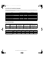
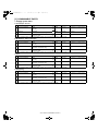
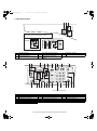
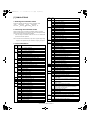
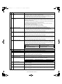
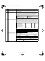
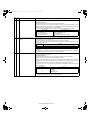
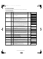
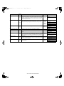
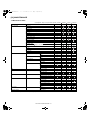
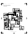
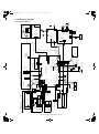
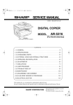
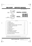
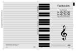
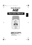
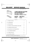
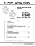
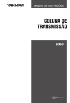
[00]COVER.fm 1 ページ
2003年12月19日 金曜日 午後3時25分
CODE : 00ZAR5320/A1E
DIGITAL COPIER
AR-5316
MODEL
AR-5316
AR-5320
AR-5320
(with option installed)
CONTENTS
[ 1 ] NOTE FOR THIS SERVICE MANUAL . . . . . . . . . . . . . . . Refer to AR-M160
[ 2 ] SPECIFICATIONS . . . . . . . . . . . . . . . . . . . . . . . . . . . . . . . . . .AR-5316/5320
[ 3 ] CONSUMABLE PARTS. . . . . . . . . . . . . . . . . . . . . . . . . . . . . .AR-5316/5320
[ 4 ] EXTERNAL VIEWS AND INTERNAL STRUCTURES . . . . . .AR-5316/5320
[ 5 ] UNPACKING AND INSTALLATION . . . . . . . . . . . . . . . . . . . . .AR-5316/5320
[ 6 ] ADJUSTMENTS . . . . . . . . . . . . . . . . . . . . . . . . . . . . . . . . Refer to AR-M160
[ 7 ] SIMULATIONS . . . . . . . . . . . . . . . . . . . . . . . . . . . . . . . . . . . .AR-5316/5320
[ 8 ] USER PROGRAMS . . . . . . . . . . . . . . . . . . . . . . . . . . . . . . . .AR-5316/5320
[ 9 ] TROUBLE CODE LIST . . . . . . . . . . . . . . . . . . . . . . . . . . . Refer to AR-M160
[10] MAINTENANCE . . . . . . . . . . . . . . . . . . . . . . . . . . . . . . . . . . .AR-5316/5320
[11] DISASSEMBLY AND ASSEMBLY . . . . . . . . . . . . . . . . . . . Refer to AR-M160
[12] FLASH ROM VERSION UP PROCEDURE . . . . . . . . . . . Refer to AR-M160
[13] ELECTRICAL SECTION . . . . . . . . . . . . . . . . . . . . . . . . . . . . .AR-5316/5320
Parts marked with “ “ are important for maintaining the safety of the set.
Be sure to replace these parts with specified ones for maintaining the safety and performance of the set.
SHARP CORPORATION
This document has been published to be used for
after sales service only.
The contents are subject to change without notice.
[01_02]NOTE_SPEC.fm 1 ページ
2003年12月19日 金曜日 午後4時9分
[1] NOTE FOR THIS SERVICE MANUAL
This Service Manual describes only the items related to the AR-5316 and AR-5320. For the other items common with the AR-M160/M205, please refer
to the AR-M160/205 Service Manual (Document code:00ZARM205/A1E). The table below shows which document(s) should be referred to for each
section. (Refer to the document marked with O.)
Section
[ 1 ] GENERAL
[ 2 ] SPECIFICATIONS
[ 3 ] CONSUMABLE PARTS
[ 4 ] EXTERNAL VIEWS AND INTERNAL STRUCTURES
[ 5 ] UNPACKING AND INSTALLATION
[ 6 ] ADJUSTMENTS
[ 7 ] SIMULATIONS
[ 8 ] USER PROGRAMS
[ 9 ] TROUBLE CODE LIST
[10] MAINTENANCE
[11] DISASSEMBLY AND ASSEMBLY
[12] FLASH ROM VERSION UP PROCEDURE
[13] ELECTRICAL SECTION
AR-M160/M205
O
O
AR-5316/AR-5320
O
O
O
O
O
O
Changed item
O
O
O
O
Some specifications
O
O
Shifter sensors status display, etc. deleted.
USB2.0 mode switch, etc. deleted.
Appearance / Internal / Operation panel
Changing the copy paper size in the tray
O
O
O
O
O
Block diagram / Actual wiring diagram 1/7
[2] SPECIFICATIONS
The table below shows the specifications of this model and the contents of changes from the AR-M160/M205 and AR-5316/5320.
Item
Paper feed system
AR-M160
1cassette +
Multi manual paper feed
Weight
Approx.31.3Kg
Interface
USB1.1/USB2.0
IEEE1284
AR-5316
One automatic feeding paper
tray(250sheets) +
bypass tray(100sheets)
Approx.31.3Kg
(Not including TD cartridge)
IEEE1284parallel connector/
USB1.1
AR-M205
2cassette +
Multi manual paper feed
Approx.35.1Kg
USB1.1/USB2.0
IEEE1284
AR-5320
Two automatic feeding paper
trays(250sheets each) +
bypass tray(100sheets)
Approx.36.3Kg
(Not including TD cartridge)
IEEE1284parallel connector/
USB1.1
Option
AR-M160
AR-M205
AR-5316
AR-5320
250 sheets paper feed unit
Machine
AR-D24 / D25
Model
O
O
-
-
SPF
AR-SP6
O
-
O
O
RSPF
AR-RP6
-
O
-
-
Original cover
AR-VR5
Standard
O
Standard
Standard
O : The option can be installed.
- : The option cannot be installed.
AR-5316/5320 NOTE FOR THIS SERVICE MANUAL 1-1
Remark
[03]CONSUMABLEPARTS.fm
1 ページ 2004年1月19日 月曜日 午後1時49分
[3] CONSUMABLE PARTS
1. Supply system table
A. East Europe / Russia
NO
Name
Content
Life
1
Toner cartridge(Black)
<With IC>
Toner
(Toner: Net Weight 537g)
Vinyl bag
x10
2
Developer
Developer
(Developer : Net Weight 400g)
3
Drum kit
Drum
Drum fixing plate
Product name
Remark
160K
AR-016LT
Life setting by A4 6% document
LT=T*10
x10
500K
AR-202LD
LD=DV*10
x1
x1
50K
AR-202DM
x10
Note 1: The individual carton is printed with English, German, French, and Spanish as well as the green mark.
B. Middle East / Africa / Philippine
NO
Name
Content
Life
1
Toner cartridge(Black)
<With IC>
Toner
(Toner: Net Weight 537g)
Vinyl bag
x10
2
Developer
Developer
(Developer : Net Weight 400g)
3
Drum kit
Drum
Drum fixing plate
Product name
Remark
190K
AR-016ET
Life setting by A4 6% document
ET=FT*10
x10
500K
AR-202CD
CD=SD*10
x1
x1
50K
AR-202DR
x10
Note 1: The individual carton is printed with English, German, French, and Spanish as well as the green mark.
C. Asia
NO
Name
Content
Life
1
Toner cartridge(Black)
<With IC>
Toner
(Toner: Net Weight 537g)
Vinyl bag
x10
2
Developer
Developer
(Developer : Net Weight 400g)
3
Drum kit
Drum
Drum fixing plate
Product name
Remark
190K
AR-016CT
Life setting by A4 6% document
CT=ST*10
x10
500K
AR-202CD
CD=SD*10
x1
x1
50K
AR-202DR
x10
Note 1: The individual carton is printed with English, German, French, and Spanish as well as the green mark.
D. Hong Kong
NO
Name
Content
Life
1
Toner cartridge(Black)
<With IC>
Toner
(Toner: Net Weight 537g)
Vinyl bag
x10
2
Developer
Developer
(Developer : Net Weight 400g)
3
Drum kit
Drum
Drum fixing plate
Product name
Remark
190K
AR-016CT-C
Life setting by A4 6% document
CT-C=ST-C*10
x10
500K
AR-202CD-C
CD-C=SD-C*10
x1
x1
50K
AR-202DR-C
x10
Note 1: The individual carton is printed with English and Chinese as well as the green mark.
AR-5316/5320 CONSUMABLE PARTS 3-1
[04]EXTERNALVIEWS.fm 1 ページ
2003年12月19日 金曜日 午後3時26分
[4] EXTERNAL VIEWS AND INTERNAL STRUCTURES
1. Appearance
1
6
1
15
2
16
3
5
3
9
4
7
10
14
11
8
1
4
7
10
13
16
Document feeder cover (when the SPF
is installed) /document cover
Power switch
Front cover
Side cover handle
Bypass tray extension
Parallel connector
12
13
2
Document glass
3
Handles
5
8
11
14
Operation panel
Paper trays
Bypass tray guides
Charger cleaner
6
9
12
15
Paper output tray
Side cover
Bypass tray
USB 1.1 connector
2. Internal
17 18
19
21
20
22
24
26
25
27
23
17
20
23
26
Document feeder tray
(when the SPF is installed)
Right side cover
(when the SPF is installed)
Toner cartridge
Photoconductive drum
18
21
24
27
Original guides
(when the SPF is installed)
Exit area
(when the SPF is installed)
Roller rotating knob
Fusing unit paper guide
19
22
Feeding roller cover
(when the SPF is installed)
Toner cartridge lock release lever
25
Fusing unit release levers
AR-5316/5320 EXTERNAL VIEWS AND INTERNAL STRUCTURES 4-1
[04]EXTERNALVIEWS.fm 2 ページ
2003年12月19日 金曜日 午後3時26分
3. Operation Section
1
2
3
6
XY-ZOOM key/indicator
ORIGINAL SIZE ENTER key /
ORIGINAL SIZE indicators
3
The indications of the operation panel may differ
depending on the country and the region.
The example of a display of inch series
AR-5316/
AR-5316X
200%
141
129
121
100%
95
77
64
50%
11X17
8½X14
8½X11
8½X5½
8½X11
8½X13
EXTRA
5
4
1
4
7
6
ON LINE key/indicator
SPF indicator
(when the SPF is installed)
PAPER SIZE indicators
2
5
8
7
8
5
4
DUAL PAGE COPY key/indicator
Paper feed location / misfeed location
indicators
PRESET RATIO selector keys /
indicators
11
9
12
10
ACC.#-C
13
AUTO
A3
A4
A4
A5
B4
EXTRA
1 3 5
17
18
ZOOM
25 400%
INTERRUPT
AUTO %
ENTER
6
16
200%
141
122
115
100%
86
81
70
50%
AUTO
19
15
14
7 20 4 21
22
5
8
24
23
25
26 27
Not used for this machine.
9
12
15
18
21
24
27
AUTO/TEXT/PHOTO key / indicators
Alarm indicators
Copy ratio display key
INTERRUPT key / indicator
TRAY SELECT key
# key
CLEAR key
10
13
16
19
22
25
AUDIT CLEAR key
POWER SAVE indicator
ZOOM indicator
Light and Dark keys / indicators
AUTO IMAGE key / indicator
START key / indicator
11
14
17
20
23
26
AUTO PAPER SELECT indicator
Display
Zoom keys
PAPER SIZE ENTER key
Numeric keys
CLEAR ALL key
AR-5316/5320 EXTERNAL VIEWS AND INTERNAL STRUCTURES 4-2
[05]UNPACKING.fm 1 ページ 2003年12月19日 金曜日 午後3時26分
[5]UNPACKING AND INSTALLATION
5. Changing a tray's paper size setting
4) Squeeze the lock lever of the front guide and slide the front guide to
match the width of the paper, and move the left guide to the
appropriate slot as marked on the tray.
Follow these steps to change a tray's paper size setting.
Left guide
Note:
•The paper size setting cannot be changed when the machine has
stopped temporarily due to running out of paper or a misfeed, or during
interrupt copying.
•During printing (even in copy mode), the paper size setting cannot be
changed.
•A5 size paper can only be selected in upper paper tray.
•Do not load paper that is a different size than the paper size setting.
Copying will not be possible.
1) Hold down the [PAPER SIZE ENTER] key for more than 5 seconds to
set the selected paper size.
The currently selected paper feed location indicator will blink and the
corresponding paper size (which is currently set) indicator will light
steadily.
All other indicators will go out.
Front guide
•The front guide is a slide-type guide. Grasp the locking knob on the
guide and slide the guide to the indicator line of the paper to be loaded.
•The left guide is an insert-type guide. Remove it and then insert it at the
indicator line of the paper to be loaded.
•When using 11" x 17" sized paper store the left guide in the slot at the
left front of the paper tray.
A3
A4
A4
A5
B4
XTRA
2) If the machine has two paper trays, use the [TRAY SELECT] key to
select the paper tray for which you wish to change the paper size
setting.
Each time the [TRAY SELECT] key is pressed, a paper tray will be
indicated with a blinking paper feed location indicator.
3) Use the [ORIGINAL SIZE ENTER] key to select the paper size.
The indicator of the selected paper size lights up.
5) Press the [START] key and then the [PAPER SIZE ENTER] key.
To change the paper size setting of another tray, repeat steps 2) to 5)
after pressing the [START] key.
Note: Affix the paper size label for the paper size selected in step 3) to
the label position on the right end of the tray.
Important points when using the printer mode
A3
ENTER A4
A4
A5
B4
TRA
•Make sure that the tray's paper size setting is the same as the tray's
paper size setting in the printer driver. For example, if the tray's paper
size setting is A4R, set "Setting Paper Size" to "A4-R". For more
information, see "CONFIGURING THE PRINTER DRIVER" in the
"Software Setup Guide".
AR-5316/5320 UNPACKING AND INSTALLATION 5-1
[07]SIMULATIONS.fm 1 ページ
2003年12月19日 金曜日 午後3時26分
[7] SIMULATIONS
Main
code
Sub
code
Contents
15
Trouble memory display
17
Copy counter display
18
Printer counter display
21
Scanner counter display
22
SPF jam counter display
01
Jam total counter clear
2. Canceling the simulation mode
02
Trouble memory clear
04
SPF counter clear
When the clear all key is pressed, the simulation mode is cancelled.
When the interruption key is pressed, the process is interrupted and the
screen returns to the sub code entering display.
* After canceling the simulation mode, be sure to turn OFF/ON the
power and check the operation.
06
Paper feed counter clear
07
Drum counter clear
08
Copy counter clear
09
Printer counter clear
13
Scanner counter clear
14
SPF jam total counter clear
01
Main motor operation check
10
Polygon motor operation check
02
Size setting
03
Auditor setting
05
Count mode setting
06
Destination setting
22
1. Entering the simulation mode
Perform the following procedure to enter the simulation mode.
"#" key
Interrupt key
"C" key
Interrupt key
Main code
Start key
Sub code
Start key
24
Note: If the machine is terminated by a jam error or paper empty during
copying in the adjustment by the simulation, recopying is required.
25
26
3. List of simulations
Main
code
Sub
code
01
01
Mirror scanning operation
07
Machine condition check (CPM)
02
Mirror home position sensor (MHPS) status display
18
Toner save mode setting
06
Mirror scanning operation aging
30
CE mark conformity control ON/OFF
01
Single paper feeder (SPF) aging
31
Auditor mode exclusive setup
02
SPF sensor status display
36
Cancel of stop at maintenance life over
03
SPF motor operation check
37
Cancel of stop at developer life over
08
SPG paper feed solenoid operation check
38
Cancel of stop at drum life over
11
SPF PS release solenoid operation check
39
Memory capacity check
01
Operation panel display check
42
Transfer ON/OFF timing control setting
02
Fusing lamp and cooling fan operation check
43
Side void amount setting
03
Copy lamp lighting check
51
Copy temporary stop function setting
01
Paper feed solenoid operation check
30
01
Paper sensor status display
02
Resist roller solenoid operation check
42
01
Developing counter clear
10
Cassette semi-circular roller cleaning
43
01
Fusing temperature setting
01
Warm-up display and aging with jam
12
Standby mode fusing fan rotation setting
06
Intermittent aging
13
Fusing paper interval control allow/inhibit setting
08
Shifting with warm-up display
34
Transfer current setting
01
Developing bias output
40
Setting of rotation time before toner supply
02
Main charger output (Grid = HIGH)
01
Copy density adjustment (300dpi)
03
Main charger output (Grid = LOW)
02
Copy density adjustment (600dpi)
06
Transfer charger output
09
Copy exposure level adjustment, individual setting
(Text) 300dpi
10
Copy exposure level adjustment, individual setting
(Text) 600dpi
11
Copy exposure level adjustment, individual setting
(Photo) 600dpi
02
05
06
07
08
Contents
44
46
10
-
Toner motor operation
14
-
Trouble cancel (except for U2)
16
-
U2 trouble cancel
20
01
Maintenance counter clear
21
01
Maintenance cycle setting
02
Mini maintenance cycle setting
18
Image contrast adjustment (300dpi)
01
Maintenance counter display
19
02
Maintenance preset display
03
Jam memory display
Exposure mode setting
(Gamma table setting/AE operation mode setting/
Photo image process setting)
04
Jam total counter display
20
SPF exposure correction
05
Total counter display
29
Image contrast adjustment (600dpi)
06
Developing counter display
30
AE limit setting
07
Mini maintenance preset display
31
Image sharpness adjustment
08
SPF counter display
01
Main scanning magnification ratio adjustment
09
Paper feed counter display
05
SPF/RSPF mode sub scanning magnification ratio
adjustment in copying
12
Drum counter display
13
CRUM type display
14
P-ROM version display
22
48
49
01
Flash ROM program writing mode
12
Standby mode fusing fan RPM setting
AR-5316/5320 SIMULATIONS 7-1
[07]SIMULATIONS.fm 2 ページ
Main
code
2003年12月19日 金曜日 午後3時26分
Sub
code
Contents
01
Image lead edge adjustment
06
Copy lead edge position adjustment (SPF/RSPF)
10
Paper off-center adjustment
12
Document off-center adjustment
51
02
Resist amount adjustment
53
08
SPF scanning position automatic adjustment
10
SPF scan position change-over setting
61
03
HSYNC output check
63
01
Shading check
07
SPF automatic correction
01
Self print
50
64
4. Contents of simulations
Main Sub
code code
Contents
Details of operation
01
06
Mirror scanning operation aging
When the [START] key is pressed, the mirror base performs A3 full scanning at the set magnification
ratio speed. During scanning, the set magnification ratio is displayed. After 3 seconds, the mirror
base performs full scanning again. During scanning, the set magnification ratio is displayed.
* When the [START] key is pressed again, the ready lamp turns and remains off.
The DV replacement/OPC drum cartridge replacement lamp displays the status of the mirror
home position sensor. (The lamp lights up when the mirror is in the home position.)
During aging, the copy lamp lights up. When the [Interrupt] key is pressed, the operation is
interrupted if operating, and the machine goes into the sub code input standby mode.
02
01
Single paper feeder (SPF) aging
When the [START] key is pressed, the set magnification ratio is acquired and document transport
operation of single surface is performed in the case of SPF or document transport operation of
duplex surfaces is performed. During operation, the LED on the display section corresponding to the
selected magnification ratio lights up, and the magnification ratio is displayed on the 7-seg display.
When the [Interrupt] key is pressed at that time, the machine goes to the sub code input standby
mode. When the [CA] key is pressed, the simulation is terminated.
02
SPF sensor status display
(In order to receive the sensor change notification, the load must be decreased.)
The sensor status (ON/OFF) in the SPF can be checked with the following lamps.
When a sensor detects paper, it turns on. The open/close detection sensor turns on when the
machine is opened.
Display lamp
Sensor
Toner supply lamp
Copier jam lamp
The DV replacement/OPC drum cartridge
replacement lamp
Paper empty lamp
SPF jam lamp
Manual paper feed lamp
Tray jam lamp
AE lamp
TEXT lamp
PHOTO lamp
SPF document set sensor
SPF document transport sensor
SPF unit (OC cover) open/close sensor
SPF paper exit sensor
SPF paper feed cover open/close sensor
SPF paper length sensor 1
SPF paper length sensor 2
SPF paper feed width sensor (small)
SPF paper feed width sensor (middle)
SPF paper feed width sensor (large)
When the [Interrupt] key is pressed, the machine goes to the sub code input standby mode.
When the [CA] key is pressed, the simulation is terminated.
06
01
Paper feed solenoid operation
check
When this simulation is executed, the sub code is displayed on the 7-seg LED and the lamp
corresponding to the solenoid lights up.
Select a solenoid with the tray select key (the lamp corresponding to the solenoid lights up) and
press the [START] key, and the machine repeats operation of ON for 500ms and OFF for 500ms.
This operation is repeated 20 times.
After that, the machine goes into the sub code entry standby mode.
When [INTERRUPT] key is pressed during the process, the machine goes into the sub code input
standby mode. When [CA] key is pressed, the simulation is terminated.
Display lamp
Main cassette lamp
2nd cassette lamp
Manual paper feed lamp
2nd cassette jam lamp
Machine jam lamp & 2nd cassette jam lamp
*
Solenoid
Main cassette paper feed solenoid
* 2nd cassette paper feed solenoid
Manual paper feed solenoid
* 2nd cassette paper transport solenoid
* 3rd cassette transport solenoid
Supported for the installed models only. Skipped for the models without installation.
AR-5316/5320 SIMULATIONS 7-2
[07]SIMULATIONS.fm 3 ページ
Main Sub
code code
06
08
2003年12月19日 金曜日 午後3時26分
Contents
Details of operation
02
Resist roller solenoid operation
check
When the [START] key is pressed in the sub code input state, the resist solenoid (RRS) turns ON for
500ms and OFF for 500ms. This operation is repeated 20 times.
After completion of the process, the machine goes into the sub code input standby mode.
When [INTERRUPT] key is pressed during the process, the machine goes into the sub code input
standby mode. When [CA] key is pressed, the simulation is terminated.
10
Cassette semi-circular roller
cleaning
First of all, remove the developer unit.
Enter the simulation code, specify the cassette to be cleaned with the tray select key, and press
START button. The main motor rotates to move the cassette semi-circular roller by half circle and
make the roller face downward.
After completion of cleaning, when INTERRUPT key is pressed, the machine goes into the sub code
entry standby mode and the roller returns to the original positions.
To clean another roller continuously, press INTERRUPT key to return the roller to the original
position, and execute the simulation again.
During the operation, the sub code is displayed on the display.
* When CA key is pressed, the simulation mode is terminated.
However, the roller returns to the original position by the initial operation.
01
Developing bias output
When the [START] key is pressed, the developing bias signal is turned ON for 30 sec.
However, to calculate the actual output value is calculated, execute SIM25-01.
After completion of the process, the machine goes into the sub code input standby mode.
When [INTERRUPT] key is pressed during the process, the machine goes into the sub code input
standby mode. When [CA] key is pressed, the simulation is terminated.
02
Main charger output (Grid = HIGH) When the [START] key is pressed, the main charger output is supplied for 30 sec in the grid voltage
HIGH mode. After completion of the process, the machine goes into the sub code input standby
mode.
When [INTERRUPT] key is pressed during the process, the machine goes into the sub code input
standby mode. When [CA] key is pressed, the simulation is terminated.
03
Main charger output (Grid = LOW) When the [START] key is pressed, the main charger output is supplied for 30 sec in the grid voltage
LOW mode. After completion of the process, the machine goes into the sub code input standby
mode.
When [INTERRUPT] key is pressed during the process, the machine goes into the sub code input
standby mode. When [CA] key is pressed, the simulation is terminated.
06
Transfer charger output
Select an output mode with the [Mode select] key and press the [START] key. The transfer charger
output is delivered for 30 sec in the selected mode.
After 30 sec of transfer charger output, the machine goes into the sub code entry standby mode.
When [INTERRUPT] key is pressed during the process, the machine goes into the sub code input
standby mode. When [CA] key is pressed, the simulation is terminated.
Display lamp
Output mode
AE mode lamp
AE mode lamp & PHOTO mode lamp
AE & TEXT & PHOTO mode lamp
22
Normal size width: Front surface
Small size width: Front surface
Manual paper feed mode
•Small size is Letter R (A4R) or smaller.
The maintenance counter value is displayed. (Alternate display by 3 digits)
01
Maintenance counter display
04
Jam total counter display
The jam total counter value is displayed. (Alternate display by 3 digits)
05
Total counter display
The total counter value is displayed. (Alternate display by 3 digits)
06
Developing counter display
The developing counter data is acquired and displayed on the 7-seg display. (Alternate display by 3
digits)
When the [Interrupt] key is pressed, the machine goes into the sub code input standby mode.
When the [CA] key is pressed, the simulation is terminated.
08
SPF counter display
The SPF counter value is displayed. (Alternate display by 3 digits)
14
P-ROM version display
The P-ROM version is displayed on the copy quantity display. The main code and the sub code are
alternatively displayed by 2 digits. The display interval is same as that of the counter display.
By pressing the fixed magnification ratio key, each version display is switched.
Display lamp (AB series)
Display lamp (Inch series)
141%
141%
Displayed version
Machine program
17
Copy counter display
The copy counter value is displayed. (Alternate display by 3 digits) When the [Interrupt] key is
pressed, the machine goes into the sub code input standby mode. When the [CA] key is pressed, the
simulation is terminated.
18
Printer counter display
The printer counter value is displayed. (Alternate display by 3 digits)When the [Interrupt] key is
pressed, the machine goes into the sub code input standby mode. When the [CA] key is pressed, the
simulation is terminated.
21
Scanner counter display
The scanner counter value is displayed. (Alternate display by 3 digits)When the [Interrupt] key is
pressed, the machine goes into the sub code input standby mode. When the [CA] key is pressed, the
simulation is terminated.
AR-5316/5320 SIMULATIONS 7-3
[07]SIMULATIONS.fm 4 ページ
Main Sub
code code
2003年12月19日 金曜日 午後3時26分
Contents
Details of operation
22
22
SPF jam counter display
The SPF jam counter value is displayed. (Alternate display by 3 digits)When the [Interrupt] key is
pressed, the machine goes into the sub code input standby mode. When the [CA] key is pressed, the
simulation is terminated.
44
34
Transfer current setting
Used to set the transfer current for the front surface and that for the back surface. When this
simulation is executed, the current set value is displayed on the 7-seg display. Select the set value
with the zoom (Up/Down) keys and press the [START] key, and the set content is written into the
EEPROM and the machine goes into the sub code input standby mode. Press the [Mode select] key
to select each setting mode. At that time, the setup content is written into the EEPROM.
The set range is 90uA ~ 360uA in the increment of 10uA.
Display lamp
Setting mode
AE mode lamp
AE mode lamp & PHOTO mode lamp
AE & TEXT & PHOTO mode lamps
*
*
49
01
Small size paper must be Letter R (A4R) or smaller.
For the special size of tray, use the normal size width.
Flash ROM program writing mode (Operating procedure)
When this simulation is executed, "d" is displayed on the copy quantity display and the machine
enters the Flash ROM program writing mode. Use the writing tool on the PC to write the program.
During writing, the display is made as follows. After completion of downloading, turn OFF/ON the
power to reset.
Status
Copy quantity display
"d"
"d"
"d"
"d"
"d"
"OFF"
"*E"
Download data reception
Data delete start
Data writing (Boot section)
Data writing (Program section)
Sum check
Completion of downloading
Error status
*
Standby mode fusing fan RPM
setting
Pre-heat lamp
ON
ON
Flash
Flash
ON
OFF
OFF
Ready lamp
OFF
ON
OFF
Flash
ON
OFF
OFF
"*" in the error display indicates the error position.
00
02
03
04
05
06
12
Normal size width: Front
Small size width: Front
Manual paper feed
Data receive error
FLASH ROM delete error
FLASH ROM write error (Boot section)
FLASH ROM write error (Program section)
Sum check error (Loader section)
Sum check error (Boot section)
07
08
09
0b
0F
Sum check error (Program section)
Sum check error (EEPROM section)
E2PROM verify error
E2PROM verify error
Download data length error
When this simulation is executed, the currently set code number is displayed.
When [MODE SELECT] key is pressed, the normal setting and the high fusing temperature setting
are switched alternatively.
Enter the code number and press START key, and the number is written into the EEPROM and the
machine goes into the sub code entry standby mode.
Display lamp
Setting mode
Default
AE mode lamp
Normal temperature control (190°C or less)
Low speed rotation
TEXT mode
Fusing temperature of 190°C or above
High speed rotation
Code number
0
1
Setting
Low speed rotation
High speed rotation
AR-5316/5320 SIMULATIONS 7-4
[07]SIMULATIONS.fm 5 ページ
2003年12月19日 金曜日 午後3時26分
Main Sub
code code
51
02
Contents
Resist amount adjustment
Details of operation
Used to adjust the contact pressure of the machine resist roller and the RSPF resist roller onto the
paper.
(Operating procedure)
When this simulation is executed, the current set value is displayed.
When the exposure mode key is pressed, the following set items are changed sequentially. Enter an
adjustment value with the 10-key and press the [START] key, and the entered value will be saved and
a copy will be made. (Adjustment range: 1 ~ 99, Default: 50)
When the [CA] key is pressed, the entered value is saved and the simulation is terminated.
Lighting lamp
Adjustment mode
AE, Main cassette lamp
AE, 2nd cassette lamp
AE, Manual paper feed lamp
AE, TEXT, PHOTO lamps
Main cassette paper feed
2nd cassette paper feed
Manual paper feed
SPF document feed (Front surface)
Supported for the installed models only. Skipped for the models without installation.
53
10
SPF scan position change-over
setting
Used to change over the scan position depending on that the SPF unit and the SPF document glass
holder section are of anti-dirt glass or not.
When this simulation is executed, the currently set code number is displayed.
Enter the code number corresponding to the SPF unit to be used and press [START] key, and the
setting will be changed over.
Code No.
Mode
0
Set to the scan position of the current mass production SPF unit. (Default)
1
Set to the scan position of the ant-dirt SPF unit.
Though this setting is changed, the other set values are not affected. (The other set values remain
unchanged.)
When replacing and installing the SPF unit, it is recommendable to use this simulation to set the
scan position and execute the scan position automatic adjustment.
64
01
Self print
The optical system status is ignored and a self print is made. Also when a print command is sent
from the host, printing is performed.
(Operating procedure)
When this simulation is executed, warm-up is performed and the ready lamp is lighted.
(However, the scanner is invalid and no initial operation is made.)
Enter the code number with the 10-key, and select a cassette with the cassette select key and press
the [START] key. The selected cassette start paper feed and printing is performed in the selected
pattern.
* Only the tray lamp and the online lamp are lighted, and no other lamps are lighted.
Printing is made in 1 by 2 mode, where one line is printed and the following two liens are not printed,
or in the grid pattern.
Code number
0
1
2
3
*
*
Pattern
1 by 2
Grid pattern
White paper
Black background
Input disable for 4 ~ 99
Print data are made on A3 size. (A3 paper is preferable.)
AR-5316/5320 SIMULATIONS 7-5
[08]USERPROGRAMS.fm 1 ページ
2003年12月19日 金曜日 午後3時27分
[8] USER PROGRAMS
The user programs allow the parameters of certain functions to be set, changed, or canceled as desired.
1. List of user programs
This copier has the following user programs.
Program name
Program
No
Auto clear time
1
Description
"Auto clear time" automatically returns the copy settings to the initial
settings when a certain period of time elapses after a copy is made.
This program is used to select the period of time. "Auto clear time"
can also be disabled.
Default
Parameters
1 (OFF)
2 (10sec)
60sec
3 (20sec)
4 (60sec)
5 (90sec)
6 (120sec)
Preheat mode
2
Auto power shut-off timer
3
Stream feeding mode *1
4
Auto power shut-off
setting
5
Auto paper select mode *2
Account number entry
Account number change
Resetting account
Resolution in Auto/Text
mode
When copying using the SPF, during the period of time that the SPF
indicator blinks after an original has been scanned (about 5
seconds), a subsequent original can be placed and automatically
fed into the machine.
Use this setting to enable or disable auto power shut-off.
2 (5min)
1min
6 (240min)
2 (30min)
3 (60min)
5min
4 (120min)
5 (240min)
0 (OFF)
OFF
ON
9
ON
10
Use to enable or disable "Auditing mode".
"Auditing mode" is initially disabled.
OFF
11
Use to set up account numbers.
Up to 20 accounts can be established.
1 (ON)
0 (OFF)
1 (ON)
0 (OFF)
ON
1 (ON)
0 (OFF)
1 (ON)
0 (OFF)
1 (ON)
-
12
Use to change an account number.
13
Use to delete an account number.
A single account number can be deleted, or all account numbers at
once.
Delete
single
account
14
This displays the number of copies made by each account.
The maximum count is 49,999. If this number is exceeded, the count
will start over from 0.
-
15
Use to reset the copy count of an account to 0.
The copy count of a single account or of all accounts can be reset.
23
This setting is used to change the copy resolution in AUTO and
TEXT mode from 600 x 300 dpi to 600 x 600 dpi
(high-quality mode).
Scanning is slower when high-quality mode is used.
AR-5316/5320 USER PROGRAMS 8-1
4 (60min)
1 (5min)
If the paper runs out during printing and there is paper of the same
size and orientation in another tray, this function automatically
switches to that tray (excluding the bypass tray). The function can be
disabled.
*1 On models with a SPF.
*2 On model with the two trays.
3 (30min)
5 (120min)
8
Account number deletion
Number of copies per
account
This function automatically switches the machine to a state that
consumes even less power than preheat mode if the set duration of
time elapses without the machine being used when the power is on.
All lights except the POWER SAVE indicator and ON LINE indicator
go off. To resume normal operation, press the [START] key. Normal
operation also resumes automatically when a print job is received or
scanning is begun from a computer. While in auto power shut-off
mode, no keys (except the [START] key) can be used.
1 (1min)
This function automatically selects paper that is the same size as
the original placed in the SPF, or the same size as that selected with
the [ORIGINAL SIZE ENTER] key. The function can be disabled.
Auto tray switching *2
Auditing mode
This function automatically switches the machine to a low power
consumption state if the set duration of time elapses without the
machine being used when the power is on.
The POWER SAVE indicator lights up, however, the keys on the
operation panel can be used. Normal operation automatically
resumes when a key on the operation panel is pressed, a print job is
received or an original is placed.
-
-
0 (Delete single account)
1 (Delete all accounts)
-
Reset single 0 (Reset single account)
account
1 (Reset all accounts)
1 (300dpi)
300dpi
2 (600dpi)
[08]USERPROGRAMS.fm 2 ページ
2003年12月19日 金曜日 午後3時27分
Program name
Program
No
Description
25
Use this setting to select whether or not holding down a key causes
repeated input of the key. For keys that normally cause a set value to
increase when held down (for example, holding down the [ZOOM]
key), this program can be used to have the set value not change
when the key is held down.
Key auto repeat
Key press time
Use this setting to select how long a key must be pressed for the
input to be accepted. By selecting a longer time, you can prevent
settings from being changed by the accidental pressing of a key.
26
Default
Parameters
0 (OFF)
1 (ON)
ON
Minimum
(current
response
speed)
1 (Minimum
(current response speed))
2 (0.5sec)
3 (1.0sec)
4 (1.5sec)
5 (2.0sec)
Audible signals volume
This sets the volume of beep signals.
27
1 (short beep)
short beep 2 (long beep)
3 (OFF)
Base setting beep signal
Number of copies limit
28
Use this to sound a beep when a base setting is selected.
OFF
29
Use this setting to select 99 or 999 for the maximum number of
copies.
30
When this function is enabled, printing in printer mode will
automatically continue using a different size of paper if the specified
size of paper runs out in all trays. This feature does not function in
copy mode.
OFF
31
Use this program to select a default tray. This tray is automatically
selected each time the power is turned on or each time the machine
reverts to the initial settings.
Upper
paper tray
Use this program to set "AUTO", "TEXT", or "PHOTO" as the default
exposure mode.
AUTO
Use close paper size
Default tray setting
Default exposure mode
32
999 copies
0 (OFF)
1 (ON)
1 (99 copies)
2 (999 copies)
0 (OFF)
1 (ON)
1 (Upper paper tray)
2 (Lower paper tray)
5 (Bypass tray)
1 (AUTO)
2 (TEXT)
3 (PHOTO)
AR-5316/5320 USER PROGRAMS 8-2
[10]MAINTENANCE.fm 1 ページ
2004年1月19日 月曜日 午後1時52分
[10] MAINTENANCE
1. Maintenance table
X:Check(Clean, adjust, or replace when required.) O:Clean
Unit name
Drum peripheral
Part name
-
Side seal F/R
X
MC unit
X
50K
100K
150K
X
X
X
-
(
)
(
)
(
)
(MC grid)
-
(
)
(
)
(
)
(MC case)
-
(
)
(
)
(
Transfer wire
O
O
O
O
Transfer paper guide
O
O
O
O
MC guide sheet (Cleaning blade attached)
-
Drum fixing plate B
X
Process frame unit
X
X
X
Discharge holder
O
O
O
X
)
O
X
Only for Viet Nam
Developer
-
DV seal
-
X
DV under seal
-
-
-
DV side seal
-
X
X
-
-
-
Reflector
O
O
O
O
Mirror
O
O
O
O
Mirror
O
O
O
O
Pulley
X
X
X
X
CCD peripheral
Lens
O
O
O
O
Glass
Table glass
O
O
O
O
White Plate
O
O
O
O
Drive wire
X
X
X
Lamp unit
No.2/3 mirror unit
Other
Rail
LSU
Paper feed section
:Lubricate
(MC charging electrode)
Side Mylar
Optical section
:Adjust
-
Cleaning blade
Separation pawl
Star ring x 2 pcs
Developing section
When calling
OPC drum
:Replace
Multi paper feed section
O
O
O
O
O
O
Dust-proof glass
O
O
O
O
Take-up roller(manual / SPF)
O
O
O
O
Paper feed roller
O
O
O
O
O
O
PS roller
O
O
O
Transport (paper exit) rollers
O
O
O
O
O
O
Upper heat roller
O
O
O
Pressure roller
O
O
O
Pressure roller bearing
X
X
X
O
O
O
O
O
O
O
O
Upper separation pawl
X
X
X
O
Lower separation pawl
X
X
X
O
Gears
Paper exit section
X
X
O
Cleaning pad
Drive section
X
Document size sensor
Spring clutch
Fusing section
X
Document cover
Spring clutch
Paper transport section
X
X
X
X
X
X
X
X
Belts
X
X
X
O
Ozone filter*1
X
X
X
X
*1:Recommendable replacement time:50K(Letter,5%print)
AR-5316/5320 MAINTENANCE 10-1
[10]MAINTENANCE.fm 2 ページ
2003年12月19日 金曜日 午後3時27分
2. Maintenance display system
Toner
Life,
Remaining
quantity
check *1
Developer
C. DV seal attachment procedure
16K
a. Press and hold the density adjustment
LIGHT key for more than 5 sec, and the
machine will enter the user program
mode.
b. Press and hold the "%" key for more
than 5 sec, and the remaining quantity
will be displayed on the copy quantity
display in one of the following levels:
(Remaining quantity display levels:
100%, 75%, 50%, 25%, 10%, LO)
c. Press the density adjustment LIGHT
key to cancel.
Remaining
quantity
NEAR EMPTY
About 10%
EMPTY
LED
ON
Flash
Machine
Operation allowed
Stop
Life
50K
LED
ON at 50K of the
developer count
Machine
Selection is available between Not Stop
and Stop by Service Simulation (SIM 2637) Setup.
(If Stop is selected, the LED will flash and
stop at 50K.)
* Default: Not Stop
* Clear: SIM 42-1
Maintenance LED
Machine
1) When attaching the DV side Mylar, check the position shown in the
figure below and attach it properly.
2) When attaching the DV side sheet, check the position shown in the
figure below and attach it properly.
(First of all, attach the DV side Mylar.)
Selection is available among 50K, 25K,
10K, 7.5K, 5K, and free (no lighting) with
SIM 21-1.
*
Default: 50K
*
Clear: SIM 20-1
Not stop
*1: Installation of a new toner cartridge allows to display the remaining
quantity.
3. Note for replacement of consumable parts
*
A. Toner cartridge
Be sure to attach the DV side sheet so that the notch is on the
outside.
When a waste toner cartridge is removed from the machine, it must be
put in a polyethylene bag to avoid scattering of toner.
B. DV cartridge
Do not shake or put up the developer cartridge. Otherwise developer
may scatter.
AR-5316/5320 MAINTENANCE 10-2
AR-5316/5320 ELECTRICAL SECTION 13-1
LVC1284
CPU INTERRUPT
SPPD
CPU I/O
RTH DRST
Other Inputs
MCU-PWB
SDRAM
Simp 16Mbyte
AD
16bit
s
Driver
HC151
3.3V
Mirror Motor
Driver
(296pin)
Zebra2 ASIC
5V,3.3V
LSU
D[15...0]
A[19...1]
Reset IC
3.3V
MHPS
HOME
POSITION
SENSOR
SPF
Polygon
Motor
4Kbyte
EEPROM
CRUM
I2C Bus
FAN
/POFF,HL,PR
FW
3.3V,5VEN,5V,24V
POWER SUPPLY
TC,GRID,MC,
BIAS
HVU
/CV_COPY
/CV_COUNT, /CV_START, /CV_C
A,
/CV_DPX, /CV_SIZE0, 1, 2, 3
LED
START KEY
HC151
5V
LC7935AN
5V
OPU PWB
KEY
LED
7seg LED
2nd CASSETTE
Feed SOL , Pick up SOL
CASSETTE DETECTION,
PAPER DETECTION,
PAPER PASS DETECTION,
DOOR DETECTION
Light only
COIN VENDOR/AUDITOR
SELIN1,2,3
KIN1
SCAN1-6
PSW
PSL,ONL
FSOL
PSOL
Y1
SELIN1,2,3
UART
SPMT0/1/2/3
OP-CLK
OP-LATCH
OP-DATA
OP-BEO
Selector
Sensor
Driver
Driver
CPU CLK(19.6608MHz)
SSCG
PMCLK(2078.74(Hz))
8Mbit
CPU
H8S/2320
(19.6608MHz)
Software Reset
L1,2
W0,1,2,3
/SPFCOVER,
PAPER,
SPFOPEN,
/SPFOUT
SPFCLH,
SPFGSOL
SPFPSOL,
SPFRSOL
SPF
MOTOR
1Mb(1Mb*1)
SRAM
Flash ROM
CLON
LCX16374
24V
Lamp
Inverter
CCFL
/VIDEO
S/H
APCSTT
/SYNC
PWM
8bits(MSB/LSB)
ADCCLK,SYNCH,
BSAMP,VSAMP
SDI,SCLK,LOAD,OBE
MODE
LVTTL
M
P
X
3.3V
Main Motor Toner Motor
Scanner CLK(48MHz)
Printer CLK(20.3094MHz)
USB I/F
IEEE 1284 I/F
MPFS,RRS,
SGS,SRRC,SPUS,SPPS,
VFMCNT,VFM,MPFS,CPFS2,
CPFS1
Other Loads
U
PDIUSBP11AD
S
B
1
.
1 RIC
Download
I/F PWB
I
E
E
E
1
2
8
4
CCD Driver
B/W AFE(AD9826)
A
C
G
D
C
S
/MMD
5V
CCD
(TCD1710)
/MMRDY
A5V
TM+,TM-
5V
MM_AI0/AI1/PH_A
MM_BI0/BI1/PH_B
CCD PWB
PMD
Scanner Unit
[13]ELECTRICALSECTION.fm 1 ページ 2003年12月19日 金曜日 午後3時27分
[13] ELECTRICAL SECTION
1. Block diagram
*
GP1S58(O)
13FE-BT-VK-N
(WHITE)
AR-5316/5320 ELECTRICAL SECTION 13-2
SRU
DEV UN
FFC
MAIN
TONER
MOTOR MOTOR
PAPER IN
SENSOR
PS SOL
Side Cover SW
B12B-PHDSS-B
(WHITE)
2nd CASETTE
B26B-PHDSS-B
(WHITE)
B4B-PH-K-R
(RED)
CASETTE EMPTY
SENSOR
HAND PAPER EMPTY
SENSOR
Front Cover SW
CASETTE SWITCH
SENSOR
PICK UP SOL
B4B-PH-K-S
(WHITE)
(RED)
B2B-XH-A-R
B3B-PH-K-R
(RED)
FFC
I/F
MC
REACTOL
230V ONLY
BC
TC
3P TERMINAL
230V ONLY
COOLING FUN
B4B-PH-K-S B3B-PH-K-S
(WHITE)
(WHITE)
MCFB
IEEE1284
USB1.1
BD-PWB
B03P-VL
(WHITE)
AC Cord
POLYGON
MOTOR
APC-PWB
GRID
AC SW
POWER PWB
Bias
HVU
B18B-PHDSS-B
(WHITE)
HAND PAPER PICK
UP SOLENOID
B3B-PH-K-S
(WHITE)
B4B-PH-K-S B4B-PH-K-BL
(BLACK)
(WHITE)
B2P-VH
(WHITE)
B3B-PH-K-S
(WHITE)
B3B-PH-K-BK
B3P-VH
(BLACK)
(WHITE)
35FE-BT-VK-N
(WHITE)
B3B-PH-K-R
(RED)
B2B-XH-A-BK
(BLACK)
B2B-XH-A-S
(WHITE)
B20B-PHDSS-B
(WHITE)
MCU-PWB
FE4-32-S1505
(BLACK)
SUB-D 25
GP1S58(C)
Mirror HP
SENSOR
B7B-PH-K-S
(RED)
HEATER LAMP
THERMISTER
08FE-BT-VK-N
(WHITE)
B3B-PH-K-BK
(BLACK)
FUSER
B6B-PH-K-S
(WHITE)
DRUM INISAL SW
B3B-PH-K-SX
2
(WHITE)
MODEL W/O SHIFTER
DUP
SENSOR
24FMN-BTRK-A
(BLACK)
COOLING
FUN
Option
13FE-BT-VK-N
(WHITE)
PAPER OUT
SENSOR
B4B-PH-K-S
(WHITE)
04FE-BT-VK-N
(WHITE)
SPF GROUND WIRE
ORIGINAL TRAY HARNESS
SENSOR HARNESS
SPF UN
CCD PWB
FFC
COOLING
FUN
3
COPY LAMP
LSU
35FE-BT-VK-N
(WHITE)
MODEL WITH SHIFTER
FFC
FFC
Mirror MOTOR
OPTICAL BASE PLATE
FFC
COOLING
FUN
COOLING
FUN
SHIFTER HP
SENSOR
GP1A71A1(O)
IMSA-9610S24C
(BLACK)
SHIFTER
MOTOR
COPY OP PWB
OPERETION PANEL
(O) Normal Open :Low
(C) Normal Close :High
[13]ELECTRICALSECTION.fm 2 ページ 2003年12月19日 金曜日 午後3時27分
3. Actual wiring diagram
ACTUAL WIRING DIAGRAM 1/7
[14]LeadFree.fm
1 ページ 2003年12月19日 金曜日 午後3時28分
LEAD-FREE SOLDER
The PWB’s of this model employs lead-free solder. The “LF” marks indicated on the PWB’s and the Service Manual mean “Lead-Free” solder.
The alphabet following the LF mark shows the kind of lead-free solder.
Example:
<Solder composition code of lead-free solder>
Lead-Free
5mm
Solder composition
code (Refer to the
table at the right.)
a
Solder composition
Solder composition code
Sn-Ag-Cu
a
Sn-Ag-Bi
Sn-Ag-Bi-Cu
b
Sn-Zn-Bi
z
Sn-In-Ag-Bi
i
Sn-Cu-Ni
n
Sn-Ag-Sb
s
Bi-Sn-Ag-P
Bi-Sn-Ag
p
(1) NOTE FOR THE USE OF LEAD-FREE SOLDER THREAD
When repairing a lead-free solder PWB, use lead-free solder thread.
Never use conventional lead solder thread, which may cause a breakdown or an accident.
Since the melting point of lead-free solder thread is about 40°C higher than that of conventional lead solder thread, the use of the exclusive-use
soldering iron is recommendable.
(2) NOTE FOR SOLDERING WORK
Since the melting point of lead-free solder is about 220°C, which is about 40°C higher than that of conventional lead solder, and its soldering capacity is
inferior to conventional one, it is apt to keep the soldering iron in contact with the PWB for longer time. This may cause land separation or may exceed
the heat-resistive temperature of components. Use enough care to separate the soldering iron from the PWB when completion of soldering is
confirmed.
Since lead-free solder includes a greater quantity of tin, the iron tip may corrode easily. Turn ON/OFF the soldering iron power frequently.
If different-kind solder remains on the soldering iron tip, it is melted together with lead-free solder. To avoid this, clean the soldering iron tip after
completion of soldering work.
If the soldering iron tip is discolored black during soldering work, clean and file the tip with steel wool or a fine filer.
[00]COVER.fm 2 ページ
2003年12月19日 金曜日 午後3時25分
COPYRIGHT c 2003 BY SHARP CORPORATION
All rights reserved.
Printed in Japan.
No part of this publication may be reproduced,
stored in a retrieval system, or transmitted,
in any form or by any means,
electronic, mechanical, photocopying, recording, or otherwise,
without prior written permission of the publisher.
Trademark acknowledgments
Windows and Windows NT are trademarks of Microsoft Corporation in the U.S.A.
and other countries.
IBM and PC/AT are trademarks of International Business Machines Corporation.
PCL is a trademark of Hewlett-Packard Company.
Pentium is a registered trademark of Intel Corporation.
All other trademarks and copyrights are the property of their respective owners.
SHARP CORPORATION
Digital Document System Group
Products Quality Assurance Department
Yamatokoriyama, Nara 639-1186, Japan
2003 Dec. Printed in Japan N