1
SECTION H
REAR AXLE
The rear axle (final drive unit) renlains identical to
that stated in the 3.8 "E" Type Service Manual with
ithe exception of the following details:-
Äxle Ratios
U.S"A., CANADA (Manual transmission
only)
All
,
.
3.54:7
other countries (Manual transmission
only) . .
.Autômatic Transmission
3;47-1
(2¡2
and CANADA)
Automatic Transmission
only, U.S.A.
(2+2 only,
all
other countries)
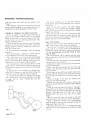
'HÄ,LF SHAFT UNIVERSAL JOINTS
Grease nipples (see the 3.8 "E" Type Service
Manual-Page H8-Early cars) were reintroduced
from the corrurenoement of production of Series 2
cars.
to the nipples of the outer joints is gained
by removing the plastic sealing plugs from the joint
covers. The universal joints should be greased every
Access
6,000 miles (10.000 km.).
Page HY.s.1
sEcTtoN
I
STEERING
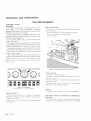
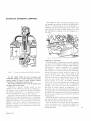
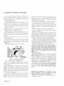
GENERÄL DESCRIPTION
The upper and lower steering columns
and the
mountings are of the collapsibt. typ.
designed to
comply with the U.S.A. Fede¡al Saiety
Regulations,
.The collapse points. are retained by nylon plugs
which will shear
wheer and
,
forward.
..1;.;l ¿ffii ;':"itr.i.,",,îïîå
NO ATTEMpT must be made to repair
the units
to accident.
NEW replacement items MUST be
fitted.
il^ damaged due
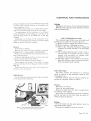
UPPER. STEERING COLUMN
IÞscription
The upper steering column (inner)
is composed ol
stiding shafrs retained io a fixed
lengrh
ï"_:.:f1.":.
oy
nyton plugs, the outer coiumn being pierced
iã a
lattice lorm.
The inner shaft assembly rs supported
in the outer
column by two pre_lubricaied tape;
,olt..'U.oringr.
A gaiter covers the pierced portion oi the outer
column to seal against the ingreis
ol dirt.
Removal
Disconnect the batterv.
Withdraw the sell-taiping screws
and remove the
under-scuttle casing aUoue ttre steering
.oiurn".
Disconnect the cables contained
iã tfr. direÒtion
indicator switch harness.
Note the location ol the connections
for relerence
when refitting.
. Withdraw the ignition key, remove the ring nut and
detach the ignirion swirch from rhe
mountì;; bracket
on the steering column.
Note
: If
the car is fitted with air_conditioning equip_
ment the switch will be mounted on a bracket
aitached to the evaporator unit and need
be removed.
Release three grub screws
not
in the steering wheel hub
and remove the steering wheel motif.
Remove the locknut, hexagon nut and flat
washer
and withdraw the steering wheel irom the
splines on
the inner column.
Disconnect the cables from the steerin-q column
lock (if fitted). Nore the location of the ãables
for
reference when refitting.
Remove the nut, lockwasher and pinch bolt securing
the upper universal joint to the lou,er steering column.
Remove two nuts and lockwashers securing
the
upper column lower ntounting bracket to the
under_
side of the scuttle.
Remove two bolts, nuts, locku,ashers ancj
distance
pleces securing the upfrer mounting
bracket to the
support bracket on the body.
.
Withdraw the upper.column lrom the splines
on the
.lower column.
Note
: If
the steering column has not been dantaged
by impact, i.e., if the nylon plugs in the inner
column or the top mounting bracket have
not
sheared, excessive lorce must NOT
be used to
separate the upper universal joint from
the
lower column.
Refitting
Refitting is the l.everse ol the l.emoval procedure.
Set the road wheels in the straight aheaã position
and check that the bolt holes in the lugs
of the upper
column universaI joint regtster corrãctly
with the
groove machined in the lower column
splines. Tighten
the pinch bolt to a torque ol l6_lg lb. fi.
|2.Z_Z.S kgnt¡.
IMPORTANT
Excessive force as notecl under .Removal,
must not
be used when reassembling the l,niversal joint
to the
column.
UNDER NO CIRCUMSTANCES should a
mailer
or similar tool be used when engaging the splines
in
the joint and column.
Il the splines wilI not engage freely, inspect lor
danrage or burrs and remove with a fine
file.
NO ATTEMpT must be made to repair any nylon
plugs which have sheared drre to impaát.
Dismantling
Dismantling is confined to removing the
steering
column adjuster locknut, the splined ihaft
and the
direction indicator switch as detailed on page
I.g.
LO\ryER STEERTn-G COLUMN
Description
Iou,er steering column comprises two sliding
,TJre
shalts retained to a fixed length by nylon plugs.
Page IY.s.l
STEERING
II\TPORTA\T
Removal
Rcntovc
tltc
tt1'rpcr stecritrs
coll'tlltl as
dctailcd
prcviouslY.
Renroric the
lltlt. locks'ashcr alld bolt seculirlg thc
colunrn to thc loucr tttlivcrsal joint and *ithdrar.l'the
colurltt rearr¡ at-ds tll roLrgh the grotl-ttt-tct'
Note : llthe stcering colull,t.t has t.tot been darlraged by
impact, i.e., il the nylorl plugs ilr the colulrlu
have not shealecl, excessive force must NOT be
trsed to separate the colurnn ancl the lower
universal joilrt'
Refitting
Refitting is the reverse ol the removal procedure'
Check that the bolt lioles in the urlivelsal joirrt
registel correctly with the groo\/e nlachincd in the
colunru splines. Tighten the pinch bolt to a torqtlc
of 16 - I 8 lb. ft. (2.2 - 2.5 kgn).
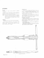
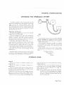
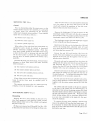
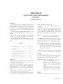
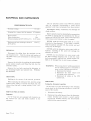
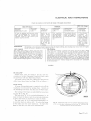
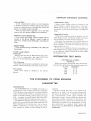
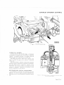
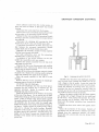
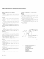
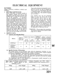
Fig
Page IY.s.2
l.
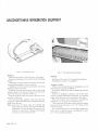
Sectiotterl tie*'
Erccssiic lorcc as rlotcd utldcr 'Rctltor ltl' lrltl:i ¡ltlI
be uscd ii hcrr reassetlbling thc ullire-r:al jolrlt to thc
colunru. Uì-DER NO CIRCUI\ISTA\CIrS rltoultl
a rn¿illct or silllilar tool bc ttscd rthcn crrgltgirrg tirc
splines in the joint or thc colLrllltl.
ìl the splines s'ill not cngagc hccl)'. ilì\pùcI l'or'
danrage or burrs and carc-lully l'crrlovc ri ith n lìllc fìlc.
NO ATTEMPT must be nrade to rcpair any rr¡'lotr
plugs u'hicli have sheared due to inrpact.
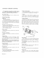
STEERING HOUSING
The rack and pinion assembly is identical to that
shown in Fig. 3-page 15 of the 3'8 "E" Type
Service Manual with the exception of the rack preload cor::ponents.
The betleville washer and disc are replaced bY a
spring and retaining caP.
The method of adjustment and the rack and float
figure remain as stated on Page 17.
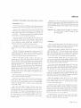
of tlrc.ttppcr attd lor¿t
sltot'irtg llta n¡lort Plttgs'
slcct ¡ttg coltttttttt
I3t67
sEcTtoN
rl
STEE RI N G
(Power assisted)
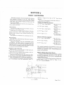
DESCRIPTION
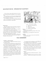
The power-assisted steering system, available as optional equipment, consisls of three main components; the
rack and pinion steering unit, the pump, and the reservoir interconnected by flexible hoses.
The pump is mounted on the left-hand side of the engine, the reservoir being attached to brackets secured to
the left-hand sub-frame.
A shield protects the ¡eservoir on left-hand drive cars from the exhaust manifold heat.
The upper and lower columns remain the same in detail as stated in Section I, page IY.s.l,
Adwest Engineering Co. Ltd.
Type
Rack and Piniori
.
Number of turns-lock to lock
Turning circle
Hobourn Eaton
Left-front of engine
Operating Pressure
F¡ont Wheel Alignment
1,000Ib./sq. in. (70.3 kg./cm.z)
++'
(1.6-3'2 mm.) toe-in
.
Page IIY.s.l
STEERT
NG
(POWER-ASS|STED)
OPERATION
STEERING GEAR
Oil is supplied from the reservoir via the output
side of the pump to the steering unit (pressure hose)
and is then returned from the steering unit to the
reservoir (return hose).
A continuous flow of oil is pumped through the
system whilst the engine is running but pressure
builds up only when the steering wheel is turned'
The steering gear is basically a normal rack and
pinion manual steering with a torsion bar controlled
iotary value embodied in the input shaft and a
hydraulic cylinder.
The piston in the hydraulic cylinder is connected
to the rack.
Steering lock stops are incorporated
in the gear
These grooves lie between three grooves in the
valvé sleeve when no load is applied to the steering
wheel, the rotor being centred in the sleeve by a
torsion bar.
When steering effort is applied at the wheel, this
is transmitted via the torsion bar to the rotor. The
torsion bar is, however, slender and the manual effort
causes it to twist, thus allowing the rotor to rotate
in the
THE PRESSURE PUMP
The pressure pump is a roller type, belt driven unit'
unit.
THE VALVE UNIT
sleeve.
The relative movement of the grooves in the rotor
to the grooves in the sleeve allows hydraulic pressure
from the pump to operate on either side of the piston
thus assisting the movement of the rack'
This is a rotary type control valve. The valve rotor,
which is also the input shaft to the steering gear, has
three grooves machined in it.
The relief valve is set to operate between 950 and
2). The flow
1,000 lb./sq. in. (66'8-70'3 kg.lcm
control valve is set at2'2lmp. galls. per min. (10 litres/
min.) (21 U.S. pints Per min.).
on an exchange
No servicing or adjustment is possible with the pump. Replacement units can be obtained
from:THE SPARES DIVISION,
JAGUAR CARS LTD.,
COVENTRY,
ENGLAND.
Page IIY.s.2
basis
STEER!
NG
(POWER-ASS|STED)
SERVICING
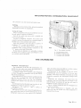
Checking The Reservoir Oil Level
The oil reservoir is mounted on the right_hand side
of the engine. It is important that absolute cleanliness
is observed when replenishing with oil as any foreign
matter that enters may affect the hydraulic system.
Remove the filler cap, check the oil level arid top
up if necessary with the recommended grade of fluid.
The correct level of the oil is just above the filter
of the ball housing to see if they have become displaced or split. In this event they should be repositioned or replaced as any dirt or water that
enters th'e joint will cause premature wear.
Do not over-lubricate the ball joints to the extent
where grease escapes from the rubber seal.
element.
Rack and Pinion Housing
The rack and pinion housing is attached
to
the
front suspension crossbeam.
A grease nipple, located in the rack adjuster pad
for the lubrication of the rack and pinion assembly,
is accessible from underneath the front of the car
from the driver's side.
Check that the clips at the ends of the bellows are
fully tightened, otherwise the grease will escape from
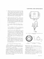
Fig.
1.
the housing.
Steering Tie-Rods
nts of the two steering tie-rods
lubrícant. When carrying out
the rubber seals at the bottom
Front Wheel,A.lignment
Check the front wheel alignment as detailecl on
page IIY.s.9. if uneven wear is evident on the tyres.
CHECKING AND ADJUSTMENT ON CAR
The following adjustments can be carried out on
the car; all others which may cievelop require the
removal of the unit from the chassis.
RACK RATTLE
This is usually apparent when traveiling on rough
surfaces.
Adjust as follows:-
(1) Release the locknut retaining the rack pad
adjusting screw.
(2) Screw the rack adjusting screw until a firm
resistance is felt, and back off Sth of a turn
(221") maxrmum.
Firmly grip the bail pin arm protruding from the
pinion end of the steering gear and by moving it
towards the rack back-up pad, a spring resistance
should be felt.
The total amount of play at the rack pad should
not exceed .010' (.254 mm.). Check by removing
the grease nipple and inserting a dial indicator
through the rack pad and rack adjusting screw until
the stem contacts the back of the rack. By pulling
the raok against the spring the total amount of end
play can.be measured.
If the spring resistance
is negligible, remove
the
Page IIY.s.3
STEERT
NG
(POWER-ASSTSTED)
rack pad screw and check that the spring is not
broken.
The clearance should be the minimum that will
allow smooth operation of the steering unit with no
binding at any point tåroughout the full travel.
STEERING VEERING TO RIGHT OR LEFT
the car steers to the right or left when being
driven in the straight ahead position, or if unequal
efforts are required to turn the steering to the right
or left, carry out the following preliminary tests
If
before proceedihg further :Check the tyre pressures and tyre wear and change
the front tyres from one side to the other. If the pull
changes direction, then the trouble lies with one or
both of the front tyres.
tf the pull remains unchanged, check the steering
geometry,
If no improvement is apparent, the fault must be
in the trimming of the valve in the steering unit.
Fit a 100 lb. per sq. in. (7 kg./cm.z) pressure gauge
in the return line, start engine and allow to idle'
Note the pressure gauge reading which should be
40Ib. per sq. in. (2'8 kg.lcm.2) approximately.
Turn the steering to the left and right by a smalf
equal anrount. The pressure should increase by an
equal amount irrespective of the direction the steering
is turned.
If the pressure is not balanced as indicated by a
slight fall in pressure on one side before rising, the
valve and the pinion assenrbly must be replaced'
If, on stariing tlie engine, the steering kicks to one
side, replace valve and pinion assembly as detailed
on page IlY.s.6, under "Dismantling and Re'
assembling".
The pinion asìembly can be removed without
detaching the rack housing assemblY from the car,
if
necessary.
Back
off the rack adjuster Pad fullY
before
removing the pinion housing and readjust to glve
.010' (.254 nrm.) end play as detailed under "Rack
Rattle" after refi tting.
Note the position of the pinch bolt slot in the
input shaft before removing, and ensure that the slot
is in the same position after refitting. Allow for the
spiral in the pinion when reassembling,
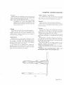
BÄLL PIN KNOCK
Ball pin knock, evident when turning to left or
right, is due to wear in the inner ball assembly'
fnis will only be apparent after long periods of
service, and on tlo account must any adjustment be
attempted to reduce wear which may have developed'
A new ball pin/track rod assembly must, in ALL
cases, be fitted.
The new assembly will be supplied less the outer
ball pin and bellows which must be ordered separately
if required.
'r¡i Ualt pin/track rod assembly can be removed
with the raçk in situ as follows:Disconnect the track rod on the side to be removedt
from the steering arm.
Remove the bellows retaining clip from the rack
housing. Fold the bellows back until the inner ball
joint
is exposed.
Knock back the ears of the tab washer which locks
the inner ball joint assembly to the rack shaft, remove
the ball joint and track rod as a unit and collect thë
sprlng.
Chãck the length of the track
inner and outer ball Pin centres.
rod between
the
Release the outer ball joint locknut, remove the
joint and nut and withdraw the bellows after releasing
the clip.
Check the outer ball joint and replace if necessary'
Re-assemble to the track rod and adjust the length
between the ball pin centres to the figure as noted on
iemoval. This should be 8'75" (22'2 cm')' IT IS
IMPORTANT that both track rods are of equal
length.
Refit ttt" inner ball joint and spring to the rack
shaft and tighten fully. Secure with new tabwasher'
Apply a generous coating of the recommended
grade of grease to the inner ball housing and reût the
bellows and tighten the cliPs.
Reconnect the track rod to the steering arm and
front wheel alignment as detailed on page'
'check the
llY.s.9,
Fie.2.
Page
IIi.s.4
STEERt
NG
(POWER-ASStSTED,¡
CHECKING THE HYDRAULIC SYSTEM
A number of faults in the steering system can be
by ineffciencies in the hydraulic circuit, see
page llY.s.t0 for "Fault Finding" chart. The
caused
following checks can be carried out without removing
any components from the car. Before starting any
of this work the fluid should be checked for correct
Ievel and for lack of froth.
Pump Blow Off Pressures
Fit a pressuie gauge into the return line, start.thè
bngine and run at idling speed.
Turn the steering to full lock and continue to
increase the steering wheel effort until the pressure
ceases to increase. The peak pressure should lie
between 950 and 1,000 lb./sq. in. (66.8-70'3 kg./cm.2)
and should not increase with engine r.p.m.
If however, the pressure is below 950 lb./sq. in.
(66.8 kg./cm.z) at tickover but rises to the correct
figure with increased engine speed, then the trouble
is caused either by a faulty ¡elief valve in the pump
or by excessive internal leakage in the steering gear.
Fit a pressure gauge into the pressure line with an
"ON-OFF" tap in series with the gauge and the
steering unit.
Fig.
3.
If the pressure does not fise to this figure close the
tap for a maximum of 5 seconds and note the gauge
reading. This should be 1,000Ib./sq. in. (70.3 kg./om.z)
valve pressure.
-relief
If this reading is obtained, the leaks are confined
to the steering unit which shor.rld bè removed and
overhauled.
If
the reading is not obtained the fault
lies in the pump.
Faulty pumps cannot be serviced. New replacement units can be obtained on an exchange basis
from:The Spares Division,
Jaguar Cars Ltd.,
Start the engine, open the tap and lurn the steering
to full lock. Check the pressure reading on the gauge.
This should ¡ead ì,000Ib./sq. in. (70.3 kg.lcm.z).
Coventry,
England.
STEERING GEAR
Removal
Remove the bonnet as detailed in Section
page NY.s.3.
Remove the radiator as detailed in Section
PaBe DY.s.1.
N_
track rod ball joints from the steering levers using
C_
Remove the bolts, nuts and washers securing the
unit to the frame assembly as detailed
under "Steering Housing-Removal", on page I,6
and withdraw the unit.
Note: If the steering column has not been damaged
by impact, i.e. if the nylon ilugs in the column
have not sheared, excessive force must NOT
be used to separate the pinion shaft and the
lower universal joint.
Tu¡n the steering wheel until the Allen screw in
the lower column universal joint is accessible, insert
an Allen key and remove the screw.
Disconnect the hoses from the steering unìt and
catch the oil which wilt drain away. Blank off the
connections and unions to prevent the ingress of dirt.
Remove the nuts and washers and disconnect the
a
suitable extractor.
steering gear
Page IIY.s.5
STEERT
NG
(POWER-ASSTSTED)
(c) Knock back the tab washer securing the inner
to the rack housing. Remove three
nylon locking nuts retaining valve body assembly to the rack housing. Withdraw the assembly
and discard the joint. Note the location of the
pinch bolt slot before withdrawing the housing.
The unit is now separated into its two major
components, that is, valve and pinion assembly
and the rack and tube assembly.
Þepending on the fault, either of these or both
can be dismantled and the faulty component
ball pin to the rack shaft.
Remove the inner ball pin and track rod as a
unit. DO NOT dismantle the ball pin assembly.
Collect the thrust spring and spacer.
(d) Release the locknut retaining the rack adjusting
pad screw, remove screw, spring and pad.
Ðo not disturb the outer ball joints unless these
are to be removed for replacement. If the ball joints
are removed for any purpose, check the total length
of the tie rods befbre releasing the locknut.
Tie rods must be re-assembled to an equal length
relation
Dismantling
Thoroughly clean the outside of the unit before
attempting to dismantle.
Remove the sub-assemblies or components as
follows:(a) Remove the external pipes.
(b) Remove the wire clips retaining the bellows
to the stee¡ing unit and fold back the bellows
lf)
to expose the ball joints.
(e) Mark the location of the pinion housing in
replaced.
af
8'75" (22'2 cm.).
EXAMINATION OF COMPONENTS
'Valve anrl Pinion/Housing Ässembly
The vaive and pinion/housing assembly will be
available for Service Replacement purposes as a
complete unit only, with the exception of the top
seal and the associated back-up seal, the housing
gasket and the pipe union seats.
With the assembly ¡emoved from the rack tube,
carry out the following checks:-
With a soft mallet drilt out the valve and pinion
assembly from the housing.
Examine the teflon rings. These should be a loose flt
in their grooves and fhe outer diameter should be free
from cuts, scratches or similar blemishes.
Ensure that there is no relative movement at the
trim pin between the valve sleeve and the shaft.
Check that there is no wear in the torsion bar
seals.
Replace with the new seals contained in the seal
kit and refi.t the circlip.
Reflt the shaft assembly and reassemble the housing
to the rack tube with a new gasket.
Renewing the Pipe Union Seats
If worn or damaged, the pipe union seats can be
renewed by tapping a suitable thread in the internal
bore of the seat and inserting a setscrew with an
attached nut and plain washer.
Tighten down the nut against the housing base and
withdraw the seat.
Fit new seat by ìnserting in the housing and tapping
home squaæ with a soft drift,
assembly pins by ensuring that there is no free movement between the input and output pinion shafts.
Examine the housing bore for signs of wear,
particularly on the rubbing surfaces of the teflon
Rack and Rack Housing
The following items will be available as replace'
rings.
ment
Examine the needle roller bearings for damage or
'wear.
If, during the above checks, any fault is found,
the
complete assembly must be replaced as a unit.
Replacing the Top Seal
Drift out the shaft assembly as detailed above.
Remove the circlip and extract the top and back-up
Page IIY.s.6
1.
2.
3,
4.
parts:Rack
Rack Housing
"Clevite" Bearing
Seal (contained in Seal Kit).
Replacement rack housings will be complete with
end cap, seals, "Clevite" beari4g and needle beaÅnj.
I Remove the valve and pinion housing as detailed
previously.
I
STEERTNG (POWER-ASSISTED)
Mark the location of the end cap in relation to the
rack tu-öing.
Unscrew the ring nut retaining the end cap to the
rack tube and withdraw the cap.
Remove the union from the rack tube and push
out the centre seal housing from the pinion housing
Check that the pinch bolt slot is in the same relative
location as noted on removal when engaging the
pinion with the rack teeth.
Allow for the spiral in the pinion assembly when
reassembling. Fit the self-locking nuts and tighten
.down evenly.
rnd of the tube.
Check the condition of the piston and ring and
if
worn or scratched renew complete.
Remove the outer circlip and withdraw the piston.
Note any shims which may be fitted between the
inner circiip and the piston.
Remove the "O" ring from the shaft and replace
with the new part contained in the Seal Kit. Refit
the piston and secure with circlips.
Check that end float between piston and circlip
does not exceed '010'. If this condition exists reduce
,end float by adding a shìm.
IMPORTANT: Check that the piston rotates freely
between the circlips on completion.
Remove the "O" rings and seal from the centre
seal housing and discard. Replace with new parts
.contained in the Seal Kít.
Insert the housing into the tube with the lips of the
seal facing towards the centre.
Line up the hole in the housing with the hole in the
tube and secure with the union.
Insert the rack in the rack housing. Extreme care
must be taken to ensure that the oil seal in the housing
is not damaged by the rack teeth.
Remove the "O" ring and oil seal from the end
cap. Check the condition of the "Clevite" bearing
and replace if worn or damaged with a new bearing.
A mandrell machined to the internal diameter of the
bearing should be used when refitting to prevent the
bearing collapsing.
Renew the oil seal and "O" ring and refit the end
cap. Line up the location marks made during removal
and secure with the ring nut. Care must be taken to
ensure that the end cap does not turn when tightening
the ring nut. Any movement will place the mounting
brackets out ofphase with each other.
Reflt the rack adjuster pad, spring, adjuster screw
and locknut, but do not attempt fo c,arry out any
rack adjustment at this
marked on removal.
stage.
Refit the inner ball joints and track rods as an
assembly as detailed on page f IY.s.4 under "Ball
Pin Knock",. If the inner ball joint is to be replaced
,due to weaÍ, a new unit complete with track rod
must be obtained. ADJUSTMENT OF THE
JOINT IS NOT PERMISSIBLE.
Refit the outer ball joints if removed; adjust the
length of each track rod to 8'15'(22.2 cm.) between
the ball joint centres. IT IS IMPORTANT that the
track rods are of equal length.
Adjust the rack back-up pad as detailed on page
.llY.s.3.
Refit the grease nipple and the external pipes.
Coat both rack ball housings with 2 oz. (56.7
gramn.res) of the recommended grade of grease, fit
the beilows and secure with the clips to the track rod
and steering housing.
Apply a grease gun to the nipple in the back-up
I oz. (28.35 grammes) of the
adjuster pad and inject
recommended lubricant.
Do not lubricate the housing to the extent where
the bellows become distended. Over-lubrication may
also block the air transfer pipe.
Refitting
Refitting is the reverse of the removal procedure,
Reconnect the high and low pressure hoses, care
being taken
to
ensure
that the
connections are
perfectly clean.
Ref,t the lower and upper steering colurnns
as
detailed on page illY.s.8
Refill the reservoir to the full mark of the dipstick
with the recommended grade of Automatic Transmission Fluid.
Bleed the system as follows:(a) V/ith the engine running, turn the steering from
lock to lock a few times to expel any air which
may be present, indicated when all lumpiness
,
has disappeared.
Final Assembly
Place a new seal joint over the three studs in the
raok housing.
Refit the pinion housing, noting the position
as
(b) Check the fluid level in the reservoir and top
up if necessary with the recommended grade
of fluid. The correct level is just above the
filter element.
Page IIY.s.7
STEERI
NG
(POWER-ASSISTED)
STEERING COLUMN
The upper and lower steering columns and mountings are of the collapsible type designed to comply
with U.S.A, Federal Safety Regulations.
The collapse points are retained by nylon plugs
which will shear on impact, allowing the steering
Wheel and columns (upper and lower) to move
forward.
NO ATTEMPT must be made to repair the units
ìf damaged due to accident. NEW replacement items
MUST be fitted.
UPPER STEERING COLUMN
Description
The upper steering column (inner) is composed of
two separate sliding shafts retained to a fixed length
by nylon plugs, the outer column being pierced in a
Iattice form.
The inner shaft assembly is supported in the outer
column by two pre-lubricated taper roller bearings,
A gaiter covers the pierced portion of the outer
column to seal against the ingress of dirt.
Removal
Disconnect the battery.
. Withdraw the self-tapping screws and rernove the
under-scuttle casing above the steering column.
Disconnect the cables contained in the direction
indicator switch harness.
Note the iocation of the connections for reference
when refitting.
Withdraw the ignition key, remove the ring nut
and detach the ignition lock from the mounting
bracket on the steering column,
Note: If the car is frtted with air.conditioning equipment, the switch will be mounted on a bracket
attached to the evaporator unit and need not
'
be removed.
If
the car is fitted with a steering oolumn lock,
removal of the lock will not be possible, and it will
be necessary to disconnect the attached cables at the
snap connectors.
Release three grub screws in the steering wheel hub
and remove the steering wheel motif,
Remove the locknut, hexagon nut and flat washer,
aird withdraw the steering wheel from the splines on
the inner column.
Remove the nut, lockwasher and pinch securing
bolt the upper universal joint to the lower steeridg
'oolumn.
Page IIY.s.8
Remove two nuts and. lockwashers securing the
upper column lower mounting bracket to the under-
tide of the scuttle.
Remove two bolts, nuts, lockwashers and distance
pieces securing the upper mounting bracket to the
support bracket on the body.
Withdraw the upper column from the splines on
the lower column.
Note: If the steering column has not been damaged
by impact, i.e. if the nylon plugs in the inner
column or the top mounting bracket have not
sheared, excessive force must NOT be used to
separate the upper universal joint from the
lower column.
Refitting
Refitting is the reverse of the removal procedure.
Set the road wheels in the straight ahead position
and check that the bolt holes in the lugs of the upper
column universal joint register correctly with the
groove machined in the lower column splines.
Tighten the pinch bolt to a torque of 16-18 lb' ft.
(2.2-2.s kem.).
IMPORTANT
Excessive force as noted under "Removal" must
not be used when reassembling the universal joint to
the column.
UNDER NO CIRCUMSTANCES should a
mallet or similar tool be used when engaging the
splines in the joint and column.
If the splines will not engage freely, inspect for
damage or burrs and remove with a fine file.
NO ATTEMPT must be made to repair any nylotl
plugs which have sheared due to impact.
Dismantling
Dismantling,is confined to removing the stediing
column adjuster locknut, the splined shaft and the
'direction indicator switch as detailed on page llY.s.8:
LOWER STEERING COLUMN
Description
steering column comprises two sliding
shafts retained to a fixed length by nylon plugs.
Ihe lower
Removal
Remove the upper steering column as detailed
STEERt
previously.
Remove the nut, lockwasher and bolt securing the
column to the lower universal joint and withdraw the
column rearwards through the grommet.
Note: If the steering column has not been damaged
by impact, ji.e. ,if the nylon plugs in the
column have not sheared, excessive force must
NOT be used to separate the column and the
lower universal joint.
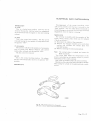
FRONT WHEEL ALIGNMENT
It is ESSENTIAL that the lollowing instructions
are carried out '.vhen checking the front wheel alignment, otherwíse steering irregularities may result.
Important
Inffate all tyres to the recommended pressures.
Each wheel must be adjusted individually by means
of the tie-rods to give half the total toe-in olfi, to {,
(l'6 to 3.2 mm.).
Pri¡cedure
Set the
Refitting
Refitting is the reverse of the removal procedure.
Check that the bolt holes in the universal joint
register correctly with the groove machined in the
column splines. Tighten the pinch bolt to a torque of
16-18 lb. ft. (2.2-2.5 kgm.).
front wheels in the straight ahead position.
Centralise the steering by removing the grease
nipple from the rack adjuster pad and inserting the
centralising tool (Jaguar Part No. 12297).
Check the alignment of the front wheels by using
light beam equipment or an approved tract setting
gauge.
IMPORTANT
Excessive force as noted under "Removal" must
not be used when reassembling the universal joint to
the column. UNDER NO
NG (POWER_ASSISTED)
If adjustment is required, slacken the locknuts at
the outer end of each tie-rod, release the outer clips
securing the rack housing bellows to avoid distortion
after turning the tie-rods.
CIRCUMSTANCES
should a mallet or similar tool be used when engaging
the splines in the joint or the column.
If the splines will not engage freely, inspect for
damage or burrs and carefully remove with a fine file.
Turn the tie-rods by an equal amount in the
necessa¡y direction until the alignment is correct.
Tighten the locknut and re-check,
Ensure that the bellows are not twisted and tighten
the clips.
REMOVE THE CENTRALISING TOOL and
refit the grease nipple to the rack adjuster pad.
NO ATTEMPT must be made to repair any nylon
plugs which have sheared due to impact.
ffitu
=rLiil;,ffif-_=l
Fie. 4.
Page IIY.s.9
FAULT F¡NDING CF{ART
External oil leaks from Rack and
Pinion unit,
REMEDY
POSSIBLE CAUSE
FAULT
Damage or wear
correct tightening
to
seals or inof unions or
bolts.
It is most imPortant that source ol
the leak is traced before any
attempt is made to rectifY. Once
the leak is located, tighten the
unions or bolts or rePlace the
seals as necessary.
Renew gasket.
Leak at reservoir.
Cover gasket damaged'
Hose connection loose.
Tighten hoses.
Leak at pump shaft.
Worn or damaged seals on shaft'
Replace pump.
Steering veering to right or left.
Unbalanced tyre Pressures or
faulty tyres. Steering gear out of
trim.
Check as detailed on Page IIY s'4'
Heavy steering when driving.
Low tyre
Inflate tyres.
Tightness
Pressures.
or
stiffness
aud/or steering and
in
column
Grease
or
rePläce components.
susPension
joints.
Heavy steerin! when Parking.
Loose pump belt (nearlY
alwaYs
accompanied by a squealing noise).
lnsufficient pressure from PumP
due to defective PumP valve or
restricted hoses.
Insufficient pressure due
to
high
leaks in steering gear.
Check pump belt, replace if
necessary.
Remove restriction or check PumP
pressure as detailed on Page IlY.s.5.
Replace pump if faultY.
Confirm high internal leaks. If
proven, remove the rack unit from
the car and rePlace seals.
Steering effort too light.
Worn torsion dowel Pins or torsion
bar broken.
Remove valve housing and fit new
Poor straight running.
Incorrect tyre Pressures.
Incorrect toe-in.
Inflate.
Noise from pump.
Belt loose, indicated bY squealing
Check
during parking manoeurvres.
Other pump noises are due to wear
necessary.
unit.
Check and reset as necessary'
belt and rePlace
as
Replace pump.
or damage.
Rattle when travelling on rough
Vy'ear between
roads.
assembly.
rack and
Pinion
Wear at ball joints at the ends of
the rack.
Wear in the rack housing bush.
Adjust rack pad adjuster screw
detailed on Page llY.s.3'
Renew ball joint and track rod
as
an assernbly.
Remove the rack and renew the
bush.
Page IIY,s,10
as
sEcTtoN I
FRONT SUSPENSION
Section J-page J. 15 of the 3.g .,E,, Type Service
Manual.
The correct dimensions for the hole centres for
The routine maintenance periods are increased
from
those stated previously.
Wheel Swivels
Lubricate the nipples (four per car) fitted to the top
and bottom of the wheel swivels.
A bleed hole js provided in each ball joint; The hole
being covered by a nylon washer whlch ilfts under
pressure and indicates when sufficient lubrìcant
has
been applied
setting links are as follows:_
Without air-conditionin g equipment
4.2
"8"
Sports
Type-Open
4.2 "E'r Type-F.H.C.
4'2
"8" Type-Open Sports
4.2
"8" Type-F.H.C.
4.2
"8" -lype-2+2
cm,)
L.H.D.
179i" (45.16 cm.)
L.H.D.
179|'(45.6 cm.)
R.H,D.
1711" (45.6 cm.)
R.H.D.
18$'(46.06 cm.)
L,H.D./R.H.D.
The nipples are accessible from underneath the car.
Wheel Bearings
Removal of the w_heel bearings will expose a grease
nipple in the wheel hubs.
I7!], (45.16
With air-conditioning equipment
4.2
"E" Type-Open
Sports
4.2,,8,'
Type-F.H,c.
4.2,,E,,
Type-2*2
l7!!,, (45.6
cm.)
1ri,T;?:å.;,T.i
,rl,t;?.'ri,T.i
L.H,D./R,H.D.
that the headlamps centres
TORSION BAR SETTING
Check that the car is full of petrol, oil and water
and
to U,S.A. Federal Regulations
).
that the tyre pressures are correct.
Place the car on a perfectly level surface, with
the
wheels in the straight ahead position.
the
the
in
gr
out in
are
ect height from the ground level
accordance
ied
with the instructions given in
removal, dismantling, bearing end float and
^Further
refitting
details remain as sãted on page J.13
of
the 3.8
"E"
Service Manual,
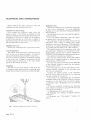
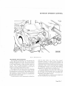
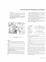
.€;
,5)
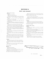
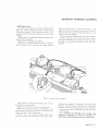
Fig. 1. The dinrcnsion for checkitry rhe
/iont sttspettston riding
(2!.ätfl;: )
^-q"
Page JY.s.1
SECTION L
BRAKES
DATA
Brake disc diameter-front
-rear
Master cylinder bore diameter
Lockhoed
P,rutlin.
Mintex M.59
Handbrake friction pad material
Mintex M.34
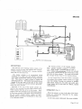
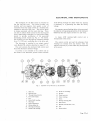
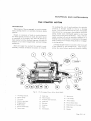
Key to Figs,
I
l. FlLrid ât feed pressure
2. Fiuid at nraster cyiinder deìivery
3. Fluid al system delivery pressure
4. Vacuun.r
5. Air at atmospheric pressure
A SÌave cylinder prirnary chamber
B Outlet port front blakes
C Inlet port for secondary piston
D Outlet port-rear brakes
E Vacuum
F Air pressure
G Diaphragnr
H Filter
I Air controì spool
J To rear brakes
K To front brakes
L Dual slave cylinder
M Servo unit
N Master cylinder
O Brake reservoirs
P To nranifold
a To ¡eservac
R Reaction valve
S Atmospheric pressure
Page LY.s.2
pres'sure
BRAKES
Dual-line servo braking syslem.
DESCRIPTION
The dual-line servo braking system consists of an
integral vacuum booster with tandem slave cylinder,
a master cylinder combined with a booster reaction
valve and two fluid reservoirs.
Ihe
booster portion
slave
tank
and a
of the integral booster
of a pressed
henolic resin
tr
A push rod, secured
to the piston, extends through the forward face of the
tank into the slave cylinder. This push rod provides
the principal motive force for the tandem pistons.
On the forward face of the boost tank is mounted
cylinder, is actuated by hydraulic pressure generated
within the main chamber.
Mounted on the end of the master cylinder, the
reaction valve consists of a pair of flow control valves
which sequence the flow of air to the booster. Both
control valves are operated by-the intermediate piston
in the master cylinder. A flat plate, interposed between
the two master cylinder pistons, .o"bl., the inter_
mediate piston to function mechanically in the event
of an hydraulic failuré.
OPERATION (Fig.
l)
When the system is at rest, both sides of the boost
system are continuously exhausted by the engine
manifold depression.
As the brake pedal is depressed, the master cylinder
Page LY.s.3
BRAKES
piston moves along the cylinder building uP pressure
and forcing.fluid out to the primary chamber of the
(A).
Simultaneously, the intermediate
piston, in the end of the master cylinder, closes the
diaphragm valve (G) in the reaction valve and, in so
doing, isolates the vacuum (E) from the air pressure
side (F) of the boost system.
slave cylinder
Further progress of the intermediate piston along
its bore will crack the air control spool (l) in the
reaction valve thus admitting air at atmospheric
pressure to the rear of the boost cylinder piston. The
air enters the system through a small cylindrical
filter (H) on the reaction valve.
The pressure imbalance, created by the admission
of air to the pressure side of the boost system, will
push the boost piston down the cylinder transmitting
a linear force, through the push rod, to the primary
piston of the slave cylinder.
Forward motion of the primary piston, supple-
SAFETY FÄCTORS
In the event ol a fluid line failure in the pipe linking
the master cylinder to the slave cylinder or the pipe
linking the master cylinder to the fluid supply tanks,
the reaction valve will be actuated mechanically by
the master cylinder piston providing the
booster
pressure to the lront and rear bra\es'
A failure in thefluidlinecoupling the slave cylinder
brakes will result in the slave cylinder
secondary piston travelling to its fullest extent, down
the bore. This has the effect of isolating the rear
brake line from the rest of the system and permitting
normal fluid pressure to build up in the front brake
to the rear
line.
If a fault exists in the front brake
cylinder piston
will
line, the slave
bore until it
the
along
travel
contacts the other piston and the two pistons will then
travel along the bore together to apply the rear
brakes.
mented by the output of the master cyiinder, transmits
hydraulic pressure to the secondary piston (C) and
fluid under pressure flows simultaneously from the
two output ports (B and D), to the front and rear
In the case of leaks in either the air or vacuum
pipes both front and rear brakes may still be applied
brakes.
pressure.
by the
displacdment
of fluid at master cylinder
REMOTE SERVO AND SLAVE CYLINDER
Removal
Remove the trim on the floor recess panel on the
left-hand side of the car. This will disclose the three
nuts securing the remote servo to the bulkhead.
Withdraw the three nuts.
Drain the fluid from the
sYstem,
Disconnect the four brake pipe unions and the two
Remove the battery and carrier bracket for the
battery tray.
'Withdraw the bolt securing the slave cylinder to the
mounting bracket on the outer side member' Remove
the servo together with the slave cylinder.
Refitting
Refitting the servo is the reverse of the removal
procedure. Bleed the system after replenishing with
fresh fluid.
flexible hoses.
MASTER CYLINDER AND REACTION VALVE
Removal
Drain the fluid from the system. Disconnect the
two hydraulic pipes f,rom the master cylinder' Diséonnect the vacuum hose from the reaction valve'
; Remove theclevis pin, which is retainedbyasplitpin'
socuring the brake pedal to the master cylinder push
rod from inside the car. In the case of right-hand
drive çars, remove the top of the air cleaner and rePage LY.s.4
action valve prror ro removing the two nuts securing
the master cylinder to the mounting.
On left-hand drive cars the master cylinder and
reaction valve can be removed as a complete unit.
Refitting
Refitting is the reverse of the removal procedure.
Bleed the system after replenishing with fresh fluid.
BRAKES
SERVICING THE UNTT
Turn the end cover in an anti-clockwise direction
until the indents in the servo shelt line-up with the
small radii around the periphery of the end cover,
General
Prior to dismantling either the remote ser,¡o or the
master cylinder reaction valve assembly, it is advisable
to obtain repair kits containing all the necessary
rubber parts required during overhaul. Three separate
repair kits are available as follows:-
(a) Remote servo replir kit.
(b) Reaction valve
(c)
Master cylinder repair kit.
assembly.
Examine all metal parts for damage, with particular
reference
to
those listed below and make renewals
where necess ary
i-
(b) the master
cylinder piston and bore.
servo push rod stem.
If any of the vacuum
in
hose connections have become
service these must be rectified
prior
to
reassembly.
if
Extract the seal (19) and bearing (18) from thc
mouth of the slave cylinder bore which will permit thn
removal of the push rod (9) together with the slavc
cylinder piston assembly.
The push rod may be separated from the piston by
sliding back the spring steel clip (6) around the piston
Unscrew and remove the fluid inlet connection (3)
and extract the piston stop pin (30) from the base of
the inlet fluid port. To facilitate this operation, apply
gentle pressure to the secondary piston (4).
the servo slave cylinder pistons and bore.
(d) the
Bend down the tabs on the locking plate (16) and
remove the locking plate, abutment plate (17) and
servo shell (14) from the slave cylinder by unscrewing
and removing three screws (15).
and removing the pin (5). It is not necessary to
remove the cup (21) from the piston as a new piston
together with a cup are contained in the repair kit.
(a) the reaction valve piston and bore.
loose
Remove the diaphragm (1 l) from its groove in the
diaphragm support (10) and, with the servo removed
from the jaws of the vice, apply a gentle pressure to the
diaphragm support and shake out the key (12).
The diaphragm support (10) and diaphragm support
return spring (8) can then be removed.
repair kit.
When either of the units have been dismantled the
component parts should be washed in denatured
alcohol (industrial methylated spirits). parts that
have been washed should be thoroughly dried using
a clean lint-free cloth or pressure line and then laid
out on clean paper to prevent dirt being assembled
into the servo or master cylinder and reaction valve
(c)
Remove the end cover from the servo,
The vacuum non-return valve is a sealed unit and,
faulty, it must be replaced by a new assembly.
Tap the open end of the slave cylinder body with a
hide or rubber hammer to remove the secondary piston
together Ì\,ith the piston return spring (28) from the
bore.
The rubber seal (25) located in the groove adjacent
to the heel of the piston may be removed but it is
advisable to first remove the spring retainer (26) from
l'HE REMOTE SERVO (Fig.2)
the piston head extension before attempting to ¡emove
the seal (25) and piston washer (24). Removal of the
Dismantling
plastic spiing retainer (26) is sometimes difficult but,
as a new one is provided in the repair kit, this part
Support the servo slave cylinder in the jaws of a
vice, shell uppermost, with specially formed wooden
blocks placed either side of the cylinder and against
the jaws of the vice.
Fit the cover removal tool (Churchill Tool No. J.3l)
secure it by fitting the three nuts.
to the end cover and
should be replaced,
To remove the trap valve assembly, unscrew and
(l) from the fluid outlet port. If
it is necessary to remove the shim-like clip from the
remove the adaptor
body of the trap valve Q9) ensure that this part is not
distorted in any rvay.
Page LY,s.5
BRAKES
@@
o
Ë
Ø
(ÍÐ
I
@
@
@
I
@,
@
@
.^e
(t
@
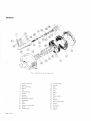
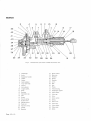
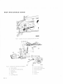
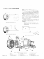
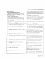
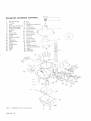
Fig. 2. Exploded view of the rcnrcre setvo.
1. Outlet connection.
2. Gaskef
3. Inlet connection.
4. Piston.
5. Pin.
6. Retaining clip.
1. Gasket.
8. Spring.
9. Push rod.
10. Diaphragm support.
11. Diaphragm,
12. Key.
13. Cover.
14. Vacuum cylinder shell.
15. Screw.
16. Locking plate.
.
Page LY.s.6
17. Abutment
18.
plate.
Bearing.
19. Seal.
20. Spacer.
21. Cup.
22. Piston.
23. Cup.
U.,
Piston washe¡.
25. Seal.
26, Retainer.
27. Slave cylinder body.
28. Spring.
29. Trap valve.
30. Stop pin.
3l
.
Gasket.
BRAKES
Assembling
Using fingers only,
Assemble the trap valve (29) complete wìth spring
and clip into the outlet port and secure ìt by frtting
the fluid outlet adaptor (l) together with the copper
gasket (31).
Prior to further
assembly,
lightly coat the four
rubber seals to be replaced in the slave cylinder bore
with Lockheed Disc Brake Lubricant.
Locafe the piston washer (24) over the piston head
extension, convex face to¡,ards the piston flange and,
using the fingers only, assemble the two rubbe-r seals
(23 and 25) onto the piston so that their
fit a new cup (21) into the
groove on the piston so that its lip (concave face) faces
towards the piston head and assemble the piston into
the slave cylinder bore.
Insert the spacer (20), gland seal (19) and plastic
bearing (18) into the slave cylinder counterbo¡e
leaving the bearing projectìng slightly from the mouth
of the bore.
Place the gasket (7) in position on the end face ofthe
slave cylinder, using the plastic bearing as a location
spigot and fit the vacuum shell (14), abutment plate
(17) and locking ptare (16).
concave
Insert the three securing screws (15) and tighten
down to a torque of 150/t70lb./ins. (1.7-1.9 kg7- )
Press the spring retainer (26) onto the piston head
Bend the tabs on the locking plate âgainst the flats
on the three screws.
Fit the piston return spring (2g) to the secondarl,
pistorr and assemble into the slave cylinder bore,
Locate the diaphragm support return spring (g)
centrally inside the vacuum shell, fit the diaphragm
support (10) to the push rod and secure it by dropping
the key (12) into the slot provided in the diaphrãgm
faces oppose each other.
extension with both seals in position.
spring leading.
Press the piston assembly down the cylinder bore,
using a short Jength of brass bar, until the drjlled
pislon flange passes the piston stop pin hole.
Insert the piston stop pin (30) into the fluid inlet
port and secure it by fitting the inlet adaptor (3)
complete with the copper gasket (2). place the push
rod (9) in the primary piston and, with the aid of a
small screwdriver, compress the small spring within
the piston to enable the pin (5) to be inserted. prior
to fitting the pin retainer (6), it is
important to
establish that the small coil spring is loaded between
the heel of the piston and the pin. Ensure that the
pin does not pass through the coìls of the spring.
Fit the spring retainer by sliding it into position
along the piston ensuring that no corners are left
standing proud alter assembly.
support.
Stretch the rubber diaphragm (l l) into position on
the diaphragm support ensuring that the bead around
its inside diameter fits snugly into the groove in the
diaphragm support.
Ifthe surface ofthe rubber diaphragm appears wavy
or crinkled this indicates that it is not correctly seated.
To ease assembly, smear the outside edges of the
diaphragm liberally
lubricant.
with
Lockheed djsc brake
Fit the end cover using Churchill Tool No. J.31.
Note: As it is possìble to fit the end cover jn three
different positìons, ensure that the end.cover
hose connections line up with the slave cylinder
inlet and outlet ports when assembly is
complete.
Page l,Y.s.7
BRAKES
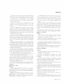
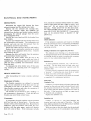
l.
2.
3.
4.
5.
6.
Diaphragm.
Screw.
Shakeproof washer.
Gasket.
Bolt.
Outlet adaptor.
64. Copper gasket.
'7. Trap valve body.
8.
9.
ro@
Washer.
10.
11.
12.
13.
14.
15,
Banjo.
Copper gasket.
Body.
Bearing,
Secondary cup.
Seal.
Piston.
--'------__
___
(9
--@
@--''t
-@
-@
@
----.-----.
152-ts-gl
Fig. 3. Exploded viex, of the masÍer cylinder and reaction valve.
16.
Return spring.
Rubber boot.
18. Spring retainer.
19. Push rod.
20. Spirolox circlio.
23.
17.
24.
25.
2t. Circlip.
28.
29.
22.
Bearing.
Page LY.s.8
26.
)1
Piston washer.
Main cup.
Retainer.
Spring.
Retainer.
Lever.
Seal.
30.
31.
Seal.
Piston.
32. Valve housing.
33. Diaphragm support.
34. Valve ¡ubber.
35. Valve cap.
36. Filter.
37. Sorbo washer.
38. Spring.
39. Filter cover.
40. Valve stem.
41. Valve rubber.
42. Valve cover.
43. Screw.
BRAKES
MASTER CYLINDER AND REACTION VALVE
Removal of the valve piston
Dismantling (Fig. 3)
Unscrew and remove the fluid outlet adaptor (6) and
extract the trap valve assembly (7) from the outlet port.
Remove the rubber boot (17) from the mouth of the
cylinder bore, compress the piston return spring (16)
and unwind the spirolox circlip (20) from the heel of
the piston. The spring retainer (18) and piston return
spring (16) can at this stage be removed.
of
(3
l)
assembly can be
effected by inserting a small blunt instrument into the
master cylinder fluid outlet port and easing the valve
piston assembly along its bore until it can be removed
by hand.
Important: No attempt should be made to withdraw
the valve piston assemhlv ¿le¡g its bore
by using pliers.
Press the piston (15) down the bore and. with the aid
special circlip pliers (Tool number 7066) extract
the circlip (21) from the mouth of the cylinder bore.
Care should be taken during this operation not to
damage the finely machined cylinder piston.
The piston assembly, complete with nylon bearings
and rubber seals, can be withdrawn from the cyìinder
bore.
Remove the plastic bearing (22), complete with ,,O"
ring (14), secondary cup (13) and rectangular section
plastic bearing (12) from the piston by sliding the
assembly along the finely machined portion.
Due to the plastic spring retainer (25) being an
interference fit onto the piston head extension, this
part is likely to become damaged during dismantling.
In view of this a new spring retainer is contained in the
appropriate repair kit. To remove the spring retainer,
hold the piston on a bench, piston head downwards,
applying a downwards force to the back face of the
spring retainer with a slim open-ended spanner. The
prston return sprinC Q6), pressed steel retainer (27)
and lever (28) may, at this stage, be withdrawn from
the cylinder bore.
Remove the filter cover (39) and collect the filter (36)
sorbo washer (37) and spring (38).
IJnscrew and remove the five screws securing the
valve cover (42), remove the valve cover assembly
from the valve housing (32) which can be dismantled
further by prising off the snap-on clip securing the
valve rubber (34).
The valve stem (40) complete with the other valve
rubber (41) can now be withdrawn from the valve
housing and the valve rubber removed from the valve
stem flange. The reaction valve diaphragm
(I)
can now
be separated lrom the diaphragm support (33) and,
by unscrewing the two
the valve
hexagon-headed scrervs (2),
housin_q can be separated
cylinder body.
from the master
Assembling
Prior to assembly liberally coat all rubber seals and
plastic bearings, with the exception ol the two valve
rubbers, with Lockheed disc brake lubricant.
Holding the master cylinder body at an angle of
approximately 25' to the horìzontal, insert the lever
(28), tab foremost, into the cylinder bore ensuring
that, when it reaches the bottom ofthe bore, the tab on
the lever-drops into the recessed portion provided.
Place the piston washer (23) on the piston head,
convex face towards the piston flange, together with a
new main cup (24) and press the plastic spring retainer
(25) onto the piston head extension.
Drop the pressed steel spring retainer (27) into the
bottom of the bore following up with the piston return
spring (26). When these two parts have been assembled
is advisable to recheck the position of the lever.
jt
Press the piston assembly into the cylinder bore and
locate the rectangular section plastic bearing (12),
secondary cup (13) and bearing (22) together with seal
(14) into the mouth of the cylinder bore.
Press the assembly down the bore to its fullest
extent and with the aid of the special circlip pliers
(Tool number 7006 with "K" points) fit the circlip
to retain the internal parts.
Locate fhe other piston return spring (16) over the
heel ofthe piston together with the pressed steel spring
retainer (18), slide the spring retainer down the finely
machined portion of the piston against the load
ol the
spring and fit the spirolox circlip (20) inro rhe groove
ground around the heel of the piston.
Using the fingers only, stretch a new valve seal (29)
and
"O" ring into position on the valve piston and
insert the assembly into the valve box.
Page LY.s.9
BRAKES
43
42
4t
40
39
38
37
3ó
28
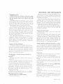
Fig.4.
1
2.
3.
4.
5.
6.
7.
8.
9.
24
of the master cylinder and reaclion
2l
valve.
Diaphragm.
23.
Piston washer.
Screw.
)^
Main cup.
Shakeproof washer.
25.
Retainer.
Gasket.
26.
Spring.
Gasket.
'r1
Retainer.
Outlet adaptor.
Trap valve body.
28.
Lever.
29.
Seal.
Washer.
10
Seal.
Inlet adaptor.
31.
Piston.
10. Copper gasket.
11. Body.
12. Bearing.
13. Secondary cup.
14. Seal.
15. Piston.
16. Return spring.
17. Rubber boot.
18. Spring retainer.
19. Push rod.
20. Spirolox circlip.
21, Circlip.
22. Bearing.
Page LY.s.10
Sectioned vieu,
26
32. Valve housing.
33.
Diaphragm support.
34.
Valve rubber.
35.
Valve cap.
36.
Filter.
37.
Sorbo washer,
38.
Spring.
39.
Filter cover,
40.
Valve stem,
4t. Valve ¡ubber.
42.
Valve cover.
43.
Screw.
BRAKES
Secure the valve housins to the master cylinder body
by fittin-u the tlvo hexa-eon headed screws (2) complete
u ith sprin-q w,ashers and tighten each screrv to a torqLte
of
I60, 180
lb. ins. (l .8 2 kglm.). A new
-sasker
shoLrld be fitted betrveen the valve hoLrsing and the
rn¿ìster cylinder body.
Stretch the reaction valve diaphrasm onto the
diaphragm support through the hole in the valve
hor.rsing so that it engages the depression in the valve
prston.
Using the fingers only, stretch the valve rubber,
which is fo¡med with the groove around its inside
diameter, onto the valve stem flange, insert the valve
stem through the hole in the valve cover and secure it
by placing the other valve rubber over the valve stem
and fitting the snap-on clip.
The valve cover assembly can now be placed into
position on the valve housing ensuring that all the
holes line up and that the hose connections are in line
with each other at the bottom of the unit. Secure the
valve cover assembly by fitting the five self-tapping
To enable new pads to be inserted it \À,ill be necessary
to lever the pistons back doivn the cylinder bores.
It is advisable to hall ernpty the brake fluid reservoirs
otheru,ise forcing the pistons back will eject fluid
l¡orr the reservoirs rvith possible resultant paint
damage.
Insert new pads. Line up the holes in the backing
plates and calioer bodies. Fjt the retaining pins and
hairpin clips: fit the anti-chatter clips to front pads.
Ensure that the pads are lree to move on the pins
to allow for brake application and automatic aCjust-
nent.
Top up the reservoirs to the correct level and apply
the brake several times until the pedal leels ..solid',.
FRONT CALIPERS
Removal
Jack up the car and remove the front wheel(s).
Disconnect the caliper ffuid leed pipe frotn the
runion and seal tlie pipe and union.
Retnove the locking wire, withdraw the mounting
bolts and lockwashers and detach thq caliper.
screws.
Hold the master cylinder in an upright position
(valve uppermost) and place the air filter together with
the rubber washer in position upon the valve cover
with the small sprìng on the snap-on valve stem clip.
Carefully locate the air filter cover over the air filter
and press it firmly home.
If the trap valve assembly has been dismantled;
insert the small clip into the trap valve body ensuring
that it does not become distorted and locate the spring
on the reduced diameter of the tr.ap valve body.
Assemble the trap valve complete (spring innermost)
into the master cylinder flLrid outlet port.
Place a copper gasket Lrnder the head of the flLrid
outlet adaptor and screw the adaptor into the fluid
outlet port. If the fluid inlet adaptor has bern removed,
this must be replaced in the same manner using a
copper gasket under the head.
The master cylinder push rod and convoluted rubber
boot can best be fitted during the installation of the
assembly.
FRICTION PADS
Renewal
Friction pads shoLrld be reneu,ed if it is found.
on visual examination through the caliper apertures,
that they have worn down to an approximate thickness
of $'(3'2 mm.).
Vy'ithdraw the hairpin clips and extract the pad
retaining pins. On front brakes, remove the antichatter clips from around the retaining pins and pad
backing plates. Withdrarv the pacts.
Locate the caliper in position and secure with the
mounting bolts and lockwashers. Lockwire the bolts
after fully tightening.
Reconnect the caliper feed pipe to the union'and
bleed the-braking system as detailed on page Ll0.
REAR CALIPERS
Removal
The rear suspension unit must be removed in orcier
to withdraw the rear calipers.
as
described in Section K ..Rear
Suspension" and support the suspension unit under
Proceed
rts centre.
Disconnect the handbrake compensator linkage
from the handbrake operating levers. Discard the
split pins and withdrar¡, the clevis pins.
Lift the locking tabs and remòve the pivot bolts
together with the retraction plate.
Remove the friction pad carriers from the caliper
bridges by moving them rearwards round the discs and
withdrawing from the rear
of the rear
suspension
assembly.
Remove the hydraulic feed pipe at the caiiper and
plug the hole to prevent the entry of dirt.
Remove .the friction pads from the caliper as
described previously.
Remove the front hydraulic damper and roaC spring
unit (as described in Section K "Rear Suspension',)
Page LY.s.l
I
BRAKES
d
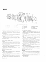
Fig. 5. Exploded view offront caliper.
l.
2,
3.
4.
5. Dust seal
6, Seal
7. Dust seal
Caliper body
Outer piston
Inner piston
10.
Clip
11. Brake bleed nipple
12. Dust cap
13. Anti-chatter clip
Seal
and remove the four self-locking nuts from the halfshaft inner r.rniversal joint.
Withdraw the joint from the bolts and allow the
hub carrier to move outwards support the carrier in
this position.
The caliper can now be removed from the aperture
at the front of the cross-member.
Refitting
Refitting is the reverse of the rernoval procedure.
Fit the ffuid supply pipe and the bridge pipe.
Bleed
the braking systeul.
THE FRONT BRAKE
DISCS
Removal
Jack up the car and reurove the road wheel. Disconnect the flexible hydraulic pipe from the frame
connection and plug the connector to prevent ingress
of dirt and loss of 1ìuid.
Discard the locking u,ire and renlove the tu,o caliper
mounting bolts. Renrove the caliper.
Relnove the hub (as described in Section J "Front
Suspension").
THE REAR BRÄKE DISCS
Removal
Renrcve the rear suspension unit (as described in
Section K "Rear Suspension").
lnvert the suspension and renrove the trvo hydraulic
damper and road spring units (as described in Section
K
8. Friction pad
9. Retaining pin
"Rear Suspension").
Renrove the fou¡ steel type self-locking nuts securing
the halfshaft inner universal joint and brake disc to
Page LY.s.12
the axle output shaft flange.
Withdravv the halfshalt frorn the bolts noting the
nurnber of camber shins between the universal joint
and the brake disc.
Knock back the tabs and unscrew the two pivot
bolts seculing the hand brake pad carriers to the
caliper. Remove the pivot bolts and the retraction
plate.
Withdraw the handbrake pad carriers from the
aperture at the rear of the cross nrembers.
Knock back the tabs at the caliper nlounting bolts.
Remove the keeper plate on the caliper and using a
hooked inrplenrent, withdraw both brake pads.
Disconnect the brake fluid feed pipe at the caliper.
Unscrew the tnounting bolts through the
holes in the brakc Cisc. Re,nove the bolts.
Withdraw the caliper- through the aperture
front ol the cross member.
access
at
the
Tap the halfshaft universal joint and brake disc
securing bolts back as far as possible.
Lift the lower u,ishbone, hub carrier and halfshalt
assembly upu,ards until the brake disc can be withdrawn lrom the mounting boìts.
Refitting
Ref;tting the brake discs is the reverse of the removal
procedure. The securing bolts must be knocked back
against the d¡ive shaft flange when the new disc has
been fitted.
Refit the rear suspension (as described in Section K
"Rear Suspension'').
Sleed the brakes.
BRAKES
¿_\\ o
ã
r?5
\t
0
3
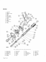
Fig.
6.
Exploded view of a rear brake caliper.
1. Rear caliper assembly (R.H.)
2. Piston
3. Seal
4, Dust seal
5. Friction pad
6. Pin
7. Clip
8. Bridge pipe
9. Bleed screw
10. Dust cap
11. Handbrake mechanism assembly
12. Pad ca¡¡ier assembly (R.H. outei)
13. Pad carrie¡ assernbly (R.H. inaer)
14. Anchor pin
15. Operating lever
16. Return spring
17. Pawl assembly
18. Tension spring
19. Anchor pin
JS P I59A
20, Adjusting nut
21. Friction spring
22. Hinge pin
23. Splir pin
24. Protection cover
25. Protection cover
26. Belt
27, Washer
28. Bolt
29. Split pin
30. Bolr
31. Retraction plate
32. Tab washer
Page LY.s.l3
BRAKES
THE BRAKE/CLUTCH PEDAL BOX ASSEMBLY
Removal (L.H. Drive)
Remove the servo vacuum pipe and clips.
Drain the brake and clutch fluid reservoirs.
Remove fluid inlet pipes from the clutch and brake
master cylinders. Plug the holes.
Remove the brake fluid warning light wires,
Remove the brake and clutch reservoirs.
Remove the fluid outlet pipes from the brake and
clutch master cylinders. Plug all holes.
Remove the brake and clutch pedal pads from inside
the car,
Remove the dash casing in accordance with the
instructions containe<Í in Section N (Body and
Exhaust). The nuts securing the pedal box assembly
to the bulkhead are now exposed and can be removed
together with two distance pieces and the brake pedal
stop plate. Note that there are six selflocking nuts
and one plain nut with a shakeproof washer. The
plain nut is located on the bottom centre stud'
Remove the brake/clutch pedal box assembly by
turning it through approximately 90' to allow the
pedals to pass through the hole in the bulkhead.
Remove the brake and clutch reservoirs.
Remove the f,uid outiet pipes from the brake and
clutch master cylinders. Piug all holes.
Remove the five screws securing the reaction valve
assembly to the valve housing and withdraw the
complete assembly. The valve housing can be removed
by unscrewing the two setscrews, together with the
shakeproof washers, which secure the housing to the
body of the master cylinder.
Remove the throttle bell crank bracket.
Remove the brake and clutch pedal pads from
inside the car.
Remove the dash casing
instructions contained
in
in
accordance
Section
with the
N (Body an<i
Exhaust). The nuts securìng the pedal box assembly
to the bulkhead are now exposed and can be removed
together with two distance pieces and the brake pedal
stop plate. Note that there are six self-locking nuts
and one plain nut with a shakeproof washer. The
plain nut is located on the bottom centre stud.
Remove the brake,/slutch pedal box assembly by
turning it through approximately 90' to allow the
pedals to pass through the hole in the bulkhead.
Refitting
Removal (R.H. Drive)
Remove the air cleaner elbow and the carburetter
trumpets.
Remove the servo Íacuum pipe and clips.
Drain the brake and clutch fluid reservoirs.
Remove the fluìd inlet pipes from the clutch and
brake master cylinders. Plug the holes.
Slacken the rear carburetter float chamber banjo
nut and bend the petrol feed pipe towards the float
chamber.
Remove the brake fluid warning light wires.
Page LY.s.14
Refitting is the reverse of the removal procedure.
When refitting the securing nuts inside the car
nut and the shakeproof washer
are fitted on the short stud in the bottom centre
ensure that the plain
position.
Ensure that the brake fluid warning light wires are
fitted with one feed wire (red and green) and one
earth wire (black) to each reservoir cap.
When tightening the banjo union nut ensure that
the petrol feed pipe is clear ol the rear float chamber.
Bleed the brake and clutch hydraulic systems.
SECTION M
WHEELS AND TYRES
DESCR.IPTION
Pressed spoke or wire spoke wheels, the latter
in spray painted form, are available as alternative
Rim Section-Pressed spoke 6 JK
-Wire
standard equipment.
Chromium plated wire spoke wheels are fitted
Tyres
as
Special Equipment only.
Make
Type
Dunlop 185VRl5 SP. SPORT tubed tyres are
fitted as standard equipment, whitewall tyres being
available to special order only.
to U.S.A. FEDERAL REGULATIONS.
This information, together with Seating Capacity,
Seating Distribution and Recommended Tyre Size
data is also quoted on a panel attached to the inside
of the glove box lid.
Type-standardequipment Pressedspoke
Wire spoke-spray
painted
-specialequipment
Fixing-Pressed spoke
-Vy'ire
spoke
Wirespoke-chromium
plated
Five studs and nuts
Centre lock, knock-on
hub cap
Dunlop
I85VRI5 SP. SPORT
IMPORTANT
It is particularly important that tyres of different
makes or types, or, those having different tread
patterns, should not be mixed on individual cars as
this may adversely affect the handling and steering
Whitewall tyres only will be fitted to cars sold in
U.S.A. or CANADA.
These tyres will have the "MAXIMUM LOAD-
ING" and "MAXIMUM PRESSURE" information
moulded on the wall of the tyre, necessary to conform
spoke 5 K
,
characteristics.
A car should not, ofcourse, be driven Òn bald tyres,
or on tyres which have only part of the tread showing.
Driving with badly worn tyres on wet roads also
greatly increases the risk of "aquaplaning', with
consequent loss of steering and braking.
The importance of having tyres that are in good
condition of the correct type cannot be overstressed.
The Dunlop 185VRl5 SP. SPORT tyres fitted as
original equipment are specially produced to suit
the performance of the car, and a change of make or
tyre should not be made unless an assurance is given
by the tyre manufacturer concerned that the alternative
type is suitable for the car under maximum performance conditions,
INFLATION PRESSURES
PRESSURES SHOULD BE CHECKED WHEN
THE TYRES ARE COLD, SUCH AS STANDING
OVERNIGHT AND NOT }VHEN THEY HAVE
ATTAINED TI{EIR NORMAL RUNNING TEMPERATURES.
Dunlop SP Sport
185VR15 Front
125
m.p.h. (200 k.p.h.)
For speeds up to
maximum
For
speeds up
to
32lb/sq.
in.
Rear
32lb/sq. in.
2.25kglcm2) (2.25kglcm2)
40lb/sq. in. 40 lb/sq. in.
(2.Btkglcm2) (2.81 kglcm2)
Tyres for Winter Use
¡ri/hen snow conditions make the use of special tyres
necessary),
Dunlop Weathermaster Sp. 44.1g5x15
,(For use on rear wheels to replace Sp.
Sports tyres)
|jllmumnermittedspeed 100m.p.h, 32tblsq, in.
k.p.h.)
e25kgf cm2)
(160
TYRES
General Information
The Dunlop tyres specified have been specially
designed for the high speeds possible with this car.
. When replacing worn or damaged tyres and tubes
it is essential that tyres with exactly the same char_
acteristics are fitted.
Due to the high speed performance capabilities of
_
the car, it is important that no attempt is maCe to
Page MY.s.l
WHEELS AND TYRES
repair damaged or punctured tyres.
All tyres which are suspect in any way should be
submitted to the tyre manufacturer for their examination and report. The importance of maintaining
all tyres in perfect condition cannot be too highly
stressed.
the spokes radiate from the well of the wheel rim
to the nose or outer edge of the hub shell, and from
the rim to the flanged or inner end of the shell.
Dismantling, reassembling, and adjustment details
remain the same as that detailed in the 3.8 'E' Type
Service Manual Section M.
IMPORTÄNT
The use of standard inner tubes with Weathermaster tyres is NOT Permissible.
Special tubes are available and are identified by
the size and lettering "Weathermaster Only".
These special tubes should NOT be used with
\ilarning
Chromium plated wire wheels are protected by
standard tyres.
Domolac Ll0-12 Cellulose Thinners.
WIRE SPOKE WHEELS
l)escription
Dunlop cross-spoked wheels are fitted as optional
equipment.
Cross spoking refers to the spoke pattern, where
UNDER NO CIRCUMSTANCES SHOULD A
WIRE SPOKED WHEEL BE FITTED TO THE
cAR IN AN UN-LACQUERED CONDITION.
To re-lacquer, the wheels should be treated with
"NECOL" which is an I,C.L clear cellulose.air-drying
lacquer. This will obviate rust stains originating
at the unprotected threaded portion of the spokes.
Page MY.s.2
a
clear lacquer which, under normal circumstances,
should never be removed. Should removal become
necessary, due to dismantling the wheel, however,
the best results can be obtained by using British
SECTION N
BODY AND EXHAUST
SIDE FÄCIA PANEL
Removal
Disconnect the battery.
Remove the screen rail facia.
\i/ithdraw all warning light and panel illumination
bulb holders. Note the location for reference when
refitting.
Remove the chrome ring nut and withdraw the
dipper switch crom the panel.
Disconnect the speedometer drive cable from the
instrument head.
Withdraw the plastic retaining clip and seperate the
plug and socket connection attached to the tachometer
cables.
Disconnect the brake ffuid warning light cables.
Disconnect the control cable from the heater air
outlet ducts after releasing the locking screw securing
the inner cable to the air duct operating spindle.
Remove the locknut securing the outer cable to the
air duct bracket. Withdraw the cable and collect the
loose adaptor.
Rentove the two thumbscrews and lower the centre
instrument panel.
Release two setscrews securing the two heater inner
control cables to the control levers and withdraw the
cables.
Withdraw two slotted screws and one setscrew, nut,
and washer securing the side facia panel to the centre
panel support bracket and two nuts and washers
securing the panel to the support bracket at the base
of the screen pillar and rerrove the panel.
Release the locking screw ard disconnect the choke
operating cable fronr the lever (cars equipped with
Exhaust Enrission Control only).
Lower the centre instrument panel.
Remove the securing setscrews, nuts and washers
as detailed for the side facia panel and detach the
glove box.
Refitting
Refitting js the reverse of the removal procedure.
Check when reconnecting the choke control cable
that the full moyement of the lever is maintained when
the choke is operated.
SCREEN RAIL FÄCIA
Removal
Disconnect
the battery and lower the centre
instrument paitcl.
Remove two nuts, lock and plain washers securing
the facia to the centre panel supports.
Remove two drive screws securing the facia to the
demister panel (2*2 cars only).
Relrove two nuts,lock and plain washers securing
the lacia to the body side panels at the base ol the
screen pillars.
Detach the flexible demister conduit pipes from the
demister nozzles.
Disconnect the two cables from the map light.
Rernove the lacia conlplete with demister nozzles.
Refitting
Refitting is the reverse of the removal procedure.
Reconect the heater and air outlet control cables
ensurr'ng that the lull movenlent of the levers is maintai ned
.
Reconneôt the warning and panel light illumination
bulb holders as noted on removal.
GLOVE BOX
Removal
Disconnect the battery.
Remove the screen rail facia.
Withdraw two screws and nuts and detach the grab
handle from the rnounting brackets.
\ù/ithdraw the choke warning light
bulb holder from
the socket at the rear of the glove box panel.
Fig.
1.
Screen
rail facla.
NY.s.1
BODY AND EXHAUST SYSTEM
Refitting
Refitting is the reverse of the renloval procedure.
Utilizing the elon-qated holes in the mounting
brackets adjust the forwarC edge of the facia to the
screen rail.
Refitting
DEMISTER PANEL (2+2 cars
procedure.
Renrove the motif, if required, after withdrawing
two drive screws, spring clip, and the backing plate.
Reassembly and refi.tting is the reverse of the removal
onlY)
Removal
Rernove the screen rail facia as detaiìed previously.
Remove lour setscrews, nuts and lockwashers
Renew the beading between the bumper sections
if worn or damaged.
and the over-riders
securin-e the panel support brackets to the inslrument
panel suppolt brirckets.
Detach the conduits lrom the four demister nozzles.
RemoVe
the panel complete with the
demister
nozzles.
-+fA.------
Fig.
Fig,2.
Demisler Panel
(2*2
3.
Front buntpa renøval The arrows indicate lhe ntounling
cars)'
points.
REAR BUMPER
Refitting
Refitting is the reverse of the removal procedure'
Utilising the elongated holes in the centre brackets
Removal
The rear bumper is comprised of three components,
adjust the forward edge of the panel to the screen.
right and left hand and centre sections.
FRONT BUMPER
as an assembly.
Removal
Remove the two setscrews, lock and plain washers
and two nuts securing the bumper outer sections to
the body; the setscrews are located within the wheel
Sections are detachable after removal of the bumper
The front bumper is comprised of three components,
right and left hand outer sections and a centre section.
Seciions are detachable after removing the bumper
as a complete assembly.
Remove the four setscrews, lock and plain washers
securing the outer sections to the bonnet. The setsorews are accessible through cut-out portions
underside of the sections.
in the
Dismantle the bumper after removing the two
setscrews, Iock and plain washers securing the outer
sections to the centre and the two setscrews securlng
the over-riders.
NY.s.2
arch.
Release the two setscrews located above the rear
lamps. Withdraw the two setscrews securing the
reverse lamp carrier brackets and remove the bumper
assembly.
Dismantle the bumper after removing the two
lock and plain washers securing the outer
sections to the centre and the two setscrews securing
setscrews,
the over-riders.
BODY AND EXHAUST SYSTEM
Refitting
Refitting is the reverse of the removal procedure.
Renew the beading between the bumper sections
and the over-riders if worn or danraged.
WINDOW REGULATOR
The window regulator remains the same basically
as that detailed on Page N2l of the 3.8 "E" Type
Service' Manual with the exception of the method
of securing the regulator handle.
This is now secured to the control unit by a central
fixing screw and not by a pin. Removal of this screw
will permit the handle to be withdrawn.
4
Fig.
4
Reat burrtper retnovql. The arrox,s indicate the ntounting
poinÍs.
BONNET
The removal and refitting procedure remains
identical to that stated in the 3.8 .,E'" Type Service
Manual-Page N8-with the addition of
following:-
the
Withdraw the split pin, washer and clevis pin and
detach the front number plate tie-rod fork end from
the chassis front cross tube.
Fig. 6. Location oJ the screu's and nufs
secur
ing the t,incloy,
regulalor to the door paitel.
DOOR LOCK MECHÄNISM
Door locks fitted to the "E" Type Series 2 cars
incorporate an anti-burst feature, while the remote
control units have recessed handles.
The removal, refitting and adjusting details remain
the same as those quoted in the "E" Type Service
Manual with the exception of the following details:The recessed handle is secured to the remote control
unit by a central fixing screw and not by a pin.
Removal of the screw will permit the handle to be
withdrawn.
The remote control unit is not supplied in the locked
position as was the previous model and no provision
is made for the insertion of a pin when refitting (see
Page N23 under "Locatìng the Remote Control
Unit").
Any adjustment necessary when reconnecting the
link can be made by utilising the elongated holes in
the control unit mounting plate.
Fig.
5.
Bonnet hinge notrnting poinrs.
l'{Y.s.3
BODY AND EXHAUST SYSTEM
Fig.
7.
Location of rhe screws securing the door loc'k conlrol.
K
J
o
E
Fig,
NY.s.4
8, E.rploded viex, of lhe door lock nlechan¡sttt.
A Interior handle.
H Lever pin, wave washer and clip.
I Spring clip.
J Adjustable link.
K Dou'el,
L Latch fixing screw.
M
N
O
a
R
T.
óel
Exterior handle fixings.
Remote control fixing screw.
Strìker fixing screws.
Stliker.
Striker lever.
Locknut
SECTION O
HEATING AND WINDSCREEN WASHING EQUIPMENT
Refitting
HEATER
The heater unit rentains the sarne as that stated in
the 3.8 "E" Type Service Manual with the exception
ol the following iterls:-
1. Heater air controls.
2. Heater temperatu.Je controls.
3. Heater fan switch.
4. Air distributor controls.
Reverse the re¡noval procedure to refit the cables.
AIR./TEMPERATUR.E CONTROLS
Removal
Remove the screen
rail facia as detailed in Section
N Page NY.s.l.
Withdraw
from the
tñ
small screws and detach the knobs
levers.
Release the locking screws and disconnect the
control cables.
Remove the self locking nut and wìthdraw the
lever pivot pin. Note the plain washer located between
the levers.
Refitting
Refitting is the reverse of the removal procedure.
Check that full movement of the levers is maintained
when connecting the cabl¡s.
WINDSCREEN WASHER
Fig.
1.
A
B
C
D
Description
The Lucas 5SJ windscreen washer replaces the unit
detailed in the 3.8 Service Manual.
The Lucas 5SJ screen jet is an electrically operated
ur.rit comprising a sn:a-ll permanent-magnet motor
driving a centrifugal punrp through a 3-piece Oldham
Heating and ventilating controls.
Heater air controls.
Heater temperature controls.
type coupling. The water container is tnoulded in
Heate¡ fan switch.
high density polythene.
Heater outlet controls.
The outlets situated under the duct behind the facia
panel, are fitted with finger operated direction
controls.
Fully rotating the right-hand knob clockwise
and
the left-hand knob anti-clockwiseivill cut off all
air to
the interior of the car aitcl clirect the supply to
the ducts
at the base of the windscreen. Reverse rotation
of the
knobs will ¡e-direct air progr::sively from the
screen
to the car interior.
wind._
VENT CONTROL CÄBLES
DAT,4.
Minimum water delivery
pressure
Minimum water delivery per second
Container capacity
Release the locknuts securing the outer cables to
the vent bracket. Disconnect the cables and collect
the loose adaptor. Unscrew the cable from the centre
finisher and withdraw the assemblies. A thin spanner
will be required to remove the outer casing from the
finisher.
.
.
3
.5 c.c.
2| pints
(1.1 litres).
Usable quantity of water
Removal
With¿¡aw the parcel tray on each side of the dash
by removing four drive screws and four thumb screws.
4.5 lb./sq. in.
(0'32 kg.r,'sq. cm.).
Diameter of nozzle orifice
2 pints
(1 litre).
0'25',-0.28',
(6.3-7 mm.).
Nominal voitage of unit
12
Maximum current consumption
2 amps.
Resistance between commutator
segments ..
2.9_.3.t ohms.
Page OY.s.1
HEATING AND WINDSCREEN WASHING E8U
IP
MENT
Filling Up
The correct water level is up to the bottom of the
container neck.
Do not overfill or
unnecessary
result.
Aiways replace the filler cover
correctly alter filling up. It is not possible to empty
splashing may
the container with the
pump. Refilling is necessary
when the water level has fallen below the level ol the
pump.
(c) Testing wilh an attttlteler'.Connect a suitable direct current anlrneter in scrics
r¡,ith the motor and operate the switch. lf the nlotor
does not operate but the current reading exceeds thltt
given in "Data", remove the motor and check thrlt
the pump impeller shaft turns freely.
from sediment.
If the shalc is difficult to turn, the water pump trnit
must be replaced. If the shaft turns freely, the fatrlt
lies in the motor which must be dismantled and its
Cold Weather
component parts insPected.
Keep the pump filtel clean ¿rnd the container lree
The water container can be given a sale degree of
(-33'C.) by the use of
protection down to
proprietary anlilreeze-28"F.
solutions such as marketed by
Trico or Holts. Instructions regarding the use of the
solvent will be found on the container.
Denatured alcohol (methylated spirits) must NOT
be
used. The
use
of this chemical will discolour the
paintwork.
Dismantling
Disconnect the external tube and the electrical
connections and remove the cover from the container.
the self-tapping screw which secures the
nrotor to the cover and pull away the motor unit.
Rcmove
Take care not to lose the loose intermediate'coupling
which connects the armature coupling to the pump
spindle coupling.
SERYICING
Testing in Position
(a) Testing with a voltmeter:' Connect a suitable direct current voltmeter to the
motor terminals observing the polarity as indicated on
the moulding housing. Operate the switch. If a low
or zero voltage is indicated, the No. 6 fuse. switoh and
external connections should be checked and corrected
as necessary.
If the voltmeter gives a reverse reading, the connections to the motor must be transposed.
If s.rpply voltage is registered at the motor terminals
but the unit fails'to function, an open-circuit winding
or faulty brush gear can be suspected. Dismantle the
motor as described under the heading "Dismantling".
(bj
Checking lhe exlernal nozzles anci tubes:-
If the motor operates but little o¡ no water is
delivered to the screen, the externai tubes and nozzles
may be blocked.
Remove the ex.ternal plastic tube from the short
connector on the container and. alter checking that
the connector tube is clear, operate the washer switch.
Il a jet of water is ejected. check the exte¡nal tubes and
for damage or bÌockage.
no r¡'ater is ejected, proceed as detailed under
nozzles
If
"Dismantling".
Page OY.s.2
Remove the armature coupling from the armature
shaft as
follows:-
Hold the armature shaft firmly with a pair of snipenosed pliers and, using a second pair of pliers, draw
off the armature coupling.
Remove the two self-tapping screws front the
bearing plate. The bearing plate and rubber gasket
can now be removed. Remove the two terminal
screws. The terminal nuts and brushes can now be
removed and the armature withdrawn. ,Take care not
to lose the bearing washer which flts loosely on the
armature shaft.
The pole assembly should not normally be disturbed.
lf. however, its removal is necessary, make a carelul
note of its position relative to the motor housing.
The narrower pole piece is adjacent to the terminal
locations. Also the position of the pole clamping
member should be observed. S/hen fitted correctly,
it locates on both pole pieces but, il fitted incorrectly,
pressure is applied to one pole piece only.
Bench-Testing
the motor has been overheated. or if anY part of
the motor housing is damaged. a replacement motor
unit must be fitted.
If
HEATING AND WINDSCREEN WASHING ESUIPMENT
Armature:-
If the armature is damaged or if the windings are
loose or badly discoloured, a replacement armature
must be fitted.
The commutator must be cleaned with a fluffiess
cloth moistened in petrol, or, ìf necessary. polished
with a strip of very fine glass paper.
The resistance of the armature winding should be
checked with an ohmmeter. This resistance should
be in accordance with that given in ,,Data,'.
Brushes:If the carbon is less than +-" (1.59 mm.) long, a new
brush must be fitted. Check that the brushes bear
firmly against the co'mmutator.
Two-jet
nozzTe.
On-off tap.
100 c.c. capacity measure.
4 ft. 6 |n. (1.37 m.) length of plastic tubing.
Connect up the equipment as shown in Fig. 1. The
water level in the container must be 4' (101.6 mm.)
above the base of the pump assembly. The pressure
gauge and nozzle must be 18' (45'72 cm.) above the
water level.
Re-assembling
Re-assembling
Pushbutton with normally open contacts.
of the unit is fhe
reverse
of
the
dismantling procedure. However, the following points
should be noted:-
Make sure the bearing recesó in the motor is filled
with Rocol Molypad molybdenised grease. Remove
excessive grease from the face of the bearing boss.
Open the tap. Depress the button for approximately five seconds and check the voltmeter reading
which should be the same as the supply voltage. On
releasing the switch, close the tap to ensure that the
plastic tubing remains charged with water. Empty
the measuring cylinder.
Open the
'tap and
operate the push switch for
precisely ten seconds after which period release the
switch and close the tap.
Check that the pole piece assembly does not rock
and that the pole pieces are firmly located in the
circular spigot. Ensure that the pole piece assembly
and clamping member are the right way round.
Before replacing the motor unit on the cover, ensure
that the armature coupling is pushed fully home and
that the intermediate coupling ìs in place.
During the ten-second test, the current and pressure
values should be in accordance with those given in
Data and at least 35 c.c. of water should have been
delivered.
Performance Testing
Equipment required:-
D.C. supply of appropriate voltage.
D.C. v'oltmeter, first grade, moving coil 0-3 amp.
D.C. ammeter.
0-15 lb. sq. in. (0-l kg. sq. cm.) pressure gauge.
Page OY.s.3
HEATING AND WINDSCREEN WASHING EAUIPMENT
PRESSURE GAUGE
CONNECT TO THE
APPROP RIATE
TEE CONNECTOR
MOTOR TERMINALS
STANDARD
toocc.
MEASURÊ
TWO JET
NOZZ[E
L
EVEL
OF
WATER
AMM ETER
VOLTMETER
PUSH SWITCH
I 14561
Fig.
Page OY.s.4
l.
Perþrmance testing lhe windscreen washing equipment.
SECTION
P
ELECTRICAL AND INSTRUMENTS
BATTERY
LUCAS CAil/7
Description
The Lucas Model C.A. battery, as listed above,
is a new type fitted with an air lock device (Aqualok)
which simplifies the topping up proc:dure. This device
consists of a orrc-piece vent cover and six sliding tubes,
perforated to act as air valves and fitted one to each
cell aperture.
The tubes are automatically raised when the vent
cover ìs removed and depressed when the cover is
refitted.
Air or added water is admitted to the cell venting
chamber (via the tube perforations) only while the
trough until all the tubes are filled.
Replace the vent cover. The electrolyte level
now correct.
is
DO NOT, under any circumstances, top up the
battery b7 using the normal type of battery filler
which incorporates a plunger valve in the f,ller neck.
The use of this type of flller wìll depress the sliding
tubes and allow the battery to be overfilled.
Important: The vent cover must be kept in position
at all times except when topping up.
tubes are in the depressed position.
No provision is provided in the battery top cover
for the insertion of the prong of a heavy discharge
up. In an emergency,
tester.
collected in an earthernware container may be used.
DATA
Battery type
Distilled water should always be used for toppinghowever, clean soft rain water
Note: Never use a naked light when examining
c{|l17
a
battery as the mixture of oxygen and hydrogen
given off by the battery when on charge and
,to a lesser extent when standing jdle, can be
dangerously explosive.
Voltage
12
Clean
off any corrosion from the battery cable
Number of plates per cell
u
terminals and coat with vaseline belore re-connecting.
Capacity at lO-hour rate
53
Removal
Capacity at 20-hour rate
Maintenance
Unscrew the two wing nuts retaining the battery
strap; remove the fixing rods and strap. Disconnect
terminals and lift out the battery from the tray.
WARNING: Rubber sealing plugs are not incorpor-
Wipe away any foreign matter or moisture from
the top of the battery and ensure that the connections
ated in the manifold filler cover.
When removing the batrery
and fixings are clean and tight.
Check the electrolyte level weekly. In extreme
cold conditions the battery should be topped up
is
degree.
Failure to ensure this will result in
immediately prior to driving the car so that the electrolyte mixing can occur to prevent freezing of the added
water.
Topping up the battery should be carried out
with the car on a reasonably level surface.
Remove the vent cover. If the acid level is below
the bottom of the tubes pour ciistilled water into the
it
ESSENTIAL that extreme care is taken
to ensure that it is NOT tipped to any
aoid spillage which may cause severe
acid burning to the operator and to
lthe car.
Refitting
Refitting is the reverse of the removal procedure.
Page PY.s.1
ELECTRICAL AN D INSTRU MENTS
Before refitting the cable connectors, clean the
terminals and coat rvith petroleum jelly,
Persistent low state of charge
First consider the conditions under which the
battery is used. If the battery is subjected toilong
periods of discharge without suitable opportunities lor
recharging, a low state of charge can be expected.
A fault in the alternator or control unit, or neglect of
the battery during a period of low or zero mileage may
also be responsible for the trouble.
Manifold Vent Cover
See that the ventilating holes in the cover are clear.
Level of Electrolyte
The surface of the electrolyte should be just level
with the tops of the separator guards. If, necessary,
top up with distilled water as detailed on page PY.s.I.
Any loss of acid from spilling or spraying (as opposed
to the normal loss of water by evaporation) should
be made good by dilute acid of the same specific
gravity as that already in the cell.
Cleanliness
See that
the top of the battery is flee from dirt
or moisture which might provide a discharge path.
Ensure that the battery connections are clean and tight.
-Hydrometer Tests
Measure the specific gravity of the acid in each cell
.in turn with a hydrometer. To avoid misleading
',readings, do not take hydrometer reading immediately
,after topping-up.
The reading given by each cell should be approxi'
mately the same.
If
one cell differs appreciably from the others,
.an internal fault in the cell is indicated.
The appearance of the electrolyte drawn into the
hydrometer when taking a reading gives useful
indication of the state of the plates. If the electrolyte
is very dirty, or contains small particles in suspension,
it is possible tbat the plates are in a bad cond.ition.
The specific gravity of the electrolyte varies with
the temperature, therefore, for convenience in comparing specific gravities, this is always corrected to
60'F (l 6"C) which is adopted as a reference temperature.
The method of correction is as follows:For every 5"F (2.8"C) below 60"F (16"C) deduct
0.002 from the observed reading to obtain the true
specific gravity at 60"F (16"C).
For every 5'F (2.8'C) above 60'F (16'C) add 0.002
rto the observed reading to obtain the true specific
gravity at 60"F (16"C).
The temperature must be that indicated by a thermometer actually immersed in the electrolyte rand
not in the air temperature.
Compare the specific gravìty of the electroly.te
with the values given in the table and so ascertain
the state of charge of the batterY.
If the battery is in a discharged state, it should be
recharged, either on the vehicle by a period of d-aytime
running or on the bench from an external supplS
as described under "Recharging from an External
,Supply".
All Service procedure concerning the following
jtems remains as detailed on pages P8-P9 of the 3.8
'E' Type Service Manual.
(1) Recharging from an external supply
(2) Preparing new unfilled, uncharged batteries
for
Service
(3) Preparing
Service.
Fig. 1. Method of topping up rhe Lucas C.A. battery.
Page PY.s.2
new "Dry-charged" batteries for
ELECTRICAL AND INSTRUM ENTS
DISTRIBUTOR
(NOT U.S.A. AND CANADA)
A waterproofcover is incorporated in the distributor
assembly, located between the distributor cap and
body. This cover is detachable after removing the
distributor cap and disconnecting the cable from the
contact breaker spring post.
DATA
IGNITION TIMING
Ignition Distributor Type
22D6
8
to 1 Compression Ratio
|
9'BTDC
9
to I Compression Ratio
I
t0'BTDC
8
to I Compression Ratio
41060,A
9
to I Compression Ratio
41060A
Cam dwell angle
34"
Contact breaker gap
Contact breaker spring
tension (Measured at
free contact)
+3"
0'014'4-016'
(0'36-0.41 mm.)
18-24
ozs.
(512-682 gms.)
IGNITION
DISTRIBUTOR
TEST DATA
VACUUM TIMING
ADVÀNCE TESTS
CENTRIFUGAL TIMING ADVANCE TESTS
The distributo¡ must be run
immediately below the speed
at which the centrifugal advance bcát'rs to function to
obr.iate the possibility of an
incorrect reading
Mount distributor in centrifugal
advance
test rig and set to spark at zero degrees at
100 r.p.m.
being
registered;
Distri-
Lucas
butor
Serv ice
Lucas
Vacuum
Type
Ì.Iumber
Unit
Number
Vacuum in inches
of mercury and
advance in degrees
lnches ,
Degrees
No
advance
in timing
below-ins.
of mercury
Lucas
Advance
Springs
Number
Acelerate to-RPM
and note advance
in
in
degrees
RPM
Decelerate to-RPM
and note advance
1 Degrees
RPM
I 800
1250
22 D6
degrees
¡
DeBrees
525
544130l.3.
One inch of mercury
:
in timing
beiowP.P¡'{
8+-r 0l
6L-81
800
650
Auto advance weights Lucas number
No advance
5-7
24
0-lù
0.0345 kg/cmz
Page PY.s.3
ELECTRICAL AND I NSTRU MENTS
FUSE UNITS
CIRCUITS
Fuse No.
Amps
I
Headlamps-Main Beam
35
2
Headlamps-Dip Beam
35
3
Horns
50
4
Traffic Hazard Warning
5
Side, Panel, Tail and Nuinber Plate (not Germany) Lamps
35
6
Horn Relay, Washer, Radiator Fan Motor and Stop Lamps
35
1
Flashers, Heater, Wiper, Choke, Fuel, Water and Oil Gauges . .
35
8
Headlamp Flasher, Interior Lamps and Cigar Lighter . .
35
line
Heated Backlight (when fitted)
l5
line
Radio, Optional Extras
.
.
SYstem
35
5
THE ALTERNATOR
MODEL l1AC (43 AMP)
DESCRIPTION
The Lucas I I AC alrernator is a lightweight
,;';;'iìì
machine designed to give increased
"rrp
engine speeds'
Basically the unit consists of a stationary output
winding with built in rectification and a rot ing field
rvinding, energised from the battery through a pair of
slip ríngs.
Page PY.s 4
The stator consists' of a 24 slot, 3 phase star
rvinding on a ring shaped lamination pad
::ll::"dbetween
T:sed.
t"+fJ^.ti,î
the slip ring end cover and the drive
is of 8-pore consirucrion and carries a
field winding connected to two face type slip rings.
It is supported by a ball bearing in the drive end
bracket and a needle roller bearing in the slip ring
end cover (see Fig. 2).
ELECTRICAL
The brushgear for the field system is mounted on
the slip ring end cover. Two. carbon brushes, one
positive and one negative, bear against a pair of
concentric brass slip rings carried on a moulded disc
attached to the end of the rotor. The positive brush
is always associated with the inner slip ring. There
are also six silicon diodes carried on the slip ring end
cover, these being connected in a three phase bridge
circuit to provide rectification of the generated
alternating current output (see Fig. 2). The diodes
are cooléd by air flow through the alternator induced'
by a 6" (15'24 cm.) ventilating fan at the drive end.
The alternator is matched to an output control
unit, Model 4TR, which is described on page PY.s.l1.
This unit controls the alternator field current and
AND INSTRU MENTS
from flowing through the stator when the rr¡achine
is stationary or is generating less than the battery
voltage.
No separate current-limiting device is incorporated;
the inherent self-regulating properties of the alternator
effectively limit the output current to a safe value.
A
Lucas 3AW warning light control unit
is
incorporated in the circuit.
The output control unit and the alternator field
windings are isolated from the battery when the
engine is stationary by a Lucas 6RA relay incorporated
in the circuit.
hence the alternator terminal voltage.
A cut-out is not included in the control unit
the diodes
in the alternator prevent reverse
as
currents
o
o@
@
Fig.2,
Exploded view of the Lucas
1. Shaft nut.
2. Bearing collar.
3. Through fixing bolts (3).
4. Drive end bracket.
5. Key.
6. Rotor (field) winding.
7. SIip rings.'
8. Stator Iaminations.
9. Silicon diodes (6).
10.
Slip ring end bracket.
l.
Needle roller bearing.
I
@@ @
o
1l AC ahernator.
12.
13.
14.
15.
Brush box moulding.
Brushes.
Diode heat sink.
Stator windings.
16. Rotor.
17. Bearing retaining plate.
18. Ball bearing.
19. Bearing retaining plate rivets.
20. Fan.
21. Spring washer.
Page PY.s.5
ELECTRICAL AND INSTRU MENTS
The car electrical system must NOT be checked
PERFORMANCE DATA
with an ohmmeter incorporating a hand
driven
generator until these components have been isolated.
Nominal voltage
12 volts
Nominal d.c. output (hot) in amperes 43 amperes
Stator phases
3
Phase connections
Resistance/phase at 68"F (20'C)+ 5"A
Star
0.107 ohms
Resistance of rotor winding in ohms at
3.8+s%
68'F (20'C)
REVERSED battery connections will damage the
diode rectifiers.
Battery polarity must be checked befo¡e connections
are made to ensure that the connections lor the car
battery are NEGATIVE earth. This is most important
when using a slave battery to start the engine.
NEVER earth the brown/green cable
if it
is
dis_
connected at the alternator. If this cable is earthed,
with the ignition switched ON, the control unit and
wiring may be damaged.
REMOVAL
Disconnect the cables from the terminals on the
slip ring end cover. Note the colour and location of
the cables with Lucar termination for reference when
refitting.
NEVER earth the alternator main output cable or
terminal. Earthing at this point will damage
the
alternator or circuit.
NEVER run the alternator on open circuit with
the field windings energised, that is with the main
lead disconnected, otherwise the rectifier diodes are
likely to be damaged due to peak inverse voltages.
Remove the drive belt by pushing the spring loaded
jockey pulley inwards and lifting the belt over the
alternator pulley.
Remove the two bolts securing the alternator to
the mounting bracket and adjuster link. Withdraw
W,A.RNINGI When using electric welding equipment
for car accident repair it is advisable to
carry out the following precautions,
l.
the alternator.
Disconnect the battery.
2. Disconnect the main output and
AL cables at the alternator.
3. Disconnect all cables at the 4TR
REFITTING
control unit.
Refitting is the reverse of the removal procedure.
'When
replacing the alternator belt, hold the spring
loaded jockey pulley in towards the block and only
release when the belt is sitting securely in the "vee"
SERVICING
Testing the Alternator in position
tracks.
In the event of a fault developing in the charging
circuit check by the following procedure to locate the
cause of the trouble.
SERYICE PREC,{UTIONS
1.
2.
Important
4'2 "8"' Type cars are equipped with transistors in
the control box unit and diode rectifiers in the
alternator.
Page PY.s.6
Disconnect the battery.
Disconnect the cable (brown) from the alternator
output terminal and connect a good quality
moving-coil ammeter between the disconnected
cable and the output terminal.
ELECTRICAL
3.
Detach the terminal connector block from the base
of the control unit and connect the black
and brown/green cables together by means of a
short length ol cable with two Lucar terminals
attached. This operation connects the alternator
field winding across the battery terminals and
by-passes the output control
4
Reconnect the battery earth
unit (Fig.
AND INSTRUMENTS
<ïR
ALTERIJA\-CR
cONYkoL
\rcÁ:
3).
Còg!À/¿
-drJiLÀrq
arL¡ E(r,\/
lead. Switch on the
ignition and start the engine. Slowly increase the
engine speed until the alternator is running at
approximately 4,000 r.p.m. (2,000 engine r.p.m.).
Check the reading on the ammeter which should
be approximately 40 amperes with the machine
at ambient temperature.
A low current reading will indicate either a
faulty alternator or poor circuit wiring connections.
ll, after checking the latter, in particular the
earth connections, a low reading persists on
repeating the test refer to paragraph (5).
In the case of a zero reading, switch on the
ìgnition and check that the battery voltage is
being aþplied to the rotor windings by connecting
a voltmeter between the two cable ends normally
attached to the alternator fleld terminals. No
reading on this test indicates a fault in the field
Fig.
3.
Detach the termínal connectors from the base
control unit.
ol
the
isolating relay or the wiring associated with this
circuit. Check each itenr in turn and rectily as
necessary.
5. If a low output has resulted from
the test
des-
cribed ìn paragraph (4) and the circuit wiring ìs
in order; measure the resistance of the rotor coil
C
field by means of an
ohmmeter connected
between the field terminal blades with the external
wiring disconnected.
The resistance must approximate 3.g ohms.
When a ohmmeter is not available connect a 12
volt DC supply between the field terminals with an
ammeter in series. The ammeter reading should
be
approximately 3.2 amperes Fig.
4.
A
zero reading on the ammeter, or an infinity
reading on the ohmmeter indicates an open circuit in
the field system, that is, the brush gear slip rìngs or
winding.
Conversely,
if
the current reading is much
above, or the ohmmeter is much below, the values
given then it is an indication of a short circuit jn the
rotor winding in which
assembiy must be changed.
case
the rotor slip ring
+
Fig. 4. Testing the allernalor wiÍh an ammeter.
A-Al¡ernator.
B-Ammeter,
C-Baltery.
DISMANTLING THE ALTERNATOR (Fig. 2).
Disconnect the battery and remove the alternator
as detailed on page py.s.6
Remove the shaft nur (i) and spring washer (21).
Withdraw the pulley and fan (20).
Remove bolts (3) noting that the nuts are staked to
the through bolts and that the staking must be
removed before the nuts are unscrewed. lf the
threads of the nuts or bolts are damaged, new bolts
must be fitted when reassembling.
Page PY.s
7
E¡-ECTR¡CAL AND INSTRU MENTS
Mark the drrve end bracket (4), lamination pack'
(8) and slip ring end bracket (10) so that they may be
reassembled in correct angular relation to each other.
Care must be taken not to damage the lamination
pack when marking.
Withdraw the drive end bracket (4) and rotor (16)
from the stator (8). The drive end bracket and rotor
need not be separated unless the bearing requires
examination or the rotor is to replaced.
In the latter case the rotor should be removed fl'om
the drive end bracket by means of a hand pless
having first removed the shalt key (5) and bearing
collar
with the spring contpressed to lr, " ( l0 3l mm.) tn
length. These pressures shotrld be measured il the
necessary equipment is available'
Check that the brLrshes move freely ìn their holders.
If at all slLrggish, clean the brLrsh sides with a petrol
moistened cloth or, il this fails to effect a cure, lightly
polish the brush sides on a smooth file. Remove all
traces of brush dust belore re-housing the brushes in
their holders.
(2).
Remove the terminal nuts, \À,ashers and insulating
pieces brush box sctews and the 2 8.4., hexagon
headed setscrew. Withdraw the stator and diode
heat sink assemblies from the slip ring end cover.
Close up the retaining tongue at the root of each
field terminal blade and withdraw the brush spring
ooooob
g-
G\\,O
Ò0
gz
Ù'-t
together u,ith the terminal assernblies from the
moulded brushbox.
REÁ.SSEMBLY
of the alternator is the reverse of the
dismantling procedure. Care must be taken to align
Reassembly
Fig. 5, Showing the brush rentovul (early cat s)
the drive end bracket, lamination pack, slip ring and
bracket correctly.
Tighten the tlrree through bolts evenly to a maximum torque of 45 to 50lb./ins. (0'518 to 0'576 kgm.).
Restake the nuts after tightening.
Tigtrten the brush box fixing screws to a maxinrum
torque of 10 lb.¿ins. (0'115 kgm.).
IMPORTANT
It is important to ensure that a .045" (1'28 mml)
gap exists between the non-pivotal end of the heat
sinks (see Fig. l5 jwhen reassembling the alternator'
INSPECTION OF BRUSHGEAR.
MODFLS)
(E.A.RLY
¿ maxr-
Measure brush le¡rgth. A new brush is å' (15'88
mm.) long; a fully worn brush is ;¿" (3'97 mm') and
must be replaced at, or approaching, this length' The
new brush is supplied complete with brush spring
and Lucar terminal blade and has merely to be pushed
in until the tongue registers. To ensure that the
terminal is properly retained, carefully lever up the
retaining tongue with a fine screwdriver blade, so
that the tongue makes an angle of 30' with r'he terminal
blade.
The normal brush spring pressures are 4-5 oz'
(ll3 to 142 gms.) with the spring con.rpressed to tt"
( l9'84 mm,) in length and 7l to 8 | oz, (212to 242 gms')
Page PY.s.8
Izrtrl
Fig. 6. Shov'ing the brush renoval (later cars).
INSPECTION OF BRUSHGEAR. (LATER
MODELS)
Later model alternators will have side entry cables.
The characteristics ol the alternator remain the same
as the previous model (side entry cables) with the
exception of the method of inspection and the fixing
of the brush gear as det¿iiled bélow:The brush length when new is :-" (15.9 mm.)' The
serviceability of the brushes may be gauged by measur-
ing the amount by which they protrude beyond the
brushbox moulding when in the lree position. F'or:a
brush to remain serviceable this should exceed 0.2"
(5 mm.).
ELECTRICAL ANÐ INSTRUMENTS
Renew the brush assemblies
to or below this length.
if the brushes
are worn
The new brush is suppiied complete with brush
spring and 'Lucar' terminal blade and is retained
in position by a plate secured. with a single fixing screw.
Check the brush spring pressure by using a push
type spring gauge. push each spring back against
its spring until the brush face is f ush with the housing.
The gar"rge should then register 8,16 oz. (ZZ7_454
grammes). R.eplace a brush assembly which gives
a reading appreciably outside ijrese linits where this
is not due to the brush novement being impeded for
any reason.
Test for defective insulation between stator coils
and lamination pack with a mains tesr lamp. Connect
the test probes between any one ol the three cable
ends and the lamination pack. If the lamp lights,
the stator coils are earthing and a replacement stator
must be fitteci.
Before re-soldering the stator cable ends
diode pins check the diodes.
to
the
ÐIOÐES
Each diode can be checked by connecting it in
with a 1.5 vtatt test bulb (Lucas No. 2gO)
series
INSPECTION OF SLIP RTNGS
The sLrrfaces ol all slip rings shoLrld be smooth and
luncontanrinated by oil or other foreign matter. Clean
the surlaces r-rsing a petrol n.roistene.d cloth, or if there
is any evidence of burning, very fine giasspaper. On
no account must emery cloth or similar abrasives be
used. No attempt should be made to machine the
slip rings, as any eccentricity in the machining may
adversely affect the high-speed perlormance of the
alternator. The small current carried by the rotor
winding together wìth the unbroken surface of the
Fig.7.
Measuring the rolor winding reçistance v,ith an ohmneter,
slip rings mean that the likelihood of scored or pitted
slip rings is almost negligible.
ROTOR
Test the rotor winding by connecting an ohmmeter
(Fig. 7) or 12 volt D.C. (Fig. 8) supply berween the
slip rings. The readings of resistance or
current
should be as given on page PY.s.6.
Test for defective insulation between each of the
slip rings and one of the rotor poles using a mains
low-wattage test lamp for the purpose. If the lamp
lights, the coil is earthing therefore a replacernent
rotor',,'slip ring assembly must be fitied.
No attempt should be made to machine the rotor
poles or to true a distorted shaft.
Fig, 8, MeasurÌng the rotor wi.nding t.esistance with an amnteter
and battery,
STATOR
Unsolder the three stator cables from the heat sink
assernbly, taking care not to overheat the diodes(see 4h page 6). Check the continuity of the stator
windings by first connecting any two of the three stator
cables in series with a test lamp of not less than 36
watts and a l2-volt battery as shown in Fig. 10.
Repeat the test, replacing one of the tu,o cables by
the third cabie. Failure of the test lamp to light on
either occasion means that part of the staior winding
is open-circuit and a replacemenr stator must be f;tted.
Fig. 9. Insulation test of ro¡or winriing.
Fage PY.s.9
ELECTRICAL AND INSTRUMENTS
the
across a l2 volt D.C. supply and then reversing
connectlons.
Current shoutd flow and the bulb light in one direction only. If the bulb lights up in both tests or does
up in either then the diode is delective and
not lighi
the ap-propiiate heat sink assembly must be replaced'
IJ
'---
|
ao62
The' aúoue procedure is adequate for service
purposes. Any accurate measurement of diode
i.ri.tun.. requires factory equipment' Since the
forward resistànce of a diode varies with the voltáge
with
applied, no realistic readings can be obtained
battery-powered ohmmeters.
If a battery-ohmmeter is used, a good diode will
yield "Infinity" on one direction and some indefinite,
but much lower, reading in the other.
WARNING:
Fig. 10. Stator winding cont¡nuily lest
Ohmmeters of the type incorporating a hand-
driven generator must never be used for
checking diodes.
i-ilov
@EÐ
Fig. 11. Stolor winding insulation
lest.
Fig. 12. Method of testitrg diodes
Fig.
Page PY.s.l0
1.
2.
3.
13.
Stator.
Star point.
I.legatìve heat sink anode
base diodes (black).
Exploded tiew of the slip ring end cover'
4. Warning light terminal 'AL'.
5. Field terminal (2)
6. Slip ring end cover.
1. Terminal blade retaining tongue
8. Rotor slip ring brush (2).
9. "Through" bolts (l).
10. Output terminai (* ).
i1. Posirive heat sink and cathode
base diode lreci;.
ELECTRICAL
.1.LTERNÄTOR DIODE HEÄT SINK
AND INSTRUMENTS
REPLACEMENT
The alternator heat sink assembly consists of two
mutually insulated portions, one of positive and the
ôther of negative polarity. The diodes are not individually replaceable but, for service purposes, are
supplied already pressed into the appropriate heat
sink portion. The positive carries three cathode base
diodes marked black.
When soldering the interconnections,
M
grade
45-55 tin-lead solder should be used.
Great care must be taken to avoid overheating the
diodes or bending the diode pins. The diode pins
should be ìightly gripped with a pair of suitable long-
nosed pliers, acting as a . thermal shunt and the
operation of soldering carried out as quickly as
possible.
Fig. 15. Showing the silicon
The feetet
go,,g"
¿liotles and connec'tion in the stip rinþ
inr"r,f,ll;i;::,,,
the diode carriers.
BEARINGS
' Bearings which are worn to the extent that they
allow excessive side movement of the rotor shaft.
must be renewed. The needle roller bearing in the
slip ring end cover ìs supplted complete with the end
cover.
To lenew the drive end ball bearing following the
withdrawal of the rotor shaft from the drive-end
bracket, proceed as follows:-
(u) File away the roll-over on each of the
three
bearing retaining plate rivets and punch out the
rrvets.
Erõ651
Fig, 14.
Use oJ thernrul shuttl wlten soldering diode connectitttts
After soldering to ensure adequate clearance of the
rotor, the connections must be neatly
arranged
around the heat sinks and tacked down with "MMM"
1022 adhesive where indicated in Fig. 15.'The
stator connections must pass through the appropriate
notches at the edge ol the heat sink.
EC
(b)
Press the bearing out of the bracket.
(c)
Locate the bearing in the housing and press it
home. Refit the bearing retaining plate using
new rivets.
Note: Before fitting the replacement bearing see that
it is clean and, if necessary, pack it with highmelting point grease such as Shell Alvania No. 3
or an equivalent lub¡icant.
ALTERNATOR OUTPUT CONTROL UNIT MODEL 4 TR.
GENERAL
Model 4 TR is an electronic control
unit.
Jn effect
its action is similar to that of the vibrating contacr
type of voltage control unit but switching is achieved
by transistors instead of vibrating contacts. A Zener
diode provides the voltage reference in place of the
voltage coil and tension spring system. No cut-out
is required since the diodes incorporated in the alte¡nator prevent reverse currents flowing. No current
regulator is required as the inherent self-regulating
properties of the alternator effectively limit the output
current to a safe value.
The control unit and the aiternator field windings
are isolated from the battery, when the engine is
stationary, by a special double-pole ignition switch.
On cars fitted with a steering column lock, the field
windings are isolated by means of a relay replacing
the ignition switch control.
Care nrust be taken at all times to ensure that the
battery, alternator and control unit are correctly
connected. Reversed connections will damage the
semi conductor devices employed in the alternato'r
and control unit.
OPERATiON
When the ignition is switched on, the control unit is
connected to the battery through the field isolating
switch or relay. By virtue of the connection through
Page PY.s.l
I
ELECTRICAL AND INSTRU MENTS
Rl (see Fig. 16),the base circuit of the power transistor T2 is conducted so that, by normai transistor
action, current also flows in the collector-emitter
portion of T2 which thus acts as a closed switch to
complete the field circuit and battery voltage is
applied to the field winding.
As the alternator rotor speed increases, the rising
voltage generated across the stator winding is applied
to the potential divider consisting of R3, R2 and R4.
According to the position of the tappìng point on
R2, a proportion of this potential is applied to the
Zener diode (ZD). The latter is a device which
opposes the passage of current through itself until a
certain voltage is reached above which it conducls
comparatively lreely.
-lhe Zener diode can thus be considered as a voltageconscious switch which closes when the voltage across
it reaches its "breakdown" voltage (about l0 volts)
and, since this is a known proportion of the alternator
output voltage as determined by the position of the
tapping point on R2, the breakdown point therefore
reflects the valLle ol the output voltage.
ThLrs at "breakdown" voltage the Zener diode
conducts and cttrrent flows in the base-emitter
circuit ol the driver transistor Tl. Also, by transistor
action. current will flow in tlie collectoi-emitter
portion of Tl so that some of the current which
previously passed throLrgh Rl ãnd the b¿rse circuit
of T2 is diverted through Tl - Thus the base current
of T2 is reduced and, as a result, so also is the alternator feld excitation. ConseqLiently, the alternator
oLrtput voltage will tend to fall and this, in turn, will
f.end to reduce the base cLlrrent in Tl, allowing
increased f,eld current to flow in T2. By this means!
the field current is continuously varied to keep the
output voltage substantially constant at the value
determined by the setting of R2'
To prevent overheating of T2, due to power dissipation, this transistor is operated only either in the
fully-on or fully-off condition. This is achieved by the
incorporation ol the positive feed-back circuit
consisting of R5 and C2. As the field current in
transistor T2 starts to fall, the voltage at F rises and
current flows through resistor R5 and capacitor C2
thus adding to the Zener diode current in the base
circuit oI transistor Tl. This has the effect ol increasing the cutrent through Tl and decreasing, still
further, the current through T2 so that the circuit
quickly reaches the condition where T1 is fully-on
and T2 fully-off. As C2 charges, the feed-back current
falls to a degree at which the combination of Zener
diode current and feed-back current in the base circuit
of Tl is no longer sufficient to keep Tl fully-on.
Current then begins to flow again in the base circuit
ol T2. The voltage at F now commences to fall,
reducing the feed-back current eventually to zero.
As T2 becomes yet more conductive and the voltage
at F falls further, current in the feed-back circuit
reverses in direction thus reducing, still further, the
base current in Tl.
This effect is cumulative and the circuit reverts to
the condition where Tl is fully-off and T2 is fully-on.
The above condition is only momentary since'C2
quickly charges to the opposite polarity when feedback current is reduced and current again flows in
@
¿2
Fig.
Page PY.s.l2
R5
]6. 4TR Control Unil Circuil Dia(ran¡'
A-Control unit.
B-Field isolating device,
C-Rotor field winding.
D-Alternator.
E-12-volt battery.
F-Stator winding (rectified¡ output.
C-Thermistor,
ELECTRICAL
the basé circuit of Tl. The circuit thus oscillates,
switching the voltage across the alternator field
winding rapidly on and off.
Transistor T2 is protected from the high induced
voltage surge, which results from the collapse of the
field current, by the surge quench diode D connected
across the field windings. This diode also provides a
measure ol field current smoothing since current
continues to flow in the diode after the excitation
voltage is removed from the field.
The elimination of radio interference js achieved by
connecting condenser Cl between the base and
collector
back. A
may flow
Iatter
is
Resistor R6 provides a path for this leakage current
which otherwise would flow through Tl base circuit
and adversely affect the regulator action.
A thermistor is connected in parallel with resistor
R3. The thermistor is a device whose resistance
rncreases as the temperature falls and vice verse. Any
alteration in its ohmic vaiue will modily the voltage
dìstribution across the potential divider and thus affect
the voltage value at which the Zener diode begins to
conduct, so matching the changes which take place in
battery terminal voltage as the temperature rises.
CHECKING AND ADJUSTING THE CONTROL
UNITS
f
mportant:
Voltage checking and setting procedure may be
cariied out only if the alternator and associated
wiring circuits have been tested and found
satisfactory in conjunction with a well_charged
battery, (i.e., charging current not exceeding l0
AND ¡NSTRUMENTS
The voltmeter should now show a reading of I3.9
to 14.3 volts. ar 69. to 7g" F. (20. to 26" c.) ambient
temperature. lf not, but providing the reading
obtained has risen to some degree above battery
terminal voltage before finally reaching a steady
value, the unit can be adjusted to control at the correct
voltage (see Adjusting).
If,
however, the voltmeter reading remains un_
at battery terminal voltage, or, conversely,
increases in an uncontrolled manner, then the control
unit is faulty and, as its component parts are not
serviced individually a replacement unit must be
changed,
fifted.
ADJUSTING
Stop the engine and withdraw the control unit
mounting screws.
the setting or anti-clockwise to decrease it) until the
required setting is obtained.
Use care in making this adjustment as a small
amount of adjuster movement causes an appreciable
difference in the voltage reading.
Recheck the setting by first stopping the engine
then again running the alternator at 3,000 r.p.m.
Remount the control unit and disconnect the
voltmeter.
amperes).
VOLTAGE CHECKING
Run the alternator at charging speed for eight
mìnutes. This operation applies when bench testing
or testing on the car.
Leave the existing connections to the alternator and
control unit undisturbed. Connect a high quality
voltmeter between control unit terml'nals positive and
If available, use a voltmeter of the sup_
pressed-zero type, reading l2 to l5 volts.
Switch on an electrical load of approximateiy 2
amperes (e.g., side and tait lighting).
Start the engine and run the alternator at 3,000
r.p.m, (1,500 engine r.p.m.).
negative.
Frg
17,
4 TR Alternalor Control.
A, Po t ent iomet er adj
us
I
er.
Page PY s.l3
ELECTRICAL AND INSTRUMENTS
WARNING LIGHT CONTROL UNIT
Model 3AW
DESCRIPTION
The Model 3AW warning light unit is a device
connected to the centre point ol one of the pairs of
diodes in the alternator and operates in conjunction
with the ignition warning light to give indication that
the alternator is charging.
The unit is mounted on the bulkhead adjacent to the
control box and is similar in appearance to the flasher
unit but has different internal components consisting
of an electrolytic (polarised) capacitor; a resistor and
a silicone diode mounted on an insulated \ase with
three "Lucar" terminals.
The unit is sealed, therefore servicing and adjustment is not possible. Faulty units must be replaced.
Due to external similarity of the 3AW warning light
unit and the flasher unit, a distinctive green label is
attached to the aluminium case of the 3AW unit.
measured on a good quality moving-coil voltmeter.
If, a higher voltage is registered, check that all charging
circuit connections are clean and tight; then,
TRÀFFIC HAZARD WARNING DEVICE
(oPTroNAL EQUIPMENT)
Description
The system operates in conjunction with the four
flashing (turn) indicator lamps fitted to the car. The
operation of the dash panel switch will cause the four
turn indicator Iamps to flash simultaneously.
A red warning lamp is incorporated in the circuit to
indicate that the hazard warning system is in operation.
A
Checking Check by substitution after ensuring that
the remainder of the charging circuit (including the
drive belt) is functioning satisfactorily.
Warning. A faulty diode in the alternator or an intermjttent or open-circuit in the alternator to
battery circuit can cause excessive voltages
to be applied to the warning light unit.
To prevent possible damage to a replacement unit, it
is important to first check the voltage between the
alternator "AL" terminal and earth. Run the engìne
at 1,500 r.p.m. when the voltage should be 7-7'5 volts
Page PY.s.l4
il
necessary, check the alternator rectifier diodes belore
fitting a replacement 3AW unit.
35 amp. in-line fuse incorporated in the sub-pand
circuit.
The flasher unit is located and is similar in appearance to the one used for the flashing tr'rrn indicators
but has a differenti internal circuit. A correct replace'
ment unit must be fitted in the even of failure.
The pilot lamp bulb is accessible afterremoving the
bulb holder from the rear of the panel.
Failure
of one or more of the bulbs due to
an
accident or other cause will not prevent the system
operating on the remaini;rg lamps.
ELECTRICAL
AND INSTRUMENTS
THE STAR,TER MOTOR
DESCRIPTION
On reaching the out of mesh position, the spinning
is brought rapidly to rest by a braking
armature
The purpose ofthe pre-engaged, or positive engage-
device. This device takes the form of a pair of moulded
shoes driven by a cross peg in the armature shaft and
spring loaded (and centrifuged) against a steel ring
insert in the commutator end bracket. Thus, with the
supply switched off and the armature subjected to a
braking lorce, the possibility is minimised of damaged
teeth resulting from attempts being made to re-engage
a rotating pinion.
ment, starting motor is to prevent premature pinion
ejection.
Except on occasions ol tooth to tooth abutment,
for which special provision is made, the starter motor
is connected to the battery only after the pinion has
been meshed with the flywheel ring gear, through the
medium of an electro-magnetically operated linkage
mechanism.
After the engine has started, the current is automatically switched off before the pinion is retracted.
A bridge-shaped bracket is secured to the front end
of the machine by the through bolts. This bracket
carries the main battery input and solenoid winding
oo
@@
Fig.
I. Actuating solenoid.
2. Return spring.
3. Clevis pin.
4. Eccentric pivot pin.
5. Engaging lever.
6. Roller clutch.
'7. Porous bronze bush.
8. Thrust collar.
18.
The Pre-engoged Starter
Motor Modet M45G.
9. Jump ring.
10. Thrust washer.
I l. Armature shaft extension.
12. Fíeld coils.
13. Pole shoe.
14. Armature.
15. Yoke.
16. Cornmutator.
17.
Band cover.
I Õ.
C.E. bracket.
19.
Thrust washer,
20.
Porous bronze bush.
21
.
Brake shoes and cross peg.
22.
Brake ring.
23.
Brushes.
Page PY.s.l5
ELECTRICAL AN D INSTRU MENTS
terminals, short extension cables being connected
between these and the corresponding solenoid
terminals.
TOOTH TO TOOTH ABUTMENT
The electro-magnetically actuated linkage mechanism consists essentially of a pivoted engaging lever
having two hardened steel pegs (or trunnion blocks)
which locate with and control the drive through'the
medium of a groove in an operating bush. This bush
is carried, together with the clutch and pinion assembly, on an internally splined outboard driving sleeve'
the whole mechanism being housed in a cut-away
flange mounting snout-shaped end bracket. This
operating bush is spring loaded against a jump ring in
the driving sleeve by an engagement spring located
between the bush and the clutch outer cover. The
system return or drive demeshing spring is located
round the solenoid plunger.
On the occurrence of tooth to tooth
abutment
(between the ends of the starter pinion teeth and those
of the flywheel ring gear), the pegs or trunnion blocks
at the "lower" end of'the engaging lever caD move
forward by causing the operating bush to compress
the engagement spring, thus allowing tbe "upper" end
of the lever to move sufficiently rearwards to close the
starter switch contacts. The armature then rotates and
the pinion slips into mesh with the flywheel ring gear
under pressu¡e of the compressed engagement spring.
Tr{E "LOST MOTTON" (SWTTCH-OFÐ
DEVICE
it is desirable
that the starter switch contacts
shall not close until the pinion has meshed with the
flywheel ring gear therefore it is important that these
same contacts should always re-oPen before the
pinion has been retracted or can be opened in the
event of a starter pinion remaining for some reason
enmeshed with the flywheel ring gear. To ensu¡e ihis,
a measure of "lost motion" is designed into some part
of the engagement mechanism, its effect being to
allow the starter switch or solenoid contacts (which
As
are always spring-loaded to the open position) to open
before pinion retraction begins.
Several methods of obtaining "lost motion" have
been adopted, but each depends ûpon the yielding of
a weaker spring to the stronger system return (drive
demeshing or dis-engagement) spring of the solenoid
plungei.
Page PY.s.16
This initial yielding results in the switch contacts
being fully-opened within the first à' (3 l8 mm.) of
plunger return travel; this action being followed by
normal drive retraction.
Solenoid model l0S has a weaker (lost motion)
spring located inside the solenoid plunger. Here,
it forms
a plunger within a plunger and it is spring loaded
against the tip of the engaging lever inside the plunger
clevis link.
enclosed at the outer end by a retaining cup,
THE ROLLER CLUTCH
Torque developed by the starting motor armature
must be transmitted to the pinion and flywheel through
an over-running or free-wheeling device which will
prevent the armature from being rotated at an
excessively high speed in the event of the engaged
position being held after the engine has started. The
roller clulch performs this function.
The operating principle of the roller clutch is the
wedging of several plain cylìndrical rollers between
converging.surfaces. The convergent form is obtained
by matching cam tracks, to a perfectly circular bore.
The rollers, ofwhich there are three, are spring loaded
and, according to the direction of drive, are either
free or wedgeJocked between the driving and driven
members. The clutches are sealed in a rolled over
steel outer cover and cannot be dismantled
for
sub-
sequent reassembly.
THE STÄRTER SOLENOID
The startcr solenoid is an electro-magnetic actuator
mounted pick-a-back fashion on the yoke of tbe preengaged starter motor. It contains a soft i¡on plunger
(linked to the engaging lever), the starter swjtch
contacts and a coil consisting of a heavy gauge pull-in
or series winding and a lighter-Ealrge hold-on or shunt
winding.
Initially, both windings are energised in parallel
when the starter device is operated but the pull-in
winding is shorted out by the starter switch contacts
at the instant of closure-its purpose having been
effected.
Magnetically, the windings are mutually assisting.
Like the roller clutch assembly, the starter solenoid
is sealed in a rolled-over steel outer case or body and
cannot be dismantled for subsequent reassembly.
ELECTRICAL AND INSTRU MENTS
STARTER MOTOR PERFORMANCE DATÄ
M45G Precngaged
Lock Torque
22'6|b./ft. (3.13 kg./rn.) \'/ith 465 amperes at
7'6 terminal volts
Torque at 1,000 r.p.m.
9.6lb,/ît. (1.33 kg./m.) with 240 amperes
ar
9.7 terminal volts
Light running current
70 amperes at 5,800 to 6,500 r.p.m.
SOLENOID SWITCH DATA
Model
l0s
Closing Coil Resistance
(measured between terminal STA with copper link removed
and Lucar terminal)
0.36 to
0'42 ohms
Hold on Coil Resistance
l'49 to
(measured between Lucar terminal and solenoid oute.r case)
l'71 ohms
Page PY.s.l7
ELECTRICAL AN D INSTRU MENTS
Check the tension of the brush springs with a spring
REMOY,A.L
DISCONNECT THE. BATTERY EARTH LEAD.
Disconnect and remove the transmitter unit from
the top ol the oil filter.
Disconnect the battery cable and solenoid switch
cable from the starter motor.
Remove the distributor clamping plate retaining
screw and withdraw the distributor.
Remove the two setscrews and lock washers
to the housing, gently bend away
the carburetter drain pipes and rÊmove the starter
motor through the chassis frame.
securing the motor
The two setscrews are accessible from beneath the
car or through an access panel in the right-hand side
of the gearbox tunnel. Remove the front carpet to
balance. The correct tension should be 52
(l'a7 kg.) on a new brush.
ozs.
Replace each existing brush in turn with a new
brush to enable the tension of the brush springs to be
tested accuratelY.
Check that the commutator is clean and free from
oil or dirt. If necessary clean with a petrol moistened
cloth or, if this is ineffective,.rotate the armature and
polish the commutator with fine glass paper. DO
NOT use emery cloth. Blow out all abrasive dust
with a dry air blast.
A badly worn commutator can be reskimmed by
first rough turning, followed by diamond tnishing'
DO NOT undercut the insulation. Commutators must
not bq skimmed below a diameter of l!;" (38'89 mm.).
Renew the armature if below this limit.
expose the panel.
Refitting
Refitting is the reverse of the removal procedure.
SERVICING
Care must be taken when refitting the two setscrews,
which have a fine thread, that they are not cross-
Testing in position
threaded.
Check that the battery is fully charged and that the
terminals are clean and tight. Recharge if necessary.
Insert the distributor and rotate the rotor until the
drive dog
engages correctly
and secure with
the
clamping plate setscrew.
,\ote: If, the clamping'plate has been removed from
the distributor or its position altered, the engine
must be re-timed as detailed in Section B'
SERVICING
the lights retain their full brilliance when the
starter switch is operated check the starter motor and
the solenoid unit for continuity.
Remove the starter motor from the engine.
Release the screw and remove the metal band cover'
Check that the brushes move freely in the brush
boxes by holding back the spring and pulling gently on
the flexible connection' .If a brush is inclined to stick,
remove it from its holder and clean its sides with a
petrol moistened cloth. Replace the brushes in their
original position in order to retain "bedding"'
Brushes which will not "bed" properly or have worn
(7'94 mm.) in length must be renewed'
page PY.s.20 for renewal procedurc.
Page PY.s.l8
that the current is flowing thrqugh the starter motor
windings but the armature is not rotating for some
reason. The fault is due possibly to high resistance in
the brush gear or an open circuit in the armature or
field coils. Remove the starter motor for examination.
If
Checking tbe Brusngear and Commutator
to rt"
Switch on the lamps together with the ignition and
operate the starter control. If the lights go dim and
the starter does not crank the engine this indicates
See
If the supply voltage is found to be applied to the
starrer motor when the switch is operated the unit
must be removed from the engine for examination.
or slow action of the starter motor is
to a loose connection causing a high
resistance in the motor circuit, Check as described
Sluggish
usually due
above.
If the motor is heard to operate, but does not crank
the engine, indication is given of damage to the drive.
ELECTRICAL
BENCH TESTING
Remove the starter motor from the engine
Disconnect the battery. Disconnect and remove the
starter motor from the engine (see page py.s.lg for
the removal procedure).
Measuring the light running current
With the starter motor securely clamped in a vice
and using a l2-volt battery, check the light running
current and compare with the value given on page
AND INSTRUMENTS
P.X.s. 15. If there appears to be excessive sparking at
the commutator, check that the brushes are clean and
free to move in their boxes and that the spring pressure
is correct.
Measuring lock torque and
locl ctrrent
Carry out a torque test and compare with the
values given on page py.s.l7. If a constant voltage
supply is used, it is rmportant to adjust this to be
7.6 volts at the starteì terminal when testing.
FAULT DIAGNOSIS
An indication of the nature of the fault, or faults, may be deduced from the results of the noJoad
and lock
torque
tests.
Symptom
Probable Fault
Speed, torque and current consumption correct.
Assume motor to be in normal operating condition.
Speed, torque and current consumption low.
High resistance in brush gear, e.g., faulty connec_
tions, dirty or burned commutator causìng poor
brush contact.
3.
Speed and torque low, current consumption high.
Tight or worn bearìngs, bent shaft, insufficient end
play, armaturo fouling a pole shoe, or cracked
spigot on drive end bracket. Short circuited
armature, earthed armature or field coils.
Speed and current consumption high, torque low.
Short circuited windings in field coils.
Armature does not rotate, high current consumption.
Open circuited armature, field coils or solenoid
the commutator is badly burned, there
may be poor contact between brushes and com-
unit. lf
m
6.
Armature does not rotate, high current consumption.
Excessive brush movement causing arcing at
commutator.
utator.
Earthed field winding or short circuit solenoid unit.
Armature physically prevented from rotating.
Low brush spring tension or out-of-round commutator. "Th¡own" or high segment on commu_
tator.
8.
Excessive arcing at the commutator.
Defective armature windings, sticking brushes or
dirty commutator.
9.
10.
Excessive noise when engaged.
Pinion does not engage fully before solenoid main
contacts are closed. Check pinion movemei¡t as
detailed under Setting Pinion Movement.
Pinion engaged but starter motor not rotating.
Pinion movement excessivé. Solenoid maìn contacts not closing. Check pinion movement as
detailed under Setting Pinion Movement.
Page PY.s.l9
ELECTRICAL AN
D
INSTRU MENTS
DISMAIITLING
Disconnect the copper link between the lower
solenoid terminal and the starting motor yoke.
the two solenoid unit securing nuts.
Detach the extension cables and withdraw the
Remove
solenoid from the drive end bracket casting, carefully
disengaging the solenoid plunger from the starter
drive engagement lever.
Remove the cover band and lilt the brushes from
their holders.
Unscrew and withdraw the two through bolts from
the commutator end bracket. The commutator end
bracket and yoke can novr' bé removed from the
intermediate and drive end brackets.
Extract the rubber seal from the drive end bracket.
Slacken the nut securing the eccentric pin on which
the starter drive engagement lever pivots. Unscrew
and withdraw the pin.
Separate the drive end bracket from the armature
and intermediate bracket assembly.
Remove the thrust washer lrom the end of the
armature shaft extension using a mild steel tube of
suitable bore. Prise the jump ring from its groove and
slide the drive assembly and intermediate bracket
from the shaft.
To dismantle the drive further prise off the jump
ring retaining the operating bush and engagement
worn, mount the armature between centres tn a lathe,
rotate at high speed and take a light cut with a very
sharp
tool. Do not remove more metal than is
necessary. Finally polish' with very fine glass paper.
The INSULATORS between the commutator segments MUST NOT BE UNDERCUT.' Commutators
must not be skimmed below a diameter ol ltl"
(38'89 mm.).
Armature
Lifted conductors
lf the armature conductors are found to be lifted
lrom the commutator risers, overspeeding is indicated.
ln this evenl check that the clutch
assembly
is
operating correctly.
Fouling of armature core against the pole faces
This indicates worn bearings or a distorted shaft.
A damaged armature must in all cases be replaced and
no attempt should be made to machine the armature
core or to true a distorted armature shaft.
Insulation test
To check armature insulation, use a ll0 volt a.c.,
test lanrp. The test lamp must not light when connected between any commutator segment and the
items.
armature shaft.
If a short circuit is suspected, check the armature on
a "growler". Overheating can cause blobs of solder
to short circuit the commutator segments.
lf the cause of an armature fault cannot be located
or remedied, fit a replacement armature.
Replacement of brushes
Field Coils
spring.
BENCH INSPECTION
After dismantling the motor, examine
individual
The flexible connectors are soldered to terminal
tags; two are connected to brush boxes and two are
connected to free ends of the field coils. Unsolder
these flexible connectors and solder the connectors of
the new brush set in their place.
The brushes are pre-formed so that "bedding" to
the commutator is unnecessaty. Check that the new
brushes can move freely in their boxes.
Continuity Test
Connect a l2-volt test larnp and battery betv¿êen the
terminal on the yoke and each individual brush (with
the armature removed lrom the yoke). Ensure that
both brushes and their flexible ccnnectors are clear of
the yoke. lf the lamp dces not light, an open circuit
in the field coils is indicated.
Replace the defeotive coils.
Commut¡tor
Insulation test
A commutator in'good condition will be burnished
and free from pits or burned spcts. Clean the commutator with a petrol moistenecl cloth. Should this be
ineffective, spin the armature and polish the commutator with fine glass paper; remove all abrasive
dust with a dry air blast. If the commutator is badly
Connect a ll0-volt a.c., test lamp between the
terminal post and a clean part of the yoke. The test
lamp Iighting indicates that the field coils are earthed
to the yoke and must be replaced.
When carrying out this test. check also the insulated
pair ol brush boxes on the commutat'or end bracket.
Page PY.s.20
ELECTRICAL AN
Clean off all traces of brush deposit before testing.
Connect the I lO-volt test lamp between each insulated
brush box and the bracket.
If the lamp lights this indicates faulty insulation and
the end bracket must be replaced.
Replacing the field coils
IJnscrew the four pole-shoe retairring screws, using
a wheel operated screwdriver. Remove the insulation
piece which is fitted to prevent the inter-coil connectors
from connecting with the yoke.
Draw the pole-shoes and coils out of the yoke and
lift off the coils. Fit the new field coils over the poleshoes and place them in position inside the yoke.
Ensure that the taping of the field coils is not trapped
between the mating surfaces of the pole-shoes and the
yoke,
D
INSTRU MENTS
CHECKING THE ROLLER CLUTCH DRIVE
A roller
will:(i)
clutch drìve assembly
in good conditio
Provide instantaneous take-up of the drive in th
one direction.
(ii) Rotate easily and smoothly in the other.
(iii) Be free to move round or along the shaft spline
without roughness or tendency to bind.
Similarly, the operating bush must be free to slid
smoothly along the driving sleeve when the engage
ment spring is compressed. Trunnion blocks mus
pivot freely on the pegs of the engaging lever. A
moving parts should be smeared liberally with She.
Retinax "4" grease or an equivalent alternative.
Locate the pole-shoes and field coils by lightly
tightening the retaining screws. Replace the insulation
piece between the field coil connections and the yoke.
Finally, tighten the screws by means of the wheel
operated screwdriver while the pole pieces are held in
position by a pole shoe expander or a mandrel of
suitable size.
Bearings and Bearing Replacement
The commutator and drive end brackets are each
fitted with a porous bronze bush and the intermediate
bracket is fitted with an indented bronze bearing.
Replace bearings which are worn
that they will allow
to such an extent
excessive side play of the armature
shaft.
The bushes in the intermediate and drive end
brackets can be pressed out whilst that in the commutator bracket is best removed by inserting a $"
(14'29 mm.) tap squarely into the bearing and withdrawing the bush with the tap.
Before fitting a new porous bronze bearing bush,
immerse it for 24 hours in clean engine oil (SAE 30 to
40). In cases of extreme urgency, this period may be
shortened by heating the oil to 100' C. for 2 hours and
then allowing the oil to cool before removing the bush.
Fit new bushes by using a shouldered, highly polished
mandrel approximately 0.0005" (.013 mm.) greater in
diameter than the shaft which is to fit in the bearing.
Porous bronze bushes must not be reamed out after
fitting, as the porosity of the bush will be impaired.
After fitting a new intermediate bearing bush,
lubricate the bearing surface with Rocol "Molypad"
molybdenised non-creep, or similar, oil.
C
Fig.
19.
The
roller clutch drive contponents.
A-Alternative contruct¡on (pinion
pressed
and clear-ringed into driven member).
B-Spring
loaded rol lers.
C-Cam tracks.
D-Driven member (with pinio¡t).
E-Driving member.
F-
Bush
.
C-Engagentent spring.
H-Operating
l-Drìring
bush.
sleere.
Page PY s.2l
ELECTRICAL AND INSTRUMENTS
REASSEMBLY
After cleaning all parts, reassembly of the starting
motor is a reversal of the ciismantling procedure given
on page PY.s.20 but the following
should be noted:-
speoial points
(i) The following parts should be tightened to the
maximum torques indicated:Nuts on solenoid copPer
2}Ib.iin. (0'23 kgm.)
terminals
Solenoid fixing
bolts
For correct setting the dimension should be 0'005'
to 0'015' (0'13 to 0'38 mm.).
Disconnect the battery.
Adjust the setting by slackening the eccentric pivot
pin securing nut and turning the pin until the correct
4'5|b./1t. (0'62 kgm')
setting is obtained.
8 Ó]b./ft. (0'83 kgm.)
Note: The head of the arrow stamped on the end of
the eccentric pivot pin should be set only
between the ends of the arrows cast in the drive
Starting motor through
bolts
Measure the distance between the pinion and the
thrust washer on the armature shaft extension. Make
this measurement with the pinion pressed Iightfy
towards the armature.
(ii) When refitting the C.E. bracket see that
the
end bracket.
moulded brake shoes seat squarely and then turn
them so that the ends of the cross peg in the armature
shaft engage correctly with the slots in the shoes.
Turning the screw to the left (anti-clockwise) will
increase the gap between the pinion and the tnrust
washer, turning to the right (clockwise) will decrease
Setting Pinion Movement (Fig. l0)
the gap.
Connect the solenoid Lucar terminal to a 6-volt
supply. DO NOT use a 12-volt battery otherwise the
armature will turn.
Connect the other side of the supply to the motor
casing (this throws the drive assembly forward into
the engage position).
Reconnect the battery and recheck the setting.
After setting tighten the securing nut to retain the
pin position.
CHECKING OPENING ÄND CLOSING OF
STARTER SWITCH CONTACTS
The following checks assume that pinion t¡avel has
been correctly set.
Remove
the copper link connecting solenoid
terminal STA with the starting motor terminal.
Connect, through a switch, a supply of
l0 volts d.e.'
that is, connecting between the
solenoid Lucar terminal and large terminal STA' DO
NOT CLOSE THE SWITCH AT THIS STAGE,
to the
series winding,
Connebt
a
separately energised test lamp circuit
across the solenoid main terminals.
Insert a stop in the drìve end bracket to restrict the
pinion travel to that of the out of mesh clearance,
normally a nominal å' (3'17 mm.). An open-ended
oo5
-
015-l
l2l -
spanner or spanners of appropriate size and thickness
can often be utilised for this purpose' its jaws emFig.
Page PY.s.22
2O.
Setting pinion nrcvemenl.
bracing the armature shaft extension.
ELECTRICAL
Energise the shunt winding with a lO_volt d.c.,
supply and then close the switch in the series winding
circuit.
The solenoid contacts should close lully and remain
closed, as indicated by the test lamp being switched on
and emitting a steady light.
Switch off and remove the stop.
f
.
Checking ,n"
ìra'rn,ring
"i*,ii
conlacls.
of the srarrer switch
A-Core.
B-Shunt
C
winding.
Scrics winding.
lsw)
DESCRIPTION
E-Clevís pin.
F...._" Lost ntot
G-Starter
self-switching to the OFF (or park) position. A
two-pole pernanent magnet field is provided by two
ceramic magnets which form part of the yoke
assembl¡,. lnside the motor gearbox a worm gearbn the
armature shaft drives a shaft-and-gear assembly
comprising a moulded gearwheel asseinbled to a
location-plate-and-shaft. Power from the motor is
transmitted through the gearwheel, location-plateand-shaft to, finally, a rofary link which serves as a
coupling between the motor and the links which
operate the wiper arm spindles.
Associated with the terminal assembly is a twostage plunger operated limit su,itch. The plunger is
actuated by a cam on the underside of the moulded
gearwheel ìnside the gearbox. Whetr the manuallyoperated colttrol switch is moved to OFF (or park)
the motor col.ltiltues to operate under the automatic
control of the limit switch As the wiper blades near
the parked. position the first-stage contacts open and
the motor is switched offbut continues to rotate und.er
rts own momelltum The second-stage contacts,
to which are connected the positive and negative
D-Plunger.
brushes, then close and regeneratìve braking of the
armature takes place to maintain consistent parking
ion" device.
rerntinal.
of the
H-Solenoid terntinal.
l-Batter¡'
(LUCAS MODEL
or two spindles (2+2).
Windshield wiper motor model l5W is designed to
,operate a link-type wiper installation. The motor is
't-
I
\^/INDSCREEN WIPER
The windscreen wiper assembly consists of a two6peed motor coupled by connecting rods to three
wiper arm spindle bearings (Open Sports and F.H.C.)
AR
Fig.
AND INSTRUMENTS
brush incorporated in the brushgear assembly. When
lerntinal.
J-Accessorí es t er mi nal.
K-Spindle and ntoving conlact
blades.
Two-speed operation is provided by a third (stepped)
assentbl)'.
Switch on again and hold the pinion assembly in the
- engaged position.
fulty
Switch off and observe the test lamp.
The solenoid contacts should open, as indicated by
tire test lamp being switched off.
the main control switch is moveci to the high speed
position, the positive leed to the normal brush is
transferred to the third brush, and a higher-thannormal wiping speed is obtained. (The higher speed
should not be used in heavy snow or on a partially
wet windshield).
The blades and arms fitted to the two models are
of different lengths and are indìvidually cranked for
Right-hand and Left-hand drive cars.
Note: The wiper blades are manufactured witl-r special
anti-smear properties. Renew
only
with
genuine Jaguar replacement parts.
Page PY.s.23
ELECTRICAL AND INSTRUMENTS
t2'
t2'
l0+' (R.H. crank)
4.2'E'Type RHD
LHD
l0+" (L.H. crank)
SERVICING
Note: Since the motor is of permanent magnet
design, the direction of rotation of the armature
depends on the polarity of the supply of its
terminals. If it is necessary to run the motor
while it is removed from the vehicle, the negative supply cable must be connected to motor
terminal number I and the positive supply
cable to terminal nÌìmber 5 for normal speed
or terminal number 3 for high
speed
(see
Fig.23).
Fig.22.
Exploded view of the
l-Yoke fxing
2-Yoke-
l5W
windscreen wiper molor'
bolts.
asselmbly comprising lwo permanent-nagnel pole's and
retaining clips and armalure bearing bush-
3-Armature.
4-Brushgear, comprising insulating plate and
brushes, springs and
5-'Dished' washer.
6-Shaft and gear.
7-Gearbox
brushboxes,
fixing bolts.
cover.
screws.
f xing screws.
ï-Cover fixing
9-Limit
swilch
l0-Gearbox.
ll-Flat washer.
l2-Rotary link.
l3-Link fixing nut.
l4-Limit switch assembly.
l5-Nylon thrust cap-
All
MAINTENÄNCE
bearings are adequately lubricated during
manufacture and require no maintenance.
Oil; tar spots or similar deposits should be removed
from the windshield with methylated spirits (denatured
alcohol), Silicone or wax polishes must not be used
for this purpose.
' Efficient wiping is dependent upon keeping wiper
blades in good condition. Worn or perished blades
'are
easily re¡noved for replacement'
Fie.23. 15ly lI/íper wiring diagrant.
D,A.TA
A-Moutded lermínal conneclor on cable
B-Terninal connector on v'iper tttolor'
MOTOR
(i) Typical light running 1.5 amP.
(normal
current (i.e. with the
rotary link disconnect- sPeed)
ed from the transmission) after 60
seconds frorn cold:
Page PY.s.24
2.0 amP.
(high
sPeed)
C-Limit
harness
switch'
D-Armolure.
E-152 SA
Switch
OFF
(5-7)
switch.
in t erna
I connec I ion s.
NORMAL SPEED
(4-s)
HIGH
SPEED
(24)
ELECTRICAL
Systematic Check of Faulty Wiping Equipment
Unsatisfactory operation (if the supply voltage
1o the motor is adequate) may be caused by a fault
that is mechanical or electrical in origin. Before
resorting to dismantling, consideration should be given
to the nature of the fault.
The symptoms and remedial procedure associated
causes of wiper failure (or
poor performance) are descrìbed in (i) and (ii) below.
(i) Frictional Wiper Blades
with the more common
(ii)
Excessrve lriction between apparently satisfactory wiper blades and the windshield may
result in a marked reduction in wþing speed
when the blades are operating on a windshield
that is only partially wet. A further symptom
is that the blades become noisy at each end
of the wiping arc. When possible, the blades
should be temporarily replaced with a pair
known to be in good condition. lf this rectifies
the fault, fit new blades.
Low \{iping Speed or Irregular Movement of the
Blades
To determine whether a low wiping
speed is
due to excessive mechanical loading or to poor
motor performance, the rotary link must first
be disconnected from the transmission linkage
and the light running current and speed of the
motor can then be checked under no
load
conditions.
Measuring Light Running Current and Speed
Connect a first-grade moving coil ammeter in series
with the motor supply cable and measure the current
consumption. Also check the operating speed by
timing the speed of rotation of the rotary link or
moulded gearwheel. The current consumption and
speed are given in Data.
If the motor does not run, or current consumption
and speed are not as stated, an internal fault in the
motor is indicated and a replacement unit should be
fitted or the motor removed for detailed examination.
If current consumption and speed are correct, check
for proper functioning of the transmissìon iinkage
and wiper ann spindles
AND
INSTRU MENTS
Remove two drive screws and detach the hazard
warning unit carrier plate, Disconnect the drive
link from the ball joint on the centre wheelbox.
Remove the P.V.C. cable strap from the body of the
windscreen wiper motor and disconnect the cables
by withdrawing the cable plug from the socket.
Mark the position of the throttle fulcrum
lever
bracket relative to the bulkhead, remove two setscrews,
It is not necessary to disconnect the throttle control pads.
Remove four setscrews securing the motor mounting
and detach the bracket.
plate to the bulkhead and withdraw. the motor with
the attached drive link.
4.2litre 2+2
Disconnect the battery.
Remove the top facia panel as detailed in Body and
Exhaust System-Section N, page NY.s.l.
Disconnect the motor drive link from the ball
joint on the L/H wheel box.
Remove the cable strap and plug as detailed above,
Remove the setscrews securing the mounting plate
to the bulkhead and withdraw the motor.
Dismantling
Remove the gearbox cover.
The rotary link may be fitted to the gearwheel
shaft in one of two positions (180' apart) depending
on the parking requirement of the windshield installation. To ensure that the original parking position
is maintained, the position of the rotary link in
relation to the zero mark on the gearwheel location
plate must be noted before removing the link.
Important: The moulded gearwheel inside the gearbox
must be prevented fron¡ moving while
the rotary link fixing nut is slackened
(or, on reassembly, tightened). This is
most easily achieved by securing the
rotary link in a vice while the nut is
turned.
Remove the fixing nut and withdraw the rotary
link and flat washer.
Remove the shaft-and-gear frorn the gearbox, taking
Remove
the two thumbscrews and lower
instrument panel.
to lose the dished washer fitted beneath the
gearwheel. It is not normally necessary to dismantle
the shaft-and-gear assembly since this is serviced
only in an assembled condition. However, should it
become necessary to assemble the moulded gearwheel
care not
Removal
4.2 litte Open Sports and F.H.C.
Disconnect the battery.
the
Page PY.s.25
ELECTRICAL AND INSTRUMENTS
to the location-plate-and-shaft, it is essential to fit
the gear wheel in the correct one of the two alternative
positions to maintain the original parl:ing position
of the wiper blades. The gearwheel is correctly fitted
to the location-plate-and-shaft when the 'zero' mark
on the location plate is positioned furthest away from
the gearwheel cam.
lJnscrew and remove the two fixing bolts from the
motor yoke and carefully remove the yoke assembly
and armature. While removed, the yoke must be kept
well clear of swarf, etc., which may otherwise
(iii) Testing
and Servicing the Armature
Use armature testing equipment to check the
armature windings for open and short circuits.
Test the insulation by using a mains test lamp
Gie. 2Ð. Lighting of the lamp indicates
hulty insulation.
lf
the commutator is worn, it can be lightly
skimmed while the armature is mounted in a
lathe.
Afterwards, clear the inte.-seg-ent spaces of
copper swarf.
be
attracted to the pole pieces.
Undo the two sets of fixing screws and remove from
the gearbox the brushgear and the terminal and
switch unit assemblies, linked together by the connecting cables.
Bench Inspection
After dismantling, examine individual items.
(i)
Brush replacement
The òriginal specified length
of the brushes
is sufficient to last the life of the motor. If,
due to accidentatr damage to the brushes, or
faulty commutator action, it becomes neoessary
to renew the brushes, the complete brushgear
service-assembly must be fitted. The brushgear
Eod6l
assembly must be renewed il the main ldiametrically-opposed) brushes are worn to $ in.
(4.8 mm.), or if the narrow section of the thirci
brush is worn to the full width of the brush.
(ìi)
Check that the brushes move freely in the boxes.
Check Brush Springs
The design of the brushgear does not allow
for easy removal of the brush springs. This
is due to the fact that, similar to the brushes,
the springs are expected to last the life of the
motor and should not normally require renewing. In the unlikely event ofthe spring pressure
failing to meet the specified
requirements,
the complete brushgear service-assembly must
be renewed in a similar manner to that necessary
for servicing the brushes.
Note the location of the cables before unsoldering for reference when refitting.
To check the spring pressure on the end face
Fig. 24. At malure insulalÌon ¡esl.
(iv) Inspection of Moulded Gear
Examine the gearwheel, especially the teeth,
for signs of wear or damage. If the gearwheel
need,s renewing,
a
shaft-and-gear service re-
placement assembly will have to be fitted.
Re.assembly
Reassembly is the reverse
of the dismantling pro-
cedure.
A
liberal quantity of Ragosine Listate grease is
for lubrication of the gearwheel teeth, the
'gearwheel cam and the worm gear on the armature
'shaft. The total quantity of grease must not be less
necessary
of the brush with a push-type spring gauge
push until the bottom of the brush is level
'than 15
with the bottom of the slot in the brush box,
when the spring pressure reading should be
5-7 ozÎ. (i4O-200 gf).
armature shaft bearing surfaces (sparingly), gearwheel
shaft, and the felt-oiler washer in the yoke bearing
Page PY.s.26
cc.
Apply Shell Turbo
(thoroughly soak).
4l oil to the bearing bushes,
ELECTRICAL AN D INSTRU MENTS
Withdraw the wiper arm from the spindle housing
Reassembly of Yoke
Before refitting the armature to the yoke, inspect
the inside of the yoke and ensure that the thrust disc
-and the felt-oiler washer are jn place jn the yoke
bearing.
The correct method of asseritbly is with the thrust
disc flat against the end face of the bearing, followed
by the felt-oiler washer whicÞ must have a hole irt
the centre to allow the captive ball bearing in the end
of the armature shaft to contact the thrust clisc.
If the flelt-oiler is renewed, check that the replace_
ment is nrovided with the necessary hole and, if not,
make a f" (3 mm.) dialneter hole in the centre of the
felt. (A felt-oiler without a hole cculd result in the
armature end-float becoming excessive in service
due to the ball bearing wearing away the'felr áfter
the end-ffoat adjustment has been l¡ade). Soak the
felt-oller in Shell TLrrbo 4l oil.
The yoke fixing bolts should be tightened to a
torque of 12-16ìb in. (0.138-0.184 kg.rn.). Ila service
replace ment armature is being fittecl, it is aclvisable
to first slacken the armature end-float thrust screw
before tightening the yoke fixing bolts. Afterwards,
reset the thrust screw.
Armature End-Float Á,djustrnent
Armature end-floar is 0.002-0 008' (0.05-0.2 mm.)
To obtaìn a satisfactory end-float adjustnrent with
the motor and gearbox compìetely assenrblecl. position
the unit with the thnlst screw uppermost, tighten
the thrust screw until abutllent takes place and then
slacken
it off one quarter turn altd secur.e it in this
position by tightening the locl<nLrt.
WINDSCR.EEN WIPER SPINÐLE HOUSINGS
2+2
Models
Removal
Djsconnect the battery. Rel¡ove both rvindscreen
wrper arms.
Lower the instrument panel alcl relnove llre screel.l
rail lacia assen-rbly. Disconnect the ntotor link rod
from the ball joint on rhe left-hand spincile lever.
Unscrew the large nuts securing the housin-ss to the
scuttle and remove ihe distance pieces and l-ubber
seal rvashers. Withdraw the nvin spindle and can.ier
piate assembly through the scuttle pauel ancl corÌlDlete
the removal through the ieft-hand aperture in
rhe
bulkhead inner panei.
Housings are replaceable only as a complete
assembly comprising both housings and carrier plate.
Open Sports and F.H.C. Models
Removal (Right or Left Fland Housing.¡
Disconnect tåe,þtterv.
to be reuroved. Unscrew the large nut securing the
housing to the scuttle and remove the distance piece
and rubber seal washer
Lower the instrument panel after removing the two
in the top corners. Remove the
four nuts and washers retaining the screen rail facia
retaining screws
assembly. Two are accessible from the centre aperture
and one each-at the outer edges below the screen rail.
Disconnect the ball joint lrom the spindle lever.
From inside the car relnove two nuts and washers
securing the housing bracket to the base plate and
wiiirdraw the housing.
Removal (Central Housing)
Ðisconnect the battery. Remove all wiper arms
from the spindles.
Lower the instrument panel, remove the screen
rail facia and outer housings as detailed previously.
Remove the large nut, distance pieôe and'rubber
seal washer from the central housing. Withdraw the
housing and carrier plate assembly through the
scuttle panel and complete the removal through the
left-hand aperture in the bulkhead inner panel.
WIPER MOTOR LINKAGE SETTING (2+2cars)
It is essential that the wiper motor piimary Iinkage
(motor to wheelbox) is ad.justed as detailed below if
the link length is altered from the original dirnension
or, if a new link is fitted. Failure to carry out these
instructions wifl resL¡lt in a knock when f he wiper arms
are operatrng.
R..H.D. Cars
Disconnect the primary link (motor to wheelbox)
from the ball joint on the wheelbox spindle.
Manually operate the non-adj ustable link, conto the extreme left
necting the two wiper spindles,
posltlon.
Adjust the ball joint socket on the link untr'l it
fits on the ball whilst maintaining the position of the
lever to the left.
Disconnect the socket and turn to the right (clockwise) four complete turns, i.e. shorten the length of the
rod between the socket and the motor.
Refit the socket on the ball and secure with the
iocknut.
L.H.D. Cars
Proceed as
except iolls.
for R.H.D. cars, but lor the following
Manually operate the non_adjustable link
to
rhe
ri-rht and after adjustment turn the ball socket
fou¡ compiete turns to the ieft í.antl-ciockwrse)
to
¡ncrease ihe lerrgth o1' Ihe roo.
e.',(trenle
Page Py.s.27
ELECTRICAL AND I NSTRU MENTS
THE INSTRUMENTS
ELECTRIC CLOCK
Description
The electric clock, fitted in the centre ol the instrument panel, is a lully transistorised instrument
powered by a mercury cell housed in a plastic holder
attached to the back ol the clock.
Frontal adjustment is provided by means ol a small
knurled knob for setting the hands and a slotted screw
for time-keeping regulation.
To
reset the hands,
rotate and release.
Battery Replacemcnt
Renrove the instrunrent parrel retaining screri,s and
lower the panel.
Lever the battery out ol the holder and discard.
Prcss the new battery into the holder.
Refit the panel.
pull out the knurled knob'
To regulate the time-keeping, turn the slotted screw
with a small screwdriver towards the positive (f ) sign
gaining, and towards the minus (-) .Gn il losing'
Moving the indicator scale through one division
will alter the time-keeping by five minutes per week.
The action of resetting the l,lands automatically
restarts the movement.
the window ol the clock is a plastic moulding. and
should only be cleaned with a cloth or chamois leather
slightly danrpcrrcrl with rvate r.. Oil, petroI or other
fluids associatcd rvitlr cleartitrg. are harmlul and must
not be usccj.
il
B
Fig.26.
Reneu,ing the electric clock baltery
Clock-Remoyal
Lower the instrument panel.
Withdrarv the illumination bulb holde¡ froln the
back ol the clock.
Renrove the trvo nuts and tlie clamp strap lrom the
back ol the clock.
Withdraw the clock. complete with the battery
hoìder, fron-r the irrstrument panel.
-
Hanl:cttitrg
B
-
Tinc t(gttlator.
Rcfitting
Refitting is the reverse of the renroval procedure.
MAINTENANCE
The nrercury cell lile is ilr tlie region ol l8 months,
througlrout lvhich it ensures a steady and continuous
to the clock.
Rerreu' the cell at this period to maintain perlecl
volta-qe
tinr e- keepin_e.
Page PY.s.28
THE REVOLUTION COUNTER (TACHOMETER)
Description
The revolution counter is an impulse tachometer
instrument incorporating transistors and a printed
ELECTRICAL AND
circuit, the pulse lead (coloured WHITE) being wired
in circuit with the S/W termina[ on the ignition coil
and the ignition switch.
Mechanical drive cables or an engine-driven generator are not reqr.rired with this type ol instrument.
¡
NSTRU MENTS
Refittirg
Refitting is the reverse of the removal procedure.
Reconnect the plug and socket assembly and lock
with the retaining clip.
The performance ol this instrument is not affected
by the distributor contact setting, by corrosion of the
sparking plug points, or by differences in the gap
settings.
Connection
to the back of the instrument is by
means of a locked plug and socket, the contacts being
offset to prevent incorrect coupling.
Removal
Disconnect the battery.
Remove the screen rail facia assembly as detailecl
on Page NY.s.1 to gain access to the instrument.
Remove the two knurled nuts, earth lead and instru-ment retarnrng preces.
Withdraw the tachometer fron.r the lacia panel and
remove the illLrmination bulb holders.
Discorrnect the plug arrd socket as lollows:-
Pinch together the prongs ol the plastic r-ctaining
clip and withdraw lrom the plug and socket assenrbly
THE INSTRUMENT PANEL
The instrumént panel differs from that fitted to all
previous cars in respect of the lollowing itenrs:(l) Rocker Switches-Replacing tumbler switches.
(2) Battery Indicator-Replacing Ammeter.
(3) Panel Light Dimming Resistance-Replacing
resistance previously attached to the panel light
switch.
(4) The conrbined Ignition/starter switch which is
now mounted on a separate sub-panel. These
switches were previously two separate items
mounted in the instrument panel.
(5) The Cigar Lighter-Now located in the console
below the instrument panel, was previously part
of the instrument panel assembly.
(Fis.21).
Detach the plug flom the sockct and conrpletc thc
removal of the instrument.
IMPORTANT'
Do not detach the green and white cables connected
to the plug and the instiument.
THE SWITCHES
The rocker switches are mounted in a sub-panel
which is attached to the instrument panel by four
self-tapping screws.
lndividual switches may be removed.without.detaching the sub:panel cluster as follows:-
Removal
Disconnect the battery.
Lower the instrument panel.
Remove the cables from the switch, noting location
for reference when refitting.
Press in the two locking tabs located at the bottom
and the top faces ol the switch body and push the
switch through the aperture.
Refitting
Press the switch
into the panei aperture until
nylon locking tabs register.
Fig.21.
The tachometer plug and socket assembly.
(Inset shott's the clip in ¡ts fued pos¡tion).
the
Reconnect the cables as noted on removal.
Page PY.s.29
ELECTRICAL AND INSTRUMENTS
Disconnect the cables and renlove the switclì. Note
the location of the cablcs lor refercncc rvlien refitting.
The lock barrel can be withdrarvn by inserting a
thin rod through a hole in the body ol the switch and
depressing the plunger in the lock. lnsert the key and
turn to the'OFF' position to gain access to the plunger.
Refitting
Fig.
Refitting is the reverse ol the renroval procedure.
When refitting a new lock barrel. cl.reck that the
number on the lace ol the barrel and the kei,is the
same as that on the barrcl removed. This will be
identical to the door locks.
insert the ke,v in the lock and tunr the switch to the
'OFF' position bclore inserting tl-rc barreì.
28. Inslrument panel rocker ¡*ilch removal
(lnsel shon,s atro*'ed llte tt.tlott locking tabs)
PÄNEL LIGHT DIMMING RESISTOR
THE IGNITION/STARTER
A
SWITCFT
Lucas 47SA combined ignition/starter switch
replaces the separate switches previously used.
The resistor unit is comprised of a wire resistance
attached to two 'Lucar' cable contact blades mounted
on an insulating carrier plate
The plate is secured to two studs on the back face
of the instrulnent panel by means of distances peices,
nuts and locku,ashers.
Excessive force should not be used when connecting
the cable terminals to the blades.
This nray force the blade letaining tongues through
the insulating plate and allow the resistor to lnake
contact with the metal face of the panel, resulting
in a short circuit in the side light leed line
BATTERI' INDICATOR
Eig.
29.
The ig ni t io
nIst
ar
t e
r
sw it ch Io ca t i o n w he n a
st rlcnt
Llttrilioti<'s
Igttiriott "O¡'"
-
3
¡.\
hll(d.
2
I-
ir-condit
Igrrttirttt "O
Sturtt't .
io ni
ng
Ff
Ihe switch is mounted on a bracket attached to the
steering column (il Air-conditioning equipment is
installed the bracket is attached to the evaporator unit).
In conjunction witl-r the 47SA ignition/starter switch
a Lucas 6RA relay is included in the alternator circuit.
This functions as a field isolating relay, the relay coil
being energised by operation ol the ignition switcl-r.
Removal
Remove the locking ring and withdraw the switch
through tl're bracket with the brass locknut and wave
washer.
Page P\'.s.30
TIris irrstrunrc¡rt is a vollnreter with a specially
calibratcd dial wliich indicates the condition ol the
battery. It does not register the charging rate of the
al te rn
ator.
Thc position ol the needle with a charged battery
u,ill be rvithin the area marked 'Normal'.
Removal
Disconnect the battery and lou'er the instrument
panel.
Disconnect the cables. noting
the location for
relerence uhen refitting.
Detach the illumination bulb holder.
Remove t\^,o nuts and clamp strap and withdraw
the instrument lorward through the panel.
Refitting
Refitting is the reverse of the removal procedure.
ELECTRICAL
AND INSTRUMENTS
Check the condrtron ot the battery by means of the panel shown belorv
R"ED (On Charge)
BATTERY
CHARGE
BATTERY
CHARGE
EXTREMELY LOW
LOW
If wjth .he ignition and electrical equipment e.g. headlanrps etc., su,itched on,
but with the engine not rLrnning the
indicator settles in this section -your
battery requires attention.
WELL
CHARCED
BATTERY
CHARGING
ldeally the indicator should
settle in this
This
VOLTACE
LOW
section $'hen the
ignitio;r and electrical equipment
e.g. headlamps
etc., are switch-
ed on and
condition
may be indicated
when the headlights and other
CHARCING
VOLTACE
SATISFACTORY
The indicator should
point to this section
when the engine is
running above idle.
equipment are in
use.
This means more energy is being used from your
battery than is being replaced by the alternator on
your car. This condition is satisfactory provided it
does not persìst for long periods, when the engine is
running above idle or at speed. Il the indicator
remains in the section, it may mean that you have a
broken or slipping fan belt, a laulty alternator, a
badly adjusted voltage regulator or some other fault.
If the indic¿tor
continues to
point to this
section after l0
mrnutes runnlng
either your voltage regulator
ment or some
other fault has
All readings on the indicaror should be ignored when the engine is idling,
speeds due so¡ely to operation of the voltage reguìator.
OFF CHARGE
VOLTACE
TOO HIGH
requires adjust-
the
engine is not
IMPORTANT
CHARCING
since readings may vary at very slow engine
ON CHARGE
This means your battery is having more energy put into it than is being
raken out of ìi. In the ordinary wa¡,this condition predominates and
your battery is continuously being recharged by the alternator wheneve¡
the engine is running above idle. If however the engine is continually
running slowly as may be the cBSe in traffic-or whcn, in winter, lights and
cold starting make extra demands on the battery-you rnay find the rate of
discharge exceeds the rate of charge-that is to say the battery is running
down, as will be indicated on your Battery Condition lndicator and you ma¡
need an extra charge if "battery charge low or extremely low" is indic¿te<
by the instrument.
LAMPS
I{EADLAMP
Scalcd bcartr Luìits are fìtteC to all cars rvith thc
cxccption of certain European Coutrtries u,hich rctain
thc pre-locus bulb (see Bulb Data Chart).
The beanr sctting and unit replact--nìent instructions
dilTcr ironr those statcd on Page P.24 as lolloi¡,s:Beam Setting
ll beam setting adjustment is required. prise off the
hcadlamp rim (retaiued by spring cìips). Su'itch on
the lieadlanrps and chcck that they are on Main beam.
'iir-ï"ltllT,nv
The setting of the beams is controlied by two screws
-A'and'B' on Fig. 30.
The top screw 'A' is lor verticai adjustment, i.e. to
raise or lower the beam; turn the screw an[i-clockwise
to lou'er the beam or clock\\,ise to raise the beam.
The side scre\\' 'B' is lor horizontaì adjustment, j.e.
to turn the beant to right or left. To ntove the beam
to tlie right, turn tlle screw clockuise. To move the
beam to the Ielt, turn the scre*, anticlockwise.
Fig. 30. Adjustntent of thc screw'A' t+,ill altei' the headlamp beams
itt tlrc yertical plane, udjusrntent of tlrc sttt,y'B't,itt àlter ttrc
Iteattlatttp beunts in the hori:ontal plone
Page PY.s.3l
ELECTRICAL AND INSTRUMENTS
Replacement
Sealed Beam Unit
Prise off the headlamp rim (retained by spring clips).
Renlove the three cross-headed screws and detach
the retaining ring.
Note: Do not disturb the two beam sctting screws.
Withclraw the sealed bpam unit and unplug the
adaptor.
Replace the sealed beam Lrnit with one ol the
correct type (see 'Lamp Bulbs').
On cars fitted with bulb light urrits. procccd as
directed above until the unit is relnoved. Release the
bulb retaining clips and withdraw the bulb. Rcplace
with a bulb ol the correct type (see 'Lamp BLrlbs').
Whcn leasscnrblirrg. note tlìe qroove in tllc bulb
platc ri'hich nrr¡st lepister-rvrth the raised portiort orr
the bulb retaincr.
Fig.
J2.
A-Side
lantp bulb.
B-Flasher bulb.
FRONT FLÄSHER BULB-REPLACEMENT
Proceed as detailed
for 'Side Lamp Bulb'.
REAR/BRÄKE LIGHT BULB-REPLÁ.CEMENT
Remove the four screws and detach the glass.
The rear/braking light bulb is the lower,one of .the
two exposed and is removed by pressing inwards and
rotating anti-clockwise. When refitting a replacement
bulb note that the pins are offset.
Fig. 11. Headlantp sealed beam unit rennval. The arrow ittdicates
one oJ tlrc spring tlips t cto¡ilitrF tlte ritn.
.SIDE LAMP BULB-REPLACEMENT
Remove three screws and detach the lens. Remove
the bulb by pressing inwards and rotating outwards.
Check the condition of the lens seal when refitting.
On cars for certain European countries the side
lamp bulb is mounted in the headlight unit and is
accessible after removing the light unit as detailed
under 'Headlamps'.
Page PY.s.32
Fie. 33.
A-Rear flasher bulb.
B-RearlBrake bulb.
ELEÇTRICAL
REAR FLASHER BULB-REPLACEMENT
Procåed as detailed for'Rear/Brake Lighr Bulb
The flasher bulb is the top one of
-Replacement.'
the two exposed.
AND INSTRUMENTS
NUMBERPLATELAMPBULB REPLACEMENT
Remove tvr'o screws and detach the glass and rim.
Replace the faulty bulb with one of the correct value.
Check the condition of the seal before refittine.
INTERIOR LIGHT BULB-REPLACEMENT
(2+2).
Release the spring side clip and withdraw the retain-
ing tongue on the glass cover from the slot in the
lamp base. Removè the laulty bulb and replace with
one of the correct value.
When ¡efitting ensure that the retaining tongue is
inserted'in the slot in the base before locking into
posrtlon.
t. ---_'.]
Fig. 34. Interior lanp bulb removal (2!2).
INTERIOR/LUGGAGE LIGHT BULBREFLACEMENT (Open 2 seater)
Proceed as detailed in the 3.8'E'type Service
Manual-pa ge P.26.
rt_-
l4l54l
Fig. 36. Nunúer plate lanrp bulb reuoval,
REVERSE L.AMP BULB-REPLACEMENT
Remove the two retaining screws and detach th
lamp glass. Lift the upper contact and withd.rar
the bulb. Check the condition of the lens seal befor
refitting.
iE:s-l
Fig. 35. lnter¡or lanp bu[b tentot'al (open 2 seater).
Fig. 37. Reyerse lanp btrlb t ennt'al
Page PY.s.33
ELECTRICAL
AND
¡NSTRU MENTS
TRÄ.FFIC HAZARD INDICATO.R BULBREPLACEMENT
Remove the chrome bezel and unscrew the bulb
fnom the holder.
HEATED BÄCK LIGHT {NDICATOR BULBREPLACEMENT
Proceed as detailed under 'Traffic Hazard lndicator
Bulb'.
AUTOMATIC TRANSMISSION INDICATOR
BULB-REPLA,CEMENT
Remove the drive screws, detach the arm rest and
transmission unit cover.
IJnscrew the gear control knob. \ryithdraw two
screws and remove the gear indicator cover. Replace
the bulb with one of the same value (24 volts).
Fig. 38. Autonatic transntíssion indicator bulb renot,al
HORNS-MODEL 9H
DESCRIPTION
The horns are mounted on brackets attached to the
sub-frame lower cross-member.
The horns ale now mounted on brackets attached
to the sub-frante lower cross-nrentber.
The horn circuit operates through a Lucas 6RA
relay, the contacts Cl and C2 closing when the relay
coil is energised by depressing the horn switch button
located in the direction (turn) indicator switch lever.
Maintenance
In the event ol the horns lailing to sourrd or pcrformance becoming uncertain, check bclore making
adjustments that the fault is not due to external causes.
Check as follows and rectily as necessary:
(i) Battery condition.
(ii) Loose or broken connec[ions in the horn
(iii)
(iv)
rltljusl.nrcnt
As thc honts c¿r¡llot collvclliclltl-v bc
nroving ¡tarts irr thc hont. Tur-ning this scrcw docr
not altcr tlrc pitch ol thc hor.n notc.
Ctrllcct u ntor ing coil allrntclc-l- ill scr.ics u ith rhc
irorn sLrppl_y leed. The anrnctcr shoul<j be protcctcd
fro¡ll ovcr-load by cortnectins on ON-OFF srritclt
fying that current is available at terminal C2
(cable colour-brown/purple) and tcrminal Wl
(cable colour-Creen).
(v) Check that luse No. 3 (50 ampeles) and luse
No. 6 (35 anrperes) have lrot blown.
Note: Holns will ltot operate unless the igrritiorr
Page PY.s.34
in
paraÌlcl ir,ith its telrli¡rals.
Kccp tlris s\\'itch ON crccpt w.herr tukirr-u rcaclines.
that is r.r'hell the honr is sounclin-e.
Tull thc scrcu' clockri isc r-llrtil thc llol.n ollct-utc\
u'ithilt tÌte s¡.lccifìed linrits ol 6.5-7.0 an.ìpcr-c\
crrcurt.
Loose lìxing bolts. lt is important to keep tl-re
horn mountings tight and to maintain rigid the
mounting of any unit fitted near the horns.
Faulty relay. Check by substitution after veri-
is srvitched on.
a<Jjustcd irr
posttton. rcnlovc and lloultt sccur.cly on a test flxturc.
A slll¿rll scl'ratcd acl-justing scrcu, located a<Jjaccnt
to lhc ho¡'n tcllllinal is proviclcd to tukc up rvcar.of
Fig. 39. The Lucas 9H hon
Cttltut t lt ttt|t't utllutt nt('nt \( t ('tl
Sl¡ttttl tcntt ( (orr I l)o not tlt¡tltl¡l
.
A
ÍJ -
ELECTRICAL AN D INSTRU MENTS
Service Rcplacements
Whcn fitting replaccnrent horns
thc lollowing procedur.c be cal.riccl
(i)
it is essential
out:-
thal
Refit the locku,asllers in thcil.correct positions.
one at each side ol tlre mountirr-e bracket centre
fixi ng.
{ii)
Ensure, after positioning the horn. that the
¡1,
"
centre fxing bolt is secure but not ovet._
tightened. Over-tightening of this bolt will
damage the horn.
(iii) Ensure that, when a centre fixing bolt or.
washers other than the originals are used. thc,
bolt is not screwed into the horn to a depth
grcater than lor" (17.5 nm).
Fig 4O. Location of horn and olternr:tor relays.
Mu.ted Fiorm (Holland only)
These horns are muted to conrply with
tlie Dutch
Traffic Regulations and incorporate a rubber plug
inserted in the trumpet.
Horn Relay-Checking
I the horn relay is suspected, check for lault by
.l
substitution or by the following method:_
(i) Check that fuses No. 3 and No. 6 have nor
blcwn. Replace il necessary.
(ii) Check with a test lamp that current is present
at the relay terminal Wl (Green) and C2
(Brown/Purple). Switch on the ignition before
checking terminal Wl.
A
Hont telay.
- Altt,ruott¡il IgrtÌt iott relur.
C - Air cottilitiottittg tt¡.ttiptttcttt tela;,
(ltt;t't.rltox.,;tltecottttt,c¡iot't.t).
B
(iii)
(w,lrcn
ftted).
Rcnrovc the cable from ternrinal W2 (purpleT
Black) and earth the terminal to
a clean part
ol thc franre. The relay coils shoulJ now
opcrate and close the contacts.
Rccollncct cablc.
(iv) Remove cable from terminal
C2 (Brown/
Purple). Check for continuity by meaìs
of an
earthed test lamp. Check with thl horn
burton
depressed and the ignition .ON,.
neplace iie
relay if faulry.
RADIATOR COOLING FANS
Twin electrically motor driven cooling fans are
fitted, automatic operation being controlled by a
thermostat switch mounted
in the radiator
tank.
A
Lucas 6RA relay is incorporated
in
header
the circuit
to prevent over-loading the thermostat switch contacts.
Vy'hen ai¡-conditioning is fitted -a second relay is
also included to over-ride the thermostat switöh when
meter.
Heat the water and note the temperature at which
the contacts close and the bulb lig-hts
the car is stationary and the air-conditioning system
Closing temperature . .
Opening differential
Checking
Check by'substitution or by the following test
procdure:Drain off suffcient water from the radiato¡ and.
remove the switch from the header tank.
Wire the switch in series with a 12 volt battery and a
1.5 watt bulb and suspend in water with a thermo-
the
TEST DATA
ís working.
THERMOSTAT
up. Cool
water and note the temperature at which the contacts
open. Replace if faulty.
Renew the joint between the tank and the thermostat switch if damaged.
..75"Ct2"C
. .30-5"
FAN MOTOR
Checking
Disconnect the cables and check the fan motors
by connectin g fo a 12 volt battery.
Remove for inspection if faulty.
Page PY.s.35
ELECTRICAL AND INSTRU MENTS
I¡spection
Withd.u* the two through bolts, and detach the
end cover. Expand the retaining spring and lilt off
the two brush carriers as an assembly'
Note: The brushes are loose in the carriers and care
must be taken that they are not misplaced
when removed.
Examine the commutator and clean with a petrol
moistened cloth or fine glass paper if dirty or scored'
Fig.
4l:
Check that the current is ¡rresent
(Green) with the ignition 'ON'.
at tertnillal
C2
Earth the tenli¡lal W I (Black/retl). ss'itch on the
ignition and check bv nreans of all earthed test liLtttp
that current is available at tenrill¿tl Cl (Blacl:/green¡
ll air-conditiorring systenr i; fitted. check the or"erriding relay as detailed under 'Horn relay'. lgnore
reference to honr button.
Refer to the wirin.Q diagranr when checkirlg.
Exploded viev of the Jan tnoror.
FAN RELÄY
Checking
Check that fuse No. 6
has
not blown. Replace if
Fig, 42. The radiotor fatt rela¡,5.
A-Fan relay.
B-Orcr-riling
t
ela;'.
llecessary.
STEERING COLUMN LOCKS
Description
Steeiing column locks, if fitted, replace the normal
Starler/l gnition Srvitch'
fne lock, nrounted on a bracket attachEd to the
steering colltmn, has
five operative positions as
follou,s:-
(l) Locl<. (2) Park, (3) Accessories, (4) Ignition' (5)
Start.
Durirrg the assenrbly ol the switch/lock to the
colunrn. the hexagon portions oi the lock secLtring
bolts u hich are of the liecked type, are sheared when
fLrlly tightened and cannot subseqtrently be relrloved'
thr-rs prevertting unauthorised removal of the lock'
Page PY.s.36
IMPORTANT
The steering colun-Ln lock is brought into action
when the key is turned to the 'LOCK' position and
then removed.
IMMEDIATELY THIS IS DONE IT BECOMES
IMPOSSIBLE TO STEER THE CAR.
It is, therefore, irllportant to renrember that il the
ignition is switched off whilst the car is in rlotion
the key should not be tltrned past the 'PARK' position'
The ignition key should NEVER be rertroved from
the lock w'hilst the car is movin-e
ELECTRICAL
OPERATION
(l)Lock
This is a locked stop position. The key can be
removed leavin-q the steering locked by engagement
of the lock bolt with the regìster in the inner steering
column.
AND INSTRUMENTS
Re-enga-{enrent of the starter (cranking) ntotor
will not be possible until the key is r.etLrrned to the
'Park' position. This is a salety device introduced to
prevent damage to the starter drive through acciclcntal
€nga_sement when the en-eine is running.
SERVICING
No servicing is possible with the exception of
(2) Park
This is the normal stop position. The key can be
rernoved leaving tlie car capable ol being steered wifh
the ignjtion "OFF".
if faulty
(l)
as
follows:--
Disconnect the ðables at the connectors.
(2) Remove two hexagon headed screws and plain
washers and withdraw
(3) Accessories
This position will allow the operation of accessories
such as Radio and Electric Window
Lilt
(rvhen either is fitted) with the ignition .OFF'.
The key cannot be removed.
control
(4) ON
This is the normal starting position. On release,
the key will auton--ratically rerurn to the ignition ,ON,
position.
IMPORTÄNT
the contact plate with
attached harness.
(3) Refit by reversing the rentoval procedure.
Note: The contact plate is
;ndexed and cannot be
fitted incorrectly.
Two Lucas 6RA relays are ìncorpcrated in the
circuits controlled by the ignition switch to prevent
overloading of the switch contacts.
Both units are located under the screen rail lacia.
Operation olthe individual relays should be checked
when testing for a fault in the ignition/starter switch
circuits.
q,l
the
switch carrier contact plate which can be repìaced
steering coluntn lock disnnntletl.
l:q.
.The
\r ile loct ts .tltoln rettro|ed front Ihe coluntn
for clarity).
Page PY.s.37
æ
sEcTroN a
EXHAUST EMISSION CONTROL
To meet U.S.A. Federal and Canadian engine
emission requirements, the Jaguar 4'2 Litre engine has
been modified in relation to carburation, induction
system and ignition as follows.
The Duplex Manifolding System employs the
metering system of the carburetters to feed fuel
rnixture to the combustion chambers through two
manifolds. Two throttles are employed-the primary
being in its normal position in the carburetter and
the secondary located in the water-jacketed secondary
throttle. housing. The linkage between the two
throttles is so arranged that on part throttle opening
(employed during most city driving and cruising) the
secondary throttle remains closed, routing the mixture
throttles.
This circuit ensures complete homogeneity of fuel
mixture resulting in a constant air/fuel ratio being
distributed to the cylinders so that an overall leaner
mixture can be employed. It also avoids the deposition
of wet fuel in the inlet manifold which is a major
cause of engine emissions.
After approximately 25o of primary throttle opening,
the secondary throttle comes into operatìon until, at
full throttle, both butterffies are fully opened and the
mixture passes straight through both manifolds
through the primary mixture pipe and returning it to
timing being
the inlet manifold downstream of the
1,000 r.p.m.).
secondary
so
that maximum power is maintained.
A modified distributor with redesigned power curve
is fitted in conjunction with this systern, the ignition
5'
B.T.D.C. sratic (10' B.T.D.C. at
ROUTINE MAINTENANCE
Owing to the critical emission limits which must be
maintained throughout the lifetime of the engine, it is
imperative that the following routine maintenance
instructions are carried out conscientiously at the
Distributor Lubrication
Lubricate the distributor as detailed in the Service
Manual.
recommended mileage intervals.
Failure to comply with these recommendations may
result in engine emissions falling outside U.S.A. Federai
Sparking Plugs
Clean the sparking plugs and adjust the gap to .025"
or Canadian limitations.
Engine Idle Speed
1,000 MILES FREE SERVICE
Allow the engine to warm up to normal operating
temperature. Adjust the idie speed by turning each
After the car has completed 1,000 miles from
delivery, the following checks relating to Engine
Emission Control should be carried out together with
other Free Service details as shown in the Service
Maintenance Voucher Booklet.
Engine Oil
Change the engine oil.
Distributor Contact Breaker Gap
Adjust contact breaker points
gap
detailed in the Service Manual. Verify correct du'ell
angle-see Diagnosis Chart.
as
to give slow running
of 750 r.p.m. on standard transmission cars;
adjuster screw an equal amount
speed
650 r.p.m. on cars with automatic transmission w,ith
the selector lever in the neutral position.
Check the synchronisation of the carburetters by
using a balance rneter.
Fast ldle Speed
to .014'-.016"
.
Ensure that the choke cont¡ol cam on the rear
carburetter is in the "lully off" position.
Release the locknut and turn the fast idle abutment
screw until the gap between the cani and the screw is
.067'. Ti-ehten the locknur and re-check the gap.
Page QY.s.1
EXHAUST EMISSION CONTROL
Carburetter Hydraulic Piston Damper
Unscrew and withdraw the hydraulic piston damper
from the piston cover.
Top up the hollow guide rod of the piston with
Zenith Lube Pack, or, if this is not available, use
SAE 20 engine oil, to within {'of the top of the rod.
Replace the damper securely.
\
:-\\-\
\
-
ve--.
\,
tEe=sé-E
Fie,
Page QY.s.2
1
,
Schematic layout of the carburet ters and linkage showing
the direction of the gas flow,
EXHAUST EMISSION CONTROL
i
L\,2
Fig.2.
Slow running adjustnent screv:
Ignition Timing
As the ignition timing of an emíssion controlled
is critical, the greatest possible care must be
engine
taken to ensure that the cor¡ect figure is obtained.
Adjust the distributor vernier scale to the central
position. Wíth the engine running at exactly 1,000
r.p.m. check the timing with a stroboscope and adjust
by means of the vernier control on the distributor to
IO'B.T.D.C.
The timing scale is located on the rim of the
crankshaft damper.
To check the distributor advance characteristics at
higher r.p.fl., refer to Distributor Test Data on page
QY.s.5.
Cylinder Head Nuts
Check the torque of the cylinder head nuts (Torque
696 lbs. in9.) tightening in sequence as detailed Ín the
Service Manual.
Inlet Manifolds
Check the tightness of all inlet manifold
securing nuts.
Tighten the carburetter mounting nuts.
system
Fig.
3.
Fast idle adjustment, Gap between screw and cant
should be .067".
Page QY.s.3
EXHAUST EMISSION CONTROL
It is important to ensure that no air leaks exist at
of these joints otherwise the mixture will be
any
EVERY 12,000 MILES
Fit Emission Pack Part No.
weakened to a point where idling will be effected.
(o the carburetters. See page QY.s. l
Idle "Trimtt Screw
Screw in the idle "trim" screw to obtain the optimum quality of idling.
Air Filter
EVERY
3,OOO
I 1549 (coloured
l
yellow)
for details.
Renew îhe air filter element as detailed in the
Service Manual. If the car is operating in dusty
territory inspect at 6,000 miles and renew if necessary.
MILES
Engine Oil
Change the engine oil.
Crankcase Breather
Low speed city driving in hot dusty territory or in
very cold weather may produce conditions conducive
to oil dilution and sludge formation. In these conditions the engine oil and the filter should be changed
every 1,000 miles.
Distributor Contact Breaker Gap
Clean points and adjust the contact breaker gap
Disconnect the breather pipe from the front of the
engine and the air filter. Remove the pipe. Remove
the nuts securing the breather and withdçaw the flame
trap. Wash the flame trap and pipe in gasoline and
,refit. Renew the gaskets located on each side of the
flame trap. Examine all hoses, renew if necessary.
Check that all clamps are tight allowing no air leakage.
as
detailed in the Service Manual.
Adjust the gap to '014'-.016". Verify correct dwell
angle-see Diagnosis Chart.
Ignition Timing
Check ignition timing
as dçtailed in the 1,000 miles
Free Service.
@q
Distributor Lubrication
Lubricate the distributor as detailed in the Service
Manual.
Sparking Plugs
Clean and adjust and test the spark plugs. Check
on an oscilloscope and renew any doubtful plugs.
Set the gap between the side wire and the centre
electrode to .025".
NOTE: Misfiring of a plug will cause incomplete combustion of the mixture and raise the engine emission
Ievels above the specified limits.
Engine Idle Speed
Adjust the engine idle speed as detailed in the 1,000
Inlet Manifolds
Check tightness of all secondary throttle housing
and inlet manifold securing nuts. Cheok tightness cf
nuts securing primary mixture pipe to secondary
throttle housing.
It is important to ensure that no leaks exist at any
of these joints.
Exhaust System
Check the exhaust system for leaks. Renew any
parts showing signs of deterioration.
miles Free Se¡vice.
Fast Idle Speed
Adjust the fast idle speed as detailed in the
1,000
miles Free Service,
Carburetter Hydraulic Damper
Top up the hydraulic piston damper as detailed in
the 1,000 miies Free Service.
Spark Plugs
Renew the spark plugs with the recommended grade.
Cylinder Head
Check the torque of ihe cylinder head securing
nuts (696 lb. ins.) and check the cylinder head gasket
for
Page QY.s.4
leaks.
EXHAUST EMISSION CONTROL
Fuel Line Filter
At the recommended interval, or more frequently
if sediment build-up is evident, slacken the locknut,
swing the retaining clip to one side and remove the
glass bowl, sealing washers and filter.
Wash the glass bowl in gasoline. Fit a new filter
element with new sealing washers and re-assemble.
Clean points and adjust contact breaker gap
as
in the Service Manual. Adjust the gap to
.014'-.016'. Veiify correct dwéll angle-see Diagnosis
-Chart.
Ignition liniing
Check ignition timing as detailed in the 1,000 mile
Free Servíce.
EVERY 24,000 MILES
Carbu¡etters
Remove lead seal and
Renew contact breaker points as detailed in the
Service Manual. Adjust points gap to .0t4,,-.016,,.
Check ignition timing as detailed in the 1,000 Miles
Free Service. Verify correct dwell angle-see Diagnosis
Chart.
Compression Pressures
Distributor Contact Breaker Gap
detailed
Contact Breaker Points
Compression pressures must be checked with all
spark plugs removed, carburetter throttles wide open
and the engine at normal running temperature.
Discorinect the black/white low tension lead from
the coil before operating.the ignition/starter switch to
check pressures. All cylinJers should be-even and
approximately I 50 p.s.i.
If one or m.ore cylinders show low compression, a
full investigation into engine condition must be made
on an Electronic Engine Tester such as a Sun 1020.
See diagnosis chart.
Emission pack part
No. ll79l to carburetters. See pages ey.s. 12 to
QY.s.13. Fit new lead seal after completion,
fit Red
Valve Clehrances
Check the valve clearances as detailed in the Service
Manual. Clearances (cold)-inlet .004"; exhaust.006,,
ÐISTRIBUTOR TEST DATA
CENTRIFUGÄL TIMING
ADVANCE
V/ith a stroboscopic timing light, check the advance
characteristics of the distributor at the following r.p.m.
R.P.M.
1200
Valve Timing
Check valve timing as detailed
in the Service
I
Manual.
ó00
2900
4400
ÐEGREES
13_17
22-26
29-33
37-41
THE STROMBERG ¡75 CD2SE EMISSION
CARBURETTER
ÐESCRIPTION
The STROMBERGE 175 CD2SE carburetter is
a
development of the constant depression carburetter
which operates on the principle of varying the effective
areas of choke and jet orifice in accordance with the
degree óf throttle opening, engine speed and engine
load. A number of special features have been introduced to meet the needs of engine emission control.
Fuel passes into the float chamber via a needle valve
where flow is controlled by the needle valve and twin
floats mounted on a common arm. Fuel in the jet
orifice is controlled at the same level as that in the
float chamber by means of cross drillings in the jet
assembly.
Clearance around the piston in its vertical bore
permits air to "leak" into the mixing chamber and
thus lower the depression. A drilling is taken from
the atmospherically venteci region beneath the
diaphragm to meet a further drilling that breaks into
the mixing chamber downstream of the piston. An
adjusting screw with a conical tip is inserted into the
drilling anci is adjusted by the manufacturer to bring
each carburetter to a common "leak" datum and
sealed with a plug which must not be disturbed in any
circumstance.
Page QY.s.5
EXHAUST EMISSION CONTROL
COLD STARTING
Pulling out the choke control on the instrument
panel operates a lever at the side ol each carburetter
'which rotates a disc in the starting device in which a
series of holes of different diameters are drilled. In
the fully rich position all these holes will be in communication with the starting circuit and will provide
the richest mixture. Gasoline is drawn from the floatchamber via a vertical dri[1ing adjacent to the central
jet, through the starting device and into the throttle
body between the piston and the throttle dìsc. Simultaneously the car:- on the choke lever will open the
throttle disc beyorr.; the normâl idle position to ensure
a fãster idle speed and prevent stalling.
As the choke is gradually pushed to the "OFF"
position, fewer and smaller holes will limit the gasoline
feed from the float chamber therebl' progressively
z'.I
l'//t
u,eakening the mixture to a point where the choke rs
fully home and the nrixture strength is governed by
the Factory setting of the nrain jet and the idling speed
determined by the setting of the throttlc stop screw.
NOTE: DO NOT DEPRESS TFIE
Ä,CCELER-
ÄTOR PEDAL WHEN STARTING FROM COI,D]
A control in each carburetter enables the choke to
be varied for sumnrer and winter operation, and takes
the form ola spring loaded plunger operating against
the canr. To check the setting, note the position ol the
stop cross-pin. If lying in the horizontal slot in the
casting the choke is set for wintel operation. To adjust
for summel running depress the spring loaded pin and
turrr through 90'. Reìease and check that the crosspin is at light angles to the slot.
'-'-qì¡-.-.-
\,
--_---.\
.\\
--t-\=..-
È_
ì
/\
Fig.
5.
C\
The choke lintiling spindle in !lte ll/inter setring
(inset shotts lhe Suntnter settitrg).
IDLING
There is no separate circuit for idling. The fuel is
provided by the jet orifice (the amount being controlled by jet/needle reiationship established during
manufacture) and the speed of idle by adjustment of
the throttle stop screw which iimits the closure of the
throttle when the accelerator pedal is released.
To cater fo¡ variations in engine "stiffness" when
manufactured, an idle "trim screw" is provided.
Engine stiffness dictates idling air consumption and
a new and very stiff engine will require more air than
Page QY.s.6
one which has become "free,,. The trim screw may
be adjusted to provide a slightly leaner mixture for
any engine found to be extremely stiff on production
.When
engine test.
fully seated, the maximum enrichment is achieved and emission figures will be within
requirernents, the engine having freed to a value
equivalent to'ihe datum at which the original trim
screw setting was carried out.
Finger pressure only should be used when tightening
the trim screry, care being taken not to over-tighten.
EXHAUST EMISSION CONTROL
' '-\ì
.\\.S
s
¿-L/
-
Fig.
6.
The idle trin't screw.
JET/NEEDLE RELÄTIONSHIP
The jet/needle relationship not only governs the
correct idle mixture but also the correct mixture
strength throughout the range. During development,
it was found desirable to have the needle central in
the jet. This not being practicable .to achieve the
needle has been biased permanently on one side of
the jet to rub lightly against the jet orifice.
The needle profile has been evolved to compensate
for the known air leak (consistency being obtained
by manúfacturer's setting of the "leak adjuster screw")
.and therefore a constant fuel/air ratio is maintained.
All carbu¡etters therefore, produce a consistent flow
lfrom the given needle profile.
To meet emission control requirements, carburetters
must be kept within very narrow ..flow bands'.-.
Exhaustive testing on Jaguar engines decided the
optimum jet position in the orilìce and, therefore, all
carburetters have thejets pressed into position to a pre_
determined depth thereby eliminating any possible
maladjustment in service. Every unit is flovr tested by
the carburetter manufacturer ensuring that all car'buretters are supplied within the desired limits.
On throttle opening, the piston rises withdi.awing
the tapered jet metering needle, held in its base, from
the jet orifice so that the fuel flow is increased proportionate to the greater 4ir flow.
The metering needle is variable alcng its length and
has been machined to very close limits.
Page QY.s.7
EXHAUST EMISSION CONTROL
The assmbly is preset, and unless necessary due to
the tapered plug sticking, should not be rládjusted in
service.
If
mallunctioning
ol the compensator
is
suspected and the tapered plug moves freely when
tested carefutly by hand rvith the engine hot or cold,
the compensator assembly must be changed for a
new unif.
Fig.
Fig.7.
Cnt-abroy vietv' shov'ing lhe JetlNeedle rclationship.
As the
needle profile has been developed from
it is vitallv important, to maintain
exhaustive testing,
correct results in regard to engine emission control,
that only the recommended needle is used.
For correct identification the needle is stamped wifh
BIE on the shank.
Variations in mixture strength caused by heat
transfer to the carburetter castings are significant in
the context of the extraordinary precìsion demanded
by emission requirements. A temperature compensator is incorporated to cater for this conditiorr.
An air flow channel permits air passing through the
the figure
carburetter to by-pass the bridge section. A bimetallic
blade regulateci the movement of a tapered plug which
adjusts the quantity of air by-passed to the mixing
chamber. Two screws attach the temperature compensator assembly to the body and two seals are
provided to ensure thai no leakage can oocur at the
joint with the body.
Page QY.s.8
B'
CuÍ-avta1' t'ie¡v of thc lentperalure conlpensalor'
THROTTLE BY-PASS
During periods of engine over-run, high emissions
will occur if the fuel/air mixture in the combustion
chambel's is not ol sufficient strength, when diluted by
exhaust gas, to support conlbustion. To overcome
this problem, a device is fitted to the carburetters
which consists of a by-pass formed in the carburetter
around the prirnary throttle under the control of a
vacuum operated valve. The vacuum signal to the
valve is via an internal drilling in each carburetter.
The flow of this circuit is determined b)' the size of the
ports, the valve always lifting to full travel. As the
th¡ottle remains on its stop, the primar¡' induction
circuii only is in use ensuring that even mixture is led
through the primary system to all six combustion
chambers. This valve is pre-set and provicied it is
free from air leaks, requires no adjustment. It is
possible however, that small particles of foreign matter
ma¡, 1o¿t. under the valve seating causing leakage arrd
consequent high idling speed. Irr these circumstances
the valve cover should be removed and the valve and
seating cleaned.
Manifold depression acting on the valve diaphragn.
will cause the valve to open when the value is reached
that will overcome the valve spring tension.
This allows fuel to feeci from the mixing chamber
the ciownstream sioe of the primart, throttle eliriching the gases in the combustion charnher to a
tc.r
combustible level.
r'
EXHAUST EMISSION CONTROL
t--(?
-1
S
=:--ì
-',/'
/-'s-
\
-=2
,
Fig.9.
The throttle by-pass valve,
HYDRAULIC DAMPER
At any point in the throttle range, a temporary
enrichment is required when the throttle is suddently
opened. A hydraulic damper is arr-anged inside the
hollow guide rod of the piston to provide this.
The guide rod itself is filled with "Zenith Lube
Pack" or SAE 20 engine oil to within ]" of the end
of the rod.
When the throttle is suddenly opened the immediate
upward nlotion of the piston is resisted by the damper.
For this brief period a tenlporary incfease in the
depression over the jet orifice is achieved and the
mixture is enriched. Downward movement of the
piston is assisted by a coil spring.
RECOMMENDED SERVICE PROGRÄ.MME
It is necessary to maintain the carburetters at peak
efficiency to control engine enrission, therefore the
following service recommendations should be carried
out.
Fig. 10. Thc h¡ulrarrlic tlcttttper. Sectioned rien, .shot.ittg the gil
lerel itt tlrc pis;oit gnitle,
Page QY.s.9
EXHAUST EMISSION CONTROL
))
1.
Hydraulic damper.
2.
"O" ring.
)7
3.
Cover.
24.
4.
Diaphragm securing ring.
Piston return spring'
6.
Needle securing screw.
Butterfly.
8.
Bush.
9.
10.
Pick-up lever,
Floating lever.
11.
Washer.
Shakeproof washer.
12.
13.
14.
15.
Nut.
Diaphragm.
Idle trim screw.
16. Gasket.
By-pass valve.
Gasket.
1,9.
Spring.
20. Cover,
17.
18.
21. Seal.
Seal.
Casket.
Temperature comPensator
housing.
Tapered Plug.
Bi-metallic blade'
Plastic cover. ç
Jet assemblY. 2
25.
26.
27.
28.
29, Float assemblY.
30. Float chamber.
31. Pivot pin.
32. "O" ring.
33. Needle valve.
34, Special washer.
35. Choke assemblY.
36. Needle.
-1
37. Spring. 4t
38. Throttle stop screw.
39, Throttle sPindle assemblY.
40. Piston.
41. Diaphragm.
Inset-Lead
__---3
4
seal.
l:J
ìs)
.v)
rl
lJ)
!v,
\---,
Il-st
39
V,
il
\v,
i3i1
'=
È.=J
v
36',
/t \--ìì\.\'\
\t
- ,ì
)
34--(0-
,'--q
32- --a
3
rFjg.
11.
Exploded view of the rear carburetter.
Page QY.s.l0
EXHAUST EMISSION CONTROL
12,000 Miles Service
For this service period, one Yellow Emission Pack
(Part No. 11549) is required for the two carburerters.
This pack contains 2 ffoat-chamber gaskets, 2 "O"
rings for the float-chamber plugs and 2 needle valve
washers.
Additionally, 4 manifold/carburetter gaskets and
spacers
2
will be required.
Remove the carburetters as follows:
Remove th -ee setscrews securing the air trumpet to
each calburetter and withdraw the engine breather
pipe from the air box. Lilt off the air cleaner. Thin
gaskets are fitted between each trumpet and car_
buretter and these should be carefully placed to one
for use when refitting.
Remove the gasoline pipes from the float-chambers.
Remove the rnut, lock washer and plain washer,
side
securing thalinkage from the primary to the secondary
throttlçs, at the primary sþindles of the rear carburetter.
...s\Y
.S
J,,
Fig.12,
Detach the
:the spindle
link.
The choke cable connectíons,
Replace the washers and nuts on
lor safe-keeping.
Repeat the operation for the front carburetter.
Release the bolts securing the inne¡ cables to the
bhoke levers and withdraw the outer casings from the
clips at the sides of the carburetters.
Remove four nuts, spring washers and plain
washers securing each carburetter to the studs on the
primary inlet manifold. Disconnect the central link
between the tàrottle slave shaft and the carburetter
spindles. Withdraw both carburetters as an assembly.
Separate the units by slackening the clamps on the
throttle spindies.
It is important to dismantle and assemble each
carburetter individually to avoid the possibility of
similar parts being interchanged between carburetters.
Page
QY.s.ll
EXHAUST EMISSION CONTROL
Unscrew the ffoat-chamber fixing screws and with-
draw the float-chambers vertically away from
body to clear the float mechanism. Remove
the
the
float-chamber gaskets.
Unclip the float pivot pin.
Note the fitted position of the float assembly. The
ffat portion of the float must be uppermost when
refi.tted, with the carburetter in an inverted position.
Unscrew the hexagon-bodied needle valve from the
float-chamber body.
Remove the "O" ring ifrom the centre plug and
wash all metal parts in cleansing solvent.
Re-assemble the carburetters as lollows:
Reût the needle valve with the new washer to the
tloat-chamber body and screw home tightly. Replace
the float assembly, after inspecting for distortion or
damage.
To ensure correct float level, measure the float
height as follows.
Invert the cärburetter so that the float tag closes
the needle valve. Measure from the face of the
carburetter body (with the gasket removed) to the top
of each float.
The correct height should be 16'5*'5 mm.
t
the ends ol the screws are just contacting the casting.
Rotate each screw lt turns to open the throttles an
êqual amount and to provide a basis from which the
final idling speed can be set.
Ensure that the fast idle screw is clear of the choke
cam otherwise incorrect synchronising will result.
Check that both choke cAms are in contact with
the stops. With the instrument panel choke cohtrol
pushed home
fully, reconnect the choke cables to the
cams.
Check that both cams operate simultaneously.
Start the engine and warm up to the normal
operating temperature.
Check the synchronising
of the throttles with a
balance meter, and tighten the clamping bolts on the
throttle spindles. Set the throttle stop screws to give
the correct idling speed as stated in "Routine Maintènance". Turn each screw by an equal amount.
Adjust the fast idle as derailed on page ey.s.6.
. If crare is exercised in setting each throttle opening
to the same extent, no difficulty should be encountered
in obtaining satisfactory idlin g and smooth acceleration.
Refit the vacuum pipe to the by-pass valve.
Refit the air cleaner and the engine breather pipe.
NOTE: The idling quality and acceleration depend to
a large extent upon general engine condition and it is
therefore essential to check the engine on an Electronic
Engine Tester such. as the Sun 1020 or other make of
similar capacity. See Diagnosis Chart for test procedure,
24,000 Miles Seryice
This is a more comprehensive service for which one
Fig. 13. Checking the float height.
Dimension A should be 16'5 +'5 mm.
Fit a new "O" ring to the centre plug.
With the new gasket in position refrt the float
chamber and tighten the securing screw$ from the
RED Emission Pack, Part No, 11791 will be required
for each carburetter. This Pack contains 2 fl,oatchamber gaskets, 2 "O" rings, 2 needle valves and
washers, 4 throttle spindle seals, 4 ter.lperature compensator seals, 2 by-pass body gaskets, 2 piston
diaphragms, and 2 hydraulic damper seals.
Additionally, the following will also be required
4 secondary throttle housing/carburetter gaskets and
centre outwards.
Refit the carbureiters to the manifold with the new
spacers, 1 secondary throttle housing/manifold gasket.
gaskets and spac€rs. Reconnect the carburetter
Iinkage. Reconnect the gasoline pipes and top up the
hydraulic piston damper of each carburetter with
"Zenith Lube Pack" or SAE 20 engine oil to within
f," of the top of the centre rod.
Leaving the clamping bolts on the throttle spindles
loose, unscrew the throttle stop screws to permit the
primary throttles in each carburetter to close completely. Screw in the stop screws to the point where
gasket,
Page QY.s.12
1 primary mixture pipe/secondary throttle housing
IMPORTANT: Dismantle and assemble each carbu¡etter individually to avoid the possibility of interchanging similar parts between carburetters.
Remove
the carburetters as detailed under
12,000 miles service.
the
EXHAUST EMISSION CONTROL
Drain sufficient water from the cooling system to
allow the level of coolant to fall below the throttle
housing.
Disconnect the water pipes from the housing.
Remove four nuts and washers securing the primary
mixture pipe to the secondary throttle housing.
Release the four nuts securing the secondary throttle
housing to the inlet manifold; these are located behind
the manifold.
Disconnect the clamping bolt securing the front
throttle slave shaft to the rear throttle slave shaft.
If automatic transmission is fltted, disconnect the
link between the automatic transmission throttle
control shaft and the front throttle slave shaft.
Withdraw the secondary throttle housing together
with the front throttle slave shaft.
For each carburetter, carry out the instructions
detailed under 12,000 miles Service.
In addition to this service however, fit the new
needle valve assemblies w¡th new washers.
Remove the damper assembly from the top cover
and break the wire seal.
IJnscrew the four cover fixing screws and carefully
lift off the cover. Remove the piston return spring
and lift out the piston assembly.
Drain off the oil from the damper reservoir (centre
of guide rod). Slacken the metering needle clamping
screw and withdraw the needle from the piston,
Place the needle carefully
to
one side
Remove the four screws attaching the diaphragm
retaining ring to the top of the piston.
Lift off the ring and diaphragm.
Fit the new diaphragm into the top of the piston
ensuring that the locãting tag is recessed into the
aperture provided. Secure in position with the
retaining ring and the four screws.
Check the spring action of the needle in its housing
at the top of the shank. Fit the needle into the base
of the piston lining up the flat portion with the locking
screw. Using a straight edge placed lightly against
the small shoulder on the needle, (not the casing) press
the assembly into the piston until the straight edge
aligns the shoulder of the needle with the flat surface of
the piston. Lightly tighren the locking screw, taking
care not to collapse the needle housing. Shoulder
alignment of the needle is critical and great care must
be taken during this operation. Correctly fitted, the
needle will be baised towards the throttle and the
shoulder of the needle will be exactly flush with the
piston face.
Fie. 14. Posilioning the needle in the pistott.
to avoid
damage.
Carefully enter the piston and diaphragm assembly
into the main body, guiding the needle into the jet
with a finger in the air intake, Locate the outer tag
ofthe diaphragm into the recess at the top ofthe body.
Check the assembly by looking down the piston to
ascertain that the two depression transfer holes are
towards and in line with the throttle spindle and that
the needle is biased towards the throttle.
Replace the piston spring, hold the piston against
the spring with a finger through the air intake and
ût the oover. This method will prevent the piston
from moving out of position. The cover must be
fitted \¡/ith the damper ventilation boss towards the
air intake.
Replace"the four cover screws and tighten down
evenly.
Check the movement of the piston; freedom of
movement over the full travel is essential and when
released from the uppermost position, the piston
should fall with a sharp click onto the bridge of the
carburetter.
Page QY.s.13
EXHAUST EMISSION CONTROL
Top up the piston damper, fit new seal and reñt the
damper assembly.
Remove the two screws securing the temperature
compensator unit to the body and withdraw the
assembly. Take out the inner seal from the carburetter body and remove the outer seal from the
valve. Renew both seals and refit the assembly to the
carburetter body.
Tighten the two screws evenly.
Remove the two screws and detach the cornpensator
cover. Check for free movement of the valve by
lifting the plug from its seat. On releasing, the valve
bhor¡ld return freely.
Do not strain the bi-metal strip, or attempt to alter
the adjustment. It is permissible to ensure that there
is consistent radial clearance around the valve to
allow for thermal expansion. If the valve is sticking,
remove the securing nut and screw. Lightly clean the
bore and the plug with a gasoline moistened cloth.
Refit the bi-metal strip and re-tension by tightening
the nut until the valve is just seated. DO NOT
TIGHTEN BEYOND THIS POINT.
lJnscrew the three setscrews securing the by-pass
Valve body and lift the assembly from its seat. Príse
out the throttle spindfe seal and renew before replacing the by-pass body with a new gasket. Renew
the throttle spindle seal on the other side of the
barburetter spindle. Repeat this operation on the rear
Erratic or Poor Idling
(l) Incorrect fuel level caused by maladjustment of
the floats and/or worn or dirty needle valves.
Check the float level. Wash the needle valve in
(2)
(Ð
scre\ry.
(4)
(ó)
Refit the secondary throttle housing and mixture
(6)
(7)
CARBURETTER. FAULT FINDING
Service complaints can generally be broken down
into three main categories:(a) Erratic or poor idling.
(b) Her*tation or flar spot.
(c) Heavy fuel consumption.
Under these headings, possible causes are put
forward together with suggestions.
Page QY.s.14
Partially or fully obstructed diaphragm ventilation
holes. Check that the air cleaner element and
casing are correctly fitted and that the air trumpet/
carburetter gaskets are not causing obstruction.
Diaphragm incorrectly fitted or damaged. Check
the location with the depression chamber cover
removed. The two depression holes at the base
of the piston should be in line with and towards
the throttle spindle. Replace the diaphragm if
damaged. When replacing the depression chamber
cover, the damper ventilation boss must be
pipe with new gaskets. Refit the water pipes to the
secondary throttle housing and top up the coolant to
the correct level.
cedure.
piston rod and guide. Lubricate the rod and
guide with a few drops of light oil.
Metering needle incorrectly fitted. Check that
the shoulder of the needle is flush with the face
of the piston and that the needle is biased towards the throttle. Check the needle identifi_
cation and ascertain thai the correct needle is
fitted. Check that the needle housing has not
been distorted by over-tightening of the securing
carburetter.
Refit the carburetters to the secondary throttle
housing with new gaskets and spacers. Fit new wire
and seal to the dashpot. Re-connect the throttle
spindles oontrols and set the carburetters as detailed
in the 12,000 Miles Service.
Check the engine performance on an Electronic
Xngine Tester such as the Sun 1020 or other make of
similar capacity. See Diagnosis Chart for test pro-
clean gasoline, replace the valve if worn.
Piston sticking. Check for free movement of the
spring loaded metering valve needle. Clean the
towards the air intake.
Throttles not synchronised. Reset correctly using
a balance meter.
Temperature compensator not working properly.
With the engine and the carburetters cold, remove the cover from the temperature compen_
sator assembly. The tapered valve should be
in this instance. Check the operation by
carefulþ lifting of the valve off its seat. When
seated
released,
the valve should return freely. If
damage prevents the mechanical operation
functioning correçtly, renew the compensator
unit.
(E)
If
high mileage has been covered, inspect rhe
throttle spindles and end seals for wear. Check
tire.spindles for fiactures: renew if suspect.
Hesitation or Flat Spot
Possible causes are as enumerated
for .,Erratic or
Poor Idling" but with the addition of the following:
(l)
Damper inoperative. Check the oil level and top
(2)
up with light engine oil.
Piston return spring omitted.
EXHAUST EMISSION CONTROL
Heivy Fuel Consumption
Points covered under the two previous headings
may contribute to heavy fuel consumption. Additionally, check that there is no fuel leakage from the
float-chambers or centre plug "O" ring. Replace aq,
necessary.
SPECIAL PARTS
ln an endeavour to maintain engine emission within
the legislated limits, the following parts must not be
changed in service.
ITEMS THAT MUST NOT BE CHANGED
(a) The jet assembly.
(b)
The piston.
(.) The depression chamber cover.
(d) The position of the metering needle.
If any of the above items require changing, the
sub-assemblies or the complete carburetter(s) mus! be
renewed. In the case of the metering needle it is quite
permissible
to
replace the needle providing the
procedure outlined previously is carefully followed.
EQUIPMENT
The recommended equipment for servicing should
include at least the following:
Ignition Analyser Cam Angle Dwell Meter
oscilloscope
Ohmeter
Voltmeter
Tachometer
Vacuum Gauge
Ignition Timing Light
Engine Exhaust Combustion
dnalyser
Cylinder Leak Tester
CarburetterBalance Distributor Advance
Tester
Meter
It is important that test equipment has regular
maintenance and calibratio¡r.
The following equípment covers most of the requirements for engine testing and tuning of vehicler
fitted with exhaust emission control devices.
Equipment made by other suppliers may also
be
adequate.
Equípment
Oscilloscope engine
luning set and exhaust
gas analyser
Type/Model Manufrcturer
1020 ot 72t Sun Electric
Corp
Page QY.s.15
SECTION
R
AIR.CG\¡DITIONING REFRIGERAT.ION EQUIPMENT
DESCRIPTION
receiver drier, and evaporator unit, and expansion
OR REMOVE ANY PART OF' THE AIRCONDITIONING SYSTEM.
If, d uring repair work on the car, it becomes
necessary to remove any part ol the air_conditionin,c
system, DO NOT DISCONNECT THE HOSE
CONNECTIONS until rhe sysrem has been ..pumped
down", that is, until all the relrigerant has been
valve,
removed.
Air conditioning equipment is available as an
.option4l extra, and is fitted in addition to the car
heating and ventilating system standard on all cars.
The air-conditioning equipment is comprised of
rthe following components
A compressor, magnetic clutch, condenser unit, a
:
a thermostatic
control and interconnecting
,lines.
The expansion valve and thermostatic control are
contained in the evaporator case.
The refrigerant used as to Specification
R.12
(Refrigerant 12) which is a halogenated hydrocarbon
(dichlorodifl uoromethane).
A basic knowledge of ,refrigeration systems and
the use of the special tools required is necessary
before any Service operations can be attempted. It
'is, therefore, ESSENTIAL that only qualified
Refrigeration Service Engineers should carry out any
:repair work ne'cessary.
IT IS DANGEROUS FOR ANY UNQUALIFIED
PERSON
TO ATTEMPT TO
WARNING:
EXTREME CARE SHOULD B'E ËXERCISED
IN
HANDLING TT{E
R.EF'RIGERANT.
LIQUID REFR]GERANT AT ATMOSPHERìC
PRESSURE BOILS AT _20.F ( _29'.C).
SERIOUS INJURY MAY OCCUR IF
ALLOWED TO CONTACT THE EYES DO
NOT SMOKE WHILST CHARCING THE
SYSTEM.
For operating details refer to page Ry.s.l3 under
"The Electrical System".
DISCONNECT
l. The schematic refrigeration circuit
D. Condenser.
G. Dessicant.
E, Sight glass,
H. Receiver drier assembly.
F. Cotton bobbin.
J. Expansion valve.
Fig.
A.
B.
C.
Compressor.
Discharge valve,
Suction valve.
l.
HoTVAPOUR.
2. LIQUID. 3.
coLDVApouR.
K.
Capillary tube.
L,
Blower assembly.
M.
Air flow (outlet).
N.
Air flow (inlet).
Page RY.s.1
AI R.CO NDITT ON I N
G . REFRIGERATIO
PERIODICALLY
Compressor Drive Belt-Adjusting
Perjodically check the compressor drive belt and
adjust to the correct tension by means of the adjuster
pulley.
N EAUIPMENT
Ulrscrew the oil level plug slowl¡'and bleed off
the remaining pressure in the crarlkcase until the
gauge reads zero. Complete the renroval of the plug.
oil levet plug is located in the rear face ol the
The
c¡ankcase. Two plugs are fitted bltt one orlly
be relnoved.
Insert the dipstick, lrlade from a piece
suitably bent, through the plu-e-hole r-rntil
-=1
=1
-
it
ol
need
lvire
corriitcts
the bottom of the crankcase. Withdraw the dipstick
and measure the wetted Portion.
The oil depth obtained should be approximate to
the figure shown in the Oil Level chart below.
The oil should not be allowed to fall below the
"Minimum'? level shown in the chart.
If oil is added, do not exceed the figure shown in
=a''
the chart.
It is essential that only oil ofthe correct specification
and grade is used.
The oil level should also be checked after placing
a new compressor in operation, charging or repairing
',t$
. i'i"tr
':'i,
a compressor, or after adding
refrigerant
to
the
system,
Fig.
2.
OIL LEVEL
Factory charge of 11 fluid ounces
Minimum height
The compressor drive belt adiuslment poitll-
Maximum
Every 12 Months
Compressor Oil Level-Checking
A manifold gauge set must be available before this
maintenance operation can be carried out.
At every 12 monthly period check the oil level in
the compressor as follows:
Operate the system until the desired interior body
temperature is obtained and the c¡ankcase is warm'
Stop the engine and connect the manifold
gauge
set
Start the englne and note the gauge readings'
Slowly forward seat (turn clockwise) the suction
service valve until the compressor gauge reads 2 lb'
per sq. in. (0'1406 kg./cm.r).
Stop the engine at this point and quickly fully
close the suction valve.
Forward seat the discharge service valve.
Note: It is important that the suction service valve
is closed slowly when pumping the system
down, otherwise an abnormal amount of oil
may leave the compressor due to the sudden
pressure of reduction on the refrigerant oil
in the c¡ankshaft case.
Page RY.s.2
height
l¡f" (33'3 mm )
l" (22'2 mm.)
lf" (34'9 mm')
RECOMMENDED LUBRICANTS
SUN OIL CO. .. "3 G "3 G dual-inhibited" Oil
"Cappela B cual-inhibited" Oil
TEXACO
Clavus 53
SHELL
LPT.l00
Energol
B.P.
CHARGING AND SERVICING
,4.
R.EFRIGERÄTION SYSTEM
Charging an air-conditioning system
will not be
necessary unless leaks develop in the system resulting
in loss of the refrigerant, or in the event of ani components being disconnected or removed.
This service can only be perlormed by a fully
qualified Refrigeration Service Engineer who will
have the necessarY equiPment.
IMPORTANT: The air-conditioning equipment is
manufactured for use onlY with
Refrigerant 12 (dichlorodifluoromethane) and extreme care must be
taken never
refrigerants.
to
use methylc]iloride
AIR.CONDITIONING REFRIGERATION EAUIPMENT
The chemical re-action
methylchloride and
be avajlable from any qualified Relrigerant
Suppliers under the following trade nantes:-
between
the
aluminium
parts of the compressor will result
in the formation of products which
burn spontaneously on exposure to
air, or decompose with violenòe in
FREON 12
ARCTON 12
ISCEON I2
or any .refrigerant to specification R.12. The refrigerant is available in 1,2,10,25, or 145 lb. (0.454,
0'907, 4.536, 11.34 or 65'7 kgm.) conrainers. The
the presence of moisture.
To ensure effcient operation ol a relrigeration
unit, all air and non-condensable gases must be
completely evacuated from the system before inserting
the refrigerant charge.
A
sufficien,.,'-rantity
of
relrigerant should
Service
lower weight being in canìsters, the higher weights
being in steel cylinders.
1 lb. 9 oz. (0.862 kgm.) will be the approximare
weight of refrigerant 12 requ ired to complete the
be
obtained before commencing operations, and should
charging operation.
SERVICE DIAGNOS¡S
The following Service Diagnosis chart is included to assist the Service Engineer in fault frnding:-
SERVICE DIÄGNOSIS CHART
CAUSE
F
o
{
o
ñ'
Þ
;J
SYMPTOM
o
=
D
æ
o
o
^.<
'u
À3.
Þ
á{
Þ
0q
J
9rb
@
U
o
o
rJ
o
Þ
@
o
X
Þ
Þ
o
Þ
õ'
ô-
oq
o
Þ
ô
o
!ù
o
õxÞ
J
ìJ
o
Þ
o
x
o
rn
Þ
lJ
o
pù
o
o
o
ln
x
o
o
o
o
0a
o
ã
o
o
o
o.
Þ
5
o
Þ
(p
o
o
o
dõ'
J
o
Þ
o
Þ
â
q-
lô
ö3
ãe
r9.
oiJ
=<
ô+
eE
+ão
o
o
o
o
o
Þ
o
Þ
o
Þ)
o
o
o
so
o
ìl
€>
Ø='
E
5O
ä
o
o
o
a
o
o
o
o
ô
o
o
ô
o
p)
5
Þ)
ùa
o
o
o
o
o.
o
@
o
o
o
!J
o-
É
À
o
o
ùe
!
o
â.
o
õ
U
o
0c
oa
o
o
Êù
o
ã
o
3
I
@
@
o
ÊJ
t
ìJ
Þ
(Þ
Ð
0'a
o
o
o
Þ.
o
U
G
õ"
z'
2
o
o
9p
o
Þ
Unusually low reading of compound
gauge
Unusually' high reading of compound
gauge
Unusually low reading of high pressure
gauge
Very low reading on high pressure gauge
coupled with very high reading on
compound gauge
Unusually high reading of high pressure
gauge
Page RY.s.3
AI R-CONDITIO N I NG REFRIGERATION EQUIPMENT
Preíiminary ChecL
Carry out preliminary checks as detailed below,
before proceeding with any further tests:(1) Check that the fan is operating and that the
blades are not fouling'
(2) Check that the compressor clutch is engaging or
releasing satisfactorily when the air-coñditioning
system is switched on.
(3) Check that air is not present in the system by
observing the sighting glass attached to the
receiver/drier unit.
Run the engine at fast idle speed (1,000 r'p'm')
and check the sighting glass.
Repeat at 1,800 r.P.m.
Gradually increase the speed of the engine to
the high range and check the sighting glass at
intervalb.
in the sighting glass will indicate that
aii is present in the system.
(4) Check for frosting on the compressor valves.
(5) Check by feel for varying temperatures ìn the
various pipe lines indicating blockage in the line
Bubbles
system.
(6) Place a thermometer in the air duct, run the car
on the road and note the drop in temperature
, with the system on or off or, if available, place a
cooling fan in f¡ont of the condenser.
Check that the condenser is clear of mud, road
dirt or flies, preventing the free passage of air
over the condenser unit.
the fault persists after carrying out these tests,
the services of a qualified Refrigerant Engineer should
be obtained.
If
THE COMPONENTS
The following pages contain the General Descrip tion, Removal and Refitting details for the components
used in the system.
THE COMPRESSOR UNIT
Description
The compressor ttnit used in the JAGUAR Airconditioning system is the "TECUMSEH" H'G'500'
The compressor is a completely sealed unit with the
exception of the suction and discharge ports to which
are attached the se¡vice valves.
The cold low pressure refrigerant is pulled into the
suction service valve, indicated by the word "SUCTION" stamped on the cylinder head, through the
valve plate and into the suction chamber.
The compression stroke of the piston closes the
valve and forces the compressed vapour into the
disoharge chamber.
The vapour is them pumped through the discharge
service valve, indicated. by the word "DISCHARGE"
stamped on the cylinder head, and so into the system'
Removal
It will only be necessary to remove the compressor
from the engine if any major repair work is carried out'
Servicing to the cylinder head, valve and valve plate
can be done with the unit in situ'
Remove the aluminium cap from the suction service
valve, close the valve by iotating the square end of the
valve stem anti-clockwise.
Page RY.s.4
Remove the cap from the suction gauge port and
connect a pressure gauge to the port union.
Open the valve and check the pressure recorded' If
the gauge shows a pressui-e above zero, close the
suction service valve and start the engine to operate
the compressor until suction pressure is reduced to
2 lb. sq. in. (0'1406 kg./cm.r).
Stop the engine and close the discharge service
valve.
IJnscrew the large hexa-gon gland nuts and remove
the service valves from the compressor unit'
Release the jockey pulley pivot bolt, swing the
pulley bracket down and remove the drive belt'
Withdraw the two bolts securing the carrier bracket
to the exhaust manifold and the cylinder block' Withdraw the carrier bracket lower pivot bolt. Disconnect
the clutch cable and remove the unit' Detach the
carrier, bracket from the compressor.
Note: The left hand valve cover on the engine cannot
be removed with the compressor in position'
To give the necessary clearance to enable the
cover to be removecl proceed as
follows:-
Release the jockey pulley pivot bolt, swing the
pulley bracket down and remove the compressor
AIR.CONDITIONING REFRIGERATION EAUIPMEN']
drive belt,
Withdraw two bolts securing the carrier bracket
to the exhaust manifold and the cylinder block.
Release the lower bracket pivot bolt and swing
the unit away lrom the engine.
DO NOT DISCONNECT THE COMPRESSOR HOSE CONNECTIONS FROM THE
COMPRESSOR.
A
new replacement compressor should not be lef
to the atmosphere longer than is absolutel.
necessary for actual preparation and installation. ll
no case should the compressor be open to the atmo
sphere for longer than five minutes.
Check the oil level as detailed on page Ry.s.2. .
When replacing parts and re-inserting bolts an<
setscrews, the specified torque requirements shoulc
unsealed
not be exceeded (see table below).
Bolts ,should always be run in so that the bol
heads make oontact and then be rightened evenly t<
the correct torque figures.
Location
Cylinder head
crankshafr end
plate
Mounting
Seal
Torque
20-24 ît. Lb. (2.164-3.3 t 6 kg./m.)
t5-20 ff.Lb. (2.073-2.764 kg.lm.)
6-10 fr. tb. (0.829-1.382 kg./m.)
14-17 ft.lb. (1.934-2.349 kg.lm.)
Front bearing
lock nuts
rods
Oil filler plug
6 fr. lb. (0'829 kg./m.)
7 ft. lb. (0.967 kg./m.)
Connecting
18-20
ft. lb. (2.487-3.0a0 kg./m.)
Service valve
locknut
Fig.
3.
65-70 fr. lb. (8'983-9. 674 kg.lm.)
Shaft Seal Assembly (Replacement)
Remove the compressor unit as detailed previously
in this section.
Remove the clutch assembly as detailed on page
The compressor tie bracket and lower pivot
mounting point.
RY.s.7.
Refitting
Refitting is the ¡everse of the removal procedure.
Ensure that the pulleys are in line, check with
a
straight edge before finally tightening the securing
bolts.
Re-charge the system as detailed on pages Ry.S.00p
RY.S.00.
When refitting the service valves, check that the
n the valves and the compressor
the .,O" ring valve mounting
ondition. If deformed, broken or
w gaskets.
Align the valves correctly to the cylinder head and
tighten to
a torque of 65-70 fr. lb. (g. 9 g3_9. 6 7 4 kg. m.).
I
Special care should be taken to ensure that no clirt or
foreign matter enters the compressor during installation,
Place the compressor on the work bench with shaft
uppermost.
Wash or clean the seal plate and adjoining surfaces
to remove all dirt.
Remove seal plate assembly after withdrawing six
bolts. Gently pry plate loose, being careful not to
scratch or nick the crankcase mating surfaces or
edges.
Remove the carbon nose and spring assembly by
prying behind the drive ring. When removing the seal
assembly from the shaft, care must be taken that the
crankshaft is not söratched. If the rubber seal around
the shaft does not come out with the carbon nose and
spring assembly, remove the seal with long nosed þliers
pulling on the eilge of the grommet.
Rernove all dirt and foreign material from crankshaft mating surfaces to seal plate, exposed crankshaft
and adjacent surfaces.
Page RY.s.5
AIR.CON DITIONI NG REFRIGERATION EAU IPM E NT
Remove the new carbon shaft seal washer from the
bellows seal assembly. (Parts are contained in the
shaft seal assembly kit). Coat the exposed surlace of
the crankshalt with clean relrigerant oil. Dip the new
bellows of the seal assembly and shaft seal washer in
refrigerant oil. Place the bellows seal assembly over
the shalt with the end for holding the shalt seal washer
facing the shaft end.
Push the bellows seal assembly, by hand, on the
shaft to a position beyond the taper of the shaft.
Assemble the shaft seal washer in the bellows seal
assembly, checking that the assembly and the shaft are
free from dirt. Assemble the seal washer so that the
raised rim is away lrom the bellows seal and that the
notches in the washer line up with the nibs in the
bellows assembly. Cover exposed surlaces of the shaft
seal washer with clean refrigerant oil.
Install new rectangular section "O" ring in the
crankshaft mating surlaces for seal plate.
Place the new lront seal plate over the shaft and line
up the holes. Push the seal plate evenly against the
crankcase and retain in this position while inserting
and tightening two diarnetrically opposed bolts. lnsert the remaining four bolts and tighten evenly to the
correct torque figure.
' Rotate the shaft by hand 15-20 revolutions to seat
the
seal.
section. Clean off all road dirt and dismantle on
a
clean bench.
Remove ten bolts lrom the cylinder head assembly
and detach the valve plate and head assembly, by
lìghtly tapping upwards with a soft-nosed mallet.
Note the location ol the valve plate in relation to.the
cylinder head lor reference when refitting.
Remove the valve plate from the cylinder head by
holding the plate and tapping sideways against the
head with a solt mallet.
Remove all particles of gasket lrom the surlace of
the cylinder head and the cylinder, taking care not to
scratch the mating surfaces or edges.
Fit the new valve plate gasket, contained in Valve
Plate Kit. Keep the gasket dry.
PIace the new valve plate assembly over the gasket
so that the letter "S" stamped on the plate is visible,
and on the same side as the word "suction" cast on
the front of the crankcase.
Locate the new cylinder head gasket on the valve
plate as noted on removal.
Fit the cylinder head.
Check that the word "SLrction" on the head is on the
Same side as the word "Suction" on the crankcase.
Insert the bolts through the cylinder head, valve plate
ànd gaskets. Tighten all bolts e\/enly in a diagonal
sequence to the correct torque figure. Refit the mag-
netic clutch.
Refit the compressor unit to the engine and re-
Cylinder Head and Valve Plate Ässembly
For the best results, the compressor should be
removed from the engine as detailed previously in this
charge the system
Leak test all joints on completion.
After a period of two hours lrom time of assembly
re-torque the cylinder head bolts.
SERVICE REPLACEM ENT U N ITS
Replacement compressors are not available on an
exchange basis a¡d must be replaced with new units
obtainable
from
JAGUAR
DISTRIBUTORS or
DEALERS.
THE COMPR,ESSOR SERVICE VALVES
DESCRIPTION
Two service valves, Suction and Discharge, are
located on the crankcaseand secured by locknuts.
Each of these valves has three ports or openings,
one to which the refrigerant line is connected, one
opening to the compressor and one known as the
"service port", for connecting to the pressure gauge
Page RY.s.6
by means of a flexible hose.
The valve setting is accomplished by rotating the
stem, normally covered by an aluminium cap, either
clockwisè or counter-clockwise.
.With
the discharge valve in the báck-seated position
-full¡,
counter-clockwise-the relrigerant
flow
is
AIR.CONDITIONING REFRIGERATION EAUIPMEN
from the compressor to the refrigerant line. In the
suction valve this is in the opposite djrection.
With the valve in the forward seated position
(clockwise),..the valve is blocking the seat to the
refrigerant Jine and the flow is from the compressor
through the service port.
The two valves are identical with the exception
that the discharge valve has a !" refrigerant fitting
connection and the suction valve has a f" fittìng
connectlon.
If the valves are positioned anywhere between the
fully back seated and fully forward seated positions,
all three ports would be opened and, therefore, there
would be a passage to the compressor and álso the
service ports.
This would be the position in which the system
could be operating and, at the same time, recording
pressure reading.
No service is possible on the valves and,
:should be replaced.
if
lault
Removal
Remove all refrigerant from the system by ,.pum
ing Down",
Disconnect all pipe lines, unscrew
iand remove the valves,
the locknu
Refitting
Ensure that the cylinder and valve mating fac,
a¡e clean.
Apply a light film of refrìgerant oil to both face
tightèn the locknut to the corre,
fit the valve and
torque as detailed on page Ry.s.5.
Position the valves at an angle of 45. to clear
bonnet when the pipe lines have been connected.
tl
THE MAGNETIC CLUTCH
GBNERAL DESCRIPTION
The magnetic clutch consists of two major parts_
the holding coil and the rotor-pulley assembly. When
an electrical circuit is completed through the holding
or field coil to ground, the clutch coil is electrically
energised, creating a magnetic field. This couples
the plates against the tension of the spring which is
connected to the pulley, forming an integral part
with
respect
to motion.
Inasmuch as the belt
is
driving the pulley anC all parts are coupled, the com_
pressor is driven at its tapered shaft through the key.
Upon breaking the coil electrical circuit, the mag_
netic field is broken and the pulley revolves freely
around the compressor shaft and bearing. Shims are
provided at the hub of the plate for adjustìng the
plate clearance. Too small a clearance can cause a
scraping of the plates. Too great a clearance will
cause short-circuiting of the magnetic clutch which
The approximate current consumption of th
magnetic clutch is three amps at l2 volts.
Very little maintenance is required on this assembl¡
Any clutch slipping should be traced to either
in
,correct clearance or low voltage to the clutch. I
these are checked and found correct and the clutcl
is still inop:rative, it should be replaced.
Remoyal
Disconnect the cable at the snap connector
Remove the compressor setscrew and flat washer an<
withdraw the clutch unit. If the rotor and pulle.
assembly will not release from the compressor shaft
insert a å' U.N.C. setscrew and tighten. The roto.
assembly should then ¡elease.
Refitting
Refitting is the reverse of the removal procedure.
will weaken the field.
TI+E EXPANSION VALVE
GENERAL DESCRIPTION
The expansion valve is an automatic thermal valve
located in the evaporator assembly case (see Fig. l).
The valve is the dividihg point between the high
and low pressure sides of the system and automatically
meters the high pressure, high temperature, liquic
refrigerant through a small orifice controlled by a
ball valve, into the low pressure, cold temperature.
side of the evaporator coil.
Page RY.s.?
AIR.CO
NDITIONING
REFRIGERATION
The low pressure is created by the pull of
the
suction side of the compressor.
The expansion valve used in the Jaguar air conditioning equipment consists of a thermal bulb and
capillary tube charged with vapour refrigerant; a
diaphragm power element; balancing spring; external equalising pressure tube; valve seat actuating
pin; ball seat; inlet port and screen and outlet port.
Liquid refrigerant, under high pressure, enters
through the inlet port screen and tends to open the
ball valve against the return spring tension.
The thermal bulb, which is clipped to the outlet
line of the evaporator, is sensitive to the temperature
of the vapour leaving the coil.
T'he last portion of the evaporator coil is absorbing
additional heat from the air passing over, d.ue to the
action of the fans. The vapour of the coil becomes
super-heated and the temperature rises.
The thermal bulb receives this temperature rise
and the pressure of the vapour within the bulb
correspondingly increases.
This pressure
increase operating against the
needle, opens the valve
actuating
diaphragm and
pressure
and allows a flow of
the
spring
against
liquid to the coil.
As the liquid in the coil progresses towards the
'outlet, the coil super-heat is reduced, the pressure on
the diaphragm and the actuating needle is relieved
and the spring again forces the ball seat to close the
flow of liquid. In this way, the valve
senses the
demands of the system and meters the correct anrount
of liquid refrigerant and also prevents a liquid slug
from entering the comPressor.
In order to balance the liquid pressure on the ball
seat plus the diaphragm and spring forces, an equal
force is necessary, operating on the underside of the
diaphragm. The external equaliser is used for this
purpose.
This taps pressure from the outlet of the evaporator
to the chamber behind tire ciiaphragm of the valve.
By utilising the external equaliser an account is
made of the small amount of pressure drop that
occurs in the coil and the resultant drop in temperature. This relays the actual condition
of, the coil
outlet to the expansion valve power element, n'ìore
accurately provides metering of the fluid and more
positively prevents liquid slugs from leaving the
evaporator coil.
If the capillary tube should lose some of its vapour
charge the power element will weaken so that the
Page RY.s.8
EAUIPMENT
valve will close too frequently and, therefore, starve
the coil, and the efficiency of the refrigeration system
would be impaired. A low suction pressure of the
compressor would result.
If the expansion valve screen were to become
clogged with some foreign substance, flow of the
Iiquid would be reduced and the coil would starve,
the efficiency of the system would be impaired and a
low suction pressure would result.
The effects of moisture or water in a refrigerant
system will be covered more thoroughly under section
"Receiver/Dryer" Assembly, however, one of its
out here. One of the characteristics of Refrigerant 12 is that it can carry in
suspension minute droplets of water. These droplets
remain as liquid water in the high prêssure side
because of the high pressure side's temperature' It
now reasons that the discharge pressure of the compressor is maintained clear to the ball seat of the
expansion valve. This point is the dividing point of
the refrigeration system. Everything from it to the
suction inlet of the compressor is maintained at the
low pressure figure of the suction of the compressor.
The small orifice at the ball valve seat is minute comeffects can be pointed
pared to the lines going to and passing from it, thereby
producing this diviciing point. At this point, of
course, the suction pressure drops abruptly and the
temperature of the liquid refrigerant correspondly
drops. The small droplets of water that have been
maintained as water in liquid form on the hìgh srde,
are suddenly subjected to the extreme cold temp..ätu." of the low side. They become icy or an icy
sludge and can either completely block the orifice at
the ball seat of the valve or form an erratic sludge at
that point that will go away and come back at frequent
intervals. A solid plug of ice will render the system
inoperative, and the suction pressure reading at the
compressor will drop into a deep vacuum as the compressor will cause removal of everything from the ice
block to the compressor. The sludge will reduce the
effectiveness of the system and the suction pressure
reading will be erratic.
An excellent way to determine whether an expansion
valve difficulty is ice or something else, this, of course,
after having observed a suction reading that is in
vacuum, would be to heat the body of the valve in
the'vicinity of the ball seat, taking care not to overheat the diaphragm and observe the suction reading.
If ice is there, the heating will immediately melt it,
liquid will charge into the evaporator, the suction
pressure will increase sharply.
AIR.CONDITIONING REFRIGERATION EAUIPMENT
If the loss of the thermal bulb charge is suspect, it
can be subjected to unusual heat by wrapping it with
a person's hand. This unusual heat will cause the
expansion valve to flood the coil if the thermal bulb
charge is normal and an abnormally high suction
will result. If the suction pressure does not
rise, it can be assumed that the power element is
reading
weak.
The air conditioning valve is pre-set by the manu-
facturer of the valve lor the correct opening and
operating super heat and, therefore, spring tension
field adjustrnents are not to be n-rade. lf the valve
meters too much liquid, which would constantly
maintain an excessive suction presure reading, this
would be a result of a defective spring tension or
adjustment and the valve should be replaced.
Erratic conditions sometimes occur at the expansion
valve when the systenr is first started. These conditions
result in erratic suction pressure readings that are
unusually high. While a system lies dormant, through
the night for example, the vapour in the evaporator
cojl can condense and wl.ren the refr-igeration system
is begun, a slug of liquid can nake its way towards
the compressor. At least the condition of the entering
substance to the contpressor is wet or dense. This,
of course, results in unusually high suction presj.-:re
readings. As soon as the slug of liquid passes the
thennal bulb point on the coil outlet, the expansion
valve, as described, will close. These erratic conditions which are observed as pressure readings will
cease whenever this stabilises and a constant produotion ol liquid is produced to the expansion valve
and they are quite normal.
Remoyal
Remove the Radio/Heater control panel as detailed
in Section N.
The air-conditioning thermostat will remain in
position after detaching the control knob.
Remove the gearbox console cover as detailed in
Section N.
Remove all refrigerant from the system by pumping
down.
Remove the clip securing the thermal bulb to the
outlet pipe.
Disconnect the pipe unions and withdraw the valve.
Refitting
Reûtting is the reverse of the removal procedure.
Re-charge the system on completion.
THE RECEIVER DRIER.SIGHTGLASS ASSEMBLY
GENERAL DESCRIPTION
The functions of the receiver drier assembly and
sight-glass are to filter the liquíd refrigerant, to absorb
any water that may be pre.,alent in the system and to
provide a storage tank of liquid refrigerant in which a
pick-up tube submerged in the liquid will ensure that
a solid column is available to supply the expansion
valve.
A sight-glass is provided in the outlet line of the
assembly to enable a visual check of the fluid flow to
be made.
If the sight-glass is clear, this indicates that a solid
The cotton bobbin preparation used as a filter in
the system, filters out all impurities and foreign matter.
It is possible for refrigerant, under high temperature,
to re-act with refrigerant oil in the compressor and
form a precipitation which, if not effectively filtered
out, will eventually clog the expansion screen.
The silica-gel molecular sieve desiccant absorbs and
prevents passage of any moisture which may be
present in the refrigerant.
Refrigerant "12" is a hydrocarbon containing the
chiorine and fluo¡ine halogens which is formed with
methane.
column of plrre colourless refrigerant is passing
through; conversely if bubbles or foam are visible this
indicates that the pick-up tube is not submerged in
liquid relrigerant and is receiving a mixture of liquid
and vapour and the vapour is, therefore, causing
bubbles in the liquid, giving the appearance of foam.
This indicates that the liquid charge in the receiver
The hydrochJoric acid will attack copper, of rvhich
all côndenser and evaporator coil tubes are made, and
carry the copper to steel portions ofthe system such as
is insufficient, and the system needs more refrigerant.
rod and valve plates.
The hydrogen found in water, can under certajn
temperature conditions, hyd.rolíze with the chlorine
and fluorine to form hydrochloric and hydrofluorine
acids.
Page RY.s.9
AI R.CO N DITIO N ING
REFRIGERATION EAUIPMENT
lf
the resultant copper plating becomes too thick it
may seriously affect the efficiency of the compressor
unit.
The hydrofluoriö acid formed is an etching acid and
can seriously attach and pit the finely polished surface
of the compressor valve plate.
It is, therefore, of the utmost importance that the
water is not allowed in the system and that smail
amounts be absorbed in a good drier.
Fig.
If the drying
The receiverldrier mounlinç'
A. Thermostat switch (radiator fan)'
B' Radiator strut'
C' Condenser top mounting'
D. Condenser botfom mounting'
SERVICING
agent in the receiver/drier unit becomes
completely absorbed with water, the unit must bt.
removed and. returned for reclaiming.
The receiver/drier unit can only be completely
se¡viced with the use of special equipment.
, If the system is allowed to remain open for a long
period of time, or for a shorter period in very humid
conditions, the drier unit must always be changed
before putting the care back in service.
DO NOT REMOVE the protective sealing caps
from a new unit until it has been fitted and is ready for
coupling to the pipe unions.
4.
Removal
"Pump Down" the
sYstem.
Disconnect the pipe lines and blank off the unions
and pipe lines.
Release the clip and withdraw the receiver unit'
Refitting
Refitting is the reverse of the removal procedure'
Recharge the sYstem.
THE CONDENSER
GENERAL DESCRIPTION
The condenser is a single unit mounted in front ol
the radiator matrix.
The function ofthe condenser is to cause removal of
the vapour super heat and to effect a change of state
from vapour to liquid by passing the high latent heat
off to the surrounding heat mediums,
Refrigerant "12" vapour at 120 lb, per sq. in.
(8'43 kg./cm,2) occupies approximately 23 cubic feet
('65 m.:¡ per I Ib. (0'a5a kg.) of weight. The liquid
refrigerant "12" occupies approximatley l'3 cubic
feet ('036 m.3) per 1 lb. (0'454 kg.) of weight or the
liquid takes approximately 1/18th as much space.
Consequently, the quicker the condenser manufactures liquid the sooner there will be more space in
which the compressor can unload its charge of vapourr,
and the compressor head pressure will be lower for a
given heat load condition.
Page RY.s.l0
It is essential that the condenser is cooled efficiently
by the passage of the car through the air.
Any obstruction such as dirt, mud, or any foreign
matter, rvill prevent the lowering of the refrigerant
temperature resulting in increaseú head pressure.
Normally the condenser will be of a lower temperature than the car radiator. Any lowering
of
the
efficiency will increase the temperature of tl:e ccndenser
to a point where it rnay be higher than the car rad.iator
and allow the engìne to overheat.
No routine maintenance is necessary.
Removal
Remove the bonnet as detailed in Section
N. "Body
and Exhaust".
Remove all refrigerant from the system by "Pumping Down". Withdraw all securing screws and detach
AIR.CONDITIONING REFRIGERATION EAUIPMENT
the condenser unjt after disconnecting the hoses.
Refitting
,Refitting is the reverse of the removal procedure.
Recharge fhe system on completion,
Testing for Leaks
When renroved from the car, the condenser unit can
be leak tested if required as follows:-
Seal off the outlet pipe union with a suitable cap
nut alld sealing disc.
Connect a refrigerant container, one of the small
capacity canisters is preferable, by a suitable length of
ffexible hose to the condenser inlet union.
Open the container valve and allow a quantity of
refriger.ant "12" to enter the condenser.
To test, pass the leak detector hose around all the
to the
"U" bends at the ends of the tubes.
If any leaks are detected, it is advisable to replace
condenser tubes, paying particular attention
Fig.
A
B
C
D
the faulty unit as effective repairs are difficult to carry
out without special equipment.
5.
The condenser mounting.
Fan thermostat switch.
Radiator mounting strap.
Condenser upper monling.
Condenscr lower monting.
THE EVAPORATOR
GENERÁ.L DESCRIPTION
The evaporator, of fin and tube construction con_
tained in a case which also houses the blower fan, is
mounted below the instrument panel.
. A metered supply of low pressure, cold refrigerant
is drawn through the evaporator coils by the suction
side of the compressor.
Heat laden air from the car interjor
is
pulled over the
î?l UV the centrilugal fan, and the ter¡perarure
difference between the hot air and cold refrigerant
causes a heat transfer from the warnt air to the
cold
liquid.
As the liquid is absorbing the heat from the air the
refrigerant is caused to vaporise or ,,boil".
"l2" boils ar -20"F (_29"C) at
atmospheric pressure.
Refrigerant
The vapour has more coil to pass through before ìts
exit, and as the warm air is still imparting heat to the
refrigerant vapour and as the vapour is in a saturated
state, any furthe¡ heat absorbed by it creates a super_
heat and its temperature begins to rise.
Condensation of the moisture in the air occurs
simultaneously with the reduction of the air temperature. This water condensate is drained out of the
evaporator assenrbly and discharged through drain
prpes.
Frequently the condensate
rvill clrain from
the
'evaporator case very soon afte¡ the car comes to rest
and the blowe¡ is switched off and this will creare a
condensate puddle underneath the car.
This is a natural condition and no investigation as
:to cause is necessary.
No routine maintenance is required, and any
repairs can only be carried out if the evaporator is
renroved from the car.
Page RY.s.I
I
AIR.CONDITION!NG REFRIGERATION EAUIPMENT
Fig.
6.
The evaporalor unit.
R.emoval
Slide the seats back to the full extent of the slides.
Remove all refrigerant fronr the system by "Pumping
Down"
Disconnect all pipe unions and blank off the ends
to prevent the ingress of dirt or moisture.
Withdraw the drive screws securing the side fixing
bracket to the bcdy panel.
Carefully ease the unit lorward until the top fixing
clips are clear of the bottom edge of the facia panel
and lower the unit to the ffoor of the car.
Extract the drive screws and remove the cover from
the front of the case.
Lift the thermostat capillary tube away from the
evaporator coils and withdrarv the evaporator assembly
away from the case.
Note: Care must be taken when the assembly has
been removed, that the drain pipes and unions
'underneath are not damaged by contact with
the floor or work-bench. Support the assembly
on blocks to keep the piPes clear.
Page RY.s.12
Fig,
7.
The evaporator facia mounting,
Refitting
Refitting is the reverse of the removal procedure.
Recharge the system on completion.
Testing for Leaks
'When
removed from the car the evaporator can be
leak tested, if required, as follows:Seal off the outlet union with a suitable cap nut and
sealing disc.
Connect a relrigerant container, one of the small
capacity canisters obtainable is preferred, by a sui.table
length of flexible hose to the evaporator inlet union.
Open the container valve and allow a quantity of
refrigerant "12" to enter the evaporator coil.
To test, pass the leak detector hose around all tubes,
paying particular attention to tire "U" bends at the
ends of the tubes.
If any leaks are detected, it is advisable to replace the
faulty unit, as effective repalrs are difficult to carry
out without special equipment.
ê"IR.CONDIT!ONING REFRIGERATION EAUIPMENT
THE ELECTRICAL
GENERAL DESCRIPTION
The electrical system consists ol a combined rotary
"ON/OFF" fan blower variable
speed switch and
thermostat control, a fan blower motor, one external
resistor, an in-line luse and a magnetic clutch unit
with the necessary wiring.
A second relay is included in the radiator fan circuit
when air-conditioning equipment is fitted, the purpose
being to over-ride the "OTTER" thermostat switch
located in the header tank when the system is switched
on and so ensuring that the radiator cooling fan motors
are operating.
This relay is additional to the one included in the
radiator fan circuit fitted to all cars.
The rotary switch (outer control ring) controlling
the blower motor speeds, is wired in series with the
resistor unit to give "OFF",
and
"H"
(High) positions.
"L" (Low) "M"
See
SYSTEM
Icing ol the evaporator coil, which restricts and can
ultinrately block the air ffow into tlie car, occurs more
during days of moderate temperature and relative
high humidity.
Position rhe thermostat to a HIGHER TEMPER-
ATURE setting to correct this condition
HICHER TEMPERATURE thermosrar serrirìgs
may have to be employed in nroderate temperatures,
cloudy days or night time driving.
These conditions are ¿ilso conducive to icing as the
lelative hurnidity increases when the sun is obscured
The extrente left themrostat setting, that is with the
white indicator mark vertìcal. is OFF and the clLttch
circuit will always remain open.
(MediLrm)
cii-cuit diagram Fig.
5.
In the "L", "M", or "H" positions, the circuit is
completed lrom the ignition switch via the fuse and
relay, through the thermostatic switch (central control
knob) to the compressor drive clutch.
o
c
Progressive rotation of the thermostat control in the
direction of the arrow will result in the switch contacts remaining closed until the capillary tube from the
switch, inserted into and in between the fins of the
evaporator coils, senses a temperature that is below
the manual setting.
When this remperature is reached, the contacts will
open, and the circuit to the ma_enetic clutch will be
t5tão
l
broken.
The clutch will disengage and cease to drive the
colTìpressor.
As the temperature in the evaporator rises, the
thermostat will a_eain close and the clutch re-engage.
The manual setting is progressive in the direction of
the arrow towards "COOLER".
Maximum clockrvise ¡otation lvill give the coldest
coil temperature without opening the clutch circuit.
Minimum rotatjon will open the clutch circuir most
freq uently as its sensing temperature is the hi-shest, and
will keep the evaporator coil at a warmer temperature.
The normal setting rvould be approximately three
quarters of full rotation.
Fig.
8.
The evaporator circuit díagram.
1. Alternator.
2, Fuse No. 6.
3, In-line fuse.
4. Control switch.
5. Resister.
6, Motor.
7. Thermostat switch.
8. Clutch.
9, Relay.
Page RY.s.i3
A¡R.CO N DITIONI
NG
REFRIGERATION
E
AU
IP
MENT
THE EVAPORATOR FAN MOTOR
..OTTER'' THERMOSTAT (OVER-RIDING)
Checking
RELAY
Switch on the fan motor. Check at the low,
medium and high positions to ensure that the resistor
The relay is the top one ol the two mounted on the
carrier bracket attached
is working correctly.
Removal
Remove two cap nuts and detach the radio/ashtray
console.
Lower the evaporator unit as detajled ou
Checking
page
RY.s.12.
Disconnect the feed and earth cables, withdraw the
four retaining screws and remove the fan and motor
to the sub-frame
cross-
member between the ¡adiator fans,
Disconnect and remove the relay. Note the cable
.connections for reference when refitting.
,Connect a 12 volt supply to terminals Wl and W2.
rConnect a test lamp wired in series with a 12 volt
battery to tÇrminals Cl and C2.
If the relay contacts are cl,cs.ìng the bulb will
.become illuminated.
Replace if faulty.
'assembly.
Check the fan for damage and renew if necessary.
The fan is a balanced assembly, and care must be
taken to ensure that any balance pieces fitted are not
'displaced
Refitting
Refitting is the reverse of the relnoval procedure.
Renew the cork gasket if damaged, and ensure that
the earth connection is clear and tight when re.assembling.
THE THERMOSTAT
If the thermostat is not automatically switching
"OFF" the compressor drive clutch unit at the pre-set
,temperature, check that the capillary tube is positioned
between the fins ol the evaporator coil.
The ihermostat and capillary tube assembly is a
sealed unit and must be changed if faLrlty.
Rernoval
Lower the evaporator unit as detailed on
page
RY.s.12.
Withdraw the retaining screws and detach the top
panel from the case.
Carefully remove the capillary tLrbe lrom the
evaporator coils.
V/ith a small screwdriver used as a lever. remove the
two control knobs.
Withdraw two screws and detach the unit from the
mounting panel.
Remove two screws and detach the thel-mostat unit
from the fan switch.
Refitting
Refitting is the reverse of the removal procedure.
Page RY.s,l4
Fig.
9.
The radiator cooling
fan circuìt diagram wirh
over-riding rclay íneorporated. -
l. Control switch feed,
2. Over-riding relay.
3. "Otte¡" thermostat switch.
4. Fan relay,
5. Fuse No, 6.
6. Radiato¡ fan motors,
')