1
JAG UA R
3.8 CCE)) TYPE
GRAND TOURING MODELS
SERVICE MANUAL
Jaguar Cars Limit
design, or to make
products without
e changes in
rc upon their
in
tull'lhe
on
same
ISSAED BY
JAGU,{R CARS LIMITED, COVENTRY, ENGLAND
Teleohone
2?ó7? (P.B.X.)
covENTRY
Publicarion No. E/123lj
,
\,.
Code
TelegraDhic Address
BENTLEY'SsEcoND .,JACUAR;'CitúÈñiäi.'rerex.
:l¡rzz
:)
INDEX TO SECTIONS
CARBURETTERS AND FUEL SYSTEM ..
COOLING SYSTEM
C
D
CI-UTCH
GEARBOX
PROPELLER
REAR AXLE
STEERING
FRONT SUSPENSION
REAR SUSPENSION
WHEELS AND TYRES ..
BODY AND EXHAUST SYSTEM
HEATING AND WINDSCREEN WASHING EQUIPMENT
ELECTRICAL AND INSI'RUMEhITS
)_
SECTION A
GENERAL INFORMATION
3.8 ..E)) TYPE
GRAND TOTJRING MODELS
Note
: All
references
in this
Manual to
"right-hand side" and "left-hand side" are
made assuming the person
the rear of the car or unit.
to
be looking from
INDEX
Dimensions and weights
GENERAL INFORMATION
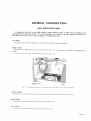
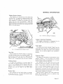
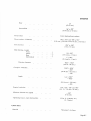
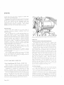
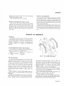
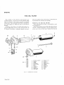
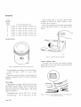
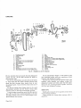
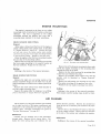
CAR IDENTIFICATION
It is imperative
that the Car and Engine numbers, together with any prefix or suffix letters, are quoted in
any
correspondence cottcerning this vehicle. If the unit in question is the Gearbox the Gearbox
number andãny prefix oi
suffix letters must also be quoted. This also applies when orde¡ing spare parts.
Car Number
.
.
Stamped on the right-hand frame/cross member above hydraulic damper mounting.
Engine Number
Stamped on the right-hand side of the cylinder block abo*e the oil filter and at the front of the
cylinder head
casting.
18
or
19
./ollowing the engine number denotes rhe contpression ratio.
\
Fig'
I
t'ßãl
I
The identifcation numbers are also stanped on a plate situated ín the engine compartment
Gearbox Number
Stamped on a shoulder at the lefrhand rۉr cofrrer of the gearbox casing and on the top
cover.
Body Number
stamped on a plate attached to the right-hand side of the scuttle,
Key Numbers .
.
The keys provided operate the ignition switch and door locks.
Page 4.3
GENERAL INFORMATION
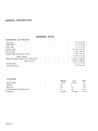
GENERAL DATA
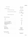
DIMENSIONS ÄND WEIGHTS
Track, Front
.
(2',14 m.)
4'2.
(1.27 m.)
4' 2' (1.27 m.)
Track, Rear
Overall length.
Overall width
8'0"
.
Overall height (Fixed head coupé) ..
Weight (dry) approximate (Fixed head coupé)
(Open 2-seater)
14'
7t'(4'45
m.)
5' 5+" (l'66 m.)
4' 0à' (1 '22 m.)
3' 70+' (l'18 m.)
22! cwts. (l123 kg.)
22 cwts. (1098 kg.)
37' 0" (11'27 m,)
51" (140 mm.)
Cooling system (including heater) . .
Petrol tank
Page
4.4
GENERAL INFORMATION
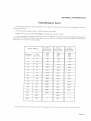
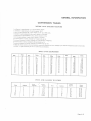
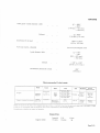
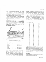
PERFORMANCE DATA
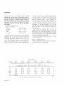
The following table gives the relationship between engine ¡evolutions per minute and road
speed in miles and
kilometres per hour.
The safe maximum engine speed is 5,500 revolutions per mtnute.
Engines must not, under
Any circumstances be allowed to
exceed this figure.
It is recommended that engine revoltttions in excess of 5,000 per minute should not be exceeded for long periods.
Therefore, if travelling at sustained high speed on motorways, the accelerator should be
released occasionally to
allow the car to overrun for a few seconds.
ROAD SPEED
ENGINE
REVOLUTIONS
ENGINE
REVOLUTIONS
ENCINE
REVOLUTIONS
PER N4INUTE
PER MINUTE
PER MINUTE
Top
Top
Gear
Top
Gear
Gear
Kilometres
per hour
Miles
per hour
t6
r0
32
20
48
30
I
64
40
1745
6t4
1862
80
50
2182
2008
2319
96
60
26t8
2398
217 5
|2
70
3054
2780
3221
128
80
3490
3l 56
3667
t44
90
*3800
3521
4lr0
160
r00
*4200
3877
4542
76
il0
x4600
4221
4963
192
120
*5000
4562
5416
208
I30
*5410
4881
225
t40
5200
240
50
5506
:l
:l
3.54:l
436
405
466
873
8r0
932
3.31
309
3.07
l2t
+The fìgures marked thLls
make allowance lor chan_qes in tyre raclius
5
clr-re
I
398
to the eflèct olcentrilLrgal
fot.ce.
Page
4.5
GENERAL INFORMATION
OPERATI
NG I NSTRUCTIONS
e@@:
e
o
C
e
J
ÈF
¡..,1
20
Fig.
2.
4.6
23
24
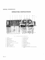
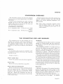
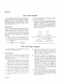
lnstrunrcnts and Controls-Right-hand drive
l. Ammeter.
2. Fuel contents gauge.
3, Light¡ng switch.
4. Oil pressure gauge,
5. Wate¡ temperature gauge.
6. Mixtule control and warning light.
7, Revolution counter.
8. Flashing direction indicator warning lighrs.
9. Speedometer.
10. Brake fluid warning light.
I t. Headlamp dipper switch.
12. Heater-Air Control.
13. Heater Temperature control,
Page
22
14. lnterior light switch
l5 Panel light switch.
16. Heater fan switch.
17. lgnition su,itch.
18. Cigar lighter.
19. Starter srvitch
20. Map )ight switch.
2l Windscreen wiper swirch.
22. Windscreen washer switch
23. Clock adjuster
24. Horn button.
25. Speedometer trip control
26. Flashing direction indicator and headlamp
switch.
flashing
GENERAL INFORMATION
21 22 23 24
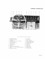
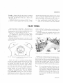
Fig 3, Instruntents ond Conlrols-Left-hand
1. Headlamp dipper switch.
2. Brake ffuid warning light.
3. Speedometer.
4. Flashing directÌon indicator warning lights.
5. Revolution counter.
6. Water temperature gauge.
1. Oil pressure gauge.
8. Lighting switch.
9. Fuel contents gauge,
10. Ammeter.
11. Mixture control and warning light.
12. Flashing direction indicator and headlamp flashing
s"vitch.
13.
Speedometer trip control.
drit,e
14. Horn button.
15. Clock adjuster.
16. Heater-air control.
17. Heater-temperature control
18, Windscreen washer switch.
19. Windscreen wiper switch,
20. Map light switch.
21. Starter switch.
22. Cigar tighter.
23, Ignition swirch.
24. Heater fan switch.
25 Panel light switch.
26. Interior Iight switch
Page ,A..7
GENERAL INFORMATION
INSTRU
Records the flow of current into or out of the
battery. Since compensated voltage control is incorporated, the flow of current is adjusted to the state
of charge of the battery; thus when the battery is
fully charged the dynamo provides only a
small
output and little charge is registered on the ammeter,
whereas when the battery is low a continuous high
charge is shown.
Oil Pressu¡e Gauge
The electrically operated pressure gauge
records
the oil pressure being delivered by the oil pump to the
engine; it does not record the quantity of oil in the
sump. The minimum pressure at 3000 r.p'm. when
hot should not be
less than
40 lbs. per
square
nch.
Note: After switching on, a period of approximately
20 seconds
ENTS
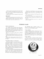
Speedometer
Ammeter
ì
M
will
elapse before the correct reading
is obtained.
Vl/ater Temperature Gauge
The electrically operated water temperature gauge
records the temperature of the coolant by means of a
bulb screwed into the inlet manifold water jacket.
Records the vehicle speed
in miles per hour, total
mileage and trip mileage (kilometres on certain
export models). The trip figures can be set to zero
by
pushing the winder upwards
and
rotating
clockwise.
Headìamp \{arning Light
A red warning light marked "Headlamps" situated
in the speedometer, lights up when the headlamps are
in full beam position and is automatically extinguished
when the lamps are in the dipped beam position.
Ignition Warning Light
A red rvarning light (marked "Ignition") situated
in the speedometer lights up when the ignition is
switched "on" and the engine is not running, or when
the engine is running at a speed insufficient to charge
the battery. The latter condition is not harmful, but
always switch "off" when the engine is not running.
Fuel Level Gauge
Fuel Level Warning Light
An amber warning light (marked "Fuel") situated
in the speedometer lights up intermittently when the
fuel level in the tank becomes low. When the fuel is
almost exhausted the warning light operates con-
Records the quantity of fuel in the supply tank'
Readings will only be obtained when the ignition is
switched "on". An amber warning light situated in
tinuously.
Flashing Indicator Warning Lights
speedometer lights up intermittently when the
petrol level in the tank becomes low. When the petrol
is almost exhausted the warning lìght operates continuously.
Note: Atter switching on, a period of approximately
20 seconds will elapse before the correct reading
is obtained.
The warning lights are in the form of green arrows
located on the facia panel situated behind the steering
tlie
Electric Clock
The clock is built in the revolution counter instrument and is powered by the battery. The clock hands
may be adjusted by pushing up the winder and rotating.
Starting is accomplished in the same manner.
Revolution Counter
Records the speed of the engine
minute.
Page A.8
in revolutions
per
wheel.
'When
the flasher indicators are in operation otle of
the arrows lights up on the side selected.
Mixture Control Warning Light
A red warning light situated above the mixture
control on the facia panel behind the steeriug wheel
serves to indìcate if the mixture is in operation. This
warning light is illuminated immediately control lever
is moved from "off" position.
To change the bulb, accessible behind the facia
panel, pull bulb holder away from "clip in" attachment,
and unscrew bulb by turning anti-clockwise. For full
instructions on the use of the mixture control see
"starting and Driving," page Al6.
GENERAL INFORMATION
Brake Fluid Level and Handbrake Warning Light
A
warning light (marked ,,B¡ake Fluid-Hand-
brake") situated on the facia behind the steering wheel,
serves to indicate if the level in either of the two b¡ake
fluid reservoirs has become low, provided the ignition
is "on". As the warning light is also illuminated
when the handbrake is applied, the handbrake must
be fully reJeased before it is assumed that fluid level
Gear Iæver
Centrally situated and with the gear positions
indicated on the control knob. To engage reverse
gear first press the gear lever against the spring
pressure before pushing the lever forward. Always
engage neutral and release the clutch when the car is
at rest.
is low. If \ryith the ignition ,.on', and the handbrake
fully released the warning light is illuminated the brake
fluid must be "topped up" and the reason for the loss
investigated and corrected immediately. IT IS
ESSENTIAL that the correct specification of brake
flujd be used when topping up.
As the warning tight is illuminated when the hand_
brake is applied and the ignition is ,,on" a two_fold
purpose is served. Firstly, to avoid the possibility of
driving away with the handbrake applied. Secondly,
as a check that the warning light bulb has not ..blown";
if on first starting up the car with the handbrake
fully applied, the warning light does not become
illuminated the bulb should be changed. immediately.
2
CONTROLS ÄND ÄCCESSORIES
Fig.
Accelerator Pedal
4.
The gear positions
Controls the speed of the engine.
Brake Pedal
Operates the vacuum servo assjsted disc brakes on
all four wheels.
Clutch Pedal
Connects and disconnects
the engine and
the
transrnjssion. Never drive with the foot resting on the
pedal and do not keep the pedal depressed for long
periods in traffic. Never coast the car with a gear
Handbrake Lever
Positioned centrally between seats. The handbrake
operates mechanically on the rear wheels only and is
provided for parking, driving away on a hill and when
at a standstill in traffic, To apply the brake, pull the
lever upward and the trigger will automatically
engage with the ratchet. The handbrake is released
by pressing in the knob, and pushing the lever
engaged and clutch depressed.
downward.
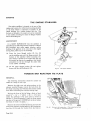
Headlamp Dipper
Seat Ädjustment
Situated on the facia panel behind the steering wheel.
The switch is of the "flick-over" type, and if the head_
lamps are on main beam, moving the lever will switch
the dipped beam on, and main beam
off.
remain so until the switch lever is reversed.
They will
Both front seats are adjustable for reach. Push
the lock bar, situated beside the inside ruuner,
towards the inside of the car and slide into the
required position. Release the lock bar and slide
until the mechanism engages with a click.
Page
4.9
GENERAL IN FORMATION
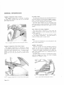
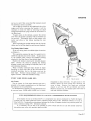
Rotate the knurled ring at the base of the steering
wheel hub in an anti-clockwise direction when the
steering wheel may be slid into the desired position'
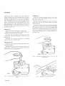
KEYLESS LOCKING is obtainable by first pushing
the interior door handle fully forward and allowing it
to return to its original position. If the door is now
closed from the outside with the push button of the
Turn the knurled ring clockwise to lock the steering
handle fully depressed the door
Steering Wheel Ädjustment
wheel.
will become locked.
Warning.-If the doors are to be locked by this
method the ignition key should be removed
beforehand (or the spare key kept on the driver's
person) as the only means of unlocking the doors
is with this key.
Horn
Depress the circular button in the centre of the
steering wheel to operate the horns.
Note.-The horns will not operate if ignition is off.
Ignition Switch
Inserting the key provided in the switch and turning
clockwise will switch on the ignition.
Never leave the ignition on when the engine has
stopped, a reminder of such circumstances is provided
by the ignition warning light situated in the speedo'
meter.
Fig.
5.
Steering x'heel acliustntenr
Interior Light Switch
Lift the switch lever (marked "Interior") to illu-
Door Locks
The doors may be opened from the outside by
pressing the button incorporated in the door handle,
The doors are opened from the inside by pulling the
interior handles rearward.
minate the car interior.
Both doors can be locked from the inside by pushing
the interior handles forward and allowing them to
return to their original position; this feature only
applies if the doors are fully closed before operating
rhe interior handles, Both doors can be locked from
the outside by means of the ignition key; the locks are
incorporated in the push buttons of the door handles.
To lock the right-hand door insert the key in the
lock, rotate anti-clockwise as far as possible anC
allow the lock to return to its original position-the
door is now locked. To unlock the right-hand door
turn key clockwise as far as possible and allow the
second location head, side and tail.
lock to return to its original position.
To lock the left-hand door rotate key clockwise;
to unlock, rotate key anti-clockwise.
Page
A,l0
Lighting Switch
From "Off" can be rotated into two positions,
giving in the first location side and tail, and in the
Panel Light Switch
Lift the switch lever (marked "Panel") to enable
the instruments to be read at night and to provide
jllumination of the switch markings. The switch has
two positions "Dim" and "Bright" to suit the driver's
requirements. The panel lights will only operate
when the side lights are switched on.
Starter Switch
Press the button (marked "Starter") with the
ignition switched on, to start the engine' Release the
switch immediately the engine fires and never operate
the starter when the engine is running'
GENERAL INFORMATION
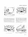
Flashing Direction Indicator
The "flashers" are operated by a lever behind the
steering wheel. To operate the flashing direction indi-
cators on the right-hand side of the car, move the
lever clockwise; to operate the left-hand side indicators, move the lever anti-clockwise. White the
flashiag indicators are in operation, one ofthe warning
lights on the facia panel behind the steering wheel will
llash on the side selected.
Fig.
7. Method of "flashing"
the headlamps
Luggage Compartment Illumination
The luggage compartment is illuminated by the
interior light when this lamp is switched on.
Cigar Lighter
Fig.6.
To operate, press holder (marked "Cigar,') into the
socket and remove the hand. On reaching the required
The flashing dìrection indicator control
temperature, the holder will return to the extended
position. Do not hold the lighter in the ,,pressed-in,,
Map Light
position.
Lift the switch lever (marked ,,Map") to illuminate
the lamp situated above the instrument panel. To
provide ease of entry into the car at night the map
light is switched on when either one of the doors is
openerl, and is extinguished when the door is closed.
Windscreen Wipers
Headlamp Flasher
To "flash" the headlamps as a warning s.ignal, lift
and release the flashing indicator lever in quick succession. The headlamps can be ',flashed" when the
lights are "off" or when they are in the dipped beam
position; they will not "flash" in the main beam
position.
Braking Lights
Twin combined tail and brakc lights are situated
at the rear of the car. The latter automatically light
up when the footbrake is applied.
The wipers are controlled by a three position switch
(marked
"Wiper"). Lift the switch to the
second
position (Slow) which is recommended for all normal
adverse weather conditions and snow.
For conditions of very heavy rain and for fast
driving in rain lift the switch ro the third position
(Fast). This position should not be used in heavy
snow or with a drying windscreen, that is, when the
load on motor is in excess of normal ; the motor
incorporates a protective cut-out switch which unde¡
conditions of excessive load cuts off the current supply
until normal conditions are restored.
When the switch is placed in the "Off" position the
wipers will automatically leturn to a position along
the lower edge of the screen.
Page
A.l I
GENERAL INFORMATION
lYindscreen Washer
The windscreen washer is electrically operated and
comprises a glass water container mounted in the
engine compartment, which is connected to jets at the
base of the windscreen. Water is delivered to the jets
by an electrically driven pump incorporated in the
water container.
Operation
The windscreen washer should be used in conjunction with the windscreen wipers to remove foreign
matter that settles on the windscreen.
Lift the switch lever (marked "V/asher") and release
immediately, when the washer should operate at once
and continue to function for approximately seven
seconds. Allow a lapse of time before operating the
switch a second time.
For full instructions on the use of the Windscreen
Washing Equipment see Section "O".
Heating and Ventilating Equipment
The car heating and ventilating equipment consists
of a heating element and an electrically driven fan
mounted on the engine side of the bulkhead. Air
from the heater unit is conducted:
Fig.
8.
Sleering colutnn adiusttttcnt Jòr rnke
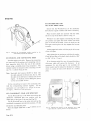
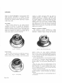
Bon¡et Lock
@arly Cars)
The bonnet is locked by means of the two locks
situated at the sides ol tlie bonnet.
(a) To a built in duct fitted with two doors
(b)
situated behind the instrument panel.
To vents at the bottom of the windscreen to
provide demisting and defrosting.
The amount of fresh air car' be controlled at the will
ofdriver and is introduced into the systemby ciperating
the
"Air"
control lever and switching on the fan.
For full instruction on the use of the Heating and
Ventilating Equipment see Section "O",
Steering Column-Adjustment for Rake
The steering column can be adjusted for rake' To
adjust, release nu! and bolt at the top of the column
located behind the instrunent panel, and adjust to
suit requirements. Re-tighten nut fully after adjustment.
Page 4..12
\\\'
Fs4
Fig.
9.
Unlccking the bonrcl (eu
ll
cars)
GENERAL INFORMATION
To open the bonnet insert the ,,T,, handle key
provided in the lock and on the right-hand side turn
key clockwise, and on the left-hand side turn key
anti-clockwise.
This rvill release the bonnet which will now be
retained by the safety catch. Insert the fingers under
the rear edge of the bonnet and press in the safety
catch.
To close the bonnet push down to the safety catch
position. Hold the bonnet depressed and insert the
"T" handle in the lock. On the right-hand side turn
the key anti-clockwjse and on the left-hand side turn
the key clockwise.
(Later Cars)
Fig. 11. Releasing the bonnet
The bonnet is locked by means of two locks situated
at the sides of the bonnet. To open the bonnet, turn
the two small levers located on the right and left_hand
door hinge posts anti-clockwise and pull to full extent.
This will
release
the bonnet, which will
nov¿ be re_
tained by the safety catch.
Insert the fingers under the rear edge of the bonnet
and press in the safety catch.
To close the bonnet, push down to the safety catch
position, push in the two levers and turn clockwise.
sa"fety catch
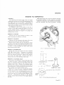
Radiator Fan
The radiator fan is electrically driven, the cutting in
speed being controlled automatically by means
of
a
thermostatic switch incorporated in the engine ccoling
system. The fan will not operate with the ignition
switched off.
When ihe coolant reaches a temperature of approximately 80"C., the thermostatic switch closes and starts
the fan motor. The fan motor will continue to run
until the temperature has fallen below approximately
72"C.
For full information on the Radiator Fan
see
"Cooling System (Section D)".
Interior Driving
Mrror
(Open 2-seater)
This is of the dipping type. Move lever, situated
under mirror, forward for night driving, to avoid
being dazzled by the lights of a following car.
Interior Driving Mi¡ror (Fixed Head Coupe)
This is of the dipping type. Move lever, situated
under the mirror, to the left for night driving, to avoid
being dazzled by the lìghts of a following car.
Fuel Tank Filler
The fuel tank filler is situated in a recess in the
is provided with a hingcd
left-hand rear wing and
Fig 10. Unlocking
the bonnet (la¡er cars)
cover.
Page 4.13
GENERAL INFORMATION
Luggage Compartment (Open 2-seater)
The tuggage compartment is unlocked by pulling
the black knob situated inside the car on seat back
panel right-hand side.
Seat Back Panel
The back panel behind the seat normally serves as a
partition between the driving and luggage compartment. The panel can be lowered to give an increased
boot floor area if required for extra storage'
To lower panel, release the two side fixing bolts
and lower panel to check strap
to
limits. Return
vertical position when extra boot space is
panel
not re-
quired.
Spare Wheet and Jacking Equipment
The spare wheel is housed in a well under the
luggage compartment, and is accessible after removal
of the square lid.
The copper hammer and jack are retained in clips
in the luggage compartment.
The jack handle
is
retained in clips under the spare wheel.
Tools
The tools are contained in a tool roll placed in the
Fig. 12. Luggage comparltrlenl lock conttol (Open 2'seater)
Luggage Compartment (Fixed Head Coupe)
The luggage compartment is unlocked by lifting
the recessed chromium plated lever situated in body
trim panel beside right-hand seat. To operate, insert
finger in recess and lift out lever to full extent.
Retain the lid in the open position by means of the
prop.
spare wheel compartment.
\ryHEEL CHANGING
Whenever possible the wheel changing should be
carried out with the car standing on level ground,
and in all cases with the handbrake fully applied.
Unlock the luggage compartment by pulling the
black knob situated inside car at right-hand side of
seat back panel.
The spare wheel is housed in a compartment utrder-
neath the luggage boot floor; the wheel changing
equipment is retained
Fig. 13. Luggage companmenl lock conlrol (Fixed Head Coupe)
Page 4.14
Fig.
)4.
in
clips.
Spare llheel Housing (Open 2'searer)
GENERAL INFORMATION
't/-u'oo
- 'l,ve
le)sì
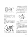
Fig. 17, Hub cap-lefr hand side
Fig. 15. Spare wheel housing (Fixed Head Coupe)
Remove the copper and hide mallet from the tool
kit. Using the mallet, slacken but do not remove the
hub caps; the hub caps are marked Right (off) side
or Left (near) side, and the direction of rotation to
remove, that is, clockwise for the right-hand side and
anti-clockwise for the left-hand side.
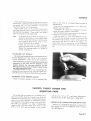
The jacking sockets will be found centrally located
on either side ofthe car. placejack under car with pad
located
clear
in the socket and raise car until
wheels are
of ground. Remove hub cap and withdraw
wheel. Mount the spare wheel on the
splined. hub.
Refit the hub cap and tighten as much as possible by
rotating cap in the required direction, that is, anticlockwise for the right-hand side and clockwise for
the left-hand side.
Lower the jack and finally tighten the hub fully
with the copper and hide mallet.
z*Do -:-s
JátrUÀtr
ta,
h.o
lryr b r r\3',
f-t!o-ã
Fig. 16. Hub cap-right-hand side
18.
l:e.
.lhe iqc( in position for
t he pos¡t¡on oJ Íhe lever
raising the teft-hand side of the car.
shown in the inset controls the opèration ol
the jack screw
Page A.15
GENERAL INFORMATION
STARTING
Prior to Starting
Ensure that the coolant level in the radiator and the
oil level in the sump are correct. Check for sufficient
petrol in the tank.
Starting from Cold
A manual mixture control is provided located in
facia panel behind steering wheel. This control has
six positions; the "fully rich" position being at the
top of the slide marked "COLD". Moving the lever
progressivelydownwards weakens the mixture strength.
The two positions from "HOT" give a fast idle con-
drtion; the last position "RUN" being off.
A red warning light is incorporated in the control
u,hich lights up immediately the lever is moved from
"RUN" position.
When starting from cold the rnixture control should
be moved to the fully rich "COLD" position. Srvitch
on the ignition and press the starter button, but do not
touch the accelerator. Release the starter button as
soon as the engine flres-this is important. If for any
reason the engine does not start do not operate the
starter button again until both the engine and the
starter motor have come to rest.
As soon as the engine speed increases slide the control
progressively to the intermediate "HOT" position.
Drive off at a moderate speed progressively sliding
the mixture control to the "RUN" position until the
knob js at the bottom of the slide and the red warning
light is extinguished.
Always return the control to "RUN" positìon as
soon as possible. IJnnecessary use of the mixture
control will result in reduced engine life.
Starting in Moderate Temperature
In warm weather or if the engine is not absolutely
cold, it is usually possible to start the engine wrth the
mixture control in one of the intermediate "HOT"
positions. Do not touch the accelerator pedal.
Starting When Hot
Do not use the mixture control. If the engine does
not start immediately slightly depress the accelerator
pedal when making the next attempt.
\ilarming Up
Do not operate the engine at a fast speed when first
started but allow time for the engine to warm up and
the oil to circulate. A thermostat is incorporated in
the cooling system to assist rapid warming up. In
very cold weather run the engine at 1,500 r.p.m. with
Page A.16
AND DRIVING
the car stationary until a rise in te[iperature is indicated on the tenrperature gauge.
Driving
(a) Careful adherence to the "Running-in" Instructions given will be amply repaid by obtaining the best
performance and utmost satisfaction from the car.
(b) The habit should be formed of reading the oil
pressure gauge, water temperature gauge and ammeter
occasionally as a check on the correct functioning of
the car. Should an abnormal reading be obtained an
investigatior.r should be made immediately.
(c) Always start from rest in first or second gear;
on a hill always use first gear. To start in a higher gear
will cause excessive clutch slip an d premature wear. Never
drive with a foot resting on the clutch pedal and do
not keep the clutch depressed for long periocls in traffic,
(d) The synchromesh gearbox provides a synchronized change in second, third and top. When
changing gear the movement should be slow and
deliberate.
Wren changing down a smoother gear change will
if the accelerator is left depressed to provide the higher engine speed suitable to the lower
gear. Always fully depress the clutch pedal when
be obtained
changing gear.
(e) Gear changing may be slightly stiff on
a
new
car but this will disappear as the gearbox becomes
"run-in ".
(f) Always apply the footbrake progressively;
ûerce and sudden application is bad for the car and
tyres. The handbrake is for use when parkingthe car,
when driving away on a hill and when at a stanclstill
in traffic.
"Running-in" Instructions
Only if the following important recommendations are
will the high performance and continued good
running of which the Jaguar is capable be obtained.
observed
During the "running-in" period do not allow
the engine to exceed the following speeds and particularly do not allow the engine to labour on hills;
it is preferable to select a lower gear and use a higher
speed rather than allow the engine to labour at low
speed:First 1,000 miles (1,600 km.) .
From 1,000-2,000 miles (1,60t-
2,500 r.p.m.
. . 3,000 r.p.m.
3,200 km.)
Have the engine sump drained and refilled and the
oil filter
to as recommended at the free
is, after the first 500 miles (800 km.).
attended
service, that
GENERAL INFORMATION
SUMMARY OF MAINTENANCE
Daily
Every 5,000 miles (8,000 km.)
Check radiator coolant level.
Carry out 2,500 miles
Check engine oil level.
seryice
Clean carburetter filters.
Clean fuel line filter.
Lubricate door hinges.
WeekIy
Check dynamo belt and adjust
Check tyre pressures.
Check fluid level
der reservoirs.
in brake and clutch master cylin-
if
necessary.
Renew oil filter element.
Exarnine brake friction pads for wear.
Clear drain holes in bottoms of doors.
Monthly
Adjust top timing chain (if required).
Check battery electrol¡e level and connections,
Check front wheel alignment,
Lubricate rear suspension wishbone pivot bearings.
Carry out oil can lubrication of (a) seat runners and
adjusting mechanism, (b) handbrake lever ratchet,
(c) door locks, (d) boot hiuges and lock, (e) bonnet
hinges and catches, (f) windscreen wiper arrns,
(g) accelerator linkage, (h) îuel filler cover hinge,
(i) handbrake cable compensator, fi) brake pedal
Every 2,500 miles (4,000 km.)
Drain engine sump and refill.
Clean oil filter element.
bearing, (k) carburetter linkage.
Check gearbox oil level and top-up
if
Check rear axle oil level and top-up
if
necessary.
Lubricate generator end bush (later cars only).
necessary.
Lubricate steering housing.
Lubricate steering tie-rod ball joints.
Every 10,000 miles (16,000 km.)
Lubricate wheel swivels.
Lubricate propeller shaft universal joints (early cars).
Carry out the 2,500 miles and 5,000 miles service.
Lubricate propeller shaft splines (early cars).
Drain and refill gearbox.
Lubricate carburetter hydraulic piston dampers.
Drain and refill rear
Lubricate rear half shaft universal joints.
Lubricate wheel hub bearings.
Lubricate distributor and check contact poiats.
Clean, adjust and test sparking plugs.
Check clutch free travel and adjust
if
necessary.
axle.
Check and tighten all chassis and body nuts, scl.ews
and bolts.
Renew air cleaner element.
Check handbrake adjustment (early cars only).
Check wheel bearing endfloat and adjust ifnecessary.
Check carburetter slow running.
Renew sparking plugs.
Change over road wheels.
Clean fuel tank filter.
Page A.17
GENERAL INFORMATION
RECOMMENDED LUBRICANTS
Mob
Component
Castrol
Shel
BP
Esso
I
Duckham
Esso Extra
Motor
Esso Extra
Motor
oil 5w/20*t
Mobiloil
Special+
Engine
Upper cylinder lubrication
Gea¡box
.
')
Castrolite+
or
Shell
Super
Rear Axle
I
Ì
Propeller shafts
Rear a-xle half shafts
Havoline
2OW /40
Q5500+
l0w/30f
UCL
Adcoid
Liquid
Regent
or
Viscostatic
or
oil
Castrollo
Shell UCL
or Donax U
UCL
Castrol
x-100
Moror oil
20w/30
Energol
SAE 30
NOL
Esso Gear Oil
Gear Oil
SAE gOEP
Hypoid
Multigear
90
Lubricant
Mobile
upper lube
Esso Extra
Esso
Esso
Mobiloil
A
XL
Mobilube
Castrol
GX9O
Hvpoy
Spirax
90 E.P.
Mobil-
Castrolease
Retinax
30
LM
grease
Front wheel bearings
oil l0w/30rf
Motor
oil 20wl40+t
Q20-50
Castroì XL
-ì.
.
Distrubutor oil can Points
Oil can lubrication
Regent
Caltex/Texaco
G.P.90/r40
UCL
Havoline
30
30
EP 90
Esso Multi-purpose Energrease
L2
Grease H
LB
IO
Esso Multi-purpose Energrease
LB
IO
Marfak
All
purpose
MP
Rear wheel bearings
Distributo¡ cam
Steering housing
Steering tie-rods
Wheel swivels
Mobil-
Castrolease
grease
LM
Retlnax
A
Crease H
L.2
Marfak
Alì purpose
MP
Door hinges
Rear wishbone Pivots
*These oils should not be used in worn engines requiring overhaul. lf an SAE 30 or 40 oil has previously been used in the engine, a slight
in oil consumption may be noiiced but this will be compensated by the advantages gained.
inc¡ease
fAccording to availability in country of operation.
RECOMMENDED HYDRAULIC FLUIDS
Braking System and Clutch Operation
Preferred Fluid
Dunlop Disc Brake
(s.A.E. 70 R3)
Alternative Fluids
Fluid
Recognised brands of brake fluid conforming to
specificat¡on SAE 70 R3, such as Castrol, Girling
Crimson Brake Fluid
Duty Brake Fluid.
Page 4.18
or
Lockheed Super Heavy
GENERAL INFORMATION
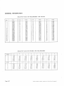
CONVERSION TABLES
METRIC INTO ENGLISH MEÄSURE
I millimetre
is approximately alrr',, and,is exactly .03937,.
centimetre is approximately $,,, and is exactly .3937,,.
I metre is approximately 39f,,, and is exactly 39.37,, or 1.0936 yards.
I kilometre is approxirnately f mile, and is exactly .6213 miles.
I kilogramme is approximately 2i lbs., and is exacrly 2.21 lbs.
f litre is approximately lf, pints, and is exactìy 1.76 pints.
To convert merres to yards- multiply by 70 and divide by 64.
To convert kilomerres to miles, multiply by 5 and divide by g (approx.)
I
To convert litres to pints, multiply by Bg and divide by 50.
To convert grarnmes ro ounces, multiply by 20 and divide by
567.
To find the cubical contents of a motor cylìnder, square the diameter (or
bore), multiply by 0.7g54and multiply the result by the stroke.
I M.P.G.-0 3546 kilometres per litre or 2.g4 litres per kilometre.
MILES INTO KILOMETRES
Kilo.
I
2
Miles
r+
3
l1
4
1l
-5
3l
Kilo.
Miles
l6
17
Miles
KiIo.
Miles
l0
31
l0å
l9+
32
let
46
ao5
LOT
to!
|li
33
20+
21t,
ll+
t8
l9
20
6
Kilo.
2t
34
ILÍ
35
36
37
1
8
4t
22
23
9
5-\
JB
t3
t3å
4+
24
6+
4&
38
39
25
26
s+
40
28
29
30
'7'-
5
l0
ll
6t
T2
4l
6l
1+
8+
8+
l3
t4
l5
6t
et
42
43
44
45
8
o5
ot
47
48
29t
30i
49
50
2r+
'r)
!
5l
23
52
23t
54
55
56
57
58
59
24+
2s+
26t
26+
¿tÉ
al l
JlT
80
4el
90
s5+
62+
3t+
100
200
100
400
s00
600
34+
34+
700
35*
800
900
36
36å
Miles
60
70
3lor
32+
1?¿
33+
53
24+
Kilo.
I000
43+
t24+
r 86*
248'
3
l0+
3'12t
435
4e7t
55e+
621+
PINTS AND GALLONS TO LITRES
Litres I
I
I2
+
Litr.t
51
13.65
l0
88
I1
I
4
+
I
1
r+
al
I
2.27
4+
2
454
9
3
r3+
4
l8
32
Gallont
9.10
l-
aÀ
I
40
48
56
64
72
80
2
3
8
16
Pints
tt4
.11
1
l8
20
96
5
6
7
8
9
l2
Lirres
Approx.
1a ,1<
23
27
27 30
32
31 85
36+
36'40
4l
40.9s
4s+
45 50
50
54+
50.05
54.60
Page 4.21
GENERAL INFORMATION
RELATIVE VALUE OF MILLIMETRES ÄND INCHES
Inches
mm.
0.0394
0.0787
0.t
5
181
0 .l 575
.1968
0
26
21
28
29
30
6
0.2362
3l
7
8
0.2'156
0.3 150
0.3543
o.393'7
32
mjn.
I
2
3
4
9
10
'3780
.4173
36
12
o.4't24
l3
0.5118
37
38
39
o.5512
0.5906
0.6299
t6
l7
18
t9
20
2t
t)
23,
24
25
r
35
40
4t
2'O079
76
52
2.9922
3 .01l5
78
79
80
3.0709
3'1103
55
2.0473
2.0866
2'1260
2.1654
56
2.2047
8t
3
5'l
2'2441
2'2835
2.3228
2'1622
2'4016
2.44tO
2.4803
82
.l 890
3-2284
83
3'2677
84
3'3071
85
3.346s
86
3'3859
8'7
3'4252
3'4646
6l
'4567
62
'4961
5354
.s748
.6142
63
0.7480
o.7874
0.8268
44
.1323
45
46
.8110
0.8661
4'Ì
0.905s
o'9449
48
49
50
.'17 17
.8504
.8898
2.ss91
2.5984
2.6378
"t0
7l
2.',l953
72
2'8t4'1
2'8740
2.9134
2'9528
73
'929t
74
'15
'9685
3.5040
3.5433
3'5827
3.6221
90
9l
92
93
2 6772
2'1166
2'7559
3.1496
88
89
2,5197
64
65
66
67
68
69
.6536
-6929
42
0.9843
5t
58
59
60
386
0.6693
0.7087
43
Inches
54
.2205
.2598
-2992
.3
0 .4331
15
't4t7
34
mm.
5l
.1024
33
11
14
'0236
.0630
.l8l
Inches
mm.
lnches
3.66t4
94
3.7008
95
96
97
98
99
3.7402
3 "?'.?96
.8r
3
89
3.8583
t'8977
3'9370
100
RELATIVE VALUE OF INCHES .A'ND MILLIMETRES
Inches
0
1
)
3
4
5
_L
0
0.0
1.6
3.2
4.8
25'4
2'1 0
28'6
30.2
55.6
52.4
54.0
76'2
'17.8
79'4
8l .0
.6
103.2
104.8
t27'0
128'6
t30.2
106 4
131 8
157.2
50.8
l0l
6
t52'4
154.0
155.6
Inches
+
ló
E
0
I
38 I
2
3
4
5
6
Page A,.22
I
r*
+
ló
.IL
ló
_l
t27
635
889
14J
t39
t65
7
I
143
15 .9
39.7
31 4
66'7
65
1
90.5
I 15.9
141 .3
166 7
92
t17
175
429
1
5
I
t'6
6.4
3t'7
57
'l
7.9
9.5
1l.t
13.3
34.9
60.3
36.5
857
87.3
58.7
82.5
108.0
133.4
84. l
109.5
134.9
160.3
,t
IL
tó
158 .8
l9 .t
44.4
20.6
460
68.3
93.1
69 .8
7t'4
95.2
19'l
t20.7
96.8
t22.2
146.1
147 6
I71.5
r73.0
142.9
t44.5
t68.3
t69
9
1
i6
å
Printed in England by Buckler & Webb
tll.l
136.5
161.9
6t9
|2.'l.r
138
163 .5
1
IÓ
8
23.8
22.2
47.6
73.0
984
123 8
149.2
174 6
492
746
r
00.0
125 4
I
50'8
176'2
Ltd, Church Slreel, Birmingham
3
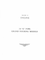
SECTION
B
EI{GINIE
3.8 668" TYPE
GRAND TOTJRIhIG MODELS
INDEX
Removal
Overhaul
Refitting
Cylinder Block:
Overhaul
Cylinder Head:
Removal
Overhaul
Refitting
IND
Decarbonising and Grinding Valves
Engine-Removal and Refitting
Engine-To dismantle
Engine-To
assemble
Engine Mountings
Engine Stabilizer
EX
þontìnued)
Page
8.29
8.19
B.2t
8.23
8.65
8.66
Exhaust Manifolds:
8.43
8.43
Ignition Timing..
B.M
8.45
8.45
8.46
Element replacement
8.47
8.47
Oil Pump:
Removal
Dismantling
Overhaul
Re-assembling
8.48
8.48
8,48
8.50
8.50
INDEX
þontinued)
Pistons and Gudgeon Pins:
Routine Maintenance
Sparking Plugs:
Service procedure
Analysin g service conditio
Standard gap setting
ns
Tappets, Tappet Guides and Adjusting Pads;
Removal of tappets and adjusting pads
Overhaul
8.55
8.5-5
Timing Gear:
Dismantling
8.57
8.57
8.57
8.57
8.58
B.ó6
8.6'l
8.60
8.60
Valve clearance adjustment
B,6t
B,ó I
8.62
8.62
8.63
ENGINE
ENGINE
All "E"
Type models have the twin overhead camshaft
with straight ports and $" lift camshafts.
XK type engine, fitted with the "S', type cylinder
Engine Number
Compression Ratio
Prefix
Colour of
Cylinrler Head
8:1or9:1
R
Gold
head
Compression ratios of 8 to I and 9 to I are specified for the "8" Type engine, the differences in compression
ratio being obtained by varying the crown design of the piston.
The compression ratio of an engine is indicated by 18, 19 following the engine number.
DATA
Camshaft
Number of journals
Four per shaft
Journal diameter
l'00'-.0005,
_.001,
(25.4 mm.-.013 mm.)
-.025
Thrust taken
Number of bearings
Type of bearing
Diameter clearance
Front end
Four per shaft (eight half bearings)
White metal steel backed shell
.0005"
(.013
Permissible end floal
.0045"
(.11
Tightening torque-Bearing cap nuts
to
to
to
'002"
'05 mm.)
to
.008"
'20 mm.)
l5 lbs. ft. (175 lbs. ins.)
(2.0 kg/m.)
Connecting Rod
Length centre to centre
Big end-Bearing type
7/'
(19.68 cm.)
Lead bronze, steel backed shell
Page 8.5
ENGI NE
Bore for big end bearing
2.233', to 2.2335"
(56'72 to 56.73 mm.)
l_.trr"_.006"
(30'16
-.008" mm.)
mm.-'15
-.20
Big end-Diameter clearance
Big end-side clearance
'0015"
(.04 mm.
.0058"
to
to
.0033'
.08 mm.)
to
.0087"
('15 mm. to .22 mm.)
Bore for small end bush
1.00'+.0005'
(25'4 mm._t.013 mm.)
Small end bush-Type
Phosphor bronze-steel backed
Small end-\Vidth
I ðf:'
(27'4 mm.)
Small end bush-Bore diameter
.875',+.0002"
-.0000'mm.)
(22.22 mm.+.005
-.000
Tightening torque-Con rod bolts
ft.
(5'1
37 lbs.
(450 lbs. ins.)
ke.1m.)
Cr¡nkshaft
Number of main bearings
Main bearing-Type
Journal diameter
Seven
Lead bronze, steel backed shell
Front, centre, rear 2'750" to 2.7585"
(69'85 to 69.86 mm.)
Intermediate 2'7495' to 2"750"
(69'84 to 69.85 mm.)
lJt'+.00s"
(42'86 mm.+.13 mm.)
r*"+.0005"
+'001"
(44'45 mm.* '013 mm.)
+.025
ENGINE
Rear
t&'
(47'63 mm.)
Intermediate
,
l+'!'oo2'
.
(30.96 mm.*.05 mm.)
Thrust taken
Centre bearing thrust washers
Thrust washer-Thickness
(2.33
.092'+.001" and .096,+ .001"
mm.{'025 mm. and2.43 mm.+.025 mm.)
End clearance
.004"
(.10
to
to
.006"
'15 mm.)
Main bearing-Length
Front
lå'+'oo5'
Centre
Rear
Intermediate
(38.1 mm.:b.I3 mm.)
1'+,005"
(25'4 mm.I.13 mm,)
Diameter clearance
.4025'-.0042'
('063
Crankpin-Diameter.
.
to
'106 mm.)
2.086',+.0006,
_.000,,
(52.98
mm,f
.015 mm.)
_.000
Length
l+'+'ooo7"
_.0002"
(30.16 mm.*'018 mm.)
_.006
Regrind undersize
'010", '020', .030" and .040"
('25, '51, '76 and 1.02 mm.)
Minimum diameter for regrind
Tightening torque-main bearing bolts
-'040'
(l'02
mm.)
83 lbs.
ft. (1,000 lbs. ins.)
(11
.s kg./m.)
Cylinder Block
Material
"Brivadium" dry liners
ENGINE
Cylinder bores-Nominal
Maximum rebore size
Bore size for fitting liners
Outside diameter of liner
Overall length of liner
Outside diameter of lead-in
Main line bore for main bearings
Valve seat angle--Inlet
.
.
ENGIN
Gudgeon Pin
Type
Fully ffoating
Length
2'840" to 2.845'
(72.14 to 72'26 mm.)
aù
8
(15.87 mm.)
,8750"
to
'8752"
(22.22 ro 22.23 nm.)
Lubricating System
Oil pressure (hot)
40 lbs. per sq. in. at 3,000 r.p.m.
Oil purnp-Type
-Clearance
Eccentric rotor
at end of lobes
.006" maximum
('15 mm,)
-End
clearance
.0025" maximum
(.0ó mm.)
-Clearance
between outer rotor and body
.0l0" maximum
(.25 mm.)
Piston and Piston Rings
Make
Brico
Type
Semi-split skirt
Piston
Skirt clearance
(measured at bottom of skirt
Cudgeon pin bore
at
90o
to gudgeon pitr axis)
'0011'to .0017"
to .043 mm.)
(.028
'8749"
to .8751'
(2.223 to 2.227 mm.)
Compression height
8:lcompressionratio
9:lcompressionratio
2.069' to 2.064"
(52'42 to 52.55 mm.)
2.247', to 2.242"
(56'94 to 57.07 mm,)
Page B,9
E
ENGI N E
Piston rings-Number
Compression
Oil control
I
Piston rings-rWidth
0'777'to '0787'
Compression
(1'97 to 2,00 mm.)
.155"
to
.156"
(3.94 to 3.96 mm.)
Piston rings-Thickness
.124"
fo
'130"
(3'15 to 3'30 mm.)
.119"
ta
'127"
(3'02 to 3'23 mm.)
Piston rings--Side clearance in groove
Compression
.001"
to
'003"
('02 to '07 mm.)
.001'to
Oil Control
'003"
('02 to '07 mm.)
Piston rings-Gap when frtted to cylinder bore
Compression
'015' to '020"
(.38 to '51 mm.)
.011"
Oil control
to .016'
('28 to '41 mm.)
Sparking Plugs
Make
Champion
.
UN12Y+
UNl2Y+
'025',
('64 mm.)
+ N.3 for racing.
Tappets and Tappet Guides
Cast iron (chilled)
-Outside
diameter
1.3738'
T.o
1.3742'
(34'89 to 34'90 mm.)
ENGINE
Diameter clearance
'0008"
to
.0019"
('02 to .048 mm.)
Tappet guide-Material
-Inside
Austenitic iron
diameter (before re.aming)
-Reaming
1
'353' to 1.357"
(34.37 to 34'48 mm.)
size (when fitted to cylinder head)
L.375',+'M07',
(34.925 -'0000'
mm.f .018 mm.)
-.000
-Interference
(shrinþ fit in head
Timíng Chains and Sprockets
Number of pitches-Top chain
-Bottom
Crankshaft sprocket-Teeth
chain
Intermediate sprocket, outer-Teeth
Intermediate sproeket, inner-Teeth
Camshaft sprocket-Teeth
Valve Timing
Inlet valve
Inlet valve
opens
closes
Exhaust valve opens
Exhaust valve closes
15" B.T.D.C.
57'A.B.D.C.
57'B.B.D.C.
l5'A.T.D,C.
(with valve clearances
at .010" (.25 mm.))
Valves and Yalve Springs
Valves-Material, Inlet
Exhaust
set
ENGI NE
Valve head diameter,
Inlet
.
Valve clearance-Inlet
-Exhaust
Valve seat angle-Inlet
-Exhaust
Valve spring-Free length.
Valve Guide and Valve Seat Insert
ENGINE
Valve guicÍe-Inside diameter-Inlet
+'-.0005"
-.0015,,
.(7'94 mm.-'013
mm.)
-'038
Exhaust
mm.)
t'c+'OOOs"
(7'94 mnl.t'Ol mm.)
Interference fit in head
.0005"
(.013
Vaive seat inserts-Material
.0022"
.055 mm.)
to
to
Cast iron (centrifugally cast)
[nside diameter
Inlet
.
lt'+.003'
-'001"
(38'1*.076
mm.)
.
-'025
Exhaust
mm.)
1.379" to 1.383'
(35'03 to 35.13 mm.)
Interference (shrink) fit in head
.003"
('076 mm.)
Recommended Lubricants
I
Mobil
cu.t.ol
Regent
Caltex/Texaco
Engine
Mobiloil
Special*
Castrolite*
or
Cas¡rol XL
Esso
Extra Motor
Esso
Extra Motor
oit 5w/20*t
oit t0w/30*t
Viscostat
Motor
oít 20w /40*l
Mobil
Upperiu
Castrollo
U.C.L
*These oils should not t¡e used in rvom etrgines
requiring
iricrease in
oil consumpiior may
be noticed but this
U.C.L.
Esso
be
will
or
Q55oo*
Esso Extra
Upper cylinder lub:-ication
Q20-50
overhaul. tl an SAE 30 or
Adcoid
Liquid
40 oil has prer,iously been used
be compensated by the advantages gained.
Havoline
20w /40
or
l0w/30{
Regent
U.C.L.
in the engíne, a slight
'lAccording to availabiìit;r in countr¡, of operation.
Capacities
Engine (reflll)
Imperial U.S.
15 pints 18 pints
Litres
8+
Page B,l3
ENGI N E
ROUTINE MAINTENANCE
DÁ.ILY
EVERY 2,500 MrLES (4,000 KM,)
Checking the Engine Oil Level
Changing the Engine Oil
Note: Under certain adverse operating conditions,
conducive to oil dilution and sludge formation,
more frequent oil changing than the normal
Check the oil level with the car standing on level
ground otherwise a false reading will be obtained,
Remove the dipstick and wipe it dry. Replace and
withdraw the dipstick; if the oil level is on the knurled
patch, with the engine hot or cold, no additional oil is
required. If the engine has been run immediately
prior to making an oil level check, wait one minute
after switching off before checking the oil level.
t((tr{tl(((l(((l
Lril((r\((\((lt\(({t((\tt\l(\t(tltl((t((((tt(t{(\t
2,500 mile (4,000 km.) period is advised. Where
the car is used mainly for low-speed city driving,
stop-start driving particularly in cold weather
or in dusty territory the oil should be changed
at ieast every 1,000 miles (1,600 km.).
The draining of the sump should be carried out at
the end of a run when the oil is hot and therefore will
flow more freely. The drain plug is situated at the
right-hand rear corner of the sump. When the engine
oil is changed, the oil fi.lter which is situated ou the
right-hand side
of the
engine, must also receive
attentron.
First drain the oil from the frìter by removing the
small hexagon-headed drain plug situated at the
Fie.
1.
Engine dipstick.
Note: Almost all modern engine oils contain special
additives, and whilst it is permissible to mix
the recomrnended brands
it is undesirable. If
it is desired to change from one brand to anoiher
this should be done when the sump is drained
and the Oil Company's recommendation in
regard to flushing procedure shouid be followed.
Fig.
3.
Engine drain plug
bottom of the frlter head. Unscrew the ce¡rtral bolt
and remove the canister and element. Thoroughly
wash these parts in petrol and allow to dry
out. When
replacing the canister ensure that the circular rubber
seal in the filter head has not become dispiaced.
(Attention is drawn to the importance of renewing the
filter element at 5,000 miles (8,000 km.) intervals).
Note: Almost all modern engine oils contain special
additives, and whilst it is permissible to mix the
recommended brands it is undesirable. If it is
Fig.
Page 8.14
2.
Engine oil filler.
desired
to change from one brand to another
ENGI N E
this should be done when the sump is drained,
and the Oil Company,s recommendation in
regard to flushing procedure should be followed.
Fig.
the
5. Liít.ofl the rc
Apply
t
.¡ctet+,'A'.
clropr of oil around
'B'.'
th
Líghtl¡,
s.rtrcur
Il the gap ls lucorrect, slacken íhe two screws
6.) securing the fixed contact plate and turn the
eccentric-headed acfjustmeut scre\À, (B) in its slot until
tl.re requiled gap is obtained Tighten the securing
(A Fig.
A,
screws and re-check the gap.
Fig.4
Ensittt, oi! filter
sccuring bt'11. g. drain plrrg:-C. oil pressure relief v¡rlve
union
Exantine the colttact breaker points.
are burned
or
If the contacts
blackened. clean them u,ith a fine
carborundum stone or very fine emery cloth. After_
Ðistributor Lubrication
Take care to prevent oil or grease from getting on
or near the contact brcaker points.
Retnove the moulded cap at the top of the distributo¡
by sprìnging back the tu,o ciips. I_ift off the rotor
arm
Ðistributor Contact Breaker points
Check tbe gap between the contact points with
feeler
gauges when the
one of the
cams on the distr
crewdriver
and feeler gauge
The correcr gap .014,-.016, (.36_.41 mm.).
ñ
l\l Ðl I
Checking..the gap between the
Ff:9:
t he two screws'A' secure lhe
fxed con
is adjusted iy
*r"
^iàir'à¡
""rrnt
Þtã¡
ints.
gap
Page B.15
ENGIN
E
wards wipe away any trace of grease or metal dust
with a petrol moistened cloth.
Cieaning of the contacts is made easier if the contact
breaker lever carrying the moving contact is removed.
To do tl.tis, remove the nut, insulating piece and
connections from the post to which the end of the
contact breaker spring is anchored' The contact
breaker lever can now be liited off its pivot post.
Sparking PIugs
Every 2.500 nriles (4,000 km.) or rnore often if
operating conclitions detrand. wilhdraw, cìean alld
reset the plugs.
The only efficient wav to clean sparking plugs is to
have thetn properly serviced on machiues specially
designed
for this pLtrpose.
These lnachines operate
lvith compressed air and trtilise a dry abrasive material
specially graded and selected to remove harmlul
deposits from the plug insLrlator without danraging
the insulator surface. ln addition the rnajority of the
lrrachines iucorporate electrical testing apparatus
enabling the plugs to be pressure tested to check their
eiectrical efficiency and qas tightness.
the points shotrld be
'025'
the
move
gap
always
('64 mrn.). When adiusting the
wire.
side wire-never bend the centre
The gap
between
The Champion Sparking Plug Co. supply a special
combinatiott gauge and setting tool, the use ol which
is recommended.
Every i0.000 miles (16,000 km.) a ne\\' set ol plugs
ol the recommended type should be fitted. To save
pctrol and to ensttre easy starting, the plLrgs should be
cleaned and tested regularly.
Ð1iER.Y -5,000
MILES (8.000 KM.)
trVater Fump/Dynamo tselt Tension-(Early Cars)
When the belt is correctl¡' telisioned ir should be
possible to depress the belt about hallan inch (12 mm.)
midu'ay betr¡'een the w'ater purlp and dynamo pulleys.
Adjustrnent is effected by slackening the three
dynamo mounting bolts. l¡oving the dynanlo until
the correct tension is obtairted and tightening the boìts
Do not overtighten the belt or this ivill cause undue
uear ol the belt and the u'ater pul.np and dYnarno
bearings. Slackness of the belt mav cause slippa-qe
u,ith the possible result of a squealing noise fronr the
belt and a reduced charging rate from the dynamo.
Page B.16
lig.7. Ttt ruliust thc fan bclt lension, sluckett th.e ¡.hre.c dt'ttûtno
ntì,tnting holtí tttrl niot'e ¡he tl)'nanto ro tha leçired prtriliittt.
Later Cars
I)ynamo and Vy'ater Pump Belt ReplacemenÉ
The dynamo and tvater punip belt is kept at the
correct tension by nleans ol a spring ioadeC jockey
pulley on the right hand side of tlie engine. l1-the belt
has to be replaced carry or'tt the folìowing procednre:Slacken the two bolts secLlrlng the civnamo to the
mounting bracket. Removc the nut a¡lci unscrew the
bolt securing the top dynamo link to the dynamo'
Slacken the bolt securing the dynamo link to the
engine and press the dynamo as far as possible iorvards
the engine. Place the new belt in position t.;n th¿
wâter punlp, jockey ancl crankshalt pLrile¡'s and by
pressing thejockey pLrtley torvards the engine ¡lass the
belt over the dynan'ro pLrLley. Pass tlie dynan'rLr
securing top bolt thrcLigh the iink and screw into iire
iug of the dynarno. Fuil the dynamo ailay ircrl tii':
engine as far as possible ano tighten the top ii'nanro
securing bolt and replace tire lock nut. Trgìrten the
bolt securing the clynarnir link to the errgìre arll aiso
tl-re
iwo bottonl dynamo niouniing
c':rlts
ûii Filter Element
It is nlost importani to rene\\' ihe oll filter
elenien:-
everr, i.000 rriles (8,000 krn.) as aitei- this miìeege it
r¡,ill hale become chokeC with irnpurities.
To gtrar'd against the possibility of the filter ce irrg
neglecteC
io ilre
extent ',rhere ihe elenreni becomes
conrpletel¡' chol<ed, a baiance lalve is incorpcrated in
the filter heacl which allov,'s unûite¡ed oil to b¡''-pass the
elenrerrt and reach bearin-es. This will be acccinpanìed
b1'a droo in the irormaì oil pressures of some lC lb'
ENGI NE
per sq. in. and if this occurs the filter element should
be renewed as soon as possible.
The oil filter is situated on the right-hand side of the
engine and before removing the canister it will be
necessary to drain the filter by removing the small
hexagon-headed drain plug situated at the bottom of
the filter head.
To gain access to the element, unscrew the central
bolt when the canister complete with the element can
be removed. Thoroughly wash out the canister with
petrol and allow.to dry before inserting the new
element.
\Vhen replacing the canister ensure that the circular
rubber seal in the filter head has not become displaced.
Top Timing Chain Tension
If the top timing chain is audible adjust the tension
as
follows:This operation requires the use of a special tool to
enable the adjuster plate to be
rotated. To gain access
to the adjuster plate remove the
breather housing
attached to the front face of the cylinder head.
Slacken the locknut securing the serrated adjuster
plate. Tension the chain by pressing the locking
plunger inwards and rotating the adjuster plate in an
anti-clockwise direction.
When correctly tensioned therc should be slight
flexibility on both outer sides of the chain below the
camshaft sprockets, that is, the chain must not be
dead
tight,
Release locking plunger, and securely
tighten locknut. Refit the breather housing.
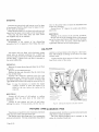
EVERY 10,000 MrLES (16,000 KM.)
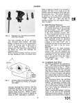
Air Cleaner
The air cleaner is of the paper element type and
Fig.
is
situated in the engìne compartment on the right-hand
side adjacent to the carburetters.
No maintenance is necessary, but the element should
be renewed every 10,000 miles (16,000 km.) or more
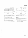
FUEL REQUIREMENTS FOR 9 TO
I
8.
The
air clet:ner.
frequently in dusty territories. To gain access to the
element release the three spring clips retaining top
cover to base. Remove two wing nuts attaching
cleaner to air box and lift out element and cover.
Remove serrated nut, and retainer plate from base of
unit and withdraw element.
and 8 TO 1 COMPRESSION RATIO ENGINES
If the engine of your car is fitted-with 9 to I compression ratio pistons (indicated by 19 af:'rr the engine
number) use only Super grade fuel with a minimum octane rating of 98. (Research method.) If a car is
fitted with 8 to I compression ratio pistons (indicated by /8 after the engine number) use premium grade fuel
with a minimum rating of 91. (Research method),
If, of necessity, the car has to be operated on lower octane fuel do not use full throttle otherwise
detonation may occur with resultant piston trouble.
Page
B.l7
ENGI N E
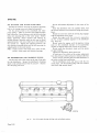
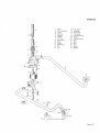
I
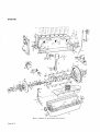
FiS.
Page B.l8
9.
Cross seçtional view of the engine.
ENGI N E
ENGINE REMOVAL
ENGINE REMOVAL
Remove the bonnet (for details see Section N.).
Disconnect the battery.
Drain the cooling system by turning the radiator
drain tap and removing the filler cap. Conserve
il anti-lreeze is in use.
Slacken the clip on the breather pipe, unscrew the
coolant
two win_q nuts and remove the top of the air cleaner.
Disconnect the petrol feed pipe below the centre
carb lrretter.
Slacken the clips securing the water hoses lrom the
cylinder head and radiator to the header tank.
Slacken the clips securing the heater hoses to the
manifold.
Disconnect the brake vacuum pipe.
Disconnect the two electrical connections from the
lan control thermostat in the header tank together
with the anchoring clip.
Remove tl.re ti.vo nuts and bolts securing the header
tank nrounting bràcket to the lront cross member.
Disconnect the radiator header tank overflow pipe
and remove the header tank complete with mounting
bracket.
Disconnect
carb uretter.
Remove
the throttle linkage at the
the green/blue cable lrom the
rear
Remove the four nuts
downpipe to the exhaust
pipes at the silencer assem
Collect the sealing rings
lolds and the downpipes.
Remove the seats, radio (if fitted) and the ash
tray.
Remove the three setscrews securing the propeller
shaft tunnel cover to the body.
Apply the handbrake and remove the gear lever
knob.
Slide the propeller shaft tunnel cover over the hand_
brake and gear levers. Withdraw the tunnel cover.
Turn back the carpet. Withdraw the plastic gearbox bellows having removed the sir drive screws.
Remove trim and screws securing the gearbox cover.
Remove gearbox cover and the gear lever,
Remove the engine rear mounting plate.
Remove the
four bolts and self-locking nuts
joint to
securing the front propeller shaft universal
the gearbox flange.
Remove the torsion ba¡ reaction
tie plate from
beneath the car using either a ramp or pit.
Remove the two cables from the reverse light switch
on the gearbox top cover. When refitting,
water
temperature transmi tter.
Remove the white/black cable from the distributor
to the C.B. coil terminal and the white cable from the
S.W. coit terminal.
Disconnect the battery cable and the solenoid
switch cable from the starter motor.
Remove the bolt from the oil filter canister and
remove the canister, together with the filter, from
below ensuring that the rubber seating ring is
re_
newed when refitting.
Pr€Ínovê the lower crankshaf[ pulley, complete with
the crankshaft damper and drive belt. Remove the
ignition timing pointer from the sump. Mark the
pulley and the damper to facilitate refitting.
Remove the upper clip from the water pump hose.
Remove the white and brown cable from the oil
pressure element.
Remove the revolution counter generator complete
with cables.
Disconnect the brown/yellow cable from the ,.D"
terminal on the dynamo and the brown7green cable
from the "F" terminal.
these
cables can be fitted to either terminal.
Remove the engine earth strap from the left hand
side member.
Disconnect the clutch slave cylinder.
Support the engine by means of lifting tackle,
utilizing the lilting straps (later cars) or the engine
lifting plate (Churchill Tool No. J.g) in the case of
early cars and by inserting the trolley jack und.er the
gearbox from the front of the car.
Remove the self-locking nut and stepped washer
from the engine stabiliser.
Remove the bolts from the front engine mountings.
Remove the speedometer cable.
Raise the engìne on the lifting tackle and, keeping
the engine level, move it towards the front of the car
ensuring that the water pump pulley clears the sub_
frame top cross member and that the bell housing
clears the anchor brackets at the rear of the torsion
bars.
Gradually lifting the front of the engine and
lowering the rear, withdraw the engine irom the
front.
When withdrawing the engine ensure that the rears
Page B.l9
ENGINE
of the camshaft covers do not foul the bonnet drain
channel and that the brake pipe is not damaged.
REFITTING
Refitting the engine is the reverse of the removal
procedure.
Note: Care must be taken to ensure that the brake
pipes are not damaged at the front sub-frame cross
members and that the engine does not foul the torsion
bar anchor brackets or displace the silver steel
locating bars,
Replace the exhaust manifold sealing rings and
if
the cylinder head nuts have been removed they should
be tightened to a torque of 54 lb.ft' (7'4 kgm')' Bleed
the clutch hydraulic system, reset the manual mixture
control and adjust the engine stabiliser.
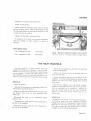
Fis. 10.
Page 8.20
Fis. 11.
The engine
iàiir-iàrt,
Removing the engine
tifiing plate (Churchill Tool No'-J'8')' On
liapt oie ftted ro rhe cvlinder head'
ens¡ni t¡ft¡ns
front above'
ENGI NE
ENGINE TO DISMANTLE
Break the locking wire on the two setscrews securing
GENERÂL
The following instructions apply when the engine
components are removed in the following sequence with
the engine unit out of the chassis. Dismantling of
sub-assemblies and the removal of individual components when the engine is in the chassis frame are dealt
with separately in this section.
All references made in this section to the top or
bottom of the engine assume the engine to be in the
normal upright position. References to the left- or
right-hand side assume the engine to be upright and
looking from the rear.
the camshaft sprockets to their respective camshafts.
Remove the setscrews and withdraw the sprockets
-Having
from the camshafts with chain ir.r position.
REMOVE STÁ.RTER
lJnscrew the two nuts securing the starter to the
clutch housing and withdraw the starter.
R.EMOVE GEÄR.BGX
Unscrew the four setscrews and remove the cover
plate from the front face of the clutch housing.
Remove the set bolts and nuts securing the clutch
housing to the engine and withdraw the gearbox unit.
The gearbox must be supported during this operation
in order to avoid straining the clutch
driven plate
and constant pinion shaft.
Fig.
12.
Adjusting the top timing chain.
R-EMOVE DISTRIBUTOR
Spring back clips and remove the cover complete
with bigh tension leads, Disconnect the electrical
cable from the distributor. Slacken the clamp plate
boit and withdrarv distributor. Remove the setscrew
and remove the clamp plate. Note the cork seal in
recess at the top of the distributor drive hole.
R.EN4CVE CYLIhII}ER HEAD
Ðisconneot the distributor vacuum feed pipe from
the front caibure'rter. Remove the high tension leads
frcm tlie sparking plugs and lead carrier from the
cylinder head studs. F.emove the sparking plugs.
Disconnect the camshaft oii feed pipe from the rear of
the cylirrder head. Remove the eleven dome nuts from
each camshaft co.¡er and lift off the covers.
Remove the fcur dome nuts securing the breather
hcrising and r:'ithdrar,'; housing. Release the iension
on the camshafi chl:.irr by siackening the nut on the
e+r'entriç idle:' sprocket shaft, depressing the springIoarieci stop peg ar-id rotating serrated adjuster plate
elock',¡'ise. Anti-clock+ise rotarion ôf thË serrated
eCjuster viewed from the front of the engine tightens
the chairr,
,-==-È
.- 2¿'--l
ll
zpròs,i,*{
POSITION OF PECS IMPORTANT
CRIND
AWAY
I
Fig.
13.
The top timing chain adjustihg tool.
Page 8.21
ENGIN
E
once disconnected the camshaft sprockets do NOT
rotate the engine or camshafts.
Slacken the fourteen cylinder head dome nuts and
six nuts securing the front of the cylinder head a part
of a turn at a time in the order shown in Fig. 18 until
the nuts become free. Lift off the cylinder head
complete with exhaust manifold and inlet manifolds.
Remove and scrap the cylinder head gasket.
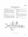
REMOVE CLUTCH ÄND FLYWHEEL
Unscrew the six setscrews securing the flange of the
clutch cover to the ffywheel and remove the clutch
assembly. Note the balance marks 'B' stamped on
the clutch cover and on the edge of the flywheel.
Knock back the tabs of locking plate securing the
ten flywheel
bolts.
Unscrew the flywheel bolts and
remove the locking plate. Remove flywheel lrom the
crankshalt flange by gently tapping with a rawhide
mallet.
REMOVE CRANKSHAFT DÄMPER
Unscrew the large nut and remove the plain washer.
Insert two levers behind the damper and ease it off
the split cone-a sharp tap on the end of the cone
will assist removal.
REMOVE WATER PUMP
Unscrew the set bolts and three nuts, and remove
the water [ju mp from the timing cover. Note the gasket
between the pump and timing cover.
Remove the nut and bolt securing the oil pump
inlet pipe clip in the b¡acket on the oil pump.
Withdraw the pipe from the PumP.
Tap back the tab washers and unscrew the three
bolts se,;uring the oil pump to the front main bearing
cap. The oil pump can now be withdrawn.
Remove the coupling shaft from the squared end of
the distributor and oil pump drive shaft.
REMOVE PISTONS .A,ND CONNECTING RODS
As the pistons will not pass the crankshaft it will
be necessary to withd¡aw the pistons and connecting
rods from the top.
Remove the split pins from the connecting rod bolt
nuts and unscrew nuts. Remove the connecting rod
cap, noting that the corresponding cylinder numbers
on the connecting rod and cap are together.
Withdraw the piston and connecting rod from top
of cylinder block.
Note: Split skirt pistons'MUST be fitted with the
split opposite to the thrust side, that is, with
the split on the left-hand or exhaust side of
the engine. To facilitate correct fitting the
pistons crowns are marked "Front".
REMOVE TIMING COVER
Remove the set bolts securing the timing cover to
the front face of the cylinder block. Remove the timing
ccver, noting that the cover is located to the cylinder
block by two dowels.
REMOYE OIL FILTER
Detach the short length of flexible pipe between the
oil filter head and the oil sump.
Unscrew the four set bolts securing the oil filter
head to the cylinder bloòk and remove filter head,
REMOVE SUMP
r)rain the sump by removing the hexagon plug and
washer from the right-hand side of the sump.
Remove the twenty-six setscrews securing the sump
to the crankcase and the four nuts securing the sump
to the timing cover. The sump can now be removed.
REMOVE OIL PUMP AND PIPES
Tap back the tab washers and unscrew the two set
bolts securing the oil feed pipe from the oil pump to
the bottom face of the crankcase. Withdraw the pipe
from the pump.
Remove the nut and bolt securing the oil pump
inlet pipe clip to the bracket on the main bearing cap.
Page 8.22
REMOVE TIMING GEAR ASSEMBLY
When removing the bottom timing chain tensioner
from the engìne, remove the hexagon head plug arrd
tab washe¡ from the end of the body. Insert an Allen
key into the hole until it registers in the end of the
restraint cylinder. Turn the Allen key clockrvise until
the restraint cylinder can be felt to be fully retracted
within the body. The ad.iuster head will then be free
of the chain.
Knock back the tab washers on the two set bolts.
securing the chain tensioner to the cylinder block.
Withdraw the bolts and remove the tensioner
together with the conical gauze frlter fitted iil the
tensioner oil feed hole in the cylinder block this
should be cleaned in petrol.
Unscrew the four set bolts securing the front
mounting bracket to the cylinder block. Release the
tabs of the tab washers and ¡emove the two screwdriver slotted setscrews from the rear mounting
ENGINE
bracket; these setscrews also secure the intermediate
timing chain damper bracket.
The timing gear can now be removed.
REMOVE CRÄNKSITAFT
Knock back the tab washers securing the fourteen
main bearing cap bolts, Unscrew the bolts and remove
the main bearing caps, noting the corresponding num-
REMOVE DISTRIBUTOR DRIVE GEAR
Tap back the tab washer securing the distributor
drive gear nut and remove the nut and washer. Tap
the squared end of the distributor drive shaft through
the gear, noting that the gear is keyed to the shaft.
Remove the gear and thrust washer and withdraw the
drive shaft.
bers stamped on the caps and bottom face ofcrankcase
and also the thrust washers fitted to the recesses in the
centre mai¡ bearing caps.
Detach the bottom halfofthe oil return thread cover
from the top half by unscrewing the two Allen screws.
Note that the two halves are located by hollow dowels.
The crankshaft can now be lifted out from the crankcase.
ENGIN
E-TO
ASSEMBLE
GE¡IERÄL
All references in this section to the top or bottom
of the engine assume the engine to be upright, irrespective of the position of the unit when the reference
is made. References to the left- or right-hand side
assume the engine to be upright and looking from
the rear.
F'IT DISTRIBUTOR DRIVE SHAFT BUSH
If a new bush is to be fitted, press the bush i¡to the
bore of the lug at front of cylinder block.
Ream the bush in position to a diameter of
*"]:ffi;;"(,e
o5
mm
l3f?ïil
Fig.
FIT CRANKSHAFT
Fit the n.rain bearing shells to the top half of the
main line bore in the cylinder block. Lay the crankshaft in the bearing shells. Fit the bottom half of the
oil return thread cover to the top half which is bolted
to the cylinder block behind the rear main bearing.
The two halves are located by hollow dowels and
secured with Allen screws. The clearance between the
oil return thread cover and the oil return thread on
the crankshaft should be .0025" to .0055,, (.06 to .14
mm.).
The two halves of the oil return th¡ead cover are
supplied only as an assembly together with the dowels
and scrervs.
Fit the centre main bearing cap with a thrust washer,
white metal side outward, to the recess in each side
of cap. Tighten down the cap and check the crank-
14.
The crønkshaft thrusf washers.
shaft end float, which should be .004' to .006,, (.10
to '15 mm,). The thrust washers are supplied in two
thiclç¡"s"r, standard and .004" ('10 mm.) oversize and
should be selected to bring the end float witåi¡
permissible limits. The oversize thruqt washers are
stamped +.004'(.10 mm.) on the steel face.
Fit the main bearing caps with the numbers stamped
on the caps with the corresponding numbers stamped
on the bottom face of the crankcase.
Fit the main bearing cap bolts and tab washers and
righten to a torque of 83 lb.ft. (11.5 kgm.).
Test the crankshaft for free rotation.
The tab washers for the rear main bearing bolts are
longer than the remainder and the plain ends should
be tapped down around the bolt hole bosses.
Page 8.23
ENGINE
FIT DTSTRIBUTOR ÄND
OIL PUMP DRIVE GEAR
Ensure that the Woodruff key on the distributor
drive shaft is in good condition and renew if trecessary.
Place the drive shaft into position with the offset
slot in the top of the shaft as shown in Fig. 16.
Withdraw the shaft slightly maintaining the same
slot position and place the thrust washer and drive
gear on the end of the shaft. Press the shaft itlto the
drive gear ensuring that the key engages thc keyway
co
rrectly.
Fit the
narke¿l on the
Fip.
- 15. Showing rhe corresponding numbers
màin bearing cap and the crankcase'
pegged tab washer with the peg in the keyway
of the drive gear.
Fully tighten thc nut and secure with the tab washer.
Check the end float of the shaft which should be '004"
to '006'('10 to '15 nrm.).
FIT PISTONS AND CONNECTING RODS
Turn the engine on its side. Renrove the connecting
rod caps and ût the pistons and cotlnecting rods to
their respective bores from the top of the cylinder
block, using a suitable piston ring compressor' The
cylinder number is stamped on the corlnecting rod and
cap, No. I cylinder beirtg at rear.
If
no clearance exists fit a new oil pump/distributor
drive gear which will restore the clearance. In an
emergency if a new drive gear is not available, the
thrust washer may be reduced in thickness by rubbing
down on a piece of emery cloth placed on a surface
plate.
Note: Semi-split skirt pistons MUST be fitted rvith
the split opposite the thrust side, that is, with
the split on the left-harrd or exhaust side of the
engine. To facilitate correct fitting the piston
crowns are marked "Front".
Fit the connecting rod caps to the connecting rods
with the corresponding numbers together' Fit the
castellated nuls and tighten to a torque of 37 lb'tl'
(5'l kgm.). Secure nLrt with split pìns'
FIT CRANKSHÄFT GEAR ÄND SPROCKET
Fit the Wooclruff key to the inner slot and tap
distributor crankshaft gear into position with
the
the
widest part of the boss to the rear (see Fig. 25)'
Fit the Woodruff key to the outer slot and tap the
crankshaft timing gear sprocket into position' Fit the
oil thrower and distance Piece.
Turn the engine until Nos. I and 6 pistons are on
T.D.C.
Page 8.24
Fis.
"
16. Showinl the position of the distribtnor drive shaft
ofset when Ño.6 (.ft'ont) piston is on Top Dead Centre.
ENGINE
FIT OIL PUMP AND PIPES
Fit the coupling shaft between the
TIMING CHAIN TENSIONER
squared end of
the distributor drive shaft and the driving gear of the
oil pump. Secure the oil pump to the front main
bearing cap by the three dowel bolts and tab washers.
Check that there is appreciable end-float of the short
Fit the oil delivery pipe from the
oil pump to the bottom face of the crankcase u,ith a
new 'O' ring and gasket. Fit the suction pipe with
a new 'O' ring at the oil pump end.
coupling shaft.
TO ASSEMBLE TIMING GEAR
Fit the eccentric shaft to the hole in front mounring
bracket. Insert the spring and locking plunger for the
serrated plate to the hole in the front mounting
bracket. Fit the serrated plate and secure with the
shakeproof washer and nut. Fit the idler sprocket
(21 teeth) to the eccentric shaft.
Fit the two intermediate sprockets (20 and 28 teeth)
to their shaft with the larger sprocket forward and press
the shaft through lower central hole in rear mounting
bracket.
Secure
with the circlip at the rear of
the
bracket.
Fit the top timing chain (longer chain) to the sma[
internrediate sprocket and the bottom timing chain
(shorter chain) to the large intermediate sprocket.
Loop upper timing chain under the idler sprocket
and offer up the front mounting bracket to the rear
mounting bracket with the two chain dampers interposed between the brackets.
Fit the intermediate damper to the bottom of the
rear mounting bracket with two screwdriver slotted
Place the timing chain tensioner, backing plate and
filter in position so that the spigot on the tensioner
aligns with the hole in the cylinder block. Fit shims,
as necessary, between the backing plate and cylinder
block so that the tinring chain runs centrally along
the rubber slipper. Fit the tab washer and two securiug
bolts. Tighten the bolts and tap the tab w¿shers
against the bolt heads.
It is important that no attempt is made to release the
locking mechanism until the adjuster has been finally
mounted
in the
engine WITH THE TIMING
CHAIN IN POSITION.
Remove the hexagon head plug and tab lvasher
from the end of the body. Insert the Allen key into
the hole until it registers in the end of the retraint
cylinder. Turn the key clockwise until the tensioner
head moves forward under spring pressure against the
chain. Do not attempt to turn the key anti-clockwise,
nor force the tensioner head into the chain by external
pressure.
Refit the plug and secure with the tab washer.
FIT TIMING COVER
Fit the circular oil seal to the
recess in the bottonr
face of timing cover, ensuring that seal is well bedded
in its groove.
Fit the timing cover gasket with good quality
jointing compound and secure the timing cover to the
front face of the cylinder block with securiug bolts.
setscrews and tab washers.
Pass the four securing bolts through the holes in
the brackets, chain dampers and spacers noting that
shakeproof washers are fitted under the bolt heads.
Secure the two mounting brackets together with four
stud nuts and shakeproof washers.
FIT TIMING
GEAR
Turn the engine upside down. Fit the lower timing
chain damper and bracket to the front face of the
cylinder block with two set bolts and locking plate.
Turn the timing gear assembly upside down and
offer it up to the cylinder block. Loop the bottom
timing chain over the crankshaft sprocket and secure the
mounting brackets to the front face of the cylinder
block with the four long securing bolts and the two
screwdriver slotted setscrews which also secure the
intermediate timing chain damper bracket, but do not
fully tighten
these
two setscrews until the four long
securing bolts are tight.
FIT OIL SUMP
Fit a new sump gasket to the bottom face of the
crankcase. Fit the cork seal to the recess in the rear
main bearing cap.
Fit the sump to the crankcase and secure with the
twenty-six set screws, four nuts and washers.
Note: The short setscrew must be fitted to the righthand front corner of the sump (Fig. 39).
FIT FLYWHEEL AND CLUTCH
Turn the engine upright.
Check that the crankshaft flange and the holes for
the flywheel bolts and dowels are free from burrs.
Turn the engine until Nos. I and 6 pistons are on
T.D.C. and frt the flywheel to the crankshaft flange so
that the 'B' stamped on the edge of the ffywheel is
at approximately the B,D.C. position. (This will
ensure that the balance mark 'B' on the flywheel is
Page 8.25
ENGI N E
in line with the balancc mark on the crankshaft which
is a group of letters stamped on the crank throw just
forward of the rear main journal).
Tap the two mushroom-headed dowels into position,
fit the locking plate and flywheel securing set screws.
Tighten the set screws to a torque of 67 lbs. ft. (9'2
kgm.) and secure with the locking plate tabs.
Assemble the clutch driven plate to the flywheel,
noting that one side of the plate is marked "Flywheel
Side". Centralise the driven plate by means of a
dummy shaft which fits the splined bore of the driven
plate and the spigot bush in the crankshaft. (A
constant pinion shaft may be used for this purpose).
Fit clutch cover assembly so that the 'B' stamped
adjacent to one of the dowel holes coincides with the
'B' stamped on the periphery of the flywheel. Secure
the clutch assembly with the six set screws and spring
washers, tightening the screws a turn at a time by
diagonal selection. Remove the dummy shaft.
FIT CYLINDER
HE,A,D
Before refitting the cylinder head it is important to
observe that if the camshafts are out of phase with
Fig.
17, Fitting the rear oil seal.
piston position fouling may take place betwecu the
valves and pistons. It is, therefore, essential to adhere
Fig. 18. Tightening sequence for
tPage B 26
the ctlinder head nuts.
ENGI N E
to the following procedure before fitting the cylinder
head:Check that the grooves in the front flanges of the
camshafts are vertical to the canrsltaft housing face
and accurately position by engaging the valve timing
gauge.
lf it
is found necessary to rotate one of the
camshafts the other camshaft nrLrst either be removed
or the bearing cap nuts slackelrcd to their lullest extent
to allow the valves l-o be release<1.
Tur¡r No. 6 (lront) piston to the top dead cerrtre
position with the widest portion of the distributor
drjve shaft offset positioned as shown in Fig. 16.
Do NOT rotate the engine or cantshafts until the
camshaft sprockets have been connected
Withdraw the circlips retaining the adjusting plates
to the canrshaft sprockets and pull the adjusting plates
forward until the serrations disengage. Replace the
sprockets on to the flanges ol carnshalts and align
the two holes in the adjuster plate with the two tapped
holes i¡i each camshaft flarrge. Engage the serrations
of the adjuster
Note:
mounting bracket.
Fit the cylinder head gasket, taking care that the
side nlarked "Top" is uppernrost. Fit the cylinder
head complete with manifolds to the cylinder block.
Note that the second cylinder heacl stucl frorn the front
on the lefrhand side is a dowel stud.
Fit the sparking plug lead carrier to the 3rd and
6th stud on the right-hand side. Fit plain washers
to these and the two front stud positions and .D'
washers to the remaining studs. Tighten the lourteen
large cylinder head dome nuts a part of a turn at a time
to a torque of 54 lb.it. (i.5 kgm.) in the order shown
in Fig. 18. Also tighten the six nuts securing the
front end ol the cylinder head.
VALVE TIMING
Check that the No. 6 (front) piston is exactly in the
T.D.C. position.
Through the breather aperture in the front of the
cylinder head slacken the lock nut securing the ser-
in
the
It is
most inrportant that the holes are in
exact alignnrent. otherwise when the setscrews
are fitted the camshafts will be nroved out ol
position. If difficulty is experienced in aligning
the holes exactly, the acljuster plates should
to the carn_
shalts. Fit the two cantshaft sprockets complete with
adjuster plates and circlips to the top tirning chaili
and enter the guide pins in the slots in the front
plates with the serratiolts
sprockets.
be turned rhrough 180", which, due to the
ol the plate, will facilitate align_
construction
ment.
Fit the circlips to the sprockets
ancl one setscrew
to the accessible hole in each adjuster plate. Turn the
engine until the other two holes are accessible and
fit the two remaining setscrels.
Finally, recheck the timirrg chain tension and timing
in this order. Secure the four setscrews retaining the
camshaft sprockets with new lock wire.
FIT CYLINDER HEAD OIL FEED PIPE
AND OIL FILTER
Fit the cylinder head oil feed pipe from the tapped
hole in the main oil gallery to the two tapped holes
in tl.re rear of the cylinder head. Secure the pipe with
the thlee banjo bolts wiLh a copper washer fittecl to
both sides of each banjo.
Fit the oil filter head to the cylirrder block with the
four setscrews ancl copper washers. New gasket(s) must
always be fitted between the filter and cylinder block.
Fit the short length of flexible hose between the oil
filter head and the oil sr.rntp and tighterr two lrose clips.
rated plate.
With the camshaft sprocket on the flanges of the
camshafts, tension chain by pressing locking plunger
inwards and rotating serrated plate by the two holes
irr an anti-clockwise direction.
When correctly tensioned there should be slight
flexibility on both outer sides of the chain below the
camshaft sprockets, that is the chain lnust not be
tight. Release the locking plunger and securely
tighten the locknul.. Tap the camshaft sprockets off
the flanges of the carnshafts.
FIT CRÀNKSHAFT DAMPER AND PULLEY
Fit a riy'oodruff key to the crankshaft and the split
cone. Fit the split cone to the crankshaft with the
widest end towards the tirning cover. Fit the damper
to the cone and secure with the ffat washe¡, chamfered
side outwards, and large bolt.
dead
Accurately position the camshaft with the valve
timing gauge, and check that the T.D.C. marks are
in exact alignment.
FIT WÄTER PUMP
Fit the water pump to the timing covêr with a nelr,
gasket and secure with six bolts, three nuts and spring
washers.
Page 8.27
ENGINE
Set the micrometer adjustment
FIT DYNAMO AND \ryÄTER PUMP BELT
Slacken the setscrew securittg the dynamo ad.iusting
link to the timing cover and swing link upwards.
Fit the dynamo belt to the crankshaft and water
pump pulleys. Offer up dynanro and engage dynamo
belt rvith putley. Secure dynamo with the two ntounting
bolts and adjusting link at the water pump. Before
finally tightening, adjust dynamo belt tension by
pulling dynamo outwards until the belt can be flexed
approximately j" (12 mm.) either way in the middle of
the vertical run. Tighten the adjusting setscrew, the
two dynamo mounting bolts and the bolt securing the
adjusting link to the.water pump.
Note: Undue tension will create heavy wear of
belt,
pulleys, water pump and dynamo bearings.
FIT DISTRIBUTOR ÄND SPARKING PLUGS
Fit the cork seal to the recess at the top of the hole
for the distributor. Secure the distributor clamping
plate to the cylinder block with the setscrew. Slacken
the clanrping plate bolt.
in the centre of the
scale.
Er,ter the distributor into the cylinder block with
the vacuum advance unit connection facing the cylinder
block.
Rotate the rotor-arm until the driving dog engages
with the distributor drive shaft.
Rotate the engine until the rotor-arnl approaches
the No. 6 (fror-,t) cylinder segment irr the distributor
cap. (Fig. l9).
Slowiy rotate the engine until the ignition timirrg
scale on the crankshaft damper is the appropriate
nur¡ber of degrees before the poinier on the sump.
Slowly rotate the distributor body urttil the points
are just breaking.
Tighten the distributor plate pinch bolt.
A maxintunl of six clicks on the vel'nier adjustment
from this setting, to either advance or retard, is allowed.
Fit the vacuuul advance pipe from the distributor to
the union on the front carburetter.
Fit the distributor cover atrd secure with the two
spring clips. Fit the sparking plugs with trew washers
and attach high tension leads.
o@ ÖÖ o (0@ @o
nõIlTl
Fie.
Page 8.28
19.
View of the engine showing the firing order and cylinder numbers-
ENGI N E
HIGH TENSION LEAD RENEWAL
If it is necessary to renew the high tension
following procedure shoulcl be followed:-
nuts
leads the
Remove the plug terminals and v',,ithdraw the leads
from the conduit.
Remove the distributor cap terminals and the five
spacing washers.
Cut the new high tension leads to suitable lengrh.
Fit the leads to the corrduit, No. I lead emerges from
the rear ol the concluit and the other leads from holes
along the conduit.
Fit the plug terminals.
Fit the two thick fibre washers, arranging the leads
in firing order (that is, l, 5, 3,6,2,4) in an anti-clockwise order, as the leads will enter the distributor cap.
Fit the three thin fibre spacers and place them equally
along the leads.
Fit the distributor cap terminals,
FIT CÄMSHAFT
COVERS
Fit each camshaft cover to the cylinder head
using
a new gasket. Fit the eleven copper washers and dome
to the cover retaining studs but do not tightel
fully.
Fit the revolution counter generator and flanged
plug to the rear of right-hand and left-hand camshaft
covers respectively with the rubber sealing rings seated
in the recesses provided. Secure with the setscrews and
copper washers. Tighten fully the dome nuts securing
the camshaft covers.
FIT STÄRTER
Fit the starter motor to the clutch housing with the
two bolts, nuts and spring washers.
FIT GEARBOX
Fìt the gearbox and clutch housing to the rear of the
crankcase with setscrews and shakeproof washers.
Fit the support brackets to each siclc, at the bottom
face of the crarrkcase with two bolts, nuts and spring
u,ashers, and to the clutch housing with rhree bolts,
nuts and shakeproof u,ashers.
DECARBONISING AND GRINDING
VALVES
REMOVE CYLINDER HEAI)
Remove the cylinder head as described on page 8.41.
REMOVE V,A,LVES
With the cylinder head on the bench remove the
inlet manifold, and the revolution courìter generator.
Renrove the four bearing caps from each camshaft
and lift out the camshaft (note mating marks on each
bearing cap).
Remove the twelve tappets and adjusting pads
situated between tappets and valve stenìs. Lay out
the tappets and pads in order, to ensure that they can
be replaced in their original guides.
Obtain a block of wood the approximate size of the
combustion chambers and place this under the valve
heads in No. I cylinder combustion chamber. press
down the valve collars and extract the split cotters.
Remove the collars, valve springs and spring seats.
Repeat for the remaining flve cylinders. Valves are
numbered and must be replaced in their original locations, No. I cylinder being at the rear, that is the
flywheel encl.
DECARBONISE AND GRIND V.A,LVES
Remove all traces of carbon and deposits from the
combustion chambers from the induction and exhaust
ports. The cylinder head is of alumiuium alloy and
great care should be exercised not to damage this
with scrapers or sharp pointed tools. Use worn emery
cloth and paraffin only. Thoroughly clean the water
passages in the cylinder head. Clean the carbon
deposits from the piston crowns and ensure that the
top face of tåe cylinder: block is quite clean particularly round the cylinder head studs. Remove any
pitting in the valve seats, using valve seat grinding
equipment. Reface the vaives if necessary using
valve grinding equipment; grind the valves to the
seats, using a suction valve grinding tool.
Clean the sparking plugs and set gaps; if possible
use approved plug cleaning and testing equipment.
Clean and adjust distributor contact breaker points.
YÄLYE CLEÄRANCE ADJUSTMENT
Thoroughly clean all traces of valve grinding
compound from the cylinder head and valve gear.
Page 8.29
ENGINE
Assemble the valves to the cylinder head. When
checking the valve clearances the camshafts must be
fitted one at a tin¡e as if one camshaft is rotated when
the other camshaft is in position, fouling is likely to
take place between the inlet and exhaust valves. Obtain
and record irll valve clearances by using a feeler gauge
between the back of each cam and the appropriate
valve tappet.
Correct valve clearances are:-
Normal Touring Use
Inlet
Exhaust ..
'004" ('10 rnm.).
,006" (.15 mm.).
Racrng
Inlet
Exhaust
.
.
'006" ('15 mm.).
'010'('25 mm.).
Adjusting pads are available risingin '001'('03 mm.)
sizes from .08,5'to 'll0' (2'16 to 2'79 mnr.) and are
etched on the surface with the letter 'A' to 'Z',
each letter indicating an increase in size of '001" ('03
nrnr.). Should any valve clearattce require correction,
remove the camshaft, tappet and adjusting pad.
Ohserve thc letter etched on the existing adiusting pad
Fig.
Page 8.30
20.
visible. ll the letter is not visible measure the pad
with a micrometer, and should the recorded clearance
il
for this valve have shown say '002" ('05 mm.)
excessive clearatrce, select a new adiusting pad
bearing a letter two lower than thc original pad.
As an example, assume that No. I inlet valve
ciearance is tested ancl recorded as '007" ('18 mnt.).
On renoval of the adjusting pad, if this is etched
wjth the letter 'D' then substitution with a pad
bearing the letter 'G' will correct the clearance for
No. I inlet valve.
When fitting the camshafts prior to fitting the
cylinder head to the engine it is most important that
the keyway jn the front bearing ffange of each camshaft is perpendicular (at 90") to the adjacent camshaft
cover face (using valve timing gauge) before tightening
dorvn the camshaft bearing cap nuts.
Tighten the camshaft bearing cap nuts to a torque
of l5 lb.ft. (2'0 kgm.).
REFIT CYLINDER HEAD
Before attempting to refit the cylinder head refer to
the instructions given on page 8.42.
Combuslion chantber blocks for valve removal,
ENGIN
E
COMPRESSION PRESSU RES
The compression pressures for all the six cylinders
should be even and should approximate to the figures
given below.
If one or more compressions are .¡/eak it will most
probably be due to poor valve seatings when the
cvlinder head must be removed and the valves and
valve seats refaced and reground.
COMPRESSION PRESSURES
8 to I compression ratio: 155 lbs per sq. in. (10.90
9
to I
Pressures must be taken with all the sparking plugs
removed, carburetter throttles wide open and the
engine
at its normal operating temperature (70"C
approximately).
Note: tühen taking compressiolì pressures ensure
that the ignition switch is 'off'; rotate the
engine by operating the push button on the
starter solenoid.
kglcm'z).
compression
ratio:
180 lbs per sq. in. (12'65
kg/cm'z).
THE CONNECTING ROD AND BEARINGS
The connecting rods are steel stampings and are
provided with precision shell big-end bearings and
steel backed phosphor-bronze small end bushes.
A longitudinal drilling through the connecting rod
provides an oil feed from the big end to the small end
bush.
REMOVAL
As the pistons wìll not pass the crankshaft it will
be necessary to withdraw the pistons and corrnecting
rods from the top.
Proceed as
follows:-
Remove Cylinder Head
Remove the cylinder head as described on page 8.41.
Remove Sump
Remove the sump as described on page B.50.
Remove Piston and Connecting Rod
Remove the split pins from the connecting rod bolt
nuts and unscrew the nuts. Rerhove the connecting
rod câp, noting that the corresponding cylinder
numbers on the connecting rod and cap are on the
same side. Remove the connecting rod bolts and
wjthdraw the piston and connecting rod from the top
of the cylinder block.
OVERHÄUL
If connecting rods have been in use for a very high
mileage, or if bearing failure has been experienced,
it is desirable to renew the rod(s) owìng to the possibility of fatigue.
The connecting rods fitted to an engine should not
vary one with anothe¡ by more than 2 drams (3.5
grammes). The alignment should be checked on an
approved connecting rod alignment jig. Correct any
misalignment as necessary. The big end bearings are
of the precision shell type and under no circumstances
should they be hand scraped or the bearing caps f,led.
The small ends are fitted with steel-backed phosphorbronze bushes which are a press fit in the connecting
rod. After fitting, the bush should be reamed or honed
to a diameter of .875" to '8i52" (22.225 to 22.23 mm.).
Always use new connecting bolts and nuts at overhauls.
When a new connecting rod is to be fitted, although
the small end bush is reamed to the correct dimensions,
it may be necessary to hone the bush to achieve the
correct gudgeon pin fit.
REFITTING
Refitting is the reverse of the removal procedure.
Pistons and connecting rods must be-fitted to their
respective cylinders (pistons and connecting rods are
stamped with their cylinder number, No. I being at
the rear) and the same way round in the bore.
The pistons must be fitted with split- on the lefthand or exhaust side of the engine. To facilitate
Page B.3l
ENGI NE
correct fitting the piston crowns are marked "Front",
see
Fig.
42,
The cap must be fitted to the connecting rod so that
the cylinder numbers stamped on each part are on the
same side.
T'ighten the connecting rod nuts
to a torque of
37
lb.ft. (5'1 kgm.).
BIG.END BEÄ,RING REPLACEMENT
The big-end bearings can be replaced without
removing the engine fron the car but before ûtting
the new bearings the crankpin must be examined for
damage or for the transfer of bearing metal. The
oilway in the crankshaft must also be tested for
blockage.
Remove the sump as described on page B.50.
Turn the engine until the big-end is approximately
at the bottom dead centre position.
Remove the split pins from the connecting rod
bolt nuts and unscrew the nuts. Remove the connecting
rod cap, noting that the corresponding cylinder
numbers on the connecting rod and cap are on the
lT3zril
same side.
Lift
the connecting rod off the crankpin and detach
the bearing shell.
If all the big-end bearings are to be replaced they
are most easily replaced in pairs, that is, in pairs
ofconnecting rods having corresponding crank throws.
Fie.2l. The
connecting rod and cap
c¡'linder number.
are stamped with
the
THE CAMSHAFTS
The camshafts are manufactured of cast iron and
each shaft is supported in four white metal steel
backed bearings, End float is taken on the flanges
formed at each side of the front bearing' Oil is fed
from the main oil gallery to the camshaît rear bearing
housings through an external pipe. Oil then passes
through the rear bearing into a longitudinal drilling
in the camshaft; cross drillings which break into
this oilway feed the three remaining bearings.
Warning: Before carrying out any work on the
camshafts the following points must
be observed to avoid possible fouling
between (a) the inlet and exhaust valves
and (b) the valves and pistons.
(l) Do NOT rotate the engine or the camshafts
with the camshafts sprockets disconnected.
Page 8.32
Ii with the cylinder head removed from the
engine, it is required to rotate a camshaft, the
(2)
other camshaft must either be removed or the
bearing cap nuts slackened to rheir fullest extent
to allow the valves to be released.
When fitting the camshafts to the cylinder head
ensure that keyway in the front bearing
flange of each camshaft is perpendicular (at 90")
to the adjacent camshaft cover face (use valve
timing gauge) before tightening down the camshaft bearing cap nuts.
If this operation is being carried out with the
cylinder head fitted to the engine, rotate the
engine until No. 6 (front) piston is on Top Dead
Centre
in the firing
position, that is with the
distributor rotor opposite No. 6 cylinder segment,
before fitting the camshafts.
ENGINE
Turn back the engine to the T.D,C. position with
No. 6 firing and remove the two remaining setscrews.
Tap the sprockets off their respective camshaft
flanges. Release the eight nuts securing the bearing
caps a turn at a time. Remove the nuts, spring washers
and 'D' washers from the bearing studs.
Remove the bearing caps, noting that the caps and
cylinder head are marked with corresponding numbers.
t362.
Fig
22.
Exploded view oJ tht, r.anr.thrtft sprocket assemhl;t,.
Also note that the bearing caps are located to the
lower bearing housings with hollow dowels.
If the same bearing shells are to be replaced they
shoulcl be fitted to their original positions.
The camshaft can now be lifted out from the cylinder
head.
REMOVAL
Remove the eleven dome nuts and copper washers
securing each camshaft cover and lift off the cover.
Unscrew the three Allen setscrews attaching the
revolution counter generator to the right-hand
side of the cylinder head and the sealing plug from
the left-hand side (note the copper washers under
the heads of the setscrew). Remove the circular rubber
sealing rings.
Break the wire locking the camshaft a_djuster plate
setscrews.
Rotate the engine untiI No. 6 (front) piston is
approximately on Top Dead Centre on compression
stroke (firing position), that is, when the keyway in
the front bearing flange ol each camshaft is at 10"
to the adjacent cover face (see Fig.23).
Note the positions of the inaccessible adjuster
plate setscrews and rotate the engine until they can
be
removed.
--"'
Fig.
24.
Showing the corresponding.numbers on the bearing cap
and cvlinder head.
REFITTING
Check that No. 6 (front) piston is exactly on T.D.C.
on the compression stroke (firing position), that is,
with the distributor rotor opposite No. 6 cylinder
segment. (Fig. l9).
Replace the shell bearings-in their original positions if the same bearings are being refitted.
Replace each camshaft with the keyways in the
front bearing flange at 90. to the adjacent cover face
(using the valve timing gauge).
Refit the bearing caps to their respective positions
and the 'D' washers, spring washers and nuts.
Tighten down the bearing caps evenly a turn at a
time. Finally tighten the nuts to a torque of l5 lb.ft.
(2.0 kgm.).
Set the valve timing as described on page 8.63.
OVERIIAUL
It
find
The
and
Fig.
23.
llthen
fitting
a camsha/t the keywa.r must be
the camshaft cover J.aie.
at
90o to
er very high mileages, to
s and camshaft bearings.
of the precision shell type
es should these be hand
scraped or the bearing caps filed. Undersize bearings
are not supplied.
Page 8.33
ENGlN
E
THE CRANKSHAFT
The counterbalanced crankshaft is of manganese
molybdenum steel and is supported in seven precision
shell boarings. End thrust of the crankshaft is taken
on two semi-circular white metal faced steel thrust
washers fitted in recesses in the centre main bearing
cap. A torsional vibration damper is fitted at the front
end of the crankshaft.
Initially, the crankshaft is itself balanced both
statically and dynamically and is then re-balanced
as an assembly with the flywheel and clutch unit
attached.
New crankshalt thrust washers should be fitted,
in two halves located in recesses in the
centre main bearing cap. Fit the main bearing cap
with a thrust washer, white metal side outwards, to
the recess in each side ofthe cap. Tighten down the cap
and check the crankshaft end float, which should be
'004" to '006" ('10 to '15 mm.). The thrust washers
are supplied in two thicknesses, standard and '004"
(.10 mm.) oversize and should be selected to bring the
end float within the required limits. It is permissible
to fit a standard size thrust washer to one side of the
main bearing cap and an oversize washer to the other.
these being
REMOVAI,
Oversize thrust washers are stamped '004" on the steel
Proceed as detailed under "Engine-To Dismantle"
on page 8.21.
face.
OVERHAUL
Regrinding of the crankshaft journals is generally
recommended when wear or ovality in excess of
'003" ('08 mm.) is found. Factory leconditioned
crankshafts are available on an exchange basis,
subject to the existing crankshaft being fit for satisfactory reconditioning, with undersize main and big
('51 mm.),
('25 mm.),
end bearings
-'020'
-'010"
(l'02
mm.).
('76 mm.),
and
-'040"
-'030"
Grinding beyond the limits of '040" (l'02 mm.)
is not recommended and under such circumstances a
new crankshaft should be obtained.
Page 8.34
Ensure that the oil passages in the crankshaft are
clear and perfectly clean before re-assembling. If the
original crankshaft is to be refitted remove the Allen
headed plugs in the webs (which are secured by staking)
and thoroughly clean out any accumulated sludge with
a high
pressure
jet followed by blowing out with
compressed air.
After refitting the plugs, secure by staking with
blunt chisel.
a
REFITTING
Proceed as detailed under
on page 8.23.
"Engine-To Assemble"
ENGINE
CRANKSHAFT DAMPER AND
PULLEY
A torsional vibration damper is fitted at the front
end of the crankshaft.
The damper consists of a malleable iron ring bonded
to a thick rubber disc. An inner member also bonded
to the disc is attached to a hub which is keyed to a split
cone on the front extension of the crankshaft.
The crankshaft damper and pulley are balanced as
an assembly, mark each part before dismantling so
that they can be refitted in their original positions.
REMOVAL
It will be necessary to remove the crankshaft damper
from beneath the car.
Remo
ing the
securing the crankshaft pulley
to the
damper and
remove the pulley.
IJnscrew the large damper securing bolt and remove
the flat washer.
Insert two levers behind the damper and ease it off
the split cone-a sharp tap on the end of the cone will
assist removal.
OVERHAUL
Examine the rubber portion
of the damper
for
signs of deterioration and if necessary fit a new one.
Also examine the crankshaft pulley for signs of wear
and renew if necessary. The drive should be taken on
the 'V' faces of the pulley; renew the pulley if a new
fan belt bottoms in the'V' groove.
Remo
bolt by
two setscrews. Remove the other two
Fig.
25.
REFITTING
setscrews
Ref,tting is the reverse of the removal procedure.
The crankshaJi damper and components.
Page 8.35
ENGINE
ni
i]
Hil
ñ
g
ro-H
,W,*effi
z7
Fig.
Page 8.36
26,
Exploded view of the cylinder block assembly
ENGINE
l.
2.
3.
4.
5.
6.
7,
8.
9.
Cylinder block
Core plug
Timing cover
Setscrew
Copper washer
Plug
Dowel
Dowel
Stud
Dowel stud
Cover
10.
11.
12. Ring dowel
13. Setscrew
14. Bolt
15. Banjo bolt
16. Copper washer
17. Sealing ring
18. Gauze fiIter
19. Drain tap
20. Copper washer
21, Fibre washer
22. Mounting bracket
23. Crankshaft
24. PIug
25, Bush
26. Thrust washer
27. Main bearing
28. Main bearing
29. Crankshaft damper
30. Cone
31. Distance piece
32, Oil thrower
33. Sprocket
34. Gear
35. Key
36. Pulley
31. Bolt
38, Locking washer
39. Bolt
40. Washer
41. Tab washer
42. Connecting rod
43. Bearings
44. Flywheel
45, Dowel
46. Dowel
47. Setscrew
48. Locking plate
49. Piston
50. Compression ring
51. Compression ring
52. Scraper ring
53. Gudgeon pin
54. Circlip
55. Oil sump
56. Gasket
57. Seal
58. Co¡k seal
59. Bafre plate
60. Stud
61. Filter basket
62. Adaptor
63. Gasket
64. Stud
65. Hose
66. Clip
67. Dipstick
68. Pointer
69, Bracket
70. Bracket
'll.
Engine mounting
72.
Plate
'13. Link
74. Bush
75. Stepped washer
76. Stepped washer
77. Rubber mounting
78. Bracket
79. Bracket
80. Support bracket
81. Rubber mounting
Page B.37
m
FD
z
Q
znr
oa
(þ
tt
i,oo
Vt-,--28
--L^-,---
Þ'ì
d''
Fig.
27.
Exploded view of the cylinder head assembly.
ENGI NE
l Cylinder head
2. Stud
3. Ring dowel
4. 'D'washer
5. Plug
6. Copper washer
7. Valve guide
8. Valve insert
9. Tappet guide
10.
Gasket
Stud
12. Stud
13. Stud
14. Stud
15. Stud
16. Stud
17. Inlet valve
18. Exhaust valve
19. Valve spring
20. Valve spring
I
l.
2|.. Seat
22. Collar
23. Cotter
24. Tappet
25. Adjusting pad
26. Inlet camshaft
27. Exhaust camshaft
28. Bearing
29. Oil thrower
30. Setsc¡ew
31. Copper washer
32. Sealing ring
33. Sealing plug
34. Seal
35. Adaptor
36. Driving dog
37. Circlip
38. Generator
39. Sealing ring
40. Screw
41. Plate washer
42. Lock washer
43, Inlet camshaft cover
44. Exhaust camshaft cover
45. Gasket
46. Gasket
47, Dome nut
48. Copper washer
49. Filler cap
50. Fibre washe¡
51. Oil pipe
52. Banjo bolt
53. Copper washer
54. Breather housing
55. Pipe
56, Baffie
57. Gasket
58. Dome nut
59. Spring washer
60. Flexible pipe
6t.
Clip
62. Clip
63. Exhaust manifold
64. Exhaust manilold
65. Gasket
66. Clip
67. Stud
68. Sealing ring
69, Inlet manifold
70. Inlet manifold
71. Inlet manifold
72. Gasket
73. Air balance pipe
74. Gasket
75. Stud
76. Adaptor
77. Gasket
78. Water pipe
79. Gasket
80. Thermostat
8l
,
Plate
82. Gasket
83. Elbow
84. Gasket
Page B.39
ENGI NE
THE CYLINDER BLOCK
The cylinder block is of chromium iron and
is
integral with the crankcase. The main bearing housings
are line bored and the caps are not interchangeable,
corresponding numbers being stamped on the caps and
the bottom face of the crankcase for identification
purposes. Pressed in dry liners are fitted.
wear exceeds '006' ('15 mm.). Reboring beyond the
limit of '030'('76 mm.) is not recommended and when
the bores will not clean out at '030" ('76 mm.), liners
and standard size pistons should be fitted.
The worn liners must be pressed out from below
utilizing the illustrated stepped block,
Before fitting the new liner, lightly smear the cylinder
OVERÉIAUL
Check the top face of the cylinder block for truth.
Check that the main bearing caps have not been filed
and that the bores for the main bearings are in alignment. If the caps have been filed or if there is misalignment of the bearing housings the caps must be
re-machined and the bearing housings line bored.
After removal of the cylinder head studs prior to
reboring, check the area around the stud holes for
flatness. When the edges of the stud holes are found to
bê raised they must be skimmed flush with the surroundingjoint face, to ensure a dead flat surface on which to
mouht the boring equipment.
Reboring is normally recommended when the bore
walls with jointing compound to a point half way down
the bore and also smear the top outer surface ofthe liner,
Press the new liners in from the top and lightly skim
the tops of the liners flush with the top face of the
cylinder block.
Bore out and hone the liners to suit the grade (or
grades) of pistons to be fitted. (See piston grades on
page 8.52).
The foltowing oversize pistons are available: -l- '010"
('25 mnr.), +'020' ('51 mm.) and *'030" ('76 mm').
Following reboring the blanking plugs in the main
oil gallery should be removed and the cylinder block
oilways and the crankcase interior thoroughly cleaned.
After cleaning, paint the crankcase interior with heat
and oil resisting paint.
3 550
(qo
Fis.
Page 8.40
28.
Removing a cylinder liner.
Fig.29.
rz
vv)
Stepped block
for
cylinder liner removal'
ENGINE
THE CYLINDER HEAD
The cylinder head is manufactured of aluminium
alloy and has machined hemispherical combustion
chambers. Cast iron valve seat inserts, tappet guides
and valve guides are shrunk into the cylinder head
castings.
Warning: Before carrying out any work on
the
cylinder head the following points should
be observed to avoid possible fouling
between (a) the inlet and exhaust valves,
and (b) the valves and pistons.
(l) Do NOT
rotate the engine or the camshafts
with the camshaft sprockets disconnected.
If, with the cylinder head removed from the
engine, it is required to rotate a camshaft, the
other camshaft must either be removed or the
bearing cap nuts slackened to their fullest
extent to allow the valves to be released.
(2) When fitting the camshafts to the cylinder head
ensure that the keyway in the front bearing
flange of each camshaft is perpendicular (at 90.)
to the adjacent
Remove the setscrews from the backing plate and
from the bush carryìng plate.
Ensure that the push-in cage nìlts do not fall out of
the bulkhead.
Turn the throttle spindle to the fully open position
and remove the short spindle from the ball joint
socket.
Disconnect the distributor vacuum advance pipe
from the front carburetter.
Disconnect the petrol feed pipe at the float chamber
unions.
Remove the clip attaching the overflow pipes from
the float chambers to the oil filter mounting bolt.
Disconnect the mixture control inner and outer
cable.
Disconnect the cables from the revolution counter
generator at the rear of the cylinder head.
Disconnect the top water hose and by-pass hose
from the front of the inlet manifold water jacket.
Remove the high tension leads from the sparking
plugs and the lead carrier from the cylinder head
studs.
camshaft cover face before
tightening down the camshaft bearing cap nuts.
If this operation is being carried out with the
cylinder head fitted to the engine, rotate the engine
until No. 6 (front) piston is on Top Dead Centre
in the firing position, that is with the distributor
rotor opposite No. 6 cylinder segment, before
fitting the camshafts.
Note:
As the
valves in the fully open position
protrude below the cylinder head joint face,
the cylinder head must not be placed joint
face downwards directly on a ffat surface;
support the cylinder head on wooden blocks,
one at each end.
REMOVAL
Remove the bonnet (as described
"Body").
Fig.
in
30,
Rentoyal of the engine breather.
Section N
Drain the cooling system by turning the radiator
drain tap, opening the cylinder block drain tap and
removing the header tank ûller cap.
Conserve the coolant if anti-freeze is in use.
Disconnect the battery.
Remove the wing nuts and remove the air cleaner
elbow from the top of the air cleaner.
Disconnect the accelerator shaft from the ball joint
on the throttle spindle.
Disconnect the wires from the ignition
coil
and
remove the coil.
Remove the sparking plugs.
Disconnect the exhaust manifolds from the eugine.
Disconnect the two camshaft oil feed pipe unions
from the rear of the cylinder head.
Disconnect the heater box from the rear of the inlet
manifold water jacket.
Disconnect the heater pipe clips
manifold lower securing nuts.
from the
inlet
Page B.4l
ENGINE
Disconnect the c;able from the water temperatul'e
gauge bulb in the inlet manifold water jacket.
Slacken the clip atnd remove the vacuum servo pipe
from the connection at the rear of the inlet manifold.
Remove the eleven dome nuts from each cal¡shaft
cover and lift off the covers.
Remove the four nuts securing the breather housing
to the front of the cylinder head and withdraw the
housing and breather pipe observing the position of
the baffie plate with the two holes vertical.
Release the tension on the top timing chain by
slackening the nut on the eccentric idler sprocket shaft,
depressing the spring-loaded stop peg and rotating
the serrated adjuster plate clockwise.
Break the locking wire on the two setscrews securing
the camshaft sprocket to the respective camshafts.
Remove one setscrew only from each of the camshaft sprockets; rotate the ergine until the two
remaining setscrews are accessible and remove these
two
screws.
Do NOT rotate the engine or the camshafts after
having disconnected the sprockets.
The two camshaft sprockets n'ìay now be slid up the
support brackets.
Slacken the fourteen cylinder head dome nuts a
part of a turn at a time in the order shown (Fig. 18)
until the nuts become free. Remove the six nuts
securing the front of the cylinder head.
Lift off the cylinder head complete with inlet
manifolds. Remove and scrap the cylinder head
gasket.
the instructions given under the appropriate headings
in this section.
REF'ITTING
Fit Cylinder Head
Before refitting the cylinder head it is important to
observe that if the camshafts are out of phase with
piston position fouling may take place between the
valves and pistons. It is, thereFore, essential to adhere
to the following procedure before fitting the cylinder
head:Check that the keyways in the front flanges of the
camshafts are vertical to the camshaft housing face
and accurately position by engaging the valve timing
gauge. If it is found necessary to rotate one of the
camshafts the other camshaft must either be removed
or the bearing cap nuts slackened to their fullest
extent to allow the valves to be released.
Turn No. 6 (front) piston to the Top Dead Centre
position with the distributor rotor arm opposite
No. 6 cylinder segment. (Fig. l9).
Do NOT rotate the engine or camshafts until the
camshaft sprockets have been connected to the camshafts.
Fit the cylinder head gasket, taking care that the
"Top" is uppermost. Fit the cylinder
head complete with manifolds to the cylinder block.
Note that the second cylinder head stud from the
side marked
front on the left-hand side is a dowel stud.
Fit the sparking plug lead carrier to the 3rd and 6th
stud from the front on the right-hand side. Fit plain
washers to these and the two front stud positions.
Fit 'D' washers to the remaining
OVERHÄ.UL
As the cylinder head is of aluminium alloy, great
care should be exercised when carrying out overhaul
work, not to damage or score the machined surfaces.
When removing carbon do not use scrapers or sharply
pointed tools-use worn emery cloth and paraffin
Check the bottom face of the cylinder head for
truth.
Remove all traces of carbon and deposits from the
combustion chambers and the inlet and exhaust
if
necessary, as
described under "Decarbonising and Grinding
Valves" on page 8.i9.
If it is required to replace the valve guides, valve
seat inserts or tappet guides, only the special replacement parts must be used. The replacement parts must
be shrunk into the cylinder head in accordance with
Page 8.42
a part of a turn at a time to a torque of 54 lb.ft.
(7'5 kgm.) in the order shown in Fig. 18. Also tighten
the six nuts securing the front end ofthe cylinder head.
Valve Timing
Check that No. 6 (front) piston is exactly
only.
ports and regrind the valve and seats
studs.
Tighten the fourteen large cylinder head dome nuts
in the
T.D.C. position.
Through the breather aperture in the front of the
cylinder head slacken the locknut securing the serrated
plate.
With the camshaft sprocket on the flanges of the
camshafts, tension chain by pressing locking plunger
inwards and rotating serrated plate by two holes in an
anti-clockwise direction.
When correctly tensioned there should be slight
flexibility on both outer sides of the chain below the
camshaft sprockets, that is, the chain must not be
ENGINE
dead
tight.
Release the locking plunger and securely
tighten the locknut. Tap the canlshaft sprockets off
the flanges erf the camshafts.
Accurately position the camshafts with the valve
timing gauge and check that the T.D.C. marks are in
exact alignmerrt.
Withdraw the circlips retaining the adjusting
plates to the camshaft sprockets and pull the adjusting
plates forward until the serrations disengage. Replace
the sprockets on to the ffanges of camshafts and
align the two holes in the adjuster plate with the two
tapped holes in each camshaft ffange. Engage the
serrations of the adjuster plates with the serrations in
the sprockets.
Note:
It is nrost inrportant that the holes are in
exact alignnrent, otherwise when the set_
screws are fitted the camshafts will be moved
out ol position. If difficulty is experienced in
aligning the holes exactly, the adjuster
plates should be turned through 1g0., which,
d ue to the construction of the plate, will
facilitate align nrent.
Fit the circlips to the sprockets and one setscrew to
the accessible hole in each adjuster plate. Turn the
engine until the other two holes are accessible and fit
the two remaining setscrews.
Finally. recheck the timing chain tension and valve
timing in this order. Secure the four setscrews
reta ining the camshaft sprockets with new locking wire.
F'it Cylinder Head Oil feed Pipe
Fit the cylinder head oil feed pipe from the rapped
hole in the main oil gallery to the two tapped holes in
the rear of the cyiinder head. Secure the pipe with the
three banjo bolts with a new copper washer fitted to
both sides ol each banjo.
Fit Camshaft Covers
Fit each camshaft cover to the cylinder head using
a new gasket. Fit the eleven copper washers and dome
nuts to the cover retaining studs but do not tighten
fully.
Fit the revolution counter generator and flanged plug
to tbe rear ofleft-hand and right-hand canlshaft covers
respectively with the rubber sealing rings seated in the
recesses provided and secure with the setscrews and
copper washers. Tìghten fully the dome nuts securing
the camshaft covers.
Note on Refitting
When refitting the throttle linkage, note that the
backing plate is offset and ensure that the backing
plate assembly is aligned correctly before tightening
up.
The rernainder of the re-assembly is the reverse of
the removal procedure.
THE EXHAUST MANIFOLDS
REMOVAL
Remove rhe eight brass nuts and spring washers
securing the exhaust pipe flanges to the exhaust
manifolds.
Remove tlre sixteen brass nuts and spring washers
securing the exhaust manifolds to the cylinder head
when the nranifolds can be detached.
REFITTING
Refitting is the reverse of the removal procedure.
Use new gaskets between the manifolds. and the
cylinder head and new sealing rings between the
exhaust pipe and manifold flanges.
THE FLYWHEEL
The ffywheel is a steel forging and has integral
starter gear teeth. The flywheel is locaied to the
crankshaft by two mushroom-headed dowels and is
secured by ten setscrews retained by a circular locking
plate
REMOVÄL
Remove the engine as described on page 8.19.
Unscrew the four setscrews and remove the cover plate
lrom the front face of the clutch housing.
Remove the bolts and nuts securing the clurch
Page 8.43
ENGI NE
housing to the engine and withdraw the gearbox unit.
Unscrew the six setscrews securing the flange of
clutch cover to the flywheel and remove clutch
assembly. Note the balance marks 'B' stamped on
the clutch cover and on the periphery of the flywheel.
Knock back the tabs of locking plate securing the
ten flywheel bolts. Unscrew the ffywheel bolts and
remove the locking plate. Remove flywheel from the
crankshaft flange by gently tapping with a rawhide
mallet.
OVERHAUL
lf the starter gear is badly worn a new flywheel
should be used, since the starter gear teeth are integral
with the flywheel, and in this case it will be necessary
to balance the flywheel and clutch as an assembly.
lf a new flywheel is being fitted, check the flywheel
and clutch balance as an assembly by mounting on a
mandrel and setting up on paraliel knife edges. Mark
the relative position of clutch and flywheel. If
necessary, remove the clutch and drill f ' (9 '5
mm.) balarrce holes not more fhan )" (12'7 mm.)
deep at a distance of $" (9'5 nrm.) fron'r the edge of the
flywheel.
REFITTING
Turn the engine upright.
Check that the crankshaft flange and the holes for
the ffywheel bolts and dowels are free from burrs.
Turn the engine until Nos. I and 6 pistons are on
T.D.C. and fit the flywheel to the crankshaft flange
so that the 'B' stamped on the edge of the flywheel
is at approximately the B.D.C. position. (This will
ensure that the balance mark 'B' on the flywheel is in
line with the balance mark on the crankshaft which
is a group of letters stamped on the crank throw just
forward of the rear main journal).
Fig.
3t
.
Showing ,,,u Oo,ol.rrTO,¿::i.'ks 'B' on thc ctutch atut
Tap the two mushroom-headed dowels into position,
the locking plate and flyrvheel securing setscrews.
Tighten the setscrews to a torque of 67 lb.ft. (9'2 kgm.)
and secure with the locking plate tabs. Assemble
the clutch driven plate to the flywheel, noting that one
side of the plate is marked "Flywheel Side".
Centralise the driven plate by means of a dummy shaft
which fits the splined bore of the driven plate and the
fit
in the crankshaft. (A constant pinion
shaft may be used for this purpose). Fit clutch cover
assembly so that the 'B' stamped adjacent to one of
the dowel holes coincides with the 'B' stamped on the
periphery of the flywheel. Secure the clutch assembly
with the six setscrews and spring washers, tightening
spigot bush
the screws a turn at a time by diagonal selection.
Remove the dummy shaft.
IGNITION TIMING
'
Set the micrometer adjustment in the centre of the
' scale.
Rotate the engine until the rotor-arm approaches
the No. 6 (front) cylinder segment in the distributor
cap. (Fig. 19).
Slowly rotate the engine until the ignition timing
Page 8.44
scale on the crankshaft damper is the appropriate
number of degrees before the pointer on the sump.
Ignition Settings
Connect a 12 volt test lamp with one lead to the
distributor terminal (or the CB terminal of the ignition
coil) and the other to a good earth.
ENGINE
Slacken the distributor plate pinch bolt.
Switch on the ignition.
Slowly rotate the distributor body until the points
are just breaking, that is, rvhen the lamp lights up with
the fibre heel leading the appropriate cam lobe in the
normal direction of rotation.
Tighten the distributor plate pinch bolt.
A maximum of six clicks on the vernier adjustment
from this setting, to either advance or retard, is
allowed.
Static Ignition Timing
8
to I compression ratio
9'B.T.D.C.
9
to I compression ratio
10" B.T.D.C.
Fig.32. .Sho*'ing rhe tinting scale ttwrked on the crankshaft
dantper. The scale is lltgrked in çrankshaft degrees from 0"
(top dcutl centre) to 10" atlvance (before top dead centre\.
THE INLET MANIFOLD
The inlet manifold is in three separate aluminium
castings each feeding two cylinders. They are water
heated by the coolant from the cylinder head through
cast in passages. A water outlet pipe attached to the
inlet manifold houses
the. thermostat and has the top
water hose and by-pass hose connected at the lront end.
REMOV,{L
Remove the carburetters (as described in Section C
"Carburetters and Fuel System").
Slacken the clips and disconnect the top water hose
and by-pass hoses from the inlet manifold
outlet pipe.
Disconnect the cable
from the backing plate and
Ensure that push-in cage nuts do not fall out of the
bulkhead. Turn the throttle spindle to the fully open
position and remove the short spindle from the ball
to the temperature
Remove the eighteen nuts and spring washers,
detach the heater pipe cìips from the lower studs when
the inlet manifold can be withdrawn. Remove six
nuts and spring washers and the water manifold.
Remove six nuts and spring washers and the air
water
balance pipe.
gauge
REFITTTNG
Disconnect the heater hose from the connection at
the rear of the manifold.
Disconnect the servo pipe from the connection at
the rear of the manifold.
Remove the setscrews
bush carrying plate.
joint socket.
Drain the radiator.
indicator unit.
Disconnect the accelerator shaft from the ball joint
on tlìe throttle spindle.
Refittiug is the reverse of the removal procedure.
should be noted that u,hen refilting the throttle
linkage ensure that the backing plate is fitted with the
cage nuts for the bush carrying plate offset towards
the engine-ensure that the backing plare assembly
is aligneC correctly before tightening up.
It
Page 8.45
ENGINE
THE OIL FILTER
bility of the filter element becoming so choked that oil
is prevented from reaching the bearings.
The oit filter is of the full flow type and has a rer'ìewable element. The oil from the oil pressure relief
valve is returned to the engine sump by an external
rubber hose. The oil pressure reliefvalve is retained by
the outlet adaptor to which the hose to the sump is
REMOVAL OF THE OIL FII,TER
When removing the oil filter it is advisable to catch
secured.
any escaping oil.
balance valve fitted in the filter head opens at a
pressure differential of l0 to 15 lbs. per sq, in. (0'7 to
1.1 kg./cm.z) provides a safeguard against the possi-
Remove the splash tray from below the brake vacuum
reservoir. Remove the cable to the oil pressure transnritter unit in the oil filter head. Slacken the clip and
A
s
6
22
I
54
I
@
I
<{J
g é,-21
ê
ç\
16-=
I
9
,. H H-.
l. Oil filter complete
2. Canister
3. Spring
4. Washer
5. Felt washe¡
6. Pressure plate
7. Bolt
8. Washer
9. Sprirg clip
10.
11.
12.
Element
Sealing ring
Filter head
Fig. 33. Exploded viev' ol oil flter'
Page 8.46
13.
t4.
t5.
16.
Balance valve
Washer
Relief valve
Spring
Spider and pin
t7.
t8
Adaptor
19.
Washe¡
20.
2l .
22
23
24.
Drain plug
Washer
Gasket
Hose
Clip
ËNGINE
remove the rubber hose from below the fitter head.
Detach the oil filter assembly from the side face of
the cylinder block by removing rhe four bolts and withdraw the assembly from beneath the car. Collect the
gasket fitted between the filter head and the cvlinder
block.
To guard against the possibility of the filter being
to the extent where the element becomes
neglected
completely choked, a balance valve is incorporated in
the filter head which allows unfiltered oil to by-pass
the elenrent and reach the bearings. This will be accompanied by a drop in the normal oil pressure of some l0
lbs. per sq. in and if this occurs the filter element shoulcl
be renewed as soon as possible.
The oil fllter is situated at the right-hand side ol the
REFITTING THE OIL FILTER
engine and
Refitting is the reverse of the removal procedure but
a new gasket must be fitted between the oil filter head
and the cylinder block.
it is advisable when removing the filter
canister, to catch any escaping oil. Unscrew the centre
bolt and remove the canister and element from beneath
the car retaining the rubber sealing ring. Empty out
the oil, thoroughly wash out the canister with petrol
and allow to dry before inserting a new elemenf .
When refitting the canister, inspect the rubber sealing
ring and renew it if necessary. Ensure that the ring is
seating correctly in the groove between the canister
and the filter head belore tightening the centre bolt.
ELEMENT REPLACEMENT
It is most important to renew the oil filter element at
the reconrmended periods as after this mileage it will
have beconre choked with impurities.
THE OIL PUMP
The oil puntp is of the eccentric rotor type and
of five main parts:- the body, the driving
spindle with the inner rotor pinned to it, the outer
in the body. These are both connected to the ports in
the pump.
consists
Consider the oil ffow with the lobes of the inner
rotor lying along the line of eccentricity. In this
rotor and the cover, which is secured to the main body
by four bolts, finally being secured to the engine with
additional dowel bolts. The inner rotor has one lobe
less than the number of internal segments in the outer
rotor. The spindle centre is eccentric to that of the
bore in which the outer rotor is located, thus the inner
rotor is able to rotate within the outer, and causes
the outer rotor to revolve. The inlet connection is
position oil is free to flow from the port into the space
(dotted portion) between the rotors, and on the other
side of the lobe (shaded portion) the oil is free to
flow into the delivery port (see Fig.34).
In the second position, the inner and outer rotors
have rotated and caused the oil that was flowing from
the inlet port into the space between them to be cut off
from the port and transferred to the enclosed space
positioned in the pump cover, and the outlet connection
?'-------'\
DIRECTION
OF
_-r________ì.
ROTATION
r50
FIRST
Fig.
J4.
2
POSITION SECOND POS|T|ON
Operation of eccentic rotor t),pe oil puntp.
Page 8.47
ENGINE
between the ports. Similarly, the space which en'
closed oil free to flow to the delivery port in the ûrst
position has decreased in size in the second position,
and thus caused this oil to flow into the delivery
port. The action of the pump is then a repetition of the
above, oil flowing into the space between the rotors
from the inlet port under atmosphèric pressure and
being discharged into the delivery port by reason of
the space in which it is contained decreasing in size as
it passes over the port.
REMOYAL
Remove the sump as described on page 8.50'
Detach the suction and delivery pipe brackets and
withdraw the pipes from the oil pump.
OYERHAUL
Check the clearance between lobes of the inner
and outer rotors which should be '006" ('15 mm')
maximum (see Fig. 35).
Check the clearance between the outer rotor and the
pump body (see Fig. 36) which should not
exceed
'010'('25 mm.).
Check the end-float ofthe rotors by placing a straight
edge across the joint face of the body and measuring
the clearance between the rotors and straight
edge
Fig. 37). This clearance should be '0025" ('06 mm.)
and in an emergency can be restored by lapping the
punrp body and outer rotor on a surface plate to suit
the inner rotor.
(see
Tap back the tab washers and remove the three
bolts which secure the oil pump to the front nlain
bearing cap.
Withdraw the oil pump and collect the coupling
sleeve at the top of the drive shaft.
DISMANTLING
IJnscrew the four bolts and detach the bottorn cover
from the oil pump.
'Withdraw the inner and outer rotors from the oil
pump body. The inner rotor is pinned to the drive
shaft and must not be dismantled.
Fis, 36. Measuring lhe clearance belween the ouler rolor attd
the PunP bod¡"
Fig.35,
Measuring the cleàìãlnià betx'een the inner and ou¡er
Page 8.48
Fig.
37.
Measuring the end float ol the rotors'
ENGINE
1. Body
2, Rotor assembly
3. Cover
4, Setscrerv
5. Setscrew
6. Washer
14. Tab washer
15. Coupling
16. Dowel bolt
17. Tab washer
18. Oil delivery
19. Gasket
7.
'O'ring
20. Oil suction
8.
D¡ive shaft
2l
9.
Bush
Washer
22.
23.
24. Plate
25. Spring
26. Split pin
10.
Il.
t2.
Helical gear
Key
13.
Nut
.
pipe
pipe
Clip
Strut
Strut
7
I
CI
@E
ü-
Fig. 38. Exploded view of the oil pump.
Page 8.49
ENGINE
Examine the pump body and bottom cover for signs
of scoring and the drive shaft bores for signs of wear:
fit new parts as necessary.
Place the drive shaft in a vice fitted with soft jaws and
check that the inner rotor is tight on the securing pin.
Note that the drive shaft, inner and outer rotors
are supplied only as an assemblY.
RE-ASSEMBLING
Re-assembly iS the reverse of the dismantling
procedure but it is important when frtting the outer
olL
All
engine units are fitted with aluminium sumps
which have an external connection for a rubber oil
return hose the second end of which is attached to the
oil filter head. A gauze bowl type filter is attached to
the sump baffie plate.
rotor to the pump body to insert the chamfered
of the rotor foremost.
Always frt new
pipe bores.
end
"O" rings to the suction and dehvery
REFITTING
Refrtting is the reverse of the removal procedure.
Do not omit to fit the coupling sleeve to the squared
end of the drive shaft belore offering up the oil pump.
After fitting of the oil pump, check that there is
appreciable end-float of the coupling sleeve.
SU MP
into a coil and retain with string for a few hours.
This will facilitate the fitting of the seal to its semiseal
circular
recess.
Ensure that the short setscrew is fitted to the right
hand front cotner of the sump.
REMOVÄL
Remove the sump drain plug and drain the oil from
the sump.
Remove the crankshaft damPer.
Slacken the clip and disconnect the oil return hose
at the oil filter head.
IJnscrew the tweuty-six setscrews and four nuts
securing the sump. Remove the sump from the cylin-
der block noting that a short setscrew is fitted at the
right-hand front corner of the sump as shown in Fig' 39.
Note: It may be necessary to
stabiliser washers
slacken the engine
to allow the engine to be
raised at the rear before the sump can
be
ì
removed.
REFITTING
Scrape
compound
of old gaskets or sealing
joint
faces of the sump and
from the
ofÏ all
traces
crankcase.
Always fit new gaskets and rear oil seal when
refitting the sump. If time permits, roll the ¡ear oil
Fig.
39.
Showing the location of the short selscrev'.
PISTONS AND GUDGEON PINS
The pisions are made from lolv expansion aluminium
alloy and are of the semi-split skirt type.
The pistons have three rings each, two compression
and one oil control. The top compression ring only is
Page 8.50
chromium plated; both the top and second compression
rings have a tapered peripherY,
The fully floating gudgeon pin is retained in the
piston by a circlip at each end,
NGINE
ENGINE
REMOVÂL
OVERHÄUL
Pistons are sr-rpplied complete with gudgeon pins
E
As the pistons will not pass the crankshaft it will be
necessary to withdraw the pistons and connectìng
rods from the top. Proceed as follows:Remove Cylinder Head
Remove the cylinder head as described on page B,4 i.
which have been selectively assembled and
are,
lherefore, not interchangeable one with another.
The pistons fitted to an engine should not vary one
with another by rnore than 2 drams (3'5 grammes).
Gudgeon Pin Fitting
Remove Sump
Remove the sump as described on page B.50.
Remove Piston and Connecting Rod
Remove the split pins from the connecting rod bolt
nuts and unscrew nuts. Renrove the connecting rod
cap, noting tbe corresponding cylinder numbers on the
connecting rod and cap. Remove the connecting rod
bolts and withdraw the piston and connecting rod from
the top of cylinder block.
Gudgeon pins are a finger push fit in the piston
at normal room temperature 68'F (20'C).
Vy'hen actually rernoving or refitting the
-eudgeon
pin, the operation should be effected by immersing the
piston, gudgeon pin and connecting rod little encl in u
bath of hot oil. \ù/hen the pistcn and little encl ìia',c
reached
a
sufficient telnperature (230'F.
ll0
C.)
the gudgeon pin can be moved into position. Alua-r's
use new circlips on assenrbly.
When assenbling the engine, centralise the snlll
end of the connecting rod between the gudgeon pin
bosses
in the piston and ensure that the
connecring
rod mates up with the crankshaft journal u,ithout any
pressure being exerted on the rod.
9:I COMP:RATIO 8:I
FiS 4l . 'E'
CoMP.RATLO
t¡'pe pistons.
Piston Grades
The following selective grades are available jn
standard size pistons only. When ordering sfandard
size pisions the identification letter of the selective
Sm
Fig.
40.
Exploded view of rhe piston and connecting rod
grade should be clearly stated. Pistons are stampecl on
the crown rvith the letter identification and the cylinder
block is also stamped on rhe top face adjacent to the
bores.
Page B.5l
ENGINE
With the rings fitted to the piston check the side
clearance in the grooves which should be '001'
to .003'('025 to '076 mm.).
Grade
Identification
To suit cylinder bore
Letter
F
G
H
J
K
3.4248',
3'4252"
3'4256',
3.4260',
3'4264',
size
to 86'997
to
to 3'4255" (87'000'to 87'007
to 3'4259" (87'010 to 87'017
to 3'4263" (87'020 to 87'027
to 3'4267" (87'030 to 87'037
3'4251" (86'990
nrm.)
One of the compression rings is hard chrome plated
and this ring must be fitted to the top groove in the
mm.)
plston.
mm.)
mm.)
mm.)
Oversize Pistons
llgg
Fie.
43.
Checking the pistott ring gap.
Tapered Periphery Rings
Fig.42,
Showing the nrarking on lhe pislon crown.
All engine units are fitted with tapered periphery
piston rings in at least one position and these must be
fitted the correct way up.
Oversize pistons are available in the following sizes:-
+'010' ('25 mm.) +'020' ('51 mm.) +'030'
('76 mm.).
There are no selective grades in oversize pistons as
grading is necessarily purely for factory production
methods.
Piston Rings
Check the piston ring gap with the ring as far down
the cylinder bore as possible. Push the ring down the
bore with a piston to ensure that it is square and
measure the gap with a feeler gauge. The correct
gaps are as
follows:-
Compression
Oil control
Page
852
rings '0l5" to
rings
'020" ('38
to '51 mm.)
'01l" to '016' ('28 to '41 mm.)
Fig.44.
Showing the identifcation marks on the tapered perípher ¡'
co
mpre ssion ri ng s.
ENGINE
The narrowest part of the ring must be fitted upper_
most; to assist in identifying the narrowest face a
letter "T" or "Top" is marked on the side of the ring
to be fitted uppermost.
The oil control ring is not tapered and can be fitted
either way up.
REFITTING
Pistons and connecting rods must be fitted to their
respective cylinders (piston and connecting rods are
stamped with their cylinder number, No. I being at
the rear) and the same way round in the bore.
The pistons must be fitted with split on the leflt-hand
or exhaust side of the engine. To facilitate correct
fitting the piston crowns are marked ..Front", see
Fig.42.
Use a piston ring clamp when entering the rings
into the cylinder bore.
The cap must be fitted to the connecting rod so that
the cylinder numbers stamped on ea< h part are on the
same side.
Tighten the connecting rod nuts
37
lb.ft. (5'l kgm.).
to a torque of
SPARKING PLUGS
SERVICE PROCEDURE
To maintain peak
tion.
sparking plug performance,
plugs should be inspected, cleaned and re-gapped at
regular intervals of 2,500 miles. Under certain fuel
and operating conditions, particularly extended slow
speed town driving, sparking plugs may have to be
serviced at shorter intervals.
Disconnect the ignition cables from
all
sparking
plugs.
Loosen the sparking plugs about two turns anti_
clockwise using the proper sized deep-socket wrench.
Blow away the dirt from around the base of each
plug.
Remove the sparking plugs and place them in a
suitable holder, preferably in the order they were in
the engine.
ANALYSING SERVICE CONDITIONS
Examine the gaskets to see if the sparking plugs
were properly installed. If the gaskets vl,ere excessively
compressed, installed on dirty seats or distorted,
leakage has probably occurred during service which
would tend to cause overheating of the sparking
plugs. Gaskets properly installed .will have flat cleán
surfaces. Gaskets which are approximately one_half
tbeir original thickness will be satisfactory but thinner
Remember
that if sufficient voltage is
delivered to the sparking plug, no type
fire the mixture in the cylinder properly.
not
of plug can
Normal Condition
Look for powdery deposits ranging lront brown to
greyish tan. Electrodes may be worn slightly, These
are signs of a sparking plug of the correct heat range
used under normal conditions, that is mixecl periods of
high speed and low speed driving. Cleaning and regapping of the sparking plugs is all that is required.
Normal Condition
Watch for white
to
yellowish powdery deposits.
This usually indicates long periods of constant speed
driving or a
lot of slow
speed
city driving. These
if the sparking
deposits have no effect on perfornrance
ones should be renewed.
Examine the firing ends of the sparking plugs, noting
the type of the deposits and the degree of electrode
erosion. The typical conditions illustrated may
indicate the use of a sparking plug with an incorrect
heat range or faulty .ngin. unA-ignìtlon system opera-
Fig.
45.
Nortnal condition.
Page 8.53
ENGIN
E
plugs are cleaned thoroughly at approximately 2,500
miles intervals. Remember
to "wobble" the
plug
during abrasive blasting in the Champion Service Unit.
Then file the sparking surfaces vigorously to expose
bright clean metal.
Oil Fouling
This is usually indicated by wet, sludgy deposits
traceable to excessive oil entering the combustion
chamber through worn cylinders, rings and pistons,
excessive clearances between intake valve guides and
stemd, or worn and loose bearings, etc. Hottersparking
plugs may alleviate oil fouling temporarily, but in
severe cases engine overhaul is called for.
Fig.
46.
control or a faulty automatic choke can cause incomplete burning. In addition, a defective coil,
contact breaker points, or ignition cable, can reduce
the voltage supplied to the sparking plug and cause
misfiring, If fouling is evident in only a few cylinders,
sticking valves may be the cause. Excessive idling,
slow speeds, or stop-and-go driving, can also keep the
plug temperatures so low that normal combustion
deposits are not burned off. In the latter case, hotter
plugs may be installed.
Burned or Overheated Condition
This condition is usually identif,ed by a white,
burned or blistered insulator nose and badly eroded
electrodes. Inefficient engine cooling and improper
Fig.48.
Oil fouling.
Petrol Fouling
Badly burned sparking plug.
ignition timing can cause general
overheating.
This is usually indicated by dry, fluffy black deposits
Severe service, such as sustained high speed and heavy
which result from incomplete combustion. Too
rich an air-fuel mixture, excessive use of the mixture
in the combustion chamber which necessitate the use
loacls, can also produce abnormally high temperatures
of colder sparking plugs.
File the sparking surfaces of the electrodes by means
of a point file. If necessary, open the gaps slightly
and file vigorously enough to obtain bright, clean,
parallel surfaces. For best results, hold the plug in a
vice.
Reset the gaps using the bending fixture of the
Champion Gap Tool. Do not apply pressure on the
centre electrode as insulator fractures may result.
Use the bending fixture to obtain parallel sparking
surfaces for maximum gap life.
Visually inspect all sparking plugs for cracked or
chipped insulators. Discard all plugs with insulator
fractures.
Test the sparking ability of a used sparking plug on
Fig.
Page 8.54
47.
Petrol fouling.
a comparator.
ENGINE
Clean the threads by means of wìre hand or power_
driven brush. If the latter type is used, wire sjze should
not exceed .005' (.12j mm.) diameter. Do not wire
brush the insulator nor the electrodes.
Clean gasket seats on the cylinder head before
installing sparking plugs to ensure proper seating of
the sparking plug gasket. Then, using a new gasket,
screw in the plug by hand finger-tight.
Note: If the sparking
plug cannot be seated on its
gasket by hand, clean out the cylinder head
threads with a clean-out tap or with another
used sparking plug having three or forrr
vertical flutes filed in its threads.
Grease the tap well to retain chippings
which may fall into the combustion chamber.
Tighten the sparking plugs to a torque of
insert in the event of a stripped thread proceed
detailed below.
out the stripped thread to.75,,(19.05 mm.)
.Bor..
diameier and tap å" B.S.p.
Counrerbore F3' (22.62 mm.) diameter to accom_
modate the larger diameter of the insert.
Fit the screwed insert ensuring that rt sits firmly on
the face at the bottom of the thread.
Drill and ream a rB' e.l7 mm.) diameter hole $,,
(4 76 mm.) deep between the side of the insert and
the cylinder head as shown. Drive in the locking pin
and ensure that the pin is below the surface. To
secure peen over the aluminium on the chamfered
portion of the insert and also peen over the locking
pin.
2t tb.ft. (3'73 kgm.).
STANDARD GÄP SETTING
The sparking plug gap settings recommended in this
Se¡vice Manual have been found to give the best
overall performance under all service conditions.
All plugs should be reset to the specified gap by
bending the side electrode only, using the special tool
available from the Champion Sparking plug Company.
SPARKING PLUG INSERTS (Fig. s0)
When
it
becomes necessary
to fit a sparking plug
Fig.
49.
Seuing the gap with the special tool.
TAPPETS, TAPPET GUIDES AND
ADJUSTTNG PADS
The chilled cast iron tappets are of cylindrical form
and run in guides made of austenitic iron which are
shrunk into the cylinder head. A steel pad for adjustment of the valve clearance is sandwiched between
the underside of the tappet and top of the valve stem.
The pads are available in a range of thicknesses,
rising in .001" (.025 mm.) steps, from .0g5, to .110,,
(2.16 to 2.79 mm.) and are etched on the surface
as
with the letter ",{" to ,,2,,, each letter indicating
increase in size of .001,, (.025 mm.). (page B.6l).
an
REMOVAL OF TAPPETS AND ADJUSTING PADS
Remove the camshafts as- described on page 8.33.
The tappets can now be withdrawn with a suction
valve grinding tool.
Page 8.55
E
NGI NE
Remove the adjusting pads. If valve clearance
adjustment is not being carried out the adjusting pads
must be refitted to their orìginal positions.
t- OO5l6- OIO I
e
OYERHAI.IL
Examine the tappets and tappet guides for signs of
wear. The diametrical clearance between the tappet
and tappet guide should be '0008'to '0019" ('02 to
'05 mm.).
Examine the adjusting pads for signs of indentation'
Renew if necessary with the appropriate size when
making valve clearance adjustment on re-assembly.
o
Tappet Guide Replacement
If it is found necessary to replace the tappet guides
they must be fitted in accordance with the following
instructions and only genuine factory replacement
parts used.
(l)
(2)
Remove the old tappet guide by boring out until
the guide collapses. Take care not to damage
the bore for the guide in the cylinder head.
Carefully measure the diameter of the tappet
guide bore in the cylinder head at room temperature-68"F (20"C).
(3) Grind down the l'643'
Fig.
50.
Fitting dimensions for sparking plug inserts,
(41'73 mm') outside
diameter of tappet guide to a diameter of '003"
(.08 mm.) larger than the tappet guide bore
dimension, that is to give an interference fit of
'003'('08 mm.).
(4) Also grind off the same amount from the "leadin" at the bottom oftappet guide. The reduction
in diameter from the adjacent diameter should be
.O032' to'0057'('08 to '14 mm.).
(5) Heat the cylinder head in an oven for half an
(6)
hour from cold at a temperature of 300'F (l 50"C).
Fit the tappet guide, ensuring that the lip at top
of guide beds evenly in the recess.
(1)
After fitting, ream tappet guide bore to
+
or 1å'
ffiffi',
(34.e2s
a diameter
l3ååiiì.
Note: It
is essential that, when reamed, the tappet
guide bore is concentric with the bore of the
valve guide.
Page 8.56
Fis.51.
Showing the røppel and adjustmenr pad'
ENGINE
TI+E TIMING GEAR
The camshafts are driven by Duplex endless roller
chains
in two
stages.
The first stage or bottom timing chain drives the
larger wheel of a double intermediate sprocket;
the second stage or top timing chain passes round the
smaller wheel of the intermediate sprocket, both
camshaft sprockets, and is looped below an idler
sprocket.
The idler sprocket has an eccentric shaft for top
timing chain tension adjustment and the bottom
chain is automatically tensioned by an hydraulic
tensioner bolted to the cylinder block. Nylon or
rubber vibration dampers are located at convenient
points around the chains.
REMOVAL
Remove the cylinder head as described on page B,41.
Remove the radiator, cowl, header tank and cooling
fan (as described in Section D .,Cooling System,,).
Remove the damper as described on page 8.35.
Withdraw the split cone.
Remove the sump as described on page 8.50,
IJnscrew the set bolts and nuts, and remove the
water pump from the timing cover.
Note the gasket between the pump and the timing
cover.
Remove the
front cover as described on page 8.22.
Remove the bottom timing chain tensioner
as
described on page 8.59.
IJnscrew the four setscrews securing
mounting bracket to the cylinder block.
Remove
the two
screwdriver slotted
the front
setscrews
securing the rear mounting bracket; these setscrews
secure the intermediate damper bracket.
The timing gear assembly can now be removed,
DISMÄNTLING
Remove the nut and serrated washer from the front
end of the idler shaft, and withdraw the plunger and
spring.
Remove the four nuts securing the front mounting
bracket
to the rear bracket, V/ithdraw the
bracket from the studs.
oo
¿
oo
front
Remove the bottom timing chain from the large
intermediate sprocket.
To remove the intermediate sprockets, remove the
circlip from the end of the shaft in the mounting
bracket. Press the shaft out of the bracket, and
withdraw the sprockets from the shaft.
To separate the two intermediate sprockets, press
the boss of the small sprocket from the bore of the
large sprocket, noting that they are keyed together. (On
later models the intermediate sprocket is in one piece).
OVERHAUL
If the chain shows signs of stretching or wear uew
ones should be fitted. Replace any sprockets and
dampers that show signs of wear.
ÂSSEMBLING
Fig.52.
The titning gear arrangenrcnt.
Fit the eccentric shaft to the hole in front mounting
bracket. Insert the spring and locking plunger for the
serrated plate to the hole in the front mounting bracket.
Page B.57
ENGI NE
ftr
t
t\
1.
3.
4.
5
17.
Camshaft sprocket
Adjusting plate
Circlip
Guide pin
Star washer
Circlip
Timine gear front mounting bracket
Timing gear rear mounting bracket
9. Idler sprocket
6,
7.
8.
Eccentric shaft
PIug
t2. Adjustment plate
13. Plunger pin
14. Spring
10.
ll.
15.
16.
Intermediate sprocket of top timing chain
Intermediate sþrocket of lower timing chain
Fig,
Fit the
53.
Exploded view of the timing gear.
serrated plate and secure lilith the shakeproof
washer and
nut. Fit
the idler sprocket (21 teeth) to
the eccentric shaft.
Fit the two intermediate sprockets (20 and 28 teeth)
to their shaft with the larger sprocket forward and
, press the shaft through lower central hole in rear
mounting bracket. Secure with the circlip at the rear of
bracket.
Fit the top timing chain (longer chain) to the small
intermediate sprocket and the bottom timing chain
(shorter chain) to the large irrtermediate sprocket.
Loop the upper timing chain under the idler sprocket
and offer up the front mounting bracket to the rear
mounting bracket with the two chain danpers interposed between the brackets.
Page 8.58
Key
18. Shaft
19. Ci¡clip
20, Top timing chain
21. Damper fór top timing chain (left hand)
22. Damþer for top timing chain (right hand)
23, Distance piece
24. Intermediate damper
25. Bottom timing chain
26. Vib¡ation damper
27., Hydraulic chain tensioner
28. Shim
29, Filter gauze
30. Front timing cover
31. Gasket
32. Oil se¿l
Fit the intermediate damper to the bottom of the
rear mounting bracket with two screwdriver slotted
setscrews and shakeproof washer.
Pass the four securing bolts through the holes in the
brackets, chain dampers and spacers noting that
shakeproof washers are fitted under the bolt heads.
Secure the two mounting brackets together with four
stud nuts and shakeproof washers.
REFITTING
Refrtting the remainder of the assembly is the reverse
of the removal procedure.
Vy'hen.refitting the timing chain tensioner refer to
page B.59.
ENGINE
THE BOTTOM CHAIN TENSIONER
The bottom timing chain tensioner ìs of hydraulic
type and consists of an oil resistant rubber slipper
mounted on a plunger (4, Fig. 54) which bears on the
outside of the chain. The lighr spLing (C) cased by
the restraint cylinder (B) and the plunger, in combination with oil pressure holds the slipper head
against the chain keeping it in correct tension.
Return movemellt of the slipper head is prevented
by the limit peg at the bottom encl of the plunger bore
engaging the nearest tooth in the helical slot of the
restraint cylinder. The oit is introduced into the
adjuster body (D) via a small drilling in the locating
spigot and passing through a hole in the slipper head
lubricates the chain. The backing plate (E) provides a
suitable face along which the slipper head can work.
Insert an Allen key ('125'AIF) inro this and turn the key
in a clockwise direction until the slipper head remains
in the retracted position. Remove the securing bolts and
detach the adjuster. A conical filter is fitted in the
oil feed hole in the cylinder block and this should be
removed and cleaned in petrol.
REFITTING
Fit the conical filter to the oil feed hole in the cylinder block.
Fit shims as necessary, between the backing plate
and cylinder block so that the timing chain runs
centrally along the rubber slipper.
Fit the tab washer and two securing bolts. Tighten
the bolts and tap the tab washers against the bolt
heads.
REMOV.ÀL
Proceed as described under .,Timing Gear_
Removal" on page 8.57 until the chain tensioner is
accessible.
Remove the bottom plug which provides access to
the hexagonal hole in the encl of the restrainr cylinder.
It is important that no attempt is made to release
the locking mechanism untjl the adjuster has been
finally mounted in the engine WITH THE TIMING
CHAIN IN POSITION.
Remove the hexagon head plug and tab washer
from the end of the body. Insert rhe Allen key into
Y,%
a
/l
l-p
Fig.54.
Exploded view o/' the bouom timing chain tens¡oner.
Page 8.59
ENGINE
the hole until it registers in the end of the restraint
cylinder. Turn the key clockwise until the tensioner
head moves forward under spring pressure against the
chain.. Do not attempt to turn the key anti-clocl<wise,
nor force the tensioner head into the chain by external
pressure.
Ref,t the plug and secure with the tab washer.
Fis. 55. Showing lhe bortom timing chain lensioner in position.
THE VALVES AND
The inlet valves are of silicon chrome steel and the
exhaust valves are of austenitic steel. Double coil
valve springs are fitted and are retained by a valve
collar with split cotters.
Warning: As the valves in the fully open position
protrude below the cylinder head joint
face, the cylinder head must not be placed
downwards directly on a flat
surface; suppott the cylinder head on
SPRINGS
down the valve collars and extract the split cotters.
Remove the collars, valve springs and spring seats.
Repeat for the remaining five cylinders. Valves are
numbered and must be replaced in the original locations, No. I cylinder being at the rear, that is, the
flywheel end.
joint face
wooden blocks, one at each end.
OVERHAUL
Valves
REMOVAL
Removal the cylinder head as described on page B.4l
Examine the valves for pitting, burning or distortion
and reface or renew the valves as necessary. Also
reface the valve seats
in the cylinder
head and grind
the valves to their seats using a suction valve tool.
Remove Valves
With the cylinder head on the bench remove the
inlet manifold, and the revolution counter generator.
Remove the four bearing caps from each camshaft
and lift out the camshafts (note mating marks on each
bearing cap).
'When
refacing the valves or seat inserts do not remove
more metal than is necessary to clean up the facings.
The valve seat angles are as follows:-inlet and
exhaust, 45".
Renew valves where the stem wear exceeds '003"
Remove the twelve-'tappêts and adjusting pads
situated between tappets and valve stems. Lay out
the tappets and pads in order, to ensure that they can
(:08 mm.). The clearance of the valve stem in the guide
when new is '00l" to '004" ('025 to '10 mm.).
be replaced in their original guides.
Obtain a block of"Éoo'á^rthé'ápproximate size of the
combustion char¡berd:'ãid''pläðê this under the valve
heads in No. 1 cylind'erlcômbustion chamber. Press
Valve Springs
Test the valve springs for pressure, either by comparison with the figures given in the "Valve Spring
Page
8.60
:
ENGINE
Data" or by comparison with a new valve spring,
To test against a ne\¡/ valve spring, insert both
valve springs to end between the jaws of a vice o¡
under a press with a flat metal plate interposed between
the two springs. Apply a load to compress the springs
partly and measure their comparative lengths.
When fitting valve springs
to the
cylinder head
compress the springs using Churchill tool No. J.6l lg,
VALVE CLEARANCE ADJUSTMENT
tilhen checking the valve clearances, the camshafts
must be fitted one at a time as if one camshaft is
rotated when the other camshaft is in position, fouling
is likely to take place between the inlet and exhaust
yalyes. Obtain and record all valye clearances by using
a feeler gauge between the back of each cam and
the appropriate valve tappet.
if visible. If the letter is not visible measure the pad
with a micrometer and should the recorded clearance
for this valve have shown say .002,,(.05 mm.)
excessive clearance select a new adjusting pad bearing
a letter two lower than the original pad.
As an example, assume that No. I
clearance is tested and recorded as .007,,
valve
utilizing the valve :;pring
-springs tool No. J.6t tg.
tottrpressìng tool Churchíll
Correct valve clearances
are.-
Normal Touring Use
Inlet
'004' ('10 mm.)
Exhaust
'006" ('15 mm.)
Inlet
Exhaust
'006'('15 mm.)
.010'(.25 mm)
Adjusting pads are available rising in .001 " ( .03 mm.)
from '085" to .ll}' (2.16 to .2.j9 mm.) and are
sizes
etched on the surface with the letter ,A, to ,2,,
each letter indicating an increase in size of .001,,
(.03 mm.). Should any valve clearance require correction, remove the camshaft, tappet and adjusting pad.
Observe the letter etched
on the adjusting
pad
mm,),
Valve Adjusting Pads
A
B
c
D
E
F
c
H
I
J
K
L
M
N
o
P
R
s
T
u
v
w
x
Y
z
ins.
mm.
.085
.086
.087
.088
.089
.090
2'16
2'18
.091
.092
.093
.094
.095
.096
.097
.098
.099
.100
'lol
.t02
.103
.104
.105
.106
.107
.108
.109
.ll0
,t.at
2.23
2.26
2'29
2.31
2.34
2.36
2.39
2'41
2.44
2.46
2.49
2.5t
2'54
2'56
2'59
2'62
2.64
2.67
2.69
2.72
2.74
2'77
2.79
When fitting the camshafts prior
Racing
valve
(.lg
On removal of the adjusting pad, if this is etched
with the letter 'D' then substitution with a pad
bearing the letter 'G' will correct the clearance for
No. I inlet valve.
a
Fie. 56. Fitting the
inlet
to fitting
the
cylinder head to the engine it is most important that the
keyway in the front bearing flange of each camshaft is
perpendicular (at 90) to the adjacent camshaft cover
face before tightening down the camshaft bearing cap
nuts. Tighten the camshaft bearing cap nuts to a torque
of l5 lb.ft, (2'0 kgm.).
REFITTING
Before attempting to refit the cylinder head refer to
the instructions given on page 8.42.
Page '8.6l
ENGINE
THE VALVE GU¡DES
The valve guides are of cast iron and are chamfered
at the upper ends. The outside diameter of the guide is
reduced at the upper end to provide a "lead-in"
when fitting the guide to the cylinder head. The inlet
and exhaust guides are of different lengths, the inlet
being the shorter of the two.
Heat the cylinder head by immersing in boiling
water for 30 minutes,
(4) Coat the valve guide with graphite grease and
press in, or drive in with a piloted drift, from the
combustion chamber end. The correct frtted
(3)
position for both inlet and exhaust guides is
with the top of the guide (chamfered end) $'
(8 mm.) above the spot facing for the valve
REPLACEMENT
Examine the valve guides for evidence of wear in
the bore. The clearance between the valve stem and
the guide when new is O01" to '004" ('025 to '10 mm.).
If it is found necessary to replace worn valve guides
they must be fitted in accordance with the following
instructions and only genuine factory replacement
spring seat. (See Fig. 57).
parts used,
(1)
Press out, or drive out with a piloted drift, the old
(2)
valve guide from the top of the cylinder head.
Ream the valve guide bore in the cylinder head
to a
IXHAiJST
diameter of
.sos' +'ffi3)'.
o, tr"'- l:3å3iil
Fig.
THE VALVE SEAT
The valve seat inserts are cenirif'ugally cast iron and
are shrunk into the cylinder head.
valve guitle.
the
following instructions should be carried out to
ensure that the valve clearance can be obtained
within the range of the adjusting pads, that is,
to 'Il0'
(2'16 to 2'79 mm.).
Remove the old valve seat insert by boring out
to the cylinder head.
Fit the appropriate valve to the insert in question
and, with the valve seat faces touching, check
the distance between the top olthe valve stem and
the back of the cam. This should be '320"
until the insert collapses. Take care not
(8'13 mm.) plus the appropriate valve clearance.
following instructions and only genuine
factory
repiacement parts used.
to
damage the recess for insert in the cylinder head.
(2)
litted ytsition o.l the
INSERTS
'085"
If it is found necessary to replace the valve seat
inserts they must be f,tted in accordance with the
Sht¡¡,in1 the
(6) After the valve seat insert has been fitted
REPLÄCEMENT
(1)
57.
Carefully measure diameter of insert recess in
cylinder head at room temperature 68'F. (20"C.).
(3) Grind down outside of insert to a diameier of
'003' ('08 mm.) larger than recess dimension,
that is, to give an interference fit of .003"(.08 mm.).
(4)
Heat the cylinder head in an oven for one hour
(5)
from cold at a temperature of 300'F,(150" C.).
Fit insert, ensuring that it beds evenly in its
recess.
Page 8.62
(a)
Assemble the camshafts
(The figure of 320" (8'13 mm.) includes an
allowance for an adjusting pad thickness of
'095' (2'41 mm.) to '097' (2'46 mm.) which will,
necessary, permit the fitting of thicker or
thinner adjusting pads when making the final
if
valve clearance adjustment).
(b) If the distance
is greater than the figure of '320"
(8'13 mm.), plus the appropriate valve clearance,
grind the valve seat of the insert with suitable
valve grinding equipment until the correct
distance is obtained.
ENGINE
Example: Assume that the valve insert in question
is an exhaust and the distance between the top of the
valve btem and the back of the cam is found to be
'344" (8.74 mm.).
Adding the exhaust valve clearance of .006" ('15mm.)
to '320" (8.13 mm.) equals .326" (8.28 mm.). In this
valve seat ol the insert will have to be ground
down to reduce the distance between the top of valve
stem and the back of the cam by '018" (.46 mm.)
that is, .344" minus .326' (8.74 minus 8.28 mm.).
(c) After assembling the cylinder head, check and
adjust the valve clearances in the normal manner.
case the
VALVE TIMING
Turn the engine so that No. 6 (front) piston is
exactly in the T.D.C. position on compression stroke
(firing position) that is, with the distributor rotor arm
opposite No. 6 cylinde-r segment. (See Fig. l9).
See Figs. 32 or 61 for location of T.D.C. marks.
It is important to
to check or
as follows:-
belore attempting
Proceed
tension the top timing charn
set the valve timing.
position wìth the No. 6 firing and remove the remaining
screws. Tap the camshaft sprockets off the flanges of
the camshafts.
Accurately position the camshafts with the valve
timing gauge, and check that the T.D.C. marks are in
exact alignment.
Through the breather aperture in the front of the
cvlinder head slacken the locknut securing the serrated
plate (Fig. 58).
Fig.
59.
Showing the canrshaJ't .rprockets rti,sconnet ted from the
camshafts.
Fig. 58. Showing the serrated plate for adjustntent o.f the
timing chain tension.
top
Tension the chain by pressing locking plunger
inrvards and rotating serrated plate by the two holes
in an anti-clockwise direction. Turn the engine each
way slightly and recheck the chain tension. When
correctly tensioned there should be slight flexibility
on both outer sides below the camshaft sprockets,
that is, the chain must not be dead tight. Release the
locking plunger and securely tighten the locknut.
Remove the locking wire from the
setscrews
securing the camshaft sprockets. Note the positions
of the
inaccessible setscrews and rotaie the engine
until they can be removed. Remove the setscrew from
each sprocket and turn the engine back to the T.D.C.
Withdraw the circlips retaining the adjusting plates
camshalt sprockets and press the adjusting
plates forward until the serrations disengage. Replace
the sprockets on the flanges of camshafts and align the
two holes in the adjuster plate with the two tapped
holes in each camshaft flange. Engage the serrations
ofthe adjuster plates with the serrations inthesprockets.
to the
Note: It is most important that the holes are in
exact alignment, otherwise when the setscrews are fitted, the camshafts will be moved
out of position. If difficulty is experienced in
aligning the holes exactly the adjuster plates
should be turned through 180', which due to
the construction of the plate will facilitate
alignment.
Page 8.63
ENGI NE
Finally, recheck the timing chain tension and valve
timing in this order. Secure the four setscrews for
camshaft splockets with new locking wire.
EXHAUST 25
to17
Fie.
60.
The valve tining gauge in po.\¡tion. Ensure thal the
gauge is sealed al lhe points indicated by lhe arrows.
Fit the circlips to the sprockets and
one setscrew to
the accessible holes in each adjuster plate. Turn the
engine until the other two holes are accessible and fit
the two remaining setscrews.
iÙtsõl
Fig.62.
The valve linilng diagronr.
trl;fut/r"u er
{/
Yl/,;,2/ ^f1'r, //1
;q^. / 5/ " r.
2l1t;':'i ,,/-f ui
//r
oo
f?õr3
Fig. 6l. Showing the location of the Top Dead Cenlre marks on
the left hand side o.[ the contbined engine and transmission unil.
Page 8.64
ENGINE
ENGINE MOUNTINGS
The engine is supported at the front on two rubber
mountings which are attached to brackets on the front
subframe. The rear is supported on two rubber
mountings between the gearbox rear cover and
mounting plate attached to the body underframe.
a
FRONT ENGINE MOUNTINGS
S
Removal
Either place a sling around the front of the engine or
attach a lifting plate to the cylinder head, as described
in "Engine Removal" Page B.19. Unscrew the Iarge
set bolt and remove the spring washer, plain washer
and bolt securing the front engine mounting bracket
to the mountìng rubber. Repeat for the other side.
Raise the engine so that the front mounting brackets
are just clear of the mounting rubbers.
Remove the two bolts and self-locking nuts securing
the front engine mounting to the support bracket on
the front subframe. Repeat for the other side.
Fig.63.
The engine rear mounting plate.
Remove the self locking nuts securing the lower ends
Refitting
Refitting is the reverse of the removal procedure.
REAR ENGINE MOUNTINGS
Removal
Remove the eight nuts and spring washers at the
exhaust manifold flanges and the bolts from the five
body mountings and withdraw the exhaust system from
below.
Remove the small asbestos heat shield attached to
the rear engine mounting plate.
Support the engine either by slinging or on a lifting
plate as described in "Engine Removal" page 8.19.
of the rear engine mountings to the mounting plate
through the holes in the plate.
Remove the five bolts securing the mounting plate
to the body and withdraw the plate.
Remove the propeller shaft tunnel cover and the
gearbox cowl as described in "Engine Removal"
page 8.19.
Remove the self locking nuts securing the top ends
of the engine mountings to the gearbox rear cover.
Withdraw the rear engine mountings from below.
Refitting
Refitting is the reverse of the removal procedure.
New exhaust manifold sealing rings should be fitted.
AIR CLEANER
The air cleaner is of the paper element type mounted
on the right hand side of the engine compartment and
connected to the carburetters by means of an elbow
trumpet plate. Servicing instructions are given in
"Routine Maintenance" on page 8.17.
cleaner element assembly. Remove the serrated nut
from the base of the assembly and withdraw the paper
element.
Remove the nut and shakeproof washer at the base
of the air cleaner canister. Remove the two setscrewS
at the side of the canister and withdraw the canister.
REMOVAL
Unscrew the two butterfly nuts at the carburetter
trumpet plate. Remove the air cleaner elbow. Unfasten the three spring clips and withdraw the air
REFITTING
Refitting is the reverse of the removal procedure.
Page 8.65
ENGI N E
THE ENGINE STABILISER
The engine stabiliser is situated at the rear of the
engine and consists of a rubber/steel mounting attached
to the body which is connected to brackets on the
clutch housing via a rubber bushed link pin. The
link pin is threaded at its upper end and is connected
to the rubber mounting by means of flanged washers
and a self-locking'nut.
C
ADJUSTMENT
It is MOST
_D
IMPORTANT that the stabiliser is
assembled in the following manner, as failure to observe
this procedure may cause engine vibration and/or
fouling of the gearbox in its cowl, due to the engine
having been pulled up on its mountings.
(a)
Screw the lower flanged washer (D, Fig' 63)
up the stabiliser pin until the flange contacts the
bottom of the stabiliser rubber mounting (C).
The washer is slotted on its upper face and can
be screwed up the pin by engaging a thin bladed
screwdriver in the slot through the centre hole
of the rubber
mounting.
(b) Fit the upper flanged
washer (B) and tighten
down with the selfJocking nut (A).
Fis,64.
The engine stabiliser.
TORSION BAR REACTION TIE PLATE
REMOVAL
The following instructions should be carried out
either on a ramp or over a pit.
Remove the eight nuts and spring washers at the
exhaust manifold flanges, remove the bolts from the
five body mountings and withdraw the exhaust system
from below discarding the manifold sealing rings.
Jack up the front of thê'èäf-'üsing a block of hard
wood 16" x 1S" x l'(406'4 x 28'6 x 25'4 mm.)
under the subframe lower cfosi'tube as shown in
"Front Suspen,,!iön") until the front wheels
ground Dg NO.f jack up the car unless
the block of wood tt * n,,llî;;-,_.
(Section J
are clear of the
Remove the lower bolt,âhdlself locking nut from the
torsion bar reaction bracketand'drive the locating bar
(see Fig. 65) through the bracket from the front in
Page 8.66
Fig.
65.
Driving in the locating bars. (The torsion bar has been
cul away for illustrarive purposes).
ENGI NE
I
i/d
3r"
(2'8ócv)
4 N)
(6 '35
x
+OOO
/8 -.ooi
SILVER STEEL,
oR E.N. ló.vron.
+o
(9.53-'025vr'¿)
I
ró"
ro"
(4O.ócv)
Fig.
66.
The
(25.4cu)
l-õol
jacking block dimensions.
place of the bolt so thar approximarely
protrudes.
{"
(6.35 mm.)
Repeat for the lower bolt on the other side and
drive the second locating bar into its place.
Fie 6l
The tie plate locating bar dimensions.
bars and remove from below ensuring that the
locating bars do not lose their position.
REFITTING
Remove the self locking nuts from both top bolts
and tap the bolts back until they are flush with the tie
plate.
Refitting is the reverse ofthe removal procedure, new
exhaust manifold sealing rings should be fitted.
Remove the bolt and self locking nuts securing the
tie plate to the body under frame on each side.
Note:
Withdraw the tie plate over the bolts and locating
lf the locating bars are accidently displacecl,
and the torsion bar setting is lost, the torsion
height will have to be reset as described in
Section J "Front Suspension".
Page 8.67
Printed in Engtand by Buckler & Webb Ltd., Church Street, Birmingham
3