1
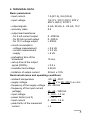
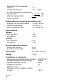
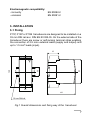
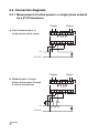
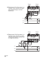
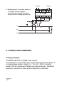
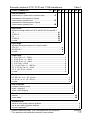
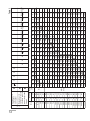
POWER TRANSDUCERS FOR SINGLE-PHASE AND THREE-PHASE NETWORK P11P, P13P and P13B 01 90 A O IS K I F Y T R E C 45 ´ 120 ´ 100 mm SERVICE MANUAL 1 T Contents Page 1. APPLICATION .......................................................................... 3 2. BASIC REQUIREMENTS ......................................................... 3 3. TRANSDUCER SET ................................................................. 4 4. TECHNICAL DATA ................................................................... 5 5. INSTALLATION ........................................................................ 7 5.1. Fixing ................................................................................. 7 5.2. Connection diagrams ........................................................ 8 5.2.1. Measurement of active power in a single-phase network ................................................................... 8 5.2.2. Measurement of active power in a 3-phase 3-wire network ......................................................... 9 5.2.3. Measurement of reactive power in a 3-phase 3-wire network ........................................................ 11 6. CODING AND ORDERING .................................................... 12 7. MAINTENANCE AND GUARANTEE ..................................... 15 2 1. APPLICATION The P11P transducer is destined for the conversion of active or reactive a.c. power into a d.c. current or d.c. voltage standard signal. The input, output and supply circuits are galvanically isolated (transformer separation) The conversion frequency range enables the correct measurement of power when currents and voltages are distorted (up to 25 th harmonic). The pulse feeder ensures the operation in a width range of values and frequency of the supply voltage. The measurement is realised through the analogue multiplier function with the pulse modulation (TDM). These transducers are destined to operate in industrial conditions and can be mounted in optional position. Transducer housings are made of a self-extinguishing plastic and are adapted to be fixed on 35 mm DIN rail (DIN EN 50 022-35). P11P - transducer destined for active power measurement in a single-phase network. P13P - transducer destined for active power measurement in a symmetrically loaded 3-phase 3-wire network. P13B - transducer destined for reactive power measurement in a symmetrically loaded 3-phase 3-wire network. 2. BASIC REQUIREMENTS, OPERATIONAL SAFETY Symbols located in this service manual mean: Especially important, one must acquaint with this before connecting the transducer. The non-observance of notices ! marked by these symbols can occasion the damage of the transducer. ? One must take note of this when the transducer is working inconsistently to the expectations. In the security scope the transducer meets the requirements of the EN 61010-1 standard. 3 Remarks concerning the operator safety: ! P11P, P13P and P13B transducers are destined to be mounted on 35 mm DIN rails. In the range of operational safety they are in conformity with the EN 61010-1standard requirements. l The installation and transducer connection should be operated by a qualified personnel. l One must take into consideration all accessible protection requirements. l Before switching the instrument on, one must check the correctness of the network lead connection. l In case of the protection terminal connection with a separate lead one must remember to connect it before the connection of network leads. l Do not connect the instrument to the network through an auto-transformer. l Before taking the transducer housing out, one must turn the supply off. l The removal of the transducer housing during the guarantee contract period may cause its cancellation. The programmer connector is destined only for the PD11 programmer connection. After the transducer programming, one should put the hole plug of the programmer connector. 3. TRANSDUCER SET The transducer set includes: - P11P or P13P or P13B transducer 1 pc - service manual 1 pc - guarantee card 1 pc 4 4. TECHNICAL DATA Basic parameters: - input current 1 A (X/1 A), 5 A (X/5 A) - input voltage 10/Ö3 V, 100 V, 230 V, 400 V, 500 V, 690 V, X/100 V - output signals 5 mA, 20 mA, 4...20 mA, 10 V - accuracy class 0.5 - output load resistance: - for 5 mA current output - for 20 mA current output - for 10 V voltage output 0...2000 W 0...500 W ³ 500 W - circuit consumption: - voltage measurement - current measurement - supply £ 0.6 VA £ 0.3 VA £ 6 VA - preheating time of the transducer - set-up time of the output signal (0/90%) - insulation test voltage - limitation of output current 15 min. £ 0.5 s 3.25 kV 28 mA ± 10% Nominal reference and operating conditions: - ambient temperature -20...23...55°C - supply voltage 18...40 V or 85...253 V a.c./d.c. - frequency of the supply voltage 40...400 Hz - frequency of the input current 45...65...1250 Hz (voltage) - input voltage 0...0.01...1.2 Un - power factor (cos fi) - 1...0...1 - input current 0...0.01...1.2 In - peak factor of the measured current £3 5 - peak factor of the measured voltage £2 - storage temperature - 25... + 85°C - air relative humidity (condensation inadmissible) 0... 45...75...85% 0...40...400 A/m - external magnetic field - working position any Additional Errors caused by the influence of: - frequency of the input quantity < 0.05 k/100 Hz - ambient temperature < 0.5 k/10°C - external magnetic field < 0.1 k/100 A/m. Input overload: Voltage: - short duration - long-lasting 2 Un 1.2 Un Current: - short duration - long-lasting 10 In 1.2 In Ensured protection degree: - through the housing - from the terminal side IP 50 IP 20 Dimensions: 45 x 100 x 120 mm Weight: 210 g Compliance to standards: - service security, requirements and tests - insulation ensured by the housing - insulation between circuits - installation category - pollution level - maximal working voltage in relation to earth 6 EN 61010-1 double basic III 2 600 V Electromagnetic compatibility: - immunity - emission EN 50082-2 EN 50081-2 5. INSTALLATION 5.1 Fixing P11P, P13P or P13B transducers are designed to be installed on a 35 mm DIN rail acc. DIN EN 50 022-35. On the external side of the transducer there are screw or self-locking terminal strips enabling the connection of 2.5 mm2 external leads (supply and output) and up to 1.5 mm2 leads (input). 41 93 35 120 P11P 45 100 35 mm DIN rail Fig.1 Overall dimensions and fixing way of the transducer 7 5.2. Connection diagrams 5.2.1. Measurement of active power in a single-phase network by a P11P transducer. Supply Output + a) Direct measurement of single-phase active power 9 10 15 16 P11P 1 2 3 5 L1 N or L2 Supply b) Measurement of singlephase active power through a current transformer Output + 9 10 15 16 P11P 1 2 3 L1 N or L2 8 S1 S2 P1 P2 5 Supply Output + c) Measurement of single-phase active power through a current and voltage transformer 9 10 15 16 P11P 1 2 3 L1 a b A B 5 S1 S2 P1 P2 N or L2 5.2.2. Measurement of active power in a 3-phase 3-wire network by a P13P transducer (Symmetrically loaded) Supply a) Direct measurement of active power in a 3-phase 3-wire network symmetrically loaded Output + 9 10 15 16 P13P 1 2 3 5 8 L1 L2 L3 9 Supply Output + b) Measurement of active power in a 3-phase 3-wire network symmetrically loaded through a current transformer 9 10 15 16 P13P 1 2 3 L1 S1 S2 P1 P2 8 5 L2 L3 Supply c) Measurement of active power in a 3-phase 3-wire network symmetrically loaded through a current and a voltage transformer L1 L2 L3 10 9 10 15 16 P13P 1 2 3 a b a b A A B B Output + S1 S2 P1 P2 5 8 5.2.3. Measurement of reactive power in a 3-phase 3-wire network by a P13P Transducer (Symmetrically loaded) Supply Output + a) Direct measurement of reactive power in a 3-phase 3-wire network symmetrically loaded 9 10 15 16 P13B 1 3 5 8 L1 L2 L3 Supply Output + b) Measurement of reactive power in a 3-phase 3-wire network symmetrically loaded through a current transformer L1 9 10 15 16 P13B 1 3 S1 S2 P1 P2 5 8 L2 L3 11 Supply c) Measurement of reactive power in a 3-phase 3-wire network symmetrically loaded through a current and a voltage transformer L1 Output + 9 10 15 16 P13B 1 a b A B 3 S1 S2 P1 P2 5 8 L2 L3 6. CODING AND ORDERING Coding example: The P11P- A1-C-1-1-1-00-0 code means: the execution of a transducer for measurement of active power in a single-phase system, input: In = 1 A, Un = 230 V, nominal power: 200 W, permanent fastening screw terminals, standard execution, without an extra quality inspection certificate. 12 Execution codes of P11P, P13P and P13B transducers POWER TRANSDUCER - P1 XX XX X Table 1 X X X XX X Kind of transducer: measurement of 1-phase active or reactive power ..................... 1P measurement of active power in 3-phase 3-wire systems, symmetric load ................................................... 3P measurement of reactive power in 3-phase 3-wire systems, symmetric load ................................................... 3B Input current: write down the range code (from A1 to Z1 and B5 to Z5) from the table 2: 1 A ......................................................................................................... A1 20 000/1 A ............................................................................................. Z1 5 A ......................................................................................................... B5 20 000/5 A ............................................................................................. Z5 on order * ............................................................................................... 99 Input voltage: write down the range code (from A to V) from the table 2: 100/Ö3 V ..................................................................................... A 400 000/100 V ................................................................................................ W on order * ........................................................................................................ 9 Output range: 0...5 mA, R obc. = 0... 2000 W ............................................................................................. 1 0...20 mA, R obc. = 0... 500 W ............................................................................................. 2 4...20 mA, R obc. = 0... 500 W ............................................................................................. 3 0...10 V, R obc. ³ 500 W ........................................................................................................4 -5...0...5 mA, R obc. = 0... 2000 W ...................................................................................... 5 -20...0...20 mA, R obc. 0... 500 W ....................................................................................... 6 -10...0...10 V, R obc. ³ 500 W .............................................................................................. 7 on order * ................................................................................................................. 9 Supply: 85...253 V d.c. or a.c. (40...400 Hz) ............................................................................... 1 18...40 V d.c. or a.c. (40...400 Hz) ................................................................................. 2 on order * .......................................................................................................................... 9 Kind of terminals: permanent fastening screws .................................................................................................... 1 socket - screw plug .................................................................................................................. 2 socket - self-locking plug .......................................................................................................... 3 Execution: standard .......................................................................................................................................... 00 custom-made * ................................................................................................................................. XX Acceptance test: without an extra quality inspection certificate ........................................................................................... 0 with an extra quality inspection certificate ................................................................................................ 1 acc users agreement* * ............................................................................................................................ X * Custom-made execution, one must agree with the producer * * The producer will settle the execution code number 13 14 P1 R1 C5 D5 E5 F5 G5 H5 I5 J5 K5 L5 M5 N5 P5 R5 S5 T5 U5 V5 10/x 15/x 20/x 30/x 50/x 75/x 100/x 150/x 200/x 300/x 400/x 600/x 800/x 1000/x 1200/x 1500/x 2000/x 3000/x V1 U1 T1 S1 N1 M1 L1 K1 J1 I1 H1 G1 F1 E1 D1 C1 B1 B5 5; 5/x A1 – x=1 In code x=5 1 ln/x 3B 3P 1P kW; kvar W Power unit Un [V] Measurement of 3-phase 3-wire active or reactive power in a symmetrically loaded network Measurement of single-phase active power B 100 80 60 40 30 20 15 10 7.5 5 3 2 1.5 1 150 300 100 200 80 150 60 120 50 100 40 30 20 15 10 8 5 4 2.5 1.5 1 800 500 250 500 50 100 A 3 100 D 400 2 80 60 40 30 20 12 7.5 6 4 600 1.2 400 800 300 600 250 400 200 400 150 300 120 200 80 150 60 120 40 30 20 15 10 6 4 3 2 1 200 400 C 230 G 400 H 500 60 50 30 20 12 10 6 3 4 80 50 30 20 15 10 5 1 80 100 60 40 25 15 12 8 I 690 1.5 1 750 2 1.2 1 800 800 1 2.5 1.5 1.2 3 2 1.5 1 1.2 500 600 800 400 500 600 800 300 400 500 600 200 250 300 400 150 200 250 300 100 120 150 200 75 100 120 150 50 30 25 15 10 7.5 5 2.5 500 600 800 E 500 50 10 L 80 15 M Un code 15 10 7.5 6 5 4 3 2 1.5 1 750 500 30 20 15 12 10 8 6 4 3 2 1.5 1 300 750 50 30 25 20 15 12 10 6 5 3 2.5 1.5 1.2 250 500 800 150 300 500 100 200 300 75 150 250 50 100 150 25 5 K 75 50 30 30 25 20 12 10 7.5 5 3 2.5 1.5 1.2 750 500 300 250 120 25 N 100 60 50 40 30 25 20 12 10 6 5 3 2.5 1.5 1 600 500 300 150 30 P 60 S 100 80 60 50 40 25 20 12 10 6 5 3 2 1.2 1 150 200 100 120 75 60 50 40 25 20 15 10 7.5 5 3 2.5 1.5 1 750 500 600 250 300 50 R 300 200 150 120 100 80 60 40 30 20 15 10 7.5 5 3 2 1.5 1 500 100 T V W 800 600 500 400 250 200 120 100 60 50 30 20 12 10 6 3 600 750 500 1000 400 300 300 200 150 100 75 50 30 25 15 10 7.5 5 3 1.5 300 300 1000 300 250 200 150 150 100 75 50 30 25 15 12 8 5 3 2.5 1.5 800 150 U 3 000 6 000 10 000 15 000 20 000 30 000 40 000 60 000 110 000 220 000 400 000 100 100 100 100 100 100 100 100 100 100 100 Table 2 500 400 600 1000 300 200 10 8 15 6 12 5 10 8 4 2 LUMEL S.A. reserves the right to make changes in design and specifications of any products as engineering advances or necessity requires. 2 4 2. After the guarantee period: One should turn over the transducer to repair it in a certified service workshop. Spare parts are available for the period of ten years from the date of purchase. 1 1 The P11P, P13P and P13B transducers do not require any periodical maintenance. In case of some incorrect unit operations: 1. In the 18 months period from the date of shipment: One should return the transducer to the LUMELs Quality Control Dept. If the unit has been used in compliance with the instructions, LUMEL S.A. guarantees to repair it free of charge. The disassembling of the housing causes the cancellation of the granted guarantee. Z5 20000/x Z1 Y5 10000/x Y1 X5 6000/x X1 W5 4000/x W1 MW; Mvar 500 20 50 100 150 600 1000 1200 750 400 100 200 300 300 400 150 200 250 200 100 60 60 100 40 20 4 6 3 5 2 4 2 1.5 800 1.2 300 600 200 400 3 2.5 30 120 600 1000 7 . MAINTENANCE AND GUARANTEE 15 Lubuskie Zak³ady Aparatów Elektrycznych LUMEL S.A. ul. Sulechowska 1 65-950 Zielona Góra - Poland Tel.: (48-68) 329 51 00 (exchange) Fax: (48-68) 329 51 01 e-mail: [email protected] http://www.lumel.com.pl Tel. (48-68) 329 52 38 Fax (48-68) 325 40 91 e-mail: [email protected] April 2002 Export Department: