1
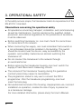
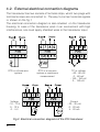
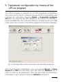
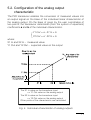
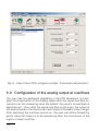
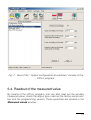
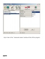
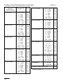
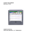
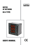
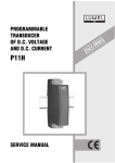
TRANSDUCER of TEMPERATURE and STANDARD SIGNALS P20 type USER’S MANUAL Contents 1. APPLICATION ........................................................................................... 5 2. TRANSDUCER SET ................................................................................... 5 3. OPERATIONAL SAFETY ............................................................................ 6 4. INSTALLATION ......................................................................................... 7 4.1.Fitting way ..............................................................................7 4.2.External electrical connection diagrams ...............................8 5. TRANSDUCER CONFIGURATION BY MEANS OF THE LPCon PROGRAM ....................................................................... 9 5.1.Configuration of the transducer input type ..........................10 5.2.Configuration of the individual analog output characteristic ............................................................11 5.3.Configuration of the analog output at overflows ..................12 5.4.Readout of the measured value ..........................................13 6. TECHNICAL DATA . ................................................................................. 15 7. EXECUTION CODES ................................................................................ 17 8. MAINTENANCE AND GUARANTEE . ........................................................ 19 1. APPLICATION The P20 programmable transducer is designed to convert temperature, resistance, voltage from a shunt and standard signals into a constantcurrent or constant-voltage standard signal. The output signal is galvanicaly isolated from the input signal and supply. The transducer compensates automatically the resistance of wires in case of resistance value measurements in a three-wire system and automatically compensates the temperature of terminals in case of measurements from thermocouples. The transducer is fully configurable through the PD14 programmer. By means of this programmer, one can change the input type, the measurement averaging time and rescale the analog output acc. to the individual output characteristic, and also read out the measured value. 2. TRANSDUCER SET The set of the P20 transducer is composed of: - P20 transducer 1 pc. - User’s manual 1 pc. - Guarantee card 1 pc - Plug with screw terminals 2 pcs. - Hole plug of the programmer socket 1 pc When unpacking the transducer, please check whether the type and execution code on the data plate correspond to the order. 3. OPERATIONAL SAFETY In the safety service scope, the transducer meets to requirements of the EN 61010-1 standard. Observations concerning the operational safety l All operations concerning transport, installation, and commissioning as well as maintenance, must be carried out by qualified, skilled personnel, and national regulations for the prevention of accidents must be observed. l Before switching transducer on, one must check the correctness of connections to the network. l When connecting the supply, one must remember that a switch or a circuit-breaker should be installed in the building. This switch should be located near the device, easy accessible by the operator, and suitably marked as an element switching the transducer off. l Do not connect the transducer to the network through an autotransformer. l Before removing the transducer housing, one must switch the supply off and disconnect measuring circuits. l The removal of the transducer housing during the guarantee contract period may cause its cancellation. l The programmer socket is only use to connect the PD14 programmer. After the transducer programming, one must insert the hole plug. l Non-authorized removal of the housing, inappropriate use, incorrect installation or operation, creates the risk of injury to personnel or a transducer damage. For more detailed information, please study the User’s Manual. 4. INSTALLATION 4.1. Fitting way P20 transducers are designed to be mounted on a 35 mm rail accor- ding to EN 60715. The transducer housing is made of a self-extinguishing plastic. Housing dimensions are: 22.5 x 120 x 100 mm. On the transducer outside, there are screw or self-locking terminal strips, which make possible the connection of external wires with a 2.5 mm2 cross-section (supply and output) and up to 1.5 mm2 (input). Connector of the PD14 programmer Fig. 1. Overall dimensions and fitting way of the transducer 4.2. External electrical connection diagrams The transducer has two sockets of terminal strips, which two plugs with terminal screws are connected to. The way to connect external signals is shown on the fig.1 The electrical connection diagram is also situated on the transducer housing. In case of the transducer work in an environment with high interferences, one must apply shielded wires in the transducer input. RTD in a three-wire system Voltage - 10... 10 V 0... 10 V 0... 5 V RTD in a two-wire system or resistance measurement TC or voltage - 60... 60 mV 0... 60 mV - 150... 150 mV 0... 150 mV Current - 20... 20 mA 0... 20 mA 4... 20 mA Fig.2. Electrical connection diagrams of the P20 transducer. 5. Transducer configuration by means of the LPCon program The LPCon program is destined for the P20 transducer configuration. One must connect the PC computer through the PD14 programmer and configure the connection choosing Option -> Connection configuration from the menu (for the P20 transducer, we choose the address 1, baud rate 9600 kb/s, the mode RTU 8N2 and the appropriate port COM under which the controller of the PD14 programmer has been installed). Fig. 3. Configuration of the connection with the P20 transducer. After the connection configuration, one must choose Device -> Transducers P -> P20 from the menu, and next click the Readout icon in order to read out all parameters. One can also read out parameters individually in each group clicking the Refresh push-button. 5.1. Configuration of the transducer input type Three developable lists are accessible in the parameter group “Input configuration”, by means of which, one can choose the input type, the measuring range and the measurement averaging time. One must confirm changes, clicking the Apply push-button. Fig. 4. View of the LPCon program window “Input configuration” 10 5.2. Configuration of the analog output characteristic The P20 transducer enables the conversion of measured values into an output signal on the base of the individual linear characteristic of the analog output. On the base of given by the user coordinates of two points, the transducer determines (from the system of equations) coefficients a and b of the individual characteristic. Y1 Out = a . X1 In + b Y2 Out = a . X2 In + b where: X1 In and X2 In – measured value Y1 Out and Y2 Out – expected value on the output The X1 In value on the transducer input => Y1 Out value on the analog output The X2 In value on the transducer input => Y2 Out value on the analog output Other points of the characteristic are calculated Fig. 5. Individual characteristic of analog outputs 11 Fig. 6. View of the LPCon program window “Individual characteristic” 5.3. Configuration of the analog output at overflows The user has the additional possibility in the P20 transducer to confi- gure the preservation of the analog output after the signal overflow occurrence on the measuring input. By default, the service of overflows is switched out – then, after the signal overflow on the input, the output is still proportional to the steered up input beyond the basic output range. After switching the overflow service on, the user can define himself by which value the output is to be steered up after the occurrence of the higher or lower overflow. 12 Fig. 7. View of the “ Output configuration at overflows” window of the LPCon program. 5.4. Readout of the measured value By means of the LPCon program, one can also read out the actually measured value, check the output type, read out the factory serial number and the programming version. These quantities are located in the Measured values window. 13 Fig.8. View of the “ measured values” window of the LPCon program 14 6. TECHNICAL DATA Basic parameters: - analog output galvanicaly isolated: - current - voltage - maximal load resistance of the current output - minimal load resistance of the voltage output - accuracy class1) - averaging time of the transducer: - range: d.c. current [mA], d.c. voltage [V] - other ranges - consumption - preheating time of the transducer - transducer response time: - range: d.c. current [mA], d.c. voltage [V] - other ranges - current flowing through RTD - resistance of wires connecting RTD with the transducer Rated operating conditions: - supply depending on the execution code - frequency of the supply a.c. voltage - ambient temperature - storage temperature - related air humidity - working position 0/4...20 mA 0...10 V £ 500 W ³ 500 W 0.2 ³ 0.1 s ³ 0.3 s < 3 VA 10 min ³ 0.2 s ³ 0.4 s < 0.2 mA 10 W 85... 253 V a.c./d.c. 20... 40 V a.c./d.c. 45... 65 Hz – 20...23...55°C – 25...85°C < 95% (condensation inadmissible) any 15 Input parameters: - resistance of voltage input [V] - resistance of current input [mA] > 1 MW 12 W ±1% Sustained overload: - TC and RTD - voltage, current and resistance 1.1 X n 1.3 X n Short duration overload: - voltage input - current input 5 Un 10 I n Ensured protection level acc. to EN 60529: - housing - from terminal side IP 40 IP 20 Dimensions: 22.5 ´ 100 ´ 120 mm Weight: 0.125 kg Fitting on a 35 mm DIN rail, acc. to EN 60715 Electromagnetic compatibility: - noise immunity - noise emission EN 61000-6-2 EN 61000-6-4 Safety requirements acc. to EN 61010-1: - installation category III - pollution degree 2 - phase-to-earth working voltage: - supply 300 V 2) - input 50 V - output 50 V - altitude above sea level < 2000 m 1)A part of sub-ranges for thermocouples and RTD has a specified individual class – see table 3 2)Execution for supply voltage 230 V. 16 7. EXECUTION CODES Execution codes of the P20 transducer Table 2. TRANSDUCER P20 - X X XX XX X Analog outputs: current 0... 20 mA....................... 1 current 4... 20 mA....................... 2 voltage 0... 10 V......................... 3 Supply: 85...253 V a.c./d.c..............................1 20...40 V a.c./d.c................................2 Kind of input see table 3................................................ XX Execution: standard........................................................... 00 custom-made*..................................................XX Acceptance tests: without extra quality requirements............................ 8 with an extra quality inspection certificate................. 7 acc. to customer’s requirements*.............................. X * after agreeing with the manufacturer 17 Coding of the P20 transducer input kind Type of sensor/input Pt100 RTD Pt 250 RTD Pt 500 RTD Pt1000 RTD TC of J type 18 Range [°C] Kod -200...850 0...850 0...600 0...400 0...200 -200...200 -100...100* 01 02 03 04 05 06 07 -200...850 0...850 0...600 0...400 0...200 -200...200 -100...100 08 09 10 11 12 13 14 -200...850 0...850 0...600 0...400 0...200 -200...200 -100...100 15 16 17 18 19 20 21 -200...850 0...850 0...600 0...400 0...200 -200...200 -100...100 22 23 24 25 26 27 28 -200...1200 0...1200 0...1000 0...800 0...600 0...400* -200...200* 29 30 31 32 33 34 35 Table 3. TC of K type -200...1200 0...1200 0...1000 0...800 0...600 0...400* -200...200* 36 37 38 39 40 41 42 TC of S type 0...1760 0...1600 0...1400* 0...1200* 0...1000* 43 44 45 46 47 TC of N type -200...1200 0...1200 0...1000 0...800 0...600* 0...400* -200...200* 48 49 50 51 52 53 54 d.c. voltage 0...10 V 0...5 V -10...10 V -5...5 V 0...60 mV -60...60 mV -0...150 mV -150...150 mV 55 56 57 58 59 60 61 62 d.c. current 0...20 mA 4...20 mA 0...5 mA -20...20 mA 63 64 65 66 Resistance 0...400 W 0...4000 W 67 68 Custom-made execution * accuracy class 0,5 XX Example of order: When ordering, please respect successive code numbers. The code: P20-1.1.04.00.7 means: P20 – transducer of temperature and standard signals 1 – with current analog output:: 0…20 mA, 1 – voltage supply: 85…253 V a.c./d.c., 04 – Pt100 input signal, 0…400°C range, 00 – standard execution 7 – with an extra quality inspection certificate 8. MAINTENANCE AND GUARANTEE The P20 transducer does not require any periodical maintenance. In case of some incorrect operations: After the dispatch date and in the period stated in the guarantee card: One should return the transducer to the Manufacturer’s Quality Inspection Dept. If the instrument has been used in compliance with the instructions, we guarantee to repair it free of charge. The disassembling of the housing causes the cancellation of the granted guarantee. After the guarantee period: One should turn over the instrument to repair it in a certified service workshop. Spare parts are available for the period of five years from the date of purchase. We reserves the right to make changes in design and specifications of any products as engineering advances or necessity requires. 19 SALES PROGRAM DIGITAL and BARGRAPH PANEL METERS MEASURING TRANSDUCERS ANALOG PANEL METERS (DIN INSTRUMENTS) MEASUREMENT CONTROL RECORDING DIGITAL CLAMP-ON METERS INDUSTRIAL PROCESS and POWER CONTROLLERS CHART and PAPERLESS RECORDERS 1-PHASE and 3-PHASE WATT-HOUR METERS LARGE SIZE DISPLAY PANELS ELEMENTS OF INTEGRATION SYSTEMS ACCESSORIES for MEASURING INSTRUMENTS (SHUNTS) CUSTOM-MADE PRODUCTS ACCORDING CUSTOMER’S REQUIREMENTS WE ALSO OFFER OUR SERVICES IN THE PRODUCTION OF: ALUMINIUM ALLOY PRESSURE CASTINGS PRECISION ENGINEERING and THERMOPLASTICS PARTS SUBCONTRACTING of ELECTRONIC DEVICES (SMT) PRESSURE CASTINGS and OTHER TOOLS QUALITY PROCEDURES: According to ISO 9001 and ISO 14001 international requirements. All our instruments have CE mark. For more information, please write to or phone our Export Department Lubuskie Zak³ady Aparatów Elektrycznych LUMEL S.A. ul. Sulechowska 1, 65-022 Zielona Góra, Poland Export Department: Tel.: (48-68) 329 53 02 Fax: (48-68) 325 40 91 e-mail: [email protected] 20 P20-07A Tel.: (48-68) 329 51 00 (exchange) Fax: (48-68) 329 51 01 e-mail:[email protected] http://www.lumel.com.pl