1
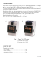
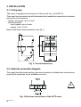
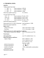
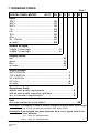
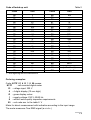
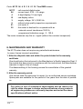
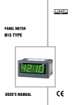
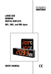
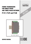
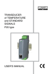
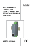
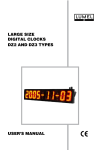
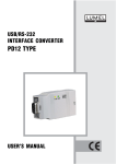
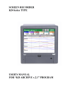
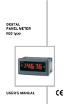
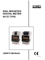
RAIL MOUNTED DIGITAL METER N17Z TYPE USER’S MANUAL RAIL MOUNTED DIGITAL METER N17Z TYPE USER’S MANUAL CONTENTS 1. APPLICATION...................................................................................5 2. METER SET......................................................................................5 3. BASIC REQUIREMENTS, OPERATIONAL SAFETY........................6 4. INSTALLATION.................................................................................8 4.1 Fixing way...................................................................................8 4.2 External connection diagram......................................................8 5. HANDLING........................................................................................9 6. TECHNICAL DATA..........................................................................10 7. ORDERING CODES.......................................................................12 8. MAINTENANCE AND WARRANTY.................................................14 October 2006 - KZ 1302/06 1. APPLICATION N17Z series meters mounted on 35 mm rail are destined to measure a.c.voltage and a.c. current (up to 500 V, 40 A) and frequency (up to 200 Hz). The meter measures the True RMS signal ( measurement with constant component) or only the variable component. Parameters which can be reprogrammed are given in the section 5-HANDLING. Parameters can be reprogrammed by distributors or in authorized workshops. The 3 or 4-digit readout field is available in red, green or blue colour. Overall dimensions of the meter: 52.5 ´ 90 ´ 64.5 mm (frontal frame = 52.5 ´ 45 mm). a) b) Fig. 1 View of the N17Z meter a) version with 3 digit b) version with 4 digits 2. METER SET The meter set includes: – N17Z meter.....................................................1 pc – user’s manual..................................................1 pc – warranty certificate..........................................1 pc 3. BASIC REQUIREMENTS, OPERATIONAL SAFETY Symbols located in this service manual mean: WARNING! Warning of potential, hazardous situations. Especially important, one must acquaint with this before connecting the module. The non-observance of notices marked by these symbols can occasion severe injuries of the personnel and the damage of the module. CAUTION! Designates a general useful note. If you observe it, handling of the meter is made easier. One must take note of this, when the meter is working inconsistently to the expectations. Possible consequences if disregarded ! In the security scope, the meter fulfils the requirements of the EEC Low-Voltage Directive (EN 61010 -1 issued by CENELEC). Remarks concerning the operator safety: 1. General The N17Z meter is destined to be installed in measuring systems. Non-authorized removal of the required housing, inappropriate use, incorrect installation or operation creates the risk of injury to personnel or damage to equipment. For more detailed information please study the user’s manual. All operations concerning transport, installation, and commissioning as well as maintenance must be carried out by qualified, skilled personnel and national regulations for the prevention of accidents must be observed. According to this basic safety information, qualified, skilled personnel are persons who are familiar with the installation, assembly, commissioning, and operation of the product and who have qualifications necessary for their occupation. 2. Transport, storage Please observe the notes on transport, storage and appropriate handling. Observe the climatic conditions given in Technical Data. 3. Installation The meter must be installed according to the regulation and instructions given in this User’s Manual. Ensure proper handling and avoid mechanical stress. Do not bend any components and do not change any insulation distances. Do not touch any electronic components and contacts. Meters may contain electrostatically sensitive components, which can easily be damaged by inappropriate handling. Do not damage or destroy any electrical components since this might endanger your health! Wire cross-sections must be chosen such to assure the protection of the cable in case of a short-circuit, by means of an installation cut-off. Requirements concerning the network cable are described in the EN 61010-1 standard. A cut-out or a circuit-breaker should be installed in the building and be easily accessible for the operator. 4. Electrical connection Before switching the meter on, one must check the correctness of connection to the network. In case of the protection terminal connection with a separate lead, one must remember to connect it before the connection of the meter to the mains. When working on live meters, the applicable national regulations for the prevention of accidents must be observed. The electrical installation must be carried out according to the appropriate regulations (cable cross-sections, fuses, PE connection). Additional information can be obtained from the user’s manual. The documentation contains information about installation in compliance with EMC (shielding, grounding, filters and cables). These notes must be observed for all CE-marked products. The manufacturer of the measuring system or installed devices is responsible for the compliance with the required limit values demanded by the EMC legislation. 5. Operation Measuring systems including N17Z meters must be equipped with protection devices according to the corresponding standard and regulations for prevention of accidents. After the instrument has been disconnected from the supply voltage, live components and power connections must not be touched immediately because capacitors can be charged. The housing must be closed during operation. 6. Maintenance and servicing Please observe the manufacturer’s documentation. Read all product-specific safety and application notes in this user’s manual. Before taking the meter out, one must turn the supply off. The removal of the meter housing during the guarantee period may cause its cancellation 4. INSTALLATION 4.1. Fixing way The meter is designed to be fixed on a 35 mm rail acc. to EN 60715. The meter has a terminal strip with terminals which enable the connection of external wires with cross-sections: - voltage, frequency: up to 3 mm2, - current versions: - input signals: up to 6 mm2 - supply: up to 3 mm2 Meter dimensions are presented on the fig. 2 Fig. 2 Overall dimensions 4.2. External connection diagram The supply must be connected by a two-wire conductor of suitable wire cross-section ensuring its protection by an installation cut-out. Fig. 3 Electrical connections of the N17Z meter The supply must be connected by a 2-wire cable of cross-section ensuring its protection by means of an installation cut-out. In case of current measurements, one must choose such a signal wire diameter that the flowing current does not cause the overheating of wires. 5. HANDLING After connecting external signals and switching the supply on, the meter automatically carries out the measurement and displays the measured value on the display field. The meter blanks insignificant zeros. In case of the lack of measuring signals, the meter shows the „0” value. The meter can be reprogrammed at the manufacturer, service workshops and distributors. One can reprogrammed following parameters: - kind of measured signals: a.c., a.c. + d.c. (TRMS), or d.c. - indication range, - indication recalculation, - decimal point, - measurement averaging time, - unit fading up (on/off). The appearance of following symbols on the display means: Overflow of the upper value of the programmed indication range Overflow of the lower value of the programmed indication range 6. TECHNICAL DATA INPUTS: Voltage measuring range: 1... 100 V 3... 300 V 5... 500 V input resistance 600 k input resistance 1,8 M input resistance 3 M Measuring signal frequency: 30...500 Hz Current measuring range: 0.01...1 A 0.05...5 A 0.1...10 A 0.4...40 A input resistance: 20 m ± 10% input resistance: 4 m ± 10% input resistance: 2 m ± 10% input resistance: 0.5 m ± 10% Measuring signal frequency: 30...500 Hz Measurement of 30...500 Hz frequency: input resistance 3 M Measuring signal amplitude: 5...600 V Basic error: - voltage and current - frequency 0,5% of the range ± 1 digit 0.1% of the range ± 1 digit Additional errors in rated operating conditions: - from ambient temperature changes (50% of the basic error/10 K) Peak factor: 1.7 Averaging time: min. 0.5 s (default value: 1 s) Rated operating conditions: - supply voltage - ambient temperature - storage temperature - relative air humidity - working position 230 V, 50/60 Hz ± 10% 110 V, 50/60 Hz ± 10% 24 V, 50/60 Hz ± 10% 24 V d.c. ± 10% - 10...23...55°C - 25... + 85°C < 95% (inadmissible condensation) any Sustained overload: 20% 10 Short duration overload (3 s): voltage input: 2 Un (< 1000 V) current input: 10 In Readout field: 3 LED digits (digit height: 14 mm) red, green or blue indication; range: - 199...999 4 LED digits (digit height: 10 mm) red, green or blue indication; range: - 1999...9999 Ensured protection degree from the frontal side: IP20 Dimensions: 52.5 x 90 x 64.5 mm Frontal frame: 52.5 x 45 mm Weight: < 0.25 kg Power consumption: < 6 VA Preheating time: 15 min. Electromagnetic compatibility: - immunity - emission 61000-6-2 61000-6-4 Safety requirements acc, to EN 61010-1 - installation category III - pollution level 2 - phase-to-earth working voltage 600 V a.c. 11 7. ORDERING CODES Digital panel meter Table 1 N17Z- XX X X X X XX ... Input: 100 V............................................................ 00 300 V............................................................ 01 500 V............................................................ 02 1 A................................................................ 03 5 A................................................................ 04 10 A.............................................................. 05 40 A.............................................................. 06 30... 500 Hz.................................................. 07 on order1...................................................... XX Number of digits: 3 digits, 14 mm high..............................................3 4 digits, 10 mm high..............................................4 Display colour: red................................................................................R green............................................................................G blue..............................................................................B on order 1.....................................................................X Supply voltage: 230 V 50/60 Hz................................................................... 1 110 V 50/60 Hz................................................................... 2 24 V 50/60 Hz..................................................................... 3 24 V d.c............................................................................... 4 on order 1............................................................................ X Acceptance tests: without extra quality requirements..............................................8 with an extra quality inspection certificate...................................7 acc. to customer’s requirements 1. ............................................ X Unit: unit code number acc to the table 2................................................. XX Description 1 (introduce in case of another indication than the meter input range) e.g. if for 5 we want the indication 300, write: 5/300. Description 2 (as standard, the meter measures the a.c.+d.c. signal, write if it is to be different) a.c. - only a.c. measurement or d.c. - only d.c. measurement ... 1) - after agreeing with the manufacturer. 12 Code of faded up unit Table 2 Code Unit Code Unit 00 01 02 03 04 05 06 07 08 09 10 11 12 13 14 15 16 17 18 19 20 21 22 23 V A mV kV MV mA kA MA C F K Hz kHz Ah kAh m/s m mm cm m km l l/s l/h 24 25 26 27 28 29 30 31 32 33 34 35 36 37 38 39 40 41 42 43 44 45 46 XX ms s h N kN Pa hPa kPa MPa bar rad k % rev rps rpm rph m/h km/h imp (without unit) on order 1) 1) - after agreeing with the manufacturer Ordering examples: Code: N17Z 01 4 G 1 8 00 means: N17Z - rail mounted digital meter 01 - voltage input: 300 V 4 - 4-digits display (10 mm high) G - green display colour 1 - supply voltage: 230 V, 50/60 Hz 8 - without extra quality inspection requirements 00 - unit code acc. to the table 2: V Meter for direct measurement with indication according to the input range. The meter measures True RMS signal (a.c.+d.c.) 13 Code: N17Z 04 4 R 3 8 01 30 True RMS means: N17Z 04 4 R 3 8 01 30 - rail mounted digital meter - current input: 0.05....5 A range - 4-digit display (10 mm high) - red display colour - supply voltage: 24 V, 50/60 Hz - without extra quality inspection requirements - unit code: A - the meter is destined to co-operate with an external current transformer 150/5 A, programmed indication range : 0...150 A The meter measures only the a.c. signal (without the constant component) 8. MAINTENANCE AND WARRANTY The N17Z meter does not require any periodical maintenance. In case of some incorrect operations: 1. After the dispatch date and within the period stated in the warranty certificate One should return the instrument to the Manufacturer’s Quality Inspection Dept. If the module has been used in compliance with the instructions, the Manufacturer warrants to repair it free of charge. The disassembling of the housing causes the cancellation of the granted warranty. 2. After the warranty period: One should send the instrument to repair it in an authorized service workshop. Spare parts are available for the period of five years from the date of purchase. Our policy is one of continuous improvement and we reserve the right to make changes in design and specifications of any products as engineering advances or necessity requires and revise the above specifications without notice. 14 15 SALES PROGRAM MEASUREMENT DIGITAL and BARGRAPH PANEL METERS CONTROL MEASURING TRANSDUCERS RECORDING ANALOG PANEL METERS (DIN INSTRUMENTS) ANALOG and DIGITAL CLAMP-ON METERS INDUSTRIAL and HOUSEHOLD CONTROLLERS CHART AND PAPERLESS RECORDERS POWER CONTROL UNITS and INVERTERS LARGE SIZE NUMERIC and ALPHANUMERIC DISPLAYS AUTOMOTIVE DASHBOARD INDICATORS ACCESSORIES FOR MEASURING INSTRUMENTS MEASURING SYSTEMS (ENERGY, HEAT, CONTROL) CUSTOM-MADE PRODUCTS WE ALSO OFFER OUR SERVICES IN THE PRODUCTION OF: ALUMINIUM ALLOY PRESSURE CASTINGS PRECISION ENGINEERING AND THERMOPLASTICS PARTS PRESSURE CASTING DIES AND OTHER TOOLS QUALITY PROCEDURES: According to ISO 9001 and ISO 14001 international requirements. All our instruments have CE mark . For more information, please write to or phone our Export Department Lubuskie Zak³ady Aparatów Elektrycznych LUMEL S.A. ul. Sulechowska 1, 65-022 Zielona Góra, Poland Tel.: (48-68) 3295 100 (exchange) Fax: (48-68) 3295 101 e-mail:[email protected] http://www.lumel.com.pl Export Department: Tel.: (48-68) 3295 302 or 304 Fax: (48-68) 3254 091 e-mail: [email protected]