1
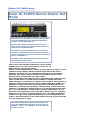
[Back to IC-F1000 Series]
Icom IC-F1000 Series Dealer Set
Mode
I
pinched some of the basis for this from a newsgroup
Not tried all of it yet, But I'm working through the
text and translating it into standard English and
giving it a more logical layout.
The IC-F2010 Dealer Set Mode allows access to
many of the commonly used parameters which are
otherwise set by PC software.
The software is fairly explanatory in use and has
help files. The Dealer Set Mode, however does not
and no explanation is given in the service manual as
to how to navigate it .
The main Dealer Set menu has six items and each
has submenus behind each.
The receive and transmit frequencies can be edited.
CTCSS tones for receive and transmit can be set up.
Alphanumeric tags can be edited.
Power on after alphanumeric editing and you will see a name or word
indicated on the display but the channel digit will not be shown.
The time out timer for your transmission period can be enabled or
disabled. This feature will be shown on the display as TOT in the
channel menu of the dealer set mode region.
The transmit RF power settings can be adjusted in the dealer channel
menu. ICOM refers to the RF power settings as flexible transmit.
Mute settings for continuous or single can be enabled. This function is
indicated on the Dealer channel menu as MUT CONT MUT SINGL. The
SELCALL TX Code channels for the sequence of RPT STN ID can be
disabled or enabled from the Dealer channel menu. It will not be my
intention to submit fine details because you will find that the EX1764
Ver 1.1 or CSF1000 Ver 1.2 HELP files are quite explanatory. If you
have the clone application just press the F1 button on your computer
keyboard for the clone software help file. You can enable something
similar to a roger beep type identification for your microphone PTT
button. This will indicate to the other station the end of your chat and
you are waiting for a reply.
The other definable parameters of the dealer set
mode are DTMF codes, RX Ch as in Rx ch code for
SELCALL. "TX Ch" as in SELCALL TX code channels
can be re-edited.
LIST relates to the scan banks and this region for
scanning can be set up from within the Dealer set
mode.
Channels can be disabled, enabled or re-assigned to
another scan bank from the LIST region of the
dealer set mode.
Priority scan channels A and B can be re-assigned.
The emergency answer back call channel can be reassigned. If the emergency answer back call
channel has been disabled it will be indicated as
EMR OFF ON the display.
You might choose to re-edit your power on welcome
message. The "actual position" for the re-editing of
the power on welcome message will be located
exactly between EMR OFF and COMMON. This will be
the sequence > EMR OFF - - - - - - - - COMMON.
Henceforth when you see eight dashes between EMR
OFF & COMMON the eight dashes will be the reediting section for the power on welcome message.
Entering Dealer Set Mode
First of all, initiate the radio by
powering up with [P0] and [Up]
pressed.
The screen will then display DEALER and the power
on bleep will be notable by it absence.
Next, enter the Dealer Passcode.
By default this is the usual Icom code of 159357
The Passcode can be changed in EX1764
As the keypad has only four numeric keys, the down
Arrow is used as a number and every button doubles
up so the actual sequence is
P1, P0, Dn, P3, P0, P2
The display will then show
SET MODE
Function buttons [P0] & [P1] are then used to toggle
between the 6 menu areas.
To exit Dealer Mode, simply power down with the
power button
The six main menu options are as shown in the table below. Use
[P3] then [Up] & [Dn] to change values
Displayed
(typical)
Chxx
COMMON
EX-1764
Equivalent
Values Notes
Submenu
01-32
Selects specific
or 01channel to edit
160
Rxxxxxxx
Txxxxxxx
RC ON/OFF
RC ON/OFF
Alphatag
TOT ON/OFF
Memory
PWR L1/L2/HI
Channel
MUT CONT/SGL
RPT xx
STN xx
ID xx
LOG
____/IN/INI/OFF/OFFI/BOTH
-
Priority A
Priority B
Emergency
Power-On Message
Various
LIST xx
xx ON/OFF
Scanbank Name
SCAN
MODE
LIST /
TEXT
LIST xx
01-10 Scan Groups
TXch xx
01-32 Selcall encode
TX Code
CH
RXch x
1-8
Selcall decode
(+G)
RX Code
CH
DTMF x
1-7
DTMF
DTMF
Autodial
Editing RX / TX Frequency
Transmit & Receive Inhibit
Power Adjust
Enabling Priority Channel
Editing DTMF
Editing TX / RX Frequency
Direct entry receive frequency edit via the front panel can be
accessed on the ICOM F1000 series.
(partly translated)
Buttons used in this operation are [P3] , [Up] and
[Dn]
Enter the dealer set mode. Have the channel number
indicated as steady. DO NOT! Let it blink. For
example you might have a blank frequency shown
as R:000000 .
To access the receive frequency section begin at the
channel digit and scroll down with the channel down
button. The receive frequency editing section will be
the first item directly after the channel number. You
will see the letter R in uppercase at the extreme left
of the display. There will be seven digits for editing.
As you begin editing it will be obvious that the four
zeros will be blinking separately or independent of
each other. The last three zeros or digits can not be
edited separately and will blink as the final
increment of three zeros or three digits together.
Depending on which channel you wish to perform
direct entry edit on just press the [P3] button. The
channel number will blink. While the channel
number is blinking push the channel up or down
button to scroll to the channel you have chosen to
edit. Push [P3] to stop the channel digit flashing.
Now press the [Dn] button and scroll to the receive
frequency editing section. Press [P3] to start
frequency editing. The first receive digit will blink.
While the digit is blinking push channel up or down
to select a number. Now push [P3] to enter the
number. The number will be entered automatically.
Use [P3] to continue editing. The next number will
blink .Press the channel up or down to choose a
digit. Press [P3] to save the value and move on to
the next decade. Continue setting each digit as
previously. When you get to the first of the last
three digits, you will note that they all flash in
unison. You will then be incrementing /
decrementing the last three digits (plus one hidden
in the case of 6.25kHz channel steps. The display
will step through all allowable values arising from
all usable channel rasters.
Push [P3] to save the value which will return the
display from blinking to steady. A similar procedure
is used for setting the transmit frequency, only the
displayed frequency begins with the letter 'T'.
Transmit & Receive Inhibit
The receive and transmit frequencies can be inhibited from the
dealer region for the IC-F1000 series.
Enter dealer set mode. Select the required channel
in at the channel number and scroll to the receive
frequency edit section with the channel down
button. Direct entry receive frequency section will
be indicated with the letter R on the left hand side
of display. Press the [P2] to inhibit the receive.
Frequency will be omitted and the text of R----INH
will appear.
If you have no need to restrict the receive just press
[P2] .
The R----INH will be replaced with the original
receive frequency. To inhibit the transmit frequency
use the same operational procedure. Direct entry
transmit frequency edit section will be indicated
with the letter T in uppercase at the left hand side of
radio screen.
When pushing [P2] for transmit inhibit the
frequency readout will be replaced with the text of
T---- INH . To disable transmit restricted just press
[P2] again. The text will be replaced with the
original transmit frequency.
Assigning Priority Channels
The priority A or B channel can be re-assigned in the dealer set
mode for the IC-F2010.
This will depend on how you have set up the scan
system in the cloning application. Enter the dealer
set mode. Press the PO or P1 button to scroll to the
word of COMMON. Begin at the word COMMON and
push the channel up or down button to scroll to PRA
or PRB. PRA means priority A channel. PRB
represents priority B channel. Will submit an
example. My current priority indication is PRA160.
I have chosen to re-assign a different channel for
priority scan channel A. Press P3 and the digit 160
will blink. The text of PRA will be steady and only
the channel digit will blink. While 160 is blinking I
press the channel up or down button to make a
selection. Have chosen channel 140 as the new
priority scan channel. Push P3 and the digit of 140
stops flashing. So now PRA 140 will be indicated as
the new priority scan channel A. Now exit dealer
mode and power off. Power on and then begin the
priority scan on the new priority A channel that I reassigned from
the dealer set mode.
Emergency Answer Back Call
The emergency answer back call channel can be re-assigned in
the ICOM F2010 Dealer set mode region.
The operational procedures will be enabled by the
use of the programmable assign buttons under the
radio display. A portion of the procedure will involve
the use of the channel up and down buttons.
Obviously the emergency answer back call would
need to be basically set up in the clone software.
The buttons used would be PO or P1, P2 , P3 and
channel up or down buttons in the dealer mode
region.
Enter the dealer set mode. Press [PO] or [P1] to
scroll to the text of "COMMON". Beginning at the
text of "COMMON" scroll with the channel up or
down button so that "EMR OFF" is shown on the
screen. EMR OFF means that the emergency answer
back call has been disabled. If you prefer to enable
an emergency answer back call channel just press
the [P2] button. The text of "EMR OFF" will be
omitted and for example EMR 24 might be indicated.
To re-assign a different channel for emergency call
press the [P3]button. EMR 24 will be indicated but
the digit 24 will blink. The actual text of "EMR" will
be steady and only the channel number will flash.
While the channel digit is blinking just push channel
up or down button to scroll to a new channel.
For example I have chosen channel 27 as a new
emergency answer back call channel. I press the
[P3] button and the digit 27 stops blinking. The
display now shows EMR 27.This will mean that
channel 27 is now the re-assigned and new
"Emergency answer back call channel" Have decided
that there is no need for this function and will
disable it. So now I press the [P2] button to cancel
the operational parameter. EMR 27 will be omitted
from the screen and now EMR OFF is indicated on
the radio display.
Editing Power-On Message
The power on welcoming message for the Icom F2010 can be reedited without connecting it to a PC or laptop
Enter the Dealer set mode. Have the channel
number showing steady. DO NOT! let it blink.
Now press PO or P1 to scroll to the item of
COMMON. The text of COMMON in uppercase letters
will be indicated on the display. Leave the word
COMMON on the display and the next procedure is to
press the channel up or down button to scroll to the
Power on welcome message re-editing region. This
re-editing section for the power on comment will be
positioned exactly between EMR OFF and COMMON.
When you scroll with the channel up or down
button ,PRA, PRB and EMR OFF will be shown on the
display. PRA PRB are the priority scan channels A
and B which can be reassigned. The EMR OFF means
the emergency answer back call has been disabled.
So to find the re-editing section scroll with your ch
up or ch down button to exactly between EMR OFF
and COMMON.
I will submit an explanatory sequence. Enter dealer
mode. Leave the channel number STATIC! as in NOT
Blinking. Press PO or P1 to scroll to the text of
"COMMON" Leave the text "COMMON" on the
display. NOW press a channel button to scroll to the
positon of [_ _ _ _ _ _ _ _] which will be positioned
exactly between EMR OFF and COMMON. The eight
dashes inside the brackets Is my way of indicating
how
the editing region will be positioned between EMR
OFF > [_ _ _ _ _ _ _ _] < & COMMON. Next press the
[P3] button and you will see a blinking effect on the
display. Leave it in blinking mode and then press
your ch up or down buttons to choose a character.
There will be a choice of numbers, symbols,
lowercase & uppercase letters. Press [P3] to stop a
blinking character and to enter the character.
Continue the procedure for the re-editing of the
welcoming power on message. The eight dashes will
signify that there is a limit of eight characters. This
procedure will be effective after you exit Dealer
mode, power off and then power ON. If you have
initiated the procedure correctly there should be a
new power on welcoming message.
Editing SELCALL TX Codes
The ICOM IC-F2010 SELCALL transmit channel codes 1 to 32 can
be re-edited from the Dealer set mode region.
Enter the dealer set mode. Now press [PO] or [P1]
to scroll to TX Ch 01. Have "TX ch 01" visible on the
radio display. For example i have chosen to re-edit
Tx ch 20. Press [P3] and 01 will blink. The text of
"TX ch" will remain steady and only the number will
flash on and off. While the 01 is blinking just press
the channel up or down button to scroll to the digit
of 20.
Now press [P3] to stop digit 20 from blinking. The
number is steady. While the number is static just
press the channel up or down button to scroll to the
SELCALL editing region. This SELCALL re-edit section
will be indicated with an abstract symbol at the
extreme left of the radio display. After this symbol
something like A E A E A E A might be indicated on
the screen. Obviously A is for group status and E
represents repeat. To begin editing just press the
[P3] button. The letter will begin blinking. While the
letter blinks just push the channel up or down
button to make a selection. The choices will be 0 1 2
3 4 5 6 7 8 9 or A B C D E. Press [P3] and the chosen
letter or digit will be entered automatically. Now the
next number or letter will begin flashing. Use
channel up or down to select a preference. Once
again push the [P3] button to enter the selection
automatically. Continue the procedure to finish re-
editing the SELCALL transmit channel code. To exit
the SELCALL code editing region just press channel
up or down button. I have exited this section and
now Tx ch 20 is indicated on the screen. All of the
SELCALL TX Channel codes 1 to 32 can be re-edited
within the Dealer Set Mode. The main set up can be
configured via the cloning application.
Receive & Transmit Inhibit
The receive and transmit frequencies can be inhibited for the
ICOM IC-F2010 by virtue of the dealer set mode.
show options
Enter the dealer region. Have the channel number
indicated on the display. DO NOT let it blink. Begin
at the channel digit and press the channel down
button. The receive frequency section will be the
first item immediately after the channel number.
This region will be clearly defined with an uppercase
"R " at the extreme left of the display. There will be
a programmable assign button under the radio
screen clearly designated as [P2]. To inhibit the
receive frequency just press the [P2] button. The
current receive frequency will be omitted and
replaced with an indication of " R- - - INH ".
Obviously the INH will signify that the frequency
has been Inhibited. If you have no need to restrict
the receive just push [P2] and the original receive
frequency will be shown on the screen. Press
channel down to scroll to the transmit frequency
editing region. This section will be defined as such
by an indication of the letter " T " at the extreme
left of the radio display. To inhibit the transmit
frequency just press the [P2] button. The original
frequency will be omitted and replaced with the
operational status indication of " T- - - INH
".Should you prefer to test the inhibit function exit
the dealer mode. Now power on and press the
microphone PTT button. There will be a sound
effect. When pushing the PTT a sound will be heard
meaning that the transmit inhibit is currently
activated. To disable the transmit inhibit just press
the [P2]button.Now the T- - -INH will be replaced
with the original transmit frequency indicated on
the radio screen.
Editing SELCALL TX Codes continued view as tree show options
You can also enter alpha numerics to edit a name or
a word for the SELCALL TX channel codes via the
dealer set mode. TAKE NOTE: In the context of the
ICOM F2010 dealer mode the actual SELCALL edit
and name editing are two separate sections. These
editing regions will be distinctly separate. The
SELCALL edit area will be clearly designated with an
abstract symbol at the extreme left of the display.
The text editing region will be represented by eight
dashes. For example i have entered the text of
GANGSAW for TX Code channel 29.Tx code channel
29 is the station code channel for the IC-F2010.Will
submit an explanation. My SELCALL for Tx code
channel 29 is A E A E A and is the station code. From
the dealer mode if i press the channel down button
this will be the sequence > TX Ch29 AEAEAEA
GANGSAW TX Ch29.From the dealer mode if i press
the channel up button beginning at TX Ch29 this will
be the sequence TX Ch29 > GANGSAW > AEAEAEA >
TX Ch29.So obviously the significance of the
sequence is quite explanatory. As you can see the
text and SELCALL edit sections will be very distinct.
Because TX Code channel 29 is the station code i
have decided to re-edit it to "STATION" within the
dealer set mode region. Will now submit an
explanation of the operational procedure. Enter the
dealer set mode. Activate the six digit passcode on
the programmable assign buttons via the radio front
panel. SET MODE appears on display. Press [PO] or
[P1] to enter the dealer region .You may see Ch O1
on the radio screen so disregard this. Now push
[PO] or [P1] to scroll the dealer menu until "TX
ChO1" is indicated on your screen. Leave the TX
ChO1 intact and push the [P3] button. The text of
"Tx ch" will remain steady but the digit "O1" will
blink. While "O1" is blinking press the channel up or
down button to scroll to the number of 29.To stop
the digit "29" blinking just press the [P3] button.
Leave the 29 as steady but now press channel down
or up to scroll to the text editing region. TAKE NOTE:
DO NOT confuse the text edit section with the
SELCALL edit region. You will notice that i previously
explained the SELCALL editing region being
indicated with an abstract symbol at the extreme
left of the display. If you have no text entered via
the clone software the text edit region will have
eight dashes. I will now re-edit my text of
GANGSAW to STATION. Press [P3] and the letter
"G" blinks. While G is flashing push channel up or
down to select the letter "S".Push [P3] and the S
will be entered automatically. Now the letter "A"
will blink so i press channel up or down to select the
letter "T". Press [P3] and the T will be entered. I
continue the previous editing procedure until the
text of STATION is indicated on the display. To exit
the alphanumeric editing section just push the
channel up or down button to return to Tx ch29.Any
of the SELCALL TX Code channels 1 to 32 can have
alphanumeric text editing set up by virtue of the
dealer set mode. This function will be effective after
exiting dealer mode,power off and then power on.
Editing DTMF
The DTMF codes can be edited in the dealer set mode. There will
be a choice of 7 DTMF codes for editing.
Enter the dealer mode. Now press the [PO] or [P1]
button to scroll the items until DTMF 1 is indicated
on the display. Push the [P3] button and the DTMF
code channel will blink. The text of DTMF will remain
steady but the digit will flash. Press channel up or
down button while digit is blinking to scroll to the
preferred DTMF code channel for editing. Press [P3]
to stop number blinking. Now push the channel up
or down button to enter the editing section. You will
see six dashes and an abstract symbol at the
extreme left of the display. Push [P3] to commence
edit. The first dash will blink and the digit " 1 " will
be visible above the abstract symbol. While the first
dash is flashing press the channel up or down
button to select your choice. For example you can
choose from A B C D E F or * 0123456789.Press
[P3] and the letter or digit will be entered
automatically. Now the second dash will blink. Push
channel up or down to select a number or letter.
Press [P3] to enter the selection. Continue the
editing procedure for all six dashes. On the sixth
dash the next edit section will be accessed
automatically. The second edit section will have the
digit " 2 " indicated above the abstract symbol. This
region will have six dashes. Use the previous editing
procedure for this section. When the six dashes
have been edited the last edit section will be
accessed automatically. This will be the last editing
section and will be indicated with the digit " 3 "
above the abstract symbol. The last region will only
have four dashes to configure. Once again use the
previous editing procedure to set up bank 3.When
you have configured Bank 3 it will automatically
return to bank 1. To exit the DTMF code editing
region just push the channel up or down button.
There will be 7 DTMF code channels for
configuration.Henceforth 3 editing banks per code
channel.
Scan Bank Reconfiguring
The scan banks for the ICOM F2010 can have channels disabled
from them or enabled via the dealer set mode.
Channels from a separate scan bank can be reassigned to a different scan group.
The operational procedures can be activated on scan
banks 1 to 10.
In the dealer set mode the scan banks will be
indicated as LIST 01, LIST 02, LIST 03 and so forth.
If you have entered text as in a name or word for
the scan bank via the clone software the text will be
indicated in the dealer set mode.
Enter the dealer mode. Press the PO or P1 button to
scroll the menu until LIST 01 is indicated on the
display. Press [P3] and the text of ' LIST ' will
remain steady but the scan bank number ' 01 ' will
blink. To stop the scan bank digit '01' blinking just
push [P3].As was mentioned previously all ten scan
banks can be reconfigured. Depending on which
scan group you are organising just press [P3] to
make the scan group digit blink. Now while the scan
bank number is blinking just press the channel up or
down button to scroll to your preference of scan
group. I will now submit an explanatory operational
procedure. Enter dealer set mode and push [PO] or
[P1] to scroll to 'LIST O1'. Press [P3] and the scan
bank digit '01' will blink. The text of 'LIST' will
remain steady. Push [P3] to stop the digit blinking.
Now I push the channel button so that '01 ON' is
indicated on the display. The 'ON' means that
channel one has been enabled for 'LIST 01' or scan
bank One. 'LIST 01' is my scan bank for the
repeaters 1 to 8. I push [P3] and the channel '01'
blinks. While the '01' is blinky push the channel up
button to check that DUPLEX 1 to DUPLEX 8 have
been enabled for 'LIST 01' or scan bank One. My
display will show this sequence: 01 ON 02 ON 03 ON
O4 ON 05 ON 06 0N 07 ON 08 0N.For example
Duplex 8 is quiet and i have chosen to disable it
from the scan group. While the '08' is flashing just
press the [P2] button to disable it from the scan
bank. Now the display status will show as '08' OFF.
TAKE NOTE: To enable or disable a channel from a
scan bank it must be done while the channel
number is 'BLINKING!' and by pressing the [P2]
button. Press [P3] to stop the channel digit blinking.
To re-enable channel 8 just push the [P3] button
and let the number 8 blink but while it is flashing
just press the [P2] button. Now the radio screen
indication will be '08 ON'. To organise the remaining
scan banks the previous operational procedures can
be utilised. If you have text entered for a scan bank
via the software it will be indicated in the dealer set
mode. Will submit an example of a sequence for the
dealer set mode: LIST 01 < SCAN ONE> 01 ON. LIST
10 <SCAN TEN> 160 ON. An explanation would be
that LIST 01 corresponds to scan bank one. LIST 10
is related to scan bank ten. Henceforth LIST 01 to
LIST 10 is an operational parameter. Press [P3] and
the list digit will blink. Scroll to the LIST (SCAN
BANK) that you prefer to organise. "SCAN TEN" is
just the text that you entered via the software. ' 160
ON' is also an operational parameter. Press [P3] and
the channel digit '160' will blink. To enable or
disable it from the scan bank just press the [P2]
button while it is blinking. Push [P3] to stop it from
flashing. Obviously 160 ON will signify that channel
160 is included for scan bank ten or LIST 10. 160
OFF will mean that channel 160 has been omitted
from the LIST TEN and will not be included as a
scanning channel for scan bank ten. Such is the
versatility of the IC-F2010 multi tasking realm by
virtue of the dealer mode that a channel from a
separate scan bank can be re-assigned to a different
scan group. Shall return with a continuation of this
article.
Update
As was mentioned in my previous article a channel
from another scan bank can be re-assigned to a
separate scan group.
I have chosen to disable Duplex 8 from 'LIST 01'
and will re-assign channel 160 to scan bank one
which obviously corresponds with 'LIST 01'. Have
LIST 01 shown on the radio display. Scroll to '01 ON'
with the channel up or down button.
Now push the [P3] button and the channel digit '01'
will blink. While the channel '01' is blinking press
the channel up button to scroll to channel '08'.Have
the 08 flashing and just press [P2].The screen will
now show the status of ' 08 OFF '. My next
operational procedure will be to re-assign channel
160 from LIST 10 or scan bank ten to scan bank one
which corresponds with 'LIST 01' that I am
currently on. The current screen indication will
appear as ' 08 OFF' but I need to scroll back to
channel 160 to re-assign it.
No problem. Push the [P3] button and the channel
digit '08' will flash. The text of 'OFF' will remain
steady. While the channel number is flashing my
finger presses the channel down to scroll back to
channel 160.The radio screen will show the
information status of ' 160 OFF'. I let the '160' blink
and then press on the [P2] button. Push [P3] to stop
the channel '160' from blinking. The radio screen
will now have an indication of '160 ON'.
HEY PRESTO! SENSATIONAL!
Channel 160 from 'LIST 10' has been re-assigned to
'LIST 01' which is my repeater scan bank.
Henceforth duplex 8 will not be included as a scan
channel for scan bank one as in 'LIST 01'.Channel
160 has been re-allocated and will now be included
as a scan channel for 'LIST 01'. TAKE NOTE: To
enable or disable a channel from a scan group it
must be done while the channel digit is 'BLINKING!'
and by pressing the [P2] button. So after pushing
[P2] while '160' was blinking the display indicated '
160 ON '.I have re-configured the scan banks in the
dealer mode region. Will now submit an example of
basically how it will be indicated.
LIST 10 SCAN TEN 160 OFF.
LIST 01 SCAN ONE 160 ON, 01 ON 02 ON 03 0N 04
ON 05 ON 06 0N 07 ON '08 OFF'.
All of the 'LIST' banks 1 2 3 4 5 6 7 8 9 10 are
operational parameters. Press the [P3] button to
make the LIST digit blink. While the Scan bank digit
is blinking press a channel button to scroll to the
LIST scan bank that you have chosen to organise.
Press [P3] to stop the LIST digit blinking. Obviously
'160 ON' is the other operational parameter.
If you have entered text for the scan bank via the
clone application this will appear in the dealer mode
area. Will submit an explanatory sequence of the
operational parameters and the text in the dealer
mode region : LIST 01 SCAN ONE 160 ON or LIST 01
SCAN ONE 08 OFF.
SELCALL RX Channel Editing
The receive codes for SELCALL can be edited in the dealer set
mode. This will depend on the programming for the ICOM F2010
cloning application.
If you have designated status symbols as in + + +
+ + + + for the RX Code column and have set up
the (Text or ID-Dec) column as (ID - Dec) then the
receive code channels will only decode numbers. To
have a name or word answer back the status
symbols would be omitted in the RX Code column.
In the (Text or ID-Dec) column the section would be
set up as text and the ID-Dec will be omitted. Both
columns would be basically set up in the software.
To have text appear on the display when you are
SELCALLed the RX code column would have a certain
number sequence. In conjunction with the number
sequence the (Text or ID-Dec) column would have
ID-Dec omitted with the space bar and then you
enter the name or word.There are eight receive code
channels. In the software they are indicated as 1 2 3
4 5 6 7 8 G. In the dealer set mode the receive
channel for G or GROUP will be defined as an
asterix. Will submit an example: Rx ch1 +++++++
(ID-Dec) Rx ch2 +++++++ (ID - Dec) Rx ch 3 (IDDec) Rx ch 4 +++++++ (ID - Dec) Rx ch 5 OOOOO
POONIDEN Rx ch 6 3210123 IC-F40GT Rx ch7
2010102 IC-F2010, Rx ch 8 : 12345 IC400PRO Rx
ch* ICOM RIG. In the dealer mode the status
symbols can not be changed. For example Rx ch5
Rx ch6 Rx ch7, Rx ch8, Rx ch * can have the text for
SELCALL answerback re-edited in the dealer set
mode.For example the Rx ch 5: 00000> POONIDEN
has become tedious and I desire to re-edit it to
POO-PACK. No problem for this can be re-configured
by virtue of the world famous and legendary INNER
SANCTUM [Dealer Set Mode] of the IC-F2010.Enter
the dealer mode region. Now press [PO] or [P1] to
scroll the menu until ' Rx ch* ' is indicated on the
radio screen. Press [P3] and the asterix will blink.
Push [P3] to stop the asterix blinking. Now I am on
the Rx ch* and would like to re-edit Rx ch5:
00000 :POONIDEN to POO-PACK. Problem solved, as
this will be smooth sailing. The operational
procedure will be too easy as in just like squeezing
a fart out of a pickle jar. Push [P3] and the asterix
will blink. While the asterix is doing blinky, blinks
and blinking my finger manipulates the up or down
channel to scroll to ' Rx ch5 '.I press [P3] to stop the
digit '5' from flashing. Now push channel up or
down button to enter the ' Rx ch5' editing section.
Press [P3] and the letter' P' will blink. Press channel
up or down to select lowercase 'p'. Push [P3] and
the choice is entered automatically. Now the letter O
will blink. Have decided I dont like lowercase 'p' and
will change it to uppercase 'P'. Keep pressing [P3]
so that the blinking indication returns to the first
letter. While the first letter blinks I scroll with
channel up or down to select uppercase 'P'. Push
[P3] and 'P' is entered automatically. Press [P3] to
scroll to 'N'. While 'N' is blinking push Channel up or
down to select the dash symbol. Press [P3] to enter
the dash. Henceforth I have continued the previous
editing procedures to change "IDEN" into 'PACK'.So
now the Rx ch5:00000:POONIDEN has been reedited in dealer set mode to Rx ch5:00000: POOPACK.Exit the dealer mode and power off.Power on
again.The next time someone is SELCALLing their
friends UNIDEN my ' Rx ch5 will decode it and the
answerback on the IC-F2010 display will be " POOPACK".
RF Power Adjust
The RF output power for the ICOM F2010 can be adjusted via the
dealer set mode. Correct me if I am wrong but ICOM refers to
this function as "Flexible Transmit". Enter the multi tasking
ICOM realm of the mystical "Inner Sanctum" which is
periodically referred to as the "Dealer Set Mode".
There will be three power RF settings as in Low1
Low2 and High that can be enabled. Have the
channel number indicated. Begin at the channel digit
and press the channel down button. Scroll the
Dealer set mode channel menu until PWR LO1, PWR
LO2 or PWR HI is indicated on the display.
Under the display there will be programmable
assign buttons clearly defined as PO P1 P2 [P3]. To
change the Transmit power RF settings just press
the [P2] button under the screen. Obviously PWR
LO1 will be the minimum transmit rf power. The
maximum transmit RF power will be indicated as
PWR HI.
For the F2010 the limit would be about 25 Watts RF.
If you have the IC-F2020 it would be about 35 Watts
RF.
Continious 'rag chewing' or repeater use at this
power level gets the radio very hot over a period of
time. You might like to consider forced air cooling if
you need to work under maximuum power for
extended periods.
Power level can also be adjusted in Initial Set Mode
or with PC software under Maker Reserve.
RX C-NO
The IC-F2010 receive code channel numbers can be enabled or
disabled in the Dealer set mode channel menu.
Enter the dealer mode. Have the channel number
indicated. Begin at the channel digit by pressing the
down channel button. Scroll the channel menu until
you see a row of eight dashes directly underneath
the LOG - - - section. If you have SELCALL enabled
via the software this section will appear as
12345678.If this is disabled via the software then
the indication will be eight dashes as in - - - - - - - .The receive code channel numbers when activated
will be related to the SELCALL system. Under the
radio display are programmable assign buttons
clearly designated as PO P1 P2 [P3]. To activate the
numbers press [P3] first and then [P2] to enter the
number. If you prefer to disable the numbers press
[P3] and receive code channel digit will blink. While
it is blinking press the [P2] button to complete the
procedure. Anyway i will not submit fine details as
the operational status will become intuitive with
practice.
Mute, Single & Continuous Adjust
The ICOM IC-F2010 mute settings for single and continuous can
be adjusted in the Dealer Set Mode.
Enter the dealer set mode region.
Have the channel number indicated. Begin at the
channel digit and press the channel down button to
scroll the channel menu until the text of MUT CONT
or MUT SING is shown on the screen. MUT CONT
means Mute Continuous. MUT SING represents Mute
Single. To choose these selections and to enable
them just press the [P2] button under the radio
display.
PTT Feature
The ICOM F2010 microphone PTT can have a roger beep type
identification assigned to it via the Dealer set mode region.
The actual SELCALL TX Codes can be allocated to the
PTT button on the microphone as a means of
identifying that you have finished your chat and are
ready for a response. So that it is not annoying a
possible example would be just SELCALL tones
without a sequence of numbers or letters. Possibly a
B SELCALL tone or a D tone might be comfortable
PTT identification.
The SELCALL system is basically set up via the
cloning application. The PTT identification would
then be disabled or enabled via the dealer set mode
channel menu.
Enter the dealer set mode.
Have the channel number indicated. Begin at the
channel number by pressing the channel down
button. Scroll the dealer set mode channel menu to
the item of LOG - - - . The LOG - - - means that the
microphone PTT has been disabled. To enable the
PTT Identification just press the [P2] button.
The [P2] button will be clearly designated as [P2]
under the radio display. Press [P2] for LOG IN. Push
[P2] for
LOG INI . Press the [P2] for LOG OFF . Keep
pushing the [P2] for the choice of LOG OFFI and
LOG BOTH .
You can have a roger beep at the start of your chat.
There can be a roger beep at the end of your over.
The other selection is a beep at the start and at the
end of your modulation.
Should you find it annoying or other stations are not
happy with it this function can be disabled. To
inhibit or disable the PTT Identification just press
[P2] again to cancel this feature. When you have
omitted this function the indication on the screen
will be LOG ---- .
Time out Settings
The time out timer function for the ICOM F-2010 can be enabled
or disabled within the dealer set mode region.
For those who are new to the F2010 scene this
feature will activate a time limit on your transmit
period.
In the dealer set mode channel menu this function
will be indicated as TOT OFF . The text of TOT OFF
means that the time out timer has been disabled.
Enter the dealer set mode. Have the channel number
indicated on the display. Beginning at the channel
digit press the channel down button to scroll the
menu until TOT OFF is shown on the screen. Under
the display you will see programmable assign
buttons clearly designated as [P0], [P1], [P2] and
[P3].Should you prefer to enable the time out timer
just press the [P2] button under the screen. So
henceforth press [P2] and now TOT ON will be
indicated on the display. Obviously TOT ON means
that this function has been enabled. If it needs to be
disabled just press [P2] again and TOT OFF will be
shown on the screen.
Alphanumeric Entry
An eight character alphanumeric tag can be assigned to each
channel via the dealer set mode with the ICOM F-1000
Enter the dealer set mode.
Have the channel digit indicated on the display.
Beginning at the channel digit press the channel
down button to scroll the Dealer channel menu
items. So after the channel number there will be the
receive and transmit frequency editing sections.
Keep scrolling until RC OFF and TC OFF is
indicated. The next item will be TOT OFF . DO NOT
scroll to TOT OFF .
TAKE NOTE: The actual position for alphanumeric
editing will be positioned exactly between TC OFF
and TOT OFF . Exactly between the items of TC
OFF and TOT OFF you will see eight dashes
indicated. The eight dashes represent a limit of
eight characters for alphanumeric editing. In the
event you have entered text for the channel via the
software the text will be shown exactly between TC
OFF and TOT OFF . Will now submit an example of
the sequence with text entered or omitted. Ch 160
> R: 440.000
T:440.000 > RC OFF > TC OFF > VK5
70CM > TOT OFF > PWR HI > MUT CONT > RPT OFF
> STN OFF > ID OFF > LOG OFF > - - - - - - - Ch
160 > R: 440.000 T: 440.000 > RC OFF
TC OFF >
- - - - - - - - < TOT OFF . So if no name or word has
been entered for the channel the editing region will
be indicated between TC OFF and TOT OFF within
the dealer set mode. Under the display there will be
programmable assign buttons. They will be clearly
designated and defined as PO P1 P2 [P3].To begin
alphanumeric editing press the [P3] button. The first
dash will blink. Let the dash blink and while it is
blinking press the channel up or down button to
scroll for a selection. You will have a choice of upper
and lower case letters, numbers and symbols.
Choose the alphanumeric and push [P3] to stop it
blinking. When you push [P3] the character will be
entered automatically. After the first position has
been edited the next dash will blink. Use the
previous procedure to continue alphanumeric
editing.
If the process has been done correctly the result
will be obvious when you next power on.
Remember that if editing is done via the dealer
mode the channel digit will not be indicated when
you next power on. If you have edited a word or
name the channel number will be absent and only
the text will be shown on the screen.
IC-F2010 Transmit CTCSS tone
enable via Dealer set mode
The CTCSS encoder can be set up from the dealer set mode for
the ICOM F-2010 commercial transceiver.
Enter the dealer set mode.
Have the channel digit indicated as steady but DO
NOT let it blink.
Now press the channel down button to scroll the
Dealer channel menu until " TC OFF " is indicated on
the display. The significance of TC OFF is that the
Transmit CCSS tone has been disabled. There will be
programmable assign buttons under the display
clearly defined and designated as PO P1 P2 [P3].
Now press the [P2] button and TC OFF will be
omitted and TC 67.0 should be indicated. By
pressing P2 you have enabled the Transmit Ctcss
tone function. Now press P3 and the tone digit will
blink. The text of "TC" will remain steady but the
tone number will flash. While the tone number is
blinking push the channel up or down button to
choose a tone number.
Once you have chosen a tone digit press the [P3] to
enable the tone digit. The CTCSS tone number will
now be steady after pressing [P3].If you have no
need for a transmitted CTCSS tone just press the
[P2] button to disable this function.
Henceforth by pushing [P2] the Ctcss function will
be inhibited and now " TC OFF " will be indicated on
the display.
IC-F2010 Rx ctcss editing via
Dealer Menu
The IC-F2010 Receive CTCSS Tones can be set up via the Dealer
set mode which is sometimes referred to as the "Inner
Sanctum".
Enter the dealer set mode.
Have your channel number indicated on the display
as steady. DO NOT let it blink. Beginning from the
channel digit press the channel down button to
scroll the dealer channel menu until RC OFF is
indicated on the display. RC OFF will signify that
the receive CTCSS tone has been disabled. There will
be programmable assign buttons under the display.
These buttons will be clearly designated and defined
as [P0] [P1] [P2] [P3]. Press the P2 button to enable
the ctcss tone function.
Henceforth RC OFF will be omitted and now RC
67.0 will be indicated. Now press the [P3] button
and the CTCSS tone digit 67.0 will blink. While the
tone digit is blinking press the channel down or up
button to scroll to the tone digit you prefer. When
you have made a selection just press the [P3]
button to stop the tone digit from blinking and to
enable it. If there is no need of CTCSS tone function
and you want to disable it just press the [P2]
button. When the [P2] button is pressed the tone
number will be omitted from the screen. The display
will now show RC OFF . Obviously RC OFF means
that the Receive CTCSS tone has been disabled.
Viewing the Firmware Revision &
Clone Comment
Press the [P3] and power on button both together to
read the Revision of your radio and clone comment.
The revision of your radio and clone comment will
scroll across the display.
If the comment has not been cloned via the
software the comment will not be indicated on the
display.
Back to IC-F1000 Series
Messed up with Microsoft
FrontBottom 2002
Best enjoyed with Mozilla
Firefox
[email protected]