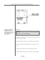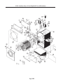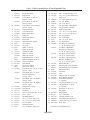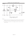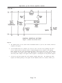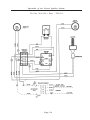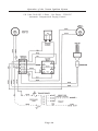
1
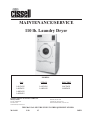
MANUFACTURING COMPANY
MAINTENANCE/SERVICE
110 lb. Laundry Dryer
MODELS
GAS
L44CD42G
L44FD42G
L44KD42G
L44RD42G
STEAM
ELECTRIC
L44CD42S
L44KD42S
L44CD42E
L44KD42E
CISSELL MANUFACTURING COMPANY
HEADQUARTERS
831 SOUTH FIRST ST.
P.O. BOX 32270
LOUISVILLE, KY 40232-2270
PHONE: (502) 587-1292
SALES FAX: (502) 585-3625
SERVICE/PARTS FAX: (502) 681-1275
THIS MANUAL MUST BE GIVEN TO THE EQUIPMENT OWNER.
MAN4M
9/98
1C
D0521
IMPORTANT NOTICES—PLEASE READ
For optimum efficiency and safety, we recommend that you read the Manual before operating the equipment. Store this manual in a
file or binder and keep for future reference.
WARNING: For your safety, the information in this manual must be followed to minimize
the risk of fire or explosion or to prevent property damage, personal injury, or loss of life.
- Do not store or use gasoline or other flammable liquids or vapors in the vicinity of this or
any other appliance.
- WHAT TO DO IF YOU SMELL GAS
•
•
•
•
•
Do not try to light any appliances.
Do not touch any electrical switch; do not use any phone in your building.
Clear the room, building, or area of all occupants.
Immediately call your gas supplier from a neighbor's phone. Follow the gas supplier's
instructions.
If you cannot reach the gas supplier, call the fire department.
Installation and service must be performed by a qualified installer, service agency or the gas
supplier.
WARNING: In the event the user smells gas odor, instructions on what to do must be posted in a
prominent location. This information can be obtained from the local gas supplier.
WARNING: Wear Safety Shoes to prevent injuries.
WARNING: Purchaser must post the following notice in a prominent location:
FOR YOUR SAFETY
Do not store or use gasoline or other flammable vapors
and liquids in the vicinity of this or any other appliance.
WARNING: A clothes dryer produces combustible lint and should be exhausted outside the
building. The dryer and the area around the dryer should be kept free of lint.
WARNING: Be safe, before servicing machine, the main power should be shut off.
Page 2M
WARNING: To avoid fire hazard, do not dry articles containing foam rubber or similar texture materials.
Do not put into this dryer flammable items such as baby bed mattresses, throw rugs,undergarments
(brassieres, etc.) and other items which use rubber as padding or backing. Rubber easily oxidizes causing
excessive heat and possible fire. These items should be air dried.
WARNING: Synthetic solvent fumes from drycleaning machines create acids when drawn through the
dryer. These fumes cause rusting of painted parts, pitting of bright or plated parts, and completely
removes the zinc from galvanized parts, such as the tumbler basket. If drycleaning machines are in the
same area as the tumbler, the tumbler's make-up air must come from a source free of solvent fumes.
WARNING: Do not operate without guards in place.
WARNING: Check the lint trap often and clean as needed but at least a minimum of once per day.
WARNING: Alterations to equipment may not be carried out without consulting with the factory and
only by a qualified engineer or technician. Only Manufacturer’s parts may be used.
WARNING: Remove clothes from dryer as soon as it stops. This keeps wrinkles from setting in and
reduces the possibility of spontaneous combustion.
WARNING: Be Safe - shut main electrical power and gas supply off externally before attempting
service.
WARNING: Never use drycleaning solvents, gasoline, kerosene, or other flammable liquids in the dryer.
FIRE AND EXPLOSION WILL OCCUR. NEVER PUT FABRICS TREATED WITH THESE LIQUIDS
INTO THE DRYER. NEVER USE THESE LIQUIDS NEAR THE DRYER..
WARNING: Do not place items exposed to cooking oils in your dryer. Items contaminated with cooking
oils may contribute to a chemical reaction that could cause a load to catch fire.
WARNING: Never let children play near or operate the dryer. Serious injury could occur if a child
should crawl inside and the dryer is turned on.
WARNING: Never tumble fiberglass materials in the dryer unless the labels say they are machine
dryable. Glass fibers break and can remain in the dryer. These fibers cause skin irritation if they
become mixed with other fabrics.
WARNING: Before operating gas ignition system - purge air from natural gas or propane gas lines
per manufacturer’s instructions.
Page 3M
CISSELL DRYER WARRANTY
The Cissell Manufacturing Company (Cissell) warrants all new equipment (and the original parts thereof) to be free from
defects in material or workmanship for a period of two (2) years from the date of sale thereof to an original purchaser for
use, except as hereinafter provided. With respect to non-durable parts normally requiring replacement in less than two (2)
years due to normal wear and tear, and with respect to all new repair or replacement parts for Cissell equipment for which
the two (2) year warranty period has expired, or for all new repair or replacement parts for equipment other than Cissell
equipment, the warranty period is limited to ninety (90) days from date of sale. The warranty period on each new replacement
part furnished by Cissell in fulfillment of the warranty on new equipment or parts shall be for the unexpired portion of the
original warranty period on the part replaced.
With respect to electric motors, coin meters and other accessories furnished with the new equipment, but not manufactured
by Cissell, the warranty is limited to that provided by the respective manufacturer.
Cissell’s total liability arising out of the manufacture and sale of new equipment and parts, whether under the warranty or
caused by Cissell’s negligence or otherwise, shall be limited to Cissell repairing or replacing, at its option, any defective
equipment or part returned f.o.b. Cissell’s factory, transportation prepaid, within the applicable warranty period and found
by Cissell to have been defective, and in no event shall Cissell be liable for damages of any kind, whether for any injury to
persons or property or for any special or consequential damages. The liability of Cissell does not include furnishing (or
paying for) any labor such as that required to service, remove or install; to diagnose troubles; to adjust, remove or replace
defective equipment or a part; nor does it include any responsibility for transportation expense which is involved therein.
The warranty of Cissell is contingent upon installation and use of its equipment under normal operating conditions. The
warranty is void on equipment or parts; that have been subjected to misuse, accident, or negligent damage; operated under
loads, pressures, speeds, electrical connections, plumbing, or conditions other than those specified by Cissell; operated
or repaired with other than genuine Cissell replacement parts; damaged by fire, flood, vandalism, or such other causes
beyond the control of Cissell; altered or repaired in any way that effects the reliability or detracts from its performance,
or; which have had the identification plate, or serial number, altered, defaced, or removed.
No defective equipment or part may be returned to Cissell for repair or replacement without prior written authorization
from Cissell. Charges for unauthorized repairs will not be accepted or paid by Cissell.
CISSELL MAKES NO OTHER EXPRESS OR IMPLIED WARRANTY, STATUTORY OR OTHERWISE, CONCERNING
THE EQUIPMENT OR PARTS INCLUDING, WITHOUT LIMITATION, A WARRANTY OF FITNESS FOR A PARTICULAR
PURPOSE, OR A WARRANTY OF MERCHANTABILITY. THE WARRANTIES GIVEN ABOVE ARE EXPRESSLY IN
LIEU OF ALL OTHER WARRANTIES, EXPRESS OR IMPLIED. CISSELL NEITHER ASSUMES, NOR AUTHORIZES
ANY PERSON TO ASSUME FOR IT, ANY OTHER WARRANTY OR LIABILITY IN CONNECTION WITH THE
MANUFACTURE, USE OR SALE OF ITS EQUIPMENT OR PARTS.
For warranty service, contact the Distributor from whom the Cissell equipment or part was purchased. If the Distributor
cannot be reached, contact Cissell.
IDENTIFICATION NAMEPLATE
The Identification Nameplate is located on the rear wall of the dryer. It contains the dryer serial number, product number, model
number, electrical specifications and other important data that may be needed when servicing and ordering parts, wiring diagrams,
etc. Do not remove this nameplate.
Page 4M
TABLE OF CONTENTS
110 LB. LAUNDRY DRYER
MAINTENANCE/SERVICE MANUAL
PAGE
Model Numbers & Company Address .............................................................................. 1M
Important Notices ...................................................................................................... 2M-3M
Dryer Warranty ................................................................................................................ 4M
Table of Contents ............................................................................................................. 5M
Warnings, Cautionary Notes and Symbols................................................................. 6M-7M
Direct Spark Ignition System ..................................................................................... 8M-9M
General Maintenance............................................................................................. 10M-11M
Burner Air Inlet Shutters Adjustment..................................................................... 12M-13M
Basket Alignment .................................................................................................. 14M-15M
Shimming the Basket and Spider Assembly.................................................................... 16M
Air Switch Adjustment ................................................................................................... 17M
Dryers with Reversing Control Timer ................................................................... 18M-19M
Large Gear Reducer Maintenance .................................................................................. 20M
Front Panel and Door Assembly..................................................................................... 21M
Dryer - Front View................................................................................................ 22M-23M
Double Motor Model ............................................................................................ 24M-25M
Duct Work Assembly ..................................................................................................... 26M
Basket and Sensor Assembly.......................................................................................... 27M
Temperature Assembly................................................................................................... 28M
Fan Motor Mount Assembly ........................................................................................... 29M
Air Switch and Thermostat Assembly ............................................................................ 30M
Large Gear Reducer with Bronze Teeth ......................................................................... 31M
Non-Reversing Control Panel Assembly ........................................................................ 32M
Permanent Press Control Panel Assembly ...................................................................... 33M
Control Panel and Access Door Assembly..................................................................... 34M
Reversing Control Box Assembly .................................................................................. 35M
Gas Heating Unit ................................................................................................... 36M-39M
Steam Bonnet......................................................................................................... 40M-41M
Electric Heating Unit ............................................................................................. 42M-43M
Ordering Overload Heaters for Overload Relays .......................................................... 44M
Page 5M
SYMBOLS
The following symbols are used in this manual and/or on the machine. The
numbers between () refer to the numbers on the machine surveys.
Symbol
Description
NOTE!
Hot! Do Not Touch
Heiß! Nicht Beruhren
Haute temperature! Ne pas
toucher
Caliente! no tocar
dangerous voltage
tension dangereuse
Gefährliche elektrische
Spannung
tension peligrosa
on
marche
Ein
conectado
off
arrêt
Aus
desconectado
start
demarrage
Start
arranque de un movimiento
emission of heat in general
êmission de chaleur en
general
Warmeabgabe allgemein
emisión de calor
cooling
refroidissement
Kühlen
enfriamiento
Page 6M
Part/Measurement
SYMBOLS
Symbol
Description
rotation in two directions
rotation dans les deux sens
Drehbewigung in zwei Richtungen
movimiento rotativo en los dos
sentidos
direction of rotation
sens de mouvement continu de rotation
Drehbewegung in Pfeilrichtung
movimiento giratorio o rotatorio
en el sentido de la flecha
End of Cycle
caution
attention
Achtung
atencion; precaucion
Page 7M
Part/Measurement
Operation of the Norton Ignition System
OPERATION OF THE
NORTON IGNITION
SYSTEM
Power to the ignition system is 120 volts. It is rated voltage or on higher
voltage machines the 120 volts is from a transformer. The ignition system is
powered through a timer or coin meter and a thermostat which calls for heat.
The two gas valves are plumbed into a single gas line and both must open
before the gas can flow into the burners.
The following diagrams are line to line schematics of the ignition system.
The numbers 4, 7, 3, 9, and letters A and B are terminals on the ignition relay.
FIGURE 1
NORTON IGNITION SYSTEM
Figure 1 (Start of Cycle)
Step #1
a.
The Safety Gas Valve is connected across the lines and opens immediately as soon as a need for
heat is indicated by the thermostat.
b.
The Ignition Relay Coil is energized through the normally closed (NC) contacts of the Radiant
Sensor and the NC contacts of the relay. NOTE: Figure 1 shows the electrical circuit of the
relay just before it is energized. Figure 2 shows the circuit a moment later.
c.
The igniter is energized through the NC contacts of the Radiant Sensor.
d.
The Operating Gas Valve is connected such that the same 120 volts is applied to both sides of
the Gas Valve and the valve stays closed.
Page 8M
Operation of the Norton Ignition System
FIGURE 2
NORTON IGNITION SYSTEM
Figure 2 (Start of Cycle)
Step #2
a.
The Ignition Relay closes now and the Relay Coil stays energized by being powered through the
normally open (NO) contacts of the Ignition Relay which close before the NC contacts open.
b.
The operating gas valve still has the 120 volts applied to both sides of the gas valve and the
valve stays closed.
Page 9M
Operation of the Norton Ignition System
FIGURE 3
NORTON IGNITION SYSTEM
Figure 3 (About 20 Seconds Later)
Step #3
a.
The Ignition glows red hot, which causes the Radiant Sensor to open its NC Contacts, which deenergizes the Igniter.
b.
As the Radiant Sensor NC Contacts open, the 120 volt to one side of the operating Gas Valve
Coil is removed and an electrical circuit is formed through the NO Contacts of the Ignition
Relay, through the Gas Valve and through the Igniter, and the Gas Valve opens. The relatively
low resistance of the Igniter allows nearby full voltage to be applied to the operating Gas Valve
and nearby zero voltage to the Igniter and the Igniter is de-energized for all practical purposes.
c.
As the raw gas flows against the red hot Igniter, ignition takes place. The radiant gas flame
replaces the radiant glowing of the Igniter and the Radiant Sensor NC Contacts remain open.
Page 10M
Operation of the Norton Ignition System
IGNITION OPERATION
The flame will burn until the thermostat opens the circuit or until the time on
the timer or coin meter expires.
The following summarizes the ignition operation:
•
Start machine drying cycle.
•
Carbide igniter will get red hot.
•
Then, gas valve will open.
•
The gas burners are ignited by the carbide igniter.
•
Igniter will shut off and burners will remain on during
drying cycle.
•
Opening tumbler door will cause gas to extinguish. Shut
door and gas will not light until flame sensor cools and
normal ignition cycle begins.
NOTE
NOTE
Push “start” switch after door is shut.
•
SAFETY FEATURES
If gas does not light, then the sensor will cool down and
restart the ignition cycle.
SAFETY FEATURES
Power Interruptions During Burning of the Gas
Both gas valves are de-energized and the gas is shut off. The Ignition Relay is
also de-energized and returns the contacts to the NO and NC positions. Even
with resumption of power, the operating gas valve stays closed until the NC
contacts of the Radiant Sensor close (about 30 seconds from time of power
interruption). A normal ignition cycle begins at this time.
Burner Doesn’t Light Because of Low Voltage or Low Gas Pressure
The operating gas valve will be energized for about 30 seconds and then the
NC contacts of the Radiant Sensor will be closed. 120 volts is applied to both
sides of the operating gas valve and it closes to shut off the gas. A normal
ignition cycle begins at this time.
Page 11M
Operation of the Norton Ignition System
120 Volts; 50/60 HZ; 1 Phase - TWL1512
Page 12M
Operation of the Norton Ignition System
120 Volts; 50/60 HZ; 1 Phase - Gas Dryers - TWL1587
Automatic Computerized Drying Control
Page 13M
Operation of the Norton Ignition System
TEST PROCEDURE
INSTRUCTIONS FOR
DIRECT IGNITION
SYSTEM OPERATION
TEST PROCEDURE
1.
If igniter does not glow red, disconnect and test with
separate 120V. Replace if it does not glow red. If it is
damaged or cracked, replace.
2.
Check wiring of ignition system parts per wiring diagram.
3.
Gas valves must be open (click) when dryer is energized.
Burners will ignite after 12 to 25 seconds.
4.
After flame is burning, Igniter will go out. If both gas
valves do not open, then replace.
5.
If Igniter does not go out, then replace Radiant Sensor. If
the Radiant Sensor glass is broken, replace it.
6.
Open and close dryer loading door after gas has started
burning. When door is closed, gas should not flow until
radiant sensor has cooled and Igniter recycles.
INSTRUCTIONS FOR DIRECT IGNITION SYSTEM
OPERATION
1.
Open manual gas valve; handle should be parallel with gas
line.
2.
Start machine drying cycle. The igniter will glow red hot;
the gas valves will open and the burners will ignite.
3.
The igniter will shut off and the burners will continue
burning during heat cycle.
4.
Opening the tumbler loading door will cause the gas to
extinguish. Shut the door and the gas will not flow until
the flame sensor has cooled. Push the “start” button to
begin cycle after door is closed. If ignition fails, wait for five
minutes to restart.
5.
To shut off dryer, close the manual gas valve. The handle
should be at a right angle to the gas line. Turn off the main
electrical supply switch.
CAUTION
CAUTION
Check igniters with 120V before installing on dryer.
Page 14M
Troubleshooting
TROUBLE ANALYSIS
FOR ENERGY SAVER
DRYERS AND THE
NORTON IGNITION
SYSTEM
EXHAUST PIPE SIZE
DRYER INLET AIR
Trouble analysis for Energy Saver Dryers and the Norton
Ignition System.
CAUTION
Problems with the Norton Ignition System can also be the result
of the following:
1. Exhaust air flow restriction. Exhaust pipe size must be larger
than the exhaust opening. Refer to chart in manual.
2. Dryer inlet air is a MUST for each unit. It must be 4 to 6 times
the combined areas of the dryer exhaust outlet. Refer to chart in
manual.
DRYER PANELS
3. All dryer panels must be in place and on machine for proper
operation.
GAS PRESSURE
4. Gas pressure must be 7-9 1/2 inches WC for natural gas and 11
inches WC for propane or butane (bottled) gases.
5. Refer to chart for correct gas pipe sizes and lengths. The 3/4 inch
gas pipe must be the minimum gas supply pipe for the dryer and
over 50 ft., 1 inch pipe size.
MAIN BURNER ORIFICE
SIZE
6. Main burner orifices must be correct size. They are calculated
with the following information:
a. Your locality heating value of gas, BTU/cu. ft.
b. Local specific gravity of gas.
c. Gas manifold pressure inches of WC.
1)
3.5 inches WC pressure for natural gas.
2)
11 inches WC pressure for propane or butane gases.
d. Gas input rate per each burner orifice.
Page 15M
Troubleshooting
TROUBLE ANALYSIS
FOR ENERGY SAVER
DRYERS AND THE
NORTON IGNITION
SYSTEM (continued)
NOTE
7. Voltage must be identical to what is on the Electrical Rating
Plate. Prevent low voltage; it causes longer drying operation.
8. Back Draft Damper must swing full open to prevent air flow
restrictions. (Check for full open operation every 6 months.)
Non-operative or erratic operation of exhaust dampers will
cause air flow switches to shut off gas and will result in
longer drying time.
NOTE
The above should be checked and corrected
before attempting to troubleshoot the Norton
Ignition System.
Page 16M
Maintenance—General
MAINTENANCE
MAINTENANCE
1.
CLEAN LINT TRAP DAILY. Remove lint before starting day’s
operation. A clean lint trap will increase the efficiency of the dryer, as
the moisture-laden air will be exhausted more quickly.
2.
CLEAN BASKET AND SWEEP SHEETS. Clean periodically and/or
as often as required. The basket and sweep sheets are easily accessible
by removing the front panel of the dryer.
3.
GEAR REDUCER. Maintain the correct oil level. See separate page
on Gear Reducer Operation and Maintenance, for detailed information.
4.
PULLEYS AND BELTS. Keep belts clean. Oil and dirt will shorten
the useful life of the belt. Never allow a belt to run against the belt
guard. Check periodically for alignment. Pulley shafts must be parallel
and the grooves must be aligned. Check and re-tighten pulley set
screws periodically. Check belt tension periodically. Lower motor to
increase tension by adjusting the nuts fastening the motor plate to the
rod connected to the Gear Reducer.
5.
ELECTRIC MOTORS. Keep motors clean and dry. Motors having
ball bearings are packed with sufficient grease for approximately five
years of normal operation. After five years, the bearings and housing
should be cleaned thoroughly. Repack each bearing and the cavity in
back of the bearing on-third full with Chevron Grease No. SR1-2.
Motors having wool packed sleeve bearings are oiled at the
factory for one year of normal operation. After one year, add annually
one-half teaspoon of electric motor oil or S.A.E.#10 to each bearing.
For 24 hour per day operation, add one teaspoon of oil annually.
If motors overheat, check voltage and wiring. Low voltage,
inadequate wiring, and loose connections are the main cause of motor
failure.
Page 17M
Maintenance—General
MAINTENANCE (Cont’d)
6.
STEAM HEATING UNITS. Keep steam coils clean. Check
periodically and clean often, as required. Remove lint and dirt build-up
from fins. Dirty fins decrease the efficiency of steam heated units.
7.
GAS BURNERS. Keep burners clean. Check periodically and clean
often.
8.
EXHAUST SYSTEM. Periodically check and clean.
9.
CLEAN OUT PANEL. (Energy Saver Gas Models) Remove this
panel, located on the heating unit, and clean the inside area of lint and
dirt on a regular basis.
10.
DRYER AREA. Keep dryer area clean and free from combustible
materials, gasoline and other flammable vapors and liquids.
11.
MAKE-UP AIR. Do not obstruct the flow of combustion (make-up)
air and ventilating air.
12.
GAS PRESSURE. Periodically check gas pressure.
13.
DRYER VOLTAGE. Periodically check dryer voltage per dryer
Rating Plate.
Page 18M
Burner Air Inlet Shutters Adjustment (with Illustration)
BURNER AIR INLET
SHUTTERS ADJUSTMENT
Burner Air Inlet
Shutters Adjustment
Type of Gas
Natural Gas
Liquid Petroleum
Manufactured Gas
1/2 Open
1/4 Open
1/16 Open
Air Shutters Adjustment
Proper Method: Close air shutters to yellow tip, then open air
shutters to blue flame tip. Orange tips are impurities in the air such
as lint, dust, etc.
Burners Air Inlet Shutters are correctly adjusted when flame is
primarily blue.
CORRECT
Page 19M
Burner Air Inlet Shutters Adjustment (with Illustration)
NEED TO PROVIDE
CORRECT AIRFLOW
THROUGH THE DRYER
Need to Provide Correct Airflow Through the Dryer
This flame pattern indicates the Burner Air Inlet Shutters are
correctly adjusted, but air through the dryer is insufficient. This
condition indicates excessive lint in the lint compartment, lack of
make-up air in the room, restricted exhaust duct, or a vacuum in the
room caused by an exhaust fan.
WRONG
Page 20M
Basket Alignment for 110 lb. Dryers (Illustrations)
Page 21M
Basket Alignment for 110 lb. Dryers
INSTRUCTIONS
INSTRUCTIONS FOR
ALIGNING BASKETS ON
1. Loosen bolts number one (1) through five (5).
CISSELL 110 LB. DRYERS
2. Place pin “A” in position shown in figures 1 and 2.
3. Check pins “B” at position shown in figures 1 and 2 for
equal clearance.
4. If pin “B” clearance is unequal, adjust at nut #6.
5. When clearance at pin “B” is correct, tighten bolts #1 in the
following order, as viewed from rear of dryer, top right,
bottom left, top left and bottom right.
6. Tighten bolts #5 until flush against back of dryer. Tighten
lock nut #4 to secure bolt #5 in position.
7. Tighten bolts #2 and #3.
8. Remove pin “A” and check for proper clearance at points
“A” and “B”. If clearance is incorrect, repeat the above
steps.
NOTE
Use short sections of round steel rod for pins or drill bits may
be used in place of round rod.
Page 22M
Shimming the Basket and Spider Assembly
This procedure is normally necessary when replacing either the
INSTRUCTIONS FOR
SHIMMING THE BASKET basket or the spider assembly on any Cissell dryer. The alignment of
AND SPIDER ASSEMBLY these two parts is crucial in assuring a true running basket.
A. Align the basket as per instructions on the previous page.
B. Rotate the basket to determine where the most out-of-round
point is (where the basket scrapes or comes closest to
scraping the sweep sheet).
C. Mark this position and the nearest rib to this position. If it is
between two ribs, both ribs may need to be shimmed.
D. Remove the basket from the dryer (do not loosen the
alignment bolts).
E. With the basket on the floor (spider up), loosen the cap
screws and tie rod nuts enough to insert one or two shims
between the spider leg and the basket at the marked position.
With shims in place, tighten the screws and nuts.
F. Install spider and basket assembly and check again.
G. If basket is still out-of-round, start at Step B and repeat
procedure.
H. When shimming is completed, re-align basket.
Page 23M
Air Switch Adjustment
AIR SWITCH
ADJUSTMENT
1. Shut off current; disconnect leads and remove air switch.
2. Lay air switch assembly on flat surface. Adjust air blade at
“A” (figure 1) so that air blade lays flat and surface “B” is
parallel to the flat surface.
3. Place 3/8” x 5/8” spacer bar or equivalent “C” (figure 2)
under air blade in position shown; hold switch mounting
bracket firmly and adjust switch actuator “D” with needle
nose pliers at “E” by twisting actuator right or left,
whichever is needed, so that switch closes when end of air
blade engages bar “C”.
4. Maximum opening of air switch must be no greater than 3/4”
(figure 3). Bend tab “F” in or out to maintain this dimension.
5. Re-install air switch assembly on rear of dryer.
6. Re-check operation of air blade. Switch must close before
air blade engages face of opening and re-open before stop
“F” engages.
Page 24M
Dryers with Reversing Control Timer
INSTRUCTIONS FOR
DRYERS WITH
REVERSING CONTROL
TIMER
Instructions
In operation, coasting of basket increases, making it necessary to
readjust reversing timer.
CAUTION
Failure to do this will cause the thermal overload units for the
basket to cut-out unnecessarily and probably damage the
gear reducer.
Adjustment of Reversing Timer Dwell Time
CAUTION
Dryer power supply must be shut off before adjusting timer.
The dwell time is the time from when the motor turns “off”, to when
it turns “on” again in the opposite direction.
Turning the dwell adjustment knob counter-clockwise increases the
dwell time and turning it clockwise decreases the dwell time.
Recommended dwell time for the basket to stop completely is 5 to 7
seconds. Minimum basket stopping time is
4 seconds.
NOTE
Select non-reversing or reversing before starting dryer.
NOTE
Fan rotates counter-clockwise as viewed from back end of
motor. See arrow on motor support. to change rotation,
reverse power leads L1 and L2.
Page 25M
Dryers with Reversing Control (Furnas Timer Illustration)
INSTRUCTIONS FOR
DRYERS WITHOUT
REVERSING CONTROL
FAN AND BASKET
ROTATION
Instructions
NOTE
Fan rotates counter-clockwise as viewed from back end of
motor. See arrow on motor support.
Basket rotates counter-clockwise as viewed from back end of motor.
See arrow on motor support.
Basket rotates counter-clockwise as viewed from front of tumbler.
To change rotation of both fan and basket, reverse power leads L1
and L2.
To change rotation of fan only, reverse motor leads F1 and F2.
To change rotation of basket only, reverse motor leads B1 and B2.
Page 26M
Large Gear Reducer Maintenance
LARGE GEAR REDUCER
MAINTENANCE
LARGE GEAR REDUCER MAINTENANCE
Before placing the dryer in operation, check the oil level. If the
oil level is correct, it can be seen through the sight glass on the right
hand side of the gear reducer (facing rear).
If oil must be added, remove the pop-off valve at the top of the gear
reducer and add as needed.
CHANGE OIL ONCE EVERY 6 MONTHS.
Page 27M
110 lb. Laundry Dryer (Front Exploded View) (Illustration)
Page 28M
Parts—110 lb. Laundry Dryer (Front Exploded View)
1 TU8013
2 TU5739
3 TU8095
TU9847
3A TU8099
4
5
6
8
9
10
11
12
13
14
15
16
17
18
19
20
TU5674
TU7159
TU9866
K118
TU2486
TU2477
TU5337
F646
TU5290
K109
K348
TU5397
TU6469
TU9856
K421
K383
TU10345
TU7473
K368
K121
TU7802
TU5934
TU9895
TU9896
21
22
23
24
25
26
27
28
29
30
31
TU6030
TU1979H
TU1770
TU1771
TU3219
TU2373
TU7733
TU3479
FG343
FG345
P104
Cissell Nameplate
Support Rod
Access Door “C” and “F”
(Specify Color)
Access Door “K” and “R”
(Specify Color)
Access Door “Static Steamer”
(Specify Color)
Control Box Brace
Left Control Box
Right Control Box
Gasket Set
Thermostat Bracket
Thermostat
Thermostat Bulb Support
5/16” Clamp
Felt Seal
Spider “C” and “F”
Spider “K” and “R”
Outside Rib Plate
Basket “C” and “F”
Basket “K” and “R”
Basket and Spider “C” & “F”
Basket and Spider “K” & “R”
Lint Screen Hood
Door Handle
Lint Screen ONLY
Wire Frame ONLY
Front Panel Asm. “R” & “F” Gas *
(specify color)
Front Panel Asm. “C” & “K”
Electric and Steam *
(specify color)
Front Panel Asm. “K” Model *
(specify color)
Front Panel Asm. “R” Model *
(specify color)
Temperature Control *
Door Switch
Insulation
#6 Twin Speed Nut (Pkg. of 12)
#6 x 1” Screw
Mounting Bracket
#8 x 1/2” Screw (Pkg. of 6)
#10 - 32 x 7/16” Truss Screw
Screw Fastener
Retaining Washer
1/4” Cut Washer (Pkg. of 6)
32 TU2842
33 TU3246
34
35
36
37
38
39
40
41
42
43
44
45
VSB134
IB140
TU6854
LB74
TU7848
TU3801
TU2662
TU2664
OP251
TU5801
F557
FB187
TU5645
TU6257
TU7803
TU7804
46 TU9975
47 TU490
TU491
48 K169
49 TU6025
50 TU3811
51 TU6159
52 TU6808
53 TU10673
56 TU7691
57 TU7690
58 TU7692
59
60
61
62
63
64
TU9209
RC349
TU7719
TU8036
TU6160
TU11568
#10 - 32 Hex Nut (Pkg. of 6)
3/8” - 16 x 1” Hex Head Screw
(Pkg. of 6)
3/8” Lockwasher (Pkg. of 6)
3/8” Cut Washer
#14 x 3/4” Screw
#14 Speed Nut without Barbs
#14 Speed Nut with Barbs
Push On Speed Nut
1/2” - 20 x 1 1/2” Cap Screw
5/8” - 18 x 1 1/2” Cap Screw
1/2” Lockwasher
5/8” Lockwasher
#10 - 24 x 3/8” Screw
#10 Lockwasher
Lint Door (no Insulation)
“C” & “K” (specify color)
Lint Door with Handles,
Hardware (no Insulation)
“C” & “K” (specify color)
Lint Door (with Insulation)
“R” & “F” (specify color)
Lint Door (with Insulation),
Handles, and Hardware,
“R” & “F” (specify color)
Basket Shaft Key
Thermostat Knob (Fahrenheit)
Thermostat Knob (Centigrade)
Handle Assembly
Cam Stop
Cam
Support Clips (2 required)
Reset Button Assembly
Front Panel Insulation
(4 required)
Left Side Insulation “F” & “R”
Side Insulation “F” & “R”
(9 required)
Insulation “F” “R” & “C”
Gas Model
Snap Bushing
1/4" Lockwasher
Conduit Channel Cover
Left Control Box Shield “C”
Lint Screen Clip (2 required)
Door Trim
* See Page 56 for Exploded View
Page 29M
110 lb. Dryer (Double Motor Models) (Illustration)
MODELS:
L44KD42
L44CD42
L44RD42
L44FG42
GAS, STEAM or
ELECTRIC
Page 30M
Parts—110 lb. Laundry Dryer (Double Motor Models)
1 TU5507
Blanking Plate “C” Model
Steam Dryer
2 TU4967
5/16” - 18 x 1/2” Allen Set Screw
3 TU8206
Air Switch**
4 AT304
5/16” - 18 x 1” Set Screw
5 TU3806
Gear Sheave
6 TU3807
Sheave Bushing
7 TU5668
Outside Belt Guard
8 TU2363
“V” Belt 5L500
9 TU2832
Motor Sheave 60 Cy.
TU6081
Motor Sheave 50 Cy.
10 TU2833
Sheave Bushing
11 TU9615
Belt Guard Welded Asm.
12 TU470
Large Hex Nut (2 required)
13 TU6633
2-3/4” O.D. x 1- 13/32”
I.D. x 3/4” Thick Washer
14 TM200
Gear Reducer**
15 TU5328
Belt Adjusting Rod
16 TU4626
Basket Motor Mount Asm.
*17 TU5658
Motor and Fan Mount (60 Cycle)
18 TU2473
Self-Sticking Gaskets
(4 required)
*19 TU403
Fan Wheel (60 Cycle)
20 TU4791
90 Degree Angle Connector
21 TU2372
Snap Bushing (not used on
Steam Dryer)
22 CFB2800
1/2" Greenfield Cable
(specify 28”)
23 TU6026
Top Motor Conduit
24 TU6027
Back Motor Conduit
25 TU6028
Power Lead Conduit
Use TU8215 Conduit on Electric Dryers ONLY
26 500300644 Junction Box
27 TU7130
1/2” Straight Connector
28 TU7131
3/4” Straight Connector
29 SB170
Junction Box Cover
30 TU5827
Jacket Welded Assembly
31 TU4684
Key
32 TU7733
#8 x 1/2” Self Drinning Screw
(Pkg. of 6)
33 RC347
1/2” - 13 x 1 1/4” Hex Head Cap
34 TU2831
1/2” Split Lockwasher (Pkg. of 6)
35 TU1851
1/2” Flat Washer
36 TU2195
1/2” - 13 x 1 3/4” Hex Head
Cap Screw (Pkg. of 6)
37 TU455
38 TU3575
39 TU5312
40 TU4787
41 TU5439
42 TU2814
43
44
45
47
C249
TU2831
TU108
CFB0650
48 TU2846
49 TU2847
50 TU4934
51 FB189
52 TU7517
TU10732
53 TU8194
54 TU8550
55 TU2490
56 TU8599
57 TU8709
58 M270
59 TU3400
60 TU8629
61 K377
62 TU8738
63 TU8582
64 TU2490
65 FB187
66 CFB3000
Cam Adjustment Nut
7/8” Internal Tooth Lockwasher
3/8” - 16 x 3” Square Head
Set Screw
3/8” - 16 Hex Nut (Pkg. of 6)
5/16” - 18 x 3/4” Hex Head
Cap Screw (Pkg. of 6)
5/16” Split Lockwasher
(Pkg. of 6)
5/16” - 18 Hex Nut (Pkg. of 6)
3/8” Split Lockwasher (Pkg. of 6)
Felt Seal
1/2” Greenfield Cable
(specify 6 1/2”)
1/4” Split Lockwasher (Pkg. of 6)
1/4” Flat Washer (Pkg. of 6)
1/4” - 20 x 7/16” Hex Nut
(Pkg. of 6)
1/4” - 20 x 1” Hex Head Screw
Basket Shaft Cover
Prompter Housing Assembly**
Air Switch Box Cover
Air Switch Box
Plug Button
Relay (Igniter)
Relay Bracket
Internal Tooth Lockwasher
(Pkg. of 6)
Hex Nut #6 - 32 x 15/16”
(Pkg. of 6)
Terminal Board (Igniter)
Transformer with Fuse
(208, 220, or 240V Primary
120V Secondary)
6 Amp Fuse
Ingition Control Box
Conduit Plate
Plug Button 7/8”
#10 Lockwasher (Pkg. of 6)
1/2” Greenfield Cable - 30”
CAUTION
Grease to be applied to all bearing shafts, #42-0326015 grease Lubriplate #310, 1 lb. cans OR 14 1/2
ounce tubes - Lubriplate No. 930-2, multi-purpose
grease #10098.
* For 50 Cy. Motor Mount Assembly
** See separate page for parts breakdown
Page 31M
Front Panel and Door Assembly (Illustration)
TU5934
TU7802
TU9895
TU9896
1 K105
K105C
2
3
4
5
6
7
8
TU1692
TU5503
TUA2319H
TU5500
TU2236
TU5288
TU7801*
TU6047
9
10
11
12
13
TU2641
TU5458
TU2105
TU2582
PIF172
Electric, Steam “C”, “K” Model (specify color)
Gas “C”, “F” Model
“K” Model
“R” Model
Door Glass 15 - 3/4” (plain)
Door Glass 15 - 3/4”
(with logo)
Door Glass Gasket
Door Latch Spacer (pkg. 6)
Door Latch with Keeper
Door (specify color)
Hinge Post
Door Seal
Front Panel “F” and “R” Model
(specify color)
Front Panel “C” and “K”
Model (specify color)
Thermometer Gasket
Temperature Label
Actuator Spring
Actuator
Hinge Post Bearing
(2 required)
14
15
16
17
M262
AT368
TU3266
TU2836
18 TU3212
19 TU3209
20 TU4839
21
22
23
24
TU4840
TU2687
TU3785
TU2686
25 TU7855
26 TU7858
27 RC347
28 TU9894
* Insulation part numbers
#8 - 32 x 3/8” Truss Screw
#8 Split Lockwasher
#10 - 32 Hex Nut (Pkg. of 6)
5/16” - 32 x 3/8” Hex
Head Screw (Pkg. of 6)
5/16” I.T. Lockwasher
#14 x 5/8” Pan Head Screw
(Pkg. of 6)
#10 - 32 x 3/8” Hex
Head Screw (Pkg. of 6)
#10 - 32 Crown Nut (Pkg. of 6)
#8 - 1/2” Phillips Head Screw
#8 Cup Lockwasher
#8 - 32 x 3/8” Phillips
Head Screw
Instruction Nameplate
“Clean Lint Compartment”
Nameplate
1/4” Lockwasher
Plug Button—Prompters
ONLY
Page 32M
110 lb. Duct Work (Illustration)
DUCT WORK
HORIZONTAL OR VERTICAL
1
2
3
4
5
6
7
8
TU8079
TU8081
TU7640
TU8228
TU7624
TU7625
TU7626
TU8594
Duct Elbow
Duct—Long
Duct—Short
Duct Tee
12” Diameter Duct—24” Long
12” Diameter Duct—30” Long
12” Diameter Duct—Elbow
Duct Work Decal (“F” and “K” Models ONLY)
Page 33M
Basket and Sensor Assembly—“K” and “R” Models (Illustration)
1
2
3
4
5
6
7
8
TU9616
TU9618
TU9856
TU9617
AT388
TU9910
TU9949
TU3400
9
10
11
12
13
14
15
16
17
18
19
20
21
22
23
TU9621
K348
TU9854
TU3266
TU9853
TU9660
RC353
TU9944
TU10915
TU10916
TU9628
TU10917
TU7733
M271
Tip
Insulator Washer
Prompter Basket Assembly
Insulator Disc
Terminal Connector
Ext. Tooth Lockwasher
Machine Screw
#6 - 32 Brass Hex Nut
(Pkg. of 6)
Rod Insulator
Prompter Spider Weldment
Sleeve
#8 - 32 Hex Nut (Pkg. of 6)
Conductor Rod
Wiper and Button
Machine Screw
Washer
Wiper Insulator
Wiper Housing
Jumper Wire
Housing Cover
Self Drilling Screw (Pkg. of 6)
Int. Tooth Lockwasher
(Pkg. of 6)
TU10732 consists of Ref. No’s. 19, 21, and 22
Page 34M
Temperature Assembly (Illustration)
TU6030—“C” Model—Consists of Ref. No. 1, 2, 3
TU9718—“K” Model—Consists of Ref. No. 1, 3
1 TU5530
2 TU1980
3 TU3593
TU3816
TU8475
TU11193
TU13213
4 TU490
TU491
5 TU3209
6 TU7848
Mounting Bracket
Thermostat
Thermometer
Lens Replacement (Texas Gage ONLY)
Lens Replacement (Marshaltown Inst. ONLY)
Lens Replacement (Weiss—consult factory)
Lens Replacement (Weiss—consult factory)
Thermostat Knob (Fahrenheit)
Thermostat Knob (Centigrade)
#14 x 5/8” S.M.S. (Pkg. of 6)
#14 Tinnerman Clip
Page 35M
Fan Motor Mount Assembly—50 Hz. Models (Illustration)
TU8826—208 or 440V/50/3
TU6006—240/415V/50/3
TU11609—220/380/50/3
TU10653—200/346/50/3
1 TU6086
2 TU2473
3 TU5659
4
5 TU4706
6 TU1693
7 TU1950
8
9
10
11
12
13
14
15
16
SB138
TU4715
TU2008
TU2009
TU2007
TU3807
TU3393
TU4716
TU4704
50 Cycle Fan with Set Screws
Self Sticking Gaskets
(2 Sets required)
50 Cycle Motor Mount
Motor: Specify Motor
No. and Voltage
Motor Mount Plate
Jack Shaft
Motor Support Rod
(2 required)
Pillow Block (2 required)
Belt Guard Weldment
Sheave 2AK46H
Sheave 2AK39H
H 7/8” Bushing
H 3/4” Bushing
4L280 “V” Belt (2 required)
Belt Guard Cover
5/6” - 24 x 1/4” Hex
Head Screw
17
18
19
20
TU2814
V56
TU4787
TU3246
21
22
23
24
25
26
27
TU4684
OP380
VSB134
IB140
RC344
TU2847
TU7733
28 AT304
29 TU4967
Page 36M
5/16” Split Lockwasher (Pkg. of 6)
5/16” - 24 Hex Nut (Pkg. of 6)
3/8” - 16 Hex Nut (Pkg. of 6)
3/8” - 16 x 1” Hex Head Screw
(Pkg. of 6)
1 1/2” Key
3/8” - 16 x 1 1/2” Hex Head Screw
3/8” Split Lockwasher (Pkg. of 6)
3/8” Flat Washer
1/4” - 20 x 3/4” Hex Head Screw
1/4” Flat Washer (Pkg. of 6)
#8 x 1/2” Self Drilling Screw
(Pkg. of 6)
5/16” - 18 x 1” Set Screw
5/16” - 18 x 1/2” Allen Set Screw
Air Switch Assembly and Thermistor Assembly (Illustrations)
AIR SWITCH ASSEMBLY
TU8206
1
2
3
4
5
6
7
8
F888
TU2463
TU3476
TU1771
TU8155
TU1770
TU8171
TU7733
9 TU3219
“E” Ring
Actuator Arm
Air Switch Decal
#6 Tinnerman Nut (Pkg. of 12)
Air Switch
Insulator
Air Switch Bracket
#8 - 18 x 1/2” Self Drilling Screw
(Pkg. of 6)
#6 x 1” Round Head S.M.S.
THERMISTOR ASSEMBLY
“K” and “R” Models Only
TU12582
1
2
3
4
5
6
7
8
TU9720
LB291
TU2477
TU3624
TU3400
TU11991
AT368
TU3801
Bracket
#6 - 32 x 3/8” Screw
High Limit Thermostat
#6 Machine Screw
#6 Hex Nut (Pkg. of 6)
Thermistor
#8 Lockwasher
Speed Nut
Page 37M
Non-Reversing Control Panel Assembly (Illustration)
TU8723
TU8719
TU8721
TU8718
TU8865
1
2
3
4
5
Non-Reversing
Non-Reversing
Non-Reversing
Non-Reversing
Non-Reversing
TU10579
TU6774
* TU267900
* TU267900
** TU6965
*** TU6963
6
7
8
**** TU8727
TU6959
TU4660
TU4659
TU9804
TU7733
(Pkg. of 6)
Control
Control
Control
Control
Control
Panel
Panel
Panel
Panel
Panel
480/60/3 with 120V Controls
240/415/50/3 with 240V Controls
480/60/3 with 240V Controls
208/240/60/3 with 240V Controls
550/60/3 with 240V Controls
Harness Clamp
Overload Unit
Overload Heater (Fan)
Overload Heater (Basket)
Contactor 120V 60 Hz.
(2 required)
Contactor 208V 60 Hz.
(2 required)
Contactor 240V 50 Hz.
Panel Plate
Transformer 480/240 &
240/120
Transformer 575/240
Transformer 480/120V
#8 - 1/2” Self Drill Screw
9
TU8713
TU8714
9a
SC593
9bSC594Housing-Male
10
TU2793
11
12
RC349
TU3209
13
14
15
LB74
TU10596
TU10597
* To order Overload Heaters, refer to chart.
** TU7281 Contactor Coil ONLY
*** TU7282 Contactor Coil ONLY
**** TU8689 Contactor Coil ONLY
Page 38M
Wiring-Plug Type
(For Dryers without
Transformers)
Wiring-Plug Type (For
Dryers with Transformers)
Housing-Female
1/4” - 20 x 3/4” Hex
Head Screw (Pkg. of 6)
1/4” Int. Tooth Lockwasher
#14 x 5/8” Pan Hd.
Machine Screw (Pkg. of 6)
#14 Speed Nut
Fuse Holder
Fuses
Permanent Press Control Panel Assembly (Illustration)
GAS OR STEAM
TU8730
(60 Hz. 230V) F/208/230-550
TU8731
(60 Hz. 230V) Rev. F/208/230-550
TU8805
(50 Hz. 230V) F/230-415
TU8809
(50 Hz. 230V) Rev. F/230-415
TU8806
(60 Hz. 115V) F/480 Gas ONLY
TU8807
(60 Hz. 115V) Rev. F/480 Gas ONLY
TU8730
(60 Hz. 230V) F/480 Steam ONLY
TU8731
(60 Hz. 230V) Rev. F/480 Steam ONLY
1 TU11950
2 K193
K188
K192
3 TU264
4 TU10579
5 TU2555
6 M454
M102
7 TU7673
TU8154
8 K194
K189
K190
9 M262
10 TU3266
11 TU3805
Control Panel
60 Minute Timer 240/60
60 Minute Timer 120/60
60 Minute Timer 240/50
Toggle Switch
Harness Clamp
Knob Assembly
Amber lamp 240V
Amber Lamp 120V
Permanent Press Nameplate
Permanent Press Nameplate
(Reversing, Non-Reversing)
15 Minute Timer 240/60
15 Minute Timer 120/60
15 Minute Timer 240/50/60
#8 - 32 x 3/8” Truss Head Screw
#8 - 32 Brass Hex Nut (Pkg. of 6)
15/32” - 32 Hex Head Lock Ring
ELECTRIC
TU8879
(60 Hz. 230V) F/208
TU8880
(60 Hz. 230V) F/230-460-550
TU8881
(50 Hz. 230V) F/230-415
TU8882
(60 Hz. 208V) Rev. F/208
TU8883
(60 Hz. 230V) Rev. F/230-460-550
TU8884
(50 Hz. 230V) Rev. F/230-415
12 TU13224
TU13225
13 TU9028
14 AT383
Relay 100-120V 50/60 Hz
Relay 200-240V 50/60 Hz
Push Button Switch
#8 - 32 x 1/2” Truss Head Screw
15 ET208
16 M271
#6 - 32 x 1/4” Pan Head Screw
#8 Internal Tooth Lockwasher
(Pkg. of 6)
(Pkg. of 6)
17 FG147
18
18a
18b
19
20
21
22
23
24
TU8712
SC593
SC594
FB187
TU3209
RC349
LB74
TU7505
TU8279
Page 39M
Toggle Switch (Reversing,
Non-Reversing Controls)
Wiring Harness
Housing - Female
Housing - Male
#10 Lockwasher
#14 x 5/8” P.H.M. Screw (Pkg. of 6)
1/4 I.T. Lockwasher
#14 Speed Nut
Fuseholder (2) Electric ONLY
Fuse (2) Electric ONLY
Control Panel and Access Door Assembly—“K” and “R” Models (Illustration)
110 lb. Dryers—Reversing and Non-Reversing
1 TU3400
2 TU12254
3 TU12105
TU12106
4 TU12195
TU12196
5 TU12842
6 TU12841
7 TU11568
8 TU8013
9 TU3479
10 P104
11 FB187
12 TU2842
13 FG343
14 TU1771
15 TU9524
16 TU6808
17 TU5739
18 TU12863
19 ET235
#6 - 32 Brass Nut (Pkg. of 6)
Spacer
Reversing Control Board
Non-Reversing Control Board
Reversing Panel Label
Non-Reversing Panel Label
Control Panel
Access Door
Trim
Cissell Label
#10 - 32 Truss Head Screw
1/4” Cut Washer (Pkg. of 6)
#10 Lockwasher
#10 - 32 Hex Nut (Pkg. of 6)
Screw Fastener
Twin Clip Nut (Pkg. of 12)
#6 x 5/16” Screw
Reset Button
Support Rod
Fuse - 5 Amp.
Fuse - 3/8 Amp.
Page 40M
Reversing Control Panel Assembly (Illustration)
TU13123
TU13121
TU13164
TU13122
Reversing
Reversing
Reversing
Reversing
1
TU6959
2
TU12874
3
Control
Control
Control
Control
Panel
Panel
Panel
Panel
480/60/3 with 120V Controls
208/240/60/3 with 240V Controls
480/60/3 with 240V Controls
240/415/50/3 with 240V Controls
Control Panel Plate
10
TU10596
Fuse Holder
Electronic Reversing Timer
11
TU10597
Fuse
F540
#6 x 5/8” Sheet Metal Screw
12
**** TU267900
Overload Heater (fan)
4
TU13126
Transformer Mounting Plate
13
**** TU267900
Overload Heater (basket)
5
TU12989
Transformer 120V/24V
14
TU6774
TU12990
Transformer 208-240V/24V
15
RC344
6
TU7733
7
* TU6965
#8 x 1/2” Large Self Drill Screw
(Pkg. of 6)
** TU6963
*** TU8727
8
* TU7252
** TU6964
16
Contactor 208-240V 60 Hz,
*** TU8728
TU2793
TU4660
Transformer 480-240V/240-120V
TU4659
Transformer 575/240V
TU10579
17
Transformer 440-480-575V/120V
SC594
Housing—Male
Housing—Female
Contactor 240V 50 Hz
18
SC593
Rev. Contactor 120V 60 Hz
19
TU10579
Harness Clamp
Rev. Contactor 208V - 240V 60 Hz,
200-220 V 50 Hz
9
1/4” - 20 x 3/4” Large Hex
Head Screw
Contactor 120V 60 Hz
200-220V 50 Hz
Overload Unit
* TU7281
Rev. Contactor 240V 50 Hz
** TU7282
#8 x 3/4” Large Self Drill Screw
Contactor Coil ONLY 120V 60 Hz
Contactor Coil ONLY 208-240V
60 Hz, 200-220V 50 Hz
(Pkg. of 6)
*** TU8689
Contactor Coil ONLY 240V 50 Hz
**** To order Overload Heater, refer to chart
Page 41M
Gas Heating Unit—L44CD42 and L44KD42 (Illustration)
TU11948—Natural Gas Models
TU11949—L.P. Gas Models
Page 42M
Parts—Gas Heating Unit—L44CD42 and L44KD42
1
2
3
4
5
6
7
8
9
10
11
12
13
14
15
16
17
18
19
20
21
22
23
24
25
26
27
28
29
30
31
32
33
34
35
36
37
38
39
40
TU8020
TU11888
TU11887
TU11886
TU7733
TU8759
RC344
TU2846
Rear Shield
Burner Support Top, Right Side
Burner Support Top, Left Side
Burner Support Bottom
#8 x 1/2” Self Drill Screw (Pkg. of 6)
Heat Shield
1/4” - 20 x 3/4” Hex Head Screw
1/4” Split Ring Lockwasher (Pkg. of 6)
PT196
TU4934
TU11646
TU8613
TU8645
TU11899
TU10664
TU11827
TU10692
F875
CFA1600
C170
F876
CFB6800
TU4790
602102180
TU8598
TU11619
TU7881
TU2846
CB36
TU9614
TU2224
TU3539
TU10623
TU8596
TU8605
TU11851
TU4820
M271
TU3416
TU13187
TU13188
TU13373
TU13632
3/4” Pipe Strap
1/4” - 20 Hex Nut (Pkg. of 6)
Bonnet
Ingiter Instruction Plate
“Purge Gas Lines” Plate
Left Side Shield
Burner Holder
Front Burner Support
Front Shield
3/8” Straight Connector
3/8” Cable - 16” Long
3/8” Bushing
3/8” - 90° Connector
1/2” Cable - 68” Long
1/2” Straight Connector
#8 x 1/2” Screw
Radiant Sensor
Igniter Burner with Bracket
Gas Burner
1/4” Lockwasher (Pkg. of 6)
1/4” - 20 x 1/2” Hex Head Screw (Pkg. of 6)
Gas Manifold
1/8” Plug
Burner Orifice (specify Drill Size)
3/4” x 1/2” 90° Elbow
Igniter
Molex Wire Connector
Burner Shield
3/16” x 1/2” Cut Washer
#8 Lockwasher (Pkg. of 6)
#8 x 1 1/4” Screw (Pkg. of 6)
1/2” Combination Gas Valve (Natural Gas)
Kit (Natural Gas to LP Gas)
1/2” Combination Gas Valve (L.P. Gas)
Kit (LP Gas to Natural Gas)
(Above kits do not include orifices)
1/2” x 2” Nipple
41 OP290
Page 43M
Gas Heating Unit—L44FD42 and L44RD42 (Illustration)
TU11960—Natural Gas Models
TU11961—L.P. Gas Models
Page 44M
Parts—Gas Heating Unit—L44FD42 and L44RD42
1
2
3
4
5
6
7
8
9
10
11
12
13
14
15
16
17
18
19
20
21
22
23
24
25
26
27
28
29
30
31
32
33
34
35
36
37
38
TU8156
TU7555
TU12042
TU12043
TU12046
TU7733
TU8577
602102180
TU8613
TU8645
TU11890
TU11886
TU11887
TU8759
TU11874
RC344
TU2846
PT196
TU4934
TU10664
TU11897
F875
CFA1600
C170
F876
CFB6800
TU4790
602102180
TU8598
TU11619
CB36
TU9614
TU2224
TU10946
TU3539
TU7881
OP290
TU13187
TU13373
TU13188
TU13632
39
40
41
42
43
44
45
46
TU10623
TU3416
M271
TU4820
TU11851
TU8605
TU8596
TU7607
Bonnet Enclosure
Enclosure Top
Cover with Clean Out Label
Rear Cover with Clean Out Label
Lower Rear Cover with Label
#8 - 18 x 1/2” Self Drill Screw (Pkg. of 6)
#8 Speed Nut
#8 Sheet Metal Screw
Ignition Instructions Label
“Purge Gas Line” Label
Burner Support Top Right Side
Burner Support Bottom
Burner Support Top Left Side
Heat Shield
Bonnet
1/4” - 20 x 3/4” Hex Screw
1/4” Lockwasher (Pkg. of 6)
Strap
1/4” Hex Nut (Pkg. of 6)
Burner Holder
Front Burner Support
3/8” Straight Connector
3/8” Cable - 16” Long
3/8” Cable Bushing
3/8” Angle Connector
1/2” Cable - 68” Long
1/2” Straight Connector
#8 Sheet Metal Screw (Pkg. of 6)
Radiant Sensor
Ignition Burner with Bracket
1/4” - 20 x 1/2” Hex Screw
Gas Manifold
1/8” Pipe Plug
Manifold Plug
Gas Orifice (specify Drill Size)
Burner
1/2” x 2” Nipple
Gas Valve (Natural Gas)
Gas Valve (L.P. Gas)
Kit (Natural Gas to LP Gas)
Kit (LP Gas to Natural Gas)
(Above kits do not include orifices)
3/4” x 1/2” 90° Elbow
#8 x 1 1/4” Screw (Pkg. of 6)
#8 Lockwasher (Pkg. of 6)
Cut Washer
Burner Shield
Wire Connector
Igniter
Front Lower Cover
Page 45M
TU8134—Steam Bonnet (4 Coil) (Illustration)
1 TU7393
2 TU3209
Top Plate
#14 x 5/8” Sheet Metal Screw
(Pkg. of 6)
3
4
6
7
10
11
TU6458
TU1699
LB74
TU8082
TU2846
TU4934
Air Filter (4 required)
Steam Coil (4 Coil)
#14 Speed Nut
Bonnet Weldment
1/4” Lockwasher (Pkg. of 6)
1/4” - 20 x 7/16” Hex Nut
(Pkg. of 6)
12 TU4605
13 TU4608
3/4” Elbow
3/4” x 2” Nipple
14
15
16
17
18
19
TU4610
TU4600
TU4620
TU4597
TU5914
TU5924
TU6763
TU5939
TU10289
20 390401031
24 FB189
25 TU5726
Page 46M
3/4” x 5” Nipple
3/4” Union
3/4” x 4 1/2” Nipple
3/4” Tee
3/4” x 3 1/2” Nipple
Solenoid Valve (240V)
240V Coil ONLY
208V Coil ONLY
200V Coil ONLY
3/4” x Close Nipple
1/4” - 20 x 1” Hex Head Screw
Rear Coil Holder
TU8135—Steam Bonnet (6 Coil) (Illustration)
1 TU7393
2 TU3209
Top Plate
#14 x 5/8” Sheet Metal Screw
(Pkg. of 6)
3
4
6
7
10
11
TU6080
TU2808
LB74
TU8083
TU2846
TU4934
Air Filter (4 required)
Steam Coil (6 Coil)
#14 Speed Nut
Bonnet Weldment
1/4” Lockwasher (Pkg. of 6)
1/4” - 20 x 7/16” Hex Nut
(Pkg. of 6)
12 TU4605
13 TU4608
3/4” Elbow
3/4” x 2” Nipple
14
15
16
17
18
19
TU4610
TU4600
TU4620
TU4597
TU5914
TU5924
TU6763
TU5939
TU10289
20 390401031
24 FB189
25 TU5726
Page 47M
3/4” x 5” Nipple
3/4” Union
3/4” x 4 1/2” Nipple
3/4” Tee
3/4” x 3 1/2” Nipple
Solenoid Valve (240V)
240V Coil ONLY
208V Coil ONLY
200V Coil ONLY
3/4” x Close Nipple
1/4” - 20 x 1” Hex Head Screw
Rear Coil Holder
Electric Heating Unit (Illustration)
1 TU7098
TU11785
2 TU7113
3 TU7122
TU9908
4 TU7121
TU9909
5 TU7118
6 TU5958
7 TU7089
8 TU2793
9 TU7733
10 CFB1500
11 TU4790
12 TU4791
13 CB36
14 TU7737
A, B, C, D, E, and F
Bonnet Weldment (480V and up)
Bonnet Weldment
Top Weldment
Terminal Cover (480V and up)
Terminal Cover
Rear Cover (480V and up)
Rear Cover
Front Cover
Bushing
Thermostat (300° F)
#8 x 5/8” Screw (Pkg. of 6)
#8 x 1/2” Screw (Pkg. of 6)
1/2” Greenfield Cable (15” Long)
Straight Connector
90° Connector
1/4” - 20 x 1/2” Screw (Pkg. of 6)
Grounding Lug
see opposite page
Page 48M
Parts—TM200—Large Gear Reducer with Bronze Teeth
1
2
3
4
5
6
7
8
9
TM203
K474
TM119
TM208
TM225
IB139
TM205
TM204
TM218
Housing
Oil Level Plug Kit
1/4” Vent Plug
Small Bearing Cone & Cup
Worm & Worm Gear
3/8” - 16 x 1 1/4” Cap Screw
Small Open End Cap
Small Klozure
Small Closed End Cap
10
11
12
13
14
15
16
17
VSB134
TU3246
TM217
TM220
TM221
TU5312
TM211
TM212
TM225 Worm and Worm Gear Set (for TM200 ONLY) (only sold as set)
Not Illustrated—TU3465 one pint of Cissell Transmission Oil
Page 49M
3/8” Split Lockwasher (Pkg. of 6)
3/8” - 16 x 1” Cap Screw (Pkg. of 6)
Large Bearing Cone & Cup
Large Klozure
1/4” Pipe Plug
3/8” x 3” Set Screw
Large End Cap 10 1/2 Dia.
Small End Cap 6 3/4 Dia.
110 lb. Dryer Electric Heating Unit
Heater Amps, Motor
Amps, Controls Amps,
Total Amperes at
Rated Voltage
Circuit Minimum
Conduit Trade
Size
Branch Circuit
Maximum Fuse
Size
2 1/2”
200
177 Amps
60
Minimum Size
Supply Wire Based
on 60º C (140º F)
Insulated Copper
Conductor
0000 AWG
60KW @ 240V/3Ph
153 Amps
60
00 AWG
2”
175
60KW @ 480V/3Ph
77 Amps
60
3 AWG
1 1/4”
80
154/88 Amps
60
000/2 AWG
2/1 1/4”
175/90
60KW @ 575V 3Ph
63 Amps
60
4 AWG
1 1/4”
70
80KW @ 208V/3Ph
232 Amps
60
300 AWG
2 1/2”
250
80KW @ 240V/3Ph
201 Amps
60
250 AWG
2 1/2”
225
80KW @ 480V/3Ph
100 Amps
60
1 AWG
1 1/2”
100
202/116 Amps
50
250 MCM / 0 AWG
2 1/2”
225
84 Amps
60
4 AWG
1 1/4”
90
Rated Heater Input
60KW @ 208V/3Ph
60KW @ 240V/415V/3Ph
80KW @ 240/415V/3Ph
80KW @ 575V/3Ph
Electric Bonnet
Description
Ref. No. (A)
Electric Heater
Elements
Ref. No. (B)
Contractor
HZ.
Ref. No. (F)
Ref. No. (C) Fuse Ref. No. (D) Fuses, Ref. No. (E)
Holder
Heater
Terminal Fuse, Motor and
Controls
Block
TU11807, 60KW HE10810 (2 each) TU6963 (4 each) TU8201 (5 each)
208V/60/3
40KW/240V
TU11627 (12 each)
TU8734
TU819712
(3 each)
TU11808, 60KW HE11080 (2 each) TU6963 (4 each) TU8201 (5 each)
240V/50/60/3
30KW/240V
TU11627 (12 each)
TU8734
TU819709
(3 each)
TU11790, 80KW HE10810 (2 each) TU6963 (4 each) TU11096 (4 each)
240V/50/60/3
40KW/240V
TU8201 (1 each)
TU7223 (12 each)
TU8734
TU819709
(3 each)
TU7096, 60KW
480V/3
HE11080 (2 each) TU9169 (1 each) TU9141 (1 each)
30KW/240V
TU7090 (3 each)
TU8734
TU7097, 60KW
480V/3
HE10810 (2 each) TU9170 (1 each) TU9141 (2 each)
40KW/240V
TU7071 (6 each)
TU8734
TU11806, 80KW HE10810 (2 each) TU6963 (4 each) TU11096 (4 each)
240/415/50/3
40KW/240V
TU8200 (1 each)
TU7223 (6 each)
TU8734
TU819907
(3 each)
TU11809, 60KW HE10810 (2 each) TU6963 (4 each) TU8201 (4 each)
240/415/50/3
30KW/240V
TU8200 (1 each)
TU11627 (12 each)
TU8734
TU819907
(3 each)
TU8866, 60KW
550V/3
HE11540 (2 each) TU9169 (1 each) TU9141 (1 each)
30KW/275V
TU7090 (3 each)
TU8734
TU9351, 80KW
550V/3
HE10610 (2 each) TU9170 (1 each) TU9141 (2 each)
40KW/275V
TU7071 (6 each)
TU8734
TU11789, 80KW HE10610 (2 each) TU6963 (4 each) TU11096 (4 each)
208V/60/3
40KW/208V
TU8201 (1 each)
TU7224 (12 each)
TU8734
Page 50M
TU819712
(3 each)
Ordering Overload Heaters for Overload Relays
ORDERING OVERLOAD
HEATERS FOR
OVERLOAD RELAYS
Properly sized Overload Heaters provide motor protection for the dryer.
Improper heater size may allow the motor to be damaged, or could cause
nuisance tripping.
Heater sizes are listed on the Overload Heater Table on page 50. To use the
table, refer to the Motor Rating Plate and locate the Full Load Amps (FLA), the
Service Factor (SF), and the Ambient Temperature (Amb.).
Example
Motor Rating Plate show FLA = 3.8, SF = 1.15, and 60 Deg. C Amb.
From the table, heater size is H-25. Order TU267900 - H25.
CAUTION
Overload Relays do not provide protection from short circuits.
Short circuit protection is provided by a device such as a breaker or
wall disconnect.
OVERLOAD HEATER TABLE
Motor Full Load Amps (FLA)
Heater Size
SF = 1.00
SF = 1.15 OR GREATER
(TU2679)
N/REV
REV
H-6
H-7
H-8
H-9
H-10
H-11
H-12
H-13
H-14
H-15
H-16
H-17
H-18
H-19
H-20
H-21
H-22
H-23
H-24
H-25
H-26
H-27
H-28
H-29
H-30
H-31
H-32
H-33
H-34
H-7
H-8
H-9
H-10
H-11
H-12
H-13
H-14
H-15
H-16
H-17
H-18
H-19
H-20
H-21
H-22
H-23
H-24
H-25
H-26
H-27
H-28
H-29
H-30
H-31
H-32
H-33
H-34
H-35
40 Deg. C
Amb.
.69 - .74
.75 - .83
.84 - .93
.94 - 1.02
1.03 - 1.16
1.17 - 1.31
1.32 - 1.45
1.46 - 1.63
1.64 - 1.80
1.81 - 1.96
1.97 - 2.22
2.23 - 2.43
2.44 - 2.55
2.56 - 2.81
2.82 - 2.99
3.00 - 3.43
3.44 - 3.90
3.91 - 4.28
4.29 - 4.86
4.87 - 5.45
5.46 - 6.13
6.14 - 6.79
6.80 - 7.72
7.73 - 8.48
8.49 - 9.65
9.66 - 10.70
10.80 - 12.30
12.40 - 13.00
13.10 - 14.00
60 Deg. C
Amb. or more
40 Deg. C
Amb.
.56 - .61
.62 - .68
.69 - .74
.75 - .83
.84 - .93
.94 - 1.02
1.03 - 1.16
1.17 - 1.31
1.32 - 1.45
1.46 - 1.63
1.64 - 1.80
1.81 - 1.96
1.97 - 2.22
2.23 - 2.43
2.44 - 2.55
2.56 - 2.81
2.82 - 2.99
3.00 - 3.43
3.44 - 3.90
3.91 - 4.28
4.29 - 4.86
4.87 - 5.45
5.46 - 6.13
6.14 - 6.79
6.80 - 7.72
7.73 - 8.48
8.49 - 9.65
9.66 - 10.70
10.80 - 12.30
Page 51M
.62 - .68
.69 - .74
.75 - .83
.84 - .93
.94 - 1.02
1.03 - 1.16
1.17 - 1.31
1.32 - 1.45
1.46 - 1.63
1.64 - 1.80
1.81 - 1.96
1.97 - 2.22
2.23 - 2.43
2.44 - 2.55
2.56 - 2.81
2.82 - 2.99
3.00 - 3.43
3.44 - 3.90
3.91 - 4.28
4.29 - 4.86
4.87 - 5.45
5.46 - 6.13
6.14 - 6.79
6.80 - 7.72
7.73 - 8.48
8.49 - 9.65
9.66 - 10.70
10.80 - 12.30
12.40 - 13.00
60 Deg. C
Amb. or more
.51 - .55
.56 - .61
.62 - .68
.69 - .74
.75 - .83
.84 - .93
.94 - 1.02
1.03 - 1.16
1.17 - 1.31
1.32 - 1.45
1.46 - 1.63
1.64 - 1.80
1.81 - 1.96
1.97 - 2.22
2.23 - 2.43
2.44 - 2.55
2.56 - 2.81
2.82 - 2.99
3.00 - 3.43
3.44 - 3.90
3.91 - 4.28
4.29 - 4.86
4.87 - 5.45
5.46 - 6.13
6.14 - 6.79
6.80 - 7.72
7.73 - 8.48
8.49 - 9.65
9.66 - 10.70
ADDENDUM TO MANUAL4M - NORTON IGNITION SYSTEM
(NOTE: This replaces information about the
24V Direct Spark Ignition System)
OPERATION OF THE
NORTON IGNITION
SYSTEM
Power to the ignition system is 120 volts. It is rated voltage or on
higher voltage machines the 120 volts is from a transformer. The
ignition system is powered through a timer or coin meter and a
thermostat which calls for heat.
The two gas valves are plumbed into a single gas line and both must
open before the gas can flow into the burners.
FIGURE 1
The following diagrams are line to line schematics of the ignition
system. The numbers 4, 7, 3, 9, and letters A and B are terminals on
the ignition relay.
NORTON IGNITION SYSTEM
Figure 1 (Start of Cycle)
Step #1
a . The Safety Gas Valve is connected across the lines and opens immediately as soon as a need for
heat is indicated by the thermostat.
b. The Ignition Relay Coil is energized through the normally closed (NC) contacts of the Radiant
Sensor and the NC contacts of the relay. NOTE: Figure 1 shows the electrical circuit of the
relay just before it is energized. Figure 2 shows the circuit a moment later.
c.
The igniter is energized through the NC contacts of the Radiant Sensor.
d . The Operating Gas Valve is connected such that the same 120 volts is applied to both sides of
the Gas Valve and the valve stays closed.
MAN478
D0522
Page 1A
Operation of the Norton Ignition System
FIGURE 2
NORTON IGNITION SYSTEM
Figure 2 (Start of Cycle)
Step #2
a . The Ignition Relay closes now and the Relay Coil stays energized by being powered through the
normally open (NO) contacts of the Ignition Relay which close before the NC contacts open.
b. The operating gas valve still has the 120 volts applied to both sides of the gas valve and the
valve stays closed.
Page 2A
Operation of the Norton Ignition System
FIGURE 3
NORTON IGNITION SYSTEM
Figure 3 (About 20 Seconds Later)
Step #3
a . The Ignition glows red hot, which causes the Radiant Sensor to open its NC Contacts, which deenergizes the Igniter.
b. As the Radiant Sensor NC Contacts open, the 120 volt to one side of the operating Gas Valve
Coil is removed and an electrical circuit is formed through the NO Contacts of the Ignition
Relay, through the Gas Valve and through the Igniter, and the Gas Valve opens. The relatively
low resistance of the Igniter allows nearby full voltage to be applied to the operating Gas Valve
and nearby zero voltage to the Igniter and the Igniter is de-energized for all practical purposes.
c.
As the raw gas flows against the red hot Igniter, ignition takes place. The radiant gas flame
replaces the radiant glowing of the Igniter and the Radiant Sensor NC Contacts remain open.
Page 3A
Operation of the Norton Ignition System
IGNITION
OPERATION
The flame will burn until the thermostat opens the circuit or until
the time on the timer or coin meter expires.
The following summarizes the ignition operation:
NOTE
•
Start machine drying cycle.
•
Carbide igniter will get red hot.
•
Then, gas valve will open.
•
The gas burners are ignited by the carbide igniter.
•
Igniter will shut off and burners will remain on during
drying cycle.
•
Opening tumbler door will cause gas to extinguish. Shut
door and gas will not light until flame sensor cools and
normal ignition cycle begins.
NOTE
Push “start” switch after door is shut.
•
SAFETY FEATURES
If gas does not light, then the sensor will cool down and
restart the ignition cycle.
SAFETY FEATURES
Power Interruptions During Burning of the Gas
Both gas valves are de-energized and the gas is shut off. The
Ignition Relay is also de-energized and returns the contacts to the
NO and NC positions. Even with resumption of power, the
operating gas valve stays closed until the NC contacts of the Radiant
Sensor close (about 30 seconds from time of power interruption). A
normal ignition cycle begins at this time.
Burner Doesn’t Light Because of Low Voltage or Low Gas
Pressure
The operating gas valve will be energized for about 30 seconds and
then the NC contacts of the Radiant Sensor will be closed. 120 volts
is applied to both sides of the operating gas valve and it closes to
shut off the gas. A normal ignition cycle begins at this time.
Page 4A
Operation of the Norton Ignition System
120 Volts; 50/60 HZ; 1 Phase - TWL1512
Page 5A
Operation of the Norton Ignition System
120 Volts; 50/60 HZ; 1 Phase - Gas Dryers - TWL1587
Automatic Computerized Drying Control
Page 6A
Operation of the Norton Ignition System
TEST PROCEDURE
TEST PROCEDURE
1. If igniter does not glow red, disconnect and test with
separate 120V. Replace if it does not glow red. If it is
damaged or cracked, replace.
2. Check wiring of ignition system parts per wiring diagram.
3. Gas valves must be open (click) when dryer is energized.
Burners will ignite after 12 to 25 seconds.
4. After flame is burning, Igniter will go out.
valves do not open, then replace.
If both gas
5. If Igniter does not go out, then replace Radiant Sensor.
the Radiant Sensor glass is broken, replace it.
If
6. Open and close dryer loading door after gas has started
burning. When door is closed, gas should not flow until
radiant sensor has cooled and Igniter recycles.
INSTRUCTIONS FOR
DIRECT IGNITION
SYSTEM OPERATION
INSTRUCTIONS FOR DIRECT IGNITION SYSTEM
OPERATION
1. Open manual gas valve; handle should be parallel with gas
line.
2. Start machine drying cycle. The igniter will glow red hot;
the gas valves will open and the burners will ignite.
3. The igniter will shut off and the burners will continue
burning during heat cycle.
4. Opening the tumbler loading door will cause the gas to
extinguish. Shut the door and the gas will not flow until
the flame sensor has cooled. Push the “start” button to
begin cycle after door is closed. If ignition fails, wait for five
minutes to restart.
5. To shut off dryer, close the manual gas valve. The handle
should be at a right angle to the gas line. Turn off the main
electrical supply switch.
CAUTION
CAUTION
Check igniters with 120V before installing on dryer.
Page 7A
Troubleshooting
TROUBLE ANALYSIS
FOR ENERGY SAVER
DRYERS AND THE
NORTON IGNITION
SYSTEM
EXHAUST PIPE SIZE
Trouble analysis for Energy Saver Dryers and the
Norton Ignition System.
CAUTION
Problems with the Norton Ignition System can also
be the result of the following:
1. Exhaust air flow restriction. Exhaust pipe size must
be larger than the exhaust opening. Refer to chart
in manual.
DRYER INLET AIR
2. Dryer inlet air is a MUST for each unit. It must be 4
to 6 times the combined areas of the dryer exhaust
outlet. Refer to chart in manual.
DRYER PANELS
3. All dryer panels must be in place and on machine for
proper operation.
GAS PRESSURE
4. Gas pressure must be 7-9 1/2 inches WC for natural gas
and 11 inches WC for propane or butane (bottled) gases.
5. Refer to chart for correct gas pipe sizes and lengths.
The 3/4 inch gas pipe must be the minimum gas supply
pipe for the dryer and over 50 ft., 1 inch pipe size.
MAIN BURNER
ORIFICE SIZE
6. Main burner orifices must be correct size. They are
calculated with the following information:
a . Your locality heating value of gas, BTU/cu. ft.
b. Local specific gravity of gas.
c. Gas manifold pressure inches of WC.
1)
3.5 inches WC pressure for natural gas.
2)
11 inches WC pressure for propane or butane
gases.
d . Gas input rate per each burner orifice.
Page 8A
Troubleshooting
TROUBLE ANALYSIS
FOR ENERGY SAVER
DRYERS AND THE
NORTON IGNITION
SYSTEM (continued)
7. Voltage must be identical to what is on the
Electrical Rating Plate. Prevent low voltage; it
causes longer drying operation.
8. Back Draft Damper must swing full open to
prevent air flow restrictions. (Check for full open
operation every 6 months.) Non-operative or erratic
operation of exhaust dampers will cause air flow
switches to shut off gas and will result in longer
drying time.
NOTE
NOTE
The above should be checked and corrected
before attempting to troubleshoot the Norton
Ignition System.
Page 9A