1
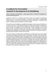
Repair Manual
ID-4000 for Windows
Digital ID Workstation
April 1995
Americas Business Center
Technical Services
201 Burlington Road
Bedford MA 01730
TEL: 1.781.386.5309
FAX: 1.781.386.5988
POLAROID
SERVICE MANUAL
ID-4000 FOR WINDOWS
Contents
Section 1: ID-4000 Description .......................................1-1
Section 2: System Configuration .....................................2-1
Section 3: Application Setup ............................................3-1
Section 4: Calibration and Adjustment .........................4-1
Section 5: ID-4000 Directories and Files........................5-1
Section 6: Troubleshooting, Repair and Maintenance .6-1
Section 7: On-Site Parts Replacement.............................7-1
Section 8: Third Party Software .....................................8-1
Appendix...........................................................................A-1
Operation and Menu Diagrams
SQLBase Reserved Words
TX-2000 Terminology, Controls and Indicators
Password Override
ID-4000 Serial Number Registration Form
Parts Catalog
Version 1.03 Upgrade Supplement
ii
Section 1: Description
Polaroid ID-4000 Service Manual
Section 1: ID-4000 Description
Contents
ID-4000 Overview ........................................................................ 1-3
Features ........................................................................................ 1-4
Hardware Components ............................................................... 1-5
ID-4000 Computer, Display, Keyboard and Mouse.................... 1-5
Input and Output Devices............................................................ 1-6
Badge-Finishing Equipment...................................................... 1-12
ID-4000 Software Components................................................. 1-13
Application Templates and Software Modules.......................... 1-13
Customer Application Builder................................................... 1-16
VAR Application Builder.......................................................... 1-16
Sample Applications.................................................................. 1-17
1-1
Section 1: Description
Polaroid ID-4000 Service Manual
1-2
Section 1: Description
Polaroid ID-4000 Service Manual
Section 1: ID-4000 Description
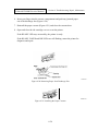
ID-4000 Overview
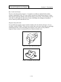
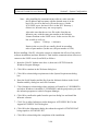
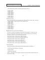
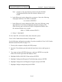
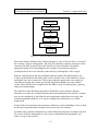
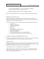
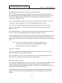
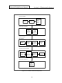
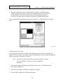
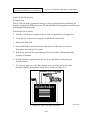
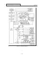
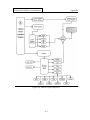
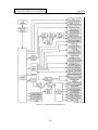
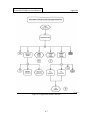
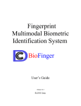
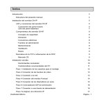
Polaroid ID-4000 for Windows is a system of hardware and software (Figure 1-1) for
producing secure photo-identification badges. It also electronically stores text data,
portraits and other identification images for viewing on the system display or for reissuing
badges.
In its full-featured configuration, ID-4000 for Windows captures and stores text data and
high-quality images (portraits, signatures, etc.) for each applicant. The system then prints
full-color, custom-designed badges on instant film, color thermal paper or other media.
With the appropriate options, the system can encode magnetic stripes or print bar-codes
on badges. Report-writing and dossier-printing modules print text data and images on
plain paper.
ID-4000 for Windows exports text and images for use by other applications and systems.
It also imports text data for creating and updating ID-4000 databases.
Figure 1-1. Typical ID-4000 Security Identification and Badging Station
1-3
Section 1: Description
Polaroid ID-4000 Service Manual
Features
ID-4000 for Windows offers the following features:
•
Instant capture, retrieval, updating and verifying of text data and images
•
Microsoft Windows operating environment for reduced operatortraining time
•
Secure, tamper-resistant and attractive portrait badges and ID cards
•
Instant individual badge issue or highly efficient batch-issue
•
Easy yet flexible customization of hardware configuration, databases,
data-entry windows and badge designs with the ID-4000 Application
Builder
•
Compatibility with a variety of input and output devices for flexible and
expandable configuration
•
Carefully designed system of passwords, audit log and optional card
history database for system security and detailed records of all activities
•
Text data import and export capability and image export capabilities for
compatibility with other systems and applications
•
Stand-alone and network configurations available
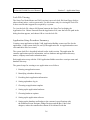
From an installation and service standpoint, ID-4000 simplifies the process of providing
the customer with a customized, working system. It was specifically designed to let VARs
and Polaroid agents to create and configure systems with minimal assistance from
Polaroid. Much of the system (databases, screens and badge designs) can be created by
the customer. (For more information, see "Software Configuration Sequence" in the
Application Setup section of this manual.)
1-4
Section 1: Description
Polaroid ID-4000 Service Manual
Hardware Components
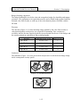
ID-4000 Computer, Display, Keyboard and Mouse
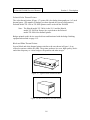
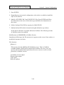
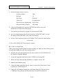
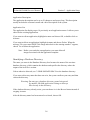
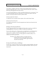
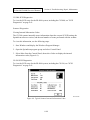
The ID-4000 computer, display and keyboard (Figure 1-2) are the core hardware
components of the ID-4000 System.
The computer controls the station, coordinates operation of all other components. For
stand-alone stations, the computer also stores the ID-4000 software and the text and image
data necessary for badging and verification operations. (Network stations may store this
data remotely.)
The display presents information, prompts and other information for guiding the operator
through data and image capture processes, badge-printing and other ID-4000 functions. It
also displays images, such as portraits and badges, for viewing by the operator.
Appropriate input and output devices are required for full functionality. However, the
computer, display, keyboard and mouse can be used alone for verification purposes.
Figure 1-2. ID-4000 Computer, Display and Mouse
1-5
Section 1: Description
Polaroid ID-4000 Service Manual
Input and Output Devices
ID-4000 input and output devices are optional components that capture images, print
badges and dossiers, encode magnetic stripes or transfer data.
Note: Additional devices not described here may become available in the future.
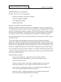
ID-4000 Input Unit
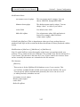
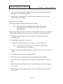
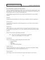
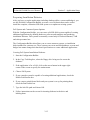
The ID-4000 Input Unit (Figure 1-3) is a video camera, electronic flash, support stand and
related electronics that capture video portraits for incorporation in photo-identification
badges printed by the ID-4000. Portraits captured with the unit are also stored on the ID4000 for a variety of uses, including reissue and identity verification.
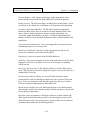
Polaroid Color Scanner
The Polaroid color scanner (Figure 1-4) digitizes portraits for incorporation in photoidentification badges printed by the ID-4000. Portraits captured with the scanner are also
stored on the ID-4000 for reissue, identity verification and other purposes.
Figure 1-3. ID-4000 Input Unit
Figure 1-4. Color Scanner
1-6
Section 1: Description
Polaroid ID-4000 Service Manual
Signature Tablet
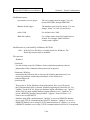
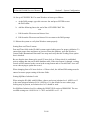
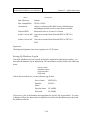
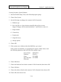
The signature tablet (Figure 1-5) captures applicant signatures for printing on badges and
storing in the ID-4000 for verification purposes. To use the tablet, the applicant signs a
pressure-sensitive writing area with a non-electronic stylus or with a ball-point pen on a
paper overlay.
Polaroid Digital Palette Color Film Recorder
The Polaroid Digital Palette Film Recorder (Figure 1-6) prints full color badge
photographs on 3-1/4 x 4-1/4 inch Polaroid Polacolor instant film. (The number of badges
per sheet depends on system configuration.)
Badges printed on this device must be diecut and laminated with the badge-finishing
equipment described on page 1-12.
Figure 1-5. Signature Tablet and Stylus
Figure 1-6. Digital Palette Color Film Recorder
1-7
Section 1: Description
Polaroid ID-4000 Service Manual
Polaroid Color Thermal Printer
The color thermal printer (Figure 1-7) prints full color badge photographs on 4 x 5-inch
thermal paper. (The number of badges per sheet depends on system configuration.)
Polaroid model TX-1500 or TX-2000 printer can be used with the ID-4000.
Note: The Hitachi model VY-300A (in the U.S.) and the Hitachi
model VY-300E (in Europe) are equivalent to the Polaroid
model TX-2000 color thermal printer.
Badges printed on this device must be diecut and laminated with the badge-finishing
equipment described on page 1-12.
Black and White Thermal Printer
Several black and white thermal printers similar to the one shown in Figure 1-8 are
offered as options with the ID-4000. The printer produces low-cost, high-quality, blackand-white temporary or visitor badges with portraits and other images.
Figure 1-7. Typical Color Thermal Printer
Figure 1-8. Black and White Thermal Printer
1-8
Section 1: Description
Polaroid ID-4000 Service Manual
Black and White PVC Printer
The black and white PVC printer (Figure 1-9) prints a black-and-white portrait, other
identification images and text directly on a vinyl (PVC) card. The card requires no
diecutting or laminating.
Laser Printer
The laser printer (Figure 1-10) prints black-and-white text and graphics for dossiers and
reports. It can also be used for printing from other Windows applications provided with
the ID-4000.
Figure 1-9. Black and White PVC Printer
Figure 1-10. Laser Printer
1-9
Section 1: Description
Polaroid ID-4000 Service Manual
Bar Code Label Printer
The bar-code label printer (Figure 1-11) produces an adhesive-backed label with an
industry-standard bar-code. The code usually contains an identification number or other
data from the applicant database and selected during system setup. After printing, the barcode label can be applied to the front or back of the badge for reading by automated
access control systems and other devices.
Magnetic Stripe Encoder
Several different magnetic stripe encoders similar to the one shown in Figure 1-12 are
available with the ID-4000. These devices embed data in an iron-oxide stripe in the badgelaminating material. After embedding, the magnetic code can be read by standard
magnetic stripe readers for automated access control and other uses.
Figure 1-11. Bar Code Label Printer
Figure 1-12. Magnetic Stripe Encoder
1-10
Section 1: Description
Polaroid ID-4000 Service Manual
Tape Drive
The tape drive (Figure 1-13) available for the ID-4000 is used with the optional backup
and restore utility (see Optional Software Modules on page 1-15) for storing backup files
on magnetic tape cartridges. It can also be used with the optional import and export
software for exchanging data with other ID-4000 stations and compatible systems.
Fax-Modem
The fax-modem (Figure 1-14) provided as an option with the ID-4000 system is used with
the optional remote diagnostics software or the optional facsimile software (see Optional
Software Modules on page 1-15). With the fax-modem and the remote diagnostics
software, the ID-4000 can be diagnosed, updated with new software, and operated via
telephone line by Polaroid technicians. With the fax-modem and the facsimile software,
the ID-4000 can transmit badge images and dossiers by telephone directly to standard
facsimile machines. It can also receive facsimiles from standard fax machines.
Figure 1-13. Tape Drive (A)
Figure 1-14. Fax-Modem
1-11
Section 1: Description
Polaroid ID-4000 Service Manual
Badge-finishing equipment
The badge-finishing devices below trim and encapsulate badges for durability and tamperresistance. This equipment or its equivalent must be used to finish badges printed with the
Polaroid color film recorder or with any of the color thermal printers available with the
ID-4000.
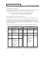
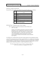
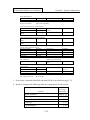
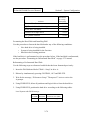
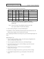
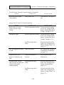
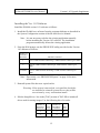
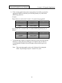
Diecutter
The diecutter (Figure 1-15) trims the badge image printed by the color film recorder or
color thermal printer to the precise size required for laminating. Four versions are
available, and the diecutter supplied with the system depends on the size of the badges and
the number printed on each sheet of film or thermal paper.
Diecutter
Trimmed Badge Size (inches)
Badges per Sheet
1-Up CR-80
2-1/8 x 3-3/8
1
2-Up CR-60 (standard)
1-3/4 x 2-1/4
2
1-Up CR-79
1-7/8 x 3-1/8
1
2-Up CR-79
1-7/8 x 3-1/8
2
Laminator
The laminator (Figure 1-16) uses precise heat and pressure to seal the diecut badge image
inside a transparent security pouch.
Figure 1-15. ID-4000 Diecutters
Figure 1-16. Laminator
1-12
Section 1: Description
Polaroid ID-4000 Service Manual
ID-4000 Software Components
ID-4000 software has several components:
• Application templates and software modules
• Customer Application Builder
• VAR Application Builder
• Sample Applications
Application Templates and Software Modules
ID-4000 for Windows hardware and software is available in a variety of configurations
called application templates. While the Security Identification and Badging Station (SIBS)
template with appropriate options is capable of full ID-4000 functionality, other templates
have only selected functions. The ID-4000 Security Verification Station (SVS) template,
for example, can only retrieve and display data and images for verification purposes.
New application templates with specialized capabilities are expected to become available
from time to time.
To prevent unauthorized distribution of functional systems, application templates
produced by VARs, agents and Polaroid sales organizations have capacity for only a few
database records. These templates become fully functional only after the application lock
file has been reconfigured and verified by Polaroid prior to delivery to the customer. (See
"Software Configuration Sequence" in the System Configuration section of this manual.)
Several standard and optional software modules are available within ID-4000 application
templates. The Microsoft Windows operating system required to run the ID-4000 software
is provided with the ID-4000.
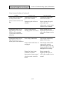
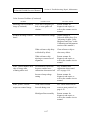
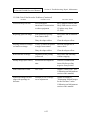
Standard Software Modules
Text record maintenance Applicant text records (name, address,
identification number, department, etc.) can be conveniently created,
retrieved, edited or deleted.
Database search features Individual or multiple applicant records can be
retrieved according to a value or range of values in one or more fields.
Portrait capture Applicant portraits can be captured and stored along with
text records (requires appropriate hardware options).
Signature capture Applicant signatures can be captured and stored with
text records (requires appropriate hardware options).
1-13
Section 1: Description
Polaroid ID-4000 Service Manual
Portrait display After capture and storage, applicant portraits can be
retrieved and viewed on the ID-4000 display for verification purposes.
Badge preview The full-color badge, including all text and images, can be
previewed on the display for verification or for inspection before printing.
Customer Application Builder The ID-4000 Customer Application
Builder modules allow users to customize ID-4000 database fields, dataentry windows, badge and dossier designs, and bar-code labels. See
"Customer Application Builder" on page 1-16 and ID-4000 Application
Builder Guide for a more detailed description of the available modules and
capabilities.
User password maintenance Users can change their own passwords for
maintaining high access security levels.
Batch record-deletion Obsolete or other appropriate records can be
retrieved via database search, then batch-deleted.
Reporting Creates text reports from ID-4000 databases.
Audit log The system maintains a log file with the details of each ID-4000
transaction. This file is available for review or for storage as a standard
ASCII text file.
Error log The error log is a file with the details of each ID-4000 system
error. This file can be viewed for diagnostic purposes and can be stored as a
standard ASCII text file.
Security lock and key editing Access to ID-4000 functions can be
customized for each user through a simple but secure system of locks and
keys. Locks are assigned to each function separately, and keys for those
locks are assigned as appropriate to individual users.
Batch output Badges, bar-code labels and dossiers can be batch-printed
and magnetic stripes can be batch-encoded, if batch operations are preferred
for any group of applicants.
Reference table maintenance Reference tables are created with the ID4000 Application Builder and provide lists for choosing the entries in ID4000 data entry fields. If necessary, these reference tables can be edited or
maintained from within the ID-4000 application.
1-14
Section 1: Description
Polaroid ID-4000 Service Manual
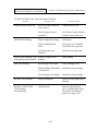
Authorizing signature capture Signatures printed on badges as a
counterfeiting deterrent can be quickly and easily recaptured without
special graphics manipulation (requires appropriate hardware options).
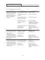
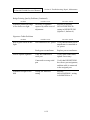
Optional Software Modules
File backup and restore Provides a fast, simple method for creating
backup copies of data and system files (requires the tape drive described on
page 1-11).
Dossier printing Prints one or more complete records, including portraits
and other images, on plain paper (requires appropriate printer).
Text data export Exports selected fields from selected applicant text
records to an ASCII text file for use by other systems or applications.
Text data import Imports applicant text data from other applications and
systems into the ID-4000 applicant database.
Text data and image export and import Exchanges text data and
identification images with other ID-4000 stations.
Card history Maintains a separate database of all activities involving
applicant records. This database can be searched to retrieve records
according to an activity, or to retrieve all records for a particular applicant
to determine the applicant's activity history.
Functional card encoding Prints bar-codes on the face of the badge or on
separate labels (requires the bar-code label printer described on page 1-10).
Also encodes magnetic stripes incorporated in the badge-laminating
material (requires a magnetic stripe encoder, described on page 1-10).
Image conversion Converts ID-4000 portraits, signatures and other images
to standard image file formats for use with other systems and applications.
Remote diagnostics Allows authorized repair technicians to diagnose,
operate and transfer new system files to your ID-4000 systems via
telephone. (Requires the optional fax-modem described on page 1-11.)
Facsimile utility Sends badge images and dossiers to any standard
facsimile ("fax") machine via telephone line. (Requires the optional faxmodem described on page 1-11.)
1-15
Section 1: Description
Polaroid ID-4000 Service Manual
Customer Application Builder
The Customer Application Builder module provided with ID-4000 application templates
allows users to customize ID-4000 databases, data-entry windows, badge and dossier
designs, and bar code labels.
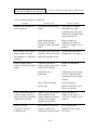
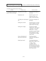
Its components include:
Application Manager. Allows the customer to create and manage
applications (sets of database data entry windows) for special purposes. For
example, a customer may use the Application Manager to create a set of
special screens for entering sensitive financial data.
Database/Screen Designer. Sets up a customized database structure for
storing applicant data.
Badge Designer. Defines and arranges the elements (data fields, fonts,
portraits, signatures, bar codes) appearing on badges printed by ID-4000
systems. Also used for setting up dossiers.
Bar Code Label Designer. Defines the bar codes (if any) printed on ID4000 badges.
See ID-4000 Application Builder Guide for detailed information about the Customer
Application Builder.
VAR Application Builder
Like the customer Application Builder, the VAR application builder includes the
Application Manager, Database/Screen Designer, Badge Designer and Bar Code Label
Designer. With these tools, VARs and agents can set up databases, data-entry screens and
badges for their customers when necessary.
The VAR Application Builder also includes the Application Setup Tool and Configuration
Builder, which are not available to customers. These tools create and configure customer
applications, and they produce floppy diskettes for installing the applications on the
customer's hardware. The VAR Application Builder can also produce installation diskettes
for additional VAR Application Builder systems.
In addition, the VAR Application Builder includes the compressed files necessary for
producing installation diskettes for each application.
1-16
Section 1: Description
Polaroid ID-4000 Service Manual
Sample Applications
An ID-4000 sample application with a database, screens and badges is shipped with each
system to help new users quickly understand and use the Application Builder tools. This
sample application also makes it possible for Polaroid Manufacturing to verify proper
hardware operation before it is shipped to the customer.
1-17
Section 1: Description
Polaroid ID-4000 Service Manual
1-18
Section 2: System Configuration
Polaroid ID-4000 Service Manual
Section 2: System Configuration
Contents
Configuration Sequence .............................................................. 2-5
ID-4000 Hardware and Software Component Summary ........ 2-6
ID-4000 Hardware....................................................................... 2-6
ID-4000 Software ........................................................................ 2-6
ID-4000 Product Tiers................................................................. 2-7
Installation Software, Tools and Equipment............................. 2-9
Tools and Equipment................................................................... 2-9
Software ...................................................................................... 2-9
Manuals ....................................................................................... 2-9
Site Preparation and Layout..................................................... 2-10
Physical Layout ......................................................................... 2-10
Lighting Conditions................................................................... 2-11
Environmental Conditions......................................................... 2-11
Computer Configuration........................................................... 2-12
NCR 3333 Configuration .......................................................... 2-12
HP Vectra VL2 4/50 Configuration........................................... 2-14
CSS Preferred 462 486 ESP-M Configuration .......................... 2-19
AT&T Globalyst 525 Configuration ......................................... 2-21
IBM ValuePoint Model 6482 Configuration............................. 2-23
Drive and Board Configuration ............................................... 2-25
Support Board Configuration .................................................... 2-25
Cardinal Snap Plus Board Configuration .................................. 2-26
Future Domain TMC-850M SCSI Card Configuration............. 2-27
3Com 3c509 Combo Ethernet Board Installation...................... 2-30
Serial Port Board Configuration ................................................ 2-30
Adaptec SCSI Board Configuration .......................................... 2-31
Connor 2150/2250 Tape Drive Configuration........................... 2-32
Connor 2525 525MB Tape Drive Setup.................................... 2-33
2-1
Section 2: System Configuration
Polaroid ID-4000 Service Manual
Input and Output Device Setup................................................ 2-34
Polaroid CI-5000 Plus Film Recorder Setup ............................. 2-34
Polaroid TX-1500 Thermal Printer Setup.................................. 2-35
Polaroid TX-2000 Thermal Printer Setup.................................. 2-36
Nisca PVC Printer Setup ........................................................... 2-36
Input Unit Assembly and Setup................................................. 2-37
Polaroid CS-500i Color Scanner Setup ..................................... 2-40
Magtek MT-80 Magnetic Stripe Encoder Setup........................ 2-41
Laminator Setup ........................................................................ 2-42
Intermec 3000A Barcode Labeler Setup ................................... 2-43
Sony 610 Black and White Thermal Printer Setup.................... 2-44
Sony 860 Black and White Thermal Printer Setup.................... 2-44
Inforite Signature Tablet Setup.................................................. 2-45
DataCard B&W PVC Printer (ImageCard I) Setup ................... 2-45
DataCard Color PVC Printer (ImageCard II) Setup .................. 2-46
AT&T Paradyne 14.4 FAX/Modem Setup................................ 2-49
LaserJet IV Printer Setup........................................................... 2-49
Hardware Key Installation and Setup........................................ 2-50
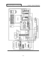
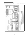
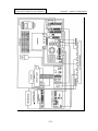
Cable Connections ..................................................................... 2-51
System Cabling.......................................................................... 2-51
SCSI Device Address Organization .......................................... 2-55
SCSI Disk Tape, CI-5000 Plus and CS-500i Cabling ............... 2-55
SCSI Board Configuration ........................................................ 2-56
SCSI Cabling with 850m Controller Board............................... 2-56
Magnetic Stripe Encoder Cabling.............................................. 2-57
Intermec 3000A Barcode Labeler Cabling ................................ 2-58
DataCard Black and White PVC Printer Cabling...................... 2-58
TX-2000 (VY-300) Color Thermal Printer Cabling.................. 2-59
Cabling Options with Cardinal and Support Boards ................. 2-60
Software Installation and Setup ............................................... 2-61
Software Elements..................................................................... 2-61
Software Installation Overview ................................................. 2-61
Software Installation: NCR 3333............................................... 2-61
Software Installation: HP Vectra VL2 4/50............................... 2-64
Software Installation: CSS 462 486 ESP-M.............................. 2-68
Installing the CSS 462 IDE/IO Device Driver........................... 2-69
Software Installation: AT&T Globalyst..................................... 2-69
Software Installation: IBM ValuePoint 6482 ............................ 2-71
Formatting the Hard Disk and Installing DOS .......................... 2-74
Installing Windows 3.1.............................................................. 2-76
2-2
Section 2: System Configuration
Polaroid ID-4000 Service Manual
Software Installation and Setup (Continued)
Installing the Mouse Driver....................................................... 2-77
Installing the Cardinal SnapPlus Windows Driver .................... 2-78
Installing Close-Up 5.0.............................................................. 2-78
Installing Crystal Reports Pro 3.0.............................................. 2-80
Installing FastBack PLUS 6.0 ................................................... 2-80
DOS/Windows SQLBase Server Installation ............................ 2-82
Gupta SQLBase Server Installation on Novell Netware Server 2-84
Client Software Installation for Oracle on SCO UNIX Server .. 2-87
Client Software Installation for Oracle on NetWare Server ...... 2-89
Client Software Installation for Informix on SCO UNIX Server ... 2-89
SQL LAN (Novell) DataBase Software Installation.................. 2-92
Novell Netware Client Side Software Setup.............................. 2-99
UNIX (TCP/IP) Client Side Software Setup ........................... 2-100
Using PC/TCP to Mount UNIX Drives ................................... 2-102
Modifying STARTUP.NCF for NetWare................................ 2-103
Setting Up Stand-Alone Database with Gupta SQLBase Server . 2-103
3Com 3c509 Combo Ethernet Board Configuration ............... 2-105
Bar Code Font Installation....................................................... 2-106
ID-4000 Core Installation........................................................ 2-107
Setting Date and Time Formats ............................................... 2-108
Setting SQLBase Isolation Levels ........................................... 2-108
Optimizing DOS and Windows............................................... 2-109
Renaming Oracle DLL Files.................................................... 2-110
Loading PowerSCSI! for Tape Drives..................................... 2-111
Installing Adaptec EZ-SCSI Lite Software.............................. 2-111
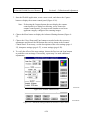
Setting Up Multiple Area of Interest Scanning ....................... 2-112
Specifying Film Type for the CI-5000 Plus ............................ 2-118
DataCard Black and White PVC Printer Software Setup ........ 2-119
DataCard ImageCard II Printer Driver Installation.................. 2-119
Fargo Printer Driver Installation.............................................. 2-120
System Calibration .................................................................. 2-120
Functional Check ..................................................................... 2-121
Database/Screen Designer Test ............................................... 2-121
Badge Designer Test................................................................ 2-122
Log-In and Data Entry Test ..................................................... 2-123
Portrait and Signature Capture Test......................................... 2-124
2-3
Section 2: System Configuration
Polaroid ID-4000 Service Manual
2-4
Section 2: System Configuration
Polaroid ID-4000 Service Manual
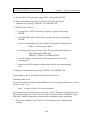
Section 2: System Configuration
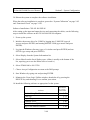
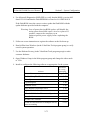
Configuration Sequence
The ID-4000 system configuration sequence is generally as follows:
Step
Page
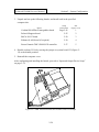
1. Prepare the installation site.
2-10
2. Configure the ID-4000 computer.
2-12
3. Configure and install the computer drives and
boards.
2-21
4. Unpack and set up the input and output devices.
2-34
5. Connect the cables.
2-51
6. Install the software.
2-61
7. Calibrate the system.
2-120
8. Perform the functional test.
2-121
Some installations may also require you to use the VAR Application Builder to create the
ID-4000 application and produce installation diskettes prior to the installation process.
The Application Setup section of this manual provides detailed instructions for these
installations.
2-5
Section 2: System Configuration
Polaroid ID-4000 Service Manual
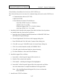
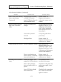
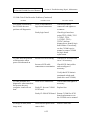
ID-4000 Hardware and Software Component Summary
ID-4000 Hardware
PC
One of the following:
• NCR System 3333 Model 1020 486/33
• HP Vectra Model VL2 4/50
• CSS Labs Preferred 462 Model 486 ESP-M
• AT&T Globalyst 525
• IBM ValuePoint System 6384
• IBM ValuePoint 466 DX2/Dp
• Digital DECpc LPx PC7-66
RAM
Two 4MB SIMM modules (8 MB total); 16 MB RAM
Storage
• 120, 520 or 1260 MB IDE Hard Drive
• 3.5" 1.44 MB Floppy Drive or 3.5"/5.25" (1.44 MB/1.2
MB) Floppy Drive
• Connor Streaming Tape 250 or 525 Drive
Computer
Boards
•
•
•
•
•
•
External Devices
• Polaroid CI-5000 Plus Film Recorder (Digital Palette)
or Polaroid TX-1500 Color Thermal Printer
• AT&T Paradyne External 14.4 FAX/Modem
• Universal Input Assembly
• Hardware Key
• Polaroid CS-500i Color Scanner
• Inforite Signature Tablet
• TX-2000 (Hitachi VY-300) Color Thermal Printer
• Sony B&W Thermal Printer
• DataCard B&W PVC Printer
• HP Laserjet IV Laser Printer
Future Domain TMC-850M SCSI board
Polaroid Support Board
Cardinal SnapPlus Frame grabber board
Boca IO/AT Board (+2 Serial, +1 Parallel)
DigiBoard DigiCHANNEL Com/Xi (+4 Serial)
3 COM Card LAN Board (3c509)
ID-4000 Software
Standard
software
• ID-4000 application
• Close-Up 6.0
• FastBack Plus 6.0 (included with Connor tape drive)
2-6
Section 2: System Configuration
Polaroid ID-4000 Service Manual
Other software
• Crystal Reports Pro 3.0
• SQLBase for Windows 5.1.4
• Bear Rock PrintBar Bar Code Fonts for Windows
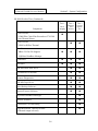
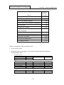
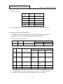
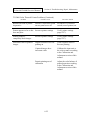
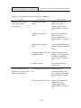
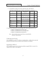
ID-4000 Product Tiers
Component
Tier 1
Tier 2
Tier 3
Basic
Badging
Badging
and
Utilities
Security
Application
n
n
n
n
n
n
n
n
n
n
n
Universal Input Unit
CCD Color Video Camera with Perfect Portrait
Flash Lighting System
System Control Unit
80486 PC, 8MB RAM, VGA Color Monitor,
Keyboard, 1.2 MB Floppy Disk Drive, 2 Serial
Ports, 1 Parallel Port, SCSI Controller Board,
Video Capture/Processing Boards, Hardware Key,
Calibration Target
Software and Documentation
ID-4000 Application Builder, ID-4000 Security ID
and Badging 3.0, ID-4000 User Documentation,
MS Windows 3.1, and DOS 6.0.
Hard Drive
IDE 120 MB (Due to rapid technology and market
changes, available hard disk capacities may vary.
Minimum capacities are guaranteed.)
n
Hard Drive
IDE 520 MB or IDE 1260 MB (Due to rapid
technology and market changes, available hard
disk capacities may vary. Minimum capacities are
guaranteed.)
2-7
Section 2: System Configuration
Polaroid ID-4000 Service Manual
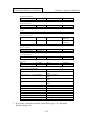
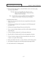
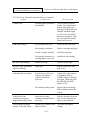
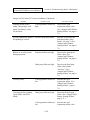
ID-4000 Product Tiers (Continued)
Tier 1
Tier 2
Tier 3
Basic
Badging
Badging
and
Utilities
Security
Application
n
n
n
n
n
Laminator
n
n
n
Diecutter
n
n
n
340 MB Hard Disk Drive
n
n
14.4 KBPS Fax Modem
n
n
Remote Diagnostics
n
n
250 MB Tape Drive
n
n
Data Backup Software
n
n
Import/Export Software
n
n
Component
Color Printer
CI-5000 Plus Color Film Recorder or TX-1500
Color Thermal Printer
n
Color Printer
CI-5000 or Hi Res Thermal
DataBase
• dBase IV Flat File Support
• SQLBase DataBase Manager
SQLBase DataBase Manager
n
Dossier Software
n
Functional Card Encoding
n
High-Resolution Thermal Printer
(if thermal output selected)
n
2-8
Section 2: System Configuration
Polaroid ID-4000 Service Manual
Installation Software, Tools and Equipment
The following tools, equipment, software and manuals should be available during ID-4000
System installation.
Tools and Equipment
• Multimeter
• Install/Field Service Toolkit
• Color calibration card
• Grounding strap
• Loop back connectors, serial and parallel*
Software
• Microsoft Diagnostics (included with MS DOS)
• Bootable diskette
• NCR User Diagnostics diskette
• Norton Disk Doctor*
Manuals
• ID-4000 Service Manual
• MS DOS 6 Operating Manual
• ID-4000 for Windows User Guide
• ID-4000 for Windows Application Builder Guide
* Recommended but not required.
2-9
Section 2: System Configuration
Polaroid ID-4000 Service Manual
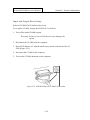
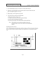
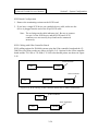
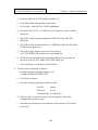
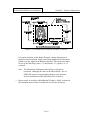
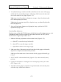
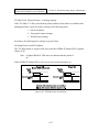
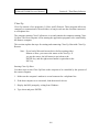
Site Preparation and Layout
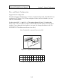
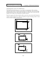
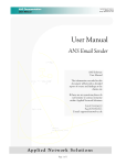
Physical Layout
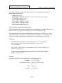
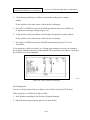
Sufficient space must be available to allow the layout shown in (Figure 2-1). Be sure the
operator has sufficient workspace.
The installation technician should call ahead to verify space availability before proceeding
to the site.
Note: Particularly important is the camera-to-subject distance in
Figure 2-1. Also, the CI-5000 film recorder (1) and the
monitor (2) must be at least 16 inches apart to prevent
electromagnetic interference.
Backdrop
Applicant
5 ft for
16mm lens
(standard)
Portrait Camera
1
2
3 - 4 ft
4 - 6 ft
Operator
Figure 2-1. Typical Polaroid ID-4000 Layout
2-10
Section 2: System Configuration
Polaroid ID-4000 Service Manual
Lighting Conditions
For the best results Polaroid recommends using 5500° Kelvin fluorescent lamps which
provide an even distribution of light. At a minimum the system should be in consistent
indirect light that is neither too bright nor too dark. It is important to keep the system away
from direct sunlight and windows where the light varies according to the time of day and
weather.
The applicant should sit with his or her back against a backdrop. This will minimize
shadows behind the applicant in the picture.
Environmental Conditions
Because all electrical equipment, especially computers, generates a steady amount of
potentially damaging heat, it is important that air circulate freely around the equipment all
the time. Ideally the ID-4000 should be in an air conditioned space. The equipment should
never be in direct sunlight.
In addition, the workspace should be dry, have normal humidity, and be free of dust.
(Dust and humidity are harmful to computers and other electronic equipment.)
To avoid interference with the ID-4000, connect any other electronic systems (other
computers, radios, etc.) to a different power circuit.
2-11
Section 2: System Configuration
Polaroid ID-4000 Service Manual
Computer Configuration
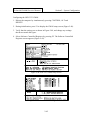
NCR 3333 Configuration
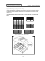
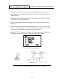
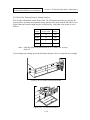
Use the steps below to install drives and boards in the NCR System 3333. (This system
requires no initial setup prior to drive and board installation.)
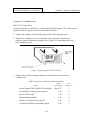
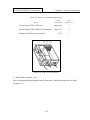
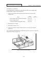
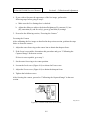
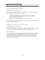
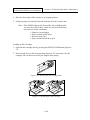
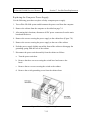
1. Unpack the computer, monitor and keyboard from their shipping boxes.
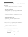
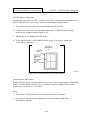
2. Remove the computer cover by turning the system keylock to its unlocked
position, removing the three retaining screws (Figure 2-2) and sliding the cover
back and then upward.
Figure 2-2. Removing the NCR 3333 Cover
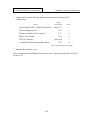
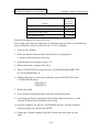
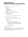
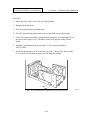
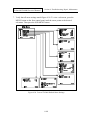
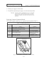
3. Unpack and set up the following boards, and install each in the specified
computer slot:
NCR 3333 Systems: All Except Verification Station
Setup
Instructions
Board
Future Domain TMC-850M SCSI controller
Slot
(Figure 2-3)
Page 2-27
1
Second BOCA serial port (if required)
2-30
2
BOCA IO/AT board
2-30
3
Polaroid Support board
2-25
4
Ethernet (LAN) board (if required)
2-30
5
Cardinal SNAPPlus Framegrabber board
2-26
6
2-12
Section 2: System Configuration
Polaroid ID-4000 Service Manual
NCR 3333 Systems: Verification Station Only
Setup
Instructions
Slot
(Figure 2-3)
Cirrus Logic VLBus video card
none req’d
1
Future Domain TMC-850M SCSI controller
Page 2-27
2
2-30
5
Board
Ethernet (LAN) board (if required)
Figure 2-3. NCR 3333 Slot Numbers
4. Reinstall the computer cover.
After configuring and installing the boards, proceed to “Input and Output Device Setup”
on page 2-34.
2-13
Section 2: System Configuration
Polaroid ID-4000 Service Manual
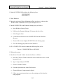
HP Vectra VL2 4/50 Configuration
Configuring the HP Vectra VL2 4/50 requires the following two procedures:
• Initial setup
• Installing drives and boards
Initial Setup
Perform this procedure to set up the HP Vectra VL2 4/50 computer before installing any
drives or boards.
Note: This procedure requires seven blank, formatted 3½” floppy
diskettes.
1. Unpack the computer, monitor and keyboard from their shipping boxes.
2. Connect the power cords and cables according to instructions provided with the
computer.
3. Turn on the monitor and the computer.
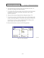
4. Follow the on-screen instructions to install WFW 3.11.
5. Start Windows and verify proper system operation with mouse.
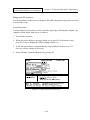
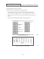
6. Double-click on the HP Disk Creation icon and choose Create Diskettes.
7. Choose DOS/Mouse, Plug and Play, and Advanced Power Management.
8. Follow the on-screen instructions to create the diskettes.
9. Close Windows and turn off the computer and monitor.
2-14
Section 2: System Configuration
Polaroid ID-4000 Service Manual
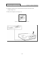
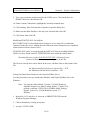
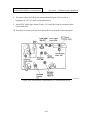
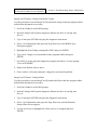
10. Unplug the computer power cord and unlock the keylock on the back of the
computer (Figure 2-4).
11. Remove the computer cover (Figure 2-5).
Figure 2-4. Unlocking the HP Vectra Cover
Figure 2-5. Removing the HP Vectra Cover
2-15
Section 2: System Configuration
Polaroid ID-4000 Service Manual
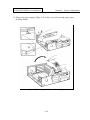
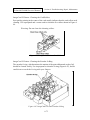
11. Remove the power supply (Figure 2-6) to allow access for moving jumpers and
installing boards.
Figure 2-6. Removing the HP Vectra Power Supply
2-16
Section 2: System Configuration
Polaroid ID-4000 Service Manual
12. Disable the on-board VGA adapter by moving the JP8 jumper on the mother
board from pins 2-3 to pins 1-2 (Figure 2-7).
After disabling the on-board VGA adapter, go to drive and board hardware installation
instructions below.
Figure 2-7. Disabling VGA on the Mother Board
2-17
Section 2: System Configuration
Polaroid ID-4000 Service Manual
Installing Drives and Boards
Use the steps below to install drives and boards in the HP Vectra computer after
configuring the computer as described above.
1. Unpack and set up the following boards, then install each in the specified
computer slot:
Board
Setup
Instructions
Slot
(Figure 2-8)
Future Domain TMC-850M SCSI controller
Page 2-26
1
Polaroid Support board
Page 2-25
2
Cardinal SNAPPlus Framegrabber board
Page 2-25
3
2. Reinstall the power supply.
3. Reinstall the computer cover.
4. Connect the external Colorado Trakker tape drive (if used) to the computer
parallel port.
After configuring and installing the boards and the tape drive, proceed to “Input and
Output Device Setup” on page 2-34.
Figure 2-8. HP Vectra Slot Numbers
2-18
Section 2: System Configuration
Polaroid ID-4000 Service Manual
CSS Preferred 462 486 ESP-M Configuration
Configuring the CSS Preferred 462 486 ESP-M requires the following two procedures:
• Initial hardware check
• Installing drives and boards
Initial Hardware Check
Perform this procedure to verify that you have the correct CSS Preferred 462 486 ESP-M
hardware before you install any drives or boards.
1. Unpack the computer, monitor and keyboard from their shipping boxes.
2. Connect the power cords and cables according to instructions provided with the
computer. (Do not change the system from its out-of-the-box configuration.)
3. Turn on the monitor and the computer.
4. Verify that the system operates properly.
5. Run Microsoft Diagnostics (type c:\dos\msd and press ENTER) to verify that
the system has the proper board revision number and model number (462
model 486-ESP-M, BIOS dated 08/08/93).
6. Turn off the system.
Installing Drives and Boards
Use the steps below to install drives and boards in the CSS Preferred 462 486 ESP-M
computer after checking the hardware as described above.
1. Unplug the computer power cord.
2. Remove the computer cover.
3. Remove the VL video board from its slot.
4. Remove the ground wire from the video board and the mother board.
5. Connect the mouse cable to COM2.
2-19
Section 2: System Configuration
Polaroid ID-4000 Service Manual
6. Unpack and set up the following boards, then install each in the specified
computer slot:
Setup
Instructions
Board
Future Domain TMC-850M SCSI controller
Slot*
Page 2-27
1
Polaroid Support board
2-25
3
Ethernet (LAN) board (if required)
2-30
4
BOCA IO/AT board
2-30
6
IDE VL Controller
none req’d
Cardinal SNAPPlus Framegrabber board
2-26
7
8
*Slot 1 is nearest the power supply.
7. Reinstall the computer cover.
After configuring and installing the boards, proceed to “Input and Output Device Setup”
on page 2-34.
2-20
Section 2: System Configuration
Polaroid ID-4000 Service Manual
AT&T Globalyst 525 Configuration
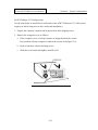
Use the steps below to install drives and boards in the AT&T Globalyst 525. (This system
requires no initial setup prior to drive and board installation.)
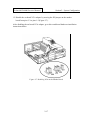
1. Unpack the computer, monitor and keyboard from their shipping boxes.
2. Remove the computer cover as follows:
a. If the computer cover is locked (systems are shipped unlocked), use the
key provided with the computer to unlock the system lock (Figure 2-9).
b. Remove the three cabinet retaining screws.
c. Slide the cover backward slightly, then lift it off.
Figure 2-9. Removing the AT&T Globalyst Cover
2-21
Section 2: System Configuration
Polaroid ID-4000 Service Manual
3. Unpack and set up the following boards, and install each in the specified
computer slot:
Setup
Instructions
Slot
(Figure 2-10)
Page 2-30
1
Cardinal SNAPPlus Framegrabber board
2-26
2
Polaroid Support board
2-25
3
Second BOCA serial port (if required)
2-30
4
Adaptec SCSI controller (used with Nisca printer)
2-31
5
Future Domain TMC-850M SCSI controller
2-27
6
Ethernet (LAN) board (if required)
2-30
7
Board
BOCA IO/AT board
4. Reinstall the computer cover.
After configuring and installing the boards, proceed to “Input and Output Device Setup”
on page 2-34.
Figure 2-10. AT&T Globalyst Slot Numbers
2-22
Section 2: System Configuration
Polaroid ID-4000 Service Manual
IBM ValuePoint Model 6482 Configuration
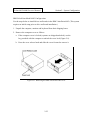
Use the steps below to install drives and boards in the IBM ValuePoint 6482. (This system
requires no initial setup prior to drive and board installation.)
1. Unpack the computer, monitor and keyboard from their shipping boxes.
2. Remove the computer cover as follows:
a. If the computer cover is locked (systems are shipped unlocked), use the
key provided with the computer to unlock the cover lock (Figure 2-9).
b. Press the cover release latch and slide the cover forward to remove it.
Figure 2-11. Removing the IBM ValuePoint 6482 Cover
2-23
Section 2: System Configuration
Polaroid ID-4000 Service Manual
3. Unpack and set up the following boards, and install each in the specified
computer slot:
Setup
Instructions
Board
Cardinal SNAPPlus Framegrabber board
Slot
(Figure 2-12)
Page 2-26
1
Polaroid Support board
2-25
2
BOCA IO/AT board
2-30
3
Ethernet (LAN) board (if required)
2-30
4
Future Domain TMC-850M SCSI controller
2-27
5
4. Disable on-board VGA by moving the jumper on system board J32 (Figure 212) to the disable position.
5. Reinstall the computer cover.
After configuring and installing the boards, proceed to “Input and Output Device Setup”
on page 2-34.
Figure 2-12. IBM ValuePoint 6482 Slot Numbers and VGA Jumper
2-24
Section 2: System Configuration
Polaroid ID-4000 Service Manual
Drive and Board Configuration
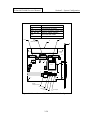
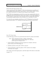
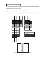
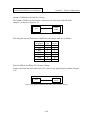
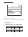
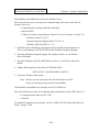
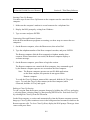
Support Board Configuration
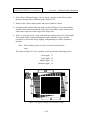
The Polaroid support board (Figure 2-13) has a 10-position dip switch which should be set
to address 0x338 (Figure 2-14). When setting the switches, invert the board so you can
read the switch numbers.
For this switch, OFF = 1 and ON = 0. The settings shown in Figure 2-14 produce the
binary value of 11 0011 1000 or 338 hex, which is the board I/O address. Use only these
settings. (If you change the board address, you must also change the address in the file
SUPPORT.INI. The address must be an even value.)
Note: Position 10 is not used, but set it to ON.
Figure 2-13. Support Board Switch Location
ON
OFF
n
n
n
1
2
3
n
4
n
n
n
5
6
7
n
n
n
8
9
10
Figure 2-14. Support Board Switch Settings
2-25
Section 2: System Configuration
Polaroid ID-4000 Service Manual
Cardinal Snap Plus Board Configuration
The Cardinal Snap Plus board requires no jumper changes from the original factory
settings, shown in Figure 2-15.
Software configurable parameters are located in the CARDINAL.INI file.
Figure 2-15. Cardinal Board Configuration
2-26
Section 2: System Configuration
Polaroid ID-4000 Service Manual
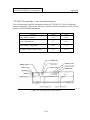
Future Domain TMC-850M SCSI Card Configuration
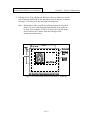
Remove the three termination resistor packs RN1, RN2 and RN3 (Figure 2-16) only if
there is an internal SCSI device (such as the Archive Viper Tape drive). When there is an
internal SCSI device, be sure to terminate it. When connecting to an external SCSI device,
be sure to use a MAC (25-pin to 50-pin) SCSI cable (1B0351A) for the CI5000 Plus
Digital Palette or a MAC (25-pin to 50-pin) SCSI cable for the CS-500i color scanner.
Termination on the controller and an internal device is in the form of resistor packs
(usually three in a row). A resistor pack is in the form of a SIPP. The termination on an
external device has a connector on each end, without an actual cable.
The SCSI card BIOS (the EPROM located in the lower left corner of the card) is only
necessary if a SCSI hard drive is connected to the controller. In cases where a SCSI hard
drive is not included on the system, the BIOS should be removed.
Interrupt
The interrupt setting defines the interrupts used by the controller. The controller’s
interrupt setting cannot be used by other devices in the computer. Interrupt jumpers are
labeled W6 and W7.
Interrupt Selection
W6
Pin 1/2
W7
Pin 2/3
IRQ
Open
Closed
5
Closed
Open
3
Open
Open
None
2-27
Diagram
Default
ID-4000
Section 2: System Configuration
Polaroid ID-4000 Service Manual
J1
External SCSI connector
J2
Internal SCSI connector
RN1 RN2 RN3 Passive termination resistor packs
RN 1
W1 W2 W3
W5
Memory address selection
Zero wait state enable
W6 W7
Interrupt selection
RN 2
NO T
TE R M I N A TE D
J2
RN 3
J2
2
1
+
50 I NTERNA L
49
SCSI
+
C1 2
+
1
1
RN 1
C9 R3 1 RN 3
C4
C5
1 . 5 AMP
C11
C1 0
C1 3
1
J1
F1
D1
R1
9 C5 0
C8
C2
W6 W7
1
I RQ3
U5
IRQ5 W1 W2
1
1
W3
W5
1
+
C3
P1
C1 4
A1
W6/W7
Jumped as shown
W1 Jumped
W2 Jumped
W3 Jumped
W5 Jumped
Figure 2-16. Future Domain SCSI Card (TMC-850M) Configuration
2-28
Section 2: System Configuration
Polaroid ID-4000 Service Manual
Memory Address
The memory address setting defines the section of computer memory reserved for
exclusive use by the controller’s ROM BIOS. It cannot be used by other devices in the
computer.
Memory address jumpers are labeled W1, W2, and W3.
The default memory address range from CA00h to CBFFh (8K).
Chase to DEOO-DFFF
Memory Address Selection
Use the following table to select a memory address.
Memory Address Selection
W3
Base
Memory
Address
Open
1-2, 3-4
CA00h
Closed
Open
1-2, 3-4
C800h
Open
Closed
1-2, 3-4
CE00h
Closed
Closed
1-2, 3-4
DE00h
Open
Open
1-3, 2-4
E800h
Open
Closed
1-3, 2-4
EC00h
W1
W2
Open
Diagram
W1 W2
W3
ID-4000
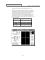
Termination
Remove all termination packs from RN1, RN2, and RN3 (Figure 2-17).
1
RN1
1
RN2
1
RN3
Figure 2-17. RN1, RN2 and RN3 on TMC-850N
2-29
Factory
Section 2: System Configuration
Polaroid ID-4000 Service Manual
Zero Wait State
The zero wait state setting determines whether or not the controller takes advantage of the
fast operation (“zero wait”) on IBM AT computers. Zero wait state is disabled at the
factory because some AT-compatibles implement the fast operation differently from IBM,
and some XT/AT compatibles use the zero wait state feature for other functions.
Enable this feature by jumpering W5 as shown below, if your installation requires it.
Zero Wait State Selection
W5
Function
Diagram
Closed
Zero Wait State enabled
Open
Zero Wait State disabled
Factory
ID-4000
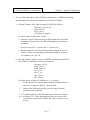
3Com 3c509 Combo Ethernet Board Installation
If the system configuration calls for the 3Com 3c509 Combo Ethernet board, install it in
the computer and attach it to the desired connection type (10BaseT, 10 Base5).
When performing the software intallation, be sure to perform the board configuration
described on page 2-105.
Serial Port Board Configuration
The serial port handler in the Version 3 software supports multi-port serial boards in
addition to the standard IBM ports. The ports are numbered differently in the various
configurations described below.
Note: Because of ID-4000 flexibility, device assignments can vary.
Choosing the Appropriate Boards
Use the Boca Board in the standard configuration. This provides two additional serial
ports and one additional parallel port.
If more serial ports are needed use the DigiBoard DigiCHANNEL COM/Xi which will
increase the number of serial ports by four. On NCR 3333 systems with two on-board
serial ports, for example, the DigiBoard increases the total number of serial ports to six.
2-30
Section 2: System Configuration
Polaroid ID-4000 Service Manual
BOCA AT/IO Setup
The BOCA AT/IO board supports up to two serial ports and one parallel port. The
additional serial port is installed by adding a cable.
The jumper settings shown in Figure 2-18 enable COM3 and LPT2.
Note: INT9 should not be used under any circumstances as this is
the interrupt line for the second interrupt controller.
DigiBoard DigiCHANNEL COM/Xi Setup
To setup the DigiBoard, enter Windows and run the setup program found in the Windows
directory of the DigiBoard diskette.
Figure 2-18. Boca Board Jumper Settings
Adaptec SCSI Board Configuration
When using the Nisca PVC printer with the ID-4000, an Adaptec SCSI board must be
installed in the ID-4000 computer as follows:
1. Unpack the Adaptec SCSI board and disable its BIOS and floppy drive
controller by setting the board switches as follows:
Adaptec Switch
Setting
1
2
3
4
5
6
7
8
on
off
off
off
on
on
on
on
Setting Description
Termination installed
I/O port 330-333h
Floppy disabled
BIOS address disabled
2-31
Section 2: System Configuration
Polaroid ID-4000 Service Manual
2. Install the board in a 16-bit ISA slot.
After installing the Adaptec board, set up and connect the Nisca printer as described on
page 2-36. Then install the Adaptec SCSI software (provided with the Adaptec board) as
described on page 2-111.
Connor 2150/2250 Tape Drive Configuration
The tape drive standard configuration is set up in conjunction with an IDE hard drive.
Install the terminating resistors and plug the drive into the end of the SCSI cable.
The factory configuration has only two jumpers. Three additional jumpers (not provided)
must be added to achieve the proper configuration, shown in Figure 2-19.
Note: If the tape drive is used with a SCSI hard drive, the
terminating resistors must be removed and the tape drive
should be in the middle connector of the SCSI cable. The
terminating resistors are in SIPP form and are located
between the 50-pin SCSI connector and the circuit board at
the rear of the drive. The tape drive SCSI ID should be set to
6.
Figure 2-19. Connor Tape Drive Jumper Settings
2-32
Section 2: System Configuration
Polaroid ID-4000 Service Manual
Connor 2525 525MB Tape Drive Setup
The Connor 2525 525 MB tape drive has the following specifications:
Capacity:
525MB/320MB (formatted)
Tape speed:
90 or 120 ips
Transfer rate: 2MB/sec burst, 180KB/sec or 240KB/sec average
The factory configuration has four jumpers. Install or reconfigure the existing jumpers
according to Figure 2-20. It shows the drive set up as SCSI ID 6 with Autosense on.
The jumper blocks are located in a slot cut in the left side, rear lower corner of the tape
drive.
J5
Rear
of
drive
1 2 3
J4
1 2 3 4 5
Figure 2-20. Connor 525 MB Tape Drive Jumper Settings
2-33
Section 2: System Configuration
Polaroid ID-4000 Service Manual
Input and Output Device Setup
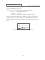
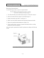
Polaroid CI-5000 Plus Film Recorder Setup
To set up the CI-5000, change the SCSI ID to 2 as follows:
1. Turn off the entire ID-4000 system.
Warning: Failure to turn off all devices may damage the
system.
2. Disconnect the CI-5000 from the computer.
3. Reset SCSI address to 2 with the small rotary switch on the back of the CI5000 (Figure 2-21).
4. Reconnect the CI-5000 to the computer.
5. Turn on the CI-5000, then turn on the computer.
Figure 2-21. SCSI ID Switch on CI-5000 Film Recorder
2-34
Section 2: System Configuration
Polaroid ID-4000 Service Manual
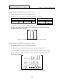
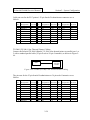
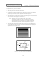
Polaroid TX-1500 Thermal Printer Setup
This procedure sets the TX-1500 color thermal printer for interlaced input, the correct
setting for ID-4000 systems.
1. Set the rear panel DIP switches as shown in Figure 2-22.
2. Verify that only the following LEDs are lighted on the front of the TX-1500:
• POWER
• READY
• FRAME
• RGB
If necessary, set the front panel lights correctly by pressing the corresponding
buttons.
If only the READY light is blinking, wait until it is steady before proceeding.
If the READY, PAPER and INK lights are all blinking, paper is jammed in the
printer. See the Troubleshooting and Maintenance section of this manual for
jam-clearing procedures.
If the PAPER or INK light is blinking, the paper or ink cartridge needs
replenishment. See the Troubleshooting and Maintenance section of this
manual for the procedures.
Note: Synchronization is not necessary when the printer is set for
interlaced input.
A
1
2
3
4
ON
OFF
5
6
7
8
9
10
n
n
n
n
n
n
n
n
n
n
1
2
3
4
5
6
7
8
9
10
n
n
n
n
n
n
n
n
n
n
B
ON
OFF
Figure 2-22. TX-1500 Rear Panel Switch Settings
2-35
Section 2: System Configuration
Polaroid ID-4000 Service Manual
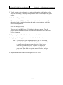
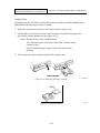
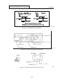
Polaroid TX-2000 Thermal Printer Setup
Connect the Polaroid TX-2000 (Hitachi VY-300) color thermal printer to parallel port 2
with a standard parallel printer cable (25 pin D-sub to 36 pin Centronics cable). Connect
the 25 pin D-sub end to the CPU and the 36 pin Centronics end to the printer.
The TX-2000 color thermal printer must also be set up to turn on automatically when it is
plugged in or when the ID-4000 power strip switch is turned on. This setup command is in
the TX-2000 driver, and it must be sent to the printer only once during initial installation
for permanently setting the printer to turn on whenever it is connected to AC power.
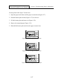
To execute this setup command, manually turn on the TX-2000 printer by pressing the
Operate button (Figure 2-23). Then print one image using the Windows printer driver.
Figure 2-23. TX-2000 Operate Button
Nisca PVC Printer Setup
Use the following procedure to set up and connect the Nisca PVC printer to the ID-4000.
Note: Before starting this procedure, configure and install the
Adaptec SCSI board as described on page 2-31. (The Nisca
printer requires the Adaptec board.)
1. Follow installation instructions in the Nisca printer User’s Manual. (The Nisca
printer’s factory-set SCSI ID setting is 4.)
2. Install the terminator on the printer’s SCSI-2 connector.
3. Use the SCSI cable to connect the printer’s SCSI-1 connector to the Adaptec
SCSI board in the computer.
After setting up and connecting the printer, install the Adaptec SCSI software as described
on page 2-111.
2-36
Section 2: System Configuration
Polaroid ID-4000 Service Manual
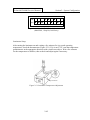
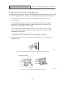
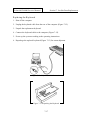
Input Unit Assembly and Setup
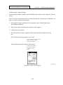
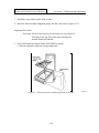
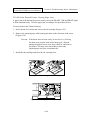
1. Connect the 9 pin D-sub connector to the RGB Sync/Video out connector. Set
the tint in middle and daylight/indoor to daylight position.
2. Connect DIN connector to video camera DC12V.
3. Attach the connector bracket by screwing the camera mount bracket to the
bottom of camera.
4. Slide the connector cover in place and attach it with two screws (Figure 2-24).
Figure 2-24. Camera Wiring and Connector Cover
2-37
Section 2: System Configuration
Polaroid ID-4000 Service Manual
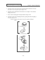
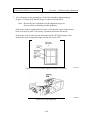
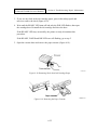
5. Attach the strobe to the strobe bracket and latch with the strobe lock. Be sure
the strobe is set to one quarter power (Figure 2-25).
6. Attach the strobe and bracket to the connector cover (Figure 2-24) with three
Phillips-head screws.
7. Screw camera mounting pole into input unit base (Figure 2-26).
8. Attach the camera to the mounting bracket by opening the latch and angling it
into place (Figure 2-26).
Caution: Be sure the camera is secure by gently rocking in
place.
4
_
= 1/4 power
2
Figure 2-25. Strobe Power Dial
Figure 2-26. Camera Mounting Pole
2-38
Section 2: System Configuration
Polaroid ID-4000 Service Manual
9. Confirm that the camera switches and dials (Figure 2-27) are set as follows. (If
necessary, remove the plastic cover, set the switches and reinstall the cover.)
Switch or Dial
GAIN
Setting
FIX
GAIN (dB Level)
0
DETAIL
ON
GAMMA
.45
D-SUB OUT
RGB
SHUTTER
NORM
WHITE BALANCE
MANUAL
Green/Magenta Dial
+1 tick mark CW (toward magenta) from center
Blue/Red Dial
+1 tick mark CW (toward red) from top center
Lens
16mm auto-iris
Strobe
¼-power with the 16mm lens
GEN LOCK PHASE
Factory Settings: confirm only
H
0 degrees (top center)
SC-FINE
+2 tick marks CW from top center position
SC-COARSE
Position 1
10. Connect the system cables as described in “Cable Connections” on page 2-51.
Figure 2-27. Camera Switches
2-39
Section 2: System Configuration
Polaroid ID-4000 Service Manual
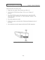
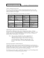
Polaroid CS-500i Color Scanner Setup
1. Unpack the color scanner. (Do not connect any cables to it.)
2. Verify that the SCSI ID selector (Figure 2-28) is set to 4. Change it if
necessary.
3. Turn off the ID-4000 computer, then connect the power cord and the SCSI
cable to the scanner. (If necessary, see “Cable Connections” on page 2-51 for
wiring diagrams.)
4. Turn on the scanner power switch.
5. Calibrate the scanner as described in the Calibration and Adjustment section of
this manual.
6. After calibration, turn on the computer and the other ID-4000 components.
Figure 2-28. Color Scanner SCSI ID Selector
2-40
Section 2: System Configuration
Polaroid ID-4000 Service Manual
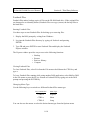
Magtek MT-80 Magnetic Stripe Encoder Setup
Connect the Magtek MT-80 magnetic stripe encoder to serial port 2 and set the switches
as appropriate for the installation. Remove the cover from the unit to access the switch
(Figure 2-29).
The standard default settings (shown in Figure 2-30) are 4800 baud, 1 stop bit and odd
parity.
Rate
110
150
300
600
1200
2400
4800
9600
Baud Rate
Sw 1 Sw 2 Sw 3
on
on
on
on
off
on
off
off
on
on
on
on
off
on
off
on
off
off
off
off
off
off
on
on
STX/ETX
Transmit
No transmit
Sw 7
on
off
Stop Bits Sw 4
1
on
2
off
Parity Bit Sw 5
Odd
on
Even
off
CR
Transmit CR
Transmit ETX
Note: Switches 6 and 9 are not used.
Figure 2-29. Magtek Encoder Switch Access
2-41
Sw 8
on
off
Section 2: System Configuration
Polaroid ID-4000 Service Manual
ON
OFF
n
n
n
n
1
2
3
n
n
n
4
5
6
7
n
n
8
9
Figure 2-30. Magtek MT-80 Default Switch Settings
(4800 Baud, 1 Stop Bit, Odd Parity)
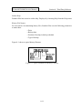
Laminator Setup
After turning the laminator on and waiting a few minutes for it to reach operating
temperature, check the thermometer (Figure 2-31). If it is not 275°F, turn the temperature
potentiometer in the appropriate direction with a small screwdriver. Wait a few minutes
for the temperature to stabilize, then recheck and adjust again if necessary.
Thermometer
Figure 2-31. Laminator Temperature Adjustment
2-42
Section 2: System Configuration
Polaroid ID-4000 Service Manual
Intermec 3000A Barcode Labeler Setup
Connect the Intermec bar code label printer to serial port 1 or 2.
The factory settings are 9600 baud, 1 stop bit, 7 data bits and even parity. If necessary,
other values can be set via the switch (Figure 2-32) on the rear of the printer and following
tables.
Baud
Rate Sw 1 Sw 2 Sw 3
110
on
on
on
150
on
on
off
300
on
off
on
600
on
off
off
1200 off
on
on
2400 off
on
off
4800 off
off
on
9600 off
off
off
Data
Bits Sw 7
7
off
8
on
Media Type Sw 8
Label
off
Continuous on
Resolution Sw 11
0.010 in.
off
0.005 in.
on
Parit Sw 4 Sw 5
y
Spac
on
on
e
Odd
on
off
Mark
Even
off
off
Self-Strip
Adapter
Use with
Use without
on
off
Stop
Bits Sw 6
1
off
2
on
Figure 2-32. Intermec Bar Code Label Printer Switch
2-43
Sw 12
off
on
Section 2: System Configuration
Polaroid ID-4000 Service Manual
Sony 610 Black and White Thermal Printer Setup
1. Unpack the printer and save all packing materials.
2. Verify that all switches are set as follows (the factory settings):
Contrast
Brightness
Front Panel
Center Thru/EE
Center Posi/Nega
Thru
Posi
Back Panel
GAMMA
II
DIP Switches Figure 2-33
D ADJ
Center
3. Connect the video cable (part # 1B8811B) to Video In on the printer. Connect
the other end to the video breakout cable attached to the Cardinal SNAPPlus
board in the ID-4000 computer.
Figure 2-33. DIP Switch Settings: Sony 610 Thermal Printer
Sony 860 Black and White Thermal Printer Setup
1. Unpack the printer and save all packing materials.
2. Set the switches on the back of the printer according to (Figure 2-34).
3. Connect the BNC end of the printer cable to the printer, and connect the 8-pin
mini M connector end of the cable to center connector of the Cardinal board in
the ID-4000 computer.
Figure 2-34. Switch Settings: Sony 860 Thermal Printer
2-44
Section 2: System Configuration
Polaroid ID-4000 Service Manual
Inforite Signature Tablet Setup
Connect the Inforite signature tablet to serial port 1, and connect the power cable (integral
with the tablet's serial connector) to AC power. No other settings are needed.
Note: The Inforite software is included in the ID-4000 application. Do
not install the Inforite software packaged with the tablet.
DataCard B&W PVC Printer (ImageCard I) Setup
Connect the DataCard black and white PVC printer (ImageCard I) to parallel port 1 or 2.
The DataCard PVC printer has no switches. The default configuration will be used from
the NOVRAM. Cabling is from a standard Centronics parallel port. Print control is set up
for roller cleaning, and upon startup the FAULT LED will flash rapidly to tell the operator
to insert a cleaning card.
If necessary, use the following tables to interpret the LEDs on the front of the printer.
Green (Center) LED
State
Off
Indication
Waiting for
command or
printing card
On-line, ready
On,
steady
Flashing Receiving data
slowly
Amber (Bottom) LED
Action
Required
State
Indication
None
Off
None
On,
Card jam
steady
Flashing Rollers require
rapidly
cleaning
(If green LED is
also flashing
rapidly,
checkerboard
card will be
printed)
None
Flashing Ready to print
Insert
rapidly
ID card
card
(If amber LED is
also flashing
rapidly,
checkerboard
card will be
printed)
No problem
Action
Required
None
Clear jam
Insert
cleaning
card
After connecting and configuring the printer, install the printer driver and edit ESMS.INI
as described in “DataCard Black and White PVC Printer Software Setup”on page 2-118.
2-45
Section 2: System Configuration
Polaroid ID-4000 Service Manual
DataCard Color PVC Printer (ImageCard II) Setup
Setting up the DataCard Color PVC (ImageCard II) printer requires these three
procedures:
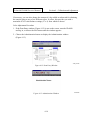
1. Unpacking, connecting and loading the printer.
2. Powering up and testing the printer.
3. Installing the printer driver.
Details of these procedures are given below.
Unpacking, Connecting and Loading the Printer
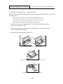
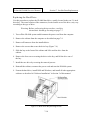
1. Unpack the printer and open the cover.
2. Remove any packing tape from inside the printer.
3. Loosen the four shipping screws securing the transport assembly (Figure 2-35).
Note: Do not remove the screws. Just loosen them until you feel a
slight resistance (1 to 1¼ turns).
4. Remove the card weight from the card input tray.
5. If the cards to be printed are not the normal thickness (0.030 in.), adjust the
card choke at the rear of the input hopper according to the Adjustments section
of the ImageCard II Maintenance Manual.
Figure 2-35. ImageCard II Shipping Screws
2-46
Section 2: System Configuration
Polaroid ID-4000 Service Manual
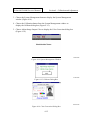
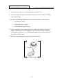
6. Turn the printer power switch to OFF (Figure 2-36) and turn off the ID-4000
computer.
7. Use a standard 25-pin M / 50-pin Centronics parallel cable to connect the
printer’s parallel connector (Figure 2-36) to the ID-4000 computer parallel port.
8. Follow instructions in the ImageCard II Printer Operator’s Guide to load print
ribbon, overlay foil, cleaning tape and blank PVC cards in the printer.
Figure 2-36. ImageCard II Power Switch and Parallel Cable Connection
Powering Up and Testing
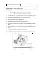
1. Open the printer cover.
2. Turn the printer power switch (Figure 2-36) to ON and verify the following
events:
a. Power indicator lights
b. From left to right, one at a time, all panel LCDs flash five times and turn
off
c. Transport assembly (Figure 2-35) moves to far right
d. Print head moves down and back up
e. Cleaning roller assembly initializes
f. Overlay foil advances
g. Transport assembly moves back to home position
h. Print ribbon advances
i. Ready LED lights (about 30 seconds after ribbon advances)
2-47
Section 2: System Configuration
Polaroid ID-4000 Service Manual
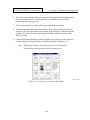
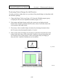
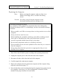
3. Press and hold the Ready key for about 3 seconds, then release it.
4. When the Card LED blinks, use the insertion slide to insert a blank card and
print a test pattern (Figure 2-37) on it.
5. Repeat steps 3 and 4 to print several cards.
6. Verify that all test cards have the following:
•
•
•
•
Dimensions shown in Figure 2-37
Complete print pattern with uniform pattern density
Correct color in each labeled color box
Freedom from streaks, lines and blemishes in the printed area
Note: If the cards do not meet these standards, refer to the
troubleshooting section of the ImageCard II Maintenance
Manual.
Installing the Printer Driver
After completing power-up and testing, and after setting up all the other input and output
devices on the ID-4000, install the ImageCard II printer driver as described on page 2119.
Figure 2-37. Test Card
2-48
Section 2: System Configuration
Polaroid ID-4000 Service Manual
AT&T Paradyne 14.4 FAX/Modem Setup
Connect the external AT&T Paradyne 14.4 fax/modem to serial port 2 with a 9-pin (F) /
25-pin (M) serial cable.
The fax/modem uses the following third-party software:
• Close-Up (for communications)
• WinFAX Pro (fax)
Installation procedures for Close-Up is on page 2-78. To install WinFAX, follow the
instructions provided with the software.
LaserJet IV Printer Setup
Cable Connection
Connect the HP LaserJet IV laser printer to any parallel port with a standard 25-pin M /
50-pin Centronics parallel cable.
Printer Driver Installation and Setup
Note: This procedure requires a diskette containing the Windows
driver for the LaserJet IV printer. The diskette is provided
with the printer.
1. Start Windows and open Control Panel in the Main program group.
2. Double-click the Printers icon to open the Printers dialog box.
3. Click the Add button, then click the Install button.
4. Insert the diskette containing the LaserJet IV driver into drive A. Click OK.
5. Highlight HP LaserJet 4/4M in the List of Printers and click OK.
6. Follow the on-screen instructions to finish installing the driver. Remove the
diskette from A-drive.
7. Click on the Setup button in the Printers dialog box and select 300 dpi from the
Printer Resolution box.
8. Click on the Options button and select Raster in the Graphics Mode box.
9. Make sure High is selected in the Graphics Quality box.
10. Continue clicking OK until you return to the Printers dialog box.
2-49
Section 2: System Configuration
Polaroid ID-4000 Service Manual
11. Click on Connect and choose the appropriate printer port.
12. Click on Close to finish set up and return to the Control Panel, then close the
Control Panel.
Hardware Key Installation and Setup
The following hardware key installation is required for all ID-4000 systems. If the key is
not installed, the message "Illegal Use of Polaroid Software" appears when the user
attempts to start ID-4000 applications.
Note: Installation requires an initialization software diskette,
provided with the key.
1. Connect the hardware key to LPT1 (parallel port 1). If necessary, disconnect
any device already attached to LPT1.
2. Connect any device normally attached to LPT1 (the LaserJet IV, for example)
to the hardware key instead.
Note: The Key is a pass-through device.
3. Insert the key initialization software diskette into drive A and run the
initialization program according to instructions provided with the key. Then
remove the diskette from the drive.
4. Start the ID-4000 application to verify that the key is properly installed.
2-50
Section 2: System Configuration
Polaroid ID-4000 Service Manual
Cable Connections
Cabling information for some typical ID-4000 systems and their components is provided
below. Because of ID-4000 component flexibility, cable configurations can vary from
those shown here.
System Cabling
The system cabling diagrams on the following pages represent three typical ID-4000
configurations. ID-4000 systems using computers other than the NCR 3333 may have
boards and connectors arranged differently from those shown in the diagrams.
CPU, Input and Output Devices
ID Card Printer
Cable Diagram
• NCR 3333 computer, monitor, CI-5000S color film
keyboard, mouse
recorder
Figure 238
Page 2-52
• Input unit
• Signature tablet
TX-1500 color thermal
printer
Figure 239
Page 2-53
• Modem
• HP LaserJet printer
TX-2000 (VY-300)
color thermal printer
Figure 240
Page 2-54
2-51
Section 2: System Configuration
Polaroid ID-4000 Service Manual
Figure 2-38. Cabling Diagram: ID-4000 with CI-5000S Film Recorder
2-52
Section 2: System Configuration
Polaroid ID-4000 Service Manual
Figure 2-39. Cabling Diagram: ID-4000 with TX-1500 Thermal Printer
2-53
Section 2: System Configuration
Polaroid ID-4000 Service Manual
Figure 2-40. Cabling Diagram: ID-4000 with TX-2000 (VY-300) Thermal Printer
2-54
Section 2: System Configuration
Polaroid ID-4000 Service Manual
SCSI Device Address Organization
For the NCR system utilizing the 850M SCSI card, the ID addressing is as follows:
SCSI
ID
0
1
2
3
4
5
6
7
Device
Spare
Spare
CI-5000 Plus color film recorder
Spare
CS-500i color scanner
Spare
Archive Viper tape drive
Reserved for Future Domain TMC850M SCSI controller
SCSI Disk Tape, CI-5000 Plus and CS-500i Cabling
Note: You MUST terminate at both ends of the SCSI line, and
ONLY the ends.
Example: The ID-4000 computer has an internal SCSI hard
disk and a tape unit. Both are driven from the same SCSI
board on the same cable. The hard drive is at the end of the
cable and the tape drive is in the center of the cable. In this
case, the terminating resistors in the tape drive must be
removed and the resistors in the hard drive must be installed
(left in place).
If a SCSI device is attached to the rear panel external connector, the terminating resistors
on the SCSI card must be removed. If no external SCSI device is installed, the terminating
resistors on the SCSI board must be left installed. In the case of an optical drive connected
to the SCSI board rear panel connector, the resistors on the SCSI card would be removed
and the resistors inside the optical drive would be installed (left in place).
Warning: Turn off ALL power (both to computer and to the
SCSI devices) before you unplug a SCSI cable.
2-55
Section 2: System Configuration
Polaroid ID-4000 Service Manual
SCSI Board Configuration
1. Remove the terminating resistors on the SCSI board.
2. If you have a single SCSI device on a multiple device cable, make sure the
device is plugged into the end of the 50-pin SCSI cable.
Note: The red stripe on the cable indicates pin 1. Be sure to connect
it to pin 1 of the SCSI device and the SCSI board. SCSI
connectors are not usually keyed and can be connected
incorrectly.
SCSI Cabling with 850m Controller Board
SCSI cabling options for ID-4000 systems using the 850m controller board and the CI5000 Plus color film recorder are shown in Figure 2-41. Options for the 850m controller
board and the TX-1500 or TX-2000 (VY-300) color thermal printer are shown in Figure
2-42.
50 Pin Terminator
CPU
CI-5000+
25 to 50 Pin Cable
SCSI ID=2
50 Pin Terminator
CPU
25 to 25 Pin Cable
CS-500i
25 to 50 Pin Cable
CI-5000+
SCSI ID=2
SCSI ID=4
Figure 2-41. SCSI Cabling: 850m Controller Board and CI-5000 Film Recorder
25 Pin Terminator
CPU
25 Pin Terminator
CPU
CS-500i
25 to 25 Pin Cable
SCSI ID=4
Figure 2-42. SCSI Cabling: 850m Controller Board and Color Thermal Printers
2-56
Section 2: System Configuration
Polaroid ID-4000 Service Manual
Magnetic Stripe Encoder Cabling
The following magnetic stripe encoders are available for the ID-4000:
•
•
•
•
Magtek MT-80 Low Coercivity
Magtek MT-80 High Coercivity
Elcom A80ER-RS
Elcom A4ER-RS
Note: MT-80 and A80ER-RS require a null modem cable.
A4ER-RS requires a regular pass-through serial cable.
The magnetic stripe encoder connects to any serial port on the ID-4000 computer, as
shown in Figure 2-43.
CPU
9 to 25 Pin Cable
Magnetic
Stripe
Encoder
Figure 2-43. Magnetic Stripe Encoder Cabling
The cable pin outs for the magnetic stripe encoder cable are as follows:
Designation
Pin No.,
CPU
Pin No.,
Encoder
GND
TD
RD
RTS
CTS
DSR
GND
DTR
1
2
3
4
5
6
7
20
1
3
2
5
4
20
7
6
2-57
Section 2: System Configuration
Polaroid ID-4000 Service Manual
Intermec 3000A Barcode Labeler Cabling
The Intermec 3000A bar code labeler connects to any serial port on the ID-4000
computer, as shown in Figure 2-44.
CPU
9 to 25 Pin Cable
Intermec
Labeler
Figure 2-44. Bar Code Labeler Cabling
The cable pin outs for the Intermec 3000A bar code labeler cable are as follows:
Designation
Pin No.,
CPU
Pin No.,
Labeler
GND
TD
RD
RTS
CTS
DSR
GND
1
2
3
4
5
6
7
1
3
2
5
4
20
7
DataCard Black and White PVC Printer Cabling
Connect the DataCard black and white PVC printer to any parallel port as shown in Figure
2-45.
CPU
25 to 25 Pin Cable
DataCard
Printer
Figure 2-45. DataCard Black and White PVC Printer Cabling
2-58
Section 2: System Configuration
Polaroid ID-4000 Service Manual
Cable pin outs for the PVC printer's 25-pin female D-subminiature connector are as
follows:
Pin
No.
1
2
3
4
5
6
7
8
9
Pin
Pin
Designation Direction No. Designation Direction No. Designation Direction
Data Strobe
in
10 Acknowledge out
19 Gnd
in
Data Bit 1
in
11 Busy
out
20 Gnd
in
Data Bit 2
in
12 Paper End
out
21 Gnd
in
Data Bit 3
in
13 Select
out
22 Gnd
in
Data Bit 4
in
14 Auto Feed
in
23 Gnd
in
Data Bit 5
in
15 Error
out
24 Gnd
in
Data Bit 6
in
16 Initiate
in
25 Gnd
in
Data Bit 7
in
17 Select In
in
Data Bit 8
in
18 Gnd
in
TX-2000 (VY-300) Color Thermal Printer Cabling
Connect the Polaroid TX-2000 (Hitachi VY-300) color thermal printer to parallel port 1 or
2 with a standard parallel cable (25-pin D-sub to 36 pin Centronics) as shown in Figure 246.
CPU
25 to 36 Pin Cable
TX-2000
(VY-300)
Printer
Figure 2-46. TX-2000 (VY-300) Color Thermal Printer Cabling
The pin outs for the 25 pin female D-subminiature to 36 pin male Centronics are as
follows:
Pin
No.
1
2
3
4
5
6
7
8
9
Pin
Pin
Designation Direction No. Designation Direction No. Designation Direction
Data Strobe
in
10 Acknowledge out
19 Gnd
in
Data Bit 1
in
11 Busy
out
20 Gnd
in
Data Bit 2
in
12 Paper End
out
21 Gnd
in
Data Bit 3
in
13 Select
out
22 Gnd
in
Data Bit 4
in
14 Auto Feed
in
23 Gnd
in
Data Bit 5
in
15 Error
out
24 Gnd
in
Data Bit 6
in
16 Initiate
in
25 Gnd
in
Data Bit 7
in
17 Select In
in
Data Bit 8
in
18 Gnd
in
2-59
Section 2: System Configuration
Polaroid ID-4000 Service Manual
Cabling Options with Cardinal and Support Boards
When the ID-4000 computer has both the Cardinal board and the support board, configure
cabling according to the appropriate diagram in Figure 2-47.
25 to 25 Pin Cable
(Support Bd. Cable)
Input Unit
CPU
25 Pin M to
50 Pin Centronix
CI-5000
8 Pin Mini Din
(Cardinal Board Video In)
Cardinal and Support Boards with CI-5000
8 Pin Mini Din
to 4 BNC
25 to 25 Pin Cable
(Support Bd. Cable)
Input Unit
CPU
8 Pin Mini Din
(Cardinal Board Video In)
Cardinal Board
Video Out
TX-1500
Cardinal and Support Boards with TX-1500
Input Unit
25 to 25 Pin Cable
(Support Bd. Cable)
CPU
25 Pin to 36 Pin
Centronix
TX-2000
8 Pin Mini Din
(Cardinal Board Video In)
Cardinal and Support Boards with TX-2000
25 Pin M/to 8 Pin Mini Din
CPU
8 Pin Mini Din to 4 BNC
(Cardinal Board Video Out)
TX-1500
Cardinal and Support Boards with TX-1500 (Standalone)
25 Pin Male to 36 Pin Centronix
CPU
(Does not use Cardinal Board)
TX-2000
Cardinal and Support Boards with TX-2000 (Standalone)
BNC to BNC
Input Unit
Fingerprint
Unit
25 to 25 Pin Cable
(Support Bd. Cable)
8 Pin Din to 4 BNC
CPU
TX-1500
8 Pin Mini Din
(Cardinal Board Video In)
Cardinal and Support Boards on DMV I/O System
Figure 2-47. Cabling Options for Cardinal and Support Boards
2-60
Section 2: System Configuration
Polaroid ID-4000 Service Manual
Software Installation and Setup
Software Elements
ID-4000 software installation includes the following items:
•
•
•
•
•
•
•
DOS 6.XX
Cardinal board driver for Windows
ID-4000 application software (ID-4000 Application Builder and the ID4000 application)
Close-Up
Third-party database application (dBase, SQLbase, etc.)
FastBack
Crystal Reports
Software Installation Overview
Installing ID-4000 software consists of the following general steps:
1. Configure the computer CMOS, if necessary.
2. Format the hard disk, if necessary.
2. Install DOS, if necessary.
3. Install Windows, if necessary.
4. Install the mouse driver
5. Install the Cardinal display driver.
6. Install the applicable third party software (FastBack, Crystal Reports,
CloseUp, bar code fonts).
7. Install the SQL Local database application.
8. Install the SQL LAN (Novell) database application.
9. Install the ID-4000 application software.
Refer to the remainder of this chapter for detailed information about each of these steps.
Software Installation: NCR 3333
Installing the software on the NCR 3333 system consists of two separate procedures:
1. Configuring the CMOS.
2. Installing the software.
2-61
Section 2: System Configuration
Polaroid ID-4000 Service Manual
Configuring the NCR 3333 CMOS
1. Reboot the computer by simultaneously pressing CONTROL, ALT and
DELETE.
2. During initialization, press F1 to display the CMOS setup screen (Figure 2-48).
3. Verify that the settings are as shown in Figure 2-48, and change any settings
that do not match the figure.
4. Select Software Controlled Registers by pressing F2. The Software Controlled
Registers screen appears (Figure 2-49).
Figure 2-48. NCR 3333 CMOS Setup Screen
Figure 2-49. Software Controlled Registers Screen
2-62
Section 2: System Configuration
Polaroid ID-4000 Service Manual
5. If shadow video BIOS is disabled (set to No), skip to step 6.
If shadow video BIOS is enabled (set to Yes), disable it as follows:
a. Select Shadow Video Bios.
b. Select 0=No (Disable).
c. Press ENTER.
6. Press END to return to the CMOS Setup screen.
7. Press END to save the setup parameters and exit to the DOS prompt.
8. Reboot the system by simultaneously pressing CONTROL, ALT and DELETE.
After configuring the CMOS, proceed to “Installing the Software” below.
Installing the Software on the NCR 3333 System
1. If necessary, format the hard disk and install DOS as described on page 2-74.
2. Install or configure the following software as appropriate for the system:
Installation
or Config.
Instructions
Software
Install Windows
Page 2-76
Mouse driver
2-77
Cardinal SnapPlus Windows driver
2-78
Close-Up
2-78
Crystal Reports
2-80
FastBack PLUS
2-80
DOS/Windows SQLBase server
2-82
SQL LAN database software
2-84
3Com 3c509 Combo Ethernet configuration
2-105
Bar code fonts
2-106
ID-4000 core software
2-107
ESMS.INI and AOI.INI for multiple area of
interest scanning
2-112
Time and date format
2-108
2-63
Section 2: System Configuration
Polaroid ID-4000 Service Manual
Installation
or Config.
Instructions
Software
SQLBase isolation level settings
2-108
Oracle DLL file names
2-109
PowerSCSI for tape drives
2-111
PVC printer software
2-118
Software Installation: HP Vectra VL2 4/50
After setting up the input and output devices and connecting the cables, use the following
steps to install the software on the HP Vectra VL2 4/50 computer:
1. Power up the computer.
2. Delete the Windows directory from the hard drive by typing deltree
c:\windows and confirming your action.
3. Install Windows as described on page 2-76.
4. Reboot the system so changes take effect.
5. Edit AUTOEXEC.BAT to change the line C:\WINDOWS\SMARTDRV.EXE
to C:\DOS\SMARTDRV /X.
6. Add the following two lines to the [386Enh] section of SYSTEM.INI (in the
C:\WINDOWS directory):
COM1FIFO=0
COM2FIFO=0
7. Reboot the system.
8. In the Windows Program Manager, delete the Applications group.
9. Install Plug and Play by inserting the Plug and Play Diskette into drive A, then
using the Windows Run command to run a:\setup.
10. Exit from Windows, log into the C:\WINDOWS directory, and start Windows
setup by typing setup and pressing ENTER.
11. Change the Computer setting to MS-DOS System with APM, then save the
setup.
2-64
Section 2: System Configuration
Polaroid ID-4000 Service Manual
12. Modify SYSTEM.INI by adding the following lines:
[POWER.DRV]
Powerstatus=0
13. Start Windows.
12. Insert the Advanced Power Management Disk into drive A, then use the
Windows Run command to run a:\power\anstapm.exe US.
13. Install SLEEP.EXE in the Windows Startup group as follows:
a. Open Windows Startup Group
b. Pull down the Program Manager File menu and select New.
c. Select Program Item.
d. Use the Browse button to select SLEEP.EXE from the Windows
directory.
e. Choose OK to insert display SLEEP.EXE in the Startup group.
f. Close the Startup group and exit from Windows.
14. If C:\CONFIG.SYS does not contain the following line, add it:
Device=C:\DOS\POWER.exe ADV:MAX
15. Reboot the system.
16. Install the Colorado Trakker advanced software as follows:
a. Insert the Colorado Trakker advanced software diskette in drive A and
log onto drive A.
b. Type a:setup and press ENTER.
c. Choose Colorado Trakker.
d. From the Options menu, choose Preferences.
e. Choose Software Compression for Speed.
f. Follow on-screen instructions to save the settings and exit from the
setup program.
2-65
Section 2: System Configuration
Polaroid ID-4000 Service Manual
g. Test the Trakker drive for proper operation.
Note: The Trakker drive does not support ID-4000 import or export
for text data or for text and images (import/export, data
transport).
17. Install or configure the following software as appropriate for the system:
Installation
or Config.
Instruction
s
Software
Mouse driver
2-77
Cardinal SnapPlus Windows driver
2-78
Close-Up
2-78
Crystal Reports
2-80
FastBack PLUS
2-80
DOS/Windows SQLBase server
2-82
SQL LAN database software
2-84
3Com 3c509 Combo Ethernet configuration
2-105
Bar code fonts
2-106
ID-4000 core software
2-107
ESMS.INI and AOI.INI for multiple area of
interest scanning
2-112
Time and date format
2-108
SQLBase isolation level settings
2-108
Oracle DLL file names
2-109
PowerSCSI for tape drives
2-111
PVC printer software
2-118
18. Edit AUTOEXEC.BAT as follows:
a. Change the line SET TEMP=C:\WINDOWS\TEMP to
SET TEMP=C:\DOS.
b. Delete the line C:\WINDOWS\SETRES\CLMODE M0.
c. Delete the extra REM’s from the file.
d. Move the line WIN to the end of the file.
2-66
Section 2: System Configuration
Polaroid ID-4000 Service Manual
19. If the system contains a 3C509B-C Ethernet card, perform the following steps.
If it does not contain this Enternet card, go to step 20.
a. Reboot the system.
b. Connect the Ethernet cable to the card to allow proper operation of the
configuration program.
c. Edit CONFIG.SYS to REM out the line containing DWCFGMG.SYS (a
Plug and Play driver).
d. Insert the disk supplied with Ethernet card into drive A and log onto the
A drive.
e. Type menu and press ENTER.
f. Select Y.
g. Select Netware DOS ODI Client.
h. Select Y to return to the menus.
i. Select Configuration/Diagnostic/Troublshooting.
j. Select Configuration & Diagnostic Program.
k. Select Install then Configure adapter.
l. Select Auto Configure.
m. When a message indicates that configuration is complete, select OK.
n. Select Test, then select Run Tests & Start.
o. When a message indicates that the tests are finished, press ENTER.
p. Select Quit & Exit.
q. Edit the Link Driver section of NET.CFG (in the C:\NWCLIENT
directory) as follows:
(1) Change 3C589 to 3C5x9.
(2) Remove the semicolon (;) from the line containing 300.
(3) Change 802.2 to 802.3.
2-67
Section 2: System Configuration
Polaroid ID-4000 Service Manual
20. Reboot the system to complete the software installation.
When the software installation is complete, proceed to “System Calibration” on page 2-82
and “Functional Check” on page 2-120.
Software Installation: CSS 462 486 ESP-M
After setting up the input and output devices and connecting the cables, use the following
steps to install the software on the CSS 462 486 ESP-M computer:
1. Power up the system.
2. Initialize the mouse driver for COM2 by logging into C:\MOUSE (type cd
\mouse and press ENTER) and running MOUSE.COM (type mouse and press
ENTER).
3. Log into the Windows directory (type cd \windows and press ENTER) and run
SETUP (type setup and press ENTER).
4. Select Display from the System Information list.
5. Select Other from the list of display types. (Other is usually at the bottom of the
list, requiring you to use the Down arrow to reach it.)
6. Select ET4000 640 x 480 32768.
7. Choose Accept Configuration to return to the DOS prompt.
8. Start Windows by typing win and pressing ENTER.
9. Minimize the Cirrus Logic Utilities window, then delete it by pressing the
DELETE key and choosing Yes to confirm your action.
10. Install the following software as appropriate for the system:
Installation
or Config.
Instructions
Software
Cardinal SnapPlus Windows driver
Close-Up
Crystal Reports
FastBack PLUS
DOS/Windows SQLBase server
SQL LAN database software
2-68
2-78
2-78
2-80
2-80
2-82
2-84
Section 2: System Configuration
Polaroid ID-4000 Service Manual
Installation
or Config.
Instructions
Software
3Com 3c509 Combo Ethernet configuration
2-105
Bar code fonts
2-106
ID-4000 core software
2-107
ESMS.INI and AOI.INI for multiple area of
interest scanning
2-112
Time and date format
2-108
SQLBase isolation level settings
2-108
Oracle DLL file names
2-109
PowerSCSI for tape drives
2-111
PVC printer software
2-118
When the software installation is complete, proceed to “System Calibration” on page 2120 and “Functional Check” on page 2-120.
Installing the CSS 462 IDE/IO Device Driver
If the IDE/IO device driver on the CSS 462 486 ESP-M computer becomes accidentally
disabled or deleted, reinstall it by running VLIDE.EXE on the Promise PDC 20230 IDE
device driver diskette.
Software Installation: AT&T Globalyst
1. Power up the system.
2. When the setup screens appear, verify that the settings match the following
recommended values:
System Setup
Video System
Monitor Type
PS/2 Mouse
System Memory
[VGA or adapter] Extended Memory
[Type 0]
Diskette A
[Installed]
Diskette B
640 kb
7168 kb
[3.5” 1.44M Dr]
[Not Installed]
Fixed Disk Setup
Disk 0
Size
Cylinders
Heads
[Identify Drive]
515 Mb
1048
16
65535
0
63
WritePreComp
Landing Zone
Sectors
2-69
Section 2: System Configuration
Polaroid ID-4000 Service Manual
Power Management
System Standby
Hard Disk Standby
[Disabled]
[Disabled]
Performance Mode
[turbo mode (standard)]
Advanced System Setup: Cache Control
Internal Cache
[Enabled]
Second Level Cache
[Disabled]
ROM Cache F0000-FFFFF [Cacheable]
(BIOS)
Monitor Power Mgmt
Security Mode
[Disabled]
[Disabled]
ROM Cache C0000-C7FFF [Cacheable]
(Video)
Advanced System Setup: ROM Shadowing
F0000-FFFFF (System
[Enabled]
All other addresses
BIOS)
C0000-C7FFF (Video
[Enabled]
BIOS)
Chipset and Peripheral Control
Flex Disk Interface
[Enabled]
Primary AT Disk Interface [Enabled]
Secondary AT Disk Int.
[Disabled]
Parallel Port
[Enabled]
Serial Port 1
[Enabled]
User Password
Password Prompt
[On]
Boot Options
Keyboard Num Lock
Disketteless Operation
Displayless Operation
Keyboardless Operation
[On]
[Disabled]
[Disabled]
[Disabled]
ISA Legacy Resources
Do not change
[Disabled]
Serial Port 2
Bus Speed
Parallel Port Bidirectional
ECP
[Enabled]
[Standard]
[Disabled]
[Disabled]
Administrator Password
Allow user to change User [No]
Pswd
Boot Sequence
Virus Detection
[Drive A, then
Drive C]
[Enabled]
3. If necessary, format the hard disk and install DOS as described on page 2-74.
4. Install or configure the following software as appropriate for the system:
Installation
or Config.
Instructions
Software
Install Windows
Page 2-76
Mouse driver
2-77
Cardinal SnapPlus Windows driver
2-78
Close-Up
2-78
Crystal Reports
2-80
2-70
Section 2: System Configuration
Polaroid ID-4000 Service Manual
Installation
or Config.
Instructions
Software
FastBack PLUS
2-80
DOS/Windows SQLBase server
2-82
SQL LAN database software
2-84
3Com 3c509 Combo Ethernet configuration
2-105
Bar code fonts
2-106
ID-4000 core software
2-107
ESMS.INI and AOI.INI for multiple area of
interest scanning
2-112
Time and date format
2-108
SQLBase isolation level settings
2-108
Oracle DLL file names
2-109
PowerSCSI for tape drives
2-111
PVC printer software
2-118
Software Installation: IBM ValuePoint 6482
1. Power up the system.
2. When the setup screens appear, verify that the settings match the following
recommended values:
System Information
Processor
Processor Speed
Math Coprocessor
80486DX2
66 MHz
Installed
System Memory
Flash EEPROM Revision
Level
16000 KB
LDET64AUS
Video
Video Controller
Video Memory
Video Display Type
Horizontal Frequency
Refresh Rate 640x480
S3 Inc. Vision 864
1024 KB
[User Defined]
[31.5-36.9 KHz]
60 Hz
Refresh Rate 800x600
Refresh Rate 1024x768
Refresh Rate 1280x1024
Refresh Rate 1600x1200
56 Hz
43 Hz Interlaced
45 Hz Interlaced
Not Supported
Security
Power-on Password
Adminstrator Password
[Disabled]
[Disabled]
Diskette Drive Access
Hard Disk Access
[Enabled]
[Enabled]
2-71
Section 2: System Configuration
Polaroid ID-4000 Service Manual
Keyboard and Mouse
Keyboard Speed
Keyboard Numlock State
[Normal]
[On]
Input/Output Ports
Serial Port A
Serial Port B
[3F8-IRQ4] COM1 Parallel Port
[2F8-IRQ4] COM2 Parallel Port Mode
[3BC-IRQ7] LPT1
[PC/AT Compatible]
Cache
Internal Cache
8 KB [Enabled]
External Cache
128 KB [Enabled]
Mass Storage Devices
Diskette Drive 0
[1.44 MB 3.5”]
Primary IDE Mode
Diskette Drive 1
Not installed
Secodary IDE Mode
[High
Performance]
[High
Performance]
Hard Disk 0
539 MB (IDE)
Startup Options
First Startup Device
Second Startup Device
[Diskette Drive 0] Unattended Start Mode
[Hard Disk 0]
Disabled
Power Management
Power Down Timer
Processor
[30 Minutes]
[Managed]
Video Display
Hard Disks
[Not Managed]
[Managed]
Interrupts
IRQ5
IRQ10
[Available]
[Available]
IRQ11
[Available]
Memory Map (C0000-DFFFF)
System Video Bios at (C0000-C7FFF)
Memory Space at
(C8000-C9FFF)
Memory Space at
(CA000-CBFFF)
Memory Space at
(CC000-CDFFF)
Memory Space at
(CE000-CFFFF)
Memory Space at
Memory Space at
Memory Space at
Memory Space at
Memory Space at
Memory Space at
Memory Space at
Memory Space at
Internal Caching at
(D0000-D1FFF)
(D2000-D3FFF)
(D4000-D5FFF)
(D6000-D7FFF)
(D8000-D9FFF)
(DA000-DBFFF)
(DC000-DDFFF)
(DE000-DFFFF)
(C0000-CFFFF)
Keyboardless Oper Mode
Mouse
[Disabled]
Installed
Shadowed
Reserved for ROM or
UMB
Reserved for ROM or
UMB
Reserved for ROM or
UMB
Reserved for ROM or
UMB
[Available]
[Available]
[Available]
[Available]
[Available]
[Available]
[Available]
[Available]
[Enabled]
3. If necessary, format the hard disk, install DOS (page 2-74), and install
Windows (page 2-76).
2-72
Section 2: System Configuration
Polaroid ID-4000 Service Manual
4. Use Microsoft Diagnostics (MSD.EXE) to verify that the BIOS is version 0.02
dated 12/16/94 and that the flash EEPROM revision level is LDET64AUS.
If the flash BIOS is not the correct version, update the flash ROM with the
update diskettes provided with the computer.
Warning: Loss of power during BIOS update will disable the
main system board and require it to be replaced. If
possible, connect the computer to an
uninterruptible power supply before updating the
BIOS.
5. Follow on-screen instructions to register the software at the first boot-up.
6. Run QAPlus from Windows (in the ValuePoint Tools program group) to verify
correct system operation.
7. Use the Diskette Factory (in the ValuePoint Tools program group) to make
customer diskettes.
8. Open Windows Setup in the Main program group and change the video mode
to VGA.
9. Install or configure the following software as appropriate for the system:
Installation
or Config.
Instructions
Software
Mouse driver
Page 2-77
Cardinal SnapPlus Windows driver
2-78
Close-Up
2-78
Crystal Reports
2-80
FastBack PLUS
2-80
DOS/Windows SQLBase server
2-82
SQL LAN database software
2-84
3Com 3c509 Combo Ethernet configuration
2-105
Bar code fonts
2-106
ID-4000 core software
2-107
ESMS.INI and AOI.INI for multiple area of
interest scanning
2-112
2-73
Section 2: System Configuration
Polaroid ID-4000 Service Manual
Installation
or Config.
Instructions
Software
Time and date format
2-108
SQLBase isolation level settings
2-108
Oracle DLL file names
2-109
PowerSCSI for tape drives
2-111
PVC printer software
2-118
Formatting the Hard Disk and Installing DOS
Use this procedure to format the hard disk under any of the following conditions:
•
•
•
New hard drive is being installed
System is being installed for the first time
Hard drive has existing partitions
If the hard drive is preformatted, use the procedure below. If the hard disk is unformatted,
use the procedure “Formatting an Unformatted Hard Disk” on page 2-75 instead.
Reformatting a Preformatted Hard Disk
Use the following steps to reformat a hard disk that has been formatted previously:
1. Insert the DOS diskette labeled "Disk 1: Setup" in drive A.
2. Reboot by simultaneously pressing CONTROL, ALT and DELETE.
3. Wait for the message, “Welcome to Setup.” Then press F3 twice to exit to the
A-prompt.
4. Using FDISK.EXE, delete all partitions and logical drives from the hard drive.
5. Using FDISK.EXE, partition the hard drive according to the following tables:
Local Systems with BLOB storage:
Drive
Size (MB) Partitions
Any
2
Partition Sizes (MB)
90, all remaining space
2-74
Section 2: System Configuration
Polaroid ID-4000 Service Manual
All other systems:
Drive Size
(MB)
Partitions
Partition
Sizes (MB)
120
1
120
170
1
170
340
2
90, 250
520
3
90, 250, 180
520
3
90, 250, 250, 150
6. Continue with "Formatting an Unformatted Hard Disk" in the next section.
Formatting an Unformatted Hard Disk
1. Use FORMAT.EXE to format all logical drives, and install the DOS system
and utility files in the partition indicated in the following tables.
Local Systems with BLOB storage:
Drive
Size (MB) Partitions
Any
2
Partition Sizes (MB)
90, all remaining space
Contents
Logical Drive C:
Logical Drive D:
System files
Database (BLOBs)
All other systems:
Drive
Size
(MB)
Partitions
Partition
Sizes (MB)
120
1
120
System files,
database,
images
170
1
170
System files,
database,
images
340
2
90, 250
System files
Database,
images
520
3
90, 250, 180
System files
Database
Images
520
3
90, 250, 250, 150 System files
Database
Images
Logical
Drive C:
Contents
Logical
Drive D:
Logical Drive
E:, F:, etc.
2. Use CHKDSK.EXE to verify correct setup of each drive. If CHKDSK reports
any errors, refer to the Microsoft DOS manual for corrective action.
2-75
Section 2: System Configuration
Polaroid ID-4000 Service Manual
3. Use SCANDISK.EXE to perform a surface scan of each drive. If SCANDISK
reports any errors, refer to the Microsoft DOS manual for corrective action.
4. Use LABEL.EXE to create a volume label for each drive.
Installing Windows 3.1
1. Reboot the system by simultaneously pressing CONTROL, ALT and DELETE.
2. Start Windows Setup as follows:
a. Insert Microsoft Windows Disk 1 into drive A.
b. Log onto drive A by typing a: and pressing ENTER.
c. Type setup and press ENTER to display the setup welcome screen.
3. Press ENTER to display the Express and Custom setup choices.
4. Choose Express.
5. Follow instructions on the screen for inserting the other Windows diskettes.
6. When the Windows Setup dialog box appears, enter ID-4000 for Windows in
the Name box, and enter Polaroid Corporation in the Company box.
7. Choose Continue and verify that you have entered the correct information.
8. Choose Continue and follow on-screen instructions until the Printer Installation
dialog box appears.
9. Choose Install from the dialog box and continue following on-screen
instructions.
10. When the Setup Applications dialog box appears, select the default MS-DOS
Editor and click OK.
11. When the Windows Setup Tutorial dialog box appears, choose Skip Tutorial.
12. When the Exit Windows Setup dialog box appears, remove the diskette from
drive A and click Reboot.
2-76
Section 2: System Configuration
Polaroid ID-4000 Service Manual
13. When the DOS prompt appears, verify that Windows starts correctly by typing
win and pressing ENTER.
Warning: Unless it is impossible to do otherwise, never
reboot from within Windows. Always exit from
Windows before rebooting.
Note: If the ID-4000 system has an IBM ValuePoint 466DX2/Dp
computer, do not enable 32-bit disk access in Windows.
Installing the Mouse Driver
1. Remove the write-protection from the mouse setup diskette and insert the
diskette in drive A.
2. If Windows is not running, start it by typing win at the DOS prompt and
pressing ENTER.
3. Pull down the Program Manager File menu and select Run.
4. Type a:\setup in the Run dialog box and click on OK to display the Mouse
Setup dialog box.
5. Click on Continue to display the User Information dialog box.
6. Enter ID-4000 for Windows and Polaroid in the appropriate locations.
7. Click on Continue to display the Mouse Setup dialog box, then click on
Continue to accept the default settings.
8. Remove the diskette from drive A, click on Restart, and click OK to reboot.
9. Start Windows by typing win at the DOS prompt and pressing ENTER.
10. Verify that the mouse is working properly.
2-77
Section 2: System Configuration
Polaroid ID-4000 Service Manual
Installing the Cardinal SnapPlus Windows Driver
1. If Windows is not running, start it by typing win at the DOS prompt and
pressing ENTER.
2. Open the Main program group and choose the Windows Setup icon.
3. When the Windows Setup dialog box appears, pull down the Options menu and
select Change System Settings.
4. Click on the down arrow on the right end of the Display box, then choose Other
Display from the drop-down list to display a dialog box with the message
"Insert disk with display driver... ."
5. Insert the Ver. 2.01 Cardinal Windows Drivers diskette into drive A, then click
on OK.
6. Select ET4000 640x480 32768 col.
7. Click OK, then click OK a second time.
8. Remove the Cardinal diskette from drive A and insert Microsoft Windows
diskette requested by the on-screen message.
9. Follow instructions on the screen, reinsert the Cardinal diskette when directed
to do so, and click on OK.
10. Click on Restart Windows, then wait for Windows to start again.
11. Remove the Cardinal diskette from drive A.
Installing Close-Up 5.0
1. Copy the Close-Up diskette serial number onto a piece of paper for later
reference.
2. Verify that the modem is connected to serial port 2 and the power switch is on.
3. Exit from Windows to display the C-prompt.
4. If the system uses network drivers, verify that they are loaded. Load the
drivers, if necessary.
5. Insert the Close-Up Host and Remote diskette in drive A.
6. Log onto the A-drive by typing a: and pressing ENTER.
2-78
Section 2: System Configuration
Polaroid ID-4000 Service Manual
7. Type cinstall and press ENTER, then select Continue by pressing ENTER
again.
8. Press ENTER as needed to accept the following defaults:
•
•
•
•
Color
DOS & WINDOWS
Host & Remote
C:\CloseUp Dir
9. Follow the on screen directions to enter the following data:
Prompt
Entry
Your Name
ID-4000 for Windows
Organization
Polaroid Corporation
Serial Number
Number from Close-Up diskette
10. Select AT&T Paradyne DM424 V.32 as the installed modem.
11. Allow the setup program to create Windows group and icon. Press ENTER to
select the default configuration.
12. Set the Video Mode to VGA.
13. Press ENTER to accept the configuration.
Note: It may require a few seconds for the system to test the
configuration and redisplay it.
14. Press ENTER to close the setup program and return to the C-prompt.
15. Start Windows and start Close-Up to verify proper operation.
2-79
Section 2: System Configuration
Polaroid ID-4000 Service Manual
Installing Crystal Reports Pro 3.0
Note: Aways install Crystal Reports before installing the ID-4000
core software.
1. Insert diskette 1 of Crystal Reports Professional Edition, Version 3.X, into
drive A.
2. If Windows is not running, start it by typing win at the DOS prompt and
pressing ENTER.
3. Pull down the Program Manager File menu and select Run.
4. Type a:\setup in the Run dialog box and click on OK.
5. Select the default directory (C:\CRW) and click on Continue.
6. Insert the other Crystal Reports diskettes when prompted.
7. When a message indicates that file installation is complete, click OK.
8. When the INI File Change dialog box appears, click Continue (with Change).
9. When the File Change dialog box appears, click Continue (with Change).
10. When the message “Would you like to create a new Crystal Reports Program
Group?” appears, click YES.
11. When the message “ODBC was installed” appears, click OK.
12. When the message “Would you like to view Read Me file?” appears, click NO
to complete the installation.
Installing FastBack PLUS 6.0
1. If the ID-4000 computer is an IBM ValuePoint 466DX2/Dp, edit CONFIG.SYS
to disable (“rem-out”) EMM386.EXE. Then exit from Windows and reboot.
2. Exit from Windows to display the C-prompt.
3. Insert FastBack PLUS disk 1 into drive A, then log onto the A-drive.
4. Type install and press ENTER, then press ENTER again to begin installation.
5. Select the default installation directory by pressing ENTER.
6. Select the default express menus by pressing ENTER.
2-80
Section 2: System Configuration
Polaroid ID-4000 Service Manual
7. When the message "Set up a user name" appears, select Yes by pressing
ENTER.
8. Type ID4000 and press ENTER.
9. Continue to the next screen by pressing ENTER.
10. When the message “Is a QIC Tape Drive installed?” appears, select NO and
press ENTER.
11. When the message “Do You Have Any SCSI Tape Drives Attached?” appears,
select YES and press ENTER.
12. When the message “Would you like to schedule automated backups?” appears,
select NO and press ENTER.
13. When the message “Load Scheduler?” appears, select NO and press ENTER.
14. When prompted to modify the files, select YES and press ENTER.
15. When the message “Do you want to view the READ ME file now?” appears,
select NO and press ENTER.
16. Press ENTER to copy the files.
17. Follow the on-screen instructions.
18. Press ENTER to begin the test.
19. Remove the diskette from drive A and press ENTER.
20. Follow the on-screen instructions to complete the installation.
21. If the ID-4000 computer is an IBM ValuePoint 466DX2/Dp, edit
CONFIG.SYS to enable EMM386.EXE. Then reboot the system.
2-81
Section 2: System Configuration
Polaroid ID-4000 Service Manual
DOS/Windows SQLBase Server Installation
This installation procedure is for local, standalone, SQLBase server databases only.
Note: To use SQL as the database, the ID-4000 system must be
configured for SQLBase database.
This procedure has two components: (1) installing the software, and (2) setting up the
database structure.
Installing the Software
1. If Windows is not running, start it by typing win at the DOS prompt and
pressing ENTER.
2. Pull down the Program Manager File menu and select Run.
3. Insert SQLBase Server for Windows diskette 1 into drive A.
4. Type a:\sbrsetup in the Run dialog box and click on OK to display the
SQLBase DataBase Server for Windows dialog box.
5. Choose Install SQLBase for Windows using Defaults.
6. Accept C:\GUPTA DIR by pressing ENTER.
7. Follow on-screen instructions for inserting the remaining SQLBase Server for
Windows diskettes.
8. At the next dialog box, click on Continue to modify the file.
9. Click on OK to save the new version of AUTOEXEC.BAT.
10. Skip the new release notes by clicking on No.
11. Exit from Windows to display the DOS prompt.
12. Remove the diskette from drive A.
13. Continue with "Setting Up the Database Structure" below.
2-82
Section 2: System Configuration
Polaroid ID-4000 Service Manual
Setting Up the Database Structure
The following procedure establishes the customer's database directory structure. To assure
that you use the identical structure and syntax in the Configuration Builder when
generating customer diskettes, record the structure used below on paper.
1. At the DOS prompt, create the directory ID4K by typing md id4k and pressing
ENTER.
2. Log into the new directory by typing cd id4k and pressing ENTER.
3. Create a new directory named CUSTOMER by typing md CUSTOMER and
pressing ENTER.
Note: CUSTOMER denotes the directory name used on the
customer's system. This name can be any valid directory
name, but the same name must be used in the Configuration
Builder when generating customer diskettes.
4. Log into the new directory by typing cd CUSTOMER and pressing ENTER.
5. Create a new directory named SDATA by typing md sdata and pressing ENTER.
6. Verify that the new directory has been created by logging into it. (Type cd
sdata and press ENTER.)
7. Log into the C:\GUPTA directory by typing cd \gupta and pressing ENTER.
8. Verify that DBXLOCAL is installed by typing dbxlocal and pressing ENTER.
9. Type sqltalk and press ENTER.
10. Accept [DEMO] as the database name by pressing ENTER.
11. Accept [SYSADM] as a user name by pressing ENTER.
12. Type sysadm as the password and press ENTER.
Note: In steps 13-15, use upper case and lower case characters
exactly as indicated. Each command ends with a space and
a semicolon (;).
13. Type SET dbdir c:\id4k\customer\sdata ; and press ENTER.
14. Type CREATE DATABASE SDATA ; and press ENTER.
2-83
Section 2: System Configuration
Polaroid ID-4000 Service Manual
15. End the SQLTALK session by typing EXIT ; and pressing ENTER.
16. Remove the diskette from drive A, then reboot to free memory by
simultaneously pressing CONTROL, ALT and DELETE.
17. Edit SQL.INI as follows:
a. Log into the C:\GUPTA directory by typing cd \gupta and pressing
ENTER.
b. Open SQL.INI with the DOS editor by typing edit sql.ini and pressing
ENTER.
c. Scroll to the [dbwindow] section of SQL.INI, and add the following line:
dbdir=c:\id4k\customer\sdata
d. Scroll to the [dbwservr] section of SQL.INI, and add the following lines:
SERVERNAME=SERVER1
DBDIR=C:\ID4K\CUSTOMER\SDATA
e. Save the changes to SQL.INI by pulling down the File menu and
choosing Save.
f. Return to the DOS prompt by pulling down the File menu and choosing
Exit.
18. Reboot by simultaneously pressing CONTROL, ALT and DELETE.
Gupta SQLBase Server Installation on Novell Netware Server
Installing on the Server
Use this procedure for installing Gupta SQLBase Server from floppy diskettes to a Novell
Netware server (3.1x).
Note: Use only version 5.1.4 Netware diskettes.
These instructions are specifically for a Netware 5 user (3 diskettes), using the file server
ELVIS and installing on volume VOL3 as the drive J in the directory \SQLBASE using
SERVER3. Make the appropriate changes for the installation you are performing.
1. If you are in Windows, exit to DOS. (Do not attempt to use a Windows DOS
session.)
2-84
Section 2: System Configuration
Polaroid ID-4000 Service Manual
2. Log in as supervisor on the Novell Netware file server (ELVIS for these
instructions).
3. Verify that the volume you are installing on is mapped and you know the drive
letter to which it is mapped. (For these instructions, the volume is VOL3, and it
is mapped to drive letter J.)
4. Insert the first Netware diskette in drive A, log onto drive A, and run
DOSSETUP.EXE.
5. Follow the on-screen instructions to install only the server side component and
the DEMO database on drive J and in the directory \SQLBASE.
6. Follow the on-screen instructions for inserting the remaining diskettes in drive
A, which completes installation of the server software.
7. Make a backup of SQL.INI by copying it to SQLOLD.INI.
8. Edit SQL.INI as follows:
a. Delete the end-of-file character.
b. In the [Netware] section, enter the location of the files and the server
name with the appropriate protocol. For the example used in these
instructions, enter the following:
[dbnserver]
servername=server3,splspx
dbdir=vol3:\sqlbase
[dbn5srvr]
servername=server3,sqlspx
dbdir=vol3:\sqlbase
SQLBase wants serverX where X must be within the range 1-8. A
maximum of eight active databases are allowed on the same backbone
at any time. The name in the local copy of SQL.INI must be the same as
in the network version of SQL.INI.
9. On the server console (or from RCONSOLE), do the following:
a. Make sure CLIB and MATHLIB are already loaded:
load clib
load mathlib
2-85
Section 2: System Configuration
Polaroid ID-4000 Service Manual
b. Add the volume/directory to the search path:
search add vol3:\sqlbase
c. Load DIRECTFS, DFD, DLL, SPXDLL, and DBN5SRVR:
load directfs
load dfd
load dll
load spxdll
load dbn5srvr
Installing Client Components on the Workstation
The client software pieces necessary for communicating with SQLBase on the Novell
Netware Server are:
• Communications software (IPX/SPX and ODI)
• SQLBase client diskettes (two disks: SQLBase 5.1.4 DOS SQLBase Windows
Workstation Client Components)
1. Run A:\SETUP from within the Windows Program Manager.
2. Choose Custom, and choose Just the Client Software.
3. Follow on-screen instructions for inserting disk 2.
4. Edit SQL.INI as follows:
a. Delete the EOF character from the end of the file.
b. In the [winclient.dll] section, uncomment the line comdll=sqlspxw.
c. Verify that these lines are in the [dbnserver] and [dbn5srvr] sections:
dbdir=vol3:\sqlbase
servername=server3
Also note the following:
• SQLBase wants serverX where X must be within the range 1-8.
• You can only have up to 8 active databases on the same backbone at any one time.
• The name in the local copy of SQL.INI must be the same as in the network version of
SQL.INI. (This information may be obtained from the system administrator.)
2-86
Section 2: System Configuration
Polaroid ID-4000 Service Manual
Client Software Installation for Oracle on SCO UNIX Server
The client software pieces necessary for communicating with oracle on the UNIX Server
are:
• Communications software (PC-TCP)
• SQL*Net TCP/IP
• Four diskettes for Oracle Client Software:
• SQL*Net TCP/IP Version 1.1 Windows
• Install V3.0.9.5.1 (1 disk)
• Required Support Files V7.0.15.0.0D (2 disks)
• SQL*Net TCP/IP V1.1.7.8 (1 disk)
1. Install the Oracle Installer (the program from which all other Oracle products
are installed onto the client system) as follows:
a. Insert the Oracle Windows Install Disk and run A:\ORAINST.EXE from
the Windows Program Manager.
b. Choose English and Click Select in the Language dialog box.
c. Enter ID-4000 and Click OK in the Customer Name dialog box.
d. Click OK to accept C:\ORAWIN in the Set Oracle Home dialog box.
e. Click Yes to allow Install to modify AUTOEXEC.BAT
f. Click OK in the Notification dialog box about rebooting.
g. Exit from Windows, reboot and restart Windows.
2. Install the support files as follows:
a. Insert disk 1 of the Required Support files into drive A.
b. Double Click on the Oracle Installer.
c. Click Install... with Required Support Files highlighted.
d. Insert disk 2 of the Required Support files when requested, and follow
on-screen instructions to complete installation of the support files.
Note: After installing Required Support files, do not exit from the
Oracle Installer.
3. Install Oracle TCP/IP as follows:
2-87
Section 2: System Configuration
Polaroid ID-4000 Service Manual
a. Insert the SQL*Net TCP/IP diskette into Drive A.
b. From within the Oracle Installer, click From...
c. Click Install.. with SQL*Net TCP/IP highlighted.
d. Choose FTP PC/TCP 2.2 via Winsock and Click Select in the Vendors
dialog box.
e. Click OK to acknowledge installation of JSB files in the JSB files
dialog box.
f. Click OK to allow Install to add TCP_VENDOR to ORACLE.INI in the
Vendor strings dialog box.
g. Click OK to agree that the services file is located at
C:\PCTCP\SERVICES in the Services file dialog box.
h. Click OK to accept sample file containing ORASRV port number for
the services file int TCP_SERVICES_FILE dialog box.
i. Click File/Exit to exit from the Oracle Installer.
4. Test the Oracle connection as follows:
a. From the Windows Program Manager, run
C:\ORAWIN\BIN\NETTEST.EXE.
b. Click Oracle/Connect.
c. Enter the following parameters, then click OK.
User ID:
system
Password:
oracle
Connect String: t:fuzzball:test
d. If the message “Logon Successful” does not appear, recheck the
configuration for proper setup.
e. Disconnect by choosing Exit and waiting for the message “Disconnect
Successful.”
2-88
Section 2: System Configuration
Polaroid ID-4000 Service Manual
Client Software Installation for Oracle on NetWare Server
The client software pieces necessary for communicating with oracle on the Novell
Netware Server are:
• Communications software (IPX/SPX and ODI)
• SQL*Net SPX
• 3 Disks for Oracle Client Software (Oracle7 Server for Netware. Version 7.0):
•
•
•
Windows Install V3.0.8.3.7
Windows Required Support Files V7.0.12.1.0
Windows SQL*Net SPX V1.1.1.5
1. Install the Oracle Installer by inserting the Oracle Windows Install diskette in
drive A and running A:\SETUP.EXE from the Windows Program Manager.
2. Insert the Windows Required Support Files diskette in drive A, click From,
then click Install.
3. Insert the Windows SQL*Net SPX diskette in drive A, click From, then click
Install.
4. Add the following line to the end of AUTOEXEC.BAT:
SET PATH=C:\ORAWIN\BIN;%PATH%
5. Exit from Windows, then reboot.
Note: Be sure you are connected to the Novell Network via ODI
before you attempt to log into the Oracle database.
Client Software Installation for Informix on SCO UNIX Server
The client software necessary for communicating with informix on the UNIX Server is:
• Communications software (PC-TCP)
• I-Net PC
To install the communication software, refer to “UNIX (TCP/IP) Client Side Software
Setup” on page 2-100.
2-89
Section 2: System Configuration
Polaroid ID-4000 Service Manual
Note: After installing the communications software, make sure that
the IP address and host name with the domain name is in the
host’s file as well as the host’s file on the server. (On the
SCO UNIX server, the host’s file is in the /ETC directory.)
Otherwise, Informix may not run properly.
Also make sure that the services file on the client has an
Informix entry with the same port number as the Informix
Listener Daemon on the UNIX server. In the services file, the
line to add (or verify) is:
sqlexec 1540/tcp # informix
Entries in the services file are usually placed in ascending
order of port number. (In this case, the port number is 1540.)
Before installing I-Net PC, reboot the system (to eliminate the effects of any earlier
software installation) and start Windows. Then load the communications software to
connect to the UNIX server (from DOS) as follows:
1. Insert the I-Net PC diskette into drive A, then run A:\SETUP from the
Windows Program Manager.
2. Click OK to continue in the Welcome dialog box.
3. Click OK to acknowledge requirements in the System Requirements dialog
box.
4. Enter the Serial Number and the Key from the Informix diskette in the Serial
Number and Key dialog box and click Continue.
5. Click Continue to acknowledge where informix will install to (C:\INFORMIX)
and where Windows is installed (C:\WINDOWS) and the group name you want
the informix programs to reside in Program Manager.
6. Click OK to confirm the paths from the previous dialog box and install the
Informix software.
7. CLick Yes to allow Informix to make changes to AUTOEXEC.BAT in the
Append AUTOEXEC.BAT dialog box.
8. Click OK in the Information dialog box about the original AUTOEXEC.BAT
being copied to AUTOEXEC.IFX.
9. Click OK to acknowledge the completion of the installation.
2-90
Section 2: System Configuration
Polaroid ID-4000 Service Manual
10. Click Run to run the SETNET program, which sets up the environment in
which Informix is run.
11. Set up the SETNET program using the following data as an example. (The
setup will usually identical except for the Hostname.)
Hostname:
Username:
Servicename:
Protocolname:
Password Radio Button:
Password:
fuzzball
informix
sqlexec
tcp-ip
checked
informix
12. Click Save. (The Servicename refers to the entry in the services file; see
above.)
13. Exit from Windows, reboot, reload the network software, and restart Windows.
14. Verify Informix installation as follows:
a. From the Program Manager, use the Run command from the File menu
to run C:\INFORMIX\BIN\ILOGIN.EXE.
b. In ILOGIN, click File/Run, then click OK without entering anything in
the edit boxes (assuming a database named STORES5 on the Server is
already running).
Note: You can also add the program icon to the Informix group by
clicking File/New... Program Item,
C:\INFORMIX\BIN\ILOGIN.EXE
c. Wait for the Dialog box with the Customer Names to verify correct
operation.
If the dialog box does not appear, review the configuration for errors.
Informix Error Messages
If the error message (932) “Cannot find services file” or “sqlexec entry not found”
appears, follow these steps:
1. Make sure PCTCP environment points to PCTCP directory.
2-91
Section 2: System Configuration
Polaroid ID-4000 Service Manual
2. Make sure the Informix Listener Daemon and its port are listed in the services
file. (See the beginning of “UNIX (TCP/IP) Client Side Software Setup” on
page 2-100.)
3. After completing steps 1 and 2, reboot, restart Windows, and try again.
SQL LAN (Novell) DataBase Software Installation
Client-Server Model
Client-server technology is a form of distributed processing where computing activities
are shared among cooperating, networked computers. An application is functionally split
into two or more programs which execute on different computers and communicate with
each other by passing messages across the network.
The client programs run on users’ PCs. Server programs run on more powerful computers.
The client sends requests to a server program that is listening. The server program receives
the requests, processes them, then sends the results back to the client.
Usually, a local-area network (LAN) contains more clients that servers. Client computers
cannot share their resources or use the resources of other client computers.
Through client-server architecture, the user gains access to capabilities not available
locally on a desktop computer. A client-server application has the capabilities present in
both the client and the server.
Servers are usually the most powerful computers on the local area network. Certain
criteria make some systems better suited to be servers, such as input/output transfer rate
and network throughput (the speed at which a server processes network tasks). High disk
capacity and multiple disk controllers are another criteria. A server is usually multitasking
so that it can serve multiple clients simultaneously.
Note: When you install SQL (Structured Query Language)
DataBase Software you will be given the option to install
both the client and server software from the SQLBase Server
NLM diskettes. You should choose to install the server only.
In addition you should install the SQLBase Windows
Workstation Client Components from the client diskettes.
This will give you the advantage of always using the most up
to date client software.
2-92
Section 2: System Configuration
Polaroid ID-4000 Service Manual
Note: The SQL server name needs to be unique to the server you
are installing. If there is a server with the same name already
installed on the system, you will not be able to load the new
server. For example if there is an existing server called
SERVER1, the next server should use the next valid server
name which would be SERVER2. There are a total of eight
servers available. These are SERVER1 through SERVER8.
If the system has multiple servers the database names need to
be unique in order to load the server.
SQL Server Installation on a Network Drive
Note: It has been discovered that the SQL.INI file shipping with
this product had a control character inadvertently placed at
the end that will cause problems if you are installing any
additional GUPTA products.
As a final step in the installation, use a Windows editor on
your client machine and remove the CtrlZ (a black box n in
Notepad or an arrow ‹ in Brief) from the end of the newly
installed SQL.INI. This should eliminate any of the problems
that can be caused by this control character.
If you fail to perform this step and then install one of our
lSQLNetwork Router products, you will not be able to
connect as the router information is appended to the file
(after Ctrl-Z) and the client software will not be able to read
the information.
Use only version 5.1.4 diskettes.
1. At the DOS prompt, type a:\dossetup. Press ENTER and then press the space
bar to continue.
2. Install all options except OS/2 and client software. The dialog box settings
should be as follows:
Initialize a Demo DataBase?
Install DOS Client Software?
Install OS/2 Client Software?
Install Five-User SQLBase Server for NetWare?
Install C Application Programming Software?
Install C Application Programming Examples?
*May be set to NO for some installations
2-93
YES
NO
NO
YES*
YES
YES
Section 2: System Configuration
Polaroid ID-4000 Service Manual
3. Press ENTER.
4. Depending on your network configuration, select a drive on which to install the
SQL server software.
5. Modify AUTOEXEC.BAT and CONFIG.SYS files. Press ENTER and follow
the instruction on the screen. Select drive type and follow the instructions on
the screen.
6. Make a backup of SQL.INI by copying it to SQLOLD.INI.
7. Modify the SQL.INI which is located in the path defined in step 4 above.
In the SQL.ini file there is a header defined as NetWare. The following sections
in NetWare need to be modified.
Modifications to [DBNSERVR] in NetWare Section
Immediately following is the file structure as it appears on the screen. Notes on how to
modify this structure are below.
File Structure:
[dbnservr]
;
; This section is for the SQLBase NLM database server. This is a NetWare
; Loadable Module (NLM) and is loaded on the NetWare file server. You can
; specify which communication protocol(s) the server can use as well as which
; protocol(s) a database can use.
;
servername=server1,sqlspx
dbname=demo,sqlspx
cache=2000
dbdir=db:\sqlbase
2-94
Section 2: System Configuration
Polaroid ID-4000 Service Manual
Modification Notes:
servername=server1,sqlspx
The server name must be unique. You can
choose SERVER1 through SERVER8
dbname=demo,sqlspx
The database name must be unique. You can
change “demo” to a title of your choice.
cache=2000
Use default value: 2000.
dbdir=db:\sqlbase
Use volume name where SQL application is
located. For example, dbdir=Network
volume name:\sqlbase
b) Modify the [dbn5srvr]-This is dependent on what type of user package that was
purchased with SQL use the section that defines the amount of license purchased with the
system.
Modifications to [dbn5servr], [dbn20servr] or [dbn50servr]:
Note:Go to the NetWare section that applies to the license you purchased with your
software. This is written on the server diskettes. This example is for the file structure for a
5-user license. The structure is the same for 5-user, 20-user, and 50-user licenses. Notes
on how to modify the structure are written below the file structure.
File Structure:
[dbn5srvr]
;
; This section is for the SQLBase NLM database server (5-user version). This
; is a NetWare Loadable Module (NLM) and is loaded on the NetWare file server.
; You can specify which communication protocol(s) the server can use as well
; as which protocol(s) a database can use.
;
servername=server1,sqlspx
dbname=demo,sqlspx
cache=2000
dbdir=db:\sqlbase
2-95
Section 2: System Configuration
Polaroid ID-4000 Service Manual
Modification notes:
servername=server1,sqlspx
The server name must be unique. You can
choose SERVER1 through SERVER8
dbname=demo,sqlspx
The database name must be unique. You can
change “demo” to a title of your choice.
cache=2000
Use default value: 2000.
dbdir=db:\sqlbase
Use volume name where SQL application is
located. For example, dbdir=Network
volume name:\sqlbase
Modifications to [winclient.dll] in Windows SECTION:
Note: In the SQL.ini file there is a header defined as Windows. The
following sections must be modified.
File structure:
; Windows
;
[winclient]
; Use this section to specify Windows client workstation parameters that are
; independent of the communications protocol(s) being used.
;
clientname=WinUser
; uncomment the following line to increase the default connecttimeout if you
; are having problems connecting to databases on the NLM server.
;connecttimeout=40
[winclient.dll]
;
; This section is for the Windows client workstations. Here you will specify
; the COMmunication DLL(s) that the Windows application(s) intend to use. Use
; "sqldbw" for the LOCAL single-user database engine (dbwindow.exe), "sqlwsv"
; for the LOCAL multi-tasking database engine (dbwservr.exe), "sqlnbiow" to
; access a REMOTE database using NetBios, "sqlspxw" from a Netware 3.11
; client to access a REMOTE
; database using SPX communications, "sqltifsw" to access a REMOTE database
; server using TCP/IP communications from FTP Software, "sqltipcw" to access a
; REMOTE database server using PC/NFS communications or "sqltinvw" to access
; a REMOTE database server using TCP/IP communications from Novell. Uncomment
2-96
Section 2: System Configuration
Polaroid ID-4000 Service Manual
; the COMmunication DLL(s) that the application(s) will use.
;
;comdll=sqldbw
;comdll=sqlwsv
;comdll=sqlnbiow
;comdll=sqlspxw
;comdll=sqltinvw
;comdll=sqltifsw
;comdll=sqltipcw
Modification notes:
In the [winclient.dll] section, uncomment the line specified or remove the ; in front of
:comdll=sqlspxw so that it looks like the example below:
;comdll=sqldbw
;comdll=sqlwsv
;comdll=sqlnbiow
comdll=sqlspxw
;comdll=sqltinvw
;comdll=sqltifsw
;comdll=sqltipcw
Bringing the Server up on a Novell Network:
The server can now be brought up in the Novell environment. You must have the
Netware volume name where SQL resides. You must load the server in NetWare
Rconsole or console. Type the following statements:
load (Insert netware volume name):sqlbase\clib.nlm
load (Insert netware volume name):sqlbase\mathlib.nlm
load (Insert netware volume name): sqlbase\dfd
load (Insert netware volume name):sqlbase\dll
load (Insert netware volume name):sqlbase\spxdll
load (Insert netware volume name):sqlbase\dbn5srvr
Client installation:
Install client software following the normal install routine for diskettes 1-3.
1.In DOS type the following: A:\dossetup
2.Choose install
3.Modify the Sql.ini file
NOTE 1: The SQL.ini File contains a character at the end of the file this needs to be
removed it is a bug
2-97
Section 2: System Configuration
Polaroid ID-4000 Service Manual
NOTE 2: Do not install the NetWare windows update you existing one might be a
later driver
4.In the [winclient.dll] section, uncomment the line:
comdll=sqlspxw
Example of winclient.dll contents after modifications:
winclient.dll]
;
; This section is for the Windows client workstations.Here you will specify
; the COMmunication DLL(s) that the Windows application(s) intend to use. Use
; "sqldbw" for the LOCAL single-user database engine (dbwindow.exe), "sqlwsv"
; for the LOCAL multi-tasking database engine (dbwservr.exe),"sqlnbiow" to
; access a REMOTE database using NetBios, "sqlspxw" from a Netware 3.11
; client to access a REMOTE
; database using SPX communications, "sqltifsw" to access a REMOTE database
; server using TCP/IP communications from FTP Software, "sqltipcw" to access a
; REMOTE database server using PC/NFS communications or "sqltinvw" to access
; a REMOTE database server using TCP/IP communications from Novell.
Uncomment
; the COMmunication DLL(s) that the application(s) will use.
;
;comdll=sqldbw
;comdll=sqlwsv
;comdll=sqlnbiow
comdll=sqlspxw
;comdll=sqltinvw
;comdll=sqltifsw
;comdll=sqltipcw
4) In the in the [dbnserver] and [dbn5srvr] sections set the database directory path
dbdir=vol3:\sqlbase
(vol3 refers to the volume on the server)
(in ID4k, can't use volume names in app builder, so make sure the mapping of the
drives do not change).
Example of [dbnserver] and [dbn5srvr] contents after modifications:
[dbn5srvr]
;
; This section is for the SQLBase NLM database server (5-user version). This
; is a NetWare Loadable Module (NLM) and is loaded on the NetWare file server.
; You can specify which communication protocol(s) the server can use as well
; as which protocol(s) a database can use.
;
servername=server2,sqlspx
2-98
Section 2: System Configuration
Polaroid ID-4000 Service Manual
dbname=demo2,sqlspx
cache=2000
dbdir=vol3:\sqlbase
[dbnservr]
;
; This section is for the SQLBase NLM database server. This is a NetWare
; Loadable Module (NLM) and is loaded on the NetWare file server. You can
; specify which communication protocol(s) the server can use as well as which
; protocol(s) a database can use.
;
servername=server2,sqlspx
dbname=demo2,sqlspx
cache=2000
dbdir=vol3:\sqlbase
Novell Netware Client Side Software Setup
The certified interface to the protocol is ODI. For Connecting to a Novell file server the
protocol is IPX/SPX. The necessary files are:
IPX/SPX: NETX.EXE (or XMSNETX.EXE)
ODI:
LSL.COM
IPXODI.COM
The specific driver included with the LAN card.
These files are executed in the following order:
1.
2.
3.
4.
lsl
The specific card driver
ipxodi
netx
To set up Windows to be Novell Network Enabled, go to the C:\WINDOWS directory and
run SETUP. In the setup program, for the network connection, choose Novell Netware
3.26 and above. You will be asked to enter some of the Windows disks, then Windows
will be enabled for Netware support.
2-99
Section 2: System Configuration
Polaroid ID-4000 Service Manual
In the NET.CFG file, add the following parameters at the beginning of the file for
performance enhancements:
SHOW DOTS=ON
PREFERRED SERVER={NetWare server to which you wish to login}
IPX RETRY COUNT=1500
SPX CONNECTIONS=30
SPX ABORT TIMEOUT=1000
SPX VERIFY TIMEOUT=1000
SPX LISTEN TIMEOUT=1000
UNIX (TCP/IP) Client Side Software Setup
The current brand and version of software used to communicate with the UNIX server is
FTP PC-TCP 3.0 for Windows and DOS. (PC-TCP is TCP/IP for the PC.)
The subsections below describe two methods for connecting to a UNIX server. One is
only a connection to the UNIX server (Packet drivers); the other is a connection to the
UNIX server with a simultaneous connection to a Novell Netware server (ODI).
Definitions
Host Address Four numbers, each in the range of 1-255 separated by a
period which uniquely identifies the computer to the server (e.g.
137.252.25.249).
Host Name A name given to your computer which is unique within your
domain (e.g. id4k_ws_1).
Domain Name The name of the local network - associated with a subnet
mask (e.g. polaroid.com).
Example
The entry in the host’s file using the above definitions would be:
# Address: 137.252.25.249
Host/Domain Name: id4k_ws_1.polaroid.co
m
Alias: id4k_ws_1
Comment: # Comment
2-100
Section 2: System Configuration
Polaroid ID-4000 Service Manual
Setup Procedure
1. Insert the PC/TCP install disk 1 into A-drive, and run A:\SETUP from the
Windows Program Manager.
2. Choose Continue to accept the information on the screen.
3. Choose Express and then Continue.
4. Enter the serial number, enter the authentication key, then choose Continue.
Note: Each system must have unique serial and key numbers.
5. Keep the default directory and click Continue.
6. For a Packet driver installation, select 3Com Etherlink III 3c509 and click
Continue.
For ODI driver installation, select ODI, 3Com 3c509 and click Continue.
7. Enter the host address and click Continue.
8. Enter the host name, enter the domain name, then click Continue.
9. Choose Yes to install program unpdate files.
10. Choose Restart System.
11. Edit PCTCP.INI (in the C:\PCTCP directory) to add the following line to the
section [pctcp kernel]:
host-table=c:\pctcp\hosts
12. Copy the latest hosts file to the C:\PCTCP directory. (This file should be
available from your UNIX/Network administrator.)
13. Reboot the system.
For Packet Drivers, the batch file for connecting to the net is:
C:\PCTCP\3C509PD
C:\PCTCP\ETHDRV
C:\PCTCP\IDRIVE (Used only for mounting UNIX
file systems. See “Using PC/TCP to Mount UNIX
Drives” below.)
2-101
Section 2: System Configuration
Polaroid ID-4000 Service Manual
For ODI, the batch file for connecting the the networks should be the following. (This
assumes that all other required net files are in the C:\NET directory.)
• C:\NET\LSL
• C:\NET\3C509
• C:\PCTCP\ODIPKT
• C:\NET\IPXODI
• C:\NET\NETX
• C:\PCTCP\ETHDRV
• C:\PCTCP\IDRIVE (Used only for mounting UNIX file
systems. See “Using PC/TCP to Mount UNIX Drives”
below.)
Using PC/TCP to Mount UNIX Drives
The procedure below uses PC/TCP to mount UNIX drives on the PC (for storing images
as files in directories).
1. Install FTP PC/TCP (including idrive) as described in “UNIX (TCP/IP) Client
Side Software Setup” on page 2-100.
2. Perform the following on the UNIX server:
a. Add the client hostname in the exports file (in the /etc dir).
b. Execute exportfs -a to activate the exports file.
3. In the WinApps Group window within Windows, double click on Network
Control and click on Drives.
4. In the Available Drives Edit Control, type the server name and press ENTER.
The server name appears next to a computer icon.
5. Double click on the server name next to the computer icon to display the
available filesystems exported by the exports file below the server name.
6. Click on the filesystem in which you want the images to reside.
7. From the Local Name drop down list box, choose the appropriate local drive
name.
8. Click on the Connect button at the bottom to display the PC/TCP User
Information dialog box.
2-102
Section 2: System Configuration
Polaroid ID-4000 Service Manual
9. Type your user name and password for the UNIX server. Click on the Save As
Default Check box, then choose OK.
10. Under Current Connections, highlight the currently mounted drive.
11. Click Settings, then click Interdrive Options to open the dialog box.
12. Make sure that Hide Dotfiles is the only box checked, then click OK.
13. Click Done, then click OK.
Modifying STARTUP.NCF for NetWare
Edit STARTUP.NCF as described below to improve access times for a workstation
connected to the file server. Adding the lines indicated assures that packets are expedited
when transferred from client to server.
STARTUP.NCF can be accessed through the INSTALL Netware Loadable Module
(NLM). It can be found under SYSTEM OPTIONS once inside the install menu.
Warning: Be sure to select Edit STARTUP.NCF. Selecting Create
(instead of Edit) deletes any existing lines in the file.
The file may already have entries listed. In this case, add these lines to the bottom of the
file:
Set Maximum Physical Receive Packet Size = 1536
Set Minimum Packet Receive Buffers = 350
Setting Up Stand-Alone Database with Gupta SQLBase Server
Use this procedure to set up a stand-alone database with Gupta SQLBase Server for
Windows.
Note: Use only the disks labeled “Version 5.1.4 DOS/Windows,
SQLBase Single-User, Multi-Tasking Engine” (3 disks). The
package is marked “0222655104, SQLBase Multi-Tasking
Engine, Version 5.1.4, DOS/Windows system, 3.5”
diskettes.”
1. Insert disk 1 of 3 into drive A, then run A:\SBRSETUP.EXE from the
Windows Program Manager.
2. Choose Defaults by clicking on top box.
3. Accept C:\GUPTA DIR.
2-103
Section 2: System Configuration
Polaroid ID-4000 Service Manual
4. Follow on-screen instructions for inserting disks 2 and 3.
5. Click Continue to modify AUTOEXEC.BAT, then click OK to acknowledge
the message.
6. Click NO to proceed without reading the message.
7. Remove disk 3 from drive A and exit from Windows.
8. Create the directory C:\ID4K\CUSTOMER\SDATA, where CUSTOMER is the
same directory name used in the ID-4000 Configuration Builder when the
customer diskettes were created.
9. Log into the directory C:\GUPTA.
10. Type dbxlocal.
11. Type sqltalk.
12. Accept DEMO as the db name (press ENTER).
13. Accept SYSADM as the user name (press ENTER).
14. Type sysadm as the password.
Note: Type the following commands exactly as given, using upper
and lower case as indicated and ending each command with
a space and a semicolon (;).
15. Type SET dbdir c:\id4k\customer\sdata ; where customer is the same
directory name used in the ID-4000 Configuration Builder when the customer
diskettes were created.
16. Type CREATE DATABASE sdata ;
17. End the SQLTALK session by typing EXIT ;
18. Reboot system to free memory.
19. Edit SQL.INI (in the C:\GUPTA directory) as follows:
a. Add the following line to the [dbwindow] section, using lower case
characters only:
dbdir=c:\id4k\customer\sdata
2-104
Section 2: System Configuration
Polaroid ID-4000 Service Manual
Note: customer is the same directory name used in the ID-4000
Configuration Builder when the customer diskettes were
created.
b. In the [dbwservr] section change the servername= line to the following,
using upper and lower case letters as indicated:
servername=SERVER1
c. In the [dbwservr] section change the dbdir= line to the following, using
upper and lower case letters as indicated. Note that customer is the
same directory name used in the ID-4000 Configuration Builder when
the customer diskettes were created.
dbdir=C:\ID4K\customer\SDATA
d. Delete C:\SQLBASE.
20. Save SQL.INI, exit from the editor, then reboot the system.
3Com 3c509 Combo Ethernet Board Configuration
Use the following configuration procedure if you have installed a 3Com 3c509 Combo
Ethernet board as described on page 2-30.
1. Power up the computer to display the DOS prompt.
2. Insert the 3Com diskette provided with the board into A-drive and log onto Adrive.
3. Type menu and press ENTER, then type y and press ENTER to accept the
terms of the license agreement and display a menu.
4. Highlight NetWare DOS ODI Client and press ENTER.
5. Highlight Configuration/Diagnostic/Troubleshooting and press ENTER.
6. Highlight Configuration and Diagnostic Program and press ENTER.
7. Highlight Configure Adapter and press ENTER.
2-105
Section 2: System Configuration
Polaroid ID-4000 Service Manual
8. Set the following values as shown:
I/O Base Address:
300h
Interrupt:
10
Boot Prom:
Disabled
Transceiver
As appropriate
Network Driver Optimization: DOS Client
Maximum Modem Speed:
9600 Baud
6. Choose OK, highlight Exit and press ENTER. Then follow on-screen
instructions to return to the DOS prompt.
7. Log into the root directory by typing cd\ and pressing ENTER.
8. Use a text editor to move the Network section of AUTOEXEC.BAT to a new
file named STARTNET.BAT, also in the root directory.
9. In place of the Network section in AUTOEXEC.BAT, insert the following line:
call startnet
10. Save AUTOEXEC.BAT and reboot the system.
Bar Code Font Installation
If the system being installed prints bar codes on badges or labels, use the following steps
to install the PrintBar bar code fonts and font utility:
1. Insert the bar code font diskette into the A drive and run A:\SETUP.EXE from
the Windows Program Manager.
2. Accept the suggested path for the fonts (C:\PBW) by choosing OK.
3. When a message indicates that installation is complete, choose OK.
4. Minimize the PrintBar group.
5. Choose the Main applications group, choose Control Panel, then choose Fonts
to display the Fonts dialog box.
6. Choose the Add button to display the Add Fonts dialog box, then choose the
C:\PBW directory (the bar code font directory) from the Directories list.
2-106
Section 2: System Configuration
Polaroid ID-4000 Service Manual
7. Choose the Select All button, disable Copy Fonts to Windows Directory, then
choose OK to complete the installation.
8. Choose OK as needed and follow the on-screen instructions to return to the
Windows Program Manager.
ID-4000 Core Installation
Use the following procedure to install ID-4000 software.
Note: If Microsoft Office is running, close it before starting this
procedure to prevent Office files from interfering with ID4000 installation.
If you are upgrading from an earlier version of ID-4000 for Windows, see Section 3,
“Upgrading from Earlier Versions,” before proceeding with the instructions below.
1. If Windows is not running, start it by typing win at the DOS prompt and
pressing ENTER.
2. Insert ID-4000 Install Disk 1 into drive A.
3. Use Run in the Program Manager File menu to start A:\SETUP.EXE.
Note: To avoid File Not Found errors, do not run A:\SETUP.EXE
from the Windows File Manager.
4. At the message asking which application to install, click on Select All and click
on OK.
5. Accept the default directory by clicking on OK.
6. Follow the on-screen instructions for removing and inserting diskettes.
7. When the message "Changes have been made to AUTOEXEC.BAT," click on
OK.
8. When the message asking whether you want the changes to take effect appears,
click on OK.
9. When a message asks whether to reboot, remove the diskette from drive A and
click on OK.
2-107
Section 2: System Configuration
Polaroid ID-4000 Service Manual
10. Set up AUTOEXEC.BAT to start Windows at boot-up as follows:
a. At the DOS prompt, type edit autoexec.bat and press ENTER to start
the DOS editor.
b. Add the following line to the end of the AUTOEXEC.BAT file:
win
c. Pull down the File menu and choose Save.
d. Pull down the File menu and choose Exit to return to the DOS prompt.
11. Reboot the system to verify that Windows starts properly.
Setting Date and Time Formats
Date and Time fields in the ID-4000 system require leading zeros for proper validation. To
ensure that proper dates and times are retrieved from the database, open the Windows
Control Panel International Date and Time setup and verify that the Leading Zeros option
box is checked.
Be sure that the time format to be used (12 hour clock or 24 hour clock) is established
prior to adding data into an ID-4000 database table. If the time format is changed, existing
records will be returned to the screen in the wrong format and an "Invalid Date" error will
occur when trying to update the record.
When changing from a 24 hour clock to a 12 hour clock, the AM and PM settings must be
entered to ensure proper setting of the time fields.
Setting SQLBase Isolation Levels
When using the ID-4000 with SQLBase, choose and set an isolation level. ANSI Level 3
is the most stringent Isolation Level. ANSI level 1 is the default. In cases where page
locking may be present, an Isolation level of 3 should be used.
Set SQLBase Isolation levels by editing the ISOLEVELS section of ESMS.INI. The two
available settings are: ANSI Level 1 = RC2 and ANSI Level 3 = S.
2-108
Section 2: System Configuration
Polaroid ID-4000 Service Manual
Optimizing DOS and Windows
Use the steps below to optimize the performance of DOS and Windows.
1. Edit WIN.INI as follows:
a. If the system has a CI-5000 Plus film recorder, edit the [CI-5000+,EPT]
section to match the following:
[CI-5000+,EPT]
Exposure=6
CamerabackFilm1=3
b. If the system has a TX-2000 (VY-300) color thermal printer, add the
following line to the end of the [PrinterPorts] section:
VY-300 HiRes=TX2000,LPT1:,l 5,45
VY-300 PAL=TX2000,LPT1:,15,45
VY-300 Square=TX2000,LPT1:,15,45
c. Add the following lines to the end of the [Devices] section:
VY-300 HiRes=TX2000,LPT1:
VY-300 PAL=TX2000,LPT1:
d. Edit the [intl] section to match the following:
[intl]
iTLZero=1
2. Verify that CONFIG.SYS matches the following, and edit the file if necessary:
DEVICE=C:\DOS\SETVER.EXE
DEVICE=C:\WINDOWS\HIMEM.SYS
DEVICE=C:\WINDOWS\EMM386.EXE NOEMS FRAME=E000 X=A000-C7FF
DOS=HIGH,UMB
FILES=30
STACKS=9,256
BUFFERS=30
LASTDRIVE=E
2-109
Section 2: System Configuration
Polaroid ID-4000 Service Manual
3. Verify that AUTOEXEC.BAT matches the following, and edit the file if
necessary:
C:\DOS\SMARTDRV.EXE /X
@ECHO OFF
PROMPT $p$g
SET MOUSE=C:\MOUSE
C:\DOS\MOUSE.EXE /Q
SET TEMP=C:\DOS
C:\DOS\SHARE.EXE /L:500 /F:5100
SET DPALETTE=C:\DPALETTE\DPALETTE.CFG
SET WSID=1 a
SET PATH=C:\DOS;C:\ID4K;C:\ID4K\SYS;C:\WINDOWS; a
SET FASTBACK=C:\FASTBACK a
SET FBP_USER=ID-4000 a
call STARTNET.BAT a
WIN /3
Note a : These lines are custom-configured for each workstation.
4. Edit the SYSTEM.INI file [386enh] section as follows:
a. Edit the 32BitDiskAccess and DMABufferSize lines to match the
following:
32BitDiskAccess=ON
DMABufferSize=128
Note: If the system has a 130MB IDE hard drive, set
32BitDiskAccess to OFF. In addition, note that 32 bit disk
access may not work for some systems and a trial and error
approach may be necessary. When it does work, performance
improves substantially.
b. Remove all EMMEXCLUDE entries.
Renaming Oracle DLL Files
A supplemental diskette is supplied for Oracle systems. Use this diskette to load two files
into WINDOWS\SYSTEM: ORA7WIN.DLL and COREWIN.DLL. Files of the same
names in the ORAWIN\BIN directory must be renamed to ORA7WIN.BAK and
COREWIN.BAK to prevent connection errors.
2-110
Section 2: System Configuration
Polaroid ID-4000 Service Manual
Loading PowerSCSI! for Tape Drives
If the ID-4000 system has a tape drive, load PowerSCSI! as follows before attempting to
access the tape drive:
1. Insert the PowerSCSI! diskette for DOS, Windows and NetWare 386 into drive
A.
2. Use the Run command in the Windows Program Manager File menu to start
A:\SETUP.EXE.
3. Choose Custom installation.
4. Choose Hardware IRQ 5, then choose Continue.
5. Deselect (remove checks from) all boxes except 8-bit Windows CAM, then
choose Continue.
6. Allow the program to update the system files, then choose Continue.
7. Choose OK to exit from the setup program, remove the diskette from drive A,
and restart Windows.
Installing Adaptec EZ-SCSI Lite Software
Use this procedure to install and set up the Adaptec EZ-SCSI Lite software when using an
Adaptec SCSI board and a Nisca PVC printer with the ID-4000.
Note: Before performing these steps, configure and install the
Adaptec SCSI board (page 2-31) and the Nisca PVC printer
(page 2-36).
1. Start Windows and display the Windows Program Manager.
2. Insert the EZ-SCSI Lite Ver. 3.xx diskette (provided with the Adaptec board) in
drive A.
3. Select Run from the Program Manager File menu and start the program
A:\SETUP.
4. Read and follow the on-screen checklist.
5. Choose Install Adaptec EZ-SCSI, then choose Continue.
6. When a message indicates that installation is complete, return to the Windows
Program Manager and remove the diskette from drive A.
2-111
Section 2: System Configuration
Polaroid ID-4000 Service Manual
7. Using the Windows Notepad or another text editor, verify that the following
values and lines have been added to the indicated files:
File
Section
CONFIG.SYS
C:\ID4K\ESMS.INI
Line or Value
DEVICE=C:\SCSI\ASP14DOS.SYS /D
[OUTPUT_DEVICES] DEV09_NAME=Nisca(Nisca PVC)
DEV09_DPI=300
[CARD_FORMAT]
DEV09-DATA=700,2000,2726,4512,0,0,2726,4512
[DEVICE_INFO]
DEV09=NISCA,NULL,PVC,BRUTAL,N,5800,6000
Setting Up Multiple Area of Interest Scanning
Setup Procedure
Use this procedure to set up the CS-500i scanner for capturing more than one area of a
scanned document. Use multiple area of interest scanning, for example, to capture a
portrait and a signature from a single document and to store them in two separate fields.
Note: If multiple area of interest scanning is used, images must be
stored in the JFIF format. Attempting to use the TIF 6.0
format will cause errors.
1. In the Application Builder Setup Tool, choose Multiple Area of Interest
scanning.
2. Edit the [TWAIN_INIT] section of ESMS.INI (in the directory C:\ID4K) to set
up multiple areas of interest as follows:
a. Edit the SetToUse line to match the following: SetToUse=4
b. If the areas of interest include one or more images to be captured in
color, edit the 4PixelType line to match the following: 4PixelType=2
If the areas of interest include only black and white or gray-scale
images, edit the 4PixelType line to match the following: 4PixelType=1
c. Set the 4Resolution line to the desired scanning resolution as follows:
Desired Resolution
(DPI)
4Resolution Line
125
250
500
4Resolution=125
4Resolution=250
4Resolution=500
2-112
Section 2: System Configuration
Polaroid ID-4000 Service Manual
d. Edit the 4Left, 4Top, 4Right and 4Bottom values to define the overall
area of interest (enclosing all the individual areas of interest, as shown
in Figure 2-50) relative to the maximum scanning area.
Note: Dimensions of this overall area of interest must be entered in
inches. Up to two decimal places (hundreths of an inch) can
be used. (For example, 4Left=0.53 places the left side of the
area of interest 0.53 inches from the left edge of the
maximum scanned area.)
Figure 2-50. Overall Area of Interest Variables in ESMS.INI
2-113
Section 2: System Configuration
Polaroid ID-4000 Service Manual
You can use the scanner control panel (Figure 2-51) to
determine the overall area of interest dimensions. (Open the
control panel from the SprintScan icon or by creating a new
record with the ID-4000 and choosing the Capture button.)
From the control panel, perform a preview scan of a
representative document. Move the cropping bars to enclose
the desired area of interest. Then calculate the ESMS.INI
area of interest dimensions from the values in the Frame area
of the control panel:
ESMS.INI Variable
SprintScan Control Panel Value
4Left
Horiz Position
4Top
Vert Position
4Right
(Horiz Position) + (Horiz Size)
4Bottom
(Vert Position) + (Vert Size)
Figure 2-51. Scanner Control Panel
2-114
Section 2: System Configuration
Polaroid ID-4000 Service Manual
3. Use the following steps to edit AOI.INI (in the directory C:\ID4K) for defining
the individual areas of interest within the overall area of interest:
a. Edit the [Scanner_AOI_Num] section of AOI.INI as follows:
[Scanner_AOI_Num]
Num_AOI=n
AOI_View=v
AOI_Rotate_Angle=r
Use these values in place of n, v and r:
n Number of areas of interest being defined within the overall area
of interest. Using a value of 0 turns off multiple area of interest
scanning.
v
Preview on or off. 0 = preview off; 1 = preview on.
r
Rotation angle for all areas of interest after scanning. Set to one
of these values, corresponding to the rotation angle in degrees: 0
(no rotation), 90, 180, 270.
b. Edit the [Scanner_AOI1] section of AOI.INI to define one individual
area of interest within the overall area of interest:
[Scanner_AOI1]
Field_Type=t
Field_Name=f
Im1_X1=x
Im1_Y1=y
Im1_Ht=h
Im1_Wd=w
Use these values in place of variables t, f, x, y, h and w:
Field type used to store the image from the individual area of
t
interest. S = signature field; P = portrait field.
f
Name of the field being used to store the image from the
individual area of interest.
x, y, Location and size of the individual area of interest, as shown
h, w in Figure 2-52. These dimensions are relative to the overall
area of interest specified in ESMS.INI, and are measured in
pixels.
2-115
Section 2: System Configuration
Polaroid ID-4000 Service Manual
Figure 2-52. Individual Area of Interest Variables in AOI.INI
For proper operation of the Badge Designer, choose dimensions of
portrait areas to match the image ratio (image height divided by image
width) set in the Application Builder setup tool. This image ratio must
be one of the following values: 2:3 (horizontal), 1:1 (square), or 3:2
(vertical).
Note: The dimensions defining an individual area depend on
resolution. Changing the value in the 4Resolution= line of
ESMS.INI requires corresponding changes to the position
and size dimensions of the individual areas of interest.
c. Repeat step b as needed to edit additional [Scanner_AOIn] sections for
the remaining areas of interest within the overall area of interest.
2-116
Section 2: System Configuration
Polaroid ID-4000 Service Manual
d. Verify that the completed AOI.INI file resembles the following sample,
which defines three areas of interest (a signature area and two portrait
areas):
[Scanner_AOI_Num]
Num_AOI=3
AOI_View=0
AOI_Rotate_Angle=0
[Scanner_AOI1]
Field_Type=S
Field_Name=SFIELD
Im1_X1=71
Im1_Y1=242
Im1_Ht=50
Im1_Wd=100
[Scanner_AOI2]
Field_Type=P
Field_Name=PFIELD1
Im1_X1=30
Im1_Y1=239
Im1_Ht=81
Im1_Wd=64
[Scanner_AOI3]
Field_Type=P
Field_Name=PFIELD2
Im1_X1=30
Im1_Y1=100
Im1_Ht=192
Im1_Wd=128
Multiple Area of Interest Scanning Restrictions
ID-4000 multiple area of interest scanning has the following restrictions:
•
Only one scan definition is supported. All images scanned will follow
the directions for multiple images. It is not possible to have different
scanning requirements for different screens.
•
An error will occur if the area designated cannot be cut from the
scanned image. The routine will return an empty image. The error
occurs when trying to store an empty image field.
•
The coordinates of the scan must also be valid or an empty image will
be returned and an error will occur when trying to store the image.
2-117
Section 2: System Configuration
Polaroid ID-4000 Service Manual
Specifying Film Type for the CI-5000 Plus
The default film type setting for the CI-5000 Plus color film recorder is Polaroid Polacolor
EID Ultraviolet instant film. To obtain accurate colors with a different film type, use the
following procedure to change the film recorder setup:
1. Display the Windows Program Manager.
2. Open the Main program group, open the Control Panel, and double-click on
Printers to display the Printers dialog box (Figure 2-53).
Figure 2-53. Printers Dialog Box
3. Click on CI-5000+ in the Installed Printers list to highlight it, then click on the
Setup button to display the CI-5000+ Spooler dialog box.
4. Wait for the CI-5000+ setup dialog box (Figure 2-54) to appear.
Figure 2-54. CI-5000 Setup Dialog Box
5. Choose a film type from the Film Type box, then choose the OK button to
close the setup dialog box.
6. Choose the Close button from the Printers dialog box and close the Control
Panel.
7. Start the ID-4000 application template by displaying the Log In dialog box and
logging in.
8. Adjust the color balance of printed portraits according to the Calibration and
Adjustment section of this manual.
2-118
Section 2: System Configuration
Polaroid ID-4000 Service Manual
9. Adjust the brightness of printed portraits according to the Calibration and
Adjustment section of this manual.
DataCard Black and White PVC Printer Software Setup
On systems using the DataCard black and white PVC printer (see page 2-45 for hardware
setup instructions), install the ID-4000 software regardless of the DataCard option. Then
install the Fargo printer driver by using the Printers icon in the Windows Control Panel.
After installing the printer driver, modify the file C:\ID4K\ESMS.INI as follows:
1. Change the line starting with DEV06-DATA= in the [CARD_FORMAT]
section to the following:
DEV06-DATA=700,2000,2779,4564,0,0,2779,4564
2. Change the line starting with DEV06= in the [DEVICE INFO] section to the
following:
DEV06=Color ID Card,idcard,Laser,Digital,N
DataCard ImageCard II Printer Driver Installation
After setting up and connecting the DataCard ImageCard II color PVC printer as described
on page 2-46, use the following steps to install the printer driver.
1. Open the Windows control panel, open the Printers dialog box, and choose the
Add button.
2. In the List of Printers box, click on Install Unlisted or Updated Printer. Then
choose the Install button.
3. Insert the printer driver diskette provided with the ImageCard II printer in the
A-drive.
4. Type a:\ and press ENTER. If you are prompted for other files, insert the
appropriate diskette and choose the OK button.
5. After the printer driver has been copied to the hard drive, highlight the printer
name and choose Set as Default Printer.
6. Choose the Connect button and connect the Fargo printer to the appropriate
port.
7. Choose the Close button and close the Windows Control Panel.
2-119
Section 2: System Configuration
Polaroid ID-4000 Service Manual
Fargo Printer Driver Installation
If the system uses a Fargo printer, use the following steps to install the printer driver after
connecting the printer as described in the instructions provided with the printer.
1. Open the Windows control panel, open the Printers dialog box, and choose the
Add button.
2. In the List of Printers box, click on Install Unlisted or Updated Printer. Then
choose the Install button.
3. Insert the printer driver diskette provided with the Fargo printer in the A-drive.
4. Type a:\ and press ENTER. If you are prompted for other files, insert the
appropriate diskette and choose the OK button.
5. After the printer driver has been copied to the hard drive, highlight the printer
name and choose Set as Default Printer.
6. Choose the Connect button and connect the Fargo printer to the appropriate
port.
7. Choose the Close button and close the Windows Control Panel.
8. Make a backup copy of ESMS.INI (located in C:\ID4K), then edit the existing
ESMS.INI as follows:
a. Using a text editor, replace Fargo Persona with Color ID Card
throughout the file.
b. Replace Persona with IDCard throughout the file.
c. Save the new ESMS.INI file.
9. Using the Badge Designer, design a badge for the Fargo printer.
10. Use the ID-4000 application to print the badge and verify correct printer
operation.
System Calibration
When you have completed the installation of ID-4000 software and third-party software,
perform a complete system calibration as described in "Calibration Sequence" in the
Calibration and Adjustment section of this manual.
After completing the calibration, perform the functional check as described below.
2-120
Section 2: System Configuration
Polaroid ID-4000 Service Manual
Functional Check
After installing the software and calibrating the ID-4000 system, perform the following
operations to verify that the system is operating correctly. If any function fails or performs
unsatisfactorily, refer to the “Troubleshooting, Repair and Maintenance” section of this
manual.
The functional check has the following components:
• Database/Screen Designer test
• Badge Designer test
• Log-In and Data Entry test
• Portrait and Signature Capture test
If necesary, refer to the ID-4000 Application Builder Guide or ID-4000 for Windows User
Guide for more detailed instructions.
Database/Screen Designer Test
1. Double click on the ID-4000 application group in Windows Program Manager.
2. Double click on the Application Builder icon.
3. Enter the password (POLAROID unless the customer has changed it) and click
on OK. If the password has changed, ask the local System Administrator for it.
4. Select a System and Application. If no application is available, add an
application with the Application Manager.
5. Click on Database/Screen Designer. If you have added an application but it has
no tables, choose New Screen File. If you are using an existing application,
click on Open Screen File. The Database/Screen Designer window is now
open.
6. Pull down the File menu and select the Add Table/Screen.
7. Enter the Table and Screen Names as follows:
a. Enter DBTAB for the Table Name and press Tab to go to the next field.
b. Enter DBSCR for the Screen name and click on OK.
2-121
Section 2: System Configuration
Polaroid ID-4000 Service Manual
8. Enter the following information into the database:
Field Name
Type
Length
Caption
Check Boxes
Button Click
SSN
C
9
Social Sec # Primary Key See note 1 below
LNAME
C
13
Last Name
OK
FNAME
C
13
First Name
OK
BADGE
C
12
Badge Type Badge Field OK
PFIELD
P (Tab)
OK (See note 2 below)
SFIELD
S (Tab)
OK
Note 1: For the SSN Field Name, click on Validation, click mask
type and choose the one that corresponds to a social security
number type.
Note 2: Choose the Capture Type dialog box and select one of the
three capture methods. Click OK in the database.
9. In the Audit Log dialog box, click on LNAME and OK.
10. In Database, click on AutoFields. Pull down the File menu and select Save All.
When saving is complete, select Exit from the File menu.
After completing the database/screen designer test, proceed to the badge designer test
below.
Badge Designer Test
1. From the Application Builder window, select the System and Application for
which you designed the database table.
2. From the Application Builder Main Screen, select Badge Designer.
3. From the File drop down menu, select New Badge to open the Screen and
Badge Selection dialog box.
4. In the Choose Screen box, select the screen you just designed in
Database/Screen Designer.
5. In the Enter New Badge Format edit box, type the name of the new badge.
6. In the Badge Description edit box, type a description. Click on the Select
button.
2-122
Section 2: System Configuration
Polaroid ID-4000 Service Manual
7. From the Output Media dialog box, select the size or output format, media and
orientation. Click OK.
8. Go to the Object buttons on the left side of the screen and select Badge Color.
Choose gray from the chart and click OK
9. Select BitMap from the object buttons. Select Browse and choose
LOGO2.BMP. Click OK, then click OK again. Move the logo. Resize the logo
using the right mouse button.
10. Select the Portrait button. Click OK. Move and resize the portrait.
11. Select the Text button and enter some text. Select Font and change the
typeface. Click OK, then click OK again. Move and resize the text.
12. Select the Signature button and click OK. Move and resize the signature.
13. Select the Database Field button. Choose a Field, choose Justification (left,
center, right), choose Transparent, and change font. Click OK, then click OK
again. Repeat these steps for each field to appear on the card.
14. Save and close the file. Select Save from the File drop down menu. Select Exit
from the File drop down menu. Select YES.
15. To open the Program Manager (if it is minimized), double click on the Program
Manager icon.
After completing this test, proceed to the log-in and data entry test below.
Log-In and Data Entry Test
1. Double Click on the SIBS (Security Identification and Badging System) Icon.
2. Select a System and an Application.
3. Enter the master system user ID (CSD) and password (Polaroid) in the
appropriate edit boxes, then select OK to display the ID-4000 Data Entry
window.
4. If the badge you just designed is for a table ("applicant category") other than
the one currently selected, select the correct one with the radio buttons at the
top of the window.
5. Enter applicant information in the Data Entry window fields.
2-123
Section 2: System Configuration
Polaroid ID-4000 Service Manual
6. After you have entered the data and selected a badge type, choose the Add
button from the top of the window to add the data to the database.
7. Choose the Print button to display the portrait capture window and start the
process of capturing images and printing a badge.
When the portrait capture window appears, proceed to the portrait and signature capture
test below.
Portrait and Signature Capture Test
Perform the following portrait and signature capture test after completing the log-in and
data entry test above. (The portrait capture window is on the screen.)
1. Frame the subject by moving the camera, then click on OK to capture the
portrait.
2. If the Signature Capture window appears, sign the signature tablet and click
OK to capture your signature.
3. Select Yes to print a badge.
4. Verify that the printed badge has satisfactory quality.
2-124
Section 3: Application Setup
Polaroid ID-4000 Service Manual
Section 3: Application Setup
Contents
Software Configuration Sequence.............................................. 3-3
Lock File Description................................................................... 3-5
Lock File Viewing ........................................................................ 3-6
Application Setup Procedure Summary .................................... 3-6
Planning the Setup Process ......................................................... 3-7
Naming the Application and Database Directory ..................... 3-7
Application Name........................................................................ 3-7
Application Description............................................................... 3-8
Application List ........................................................................... 3-8
Identifying a Database Directory ............................................... 3-8
Providing Basic Application Information.................................. 3-9
Database ...................................................................................... 3-9
Access Control ............................................................................ 3-9
Connectivity ................................................................................ 3-9
Portrait Style................................................................................ 3-9
Output Formats............................................................................ 3-9
Storage Options ........................................................................... 3-9
Signatures .................................................................................. 3-10
Setting Up Database Log-In...................................................... 3-10
Specifying the Template, Hardware and Software................. 3-11
Choosing a Template................................................................. 3-11
Choosing Hardware Options ..................................................... 3-11
Choosing Application Software................................................. 3-12
Setting Up the Serial Interface................................................... 3-12
3-1
Section 3: Application Setup
Polaroid ID-4000 Service Manual
Editing an Existing Application................................................ 3-12
Setting Up the Database and Badges ....................................... 3-12
Preparing Installation Diskettes ............................................... 3-13
Full System and Customer System Options .............................. 3-13
Creating Full System Installation Diskettes............................... 3-13
Creating Customer System Diskettes ........................................ 3-14
Restrictions on Copying Application Files............................... 3-15
Clearing Memory After Testing SQLBase Systems................ 3-16
3-2
Section 3: Application Setup
Polaroid ID-4000 Service Manual
Section 3: Application Setup
Note: The following instructions apply only to VAR Application
Builder Systems and the Master Systems used by Polaroid
Manufacturing.
The ID-4000 VAR Application Builder sets up all the elements for a new ID-4000
application template (Security Identification and Badging Station, Security Verification
Station, etc.) or edits the setup of an existing application template.
Software Configuration Sequence
The typical sequence of ID-4000 software configuration is diagrammed in Figure 3-1.
Upon receipt of an ID-4000 order, a VAR or agent sets up ("builds") the ID-4000
application according to the customer's specifications. Setup produces a set of customerspecific installation diskettes and creates a lock file for the specific application. Some
sales agreements may also require the VAR or agent to set up the customer's databases,
data-entry screens and badges at this time.
Building the application requires an ID-4000 VAR Application Builder, which is available
from Polaroid only to VARs and agents. To prevent unauthorized distribution of
functional ID-4000 systems, the customer application created by the VAR Application
Builder is capable of storing only a small number of applicant records. Removing this
restriction from the customer's application requires the VAR or agent to send the
application's lock file to Polaroid for reconfiguration.
3-3
Section 3: Application Setup
Polaroid ID-4000 Service Manual
Create Application
(VAR or Agent)
Create Installation Diskettes
(VAR or Agent)
Unlock Lock File
(Polaroid)
Install Customer System
(VAR or Agent)
Design Databases, Screens, Badges
(VAR, Agent or Customer)
Issue Badges
(Customer)
Figure 3-1. Typical ID-4000 Configuration Sequence
When removing the database limit, Polaroid archives a copy of the lock file as a record of
the customer's system configuration. (The lock file contains a complete description of the
customer's ID-4000 system.) Data in the lock file also lets Polaroid verify that the
appropriate hardware is being shipped to the customer. Polaroid then sends the
reconfigured lock file to the customer, either directly or through the VAR or agent.
With the configured lock file, the installation diskettes and the ID-4000 hardware, the
VAR or agent installs the ID-4000 system at the customer's site. If the databases, screens,
and badges were not set up by the VAR or agent when the application was created, the
customer can design and set them up with the Application Builder provided with the
system. When this has been completed, the ID-4000 is ready for entering data, capturing
image and issuing badges.
The flexibility of the ID-4000 system allows Polaroid to create customer diskettes
internally or to make the customer diskettes based on information in the lock file. Systems
may also be configured by the Polaroid sales organization within the sales region, and
systems distributed outside the U.S. may be configured by subsidiaries or a central
organization.
In any of these circumstances, the customer's databases, screens and badges can be created
by the same organization that configures the system or by the customer.
No matter who performs configuration, a central Polaroid group must reconfigure the lock
file, use the lock file information to verify correct configuration and equipment, and
archive a copy of the lock file.
3-4
Section 3: Application Setup
Polaroid ID-4000 Service Manual
Lock File Description
The lock file is central to the ID-4000 system. ID-4000 applications are inoperable
without a valid lock file. The file is encrypted to make it readable only by VAR
Application Builder systems and internal Polaroid Application Builder systems.
The lock file is used by the customer's Database/Screen Designer and Badge Designer
tools for storing database and badge format data. When the ID-4000 is started, the lock
file also controls the functions and software features available to the user.
A lock file has four sections:
Header. Controls the database record limit, defines the system and identifies the
customer, the database type, the connectivity in effect, the log-in passwords for the
SQL database and the card formats.
HW Section. Defines the hardware supported by each workstation. A single lock file
defines all the customer's workstations, up to a maximum of 50. The HW section
defines the application template (SIBS, SVS, etc.) for each workstation, the hardware
key number for each workstation (if hardware keys are used), and the hardware
connected to each workstation. (The link between the hardware and the lock file data
is made by the workstation ID in the AUTOEXEC.BAT file of each workstation.)
SW Section. Defines the global software purchased by the customer. Each ID-4000
software module is sold only once, no matter how many workstations the customer
purchases. The HW section of the lock file in combination with the SW section
determines whether a workstation can use the software module. For example, a
customer might buy the bar code label software and two bar code label printers. In
this case, the Bar Code Label Designer program is enabled as if all the customer's
workstations are capable of printing bar codes, even though only two workstations
have printers.
Lock Section. Gives the lock file its name. The lock section contains the key values
to unlock the appropriate buttons and menus for the workstation's template. Data in
this section is changed whenever the user updates the locked information. Whenever a
system is updated, this section must be maintained so the user does not lose the
locked information.
The HW and SW sections contain the version numbers of all the modules used by the
customer's system. This information can be used by Polaroid for reviewing or
troubleshooting a customer's system. Polaroid's library of lock files also provides a
complete record of all systems in use.
3-5
Section 3: Application Setup
Polaroid ID-4000 Service Manual
Lock File Viewing
The Setup Tool (both Master and VAR versions) can read a lock file from floppy disk (or
other external source, such as a network). Use this feature only for viewing the Lock File.
It does not affect the support files required by a system.
To view the lock file, choose Old System button in the Setup Tool to display the
Application List. Choose External from the Application List, enter the lock file path in the
dialog box that appears, and choose OK to view the lock file.
Application Setup Procedure Summary
Creating a new application with the VAR Application Builder creates two files for the
application: (1) the system lock file, and (2) the application file. An application does not
exist until these files are created.
The system lock file is described in detail earlier in this section. The application file
contains application-specific information, such as database and application directory
names, company name and workstation name.
Each application set up with the VAR Application Builder must have a unique name and
database directory.
The general steps for creating a new application are as follows:
1. Entering an application name.
2. Identifying a database directory.
3. Providing basic application information.
4. Setting up database log-in.
5. Choosing an application template.
6. Setting up the application hardware.
7. Choosing hardware options.
8. Setting up the application software.
9. Setting up the database and badges to the customer's specifications with
the Database/Screen Designer, Badge Designer and the Bar Code Label
designer, unless the customer has chosen to do it himself with the
3-6
Section 3: Application Setup
Polaroid ID-4000 Service Manual
Customer Application Builder. (See the ID-4000 Application Builder
Guide for specific instructions on using these tools.)
10. Preparing installation diskettes with the Configuration Builder.
After you create an application, you can edit it by selecting it from the application list.
Planning the Setup Process
Before beginning to set up an application, write down the names to be used for the
application and the database directory. If you are creating more than one application, this
will help you avoid overwriting existing ones.
Also obtain and write down the following information for use during the setup process:
•
•
•
•
•
•
•
•
•
•
Template type
Number of workstations
Networking information
Badge type
Portrait size
Image and signature storage options
Hardware key requirements
Devices to be installed
Port settings and protocols for devices to be installed
Purchased software options to be included in the application
Naming the Application and Database Directory
You must enter a name and description for each new application. If you specify the name
of an existing application, you are warned that files will be overwritten.
Application Name
The application name can be up to eight characters long. This application name is used for
the application initialization file, the screen file and the badge file. The system also creates
a directory for this data, giving it the same name as the application.
Unless directed otherwise, use SMPAPP as the application name.
If the directory you are creating does not exist, the message "C:\DIRECTORY does not
exist - Create it?" appears. Choose Yes to create the directory, or choose No to begin
again with a different application name.
3-7
Section 3: Application Setup
Polaroid ID-4000 Service Manual
Application Description
The application description can be up to 50 characters and spaces long. This description
usually includes the customer's name and a brief description of the system.
Application List
The application list displays up to 10 previously saved application names. It allows you to
edit or delete existing applications.
If you want to edit an application, highlight its name and choose OK, or double-click on
its name.
If you want to delete an application, highlight its name and choose Delete. When the
message "Do you want to RESET the image index back to the starting number?" appears,
choose Yes to delete the application.
Note: Before you can delete an application, you must delete all
images associated with the application template.
Identifying a Database Directory
The name you enter in the Database Directory box becomes the name of the run-time
database directory, which contains the database and specifies the directory where the
output of the lock file is written.
Unless otherwise directed, use C:\ID4K\SMPAPP\SDATA as the database directory.
If you enter a directory name that does not exist, the system confirms your entry and then
creates the directory.
Warning: Do not type a database directory name being used
by another ID-4000 application. Doing so destroys
files already in the directory.
If the database directory already exists, you can choose it via the Browse button instead of
retyping its name.
After the directory name has been entered or selected, choose OK.
3-8
Section 3: Application Setup
Polaroid ID-4000 Service Manual
Providing Basic Application Information
The Basic Application Information window lets you specify the basic characteristics of the
new application. This window appears only when you are setting up a new application. (It
does not appear when you edit an existing application.)
After making the appropriate choices (described in more detail below), choose OK to
continue.
Database
From the drop-down Database list, select the type of database used by the application.
Access Control
If applicable to the application, choose the appropriate access control vendor from the
drop-down list.
Connectivity
In the Connectivity section, specify LAN or Local setup. From the LAN choices, select
the appropriate network option. You can create multiple workstations that share a single
lock file.
Choose Local to create a stand-along workstation.
Note: Once you save hardware information for a stand-alone
system, you cannot change it to a LAN system.
Portrait Style
Choose a portrait style (outline configuration) from those listed:
•
•
•
•
Vertical (default)
Square
Horizontal
None (black horizontal shape)
Output Formats
Check the appropriate box in the list of badge types. Each option corresponds to badge
output supported by the currently listed hardware devices.
Storage Options
In the Images section, choose from the list to specify how images are to be stored:
3-9
Section 3: Application Setup
Polaroid ID-4000 Service Manual
Choice
Description
Max efficiency
Default
Max compatibility
TIFF 6.0 JPEG
Customized
Allows a customized ID-4000 Security Identification
and Badging Station to store in any format available
Polaroid JPEG
Reads and writes to Version 2.0 format
In-line Convert ME Converts as needed from Polaroid JPEG to TIFF 6.0
LZW
In-line Convert MC Converts as needed from Polaroid JPEG to TIFF 6.0
LZW
Signatures
Checking the Signatures box stores signatures in .PCX format.
Setting Up Database Log-In
If an SQL database has been selected in the Basic Application Information window, you
must provide database log-in information. This information usually includes the following
items:
•
•
•
•
Server name
Database name
Sign-on name
Password
Unless directed otherwise, use the following log-in data:
Server Name:
SERVER1
Database
Name:
SDATA
Sign On Name:
SYSADM
Password:
SYSADM
If necessary, refer to the database documentation for specific log-in procedures. To create
a database, follow the instructions for SQLBase local/network installations provided with
the database software.
3-10
Section 3: Application Setup
Polaroid ID-4000 Service Manual
Specifying the Template, Hardware and Software
The Setup Screen shows the configuration of the current workstation. The default is a
Security Identification and Badging Station with no hardware or software chosen. If you
wish to use a template other than the Security Identification and Badging Station, see
"Choosing a Template" below.
You must add hardware to the setup before the workstation can be accepted. To specify
the hardware for the application, see "Choosing Hardware Options" below.
You must also choose the software options for the application and set up the serial
interface as described in "Choosing Software Options" and "Setting Up the Serial
Interface" below.
The workstation name is generated automatically using an incremented number prefixed
by "WS-". (The first workstation name generated, for example, is WS-1.)
After specifying all hardware and software, click on the Save button. During the save, the
system confirms that you want to copy IDAU.ENC to the database directory and that you
want to copy the default TOG file to the database directory. You must choose Yes in both
cases.
Note: If you save an application with no hardware defined, you can
use the Old Application option (from the Application Setup
Main Screen) to complete the application.
Choosing a Template
To choose an application template other than the one currently selected, click on the >
button to display a list of available templates.
If the application is a LAN system, the Station Name is sequentially generated (WS-1,
WS-2, etc.) For a stand-alone station, enter the Station Name.
Choosing Hardware Options
To view the available hardware options, click on the >> button on the Setup Screen. Some
choices display additional dialog boxes for specifying hardware setup details. For
example, choosing Signature Scanner displays a dialog box for specifying the serial port
to which the scanner is connected.
The Hardware Identification Number references a matching button ID in the template
being used. The system will identify duplicate choices by checking the hardware ID
number.
3-11
Section 3: Application Setup
Polaroid ID-4000 Service Manual
If you choose a hardware item that is not part of the Template button set, the item is
ignored. Incompatible choices, such as a camera stand (no strobe) and a strobe camera
unit on the same application will cause an error.
As part of choosing hardware, you also can enable the hardware key requirement. To do
so, check the Hardware Key box. When this box is checked, the system verifies the
presence of an Aegis System Activator key when it starts.
Choosing Application Software
To display the list of available software options, click on the Software button.
Setting Up the Serial Interface
To set up the serial interface, select the appropriate port, baud rate and setup from the
drop-down lists.
Editing an Existing Application
The Old Application button on the Application Setup main screen lets you modify an
existing application. The process is similar to creating a new application.
You can work with any one of 10 previously saved applications to add enhancements,
correct errors or complete a partially defined application. You can also use Old
Application as a shortcut to clone an existing application and then modify it for a
customer with similar requirements.
Warning: If you change the name or database directory
information for the existing application, be sure
you are not overwriting another application that
uses the same directory.
Setting Up the Database and Badges
In some cases, it may be necessary for you to set up the customer's database, data entry
screens, badges and dossiers. Refer to ID-4000 Application Builder Guide for specific
instructions.
3-12
Section 3: Application Setup
Polaroid ID-4000 Service Manual
Preparing Installation Diskettes
After you have set up the application (including database tables, screens and badges), you
use the ID-4000 Configuration Builder to create a set of diskettes that can be used to
install the complete, customized ID-4000 system or to update an existing system.
Full System and Customer System Options
With the Configuration Builder, you can create a full ID-4000 system capable of creating
additional applications by defining hardware, software and templates and producing
installation diskettes. Full systems are normally created only for Polaroid-internal, VAR
and sales-personnel use.
The Configuration Builder also allows you to create customer systems, or installation
disks intended for customer use. These systems can create and edit databases, screens and
badges but cannot change their hardware specifications or create additional applications.
Creating Full System Installation Diskettes
1. Start the Configuration Builder.
2. In the Copy To dialog box, select the floppy drive being used to create the
diskettes.
3. If the application is for a LAN, click on the arrow button in the upper right
corner of the screen to specify the station name.
4. Choose Full System.
5. If you want the system be capable of creating additional applications, check the
Enable Proliferation box.
6. If you want to print diskette labels and your system is set up for printing them,
check the Print Labels box.
7. Type the lock file path and choose OK.
8. Follow instructions on the screen for inserting diskettes in the drive and
labeling them.
3-13
Section 3: Application Setup
Polaroid ID-4000 Service Manual
Creating Customer System Diskettes
1. Start the ID-4000 Setup Tool (in the Polaroid program group).
2. Choose New System.
3. Set the following according to the customer’s bill of materials:
a. Database type
b. Drive list (This is a list of the drives that ID-4000 will use to store
images. If images will be stored on both the C: and D: drives, enter cd.)
c. Image formats
d. Connectivity
e. Portrait style
f. Output device(s)
g. Storage options
4. Choose OK.
5. If the system uses a database other than SQLBase, go to step 6.
If the system uses SQLBase, a Login dialog box appears. When it does, enter
the following parameters and click OK before going to step 6:
Server Name:
Database
Name:
Sign On Name:
Password:
SERVER1
SDATA
SYSADM
SYSADM
6. Choose Hardware.
7. Choose the hardware listed on the customer’s bill of materials, then choose OK.
8. Choose Software.
9. Choose the software listed on the customer’s bill of materials, then choose OK.
10. Choose OK, then choose Save.
3-14
Section 3: Application Setup
Polaroid ID-4000 Service Manual
11. Start the ID-4000 Configuration Builder.
12. In the Copy To dialog box, choose the floppy drive being used to create the
diskettes.
13. Choose Customer System.
14. If you want to print diskette labels and your system is set up for printing them,
check the Print Labels box.
15. Choose OK.
16. Follow instructions on the screen for inserting diskettes in the drive and
printing the diskette labels.
Restrictions on Copying Application Files
Observe the following restrictions when using the "Copy Application Files" option in the
customer diskette configuration section of the Setup Tool:
•
The directories and paths described on the receiving system must be
exactly the same as those on the copying system.
•
No application can be created on the receiving machine prior to a copy.
The application must have been installed via "customer" disks.
The Copy Application function may sometimes reset generated numbers on the LAN. To
avoid this problem, make a backup copy of TOG.INI (in the LAN lock file directory) and
restore it after the application installation is complete.
When you choose to copy bitmaps with the Copy Application function, the message "Path
Not Found" may appear when you are installing the application on a satellite system. To
correct the problem, change "[Bitmap]" in the CONFIG.INI bitmap section to
"[BMAPS]". You can also avoid the problem by manually copying the bitmaps in the
\ID4K\CDP\BMAPS directory to the satellite system.
3-15
Section 3: Application Setup
Polaroid ID-4000 Service Manual
Clearing Memory After Testing SQLBase Systems
After testing the SQLBase database on a system, exit from Windows before using a nonSQLBase database. (SQLBase loads many drivers, TSRs, and DLLs into memory. Closing
the SQLBase icon on the bottom of the Program Manager screen does not clear them.)
If SQLBase is not "purged" properly, a message stating that SQLBase drivers cannot be
accessed may appear when using other databases. (This is most likely to occur with
dBase.)
3-16
Section 4: Calibration and Adjustment
Polaroid ID-4000 Service Manual
Section 4: Calibration and Adjustment
Contents
Calibration Sequence........................................................4-3
Calibrating the Input Unit ...............................................4-5
Setting Up for Calibration.................................................4-5
Calibrating the Live Image ...............................................4-8
Focusing the Camera ........................................................4-9
Calibrating the Captured Image......................................4-10
Camera Calibration Setup Values...................................4-12
Adjusting the Appearance of Printed Portraits ...........4-12
Adjusting Color Balance of Printed Portraits .................4-12
Adjusting the Brightness of Printed Portraits .................4-17
Calibrating the Color Scanner.......................................4-22
Using Advanced Scanner Settings .................................4-23
Adjusting Color, Sharpness and Tone ............................4-23
Description of Color Settings .........................................4-25
Description of Sharpness Settings ..................................4-27
Description of Tone Settings ..........................................4-28
Adjusting the Scanned Field...........................................4-30
Calibrating the CI-5000 Color Film Recorder .............4-33
Tools and Equipment Required ......................................4-33
Calibrating the CI-5000 with ImagePrint........................4-33
Electrical/Final Assembly Alignment of the CRT ..........4-35
Autoluminance Adjustment ............................................4-41
CI-5000 COS4 Adjustment .............................................4-44
Taking a Test Picture ......................................................4-45
Adjusting Skew on the TX-1500 Printer.......................4-46
Positioning Printed Images for the Diecutter ...............4-49
4-1
Section 4: Calibration and Adjustment
Polaroid ID-4000 Service Manual
4-2
Section 4: Calibration and Adjustment
Polaroid ID-4000 Service Manual
Section 4: Calibration and Adjustment
Calibration Sequence
For complete system calibration, perform the procedures below in the specified order. The
procedure sequence is also diagrammed in Figure 4-1.
The calibration procedures in this chapter can also be performed individually, as needed.
Note: These calibration procedures are interdependent. If you
perform any one of the following calibration procedures, also
perform or verify all those following it in the order shown
below and in Figure 4-1.
1. Input unit (page 4-5)
2. Printer (output unit)
a. Printed portrait color balance (page 4-12)
b. Printed portrait brightness (page 4-17)
3. Color scanner
a. Scanner calibration (page 4-22)
b. Scanner color adjustment (page 4-23)
c. Scanner sharpness adjustment (page 4-23)
d. Scanner tone adjustment (page 4-23)
4. CI-5000 color film recorder
a. ImagePrint calibration (page 4-33)
b. Electrical/final assembly alignment (page 4-35)
c. Autoluminance adjustment (page 4-41)
d. COS4 adjustment (page 4-44)
5. Image position for diecutter (page 4-49)
Note: Allow the ID-4000 system to warm up for at least 45
minutes before starting any calibration procedure.
4-3
Section 4: Calibration and Adjustment
Polaroid ID-4000 Service Manual
Input Unit Calibration
Calibrate
Calibrate
Focus
captured
live image
camera
("frozen")
image
Printer (Output) Calibration
Adjust
Adjust
printed
printed
portrait color
portrait
balance
brightness
Scanner Calibration
and Adjustment
Calibrate
scanner
Adjust
Adjust
Adjust
scanner
scanner
scanner
color
sharpness
tone
Color Film Recorder Calibration
Electrical/
Auto-
ImagePrint
Final
calibration
Assembly
luminance
Adjustment
Alignment
COS4
Adjustment
Image Position Adjustment
Adjust
image
position for
diecutter
Figure 4-1. ID-4000 Calibration Sequence
4-4
Section 4: Calibration and Adjustment
Polaroid ID-4000 Service Manual
Calibrating the Input Unit
Use the following procedures to calibrate the input unit for ambient lighting conditions
and camera focus. Perform these procedures under any of the following conditions:
•
Dark or light live or captured ("frozen") portrait
•
Camera or strobe replacement
•
Cardinal board replacement
•
Camera lens replacement
•
General image quality problems
•
Ambient lighting change
Calibrating the live image and the captured ("frozen") image can be performed by the
customer using the procedures in ID-4000 for Windows User Guide.
Setting Up for Calibration
To prepare for portrait camera calibration, you must display the camera Calibration dialog
box and set up the calibration target as follows:
1. If the Data Entry window (Figure 4-2)is not on the screen, start the ID-4000
and log in, or choose the Exit button until the window appears.
TUES_020.BMP
Figure 4-2. Data Entry Window
4-5
Section 4: Calibration and Adjustment
Polaroid ID-4000 Service Manual
2. Choose the Administration button to display the Administration window
(Figure 4-3).
3. Choose System Management button to display the System Management
window (Figure 4-4).
4. Choose the Calibration button to display the Calibrate dialog box (Figure 4-5).
ADMIN.BMP
Figure 4-3. Administration Window
SYSMAN.BMP
Figure 4-4. System Management Window
IMGCAL01.PCX
Figure 4-5. Calibrate Dialog Box
4-6
Section 4: Calibration and Adjustment
Polaroid ID-4000 Service Manual
5. Choose Calibrate Image Capture to display the camera Calibrate dialog box
(Figure 4-6).
6. If the Live Settings box is not checked, click on it to display a live image on the
ID-4000 display.
7. Position the blue backdrop (A) supplied with the ID-4000 exactly 5 feet (1.5
meters) from the camera lens (B). Make sure the backdrop is perpendicular
(90º) to the lens axis as shown in (Figure 4-7).
Note: Use only the blue backdrop.
IMGCAL02.PCX
Figure 4-6. Camera Calibrate Dialog Box
LENSPERP.EPS
Figure 4-7. Backdrop Position for Calibration
4-7
Section 4: Calibration and Adjustment
Polaroid ID-4000 Service Manual
8. Hang the calibration target oriented as shown in Figure 4-8 on the portrait
backdrop in the same position as the typical applicant's head. (The top of the
target should be at the same height as the top of an applicant's head.) If
necessary, aim the camera to center the target in the Calibrate dialog box.
After completing these calibration setup steps, proceed to “Calibrating the Live Image”
below.
IMGCAL09.PCX
Figure 4-8. Target Viewed in Calibrate Dialog Box
Calibrating the Live Image
Use the procedure below to calibrate the ID-4000 portrait camera for viewing the live
portrait. (The live image is the image on the ID-4000 display used for posing the applicant
before the portrait is captured or "frozen.")
Note: If you have not already done so, perform the steps in “Setting
Up for Calibration” on page 4-5 before starting this
procedure.
1. Start the live image calibration by clicking on the Auto Live Calibrate button in
the Calibrate dialog box.
2. Wait for the message "Calibration Completed" to appear.
3. Choose OK to return to the Calibrate dialog box.
4-8
Section 4: Calibration and Adjustment
Polaroid ID-4000 Service Manual
4. If you wish to fine-tune the appearance of the live image, perform the
following steps before going to step 5:
a. Make sure the Live Settings box is checked.
b. Adjust the sliders to achieve the desired brightness (B), contrast (C), hue
(H), saturation (S), and for red (r), green (g) and blue (b) settings.
5. Proceed to the following section, “Focusing the Camera.”
Focusing the Camera
After calibrating the live image as described in the previous section, perform the steps
below to focus the camera.
1. Adjust the outer focus ring on the camer lens to obtain the sharpest focus.
2. If the focus is acceptable, discontinue this procedure and go to "Calibrating the
Captured Image" in the next section.
If focus is not acceptable, go to step 3.
3. Set the outer focus ring to its center position.
4. Loosen the Lock screw (Figure 4-9) to release the Focus screw.
5. Adjust the Focus screw (Figure 4-9) to obtain the sharpest focus.
6. Tighten the lockdown screw.
After focusing the camera, proceed to "Calibrating the Captured Image" in the next
section.
CAM_FOC.PCX
Figure 4-9. Camera Lock and Focus Screws
4-9
Section 4: Calibration and Adjustment
Polaroid ID-4000 Service Manual
Calibrating the Captured Image
Perform this procedure to calibrate the ID-4000 portrait camera for the captured ("frozen")
image.
Note: If you have not already done so, perform the steps in “Setting up for calibration” on
page 4-5 before starting this procedure.
1. Start captured image calibration by choosing the Auto Calibrate button from
the Calibrate dialog box.
2. Wait for the Adjust Iris dialog box (Figure 4-10) to appear.
3. Choose the Freeze button.
4. Wait for another message to appear in the bottom half of the Adjust Iris dialog
box.
If the following message appears, go to step 5.
Turn the freeze pot [right or left]
and press Freeze to make
another test exposure.
If the following message appears, skip to step 7.
Actual value is close to
the goal. Press OK to
accept the current
setting.
IMGCAL05.PCX
Figure 4-10. Adjust Iris Dialog Box
4-10
Section 4: Calibration and Adjustment
Polaroid ID-4000 Service Manual
5. Using a small screwdriver, turn the F ("Frozen") screw on the back of the
camera base (Figure 4-11) in the direction indicated by the message. (Do not
turn the screw more than 1/20 turn at a time.)
6. Choose the Freeze button from the Adjust Iris dialog box, then return to step 4.
7. Choose the OK button to accept the calibration value, then wait for "Calibration
Completed" to appear. (The system requires several seconds to calibrate itself
for color, brightness and contrast. The electronic flash fires several times
during the process.)
8. Choose the OK button to return to the Calibration dialog box.
9. If you wish to fine-tune the appearance of the captured image, perform the
following steps before going to step 10:
a. Make sure the Live Settings box is not checked.
b. Adjust the sliders to achieve the desired brightness (B), contrast (C), hue
(H), saturation (S), and for red (r), green (g) and blue (b) settings.
10. To discontinue calibration and return to the System Management window,
choose the OK button and choose Yes when the message "This will replace
current calibration. Continue?" appears. Then remove the calibration target
from the backdrop and store it where it will not be marred or damaged.
CAM_POT.EPS
Figure 4-11. Frozen Image (“F”) Adjustment on Camera Base
4-11
Section 4: Calibration and Adjustment
Polaroid ID-4000 Service Manual
Camera Calibration Setup Values
The camera Calibrate dialog box contains a Setup button that provides access to the
Camera Calibration Setup dialog box. For normal installations, the values in this setup
dialog box should not be changed.
For proper camera calibration, the values should be set as follows:
Item
Correct Setting
Item
Correct Setting
Video Input
RGB
Black
2
Portrait
Vertical
Light Gray
200
Use Strobe
(Checked)
White
248
Auto Centering
(Checked if system
uses Auto Centering)
Skin Hue
11
Skin Saturation
30
Strobe Recharge 15
LUT
Linear, Gray
Target
ID3000
Matrix
Skin tones
Color Space
ID3000
Initial Settings
50 (all)
Adjusting the Appearance of Printed Portraits
Perform the two adjustments in this section ("Adjusting Color Balance of Printed
Portraits" below and "Adjusting the Brightness of Printed Portraits" on page 4-17) if the
portraits appear normal on the ID-4000 display but the color balance or brightness of
printed portraits is unacceptable or varies greatly.
Note: These procedures should not be used to compensate for an
input unit (portrait camera) or color scanner that is out of
calibration. If portraits appear to have incorrect color balance
on the ID-4000 display, calibrate the input unit (page 4-5) or
the color scanner (page 4-22) instead of adjusting the printing
process.
Adjusting Color Balance of Printed Portraits
If portrait color balance appears normal on the ID-4000 display but seems incorrect on
printed badges, follow the procedure below. This procedure changes the color information
transmitted to the printer whenever a portrait is printed. Corrections you make with this
procedure do not affect the non-portrait areas of the printed badges.
The following procedure applies to all ID-4000 output devices used for printing portraits.
You select the device to be adjusted during the procedure.
4-12
Section 4: Calibration and Adjustment
Polaroid ID-4000 Service Manual
Overview of Color Adjustment
Using the following procedure, you can print up to 27 portrait samples with the range of
color-balance values shown in the following tables.
No Red Change
1
2
3
4
5
6
7
8
9
No color change
+Green
-Green
+Blue
-Blue
+Green
+Blue
-Green
-Blue
+Green
-Blue
-Green
+Blue
More Red
10
11
12
13
14
15
16
17
18
+Red
+Red
+Red
+Red
+Red
+Red
+Red
+Red
+Red
+Green
-Green
+Green
-Green
+Green
-Green
+Blue
-Blue
+Blue
-Blue
-Blue
+Blue
Less Red
19
20
21
22
23
24
25
26
27
-Red
-Red
-Red
-Red
-Red
-Red
-Red
-Red
-Red
+Green
-Green
+Green
-Green
+Green
-Green
+Blue
-Blue
+Blue
-Blue
-Blue
+Blue
After printing one or more of the sample sets, you choose the most satisfactory portrait
from among them. The ID-4000 then stores the color correction values necessary to
achieve the appearance of the portrait you selected.
4-13
Section 4: Calibration and Adjustment
Polaroid ID-4000 Service Manual
If necessary, you can also change the amount of color added or subtracted for obtaining
the sample group to any of six different values. In effect, this provides you with a
maximum of 162 color balance settings (27 x 6) from which to choose.
Color Adjustment Procedure
1. If the Data Entry window (Figure 4-12) is not on the screen, start the ID-4000
and log in, or choose the Exit button until the window appears.
2. Choose the Administration button to display the Administration window
(Figure 4-13).
TUES_020.BMP
Figure 4-12. Data Entry Window
ADMIN.BMP
Figure 4-13. Administration Window
4-14
Section 4: Calibration and Adjustment
Polaroid ID-4000 Service Manual
3. Choose the System Management button to display the System Management
window (Figure 4-14).
4. Choose the Calibration button from the System Management window to
display the Calibrate dialog box (Figure 4-15).
5. Choose Adjust Image Output Color to display the Color Correction dialog box
(Figure 4-16).
SYSMAN.BMP
Figure 4-14. System Management Window
CALDIAG.BMP
Figure 4-15. Calibrate Dialog Box
ID4SV002.BMP
Figure 4-16. Color Correction Dialog Box
4-15
Section 4: Calibration and Adjustment
Polaroid ID-4000 Service Manual
6. Select the Capture button, then seat a person in the portrait position and capture
his or her portrait for use in calibration. Be sure conditions are typical for
portrait-capture with the system.
7. Choose the printer to be calibrated from the Output Devices menu.
8. After determining whether the amount of red in the printed portraits should be
changed, select the appropriate color sample group from one of the three shown
on page 4-13 by choosing the appropriate Red button (No Red Change, More
Red, Less Red).
9. Choose the Print Set button to print the sample color group you selected in step
8 and to display the Output Device Calibration dialog box (Figure 4-17).
Note: Printing the sample color group may require a few minutes.
Do not choose any buttons until the image prints.
ODCALCOL.BMP
Figure 4-17. Output Device Calibration Dialog Box
4-16
Section 4: Calibration and Adjustment
Polaroid ID-4000 Service Manual
10. If the printed color sample group contains a satisfactory image, select it by
choosing its position in the Output Device Calibration dialog box. This
calibrates the system and returns you to the System Management window.
If none of the images is satisfactory, choose the Back button. Then print and
evaluate a different color sample group (No Red Change, More Red, Less Red)
by returning to step 8.
To return to a sample set printed earlier without printing it again, choose the
Print Set menu. Then choose the desired print set from the menu. (The number
of the print set on the menu corresponds to the number printed on the printed
sample sheet.)
If necessary, you can change the amount of color added or subtracted for
creating the sample set by moving the Adjustment Value slider bar in the Color
Correction dialog box before you print another color sample group.
To calibrate additional printers for portrait color, restart this procedure at step 4 for each
printer.
Adjusting the Brightness of Printed Portraits
If portrait brightness appears normal on the ID-4000 display but seems incorrect on
printed badges, follow the procedure below. This procedure changes the brightness
information transmitted to the printer whenever a portrait is printed.
The following procedure applies to all ID-4000 output devices used for printing portraits.
You select the device to be adjusted during the procedure.
Corrections you make with this procedure do not affect the non-portrait areas of the
printed badges. To correct the brightness of the entire badge (including the portrait), see
the section of this chapter applying to the output device being used.
Overview of Brightness Adjustment
Using the following procedure, you print nine portrait samples illustrating a range of
brightness values. After printing the samples, you choose the most satisfactory one. The
ID-4000 then stores the brightness values necessary to achieve the appearance of the
sample you selected.
If necessary, you can also change the brightness increase or decrease between adjacent
sample images to any of six different values. In effect, this provides you with a maximum
of 54 brightness settings (9 x 6) from which to choose.
4-17
Section 4: Calibration and Adjustment
Polaroid ID-4000 Service Manual
Brightness Adjustment Procedure
1. If the Data Entry window (Figure 4-18) is not on the screen, start the ID-4000
and log in, or choose the Exit button until the window appears.
2. Choose the Administration button to display the Administration window
(Figure 4-19).
TUES_020.BMP
Figure 4-18. Data Entry Window
ADMIN.BMP
Figure 4-19. Administration Window
4-18
Section 4: Calibration and Adjustment
Polaroid ID-4000 Service Manual
3. Choose the System Management button to display the System Management
window (Figure 4-20).
4. Choose the Calibration button to display the Calibrate dialog box (Figure 4-21).
5. Choose Adjust Image Output Color to display the Color Correction dialog box
(Figure 4-22).
SYSMAN.BMP
Figure 4-20. System Management Window
CALDIAG.BMP
Figure 4-21. Calibrate Dialog Box
ID4SV002.BMP
Figure 4-22. Color Correction Dialog Box
4-19
Section 4: Calibration and Adjustment
Polaroid ID-4000 Service Manual
6. Choose the Color/Brightness button to display the Brightness Adjustment
dialog box (Figure 4-23).
7. Select the Capture button, then seat a person in the portrait position and capture
his or her portrait for use in calibration. Be sure conditions are typical for
portrait-capture with the system.
8. Choose the printer to be calibrated from the Output Devices menu.
9. Choose the Print Set button to print a sample brightness group and to display
the Output Device Calibration dialog box (Figure 4-24).
Note: Printing the sample group may require a few minutes. Do not
choose any buttons until the image prints.
ID4SV003.BMP
Figure 4-23. Brightness Adjustment Dialog Box
ODCALBRT.BMP
Figure 4-24. Output Device Calibration Dialog Box
4-20
Section 4: Calibration and Adjustment
Polaroid ID-4000 Service Manual
10. If the printed sample group contains a satisfactory image, select it by choosing
its position in the Output Device Calibration dialog box. This calibrates the
system and returns you to the System Management window.
If none of the images is satisfactory, choose the Back button. Then print a
sample set with different brightness change increments by moving the
Adjustment Value slider bar in the Brightness Adjustment dialog box and
returning to step 9.
To return to a sample set printed earlier without printing it again, choose the
Print Set menu. Then choose the desired print set from the menu. (The number
of the print set on the menu corresponds to the number printed on the printed
sample sheet.)
To calibrate additional printers, restart this procedure at step 4 for each printer.
4-21
Section 4: Calibration and Adjustment
Polaroid ID-4000 Service Manual
Calibrating the Color Scanner
This procedure initiates a self-calibration sequence that automatically checks and corrects
brightness and uniformity.
Use the following steps to calibrate the color scanner whenever the scanned portrait
displays vertical stripes or an on-screen message indicates that the scanner requires
calibration.
Note: Calibration should not be required frequently. If it becomes
necessary to calibrate each time the color scanner is powered
up, the calibration storage battery should be replaced.
1. Place the 4x6-inch white calibration card (provided with the scanner) unprinted
side up in the scanner tray.
2. Use a small screwdriver or other pointed object to press and hold the
calibration button (Figure 4-25) until the scanner lamp turns on, then release
the button.
3. Wait for the scanner to pull the calibration card in and eject it.
4. Verify that the green LED light is steady, indicating successful calibration.
Note: A flashing LED indicates that calibration was not successful
and that the scanner requires depot repair.
5. Remove the calibration card from the scanner and store it where it will not
become marked or damaged.
Figure 4-25. Scanner Calibration Button
4-22
Section 4: Calibration and Adjustment
Polaroid ID-4000 Service Manual
Using Advanced Scanner Settings
Color scanner advanced settings allow you to adjust the default color, sharpness or tone
settings for the scanned image. They also allow you to adjust the area ("field") captured by
the scanner.
Adjusting Color, Sharpness and Tone
Using the Scanner Control Panel accessible through the ID-4000 software, you can adjust
the default color, tone and sharpness settings used by the color scanner. This procedure
changes the values stored in C:\WINDOWS\TWAIN\CS500I.CFG.
Use this procedure whenever the color balance, sharpness or tone of scanned images is
consistently unacceptable.
Use the steps below to optimize the scanner settings for typical images scanned by the
customer. You can also use it to create a custom configuration file for a particular type of
image.
1. Calibrate the color scanner as described on page 4-22.
2. Create a new directory and copy all .CFG files from the directory
C:\WINDOWS\TWAIN\ into the new directory.
Warning: Do not omit step 2. If necessary, you can copy
these files back to C:\WINDOWS\TWAIN\ to
restore the current settings.
4-23
Section 4: Calibration and Adjustment
Polaroid ID-4000 Service Manual
3. Start the ID-4000 application, create a new record, and choose the Capture
button to display the scanner control panel (Figure 4-26).
Note: If choosing the Capture button does not display the scanner
control panel (or a dialog box allowing you to choose the
scanner control panel), you must create another record in an
applicant category configured for scanning images.
4. Choose the More button to display the Advanced Settings buttons (Figure 427).
5. Choose the Color, Sharp and Tone buttons as needed, make the necessary
adjustments and choose the OK button after each to return to the Scanner
Control Panel. If necessary, see the descriptions of the color settings (page 425), sharpness settings (page 4-27), or tone settings (page 4-28).
6. To verify the effect of the new settings, choose the Preview and Scan buttons
as needed to scan an image. If necessary, repeat step 5 to make additional
adjustments.
ID4SV006.BMP
Figure 4-26. Scanner Control Panel
SCANMORE.BMP
Figure 4-27. Advanced Settings Buttons on Scanner Control Panel
4-24
Section 4: Calibration and Adjustment
Polaroid ID-4000 Service Manual
7. Choose the Store button to display the Store dialog box (Figure 4-28).
8. To store the new values as the default settings (values in effect whenever the
Scanner Control Panel appears), save the new values in the file CS500I.CFG.
To store the new values as a unique configuration file for loading via the
Retrieve button, enter a file name and choose Save.
9. Choose the Done button to return to the ID-4000 application.
IDSV006.BMP
Figure 4-28. Store Dialog Box
Description of Color Settings
The Color Correction dialog box (Figure 4-29) appears when you choose Color from the
Scanner Control Panel advanced settings buttons.
IDSV004.BMP
Figure 4-29. Color Correction Dialog Box
4-25
Section 4: Calibration and Adjustment
Polaroid ID-4000 Service Manual
Use this dialog box to boost saturation when colors in the scanned images consistently
appear washed out or too intense, or when certain colors are consistently distorted
compared with the original image.
The six scroll bars in this dialog box can be adjusted individually, but the six values are
interrelated; changes to an individual scroll bar will affect almost all colors to some
degree.
At the end of each scroll bar is a color box that displays the effects of the setting. You can
change the values by dragging the scroll boxes or typing values in the edit boxes.
Saturation Settings
The three Saturation scroll bars represent the intensity boost applied to each primary color
— red (top), green (middle) and blue (bottom). Drag the desired scroll box or enter a
number in the edit box to achieve the desired setting. The range of values is 1.000 to
1.969; the neutral or unboosted setting is 1.000.
Increasing saturation boosts a primary color wherever it dominates and decreases its
contribution where the other two primary colors dominate.
Hue Settings
The Hue adjustments shift the balance or power of primary color saturation among the
secondary colors (yellow, magenta and cyan). As in the Saturation box, the scroll bars
represent the Hue settings for the three primary colors.
Note: Always adjust saturation before hue. The effect of each Hue
scroll bar setting is proportionally related to the Saturation
boost set for that primary color. When a color's Saturation is
set to 1.0, for example, the Hue setting for that color has no
effect.
The range of valid Hue settings is -300 to +300. The typical useful range, however, is
from -100 to +100.
Negative values for red (top Hue bar) accentuate yellow at the expense of magenta.
Beyond -100, greens shift toward yellow and magentas shift toward blue. Positive values
for red accentuate magenta at the expense of yellow. Beyond +100, blues shift toward
magenta and yellows shift toward green.
Negative values for green (middle Hue bar) accentuate cyan at the expense of yellow.
Beyond -100, blues shift toward cyan and yellows shift toward red. Positive values for
green accentuate yellow at the expense of cyan. Beyond 100, reds shift toward yellow and
cyans shift toward blue.
4-26
Section 4: Calibration and Adjustment
Polaroid ID-4000 Service Manual
Negative values for blue (bottom Hue bar) accentuate magenta at the expense of cyan.
Beyond -100, reds shift toward magenta and yellows shift toward red. Positive values for
blue accentuate yellow at the expense of cyan. Beyond +100, reds shift toward yellow and
cyans shift toward blue.
Description of Sharpness Settings
The Sharpness dialog box (Figure 4-30) appears when you choose Sharp from the Scanner
Control Panel advanced settings buttons.
Use this dialog box to exaggerate or soften the level of detail in the scanned image by
changing the values of Focus and Extent.
Focus
Focus refers to the relative sharpness of the entire image. Although the scanner always
obtains the exact resolution specified in the Control Panel, the focus setting softens or
hardens the overall effect.
The valid range of settings for focus is 0 (soft) to 3.875 (hard). The neutral setting is 1.0.
A lower setting blurs the overall image slightly; a higher setting emphasizes lines and
details. (An extremely hard setting may be unflattering for portraits.)
Extent
Extent controls the width of the sharpening or smoothing effect of the Focus setting by
adjusting the distance over which the sharpening or softening effect takes place. The range
of valid settings is from 0 to 100.
Note: The Extent setting has no effect when Focus is set to neutral
(1.0).
IDSV008.BMP
Figure 4-30. Sharpness Dialog Box
4-27
Section 4: Calibration and Adjustment
Polaroid ID-4000 Service Manual
The ideal setting depends on the image and the resolution of the display and printed
output. On the monitor, where displayable details are relatively large, a high Extent setting
may cause the portrait to appear blotchy. However, a high Extent setting may make better
use of a printer's ability to reproduce fine detail.
Description of Tone Settings
The Tonescale dialog box (Figure 4-31) appears when you choose Tone from the Scanner
Control Panel advanced settings buttons.
Use this dialog box to shift the overall color balance, to adjust the contrast between
highlights and shadows, or to correct the brightness of the source image.
Tonescale Graph
The tonescale graph displays three curves: red, green and blue. (If all three overlap
perfectly, only the blue curve is visible.) The tonescale graph plots the input value of each
color along the horizontal axis (darker to lighter), and the output value along the vertical
axis (also darker to lighter). A 45-degree straight line in the middle of the graph indicates
completely neutral values: what goes in is what comes out.
When a curve flattens out along the top of the graph, detail is lost in the highlight areas.
Conversely, detail is lost in the shadow areas when a curve flattens out along the bottom
of the graph. This effect is called "clipping."
Tonescale Tables
The basis for each tonescale setting is a complex tonescale table. The Export and Import
buttons allow custom tonescale tables to be created and installed. (For more information
on this subject, see the Appendix of the instructions provided with the scanner.)
IDSV007.BMP
Figure 4-31. Tonescale Dialog Box
4-28
Section 4: Calibration and Adjustment
Polaroid ID-4000 Service Manual
Edit Boxes and Checkboxes
The numbers in the Balance, Contrast and Gamma edit boxes are linked mathematically.
The tonescale graph shows the combined effect of these values.
To adjust tonescale, type a number in the appropriate edit box. The Balance, Contrast,
and/or Gamma checkboxes must be checked. If a checkbox is not checked, its edit box is
disabled and its value reverts to a neutral setting.
Balance
You can enter any number from -255 to +255 in the red, green or blue edit boxes under
Balance, but a practical range for balance settings is -100 to +100. The neutral setting is 0.
If one color's setting is significantly higher than the others, that color predominates in the
scan. Lowering the blue balance dramatically, for example, can eliminate blue from the
scan and emphasize blue's complementary color, yellow.
By itself, the Balance setting shifts a color's curve higher or lower on the graph, indicating
more or less brightness. Input and output retain the same relationship; they are simply
brighter or darker. A high — or low — balance setting can cause "clipping," but adjusting
contrast can counter this effect.
Contrast
Contrast is the degree of difference between adjacent values. When you increase contrast,
you accentuate tonal transitions as an image's color values shift from dark to light. When
you decrease contrast, you make that transition more gradual. Lowering all three contrast
settings results in a flatter and less detailed image. Changing Contrast alters the steepness
of a color's curve.
You can enter any number in the Contrast edit boxes for each color, but the useful range is
0.3 to 3.0. The neutral setting is 1.0.
Gamma
Gamma is the exponential factor in the tonescale equation. It is a numerical value that
determines the curve of the tonescale graph line. The usual purpose of gamma is
replicating the eye's natural tone discrimination. It is used to balance the perceived
contrast between the highlights and shadows of a particular image as viewed on a
particular monitor or in printed output.
Gamma factors begin at 0. With the color scanner, a setting of 0.65 closely approximates
the eye's natural tone discrimination. A practical range for adjustment is 0.2 to 2.0. The
neutral setting is 1.0.
4-29
Section 4: Calibration and Adjustment
Polaroid ID-4000 Service Manual
Adjusting the Scanned Field
Use the steps below to adjust the scanned field (the area captured by the scanner).
1. Create a new directory and copy all .CFG files from the directory
C:\WINDOWS\TWAIN\ into the new directory.
Warning: Do not omit step 2. If necessary, you can copy
these files back to C:\WINDOWS\TWAIN\ to
restore the current settings.
2. Start the ID-4000 application, create a new record, and choose the Capture
button to display the scanner control panel (Figure 4-32).
Note: If choosing the Capture button does not display the scanner
control panel (or a dialog box allowing you to choose the
scanner control panel), you must create another record in an
applicant category configured for scanning images.
3. Choose the More button to display the Advanced Settings buttons (Figure 433).
ID4SV006.BMP
Figure 4-32. Scanner Control Panel
SCANMORE.BMP
Figure 4-33. Advanced Settings Buttons on Scanner Control Panel
4-30
Section 4: Calibration and Adjustment
Polaroid ID-4000 Service Manual
4. Choose the Field button to display the Field Adjustments dialog box (Figure 434).
5. Type new settings for any of the following field values as needed:
Setting
Horizontal
Alignment
Description
Shifts the scanned area right or left, while maintaining the
same area width.
Positive numbers shift the scanned area to the right;
negative numbers shift the scanned area to the left.
Vertical Alignment
Shifts the scanned area up or down, while maintaining the
same area height.
Positive numbers shift the scanned area downward;
negative numbers shift the scanned area upward.
Head Placement
Shifts the top of the scanned area up or down, increasing
or decreasing the height of the scanned area.
Positive numbers shifts the top of the scanned area
upward (increase the height of the scanned area); negative
numbers shift the top of the scanned area downward.
Foot Placement
Shifts the bottom of the scanned area up or down,
increasing or decreasing the height of the scanned area.
Positive numbers shift the bottom of the scanned area
downward (increase the height of the scanned area);
negative numbers shift the bottom of the scanned area
upward.
IDSV009.BMP
Figure 4-34. Field Adjustments Dialog Box
4-31
Section 4: Calibration and Adjustment
Polaroid ID-4000 Service Manual
6. After entering the desired settings, choose OK to put them into effect. (To
cancel the new settings, choose Revert instead.)
7. To verify the effect of the new settings, choose the Preview and Scan buttons
as needed to scan an image. If necessary, repeat steps 5 and 6 to make
additional adjustments.
8. Choose the Store button to display the Store dialog box (Figure 4-35).
9. To store the new values as the default settings (values in effect whenever the
Scanner Control Panel appears), save the new values in the file CS500I.CFG.
To store the new values as a unique configuration file for loading via the
Retrieve button, enter a file name and choose Save.
10. Choose the Done button to return to the ID-4000 application.
IDSV006.BMP
Figure 4-35. Store Dialog Box
4-32
Section 4: Calibration and Adjustment
Polaroid ID-4000 Service Manual
Calibrating the CI-5000 Color Film Recorder
Perform the CI-5000 calibration procedures below in the order given.
Electrostatic Discharge Warning
Sensitive electronic components in the CI-5000, computer and other parts
of the system can easily be damaged by small static discharges.
Warning: Always use a wrist strap and grounded anti-static mat when
removing equipment covers and servicing equipment.
Tools and Equipment Required
• Video Photometer (P/N 13149)
• DP Gentest diskette (13437)
• Oscilloscope - 40 MHz
• Oscilloscope Probe, Tektronix 6131 (P/N CPS 212)
• Multimeter/DVM
• Final Assembly Alignment Gauge (P/N 13443)
• Color Calibration Card (P/N 1B2195A)
• Centronics Cable (P/N 1A5556A)
Calibrating the CI-5000 with ImagePrint
Use the procedure below whenever a new color film recorder is installed on the ID-4000,
or whenever the image has black borders (image does not fill the frame area).
1. Exit Windows to display the DOS prompt.
2. Log into the DPALETTE directory by typing cd \dpalette and pressing
ENTER.
3. Start ImagePrint by typing imprnt and pressing ENTER.
4. Choose Film Type from the Configure menu, then choose “uvfastp1” from the
Film Type menu.
5. Select Camera Adjust from the Configure menu.
4-33
Section 4: Calibration and Adjustment
Polaroid ID-4000 Service Manual
6. Select Print Calibration Image, wait for image exposure on the film recorder,
then time and peel the calibration image (Figure 4-36).
7. Return to the Camera Adjust menu and select Calibrate Camera.
8. Orient the print with the long tick marks to the left (Figure 4-36) and count the
number of tick marks between the wide end of each white wedge and the point
where the wedge runs off the edge of the image area.
9. Add 5 to each tick mark count, and enter the resulting values for Left Length,
Top Length, Right Length and Bottom Length. (Adding 5 causes the film
recorder to overscan the image slightly, compensating for small variations in
the film.)
Note: If the resulting value exceeds 40, enter 40 instead of the
value.
The image in Figure 4-36, for example, would result in the following entries:
Left Length
Top Length
Right Length
Bottom Length
37
33
36
38
Figure 4-36. Typical ImagePrint Calibration Image
4-34
Section 4: Calibration and Adjustment
Polaroid ID-4000 Service Manual
9. Accept the calibration settings by pressing F10, then save the configuration file
to make the settings permanent.
Note: If you make another print after calibrating, it will not reflect
the new settings. The calibration image uses the absolute or
unadjusted camera back settings.
If this procedure fails to correct a black-border problem, proceed to electrical/final
assembly alignment of the CRT as described in the next section.
Electrical/Final Assembly Alignment of the CRT
Use this procedure whenever a black border cannot be eliminated with the ImagePrint
utility as described in the previous section. Also use this procedure if images printed by
the CI-5000 film recorder are tilted or have a distorted aspect ratio.
Setup
1. Turn off all power to the system.
Warning: Be sure the system is completely turned off to
avoid damage to the system.
2. Disconnect the power and SCSI cables from the film recorder.
3. Remove the six screws from the bottom of the film recorder and remove the
cover.
4. Connect Centronics cable 1A5556A between parallel port 1 of the CPU and the
25-pin connector on the back of the film recorder.
5. Reconnect the power cable, turn the film recorder on, and turn on the ID-4000
computer.
6. Install Digital Palette Gentest on the host system as follows:
a. Make a new subdirectory DPGENTST under the existing directory
DPALETTE. (The the result is C:\DPALETTE\DPGENTST.)
b. Copy all files from the DPGENTEST diskette to the directory you have
just created to be sure .GTI images are in the directory.
c. Add the two following lines to AUTOEXEC.BAT:
SET DP2000_DEF_IMAGE_DIR=C:\DPALETTE\DPGENTST
SET DP2000_PARALLEL_PORT=1
4-35
Section 4: Calibration and Adjustment
Polaroid ID-4000 Service Manual
7. Install the camera back on the film recorder
8. Insert the final assembly alignment gauge into the camera back (Figure 4-37).
Alignment Procedure
Warning: Most of the steps in this procedure are performed
with the power on. Use extreme caution to
avoid electrical shock.
1. Exit to DOS and run Digital Palette GENTEST by typing
c:\dpalette\dpgentst\dpgentst and pressing Enter.
DPASAL.PCX
Figure 4-37. Electrical/Final Assembly Alignment of the CRT
4-36
Section 4: Calibration and Adjustment
Polaroid ID-4000 Service Manual
2. Set the R46 luma adjustment (Figure 4-38) to make the image plainly visible on
the ground glass of the alignment gauge (approximately 6 f-l or 3mV).
3. Press the F1 key.
4. Bring up the tennis court by choosing DP.GTI from the Gentest menu.
DPADLOC.PCX
Figure 4-38. Alignment Adjustments on CI-5000 Monitor Board
4-37
Section 4: Calibration and Adjustment
Polaroid ID-4000 Service Manual
5. View the image on the ground glass of the final assembly alignment gauge
(Figure 4-39) and verify that the image is centered and not tilted.
Note: Be sure the two scribed lines on the alignment gauge are
always visible to eliminate parallax problems.
If the tennis court is significantly off center, verify that the mirror in the camera
back is securely in place. If necessary, reposition and secure the mirror.
If the tennis court is tilted, loosen the bracket on the CRT tube (Figure 4-40)
and turn the yoke to align the image with the face of the CRT.
DPALIGN.PCX
Figure 4-39. Final Assembly Alignment Gauge Scribe Marks
DPRING.PCX
Figure 4-40. Centering Rings
4-38
Section 4: Calibration and Adjustment
Polaroid ID-4000 Service Manual
6. Verify that the image coincides with the scribed lines in the center of the gauge,
and that the line around the perimeter of the image falls between the inner and
outer scribe marks on the gauge (Figure 4-39).
If the image is out of position or alignment, attempt to align it by adjusting the
CRT centering rings (see below).
If adjusting the centering rings fails to align the image, mechanically adjust the
CRT (see page 4-41).
7. After verifying image alignment or aligning the image, perform the COS4
adjustment on page 4-44.
Centering Ring Adjustment
Use these steps to align the CI-5000 image with the final assembly alignment gauge only
if alignment cannot be achieved with the camera back mirror or the CRT yoke as
described in the alignment procedure above.
1. Make the following adjustments on the monitor board (Figure 4-38):
a. Adjust R7 to center the image horizontally.
b. Adjust R27 to center the image vertically.
c. Adjust R48 to obtain correct image height.
2. If the center lines of the tennis court still coincide with the gauge scribe marks,
alignment is complete; discontinue this procedure.
If the lines of the tennis court do not coincide with the gauge scribe marks, go
to step 3.
3. Set R27 and R7 on the monitor board (Figure 4-38) to their nominal (center)
positions.
4. Cut the hot-melt adhesive securing the two centering rings on the yoke of the
CRT (Figure 4-40).
5. Adjust the centering rings to center the image horizontally and vertically, then
secure the rings with hot-melt adhesive.
4-39
Section 4: Calibration and Adjustment
Polaroid ID-4000 Service Manual
6. Make the following adjustments on the monitor board (Figure 4-41):
a. Adjust R7 to fine-tune horizontal centering.
b. Adjust R27 to fine-tune vertical centering.
c. Adjust R48 to obtain correct vertical height.
d. Adjust R14 to obtain correct horizontal width.
e. Adjust L11 to obtain correct horizontal linearity.
7. If the image is centered and aligned in relation to the gauge scribe marks,
alignment is complete.
If the image is centered but tilted (image lines are not parallel to scribe marks),
perform the CRT mechanical adjustment procedure below.
DPADLOC.PCX
Figure 4-41. Adjustments on the CI-5000 Monitor Board
4-40
Section 4: Calibration and Adjustment
Polaroid ID-4000 Service Manual
CRT Mechanical Adjustment
Mechanically reposition the CRT as follows only if the centering ring adjustment (above)
fails to align the tennis court image with the scribed alignment gauge lines.
1. Loosen (do not remove) the four screws holding the CRT mount.
2. Carefully move the CRT until the tennis court image is aligned with the scribed
marks on the alignment gauge (Figure 4-42).
3. Tighten the screws holding the CRT mount.
4. Verify that the image is still aligned with the gauge. If necessary, repeat steps
1-4 to achieve alignment.
DPALIGN.PCX
Figure 4-42. Scribe Marks on the Alignment Gauge
Autoluminance Adjustment
Perform this procedure if autoluminance errors occur, or after replacing the CI-5000 logic
board or monitor board. The objective is to obtain a Gentest reading of 200 with the
photometer level at 6.0 f-l (3.0±0.1mV).
Setup
1. Turn on the CI-5000 and allow it to warm up for at least 15 minutes.
2. Cover the CI-5000 during the adjustments to prevent ambient light from
affecting the readings.
4-41
Section 4: Calibration and Adjustment
Polaroid ID-4000 Service Manual
Procedure
1. Rotate the filter wheel to the clear (no filter) position.
2. Bring up the main menu.
3. Press F9 to display the test adjust menu.
4. Press F2 (autoluminant adjustment) to access the dark current adjust menu.
5. Follow the Gentest procedure, setting the dark current to 4 by adjusting VR3 on
the logic board (Figure 4-43). The dark current level appears on the Gentest
menu.
6. End dark current adjustment by pressing F1. The program defaults to
AUTOLUMA.
7. Install the photometer, turn it on and set it to 0-20 f-l. Be sure the film recorder
is covered to prevent ambient light from affecting the readings.
DPAL.PCX
Figure 4-43. Autoluminance Adjustment on the Logic Board
4-42
Section 4: Calibration and Adjustment
Polaroid ID-4000 Service Manual
8. Turn luma adjust pot R46 on the monitor board (Figure 4-44) to achieve a
brightness of 6.0 f-l (3.0mV) on the photometer.
9. Adjust VR1 on the logic board (Figure 4-43) until the Gentest Autoluma on the
screen reads 200.
10. Press ESC to return to the previous menu, then exit from the Gentest program.
DPADLOC.PCX
Figure 4-44. Autoluminance Adjustments on CI-5000 Monitor Board
4-43
Section 4: Calibration and Adjustment
Polaroid ID-4000 Service Manual
CI-5000 COS 4 Adjustment
The COS4 adjustment procedure assures uniform brightness at the four corners and the
center of the CRT. It should be performed after electrical/final assembly alignment of the
film recorder CRT or whenever the monitor board or logic board is replaced.
The objective of this procedure is to obtain 1500mV at E4 (green wire at CRT cap) on the
monitor board by adjusting R38.
1. Place the probe ground on the pin side of the flyback shield (Figure 4-45).
2. Attach the probe to E4 (green wire from CRT cap) on the monitor board
(Figure 4-45).
3. Attach the external input triggering probe to J3, pin 1 (brown wire at CRT
yoke).
4. Set the oscilloscope to AC coupled and to 20 µsec at 200mV/div.
5. Verify that resistor R40 on the monitor board is 10K ohm, ¼ watt. Replace R40
if it is not the correct value.
Figure 4-45. CI-5000 COS4 Adjustments
4-44
DPCOS.PCX
Section 4: Calibration and Adjustment
Polaroid ID-4000 Service Manual
6. Adjust R38 (Figure 4-45) to obtain 1500mV (1.5V) p-p (Figure 4-46).
Note: If necessary, the setting can be increased to a maximum of
1650mV to achieve a uniform brightness (no dark corners)
across the ID card.
7. Remove all probes from the CI-5000.
DPHORIZ.PCX
Figure 4-46. 1500mV p-p Horizontal Setting (R38)
Taking a Test Picture
1. Select Expose Gentest Image from the main menu by pressing F2, then select
More Images by pressing F10.
2. Scroll down the Gentest image menu and select DP.GTI by pressing F8.
3. Enter the serial number of the CI-5000 and press ENTER. (The serial number is
on the right side of the CI-5000 as you face it from the rear.)
4. When the screen displays "Prepare Camera for Exposure," pull the dark slide
out of the film pack.
5. Start the exposure sequence by pressing ENTER.
The LED blinks during exposure.
6. Verify that the CI-5000 operates properly and produces an acceptable image. If
it does not, see the troubleshooting section of this manual. After taking
corrective action, repeat this procedure to verify proper operation.
4-45
Section 4: Calibration and Adjustment
Polaroid ID-4000 Service Manual
Adjusting Skew on the TX-1500 Printer
The Polaroid color thermal printer is very sensitive to transportation. This sensitivity
combined with extensive use may cause the printer to develop skew. Skew occurs during
the printing process and is visible mostly in the data area of the ID card. If the letters and
numbers are not sharp, skew adjustment is probably required.
Print skew appears in the form of yellow and/or cyan color areas near any black characters
or lines as shown in Figure 4-47. There are typically two types of skewing, called "A" and
"B" for reference (Figures 4-48 and 4-49).
Print End
Print Start
Skew
Amount
Yellow
Cyan
Figure 4-47. Thermal Printer Skew
Case A
Cyan
X
Yellow
Figure 4-48. Case A Skew
Case B
Yellow
Y
Cyan
Figure 4-49. Case B Skew
4-46
Section 4: Calibration and Adjustment
Polaroid ID-4000 Service Manual
To adjust the skew, proceed as follows:
1. Place the printer on a horizontal, flat surface.
2. Completely turn off the ID-4000 system, then turn on only the color thermal
printer to prevent other system components from affecting skew.
3. Press the Print key on the printer to make a test print (Figure 4-50) and measure
skew values X and Y (Figures 4-48 and 4-49).
Note: If both X and Y are less than 0.2mm, skew is within
specification. In this case, make a second print to verify the
measurements. If the second print is also within specification,
discontinue this procedure; no skew adjustment is required.
4. Turn the printer off and turn it upside down. Unscrew the two phillips head
screws and remove the protective cover from the thermal head, exposing the
adjustment screws (Figure 4-51).
Figure 4-50. TX-1500 Test Print
Position
Holder
Front
Side
Cassette
Loading
Direction
Guide
Holder
Guide
Roller
Figure 4-51. TX-1500 Thermal Head Adjustments
4-47
Section 4: Calibration and Adjustment
Polaroid ID-4000 Service Manual
5. Verify that the roller hold spring, the main guide, and the guide holder are free
from any deforming or improper fixing, and the roller is overriding to the guide
edges.
6. For Case A (Figure 4-48):
Turn screws A and B (Figure 4-51) counter clockwise the same amount. Turn
the printer back to its normal position and make two test prints to verify the
effect of the adjustment.
For Case B (Figure 4-49):
Turn screws A and B (Figure 4-51) clockwise the same amount. Turn the
printer back to its normal position and make two test prints to verify the effect
of the adjustment.
7. Repeat step 6 until X and Y skew values are less than 0.2mm.
8. Apply a quick drying glue to screws A and B after the final adjustment.
Note: If you lose your place in the adjustment, you can start again
from a known reference. To do so, fully tighten screws A, B,
C, and D screws by turning them clockwise. Next, loosen
each screw (counterclockwise) ¾ turn or 270 degrees to
create a uniform opening between the main guide and the
plate drum. Then make a test print, measure its skew, and go
back to step 6.
9. Replace the thermal head cover and tighten the two screws.
4-48
Section 4: Calibration and Adjustment
Polaroid ID-4000 Service Manual
Positioning Printed Images for the Diecutter
Use this procedure to adjust the size or position of the printed badges to align them with
the diecutter openings.
1. Choose the Diecut Tools icon (Figure 4-52) from the ID-4000 program group
to display the Diecut Area Adjustment window (Figure 4-53).
2. If the printer and badge format used by the system are not displayed at the
bottom of the window, pull down the File menu, choose Card, then choose the
correct printer and badge format.
3. If necessary, choose another badge orientation by choosing Orientation from
the File menu, then choosing Horizontal or Vertical.
4. If the system prints two badges on each sheet or prints the front and back of the
badge on the same sheet, click on the Side 1 button to activate the position and
size controls for one of the images. (If the system prints only one badge per
sheet, the Side 1 and Side 2 buttons are not accessible.)
DC_ICON.BMP
Figure 4-52. Diecut Tools Icon
B003.BMP
Figure 4-53. Diecut Area Adjustment Window
4-49
Section 4: Calibration and Adjustment
Polaroid ID-4000 Service Manual
5. Click on the position and size control arrows (Figure 4-54) as needed to adjust
the image (outlined by the red border with rounded corners).
The function of each arrow appears when the mouse pointer is positioned on it.
The current position and dimensions of the image area appear in the Position
box.
Note: Each click of an arrow changes the position or size of the
image area by 0.007 inches as indicated in the Step field in the
lower right of the window. If necessary, you can change this
increment by editing the value following STEP= in ESMS.INI.
Calculate the appropriate value for STEP= by multiplying the
desired increment (in inches) by 1440. For example, set the
increment at 0.002 inch by using STEP=3. The factory setting
is STEP=10 (approximately 0.007 inches).
6. If the system prints two images on a sheet, choose the Side 2 button and repeat
step 5 to adjust the position and size of the second image.
7. When the images are positioned and sized as desired, pull down the File menu
and choose Save.
8. Return to the ID-4000 application. (Hold the ALT key, press the TAB key until
"ID-4000" appears, release the ALT key.)
9. Print a badge and check the alignment of the images with the diecutter
openings.
10. Return to the Diecut Adjustment window. (Hold ALT, press TAB until "Diecut
Area Adjustment window" appears, release ALT.)
If alignment of the images printed in step 9 is satisfactory, go to step 11.
If further adjustment is necessary, repeat steps 2-10.
11. Pull down the File menu and choose Exit to close the Diecut Area Adjustment
program.
Figure 4-54. Position and Size Control Arrows
4-50
Section 5: Directories and Files
Polaroid ID-4000 Service Manual
Section 5: ID-4000 Directories and Files
Contents
ID-4000 Directory Structure ............................................................ 5-3
File Listings by Directory.................................................................. 5-9
C:\DPALETTE.................................................................................. 5-9
C:\ID4000........................................................................................ 5-10
C:\ID4K........................................................................................... 5-10
C:\ID4K\CDP\BMAPS ................................................................... 5-11
C:\ID4K\CDP\LOGOS.................................................................... 5-11
C:\ID4K\CDP\PORTS..................................................................... 5-11
C:\ID4K\CDP\SIG........................................................................... 5-11
C:\ID4K\CLRTABLE ..................................................................... 5-11
C:\ID4K\CUSTOMER .................................................................... 5-11
C:\ID4K\CUSTOMER\APP............................................................ 5-11
C:\ID4K\CUSTOMER\DBDIR....................................................... 5-11
C:\ID4K\CUSTOMER\DBDIR\IMG .............................................. 5-11
C:\ID4K\SYS .................................................................................. 5-12
C:\WINDOWS ................................................................................ 5-13
C:\WINDOWS\SYSTEM ............................................................... 5-14
AUTOEXEC.BAT, STARTNET.BAT, CONFIG.SYS ................. 5-15
AUTOEXEC.BAT........................................................................... 5-15
STARTNET.BAT............................................................................ 5-15
CONFIG.SYS.................................................................................. 5-16
Initialization (.INI) Files.................................................................. 5-16
INI File Description and Syntax...................................................... 5-16
ADJUST.INI ................................................................................... 5-17
AOI.INI ........................................................................................... 5-17
BTNLIST.INI.................................................................................. 5-18
CARDINAL.INI.............................................................................. 5-21
CI5000.INI ...................................................................................... 5-25
CONTROL.INI................................................................................ 5-25
CS500I.INI...................................................................................... 5-26
DWIN.INI ....................................................................................... 5-27
ESMS.INI........................................................................................ 5-27
5-1
Section 5: Directories and Files
Polaroid ID-4000 Service Manual
Initialization (.INI) Files (Continued)
FDSCSI.INI..................................................................................... 5-36
IMAGE.INI ..................................................................................... 5-37
INFORITE.INI ................................................................................ 5-37
MOUSE.INI .................................................................................... 5-37
MSD.INI ......................................................................................... 5-37
ODBC.INI ....................................................................................... 5-38
ODBCINST.INI .............................................................................. 5-40
PROGMAN.INI .............................................................................. 5-41
QETXT.INI ..................................................................................... 5-41
QEX.INI .......................................................................................... 5-41
SYSTEM.INI .................................................................................. 5-42
THERMAL.INI ............................................................................... 5-44
TOG.INI .......................................................................................... 5-44
TWIN.INI........................................................................................ 5-44
TX1500.INI..................................................................................... 5-45
UNINST.INI.................................................................................... 5-45
VIDEO.INI...................................................................................... 5-46
WIN.INI .......................................................................................... 5-46
WINFILE.INI.................................................................................. 5-49
5-2
Section 5: Directories and Files
Polaroid ID-4000 Service Manual
Section 5: ID-4000 Directories and Files
ID-4000 Directory Structure
After installation and configuration, the ID-4000 directory structure resembles the one
diagrammed in Figure 5-1. The contents of each directory is described in Table 5-1.
The ID-4000 system uses three different conceptual paths for storing its files:
System Path (C:\ID4K\SYS in Figure 5-1). Contains files associated with
the ID-4000 system.
Application Path (C:\ID4K\CUSTOMER\APP in Figure 5-1). Contains
screen, badge and support files for the customer's application.
Database Path (C:\ID4K\CUSTOMER\DBDIR in Figure 5-1). Contains
data-storage files.
The System path and the Application path are always on local drives. The Database path is on
a local drive for stand-alone workstations, but it can be shared for networked systems.
When installing the ID-4000, you can choose the default name for the ID-4000 system path
(C:\ID4K) or use another name.
5-3
Section 5: Directories and Files
Polaroid ID-4000 Service Manual
C:\
DPALETTE
ID4000
ID4K
CDP
BMAPS
LOGOS
PORT
SIG
CLRTABLE
1
1
<CUSTOMER>
<APP>2
2
3
<DBDIR>
IMG
3
SYS
4
4
WINDOWS
5
5
SYSTEM
Name of <CUSTOMER> directory determined by lock file path specified
with Configuration Builder Function of the Application Setup Tool.
Name of <APP> directory matches the APPLICATION name entered
with the Application Setup Tool.
Name of <DBDIR> directory determined by database directory name
entered with the Application Setup Tool. This directory can be located
on a LAN.
Directory holding Microsoft Windows files may contain files associated
with Q+E database library or Multilink/VB.
Directory holding Microsoft Windows system files may contain ID-4000
printer drivers or files associated with Q+E database library.
Figure 5-1. ID-4000 Directory Structure
5-4
Section 5: Directories and Files
Polaroid ID-4000 Service Manual
Table 5-1. ID-4000 Directories
ID-4000 Directory
Contents
File
Listing
Page
C:\DPALETTE
CI-5000 Plus film recorder files
(e.g., IMGPRNT.EXE)
5-9
C:\ID4000
Installation library files for creating
additional master or VAR systems
(e.g., SID4K.DIR)
5-10
Note: These files are on master and
VAR systems only.
C:\ID4K
• ID-4000 executables (e.g.,
SIBS.EXE)
• International text files (e.g.,
ESMSINT.TXT)
• ID-4000 help files (e.g.,
ID4DSD.HLP)
• ID-4000 initialization (.INI) files
• Scanner configuration (.CFG)
files
• Setup Tool hardware list
(HW.LST)*
• Color lookup tables (e.g.,
THERMAL.DAT)
• Color definition files (e.g.,
THERMAL.DEF)
• Error and audit log files (e.g.,
ERROR.LOG)
• Empty user password file
(IDUA.ENC)*
• Tools password file (APW.ENC)
• Empty query templates file
(SAVEQRY.DAT)*
* Master and VAR systems only
5-5
5-10
Section 5: Directories and Files
Polaroid ID-4000 Service Manual
Table 5-1. ID-4000 Directories (Continued)
ID-4000 Directory
Contents
C:\ID4K\CDP
No files at this level
C:\ID4K\CDP\BMAPS
• Sample bitmap (.BMP) files
File
Listing
Page
5-11
• User bitmaps (copied to this
directory when added to a badge
design)
C:\ID4K\CDP\LOGOS
• Sample ID-4000 logo files (e.g.,
AXXLOGO.POO)
5-11
• Customer logo (.POO) files
C:\ID4K\CDP\PORT
• CDP design portrait files (.BMP)
in each of three formats (square,
vertical, horizontal)
5-11
• CDP design ghost image files
(.BMP) in each of three formats
• The Adjust image file
(ADJUST.BMP)
C:\ID4K\CDP\SIG
CDP design signature (.BMP) file
5-11
C:\ID4K\CLRTABLE
CDP screen-to-output-device color
tables (e.g., VY300CLR)
5-11
Note: These tables apply only to
badges, not to portraits.
5-6
Section 5: Directories and Files
Polaroid ID-4000 Service Manual
Table 5-1. ID-4000 Directories (Continued)
ID-4000 Directory
C:\ID4K\CUSTOMER
Contents
Local TOG numbering file
(TOG.INI) Tog files hold image
TOG numbers, card history unique
keys and generated numbers. The
local TOG file assures that
generated numbers are unique. A
TOG is always taken from the
shared TOG file in the database
directory. If it is not used for some
reason, it is stored in the local TOG
file until the same TOG is
requested again.
File
Listing
Page
5-11
Note: The name of this directory is
determined by the lock file path
specified with Configuration
Builder function of the ID-4000
Application Setup Tool.
C:\ID4K\CUSTOMER\APP
• Database/screen file (APP.SCR)
• List of badges in use (APP.INI)
• List box entries file
(LBDATA.INI)
• Badge definition files (.ODF)
• Badge logic files (.LDF)
• Badge side-two files (.L2S)
Note: The name of this directory
matches the application name
specified with the Application
Setup Tool.
5-7
5-11
Section 5: Directories and Files
Polaroid ID-4000 Service Manual
Table 5-1. ID-4000 Directories (Continued)
ID-4000 Directory
C:\ID4K\CUSTOMER\DBDIR
Contents
• Database and index files for the
ID-4000 application (e.g.,
TEST.DBF). Some databases
types may also use
subdirectories.
File
Listing
Page
5-11
• Customer lock file (IDLK.ENC)
• User access list and passwords
(IDUA.ENC)
• TOG file for automatic
numbering (TOG.INI)
• Query template file
(SAVEQRY.DAT)
Note: The directory name is
specified with the Application
Setup Tool. On networked systems,
this directory may reside on a LAN.
C:\ID4K\CUSTOMER\DBDIR\IM
G
Image (.TIF) files
5-11
C:\ID4K\SYS
• ID-4000 DLLs
5-12
• ID-4000 VBXsE
• Scanner TWAIN driver
• Local TOG numbering file
C:\WINDOWS
• Microsoft Windows files
• ID-4000 files associated with
Q+E database library (e.g.,
QEX.INI) or Multilink/VB
5-8
5-13
Section 5: Directories and Files
Polaroid ID-4000 Service Manual
Table 5-1. ID-4000 Directories (Continued)
ID-4000 Directory
C:\WINDOWS\SYSTEM
Contents
• Microsoft Windows system files
• ID-4000 printer drivers (e.g.,
DPAL.DRV)
• Files associated with Q+E
database library (e.g.,
QELIB.DLL)
File Listings by Directory
C:\DPALETTE
VERSION.141
64T4X5.FLM
64TPACK.FLM
WHEREDP.BAT
FILMPGRF.FLM
FILMPPAN.FLM
CFGWEDGE.CAM HCPOLA.FLM
HDEF100.FLM
DPALETTE.CFG
ISO100.FLM
ISO200.FLM
SYS$ERR.DAT
PC100.FLM
SYS$HELP.DAT
POLABLUE.FLM
SYS$MSG.DAT
POLACHRM.FLM
PRCHROME.FLM
CFGMERGE.EXE PRO100D.FLM
FINDDP.EXE
TYPE331.FLM
IMGPRNT.EXE
TYPE339.FLM
SETCFGPT.EXE
TYPE554.FLM
TYPE559.FLM
TYPE664.FLM
TYPE669.FLM
TYPE691.FLM
DRROMAN.FPL
GENI.FPL
SASGRAPH.FPL
ZENOALL.FPL
U05013PS.FNT
U05016PS.FNT
U05033PS.FNT
U05036PS.FNT
U06013PS.FNT
U06016PS.FNT
U06033PS.FNT
U06036PS.FNT
DP2000.HLP
DEFAULT.FPL
DRHELVCR.FPL
5-9
READ.ME2
$RUN.OVL
IBM$RUN.OVL
File
Listing
Page
5-14
Section 5: Directories and Files
Polaroid ID-4000 Service Manual
C:\ID4000
CID4K.DIR
SAMPLE.DIR
SID4K.DIR
VID4K.DIR
TOG.INI
UNINST.INI
PATHRM.DLL
SETUP.LGO
IDUA.ENC
~INS0762.LIB
SETUP.EXE
UNWININI.EXE
SPACE.LST
SETUP.INS
CTOOLS.XZ
TOG.IN$
SETUP.INF
ASVS.Z
C_CI5000.Z
CAB.Z
CARDINAL.Z
CDP.Z
CI5000.Z
CS-500I.Z
DEVEDIT.Z
DIALOGS.Z
DIECUT.Z
DSD.Z
FLSAMPLE.Z
IMAGE.Z
INFORITE.Z
QE.Z
SAMPINST.Z
SIBS.Z
SOFTWARE.Z
SUPPORT.Z
SVS.Z
SWU.Z
THERMAL.Z
VIDEO.Z
VSU.Z
VTOOLS.Z
WS.Z
W_CI5000.Z
W_CS500I.Z
W_DB0.Z
W_DB1.Z
W_DB2.Z
W_QE.Z
W_QLIB.Z
W_VY300.Z
SWIPE.EXE
SWU.EXE
VSU.EXE
IMAGE.INI
INFORITE.INI
LBTEMP.INI
THERMAL.INI
TWIN.INI
VIDEO.INI
AOI.INI
C:\ID4K
BUTTONS.BMP
DPALETTE.CFG
HORZ.CFG
HORZ_CS.CFG
SQR.CFG
SQR_CS.CFG
VERT.CFG
VERT_CS.CFG
CI5000.DAT
CS500I.DAT
SAVEQRY.DAT
THERMAL.DAT
VIDEO.DAT
CI5000.DEF
THERMAL.DEF
SYSSETUP.DOC
APW.ENC
IDUA.ENC
A_REPORT.EXE
ADJUST.EXE
ASVS.EXE
BC.EXE
CAB.EXE
CDP.EXE
DEVEDIT.EXE
DIECUT.EXE
E_REPORT.EXE
INSTALL.EXE
LEDIT.EXE
LOGOEDIT.EXE
NEWC_SL.EXE
SE.EXE
SIBS.EXE
STATS.EXE
SVS.EXE
AWSMAIN.HLP
ID4APP.HLP
ID4BC.HLP
ID4CAB.HLP
ID4CDP.HLP
ID4DSD.HLP
ID4LE.HLP
AUDIT.LOG
ERROR.LOG
HW.LST
ADJUST.INI
BTNLIST.INI
CARDINAL.INI
CI5000.INI
CS500I.INI
DWIN.INI
ESMS.INI
FDSCSI.INI
5-10
ESMSINT.TXT
ID4000.TXT
INTCDP.TXT
REPRTINT.TXT
TOOLSINT.TXT
README.WS
Section 5: Directories and Files
Polaroid ID-4000 Service Manual
C:\ID4K\CDP\BMAPS
BCH.BMP
BCV.BMP
LOGO2.BMP
SNAKE2.BMP
C:\ID4K\CDP\LOGOS
LOGO2.BMP
AXXLOGO.P00
GREATLOG.P00
NEW.P00
NEW2.P00
NEW3.P00
TRIO.P00
GMANG_H.BMP
GMANG_S.BMP
GMANG_V.BMP
HHAT_H.BMP
HHAT_S.BMP
HHAT_V.BMP
MANG_H.BMP
MANG_S.BMP
MANG_V.BMP
DAYPASS.LDF
DOSSIER.LDF
GREAT.LDF
MEETING.LDF
AXXOSS.ODF
DAYPASS.ODF
DOSSIER.ODF
GREAT.ODF
MEETING.ODF
TOG.INI
EMPLOYEE.MDX
VISIT.MDX
C:\ID4K\CDP\PORTS
ADJUST.BMP
GHHAT_H.BMP
GHHAT_S.BMP
GHHAT_V.BMP
C:\ID4K\CDP\SIG
KIRKSIG.BMP
C:\ID4K\CLRTABLE
CI5K.CLR
DEFAULT.CLR
VY300.CLR
C:\ID4K\CUSTOMER
TOG.INI
C:\ID4K\CUSTOMER\APP
LBDATA.INI
SAMPLE.INI
AXXOSS.LDF
SAMPLE.SCR
C:\ID4K\CUSTOMER\DBDIR
SAVEQRY.DAT
IDLK.ENC
IDUA.ENC
EMPLOYEE.DBF
VISIT.DBF
C:\ID4K\CUSTOMER\DBDIR\IMG
000.TIF
5-11
Section 5: Directories and Files
Polaroid ID-4000 Service Manual
C:\ID4K\SYS
ADJIMG.DLL
CARDINAL.DLL
CI5000.DLL
CLRMATCH.DLL
COMMDLG.DLL
CRC.DLL
CS-500I.DLL
DISKINFO.DLL
ERRAUD.DLL
ERROR.DLL
HAILAOI.DLL
HAILBLB.DLL
HAILCAL.DLL
HAILFFT.DLL
HAILFFTF.DLL
HAILFFTI.DLL
HAILFLT.DLL
HAILHST.DLL
HAILOP.DLL
HIFFL.DLL
HILCONV.DLL
HILENH.DLL
HILIMMGR.DLL
HILXFORM.DLL
IFFBMP.DLL
IFFEPS.DLL
IFFGIF.DLL
IFFHCUT.DLL
IFFIMG.DLL
IFFJPEG.DLL
IFFMSP.DLL
IFFPCX.DLL
IFFPICT.DLL
IFFRAS.DLL
IFFTGA.DLL
IFFTIFF.DLL
IMAGE.DLL
INFORITE.DLL
LOGORES.DLL
MHDES200.DLL
MHRUN400.DLL
MONITOR.DLL
PATHRM.DLL
POLFILE.DLL
SCALE.DLL
SHOWLINE.DLL
SNAP.DLL
SUPPORT.DLL
TAPELIBW.DLL
THERMAL.DLL
TOG.DLL
VBRUN300.DLL
VIDEO.DLL
WINSSI.DLL
5-12
TWNSCAN.EXE
CMDIALOG.VBX
DLINE.VBX
GRID.VBX
MHSR200.VBX
MSCOMM.VBX
MSMASKED.VBX
MYGD.VBX
PICCLIP.VBX
QELINK.VBX
ROTTXT.VBX
SIGNAT.VBX
SPIN.VBX
THREED.VBX
TRANSIM.VBX
Section 5: Directories and Files
Polaroid ID-4000 Service Manual
C:\WINDOWS
WIN.B~1
WIN.B~2
WINHELP.BMK
256COLOR.BMP
ARCADE.BMP
ARCHES.BMP
ARGYLE.BMP
CARS.BMP
CASTLE.BMP
CHITZ.BMP
EGYPT.BMP
FLOCK.BMP
HONEY.BMP
LEAVES.BMP
MARBLE.BMP
REDBRICK.BMP
RIVETS.BMP
SQUARES.BMP
TARTAN.BMP
THATCH.BMP
WINLOGO.BMP
ZIGZAG.BMP
WIN.COM
PROGMAN.CUP
REG.DAT
WINTUTOR.DAT
MORICONS.DLL
PBRUSH.DLL
RECORDER.DLL
TWAIN.DLL
CALC.EXE
CALENDAR.EXE
CARDFILE.EXE
CHARMAP.EXE
CLIPBRD.EXE
CLOCK.EXE
CONTROL.EXE
DRWATSON.EXE
EMM386.EXE
EXPAND.EXE
MPLAYER.EXE
MSD.EXE
NOTEPAD.EXE
PACKAGER.EXE
PBRUSH.EXE
PIFEDIT.EXE
PRINTMAN.EXE
PROGMAN.EXE
RECORDER.EXE
REGEDIT.EXE
SETUP.EXE
SMARTDRV.EXE
SOL.EXE
SOUNDREC.EXE
TASKMAN.EXE
TERMINAL.EXE
WINFILE.EXE
WINHELP.EXE
WINMINE.EXE
WINTUTOR.EXE
WINVER.EXE
WRITE.EXE
ACCESSOR.GRP
APPLICAT.GRP
CRYSTALR.GRP
GAMES.GRP
MAIN.GRP
MICROSOF.GRP
POLAROI0.GRP
POLAROID.GRP
PRINTBAR.GRP
STARTUP.GRP
APPS.HLP
CALC.HLP
CALENDAR.HLP
CARDFILE.HLP
CHARMAP.HLP
CLIPBRD.HLP
CONTROL.HLP
GLOSSARY.HLP
MPLAYER.HLP
NOTEPAD.HLP
PACKAGER.HLP
PBRUSH.HLP
PIFEDIT.HLP
PRINTMAN.HLP
PROGMAN.HLP
RECORDER.HLP
REGEDIT.HLP
REGEDITV.HLP
SETUP.HLP
SOL.HLP
SOUNDREC.HLP
TERMINAL.HLP
WINFILE.HLP
WINHELP.HLP
WINMINE.HLP
WRITE.HLP
CONTROL.INI
DOSAPP.INI
LINKGRID.INI
MARKGRID.INI
MOUSE.INI
MSD.INI
ODBC.INI
ODBCINST.INI
ODBCISAM.INI
PPTVIEW.INI
PROGMAN.INI
QEX.INI
SYSTEM.INI
TRUBRWSE.INI
TRUEGRID.INI
5-13
WIN.INI
WINFILE.INI
CANYON.MID
SPART.PAR
FS5ELPT2.PCL
FS5LPT3.PCL
_DEFAULT.PIF
DOSPRMPT.PIF
EDIT.PIF
QBASIC.PIF
SCRNSAVE.SCR
SSFLYWIN.SCR
SSMARQUE.SCR
SSMYST.SCR
SSSTARS.SCR
HIMEM.SYS
RAMDRIVE.SYS
BOOTLOG.TXT
SETUP.TXT
CHIMES.WAV
CHORD.WAV
DING.WAV
TADA.WAV
NETWORKS.WRI
PRINTERS.WRI
README.WRI
SYSINI.WRI
WININI.WRI
WORDDOS.XTD
WORDWIN.XTD
WPERFECT.XTD
Section 5: Directories and Files
Polaroid ID-4000 Service Manual
C:\WINDOWS\SYSTEM
DP_DITHR.16
SPRNTSCN.16
DP_DITHR.256
SPRNTSCN.256
VGACOLOR.2GR
V9FCAMD.386
VDDTLI4.386
VIPX.386
VNETWARE.386
VSHARE.386
VTDAPI.386
V7VGA.3GR
VGA.3GR
MIDIMAP.CFG
WIN.CNF
IPXODI.COM
LSL.COM
NETX.COM
TBMI2.COM
CPWIN386.CPL
DRIVERS.CPL
MAIN.CPL
SND.CPL
BWCC.DLL
COMMDLG.DLL
COMPOBJ.DLL
CTL3D.DLL
DDEML.DLL
DP_DISP.DLL
DP_SPIN.DLL
FINSTALL.DLL
HPPCL5E1.DLL
HPPCL5E2.DLL
HPPCL5E3.DLL
HPPCL5E4.DLL
LZEXPAND.DLL
MMSYSTEM.DLL
OLE2.DLL
OLE2CONV.DLL
OLE2DISP.DLL
OLE2NLS.DLL
OLE2PROX.DLL
OLECLI.DLL
OLESVR.DLL
QELIB.DLL
QEUTIL.DLL
QLDBF.DLL
QLGUP.DLL
QMDBF01.DLL
QMGUP01.DLL
QMTXT01.DLL
QMUTL01.DLL
SHELL.DLL
STORAGE.DLL
TKCENT.DLL
TKSCSI.DLL
TOOLHELP.DLL
TTEMBED.DLL
TTEMBEXT.DLL
TX2KCENT.DLL
TX2KDISP.DLL
TX2KSPIN.DLL
TYPELIB.DLL
VER.DLL
WIN87EM.DLL
NWPOPUP.EXE
PSPOOLER.EXE
SYSEDIT.EXE
TX2KPREV.EXE
USER.EXE
WIN386.EXE
WSWAP.EXE
COMM.DRV
DPAL.DRV
HPPCL5A.DRV
HPPCL5E.DRV
KEYBOARD.DRV
MCISEQ.DRV
MCIWAVE.DRV
MIDIMAP.DRV
MMSOUND.DRV
MOUSE.DRV
NETWARE.DRV
SOUND.DRV
SYSTEM.DRV
TIMER.DRV
TX2000.DRV
VGA.DRV
VGA443.DRV
ARIAL.FOT
ARIALBD.FOT
ARIALBI.FOT
ARIALI.FOT
COUR.FOT
COURBD.FOT
COURBI.FOT
COURI.FOT
SYMBOL.FOT
TIMES.FOT
TIMESBD.FOT
TIMESBI.FOT
TIMESI.FOT
V100001_.FOT
V100002_.FOT
V100003_.FOT
V100004_.FOT
V100005_.FOT
V100006_.FOT
V100007_.FOT
V100008_.FOT
V100009_.FOT
V100010_.FOT
V100011_.FOT
V100012_.FOT
DOSPORTS.EXE
DOSX.EXE
DP_PREV.EXE
DSWAP.EXE
GDI.EXE
KRNL286.EXE
KRNL386.EXE
CGA40WOA.FON
CGA80WOA.FON
COURE.FON
DOSAPP.FON
EGA40WOA.FON
EGA80WOA.FON
MODERN.FON
ROMAN.FON
SCRIPT.FON
SERIFE.FON
SMALLE.FON
SSERIFE.FON
SYMBOLE.FON
VGAFIX.FON
VGAOEM.FON
VGASYS.FON
5-14
V100013_.FOT
V100014_.FOT
V100015_.FOT
V100016_.FOT
V100017_.FOT
V100018_.FOT
V100019_.FOT
V100020_.FOT
V100021_.FOT
V100022_.FOT
V100023_.FOT
V100024_.FOT
V100025_.FOT
V100026_.FOT
V100027_.FOT
V100028_.FOT
V100029_.FOT
WINGDING.FOT
VGALOGO.RLE
STDOLE.TLB
MMTASK.TSK
ARIAL.TTF
ARIALBD.TTF
ARIALBI.TTF
ARIALI.TTF
COUR.TTF
COURBD.TTF
COURBI.TTF
COURI.TTF
SYMBOL.TTF
TIMES.TTF
TIMESBD.TTF
TIMESBI.TTF
TIMESI.TTF
VGACOLRX.GR2 V100001_.TTF
V100002_.TTF
V100003_.TTF
DPAL.HLP
V100004_.TTF
FINSTALL.HLP
V100005_.TTF
HPPCL5A.HLP
V100006_.TTF
HPPCL5E.HLP
V100007_.TTF
HPPCL5EO.HLP
V100008_.TTF
HPPCL5OP.HLP
V100009_.TTF
NETWARE.HLP
V100010_.TTF
TX2000.HLP
V100011_.TTF
V100012_.TTF
APPS.INF
V100013_.TTF
CONTROL.INF
V100014_.TTF
OEM0.INF
V100015_.TTF
OEMSETUP.INF
V100016_.TTF
SETUP.INF
V100017_.TTF
V100018_.TTF
VGALOGO.LGO
V100019_.TTF
V100020_.TTF
QECR.LIC
V100021_.TTF
WINOA386.MOD V100022_.TTF
WINOLDAP.MOD V100023_.TTF
V100024_.TTF
V100025_.TTF
IPX.OBJ
V100026_.TTF
WIN386.PS2
V100027_.TTF
V100028_.TTF
OLE2.REG
V100029_.TTF
SETUP.REG
WINGDING.TTF
Section 5: Directories and Files
Polaroid ID-4000 Service Manual
AUTOEXEC.BAT, STARTNET.BAT, CONFIG.SYS
AUTOEXEC.BAT
AUTOEXEC.BAT is located in the root directory of C-drive (C:\).
AUTOEXEC.BAT File Contents
LH C:\DOS\SMARTDRV.EXE /X
@ECHO OFF
PROMPT $p$g
SET MOUSE=C:\MOUSE
LH C:\DOS\MOUSE.EXE /Q
SET TEMP=C:\DOS
LH C:\DOS\SHARE.EXE /L:500 /F:5100
SET DPALETTE=C:\DPALETTE\DPALETTE.CFG
SET WSID=1
Configured for each workstation
SET PATH=C:\DOS;C:\ID4K;C:\ID4K\SYS;C:\WINDOWS;C:\DPALETTE
Configured for each workstation
SET FASTBACK=C:\FASTBACK
Configured for each workstation
SET FBP_USER=ID-4000
Configured for each workstation
call STARTNET.BAT
Configured for each workstation
WIN /3
STARTNET.BAT
STARTNET.BAT is located in the root directory of C-drive (C:\).
STARTNET.BAT File Contents
@ECHO OFF
C:
CD\NWCLIENT
if not exist lsl.com goto nonetware
if not exist 3c5x9.com goto nonetware
if not exist ipxodi.com goto nonetware
if not exist netx.exe goto nonetware
LH LSL.COM
LH 3C5X9.COM
LH IPXODI.COM
LH NETX.EXE
F:\LOGIN\LOGIN {fileservername}/{username}
goto donenetware
:nonetware
echo Netware client software missing. No Netware started.
:donenetware
C:
CD\
5-15
Section 5: Directories and Files
Polaroid ID-4000 Service Manual
CONFIG.SYS
CONFIG.SYS is located in the root directory of C-drive (C:\).
CONFIG.SYS File Contents
DEVICE=C:\DOS\SETVER.EXE
DEVICE=C:\DOS\HIMEM.SYS
DEVICE=C:\DOS\EMM386.EXE NOEMS FRAME=E000 X=A000-C7FF WIN=C800-EOFF
DOS=HIGH,UMB
FILES=30
STACKS=9,256
BUFFERS=30
LASTDRIVE=E
Initialization (.INI) Files
INI File Description and Syntax
Initialization (.INI) files are text files that the ID-4000 and Windows use to initialize and
interact with the operating environment. Each file contains lines of Windows and ID-4000
settings, grouped according to function.
.INI files use the following syntax:
[section]
keyname=value
A line with a keyname and its value is called a statement.
.INI Item
Definition
section
Label defining a group of statements in the .INI file. It
usually indicates a specific aspect of the Windows and
ID-4000 environment. The brackets ([ ]) around the
section name are required, and the opening bracket must
be in the leftmost column of the line.
keyname
Defines the name of the statement. Can contain any
alphanumeric character, but not punctuation. In most
cases, the keyname must be followed by an equal sign
(=).
value
Defines the setting for the keyname. Can contain any
integer, string or quoted string using alphanumeric
characters. A keyname without a value means "use the
default value."
5-16
Section 5: Directories and Files
Polaroid ID-4000 Service Manual
ADJUST.INI
ADJUST.INI is located in the C:\ID4K directory.
ADJUST.INI File Contents
[ADJUST IMAGE]
DefaultPicture=portrait.bmp
AdjustmentValue=3
AddDevice=HP LaserJet IIISi
Transparency=0
FontName=Times New Roman (True Type)
FontSize=200
AOI.INI
AOI.INI is located in the C:\ID4K directory. It defines multiple area of interest scanning for
the CS-500i scanner, and is used only when multiple area of interest scanning is enabled in
ESMS.INI. Coordinates of the areas scanned are specified in pixels, and are relative to the
overall area of interest defined in ESMS.INI.
AOI.INI File Contents
[Scanner_AOI_Num]
; --------------------------------------------------------------; Num_AOI =
;
Number of Areas of Interest to Capture
;
0 means, don't do AOI (capture each image as usual)
; AOI_View =
;
Show the User the view of each area of interest image created
;
1 means YES, 0 means NO
; AOI_Prompt =
;
Prompt the user if there are multiple areas of interest (Num_AOI > 0)
;
1 means YES, 0 means NO
(just assume they want to do AOI)
; AOI_Rotate =
;
Rotate scanned image counterclockwise
;
there are only four possible choices
;
0 = no rotation, 90 = 90 degrees counterclockwise
;
180 = 180 degrees counterclockwise, 270 = 90 degrees clockwise
; --------------------------------------------------------------Num_AOI=0
AOI_View=1
AOI_Prompt=1
AOI_Rotate_Angle=180
[Scanner_AOI1]
Field_Type=S
Field_Name=SFIELD
Im1_X1=220
Im1_Y1=55
Im1_Ht=75
Im1_Wd=150
[Scanner_AOI2]
Field_Type=P
Field_Name=PFIELD
Im1_X1=225
Im1_Y1=200
Im1_Ht=225
Im1_Wd=150
BTNLIST.INI
BTNLIST.INI is located in the C:\ID4K directory. It defines the structure of the Visual Basic
"button" elements used in ID-4000. The section names indicate the application template to
which the buttons apply.
5-17
Section 5: Directories and Files
Polaroid ID-4000 Service Manual
BTNLIST.INI File Contents
[SIBS]
CNT=65
S1=100,00,00,1
S2=160,04,03,1
S3=170,05,04,1
S4=180,06,05,1
S5=200,07,06,1
S6=210,08,07,1
S7=220,09,08,1
S8=230,10,09,1
S9=270,46,12,1
S10=340,39,13,1
S11=341,40,14,1
S12=342,35,15,1
S13=343,15,33,1
S14=345,36,18,1
S15=346,42,19,1
S16=347,42,20,1
S17=348,42,21,1
S18=349,42,22,1
S19=350,42,23,1
S20=351,42,24,1
S21=352,40,25,1
S22=354,43,26,1
S23=355,45,27,1
S24=356,44,28,1
S25=300,42,29,1
S26=301,-1,30,1
S27=302,-1,30,1
S28=303,-1,30,1
S29=304,-1,30,1
S30=305,-1,30,1
S31=306,-1,30,1
S32=307,-1,30,1
S33=308,-1,30,1
S34=309,14,31,1
S35=310,02,32,1
S36=311,15,16,1
S37=312,16,34,1
S38=313,41,35,1
S39=314,17,36,1
S40=315,18,37,1
S41=316,19,38,1
S42=317,20,39,1
S43=318,21,40,1
S44=319,22,41,1
S45=321,23,42,1
S46=323,25,44,1
S47=326,26,45,1
S48=327,27,46,1
S49=328,28,47,1
S50=329,29,48,1
S51=331,31,50,1
S52=333,32,51,1
S53=334,33,52,1
S54=336,35,15,1
S55=339,36,18,1
S56=470,37,56,1
S57=480,38,57,1
S58=501,-1,30,1
S59=502,-1,30,1
S60=503,-1,30,1
5-18
Section 5: Directories and Files
Polaroid ID-4000 Service Manual
BTNLIST.INI File Contents (Continued)
S61=504,-1,30,1
S62=505,-1,30,1
S63=506,-1,30,1
S64=507,-1,30,1
S65=508,-1,30,1
[ASVS]
CNT=63
S1=160,04,03,1
S2=170,05,04,1
S3=180,06,05,1
S4=200,07,06,1
S5=210,08,07,1
S6=220,09,08,1
S7=230,10,09,1
S8=270,46,12,1
S9=340,39,13,1
S10=341,40,14,1
S11=342,35,15,1
S12=343,15,33,1
S13=345,36,18,1
S14=346,42,19,1
S15=347,42,20,1
S16=348,42,21,1
S17=349,42,22,1
S18=350,42,23,1
S19=351,42,24,1
S20=352,40,25,1
S21=354,43,26,1
S22=355,45,27,1
S23=356,44,28,1
S24=300,42,29,1
S25=301,-1,30,1
S26=302,-1,30,1
S27=303,-1,30,1
S28=304,-1,30,1
S29=305,-1,30,1
S30=306,-1,30,1
S31=307,-1,30,1
S32=308,-1,30,1
S33=309,14,31,1
S34=310,02,32,1
S35=311,15,16,1
S36=312,16,34,1
S37=313,41,35,1
S38=314,17,36,1
S39=315,18,37,1
S40=316,19,38,1
S41=317,20,39,1
S42=318,21,40,1
S43=319,22,41,1
S44=321,23,42,1
S45=326,26,45,1
S46=327,27,46,1
S47=328,28,47,1
S48=329,29,48,1
S49=331,31,50,1
S50=333,32,51,1
S51=334,33,52,1
S52=336,35,15,1
S53=339,36,18,1
S54=470,37,56,1
S55=480,38,57,1
S56=501,-1,30,1
S57=502,-1,30,1
S58=503,-1,30,1
S59=504,-1,30,1
S60=505,-1,30,1
S61=506,-1,30,1
S62=507,-1,30,1
S63=508,-1,30,1
5-19
Section 5: Directories and Files
Polaroid ID-4000 Service Manual
BTNLIST.INI File Contents (Continued)
[SVS]
CNT=49
S1=200,07,06,1
S2=210,08,07,1
S3=220,09,08,1
S4=230,10,09,1
S5=270,46,12,1
S6=340,39,13,1
S7=341,40,14,1
S8=343,15,33,1
S9=345,36,18,1
S10=346,42,19,1
S11=347,42,20,1
S12=348,42,21,1
S13=351,42,24,1
S14=352,40,25,1
S15=355,45,27,1
S16=356,44,28,1
S17=301,-1,30,1
S18=302,-1,30,1
S19=303,-1,30,1
S20=304,-1,30,1
S21=305,-1,30,1
S22=306,-1,30,1
S23=307,-1,30,1
S24=308,-1,30,1
S25=309,14,31,1
S26=311,15,16,1
S27=312,16,34,1
S28=314,17,36,1
S29=315,18,37,1
S30=316,19,38,1
S31=318,21,40,1
S32=319,22,41,1
S33=321,23,42,1
S34=326,26,45,1
S35=327,27,46,1
S36=328,28,47,1
S37=329,29,48,1
S38=331,31,50,1
S39=333,32,51,1
S40=334,33,52,1
S41=339,36,18,1
S42=501,-1,30,1
S43=502,-1,30,1
S44=503,-1,30,1
S45=504,-1,30,1
S46=505,-1,30,1
S47=506,-1,30,1
S48=507,-1,30,1
S49=508,-1,30,1
5-20
Section 5: Directories and Files
Polaroid ID-4000 Service Manual
CARDINAL.INI
CARDINAL.INI is located in the C:\ID4K directory. It sets the calibration parameters and the
brightness and contrast values for the live video image.
CARDINAL.INI Contents
[Capture]
; 1 for NTSC, 2 for PAL
VideoStandard=1
; 1 for composite, 2 for RGB, 3 for S Video
VideoInput=2
; 1 for horizontal window, 2 for square, 3 for vertical window
VideoResolution=3
; strobe recharge time in seconds
StrobeDelay=14
; loads the support library
StrobeAvailable=1
UseStrobe=1
; magic number for strobe/grab timing, in msec
SynchDelay=3
[RGB]
UseStrobe=1
UseCalibration=0
CaptureBrightness=7
CaptureContrast=100
CaptureAdjustRed=22
CaptureAdjustGreen=15
CaptureAdjustBlue=0
LiveBrightness=26
LiveContrast=71
LiveAdjustRed=82
LiveAdjustGreen=66
LiveAdjustBlue=44
AutoCenter=0
[Composite]
UseStrobe=0
UseCalibration=0
CaptureBrightness=14
CaptureContrast=91
CaptureHue=46
CaptureSaturation=19
CaptureAdjustRed=98
CaptureAdjustGreen=84
CaptureAdjustBlue=88
LiveBrightness=69
LiveContrast=100
LiveHue=49
LiveSaturation=59
LiveAdjustRed=27
LiveAdjustGreen=71
LiveAdjustBlue=100
AutoCenter=0
[SVideo]
UseStrobe=0
UseCalibration=0
CaptureBrightness=50
CaptureContrast=50
CaptureHue=50
CaptureSaturation=50
CaptureAdjustRed=50
CaptureAdjustGreen=50
CaptureAdjustBlue=50
LiveBrightness=50
LiveContrast=50
LiveHue=50
5-21
Section 5: Directories and Files
Polaroid ID-4000 Service Manual
CARDINAL.INI File Contents (Continued)
LiveSaturation=50
LiveAdjustRed=50
LiveAdjustGreen=50
LiveAdjustBlue=50
AutoCenter=0
[Calibration]
; Points to the section which has the target information.
Target=ID3000
; The desired color space for the captured images. This points to
; the section that has the colorimetry information for the color space.
; Other possible spaces are CCIR601 and CCIR709 and CIELAB.
; We hope to eventually move to CCIR709.
ColorSpace=ID3000
; The desired value for the black card
Black=2
; The desired value for the white card
White=248
; The desired value for the gray card, for setting the iris
Gray80=200
; The desired hue and saturation for the skin card
SkinHue=11
SkinSaturation=30
; Option for LUT calculation:
; 0 single straight line, use white card
; 1 single straight line, use gray80 card
; 2 piecewise linear using all available grays
UseGray=1
; Option for matrix calculation:
; 0 use skin tone card
; 1 Mean square error fit using all color cards
MSEMatrix=0
; Initial values for capture board at start of calibration
InitialRed=50
InitialGreen=50
InitialBlue=50
InitialBrightness=50
InitialContrast=50
InitialSaturation=40
InitialHue=50
LiveInitialRed=50
LiveInitialGreen=50
LiveInitialBlue=50
LiveInitialBrightness=50
LiveInitialContrast=50
LiveInitialSaturation=40
LiveInitialHue=50
[Target]
; These are all of the possible targets that are described in this file.
; Add new entries here if you add new target sections.
Target1=ID3000
Target2=ID3000-3x3
Target3=Macbeth vertical
Target4=Macbeth horizontal
[ColorSpace]
; These are all of the possible color spaces that are described in this file.
; Add new entries here if you add new color spaces.
ColorSpace1=ID3000
ColorSpace2=CCIR709
ColorSpace3=CCIR601
[ID3000]
; The following is for the ID-3000 standard 8 1/2 x 11 target.
Size=2,2
White=1,1
Gray80=1,2
Black=2,1
Skin=2,2
5-22
Section 5: Directories and Files
Polaroid ID-4000 Service Manual
CARDINAL.INI File Contents (Continued)
; The following are the CIELAB values of the standard 8 1/2 x 11 target.
Lab_1_1=96.00,0.0,0.0
Lab_2_1=20.44,0.0,0.0
Lab_1_2=81.35,0.0,0.0
Lab_2_2=66.37,13.04,17.02
; The following is the colorimetry for the ID3000 color space.
; Gamma function segments: gamma,k,k0,breakpoint
Gamma0=0.37,1.4711,-0.40975,1.0
; Illuminant is C
Illuminant=0.3101,0.3162
; Phosphor chromaticities: xr,yr,xg,yg,xb,yb
Chromaticities=0.670,0.330,0.210,0.710,0.140,0.080
[ID3000-3x3]
; The following is for the larger 3x3 target.
Size=3,3
White=1,1
Gray80=1,3
Gray60=2,1;2,3
Gray40=2,2
Gray20=3,3
Black=3,1
Skin=1,2
DarkSkin=3,2
; The following are the CIELAB values
Lab_1_1=96.00, 0.00, 0.00
Lab_2_1=66.67, 0.00, 0.00
Lab_3_1=20.44, 0.00, 0.00
Lab_1_2=66.37, 13.04, 17.02
Lab_2_2=51.61, 0.00, 0.00
Lab_3_2=38.02, 12.19, 14.39
Lab_1_3=81.35, 0.00, 0.00
Lab_2_3=66.67, 0.00, 0.00
Lab_3_3=35.98, 0.00, 0.00
[Macbeth vertical]
; The following is for the Macbeth chart
; oriented with the white square in the upper left.
Size=4,6
White=1,1
Gray80=1,2
Gray60=1,3
Gray40=1,4
Gray20=1,5
Black=1,6
DarkSkin=4,1
Skin=4,2
; The following are the CIELAB values of the full Macbeth chart
Lab_1_1=96.00, 0.00, 0.00
Lab_1_2=81.35, 0.00, 0.00
Lab_1_3=66.67, 0.00, 0.00
Lab_1_4=51.61, 0.00, 0.00
Lab_1_5=35.98, 0.00, 0.00
Lab_1_6=20.44, 0.00, 0.00
Lab_2_1=29.66, 27.38,-51.12
Lab_2_2=55.48,-41.13, 33.65
Lab_2_3=41.22, 50.91, 25.96
Lab_2_4=81.35, -3.96, 79.13
Lab_2_5=51.61, 48.93,-15.78
Lab_2_6=51.61,-21.67,-26.62
Lab_3_1=61.74, 27.57, 58.23
Lab_3_2=41.22, 17.58,-43.13
Lab_3_3=51.61, 42.88, 14.75
Lab_3_4=30.88, 26.04,-23.48
Lab_3_5=72.43,-28.45, 59.50
Lab_3_6=71.62, 12.33, 67.07
Lab_4_1=38.02, 12.19, 14.39
Lab_4_2=66.37, 13.04, 17.02
Lab_4_3=51.04, 0.33,-22.15
Lab_4_4=43.21,-16.89, 21.98
Lab_4_5=56.39, 12.58,-25.46
Lab_4_6=71.62,-30.63, 1.17
5-23
Section 5: Directories and Files
Polaroid ID-4000 Service Manual
CARDINAL.INI File Contents (Continued)
[Macbeth horizontal]
; The following is for the Macbeth chart with its more usual
; orientation with the white square in the lower left.
Size=6,4
White=1,4
Gray80=2,4
Gray60=3,4
Gray40=4,4
Gray20=5,4
Black=6,4
DarkSkin=1,1
Skin=2,1
; The following are the CIELAB values of the full Macbeth chart
Lab_1_4=96.00, 0.00, 0.00
Lab_2_4=81.35, 0.00, 0.00
Lab_3_4=66.67, 0.00, 0.00
Lab_4_4=51.61, 0.00, 0.00
Lab_5_4=35.98, 0.00, 0.00
Lab_6_4=20.44, 0.00, 0.00
Lab_1_3=29.66, 27.38,-51.12
Lab_2_3=55.48,-41.13, 33.65
Lab_3_3=41.22, 50.91, 25.96
Lab_4_3=81.35, -3.96, 79.13
Lab_5_3=51.61, 48.93,-15.78
Lab_6_3=51.61,-21.67,-26.62
Lab_1_2=61.74, 27.57, 58.23
Lab_2_2=41.22, 17.58,-43.13
Lab_3_2=51.61, 42.88, 14.75
Lab_4_2=30.88, 26.04,-23.48
Lab_5_2=72.43,-28.45, 59.50
Lab_6_2=71.62, 12.33, 67.07
Lab_1_1=38.02, 12.19, 14.39
Lab_2_1=66.37, 13.04, 17.02
Lab_3_1=51.04, 0.33,-22.15
Lab_4_1=43.21,-16.89, 21.98
Lab_5_1=56.39, 12.58,-25.46
Lab_6_1=71.62,-30.63, 1.17
[CCIR709]
; The following is the colorimetry for the CCIR709 color space.
; Gamma function segments: gamma,k,k0,endpoint
Gamma0=1.0,4.5,0.0,0.018
Gamma1=0.45,1.099,-0.099,1.0
; Illuminant is D65
Illuminant=0.3127,0.3290
; Phosphor chromaticities: xr,yr,xg,yg,xb,yb
Chromaticities=0.640,0.330,0.300,0.600,0.150,0.060
[CCIR601]
; The following is the colorimetry for the CCIR601-1 color space.
; Gamma function segments: gamma,k,k0,endpoint
Gamma0=0.4545,1.0,0.0,1.0
; Illuminant is C
Illuminant=0.3101,0.3162
; Phosphor chromaticities: xr,yr,xg,yg,xb,yb
Chromaticities=0.670,0.330,0.210,0.710,0.140,0.080
5-24
Section 5: Directories and Files
Polaroid ID-4000 Service Manual
CI5000.INI
CI5000.INI is located in the C:\ID4K directory. It stores the results of output calibration.
CI5000.INI File Contents
[Digital Palette Calibration]
RedGamma=5
GreenGamma=5
BlueGamma=5
Brightness=5
;BrightnessStep=10
CalCardWidth=5310
CalCardHeight=4050
WindowsDeviceName=Digital Palette
CONTROL.INI
CONTROL.INI File Contents
[current]
color schemes=Windows Default
[color schemes]
Arizona=804000,FFFFFF,FFFFFF,0,FFFFFF,0,808040,C0C0C0,FFFFFF,4080FF,C0C0C0,0,C0C0C0,C0C0C0,808080,0,808080,808000,FFF
FFF,0,FFFFFF
Black Leather Jacket=0,C0C0C0,FFFFFF,0,C0C0C0,0,800040,808080,FFFFFF,808080,808080,0,10E0E0E0,
C0C0C0,808080,0,808080,0,FFFFFF,0,FFFFFF
Bordeaux=400080,C0C0C0,FFFFFF,0,FFFFFF,0,800080,C0C0C0,FFFFFF,FF0080,C0C0C0,0,C0C0C0,C0C0C0,808080,0,808080,800080,FF
FFFF,0,FFFFFF
Cinnamon=404080,C0C0C0,FFFFFF,0,FFFFFF,0,80,C0C0C0,FFFFFF,80,C0C0C0,0,C0C0C0,C0C0C0,808080,0,808080,80,FFFFFF,0,FFFFF
F
Designer=7C7C3F,C0C0C0,FFFFFF,0,FFFFFF,0,808000,C0C0C0,FFFFFF,C0C0C0,C0C0C0,0,C0C0C0,C0C0C0,808080,0,C0C0C0,808000,0
,0,FFFFFF
Emerald City=404000,C0C0C0,FFFFFF,0,C0C0C0,0,408000,808040,FFFFFF,408000,808040,0,C0C0C0,C0C0C0,
808080,0,808080,8000,FFFFFF,0,FFFFFF
Fluorescent=0,FFFFFF,FFFFFF,0,FF00,0,FF00FF,C0C0C0,0,FF80,C0C0C0,0,C0C0C0,C0C0C0,808080,0,808080,0,FFFFFF,0,FFFFFF
Hotdog Stand=FFFF,FFFF,FF,FFFFFF,FFFFFF,0,0,FF,FFFFFF,FF,FF,0,C0C0C0,C0C0C0,808080,0,808080,0, FFFFFF,FFFFFF,FFFFFF
LCD Default Screen Settings=808080,C0C0C0,C0C0C0,0,C0C0C0,0,800000,C0C0C0,FFFFFF,800000,C0C0C0,
0,C0C0C0,C0C0C0,7F8080,0,808080,800000,FFFFFF,0,FFFFFF
LCD Reversed - Dark=0,80,80,FFFFFF,8080,0,8080,800000,0,8080,800000,0,8080,C0C0C0,7F8080,0,
C0C0C0,800000,FFFFFF,828282,FFFFFF
LCD Reversed - Light=800000,FFFFFF,FFFFFF,0,FFFFFF,0,808040,FFFFFF,0,C0C0C0,C0C0C0,800000,
C0C0C0,C0C0C0,7F8080,0,808040,800000,FFFFFF,0,FFFFFF
Mahogany=404040,C0C0C0,FFFFFF,0,FFFFFF,0,40,C0C0C0,FFFFFF,C0C0C0,C0C0C0,0,C0C0C0,C0C0C0,808080,0,C0C0C0,80,FFFFFF,0
,FFFFFF
Monochrome=C0C0C0,FFFFFF,FFFFFF,0,FFFFFF,0,0,C0C0C0,FFFFFF,C0C0C0,C0C0C0,0,808080,C0C0C0,808080,0,808080,0,FFFFFF,0,
FFFFFF
Ocean=808000,408000,FFFFFF,0,FFFFFF,0,804000,C0C0C0,FFFFFF,C0C0C0,C0C0C0,0,C0C0C0,C0C0C0,808080,0,0,808000,0,0,FFFFFF
Pastel=C0FF82,80FFFF,FFFFFF,0,FFFFFF,0,FFFF80,FFFFFF,0,C080FF,FFFFFF,808080,C0C0C0,C0C0C0,808080,0,C0C0C0,FFFF00,0,0,F
FFFFF
Patchwork=9544BB,C1FBFA,FFFFFF,0,FFFFFF,0,FFFF80,FFFFFF,0,64B14E,FFFFFF,0,C0C0C0,C0C0C0,808080,0,808080,FFFF00,0,0,FF
FFFF
Plasma Power Saver=0,FF0000,0,FFFFFF,FF00FF,0,800000,C0C0C0,0,80,FFFFFF,C0C0C0,FF0000,C0C0C0,
808080,0,C0C0C0,FFFFFF,0,0,FFFFFF
Rugby=C0C0C0,80FFFF,FFFFFF,0,FFFFFF,0,800000,FFFFFF,FFFFFF,80,FFFFFF,0,C0C0C0,C0C0C0,808080,0,
808080,800000,FFFFFF,0,FFFFFF
The Blues=804000,C0C0C0,FFFFFF,0,FFFFFF,0,800000,C0C0C0,FFFFFF,C0C0C0,C0C0C0,0,C0C0C0,C0C0C0,
808080,0,C0C0C0,800000,FFFFFF,0,FFFFFF
Tweed=6A619E,C0C0C0,FFFFFF,0,FFFFFF,0,408080,C0C0C0,FFFFFF,404080,C0C0C0,0,10E0E0E0,C0C0C0,808080,0,C0C0C0,8080,0,0,F
FFFFF
Valentine=C080FF,FFFFFF,FFFFFF,0,FFFFFF,0,8000FF,400080,FFFFFF,C080FF,C080FF,0,C0C0C0,C0C0C0,808080,0,808080,FF00FF,0,F
FFFFF,FFFFFF
Wingtips=408080,C0C0C0,FFFFFF,0,FFFFFF,0,808080,FFFFFF,FFFFFF,4080,FFFFFF,0,808080,C0C0C0,808080,0,C0C0C0,808080,FFFFF
F,0,FFFFFF
5-25
Section 5: Directories and Files
Polaroid ID-4000 Service Manual
CONTROL.INI File Contents (Continued)
[Custom Colors]
ColorA=FFFFFF
ColorB=FFFFFF
ColorC=FFFFFF
ColorD=FFFFFF
ColorE=FFFFFF
ColorF=FFFFFF
ColorG=FFFFFF
ColorH=FFFFFF
ColorI=FFFFFF
ColorJ=FFFFFF
ColorK=FFFFFF
ColorL=FFFFFF
ColorM=FFFFFF
ColorN=FFFFFF
ColorO=FFFFFF
ColorP=FFFFFF
[Patterns]
(None)=(None)
Boxes=127 65 65 65 65 65 127 0
Paisley=2 7 7 2 32 80 80 32
Weave=136 84 34 69 136 21 34 81
Waffle=0 0 0 0 128 128 128 240
Tulip=0 0 84 124 124 56 146 124
Spinner=20 12 200 121 158 19 48 40
Scottie=64 192 200 120 120 72 0 0
Critters=0 80 114 32 0 5 39 2
50% Gray=170 85 170 85 170 85 170 85
Quilt=130 68 40 17 40 68 130 1
Diamonds=32 80 136 80 32 0 0 0
Thatches=248 116 34 71 143 23 34 113
Pattern=224 128 142 136 234 10 14 0
[MMCPL]
ODBC=C:\WINDOWS\SYSTEM\ODBCINST.DLL
CS500I.INI
CS500I.INI is located in the C:\ID4K directory.
CS500I.INI File Contents
[Digital Scanner]
; The following determines the TWAIN Source 'selected' by default.
ScnManufacturer=Polaroid
ScnProductName=Polaroid CS-500i Scanner
; The following will cause the CS500I to try to FORCE TWAIN to use
; the Source identified by the above. Currently, that does not appear
; to work (we are consulting with the TWAIN working group about why).
;SetSource=1
5-26
Section 5: Directories and Files
Polaroid ID-4000 Service Manual
DWIN.INI
DWIN.INI is located in the C:\ID4K directory.
DWIN.INI File Contents
[PRINTERPORTS]
CI-5000+=DPAL,EPT:,15,45
[DEVICES]
CI-5000+=DPAL,EPT:
VY-300 HiRes=TX2000,LPT1:
VY-300 PAL=TX2000,LPT2:
VY-300 Square=TX2000,LPT1:
[CI-5000+,EPT]
Exposure=6
CamerabackFilm1=3
;[CI-5000+,EPT]
;BandSizePercent=75
;Compression=0
;WaitForDone=0
;Resolution=1
ESMS.INI
ESMS.INI is located in the C:\ID4K directory, and is the most critical ID-4000 .INI file.
ESMS.INI defines the following:
Scanner setup
SCSI tape ID
Error logging definition
Bar code definitions
Total image counter
Magnetic stripe definitions
Magnetic stripe hardware settings
Date formats
Card formats (size, diecutting
parameters)
Support board hardware definition
Output device definition
Output device parameters
Device driver definition
Film count
Color table definitions
Application list
Database directory list
ESMS.INI File Contents
[VERSION]
Version=1.03
[ISOLEVELS]
;===============================
; SQLBase Isolation Levels
; ANSI 1 = RC2 Allow Locking
; ANSI 1 = RC No Locking
; ANSI 3 = S
;===============================
SQLBase=RC2
[MASK_EXTEND]
;===================
;Not used for now
;===================
Mask=
5-27
Section 5: Directories and Files
Polaroid ID-4000 Service Manual
ESMS.INI File Contents (Continued)
[TWAIN_INIT]
;=============================================================
;This TWAIN interface support settings.
;
;PixelType: 1-Gray, 2-RGB
;Resolution: 125, 250, 500
;Units:
0-Inches
;Dimensions: In Inches ONLY (Decimals OK to Hundredths)
;
(Bottom-Top)/(Right-Left)=ImageRatio
;=============================================================
SetToUse=3
1PixelType=2
1Resolution=125
1Units=0
1Left=0.40
1Top=0.40
1Right=3.47
1Bottom=2.45
2PixelType=2
2Resolution=125
2Units=0
2Left=0.40
2Top=0.40
2Right=3.20
2Bottom=3.20
3PixelType=2
3Resolution=125
3Units=0
3Left=0.40
3Top=0.40
3Right=2.45
3Bottom=3.47
4PixelType=2
4Resolution=125
4Units=0
4Left=0
4Top=0
4Right=3.16
4Bottom=3.16
;====================================================
;{device name}= 1 for bold barcode, 0 for normal barcode
;==================================================
[BarCodeBold]
CI-5000+=1
Sony610=1
Nisca=1
;================================================
; Sensitivity describes the closeness of the match
; between the flood fill color chosen and the logo
; color found.
; Example = 0 means an exact match (190 - 190 )
;
1 means close
(189 - 191 )
;
5 means
(185 - 195 )
;
; All RGB colors are equally affected
;=================================================
[Flood Fill]
Sensitivity=0
5-28
Section 5: Directories and Files
Polaroid ID-4000 Service Manual
ESMS.INI File Contents (Continued)
[ErrorLogging]
;=====================================
;DataFormat=0: 31.10.93, 16:30:45
;
=1: 10/31/93, 16:30:45
;ErrorLevel=0: Normal
;
=1: Verbose
;Display=1: Do not touch, leave as 1.
;ErrorLogSize(AuditLogSize) - size of log files in bytes.
;=====================================
DateFormat=1
ErrorLevel=0
Display=1
ErrorLogSize=1000000
AuditLogSize=1000000
[Storage]
;==============================
;QUALITY is JPEG compression variable: the higher it is,
;the better the quality of the stored image, and its size.
;
;PORTRAITS and SIGNATURES are the numbers of respective
;items taken on the system.
;===============================
Quality=30
Portraits=0
Signatures=0
[REFRAME]
;=========================================================
;Used for inline ID2000/3000 to ID4000 image conversion.
;These parameters are used to correct the aspect ratio
;discrepency between the two. The ID2000/3000 images
;have a 5 to 6 aspect ratio. ID4K has 2 to 3.
;==========================================================
SrcRatioX=5.0
SrcRatioY=6.0
DestRatioX=2.0
DestRatioY=3.0
PercntExpansion=100.0
XBiasPercnt=50.0
YBiasPercnt=50.0
DestPixelsX=256
DestPixelsY=384
Rotations=0
Sharpening=0
FillColorRed=0
FillColorBlue=0
FillColorGreen=0
[SUPPORT]
;====================================
;These are the settings of the support board that specify the
;port address and the mask shouldn't be changed.
;====================================
SUPPORT_BASE_ADDRESS=0x338
SUPPORT_NUM_PORTS=2
SB_IDLE_0=RW 0x7a
SB_IDLE_1=RO 0x01
SB_STROBE=0 0x01
SB_IRIS=0 0x02
SB_SIG_ENABLE=0 0x04
SB_SIG_DIR=0 0x08
SB_BWTP_REMOTE=0 0x10
SB_CTP_MEM=0 0x20
SB_CTP_PRINT=0 0x40
SB_SIG_CARDPRES=1 0x01
SB_CI5K_PULL=1 0x02
SUPPORT_BOARD=ON
5-29
Section 5: Directories and Files
Polaroid ID-4000 Service Manual
ESMS.INI File Contents (Continued)
[OUTPUT_DEVICES]
;================================
;Output device DPI.
;================================
DEV00_NAME=Film (CI-5000)
DEV00_DPI=278
DEV01_NAME=Thermal1 (VY-300 HiRes)
DEV01_DPI=183
DEV11_NAME=Thermal2 (VY-300 Square)
DEV11_DPI=152
DEV12_NAME=Thermal3 (VY-300 PAL)
DEV12_DPI=180
DEV02_NAME=Thermal2 (TX1500)
DEV02_DPI=96
DEV03_NAME=B&W Thermal1 (Sony 610)
DEV03_DPI=96
DEV04_NAME=B&W Thermal2 (Sony 860)
DEV04_DPI=96
DEV05_NAME=Dossier (LaserJet)
DEV05_DPI=300
DEV06_NAME=DataCard (ImageCard II)
DEV06_DPI=300
DEV07_NAME=WINFAX (WINFAX)
DEV07_DPI=300
DEV08_NAME=DataCard (BW DataCard II)
DEV08_DPI=300
DEV09_NAME=Nisca (Nisca PVC)
DEV09_DPI=300
DEV10_NAME=Color ID Card (Fargo PVC)
DEV10_DPI=300
[DEVICES]
;===================================
;This is the output dimensions for particular devices, in twips.
;If the device is not VERTUAL, leave them zeroes.
;===================================
;CI-5000+=VIRTUAL,5310,4140
HP LaserJet IIISi=NORMAL,0,0
HP LaserJet 4/4M=NORMAL,0,0
;VY-300=VIRTUAL,6030,4680
[DEVICE_LIBRARY]
;============================
;Libraries used to color- correct portraits.
;============================
CI-5000+=CI5000.DLL
VY-300 HiRes=THERMAL.DLL
VY-300 Square=THERMAL.DLL
VY-300 Pal=THERMAL.DLL
HP LaserJet IIISi=
HP LaserJet III=
TX1500=TX1500.DLL
Sony610=MONITOR.DLL
Sony860=MONITOR.DLL
Monitor=MONITOR.DLL
[Film_Count]
;========================
;The number of prints that could be made with one
;pack of CI5000 film.
;========================
Film_Count=8
5-30
Section 5: Directories and Files
Polaroid ID-4000 Service Manual
ESMS.INI File Contents (Continued)
[Page_Count]
;=====================
;Number of prints made with particular output device.
;======================
CI-5000+=0
VY-300 HiRes=0
VY-300 Square=0
VY-300 Pal=0
Sony610=0
[Film Tables]
;==================================
;This is used by print spooler to speed up CI5000 printing.
;The specified fast film table will override whatever is the default.
;==================================
Film11=C:\dpalette\UVFASTP1.FLM
[CI-5000+ Spooler]
;=================================
;The maximum number of jobs in CI5000 queue. The default is 4
;(if nothing is specified).
;=================================
QueueLimit=4
[TAPE]
;=================================
;This should be set to the ID of currently installed tape drive.
;=================================
SCSI_ID=6
[BARCODE39]
;==============================
;Fonts used to print barcodes;
;L - low density,
;M - midle,
;H - high.
;Do not change.
;==============================
L12=C39P12DlTt
L24=C39P24DlTt
L36=C39P36DlTt
L48=C39P48DlTt
L60=C39P60DlTt
L72=C39P72DlTt
M12=C39P12DmTt
M24=C39P24DmTt
M36=C39P36DmTt
M48=C39P48DmTt
M60=C39P60DmTt
M72=C39P72DmTt
H12=C39P12DhTt
H24=C39P24DhTt
H48=C39P48DhTt
H60=C39P60DhTt
5-31
Section 5: Directories and Files
Polaroid ID-4000 Service Manual
ESMS.INI File Contents (Continued)
[BARCODE2OF5]
;==============================
;Fonts used to print barcodes;
;L - low density,
;M - midle,
;Do not change.
;==============================
L12=IntP12DlTt
L24=IntP24DlTt
L36=IntP36DlTt
L48=IntP48DlTt
L60=IntP60DlTt
L72=IntP72DlTt
M12=IntP12DmTt
M24=IntP24DmTt
M36=IntP36DmTt
M48=IntP48DmTt
M60=IntP60DmTt
M72=IntP72DmTt
[MAGSTRIPE]
;=============================
;General.
;Restore=YES saves unencoded data to disk and restores it
;in next session.
;==============================
Restore=No
Test=No
[MT-80]
;===========================
;Factory defaults:
;Null-modem cable.
;4800,o,7,1
;High Energy Only!
;Numeric data.
;===========================
;Verification=0 removes
;verification button from
;the screen.
;===========================
Capability=020
F1Length=40
Port=Com2:
Baud=4800
Setting=o,7,1
Verification=1
[IAT8ER-RS]
;====================================
;Factory defaults:
;Pass-thru serial cable.
;9600,n,8.1
;High/Low Energy (Selectable).
;IATA, ABA, or THRIFT on any track.
;====================================
;Verification=0 removes
;verification button from
;the screen.
;====================================
Capability=AAA
F1Length=76
F2Length=37
F3Length=123
Port=Com2:
Baud=9600
Setting=n,8,1
TimeOut=7000
Verification=1
5-32
Section 5: Directories and Files
Polaroid ID-4000 Service Manual
ESMS.INI File Contents (Continued)
[A4ER-RS]
;=============================
;Factory defaults:
;Pass-thru serial cable.
;9600,n,8.1
;High/Low Energy (Selectable).
;ABA Track 2.
;=============================
;Verification=0 removes
;verification button from
;the screen.
;=============================
Capability=020
F2Length=37
Port=Com2:
Baud=9600
Setting=n,8,1
TimeOut=7000
Verification=1
[A80ER-RS]
;============================
;Factory defaults:
;Null-modem cable
;1200,o,7,1
;Low Energy (High optional).
;ABA Track 2.
;============================
;Verification=0 removes
;verification button from
;the screen.
;============================
Capability=020
F2Length=37
Port=Com2:
Baud=1200
Setting=o,7,1
TimeOut=5000
Verification=1
[3000a]
;=============================
;Barcode printer settings.
;Null-modem cable is default.
;=============================
Port=Com2:
Baud=9600
Setting=e,7,1
[CARD_FORMAT]
;===============================================
;Format: (Card)T,L,H,W,(Diecut)T,L,H,W
;===============================================
DEV00-CR60=700,2000,2655,4140,100,100,2520,3960
DEV01-CR60=700,2000,3015,4681,101,101,2520,3959
DEV11-CR60=700,2000,3015,4681,101,101,2520,3959
DEV12-CR60=700,2000,3061,4592,101,101,2520,3959
DEV02-CR60=700,2000,2992,4590,50,50,2520,3959
DEV00-CR79=700,2000,4140,5310,720,362,2699,4500
DEV01-CR79=700,2000,4681,6029,720,362,2699,4500
DEV11-CR79=700,2000,4681,6029,720,362,2699,4500
DEV12-CR79=700,2000,4592,6122,720,362,2699,4500
DEV02-CR79=700,2000,4590,5985,720,362,2699,4500
DEV00-CR80=700,2000,4140,5310,541,269,3061,4860
DEV01-CR80=700,2000,4681,6029,541,269,3061,4860
DEV11-CR80=700,2000,4681,6029,541,269,3061,4860
DEV12-CR80=700,2000,4592,6122,541,269,3061,4860
DEV02-CR80=700,2000,4590,5985,541,269,3061,4860
5-33
Section 5: Directories and Files
Polaroid ID-4000 Service Manual
ESMS.INI File Contents (Continued)
DEV03-BWTH=700,2000,3940,5248,623,125,2700,4720
DEV04-BWTH=700,2000,3870,5140,160,160,3550,4820
DEV05-DOSS=600,2000,11520,15206,0,0,11520,15206
DEV06-DATA=700,2000,3060,4860,0,0,3063,4860
DEV07-DOSS=600,2000,12240,15840,0,0,12240,15840
DEV08-DATA=700,2000,3060,4860,0,0,3063,4860
DEV09-DATA=700,2000,2726,4512,0,0,2726,4512
DEV10-DATA=700,2000,3060,4860,0,0,3063,4860
[Die_Cut_H]
;===============================
;This should never be changed manually.
;===============================
CI-5000+:2=-13,-26,77,26
CI-5000+:1=0,0
VY-300 HiRes:2=200,360,200,50
VY-300 HiRes:1=370,315
VY-300 Square:2=200,360,200,50
VY-300 Square:1=370,315
VY-300 PAL:2=200,360,200,50
VY-300 PAL:1=370,315
TX1500:2=0,300,0,-50
TX1500:1=270,180
Sony610:2=0,0,0,0
Sony610:1=0,0
Sony860:2=0,0,0,0
Sony860:1=0,0
[Die_Cut_V]
;===============================
;This should never be changed manually.
;===============================
CI-5000+:2=-26,-13,26,77
CI-5000+:1=0,0
VY-300 HiRes:2=360,330,50,360
VY-300 HiRes:1=205,370
VY-300 Square:2=360,330,50,360
VY-300 Square:1=205,370
VY-300 Pal:2=360,330,50,360
VY-300 Pal:1=205,370
TX1500:2=270,180,-50,180
TX1500:1=0,0
Sony610:2=0,0,0,0
Sony610:1=0,164
Sony860:2=0,0,0,0
Sony860:1=0,0
[Flip_Die_Cut_H]
;===============================
;This should never be changed manually.
;===============================
CI-5000+=4,9
VY-300=620,395
TX1500=99,511
Sony610=799,259
Sony860=980,1479
[Flip_Die_Cut_V]
;===============================
;This should never be changed manually.
;===============================
CI-5000+=9,4
VY-300=395,620
TX1500=511,99
Sony610=259,799
Sony860=1479,980
5-34
Section 5: Directories and Files
Polaroid ID-4000 Service Manual
ESMS.INI File Contents (Continued)
[DEVICE_INFO]
;======================================================================================================
=
;THE format of [DEVICE_INFO] is:
;DEVxx=device_name, driver_name,device_type,device_technology,f2ndCardRotate,device_width,device_height
;======================================================================================================
=
DEV00=CI-5000+,DPAL,Film,Digital,Y,5800,6000,278
DEV01=VY-300 HiRes,TX2000,THERMAL,Digital,N,5800,6000
DEV02=TX1500,NULL,Thermal,ANALOG,N,5800,6000,183
DEV03=Sony610,NULL,Thermal,ANALOG,N,5800,6000,183
DEV04=Sony860,NULL,Thermal,ANALOG,N,5800,6000,183
DEV05=HP LaserJet 4/4M,hppcl5e,LASER,digital,N,5800,6000,300
DEV06=DataCard ImageCard II v2.0,dcci2020,Laser,Digital,N
DEV07=WINFAX,WINFAX,LASER,digital,N,5800,6000,300
DEV08=DataCard Image Card (`1.1),IMAGCARD,Laser,Digital,N,5800,6000
DEV09=NISCA,NULL,PVC,BRUTAL,N,5800,6000
DEV10=Color ID Card,IDCARD,PVC,Digital,N,5800,6000
DEV11=VY-300 Square,TX2000,THERMAL,Digital,N,5800,6000
DEV12=VY-300 Pal,TX2000,THERMAL,Digital,N,5800,6000
[ADJUST IMAGE]
;=============================
;The following is a list of devices capable of doing color adjustment.
;==============================
Device1=CI-5000+
Device2=VY-300 HiRes
Device3=HP LaserJet IIISi
Device4=VY-300 Square
Device5=VY-300 Pal
;======================================
;Add device that is not on H/W list.
;(For testing purposes).
;======================================
;AddDevice=HP LaserJet IIISi
;======================================
;Transperancy and font data used for printing annotation.
;======================================
DefaultPicture=adjust.bmp
AdjustmentValue=3
Transparency=0
FontName=Times New Roman (True Type)
FontSize=200
Test=No
[COLOR TABLES]
;===========================
;Libraries used to color-correct objects on the
;card other than portraits.
;===========================
CI-5000+=CI5K.CLR
VY-300 HiRes=VY300.CLR
VY-300 Square=VY300.CLR
VY-300 PAL=VY300.CLR
HP LaserJet IIISi=DEFAULT.CLR
HP LaserJet 4/4M=DEFAULT.CLR
HP LaserJet III=DEFAULT.CLR
DataCard ImageCard II v2.0=DEFAULT.CLR
Monitor=DEFAULT.CLR
TX1500=DEFAULT.CLR
Sony610=DEFAULT.CLR
Sony860=DEFAULT.CLR
WinFax=Default.clr
DataCard Image Card (`1.1)=Default.clr
NISCA=Default.clr
Color ID Card=Default.clr
5-35
Section 5: Directories and Files
Polaroid ID-4000 Service Manual
ESMS.INI File Contents (Continued)
[DIE_CUT]
;=================================
;Step defines the increment of shape movement on the screen.
;=================================
Step=10
[IMAGE_BITS]
;====================================================
;8 for 8-bit; 9 for gray level; 24 for true color;
;====================================================
CI-5000+=24
VY-300 HiRes=24
VY-300 Square=24
VY-300 PAL=24
HP LaserJet IIISi=9
HP LaserJet III=9
HP LaserJet 4/4M=9
DataCard ImageCard II v2.0=24
Monitor=24
[GHOST_OFFSET]
;========================================================
;For light intensity offset, should be between 0 and 96.
;The bigger the number, the more gost offset will be.
;========================================================
CI-5000+=32
VY-300 HiRes=0
VY-300 Square=0
VY-300 PAL=0
HP LaserJet IIISi=32
HP LaserJet III=32
HP LaserJet 4/4M=32
DataCard ImageCard II v2.0=32
Monitor=32
;============================================
;Below this area will be added the custom
;systems and aplications. General format is:
;
;[SYSTEM]
;Sys0={Name of Customer System1}
;Sys1={Name of Customer System2}
;...........etc.
;
;[Name of Customer System1]
;LFDitectory={Lock File Path}
;Cust0={Name of Custom Application1}
;Cust1={Name of Custom Application2}
;;...........etc.
;
;==============================================
;END OF ESMS.INI FILE
FDSCSI.INI
FDSCSI.INI is located in the C:\ID4K directory.
FDSCSI.INI File Contents
[386Enh]
device=C:\WINDOWS\SYSTEM\V9FCAMD.386
FDC950=DE00,5
IMAGE.INI
IMAGE.INI is located in the C:\ID4K directory.
5-36
Section 5: Directories and Files
Polaroid ID-4000 Service Manual
IMAGE.INI File Contents
[BackgroundRemoval]
; For the following values, 0 = do not do, 3 = 3x3, 5 = 5x5
DoDilate=3
DoErode=0
; For the following values, 0 = do not do, o/w indicates strength (1-10)
DoSharpen=0
DoBlur=7
; For the following values, 0 = do not do it, 1 = do it.
DoImageFill=1
INFORITE.INI
INFORITE.INI is located in the C:\ID4K directory.
INFORITE.INI File Contents
[Capture]
CommPort=1
; Note: these should be in a 2:1 ratio, or distortion will occur
SignatureWidth=400
SignatureHeight=200
SignatureThick=2
;this value gives the signature gray level distribution, should be greater than 0,
;--the biger the number, more light the signature
SignatureGray=128
MOUSE.INI
MOUSE.INI File Contents
[mouse]
MouseType=PS2
MSD.INI
MSD.INI File Contents
[Commands]
VirtualHDIrq=off,[386enh],SYSTEM.INI
EmmExclude=C000-C7FF,[386enh],SYSTEM.INI
EmmExclude=C000-CBFF,[386enh],SYSTEM.INI
EmmExclude=A000-EFFF,[386enh],SYSTEM.INI
EmmExclude=,[386enh],SYSTEM.INI
EmmPageFrame=,[386enh],SYSTEM.INI
Mouse=,[386enh],SYSTEM.INI
commdrv30=true,[386enh],SYSTEM.INI
Programs=com exe bat pif,[windows],WIN.INI
FILE:=,[ports],WIN.INI
FILES=40, , CONFIG.SYS
BUFFERS=20, , CONFIG.SYS
DEVICEHIGH=, , CONFIG.SYS
DEVICE=, , CONFIG.SYS
5-37
Section 5: Directories and Files
Polaroid ID-4000 Service Manual
MSD.INI File Contents (Continued)
LOADHIGH MOUSE, , AUTOEXEC.BAT
MOUSE, , AUTOEXEC.BAT
SET TEMP=C:\WINDOWS\TEMP, , AUTOEXEC.BAT
SET TMP=C:\WINDOWS\TEMP, , AUTOEXEC.BAT
ODBC.INI
ODBC.INI File Contents
[ODBC Data Sources]
TextFile=Q+E ML TextFile (*.*)
XDB=Q+E ML XDB
DatabaseManager=Q+E ML DatabaseManager
Informix5=Q+E ML Informix
QEDBF=Q+E dBASEFile (*.dbf)
QEGUP=Q+E SQLBase
QEOR7=Q+E Oracle7
QETXT=Q+E TextFile (*.*)
dBASEFile=Q+E ML dBASEFile (*.dbf)
Oracle7=Q+E ML Oracle7
QEINF=Q+E Informix
SQLBase=Q+E ML SQLBase
[TextFile]
Driver=C:\WINDOWS\SYSTEM\QMTXT04.dll
Description=
Database=
ScanRows=1
TableType=Fixed
Delimiter=
UndefinedTable=GUESS
ExtraExtensions=
FileOpenCache=
CacheSize=
FirstLineNames=1
IntlSort=1
Charset=ANSI
[SQLBase]
Driver=C:\WINDOWS\SYSTEM\QMGUP04.dll
ServerName=SERVER1
Database=SQLDB
LogonID=SYSADM
Description=
Servers=
CursorCacheSize=6
LockTimeOut=300
InputMessageSize=0
YieldProc=1
NoRecovery=0
[XDB]
Driver=C:\WINDOWS\SYSTEM\QMXDB04.dll
[DatabaseManager]
Driver=C:\WINDOWS\SYSTEM\QMDBM04.dll
[Informix5]
Driver=C:\WINDOWS\SYSTEM\QMINF504.dll
Description=
Database=
Databases=
HostName=
LogonID=
5-38
Section 5: Directories and Files
Polaroid ID-4000 Service Manual
ODBC.INI File Contents (Continue)
[QEDBF]
Driver=C:\WINDOWS\SYSTEM\QEDBF03.dll
Description=QELib dBase Driver
Database=
Locking=RECORD
FileOpenCache=
Charset=ANSI
CreateType=
[QEGUP]
Driver=C:\WINDOWS\SYSTEM\QEGUP03.dll
Description=SQLBase System
Database=
ServerName=
Servers=
LogonID=
[QEOR7]
Driver=C:\WINDOWS\SYSTEM\QEOR703.dll
Description=Oracle 7 Database System
ServerName=
Servers=
LogonID=
[QETXT]
Driver=C:\WINDOWS\SYSTEM\QETXT03.dll
Description=
Database=
ScanRows=1
TableType=Fixed
Delimiter=
UndefinedTable=GUESS
ExtraExtensions=
FileOpenCache=
FirstLineNames=1
Charset=ANSI
[dBASEFile]
Driver=C:\WINDOWS\SYSTEM\QMDBF04.dll
Description=Multilink dBase Driver
Database=
Locking=
LockCompatibility=
FileOpenCache=
CacheSize=
Charset=ANSI
IntlSort=0
CreateType=
[Oracle7]
Driver=C:\WINDOWS\SYSTEM\QMOR704.dll
Description=Q+E ML Oracle Driver
ServerName=
Servers=
LogonID=
LockTimeOut=
ArraySize=
[QEINF]
Driver=C:\WINDOWS\SYSTEM\QEINF03.dll
Description=Informix5
Database=
Databases=
5-39
Section 5: Directories and Files
Polaroid ID-4000 Service Manual
ODBCINST.INI
ODBCINST.INI File Contents
[ODBC Drivers]
Q+E ML dBASEFile (*.dbf)=Installed
Q+E ML TextFile (*.*)=Installed
Q+E ML Oracle7=Installed
Q+E ML SQLBase=Installed
Q+E ML XDB=Installed
Q+E ML DatabaseManager=Installed
Q+E ML Informix5=Installed
Q+E dBASEFile (*.dbf)=Installed
Q+E SQLBase=Installed
Q+E XDB=Installed
Q+E Informix=Installed
Q+E Oracle7=Installed
Q+E TextFile (*.*)=Installed
[Q+E ML dBASEFile (*.dbf)]
Driver=C:\WINDOWS\SYSTEM\QMDBF04.dll
Setup=C:\WINDOWS\SYSTEM\QMDBF04.dll
[Q+E ML TextFile (*.*)]
Driver=C:\WINDOWS\SYSTEM\QMTXT04.dll
Setup=C:\WINDOWS\SYSTEM\QMTXT04.dll
[Q+E ML Oracle7]
Driver=C:\WINDOWS\SYSTEM\QMOR704.dll
Setup=C:\WINDOWS\SYSTEM\QMOR704.dll
[Q+E ML SQLBase]
Driver=C:\WINDOWS\SYSTEM\QMGUP04.dll
Setup=C:\WINDOWS\SYSTEM\QMGUP04.dll
[Q+E ML XDB]
Driver=C:\WINDOWS\SYSTEM\QMXDB04.dll
Setup=C:\WINDOWS\SYSTEM\QMXDB04.dll
[Q+E ML DatabaseManager]
Driver=C:\WINDOWS\SYSTEM\QMDBM04.dll
Setup=C:\WINDOWS\SYSTEM\QMDBM04.dll
[Q+E ML Informix5]
Driver=C:\WINDOWS\SYSTEM\QMINF504.dll
Setup=C:\WINDOWS\SYSTEM\QMINF504.dll
[Q+E dBASEFile (*.dbf)]
Driver=C:\WINDOWS\SYSTEM\QEDBF03.dll
Setup=C:\WINDOWS\SYSTEM\QEDBF03.dll
[Q+E SQLBase]
Driver=C:\WINDOWS\SYSTEM\QEGUP03.dll
Setup=C:\WINDOWS\SYSTEM\QEGUP03.dll
[Q+E XDB]
Driver=C:\WINDOWS\SYSTEM\QEXDB03.dll
Setup=C:\WINDOWS\SYSTEM\QEXDB03.dll
[Q+E Informix]
Driver=C:\WINDOWS\SYSTEM\QEINF03.dll
Setup=C:\WINDOWS\SYSTEM\QEINF03.dll
[Q+E Oracle7]
Driver=C:\WINDOWS\SYSTEM\QEOR703.dll
Setup=C:\WINDOWS\SYSTEM\QEOR703.dll
[Q+E TextFile (*.*)]
Driver=C:\WINDOWS\SYSTEM\QETXT03.dll
Setup=C:\WINDOWS\SYSTEM\QETXT03.dll
PROGMAN.INI
PROGMAN.INI File Contents
[Settings]
Window=68 48 580 384 1
5-40
Section 5: Directories and Files
Polaroid ID-4000 Service Manual
display.drv=VGA443.DRV
Order= 2 3 4 5 6 1 7
[Groups]
Group1=C:\WINDOWS\MAIN.GRP
Group2=C:\WINDOWS\ACCESSOR.GRP
Group3=C:\WINDOWS\GAMES.GRP
Group4=C:\WINDOWS\STARTUP.GRP
Group5=C:\WINDOWS\APPLICAT.GRP
Group6=C:\MOUSE\MOUSE.GRP
Group7=C:\WINDOWS\POLAROID.GRP
QETXT.INI
QETXT.INI File Contents
[Defined Tables]
AUDIT.LOG=AUDIT
ERROR.LOG=ERROR.LOG
[AUDIT]
FILE=AUDIT.LOG
FLN=0
TT=Comma
FIELD1=FIELD_1,DATE,10,0,10,0,m/d/yy
FIELD2=FIELD_2,VARCHAR,8,0,8,0,
FIELD3=FIELD_3,VARCHAR,61,0,61,0,
[ERROR.LOG]
FILE=ERROR.LOG
FLN=0
TT=Comma
FIELD1=FIELD_1,DATE,10,0,10,0,m/d/yy
FIELD2=FIELD_2,VARCHAR,10,0,10,0,
FIELD3=FIELD_3,NUMERIC,4,0,4,0,
FIELD4=FIELD_4,NUMERIC,5,0,5,0,
FIELD5=FIELD_5,NUMERIC,1,0,1,0,
FIELD6=FIELD_6,NUMERIC,1,0,1,0,
FIELD7=FIELD_7,NUMERIC,1,0,1,0,
FIELD8=FIELD_8,VARCHAR,82,0,82,0,
QEX.INI
QEX.INI File Contents
[SQLCONNECT]
dBASEFile=QEDBF
TextFile=QETXT
SQLBase=QEGUP
[QEDBF]
IndexExtension=NDX,MDX
Compatibility=ANSI
CharSet=ANSI
Locking=Record
Extension=DBF
[QETXT]
CharSet=ANSI
Delimiter=,
FieldSizing=0
FieldGuessing=0
HeaderLine=0
Extension=TXT
5-41
Section 5: Directories and Files
Polaroid ID-4000 Service Manual
QEX.INI File Contents (Continued)
[Q+E]
NoLogon=dBASEFile,TextFile
Maximized=1
AsciiOem=0
[QEMCONNECT]
dBASEFile=QEDBF
SQLBase=QEGUP
ParadoxFile=QEPDX
TextFile=QETXT
DB2=QEDB2
SQLServer=QESS
Oracle=QEORA
ExcelFile=QEXLS
NetWareSQL=QEXQL
Btrieve=QEBTR
XDB=QEXDB
INGRES=QEING
DatabaseManager=QEDBM
Tandem=QETDM
Informix=QEINF
Progress=QEPRO
Oracle7=QEOR7
MDI=QEMDI
[Q+EDEF]
NoLogon=dBASEFile,ParadoxFile,TextFile,ExcelFile,Btrieve
Maximized=0
AsciiOem=0
[QEPDX]
Extension=DB
[QESS]
Cancel=0
Netapi=1
CharSet=ANSI
[QEORA]
CharSet=ANSI
[QEXLS]
FieldSizing=0
FieldGuessing=0
Extension=XLS
[QEBTR]
Extension=DTA
Charset=ANSI
SYSTEM.INI
SYSTEM.INI is located in the C:\WINDOWS directory.
SYSTEM.INI File Contents
[boot]
shell=progman.exe
mouse.drv=C:\Mouse\mouse.drv
network.drv=
language.dll=
sound.drv=mmsound.drv
comm.drv=comm.drv
keyboard.drv=keyboard.drv
system.drv=system.drv
386grabber=V7VGA.3GR
oemfonts.fon=vgaoem.fon
5-42
Section 5: Directories and Files
Polaroid ID-4000 Service Manual
SYSTEM.INI File Contents (Continued)
286grabber=VGACOLRX.GR2
fixedfon.fon=vgafix.fon
fonts.fon=vgasys.fon
display.drv=VGA443.DRV
drivers=mmsystem.dll
[keyboard]
subtype=
type=4
keyboard.dll=
oemansi.bin=
[boot.description]
keyboard.typ=Enhanced 101 or 102 key US and Non US keyboards
mouse.drv=Microsoft, or IBM PS/2
network.drv=No Network Installed
language.dll=English (American)
system.drv=NCR: all 80386 and 80486 based machines
codepage=437
woafont.fon=English (437)
aspect=100,96,96
display.drv=ET4000 640x480 32768 col.
[386Enh]
32BitDiskAccess=OFF
device=*int13
device=*wdctrl
mouse=*vmd
network=*dosnet,*vnetbios
emmexclude=C600-C7FF
emmexclude=E000-EFFF
ebios=*ebios
woafont=dosapp.fon
display=VDDTLI4.386
EGA80WOA.FON=EGA80WOA.FON
EGA40WOA.FON=EGA40WOA.FON
CGA80WOA.FON=CGA80WOA.FON
CGA40WOA.FON=CGA40WOA.FON
keyboard=*vkd
device=vtdapi.386
device=*vpicd
device=*vtd
device=*reboot
device=*vdmad
device=*vsd
device=*v86mmgr
device=*pageswap
device=*dosmgr
device=*vmpoll
device=*wshell
device=*BLOCKDEV
device=*PAGEFILE
device=*vfd
device=*parity
device=*biosxlat
device=*vcd
device=*vmcpd
device=*combuff
device=*cdpscsi
local=CON
FileSysChange=off
PagingFile=D:\WIN386.SWP
MaxPagingFileSize=53248
[standard]
[NonWindowsApp]
localtsrs=dosedit,ced
5-43
Section 5: Directories and Files
Polaroid ID-4000 Service Manual
SYSTEM.INI File Contents (Continued)
[mci]
WaveAudio=mciwave.drv
Sequencer=mciseq.drv
CDAudio=mcicda.drv
[drivers]
timer=timer.drv
midimapper=midimap.drv
THERMAL.INI
THERMAL.INI is located in the C:\ID4K directory.
THERMAL.INI File Contents
[Thermal Printer Calibration]
RedGamma=5
GreenGamma=5
BlueGamma=5
Brightness=6
;BrightnessStep=10
CalCardWidth=6030
CalCardHeight=4680
WindowsDeviceName=Polaroid TX-2000
TOG.INI
The ID-4000 has two TOG.INI files. One is in the C:\ID4K\CUSTOMER directory, and the
second is in the C:\ID4K\CUSTOMER\DBDIR directory.
Tog files hold image TOG numbers, card history unique keys and generated numbers. The
local TOG file (in the C:\ID4K\CUSTOMER directory) assures that generated numbers are
unique. A TOG is always taken from the shared TOG file in the
C:\ID4K\CUSTOMER\DBDIR directory. If it is not used for some reason, it is stored in the
local TOG file (in the C:\ID4K\CUSTOMER directory) until the same TOG is requested
again.
TOG.INI File Contents
[TOG]
ImageTog=0
CHkey=0
TWIN.INI
TWIN.INI is located in the C:\ID4K directory.
TWIN.INI File Contents
[PRINTERPORTS]
VY-300=TX2000,LPT1:,15,45
VY-300 Square=TX2000,LPT1:,15,45
VY-300 HiRes=TX2000,LPT1:,15,45
VY-300 PAL=TX2000,LPT2:,15,45
5-44
Section 5: Directories and Files
Polaroid ID-4000 Service Manual
TWIN.INI File Contents (Continued)
[DEVICES]
VY-300=TX2000,LPT1:
VY-300 Square=TX2000,LPT1:
VY-300 HiRes=TX2000,LPT1:
VY-300 PAL=TX2000,LPT2:
TX1500.INI
TX1500.INI Contents
[TX1500 Printer Calibration]
RedGamma=5
GreenGamma=5
BlueGamma=5
Brightness=8
;BrightnessStep=10
CalCardWidth=6030
CalCardHeight=4680
WindowsDeviceName=Polaroid TX-1500
UNINST.INI
UNINST.INI is located in the C:\ID4000 directory. It tracks the software structure for use by
UNINSTALL in deleting the application and all its directories.
UNINST.INI File Contents
[DELETE_DIRECTORIES]
D1=\DPALETTE
D2=\WINDOWS\TWAIN
D3=\ID4000
[DELETE_FILES]
F1=\WINDOWS\SYSTEM\QMUTL01.DLL
F2=\WINDOWS\SYSTEM\QMTXT01.DLL
F3=\WINDOWS\SYSTEM\QMDBF01.DLL
F4=\WINDOWS\SYSTEM\QMGUP01.DLL
F5=\WINDOWS\QEX.INI
F6=\WINDOWS\SYSTEM\V9FCAMD.386
F7=\WINDOWS\SYSTEM\DOSPORTS.EXE
F8=\WINDOWS\SYSTEM\QLDBF.DLL
F9=\WINDOWS\SYSTEM\QLGUP.DLL
F10=\WINDOWS\SYSTEM\QELIB.DLL
F11=\WINDOWS\SYSTEM\QEUTIL.DLL
F12=\WINDOWS\SYSTEM\QMUTL01.DLL
F13=\WINDOWS\SYSTEM\QMTXT01.DLL
F14=\WINDOWS\SYSTEM\QMDBF01.DLL
F15=\WINDOWS\SYSTEM\QMUTL01.DLL
F16=\WINDOWS\SYSTEM\QMTXT01.DLL
F17=\WINDOWS\SYSTEM\QMDBF01.DLL
F18=\WINDOWS\SYSTEM\QMUTL01.DLL
F19=\WINDOWS\SYSTEM\QMTXT01.DLL
F20=\WINDOWS\SYSTEM\QMGUP01.DLL
F21=\WINDOWS\SYSTEM\DP_DISP.DLL
F22=\WINDOWS\SYSTEM\DP_DITHR.16
F23=\WINDOWS\SYSTEM\DP_DITHR.256
F24=\WINDOWS\SYSTEM\DP_PREV.EXE
F25=\WINDOWS\SYSTEM\DP_SPIN.DLL
F26=\WINDOWS\SYSTEM\DPAL.DRV
F27=\WINDOWS\SYSTEM\DPAL.HLP
F28=\WINDOWS\SYSTEM\TKCENT.DLL
F29=\WINDOWS\SYSTEM\TKSCSI.DLL
F30=\WINDOWS\SYSTEM\PSPOOLER.EXE
5-45
Section 5: Directories and Files
Polaroid ID-4000 Service Manual
UNINST.INI File Contents (Continued)
F31=\WINDOWS\TWAIN.DLL
F32=\WINDOWS\SYSTEM\DP_DITHR.16
F33=\WINDOWS\SYSTEM\DP_DITHR.256
F34=\WINDOWS\SYSTEM\TX2000.DRV
F35=\WINDOWS\SYSTEM\TX2000.HLP
F36=\WINDOWS\SYSTEM\TX2KCENT.DLL
F37=\WINDOWS\SYSTEM\TX2KDISP.DLL
F38=\WINDOWS\SYSTEM\TX2KPREV.EXE
F39=\WINDOWS\SYSTEM\TX2KSPIN.DLL
F40=\WINDOWS\SYSTEM\OEMSETUP.INF
[DELETE_SECTIONS]
S1=Polaroid
S2=CI-5000+,EPT
S3=CI-5000+,LPT
[EDIT_SECTIONS]
S1=PrinterPorts
S2=Devices
[PrinterPorts]
E1=CI-5000+
E2=VY-300
[DEVICES]
E1=CI-5000+
E2=VY-300
VIDEO.INI
VIDEO.INI is located in the C:\ID4K directory.
VIDEO.INI File Contents
[GrayScale/B&W Printer]
Brightness=5
Gamma=5
CalCardWidth=5000
CalCardHeight=4000
WindowsDeviceName=Video Printer
WIN.INI
WIN.INI is located in the C:\WINDOWS directory. It contains several sections for Windows
and Windows applications, including ID-4000. The short [Polaroid] section of WIN.INI
defines the startup directory for the ID-4000 application:
[Polaroid]
StartUpDir=C:\ID4K
WIN.INI File Contents
[windows]
spooler=yes
load=C:\MOUSE\POINTER.EXE
run=
Beep=yes
NullPort=None
device=
BorderWidth=3
CursorBlinkRate=530
5-46
Section 5: Directories and Files
Polaroid ID-4000 Service Manual
WIN.INI File Contents (Continued)
DoubleClickSpeed=452
Programs=com exe bat pif
Documents=
DeviceNotSelectedTimeout=15
TransmissionRetryTimeout=45
KeyboardDelay=2
KeyboardSpeed=31
ScreenSaveActive=0
ScreenSaveTimeOut=120
[Desktop]
Pattern=(None)
Wallpaper=(None)
GridGranularity=0
[Extensions]
cal=calendar.exe ^.cal
crd=cardfile.exe ^.crd
trm=terminal.exe ^.trm
txt=notepad.exe ^.txt
ini=notepad.exe ^.ini
pcx=pbrush.exe ^.pcx
bmp=pbrush.exe ^.bmp
wri=write.exe ^.wri
rec=recorder.exe ^.rec
hlp=winhelp.exe ^.hlp
[intl]
sLanguage=enu
sCountry=United States
iCountry=1
iDate=0
iTime=0
iTLZero=0
iCurrency=0
iCurrDigits=2
iNegCurr=0
iLzero=1
iDigits=2
iMeasure=1
s1159=AM
s2359=PM
sCurrency=$
sThousand=,
sDecimal=.
sDate=/
sTime=:
sList=,
sShortDate=M/d/yy
sLongDate=dddd, MMMM dd, yyyy
[ports]
; A line with [filename].PRN followed by an equal sign causes
; [filename] to appear in the Control Panel's Printer Configuration dialog
; box. A printer connected to [filename] directs its output into this file.
LPT1:=
LPT2:=
LPT3:=
COM1:=9600,n,8,1,x
COM2:=9600,n,8,1,x
COM3:=9600,n,8,1,x
COM4:=9600,n,8,1,x
EPT:=
FILE:=
LPT1.DOS=
LPT2.DOS=
5-47
Section 5: Directories and Files
Polaroid ID-4000 Service Manual
WIN.INI File Contents (Continued)
[FontSubstitutes]
Helv=MS Sans Serif
Tms Rmn=MS Serif
Times=Times New Roman
Helvetica=Arial
[TrueType]
[Sounds]
SystemDefault=ding.wav, Default Beep
SystemExclamation=chord.wav, Exclamation
SystemStart=tada.wav, Windows Start
SystemExit=chimes.wav, Windows Exit
SystemHand=chord.wav, Critical Stop
SystemQuestion=chord.wav, Question
SystemAsterisk=chord.wav, Asterisk
[mci extensions]
wav=waveaudio
mid=sequencer
rmi=sequencer
[Compatibility]
NOTSHELL=0x0001
WPWINFIL=0x0006
CCMAIL=0x0008
AMIPRO=0x0010
REM=0x8022
PIXIE=0x0040
CP=0x0040
JW=0x42080
TME=0x0100
VB=0x0200
WIN2WRS=0x1210
PACKRAT=0x0800
VISION=0x0040
MCOURIER=0x0800
_BNOTES=0x24000
MILESV3=0x1000
PM4=0x2000
DESIGNER=0x2000
PLANNER=0x2000
DRAW=0x2000
WINSIM=0x2000
CHARISMA=0x2000
PR2=0x2000
PLUS=0x1000
ED=0x00010000
APORIA=0x0100
EXCEL=0x1000
GUIDE=0x1000
NETSET2=0x0100
W4GL=0x4000
W4GLR=0x4000
TURBOTAX=0x00080000
[Microsoft Word 2.0]
HPDSKJET=+1
[fonts]
Arial (TrueType)=ARIAL.FOT
Arial Bold (TrueType)=ARIALBD.FOT
Arial Bold Italic (TrueType)=ARIALBI.FOT
Arial Italic (TrueType)=ARIALI.FOT
Courier New (TrueType)=COUR.FOT
Courier New Bold (TrueType)=COURBD.FOT
Courier New Italic (TrueType)=COURI.FOT
Times New Roman (TrueType)=TIMES.FOT
Times New Roman Bold (TrueType)=TIMESBD.FOT
5-48
Section 5: Directories and Files
Polaroid ID-4000 Service Manual
WIN.INI File Contents (Continued)
Times New Roman Bold Italic (TrueType)=TIMESBI.FOT
Times New Roman Italic (TrueType)=TIMESI.FOT
Courier New Bold Italic (TrueType)=COURBI.FOT
WingDings (TrueType)=WINGDING.FOT
MS Sans Serif 8,10,12,14,18,24 (VGA res)=SSERIFE.FON
Courier 10,12,15 (VGA res)=COURE.FON
MS Serif 8,10,12,14,18,24 (VGA res)=SERIFE.FON
Symbol 8,10,12,14,18,24 (VGA res)=SYMBOLE.FON
Roman (Plotter)=ROMAN.FON
Script (Plotter)=SCRIPT.FON
Modern (Plotter)=MODERN.FON
Small Fonts (VGA res)=SMALLE.FON
Symbol (TrueType)=SYMBOL.FOT
[embedding]
SoundRec=Sound,Sound,SoundRec.exe,picture
Package=Package,Package,packager.exe,picture
PBrush=Paintbrush Picture,Paintbrush Picture,pbrush.exe,picture
[Polaroid]
StartUpDir=C:\ID4K
[PrinterPorts]
CI-5000+=DPAL,EPT:,15,45
VY-300=TX2000,LPT1:,15,45
VY-300 Square=TX2000,LPT1:,15,45
VY-300 HiRes=TX2000,LPT1:,15,45
VY-300 PAL=TX2000,LPT2:,15,45
[Devices]
CI-5000+=DPAL,EPT:
VY-300=TX2000,LPT1:
VY-300 Square=TX2000,LPT1:
VY-300 HiRes=TX2000,LPT1:
VY-300 PAL=TX2000,LPT2:
[CI-5000+,EPT]
Exposure=6
CameraBackFilm1=3
WINFILE.INI
WINFILE.INI File Contents
[Settings]
Window=0,0,640,480, , ,1
dir1=0,0,500,279,-1,-1,3,0,201,1905,250,A:\*.*
5-49
Section 5: Directories and Files
Polaroid ID-4000 Service Manual
5-50
Polaroid ID-4000 Service Manual
Section 6: Troubleshooting, Repair, Maintenance
Section 6: Troubleshooting, Repair and Maintenance
Contents
Symptom Tables .......................................................................... 6-3
System Power-Up Problems........................................................ 6-3
Input Unit (Portrait Camera) Problems........................................ 6-4
Color Scanner Problems.............................................................. 6-9
Badge Printing Quality Problems .............................................. 6-18
Signature Tablet Problems ........................................................ 6-19
SCSI Communication Problems................................................ 6-20
CI-5000 Color Film Recorder Problems.................................... 6-21
TX-2000 (VY-300) Color Thermal Printer Problems ............... 6-24
TX-1500 Color Thermal Printer Problems ................................ 6-26
ImageCard II Color PVC Printer Problems ............................... 6-28
Intermec 3000A Bar Code Label Printer Problems ................... 6-31
Magtek MT-80 Magnetic Stripe Encoder Problems.................. 6-32
Modem Problems ...................................................................... 6-33
Lamination Problems................................................................. 6-35
Diagnostic Procedures ............................................................... 6-36
Setup Diagnostics ...................................................................... 6-36
NCR 3333 Computer Diagnostics ............................................. 6-37
Microsoft Diagnostics (MSD) ................................................... 6-39
Diagnosing BOCA Board Port Conflicts................................... 6-40
SCSI Diagnostics....................................................................... 6-41
Digital Palette Diagnostics ........................................................ 6-43
Scanner Diagnostics .................................................................. 6-44
Input Unit and Cardinal Board Diagnostics............................... 6-45
Support Board, Strobe and Lens Diagnostics............................ 6-45
Signature Tablet Diagnostics..................................................... 6-46
Magtek Magnetic Stripe Encoder Test ...................................... 6-47
Modem Diagnostics................................................................... 6-49
Setting Up Remote Diagnostics................................................. 6-50
6-1
Polaroid ID-4000 Service Manual
Section 6: Troubleshooting, Repair, Maintenance
Repair and Maintenance Procedures....................................... 6-51
Resetting the CI-5000 Film Recorder........................................ 6-51
TX-2000 Color Thermal Printer: Loading Paper and Ink.......... 6-51
TX-2000 Color Thermal Printer: Clearing Paper Jams ............. 6-54
TX-2000 Color Thermal Printer: Verifying Settings................. 6-57
TX-1500 Color Thermal Printer: Loading Paper and Ink.......... 6-62
TX-1500 Color Thermal Printer: Clearing Paper Jams ............. 6-66
TX-1500 Color Thermal Printer: Cleaning the Belt .................. 6-68
TX-1500 Color Thermal Printer: Setting Switches ................... 6-70
ImageCard II Printer: Setting Print Head Voltage..................... 6-71
ImageCard II Printer: Setting Offsets ........................................ 6-71
ImageCard II Printer: Seating the Print Head............................ 6-72
ImageCard II Printer: Cleaning the Card Rollers ...................... 6-73
ImageCard II Printer: Cleaning the Encoder O-Ring ................ 6-73
6-2
Polaroid ID-4000 Service Manual
Section 6: Troubleshooting, Repair, Maintenance
Section 6: Troubleshooting, Repair and Maintenance
Symptom Tables
When a problem occurs, use these tables to identify possible causes and corrective action.
System Power-Up Problems
Problem
A message at powerup
indicating a problem in one
or more of these areas:
•
•
•
•
•
•
•
•
•
•
Memory
Main board
Keyboard
Flexible disk
Fixed disk
Ports (LPT or COM)
Coprocessor
Mouse
SCSI
Video adapter
Possible Cause
Corrective Action
Loose connection(s)
Check all connections and
reseat if necessary.
Incorrect cable connections
Verify all cable
connections.
Incorrect system setup
Run setup diagnostics
(page 6-36) and correct as
necessary.
Failed device
Incorrect jumper or switch
settings
Poor SIMM seating on
board
Refer to appropriate
symptom table or
diagnostic procedure in this
section.
Verify all jumper or switch
settings and correct as
necessary.
Failed main PCB
Check connections to
SIMMS.
SCSI communication
problem
Replace main PCB board.
See "SCSI Communication
Problems" on page 6-20.
No image on display at
powerup
Display power cord
disconnected or power
switch off
6-3
1. Check verify that cord is
plugged in.
2. Turn display power
switch on, if necessary.
Polaroid ID-4000 Service Manual
Section 6: Troubleshooting, Repair, Maintenance
System Power-Up Problems (Continued)
Problem
No image on display at
powerup (continued)
Possible Cause
Corrective Action
Incorrectly set display
controls
Adjust display controls
(brightness, contrast, etc.)
to obtain image.
Incorrect Cardinal board
setup
Refer to Section 2 to verify
board settings
Faulty Cardinal board
Replace Cardinal board.
Input Unit (Portrait Camera) Problems
Problem
No video image on screen
(black video)
Possible Cause
Corrective Action
Loose 5V connection to
lens (usually accompanied
by 5-second delay between
freeze command and strobe
flash)
Check 5V connections and
tighten if necessary.
Faulty connection between
Support board and input
unit
Check input unit and
support board cable
connections; tighten if
necessary.
Improperly set Live image
potentiometer on input unit
base
Adjust L potentiometer to
obtain image.
6-4
Polaroid ID-4000 Service Manual
Section 6: Troubleshooting, Repair, Maintenance
Input Unit (Portrait Camera) Problems (Continued)
Problem
No video image on screen
(black video) (continued)
Possible Cause
Corrective Action
Faulty lens or support
board
Verify that an aperture
exists by looking into the
lens. If 5V connections are
secure and an aperture
exists, verify lens-opening
signal by performing the
support board, strobe and
lens diagnostics on page 645.
No power to camera
Verify power to camera
(green power LED should
be on). If no power, check
cable connections and
tighten if necessary.
Faulty camera
Replace camera.
No power to input unit base Check cables and tighten
connections if necessary.
Improperly set Live image
potentiometer on input unit
base
Adjust L potentiometer to
obtain image.
Missing CARDINAL.DLL
file
Copy CARDINAL.DLL to
C:\ID4K|SYS directory
Wrong video display driver
(blue video in SIBS)
Install correct display
driver
Faulty strobe
See "Strobe does not flash"
below
6-5
Polaroid ID-4000 Service Manual
Section 6: Troubleshooting, Repair, Maintenance
Input Unit (Portrait Camera) Problems (Continued)
Problem
Possible Cause
Screen turns blank
immediately after Capture
or Expose button is chosen;
no image captured
Input device changed after
a screen has been designed
Corrective Action
1. Open Database/Screen
Designer.
2. Modify the screen
associated with the
capture problem.
3. Click on each portrait
field to bring it into the
work area.
4. Highlight the field type
as Portrait and press the
TAB key. (This resets the
capture device setting.)
5. Save the modifications.
Strobe does not flash
No power to input unit or
power switch off
Verify that the input unit is
connected to AC power and
the power switch is on.
Faulty strobe
Verify 5VDC at strobe
power connector. If
present, press the manual
flash button on strobe. If
strobe does not flash,
replace strobe.
Faulty strobe power cable
or connection
Verify 5VDC at strobe
power connector. If not
present, check cable
connections and tighten or
replace as necessary.
Faulty input unit fuse
Check fuse (inside input
unit base) and replace if
necessary.
6-6
Polaroid ID-4000 Service Manual
Section 6: Troubleshooting, Repair, Maintenance
Input Unit (Portrait Camera) Problems (Continued)
Problem
Strobe does not flash
(Continued)
Possible Cause
Corrective Action
Faulty input unit power
supply
Verify AC power input to
power supply and 5VDC
output. Replace power
supply if necessary.
Faulty cable connections
between input unit and
computer preventing firing
signal from reaching strobe
Press the manual flash
button on strobe to verify
that it flashes. Then check
the cable connections on
the back of the input unit
and the support board in the
computer; tighten or repair
the connections as needed.
No strobe-firing signal
generated by system
Verify strobe-firing signal
by performing the support
board, strobe and lens
diagnostics on page 6-45.
Live portrait too dark or too Live image out of
light
calibration
See "Calibrating the Live
Image" in the Calibration
section of this manual.
Frozen portrait too dark
Frozen image out of
calibration
See "Calibrating the
Captured Image" in the
Calibration section of this
manual.
Strobe not flashing
See "Strobe does not flash"
on page 6-6.
Frozen image out of
calibration
See "Calibrating the
Captured Image" in the
Calibration section of this
manual.
Frozen portrait too light
6-7
Polaroid ID-4000 Service Manual
Section 6: Troubleshooting, Repair, Maintenance
Input Unit (Portrait Camera) Problems (Continued)
Problem
Autocentering does not
frame subject consistently
Possible Cause
Corrective Action
Non-uniform backdrop
Change to a uniform-color
backdrop
Backdrop does not fill
entire image area
Reposition backdrop or reaim camera
Use larger backdrop
Autocentering threshold
setting too low
Increase
AutoCenterThreshold value
in CARDINAL.INI.
(Nominal value is 3.)
Autocentering cuts off top
or sides of portrait
Autocentering threshold
setting too high
Decrease
AutoCenterThreshold value
in CARDINAL.INI.
(Nominal value is 3.)
Autocentering leaves
insufficient space above
subject’s head
Autocentering top setting
too low
Increase
AutoCenterExtraTop value
in CARDINAL.INI.
(Nominal value is 30.)
Autocentering leaves too
Subject seated too low
much space above subject’s
head
Autocentering top setting
too high
6-8
Raise subject’s chair or reaim camera. (Reposition
backdrop as needed to fill
entire image area.)
Increase
AutoCenterExtraTop value
in CARDINAL.INI.
(Nominal value is 30.)
Polaroid ID-4000 Service Manual
Section 6: Troubleshooting, Repair, Maintenance
Color Scanner Problems
Problem
Scanner does not power up
when power switch turned
on
Scanner powers up but
does not operate
Possible Cause
Corrective Action
No power at AC outlet
Check outlet and repair if
necessary
Faulty line cord
Check for power at scanner
end of line cord; replace
cord if necessary
Main fuse or power fuse
burned out
Check fuses and replace if
necessary.
Faulty power switch
Check for power at switch;
return scanner for switch
replacement if necessary.
Power supply out of
adjustment
Return scanner for power
supply adjustment.
Faulty power supply
Test power supply and
return scanner for power
supply replacement if
necessary
Incorrectly set SCSI ID
Set SCSI ID selector on
back of scanner to 4.
Computer does not
recognize scanner because
of SCSI problem
See "Computer does not
start correctly or fails to
recognize a SCSI device"
on page 6-20.
6-9
Polaroid ID-4000 Service Manual
Section 6: Troubleshooting, Repair, Maintenance
Color Scanner Problems (Continued)
Problem
Scanner motor runs but
fails to grip and pull in
image
Possible Cause
Corrective Action
Improperly inserted picture
Remove picture and
reinsert it.
Dirt or debris preventing
drive roll rotation
Remove dirt or debris from
drive roll shaft, guide roller
pivot arms and clutches.
Loose or missing drive belt, Return scanner for
or incorrect guide roller
diagnosis and repair, or
installation
refer to the scanner service
manual.
Scanner fails to turn on and
grip picture when it is
inserted into feed tray
Picture too thin or
transparent for detection by
upper photointerrupter
Use document carrier
provided with scanner.
Upper photointerrupter
disconnected from main
controller board
Reconnect upper
photointerrupter.
Faulty upper
photointerrupter
Return scanner for
diagnosis and repair, or
refer to the scanner service
manual.
Scanned picture is out of
position
Incorrect head or foot
settings in SprintScan
software
See "Adjusting the
Scanning Field" in the
Calibration and Adjustment
section of this manual
Cooling fan runs
continuously
Faulty fan thermostat
Return scanner for
thermostat replacement.
6-10
Polaroid ID-4000 Service Manual
Section 6: Troubleshooting, Repair, Maintenance
Color Scanner Problems (Continued)
Problem
Motor runs, but picture
feed is erratic, jerky or not
operating
Possible Cause
Dirt or debris jamming
drive roll or guide roller
pivot arms
Corrective Action
Check drive roll shaft and
clutches and clean if
possible.
Return scanner for drive
roll shaft or clutch cleaning
or replacment, or refer to
the scanner service manual.
Loose or broken drive roll
belt, loose motor pulley
setscrew, defective motor
or motor control circuit
Return scanner for
diagnosis and repair, or
refer to the scanner service
manual.
Flashing green LED after
calibration scan
Error occurred during
calibration
Return scanner for
diagnosis and repair, or
refer to the scanner service
manual.
Flashing green LED at
startup
Scanner loses calibration
when turned off
See "Scanner loses
calibration when turned
off" on page 6-14.
Scanner not connected to
computer
Check cables and tighten or
attach as needed.
Faintly flickering green
LED at startup
Computer off
Turn computer on.
Motor runs for about 4
seconds at startup (normal
is less than 1 second)
Dirt or debris blocking
lower photointerrupter
Clear debris from
photointerrupter.
Faulty lower
photointerrupter
Return scanner for
photointerrupter
replacement, or refer to the
scanner service manual.
6-11
Polaroid ID-4000 Service Manual
Section 6: Troubleshooting, Repair, Maintenance
Color Scanner Problems (Continued)
Problem
Possible Cause
Corrective Action
Guide rollers fail to return
to start position when
picture removed from feed
tray
Jammed guide rollers or
guide roller clutches
Clean debris from guide
rollers and clutches.
Damaged guide rollers or
clutches
Return scanner for guide
roller and clutch
replacement, or refer to the
scanner service manual.
Illumination lamp fails to
light during scan; works
OK for a few scanning
cycles when scanner first
turned on
Faulty fan thermostat
causing system to overheat
Return scanner for fan
thermostat replacement, or
refer to the scanner service
manual.
Illumination lamp fails to
light during scan, even
when system first turned on
Loose lamp connections
Check lamp connections;
tighten if necessary.
Lamp control cable loose or Check lamp control cable
unplugged
connections on main
controller board (J20) and
lamp controller board (J33)
and tighten if necessary.
Burned out lamp, lamp
controller, overheat
thermostat or lamp control
circuit on main controller
board
6-12
Return scanner for
diagnosis and repair, or
refer to the scanner service
manual.
Polaroid ID-4000 Service Manual
Section 6: Troubleshooting, Repair, Maintenance
Color Scanner Problems (Continued)
Problem
Possible Cause
Corrective Action
Picture jammed in scanner
Remove picture.
Dirt or debris jamming
drive roll
Remove dirt or debris.
Dirt or debris blocking
upper photointerrupter
Clear photointerrupter.
Incorrect head or foot
settings in SprintScan
software
See "Adjusting the
Scanning Field" in the
Calibration and Adjustment
section of this manual.
Loose or broken drive belt
or faulty upper
photointerrupter
Return scanner for
diagnosis and repair, or
refer to the scanner service
manual.
Scanner fails to reverse and
eject the picture; picture
falls into lower
compartment; message
"Scanner did not grab the
picture. Reinsert the picture
and try again" appears on
the computer
Faulty lower interrupter
connection to main
controller board
Reconnect lower
photointerrupter
Faulty lower
photointerrupter
Return scanner for
diagnosis and repair, or
refer to the scanner service
manual.
Scanner motor continues to
run after image has been
ejected; system times out;
"The picture is stuck in the
scanner" appears on the
computer screen
Dirt or debris blocking
lower photointerrupter
Clear lower
photointerrupter.
Faulty lower
photointerrupter
Return scanner for
diagnosis and repair, or
refer to the scanner service
manual.
Picture fails to eject from
scanner; motor runs until
timeout and computer
displays the message "The
picture is stuck in the
scanner."
6-13
Polaroid ID-4000 Service Manual
Section 6: Troubleshooting, Repair, Maintenance
Color Scanner Problems (Continued)
Problem
Possible Cause
Corrective Action
Intermittent backup battery
contact
Check battery contacts;
clean and reset; then
recalibrate and verify that
calibration is retained when
scanner turned off.
Dead backup battery or
faulty battery backup
circuitry on main controller
board
Return scanner for
diagnosis and repair, or
refer to the scanner service
manual.
Bits missing from scanned
image, bizarre coloring,
thresholding or contouring
of image
Poor data cable connection
between CCD driver board
and main controller board
Check cable connections
and tighten if necessary.
Dark or bright vertical
stripe or stripes on scanned
image
Creased or scratched
picture surface (may not be
visible until scanned)
Obtain an undamaged
picture.
Uniformity out of
calibration
Calibrate the color scanner
(see the Calibration and
Adjustment section of this
manual).
Dirt or debris blocking
optical path
Check all mirrors,
polarizers and lenses and
clean as necessary.
Narrow horizontal lines on
scanned image caused by
faulty scan lines alternating
with normal scan lines
Faulty or out-of-adjustment
lamp controller board,
faulty brightness correction
circuitry, or one faulty
channel in data buffer
Return scanner for
diagnosis and repair, or
refer to the scanner service
manual.
Narrow, vertical,
"corduroy" stripes on
scanned image
No uniformity correction
because scanner loses
calibration when turned off
See "Scanner loses
calibration when turned
off" above.
Scanner loses calibration
when turned off
6-14
Polaroid ID-4000 Service Manual
Section 6: Troubleshooting, Repair, Maintenance
Color Scanner Problems (Continued)
Problem
No scanned image appears
on screen after scan
Screen turns blank
immediately after Capture
or Expose button is chosen;
no image captured
Possible Cause
Corrective Action
Poor data cable connection
between CCD driver board
and main controller board
Check cable connections
and tighten if necessary.
Guide rollers jammed
forward and blocking
optical path
Verify that rollers pivot
freely.
Missing optical component
or gross misalignment
Return scanner for
diagnosis and repair, or
refer to the scanner service
manual.
Input device changed after
a screen has been designed
1. Open Database/Screen
Designer.
2. Modify the screen
associated with the
capture problem.
3. Click on each portrait
field to bring it into the
work area.
4. Highlight the field type
as Portrait and press the
TAB key. (This resets the
capture device setting.)
5. Save the modifications.
One or more colors missing
from scanned image
Incorrect tonescale settings
See "Adjusting Scanner
Color, Sharpness and
Tone" in the Calibration
and Adjustment section of
this manual.
Faulty sensor cable
connection on CCD driver
board or CCD sensor board
Check connections and
tighten if necessary.
6-15
Polaroid ID-4000 Service Manual
Section 6: Troubleshooting, Repair, Maintenance
Color Scanner Problems (Continued)
Problem
Possible Cause
Corrective Action
One or more colors missing
from scanned image
(Continued)
Misaligned lens assembly,
or faulty CCD carrier
board, CCD driver board or
main controller board
Return scanner for
diagnosis and repair, or
refer to the scanner service
manual.
Rollers or white reference
chip visible in scanned
image
Incorrect scanning field
settings
Set horizontal and vertical
alignment values to 0. (See
"Adjusting the Scanning
Field" in the Calibration
and Adjustment section of
this manual.)
Guide rollers jammed
forward
Verify that guide rollers
pivot freely.
Misaligned lens
Return scanner for
diagnosis and repair, or see
scanner service manual.
Scanned image out of focus Incorrect sharpness settings
Reset focus to 1 in
Sharpness dialog box. (See
"Adjusting Scanner Color,
Sharpness and Tone" in the
Calibration and Adjustment
section of this manual.)
Dust or condensation on
lens or mirrors, or focusing
lens out of adjustment
Return scanner for
diagnosis and repair, or see
scanner service manual.
Picture too slippery to be
gripped by feed mechanism
Use document carrier
provided with scanner.
Dirt or debris jamming
drive roll, guide rollers or
picture
Check drive roll, guide rolls
and document path; clear if
necessary.
Loose CCD driver board
cable connections
Check all cable connections
on CCD driver board and
tighten as needed.
Smearing effect in scanned
image
6-16
Polaroid ID-4000 Service Manual
Section 6: Troubleshooting, Repair, Maintenance
Color Scanner Problems (Continued)
Problem
Possible Cause
Corrective Action
Smearing effect in scanned
image (Continued)
Loose drive roll pulley or
belt, or worn guide roll
clutches
Return scanner for
diagnosis and repair, or
refer to the scanner service
manual.
Washed out image with no
detail
Incorrect tonescale settings
Adjust settings in
Tonescale dialog box. (See
"Adjusting Scanner Color,
Sharpness and Tone" in the
Calibration and Adjustment
section of this manual.)
White reference chip dirty
or blocked by debris
Clean reference chip or
clear away debris.
White reference chip
missing or scanner out of
alignment
Return scanner for
diagnosis and repair, or
refer to the scanner service
manual.
No uniformity correction
because scanner loses
calibration when turned off
See "Scanner loses
calibration when turned
off" on page 6-14.
Incorrect lamp voltage
setting
Return scanner for
diagnosis and repair, or
refer to the scanner service
manual.
Guide rollers remain
forward during scan
See "Guide rollers fail to
return to start position" on
page 6-12.
Misaligned lens assembly
Return scanner for
diagnosis and repair, or
refer to the scanner service
manual.
Wide, vertical shadow near
edge of image after
scanning white card
Wide, yellow, vertical
stripes on scanned image
6-17
Polaroid ID-4000 Service Manual
Section 6: Troubleshooting, Repair, Maintenance
Badge Printing Quality Problems
Problem
Possible Cause
Corrective Action
Outdated film in color film
recorder
Check film expiration date
and replace with fresh film
if necessary.
Exhausted ink cartridge in
color thermal printer
Replace the ink cartridge
whenever replenishing
paper.
Color film recorder out of
calibration
Calibrate the film recorder
according to the Calibration
and Adjustment section of
this manual.
Incorrect portrait color or
brightness data being
transmitted to printer
Adjust the color balance or
brightness of printed
portraits according to the
Calibration and Adjustment
section of this manual.
Portraits captured by input
unit too dark or light
See "Frozen portrait too
dark" or "Frozen portrait
too light" on page 6-7.
Poor color or brightness
only in portrait area of
badge (continued)
Scanned portraits missing
colors or washed out
See "One or more colors
missing from scanned
image" on page 6-15 or
"Washed out image with no
detail" on page 6-17.
Badge image not centered
on film
Film recorder out of
calibration
Calibrate the film recorder
with ImagePrint according
to the Calibration and
Adjustment section.
Black border around badge
image
Film recorder out of
calibration
Calibrate the film recorder
with ImagePrint according
to the Calibration and
Adjustment section.
Poor badge color or
brightness in both portrait
and non-portrait areas
Poor color or brightness
only in portrait area of
badge
6-18
Polaroid ID-4000 Service Manual
Section 6: Troubleshooting, Repair, Maintenance
Badge Printing Quality Problems (Continued)
Problem
Signature printed on badge
is too dark or too light
Possible Cause
Thickness of signature
captured by tablet is out of
adjustment
Corrective Action
Increase or decrease
SIGNATURETHICK=
setting in INFORITE.INI
(lightest=1; darkest=4).
Signature Tablet Problems
Problem
Red or green LEDs do not
light
Fails to capture signature
Signature too light or too
thin
Possible Cause
Corrective Action
Not connected to AC power Verify that the tablet power
transformer is connected to
AC power.
Faulty power transformer
Replace power transformer.
Cable not connected to
serial port
Verify cable connections;
tighten if necessary.
Connected to wrong serial
port
Verify that INFORITE.INI
has correct port assignment,
and that cable is connected
to the assigned port.
Wrong line thickness
setting
Increase
6-19
SIGNATURETHICK= setting
in INFORITE.INI to 4.
Polaroid ID-4000 Service Manual
Section 6: Troubleshooting, Repair, Maintenance
SCSI Communication Problems
Problem
Computer does not start
correctly or fails to
recognize a SCSI device
Possible Cause
SCSI device not powered
up or turned on properly
Corrective Action
1. Turn off computer.
2. Verify that all SCSI
devices are plugged into
AC power and turned on.
3. Turn on computer.
SCSI cables incorrectly
installed
Verify that all cables are
securely attached to the
correct connections.
Verify that SCSI devices
are in correct order in SCSI
chain. (See "SCSI
Diagnostics" on page 6-41
and the appropriate device
setup instructions in
Section 2 of this manual.)
Incorrect SCSI IDs
Verify that each device has
a unique SCSI ID (1-6).
Incorrect termination
Verify that the first and last
devices in the SCSI chain
are terminated, and that all
others are not.
6-20
Polaroid ID-4000 Service Manual
Section 6: Troubleshooting, Repair, Maintenance
CI-5000 Color Film Recorder Problems
Problem
Possible Cause
CI-5000 does not power up; No power at AC outlet
green LED does not light
Corrective Action
Check outlet and repair if
necessary.
Faulty line cord
Check for power at CI5000 end of line cord;
replace cord if necessary.
CI-5000 power fuse burned
out
Check fuse and replace if
necessary.
Faulty power switch
Check for power at switch;
return CI-5000 for switch
replacement if necessary.
Faulty power supply
Check power supply
voltage on J3, J4, J5 (pin 1:
-12V; pin 2: +12V; pin 3:
GND; pin 4: +5V). If
necessary, see the CI-5000
service manual or return
CI-5000 for power supply
replacement.
Loose or disconnected
logic board connectors
Check logic board
connectors and tighten or
reconnect.
Faulty logic board
Check logic board test
points TP12 (GND), TP13
(+5VDC), TP14
(+12VDC), TP15 (12VDC). If necessary, see
the CI-5000 service manual
or return CI-5000 for logic
board replacement.
6-21
Polaroid ID-4000 Service Manual
Section 6: Troubleshooting, Repair, Maintenance
CI-5000 Color Film Recorder Problems (Continued)
Problem
LED blinks continuously,
but CI-5000 does not
perform self-diagnostics
CI-5000 does not perform
self-diagnostics when
power switch turned on
Possible Cause
Corrective Action
Loose or disconnected
logic board connectors
Check logic board
connectors and tighten or
reconnect.
Faulty logic board
Check logic board test
points TP12 (GND), TP13
(+5VDC), TP14
(+12VDC), TP15 (12VDC) and run
diagnostics to identify logic
board failure. If necessary,
see the CI-5000 service
manual or return CI-5000
for logic board
replacement.
Incorrect SCSI ID setting
Check SCSI ID switch and
set to 2 if necessary.
Incorrect SCSI cable
connections or termination
Check SCSI chain cables
and reconfigure if
necessary.
Verify that SCSI chain is
terminated at both ends
(hard drive and CI-5000).
CI-5000 performs selfLoose SCSI connections
diagnostics when turned on,
but system does not
Faulty F1 fuse on CI-5000
recognize it and will not
SCSI board
boot
No image on film (black
image area)
Check cables and tighten if
necessary.
Replace fuse.
Faulty CI-5000 SCSI board
Return CI-5000 for SCSI
board replacement or see
the CI-5000 service manual
.
Dark slide not pulled from
camera back
Remove dark slide.
6-22
Polaroid ID-4000 Service Manual
Section 6: Troubleshooting, Repair, Maintenance
CI-5000 Color Film Recorder Problems (Continued)
Problem
Possible Cause
Corrective Action
Distorted image on film
Electromagnetic
interference from monitor
or other equipment
Move monitor and all other
likely EMI sources at least
12 inches away from
CI-5000.
Repeating spots on image
Film pulled too quickly
from camera back
Pull yellow tab at moderate
speed.
Dirty developer rollers
Clean developer rollers.
Yellow or white tab pulled
at angle from camera
Pull tabs straight out of
camera back.
Dirty developer rollers
Clean developer rollers.
Broad streaks on image
Hesitation while pulling
yellow tab
Pull yellow tab smoothly,
without stopping.
Muddy image (dull colors)
Insufficient development
time
Wait for recommended
interval before peeling
negative from positive.
Dark corner on ID card
Low COS4
Adjust CI-5000 COS4 (see
Calibration and Adjustment
section of this manual).
Printed ID images do not
align with openings in
diecutter
Position or size of image
out of adjustment
Adjust according to
"Positioning Printed Images
for the Diecutter" in the
Calibration and Adjustment
section of this manual.
Missing corners or orangered marks on image
6-23
Polaroid ID-4000 Service Manual
Section 6: Troubleshooting, Repair, Maintenance
TX-2000 (VY-300) Color Thermal Printer Problems
Problem
Printer does not power up
PAPER LED flashing
Possible Cause
Corrective Action
Power cord not connected
to AC power
Connect power cord.
Front Control Selector
switch off
Turn Front Control Selector
switch (rear of printer) on.
Paper compartment empty
Load paper.
Paper installed upside
down
Turn paper over. (Marked
side should face upward.)
Incorrect paper type
installed
Install correct paper type.
PAPER LED flashing, even Printer waiting to start
with paper properly loaded printing
Start printing.
INK LED flashing
Ink cartridge cover open
Close cartridge cover.
Print cartridge not installed
or exhausted
Install new print cartridge.
Torn ink paper in cartridge
Install new print cartridge.
READY LED flashing
Printer initializing
Wait for steady light before
printing.
READY, PAPER, INK
LEDs flashing
simultaneously
Jammed paper
Remove jammed paper.
(See "Clearing Paper Jams:
TX-2000 Color Thermal
Printer" on page 6-54.)
6-24
Polaroid ID-4000 Service Manual
Section 6: Troubleshooting, Repair, Maintenance
TX-2000 Color Thermal Printer Problems (Continued)
Problem
Possible Cause
Corrective Action
Buttons on front of printer
inoperative
FRONT CONTROL switch
on rear panel set to off
Set FRONT CONTROL
switch (rear of printer) on.
Printer appears to be on but
does not print
Incorrect printer settings
Verify printer settings
(page 6-57).
Printer produces
completely black images
Incorrect printer settings
Verify printer settings
(page 6-57).
Inaccurate color in printed
images
Negative/Positive Reverse
printing on
Clear Negative/Positive
Reverse printing
Captured images have
inaccurate color
Calibrate the input unit or
the color scanner according
to the Calibration and
Adjustment section of this
manual.
Portrait printing out of
calibration
Adjust the color balance of
printed portraits according
to the Calibration and
Adjustment section of this
manual.
6-25
Polaroid ID-4000 Service Manual
Section 6: Troubleshooting, Repair, Maintenance
TX-1500 Color Thermal Printer Problems
Problem
Possible Cause
Corrective Action
System software does not
recognize the Color
Thermal Printer
Data connection lost
Check all data cables; make
sure they are properly
secured and in their proper
connections.
Black pictures are being
printed
Wrong cable connections
Make sure that all cables
are properly connected;
refer to the System
Configuration section.
Wrong video settings
Make sure the settings on
front panel are set
accordingly.
The following lights should
be ON: POWER, READY,
FRAME, RGB.
Printing not possible
Improperly loaded paper
Reload paper with full
white face down.
PAPER light flashing
Paper supply exhausted
Reload the thermal paper
processor.
Paper upside down
Turn paper over so that
marked side faces up.
Incorrect paper type
Load the correct paper
C1500P.
Paper cassette not pushed
all the way into the printer
Open paper cassette door,
push cassette inward until it
stops, then close the
cassette door.
Folded or creased paper
Load new paper.
6-26
Polaroid ID-4000 Service Manual
Section 6: Troubleshooting, Repair, Maintenance
TX-1500 Color Thermal Printer Problems (Continued)
Problem
Possible Cause
Corrective Action
Cannot print
Thermal printer problem or
uninitialized
Turn off entire ID-4000
system. Turn ON thermal
printer only. Make sure
only the POWER, READY,
FRAME and RGB lights
are ON. Press the PRINT
button on the printer. Wait
for a test print (horizontal
black lines) to eject.
INK light flashing
Ink cartridge door open
Close and latch the door.
Ink cartridge exhausted
Replace cartridge and paper
No ink cartridge installed
Install ink cartridge.
Ink cartridge exhausted, or
cartridge paper cut or torn
Install new ink cartridge.
READY light flashing
Printer not ready
Wait for steady light.
READY, INK and PRINT
lights all flashing
Paper jam
Remove paper jam. (See
page 6-66.)
Abnormal ID card colors
Incorrectly set color, tint,
contrast or brightness
controls on thermal
processor
Adjust color, tint, contrast
or brightness dials to
middle settings on thermal
processor. Make sure that
the FRAME and RGB
lights are ON.
Ink cartridge being reused
Replace the ink cartridge.
(Ink cartridges cannot be
reused.)
Single black lines
separating into green,
magenta and yellow lines
Paper not traveling
smoothly through thermal
processor
Remove the paper from the
unit, fan it to separate the
sheets, and reinstall it.
Lines and bars printing
instead of ID card image
Incorrectly set printer front
panel switches
Check the front panel
settings.
6-27
Polaroid ID-4000 Service Manual
Section 6: Troubleshooting, Repair, Maintenance
TX-1500 Color Thermal Printer Problems (Continued)
Problem
Repeated jams or paperfeed problems
Possible Cause
Dirty printer belt
Corrective Action
Clean the belt. (See page 668.)
ImageCard II Color PVC Printer Problems
Problem
Possible Cause
Corrective Action
Blank card ejects from
printer; no error codes
visible
Incorrect print head voltage
Set the print head voltage
to 10. (See “ImageCard II
Printer: Setting Print Head
Voltage” on page 6-71.)
Printing too light
Incorrect print head voltage
Set the print head voltage
to 10. (See “ImageCard II
Printer: Setting Print Head
Voltage” on page 6-71.)
Insufficient print head
offset
Increase print head offset
value. (See “ImageCard II
Printer: Setting Offsets” on
page 6-71.)
Poor print quality in center
of card
Dirty card rollers
See “ImageCard II Printer:
Cleaning the Card Rollers”
on page 6-73.
Unprinted areas and
patches of ribbon dye on
card
Faulty card surface or
material
Use card stock from a
different lot.
Printing ribbon sticks to
Insufficient head prep
card or breaks as card exits; offset
ribbon winds rapidly
without printing
Insufficient print head
offset
6-28
Increase head prep offset
value. (See “ImageCard II
Printer: Setting Offsets,”
page 6-71.)
Increase print head offset
value. (See “ImageCard II
Printer: Setting Offsets” on
page 6-71.)
Polaroid ID-4000 Service Manual
Section 6: Troubleshooting, Repair, Maintenance
ImageCard II Color PVC Printer Problems (Continued)
Problem
Printing ribbon sticks to
card and is pulled to
overlay area
Possible Cause
Corrective Action
Insufficient head prep
offset
Increase the head prep
offset value. (See
“ImageCard II Printer:
Setting Offsets” on page 671.)
Insufficient print head
offset
Increase the print head
offset value. (See
“ImageCard II Printer:
Setting Offsets” on page 671.)
Ribbon panel length too
large
Verify that the ribbon panel
length is between 3800 and
4000.
Print head voltage for YMC Reduce the print head
printing too high
voltage. (See “ImageCard
II Printer: Setting Print
Head Voltage” on page 671.)
Printing ribbon breaks at
beginning of yellow panel;
card ejects unprinted
Faulty card stock
Use card stock from a
different lot.
Card registration offset too
low
Increase the card
registration offset value.
(See “ImageCard II Printer:
Setting Offsets” on page 671.)
Excessive print head offset
Decrease the print head
offset value. (See
“ImageCard II Printer:
Setting Offsets” on page 671.)
6-29
Polaroid ID-4000 Service Manual
Section 6: Troubleshooting, Repair, Maintenance
ImageCard II Color PVC Printer Problems (Continued)
Problem
Possible Cause
Corrective Action
Printing ribbon breaks
along a sharp edge; card
prints, but faintly; colors
are incorrect
Card registration offset too
high
Decrease the card
registration offset value.
(See “ImageCard II Printer:
Setting Offsets” on page 671.)
Overlay improperly applied
but printing is correct
Incorrect print head offset
Increase or decrease the
print head offset value
(under “Overlay”). (See
“ImageCard II Printer:
Setting Offsets” on page 671.)
Ribbon or overlay breaks
during operation
Print head offset too high
Decrease the print head
offset value. (See
“ImageCard II Printer:
Setting Offsets” on page 671.)
Head prep offset too high
Decrease the head prep
offset value (under
“Overlay”). (See
“ImageCard II Printer:
Setting Offsets” on page 671.)
Overlay breaks
Card registration offset too
low
Increase the card
registration offset. (See
“ImageCard II Printer:
Setting Offsets,” page 671.)
Card stops before printing,
ejects blank; Jam LED
blinks
Head prep offset too high
Decrease the head prep
offset. (See “ImageCard II
Printer: Setting Offsets,”
page 6-71.)
Card registration offset too
low
Increase the card
registration offset value.
6-30
Polaroid ID-4000 Service Manual
Section 6: Troubleshooting, Repair, Maintenance
ImageCard II Color PVC Printer Problems (Continued)
Problem
Possible Cause
Corrective Action
Printing uneven side-toside
Print head not parallel to
card surface
Seat the print head. (See
“ImageCard II Printer:
Seating the Print Head” on
page 6-72.)
Overlay material sticks to
trailing edge of card
Insufficient card strip offset
Increase the card strip
offset value. (See
“ImageCard II Printer:
Setting Offsets” on page 671.)
Intermec 3000A Bar Code Label Printer Problems
Problem
No power indicator light
Empty/Pause indicator on
Possible Cause
Corrective Action
No power at AC outlet
Check outlet and repair if
necessary
Incorrect voltage setting
Verify that printer voltage
is set to 115V or 240V as
appropriate for source.
Faulty line cord
Check for power at printer
end of line cord; replace
cord if necessary
Fuse burned out
Check fuse and replace if
necessary.
Label supply exhausted
Replenish blank labels.
Labels loaded incorrectly
Press Pause button. If
indicator does not go out,
reseat the labels and adjust
the head position.
6-31
Polaroid ID-4000 Service Manual
Section 6: Troubleshooting, Repair, Maintenance
Intermec 3000A Bar Code Label Printer Problems (Continued)
Problem
Bar codes too dark or too
light
Possible Cause
Corrective Action
Improperly adjusted density Adjust density
Not printing; computer not Cable not connected
communicating with printer
Check cable connections
and tighten if necessary.
Incorrect cable
Verify that cable is nullmodem; replace if
necessary.
Incorrect ESMS.INI
assignment or switch
settings
Verify that ESMS.INI
device assignment matches
COM port and printer backpanel switches are set
according to Section 2 of
this manual.
Magtek MT-80 Magnetic Stripe Encoder Problems
Problem
Power LED off
Possible Cause
Corrective Action
No power at AC outlet
Check outlet and repair if
necessary
Faulty line cord
Check for power at encoder
end of line cord; replace
cord if necessary.
Fuse burned out
Check fuse and replace if
necessary.
6-32
Polaroid ID-4000 Service Manual
Section 6: Troubleshooting, Repair, Maintenance
Magtek MT-80 Magnetic Stripe Encoder Problems (Continued)
Problem
Ready LED does not light;
unit does not encode stripes
Possible Cause
Corrective Action
Cable not connected
Check cable connections
and tighten if necessary.
Incorrect cable
Verify that cable is Magtek
null-modem; replace if
necessary.
Ready LED does not light;
unit does not encode stripes
(continued)
Incorrect ESMS.INI
assignment or switch
settings
Verify that ESMS.INI
device assignment in [MT80] section matches COM
port, and that encoder
switch is set according to
Section 2 of this manual.
Error light flashes during
encoding, and unit beeps
twice
Wrong magnetic stripe
media
Use correct media.
Modem Problems
Problem
Possible Cause
Corrective Action
Modem does not power up
Power transformer not
plugged in or power switch
off
Verify that the power
transformer is plugged into
AC power and the modem
power switch is on.
Modem disconnects shortly
after it dials another
modem and connects
Poor telephone line
Retry the call
Faulty modem
Replace modem.
6-33
Polaroid ID-4000 Service Manual
Section 6: Troubleshooting, Repair, Maintenance
Modem Problems (Continued)
Problem
Modem dials but does not
connect
Possible Cause
Corrective Action
Incorrect number being
dialed
Check number and correct
it if necessary. (If dialing
through a PBX system, a 9
and a comma (pause) may
be required before the
telephone number.)
Wrong dialing mode
Verify that the dialing
mode is set to Tone
(ATDT) or Pulse (ATDP)
as appropriate for the
telephone system.
Modem disconnected from
telephone line
Verify the connection
between the modem and the
wall outlet.
Faulty telephone outlet or
line
Connect a telephone to the
outlet and verify operation;
if necessary, have the line
or outlet repaired.
Modem does not answer
incoming calls
Modem disconnected from
telephone line
Verify the connection
between the modem and the
wall outlet. (The cord must
be connected to the
modem's LINE connector.)
Modem cannot send or
receive faxes
Fax software incorrectly
installed
Review fax software
installation and reinstall if
necessary
Disabled answer mode in
fax software
Enable answer mode or
receive fax in fax software
Section of fax missing
Noisy telephone line
Resend the fax
EC light on modem
flashing
Faulty modem
Replace modem
"No Dialtone" message
appears after dialing
6-34
Polaroid ID-4000 Service Manual
Section 6: Troubleshooting, Repair, Maintenance
Lamination Problems
Problem
Bubbles along sealed edge
Possible Cause
Temperature too high
Corrective Action
Reduce laminator
temperature. (See
"Laminator Temperature
Adjustment" in the System
Configuration section of
this manual.)
Upper edge of finished card Temperature setting at
is extruded
extreme end of high side
Lower temperature in
proper decrements to reach
ideal temperature: 265°F.
(See "Laminator
Temperature Adjustment"
in System Configuration
section of this manual.)
Voids along edge
(incomplete seal)
Temperature too low
Increase laminator
temperature to 265°F. (See
"Laminator Temperature
Adjustment" in System
Configuration section of
this manual.)
Parallel ridges across
finished card
Carrier improperly inserted
into unit
Insert card in exact
horizontal position.
Pouches not sealing
properly
Pouch and carrier too thin
for compression by rollers
Insert pouch into two
foil/paper carriers to
increase thickness.
Voids and bubbles on
finished card
Uneven heat distribution by Insert an empty pouch to
rollers ("hot spot" on
start rollers at least 2
rollers)
minutes prior to laminating.
Incorrect laminator
temperature
6-35
Set laminator temperature
to approx. 265°F. (See
"Laminator Temperature
Adjustment" in System
Configuration section of
this manual.)
Polaroid ID-4000 Service Manual
Section 6: Troubleshooting, Repair, Maintenance
Diagnostic Procedures
Use the procedures in this section to diagnose ID-4000 components suspected to be faulty
or incorrectly set up.
Setup Diagnostics
Use this diagnostic procedure to verify setup after replacing or altering the computer, the
computer system board, hard driver or memory:
1. Turn ON the computer.
2. When the screen displays a message asking you to press F1 for hardware setup,
press the F1 key to display the CMOS settings (Figure 6-1).
3. Verify that the hardware setup matches the setup displayed on the screen. If it
does not, edit the settings as necessary.
4. Select Software Controlled Registers by pressing F2.
Figure 6-1. Setup Version 1.01.00 (3333)
6-36
Polaroid ID-4000 Service Manual
Section 6: Troubleshooting, Repair, Maintenance
5. Verify that the displayed settings are as shown in in Figure 6-2. If they are not,
make the necessary changes and press the End key to save the values.
6. Press the End key again to save the setup and restart the computer.
Figure 6-2. Software Controlled Registers and Memory Setup
NCR 3333 Computer Diagnostics
Perform this diagnostic procedure when you suspect a problem with basic setup
information, memory or hardware setup.
Note: This procedure requires the C-3333 User Diagnostic
Diskette, Version 1.01, provided with NCR computers.
1. Insert the C-3333 User Diagnostic Diskette in the A: drive. Then power up the
computer, or reboot if the computer is already on.
2. Wait for the message "Press <F1> for DISKCOPY or any key to continue."
3. Press the space bar to continue without copying the diskette.
4. When a system configuration appears, press the space bar to display the current
configuration. Then press the space bar again to display the main menu.
6-37
Polaroid ID-4000 Service Manual
Section 6: Troubleshooting, Repair, Maintenance
4. Select the desired tests.
Note: Display additional tests for selection by pressing the Page
Down key. You can return to the first list by pressing Page
Up. Display descriptions of the available tests by pressing
F1.
5. Run the selected tests once by pressing F7, or run the tests continuously by
pressing F8. (If you run the tests continuously, you can stop them any time by
pressing F4.)
6. Watch the test results, indicated as "Passed" or "Failed." If any tests fail, refer
to the appropriate subject in this section.
Note: You can also view the results of testing in the file
ERROR.LOG recorded on the floppy diskette in drive A. To
display, print or delete entries in ERROR.LOG, choose
Utilities (F6) from the Diagnostics Main Menu and select
Error Log Maintenance.
7. After completing the diagnostics, return to the main menu and press F10 to exit
from the diagnostic program.
8. Remove the diskette from the drive and reboot the system.
If the system passes all the diagnostic tests but an operational problem still exists, use the
Microsoft Diagnostics program (MSD) described in the following section to further
diagnose system configuration and settings.
6-38
Polaroid ID-4000 Service Manual
Section 6: Troubleshooting, Repair, Maintenance
Microsoft Diagnostics (MSD)
If the NCR 3333 diagnostics described in the previous section fail to identify a system
problem but you suspect that one exists, run Microsoft Diagnostics (MSD).
MSD provides diagnostics for the following:
•
•
•
•
•
•
Computer
Memory
Video
Network
DOS Version
Mouse
•
•
•
•
•
•
Disk drives
LPT ports
COM ports
IRQ status
TSR programs
Device drivers
Use the following steps to run MSD:
1. Turn on the computer and wait for the DOS prompt to appear. (If you are
running Windows or another program, close it to display the DOS prompt.)
2. Type msd and press ENTER, then wait until the MSD main menu (Figure 6-3)
appears.
3. Select the item you want to diagnose and view the information displayed.
4. When you are finished viewing, press ENTER or ESC to return to the main
menu.
5. Repeat steps 3 and 4 as needed to view other items.
6. Press F3 to exit from MSD.
MSD4.BMP
Figure 6-3. MSD Main Menu
6-39
Polaroid ID-4000 Service Manual
Section 6: Troubleshooting, Repair, Maintenance
Diagnosing BOCA Board Port Conflicts
Use the steps below to identify BOCA board port conflicts:
1. Turn on the computer and wait for the DOS prompt to appear. (If you are
running Windows or another program, close it to display the DOS prompt.)
2. Type msd and press ENTER, then wait until the MSD main menu (Figure 6-4)
appears.
3. Select LPT Ports to display the parallel port settings (Figure 6-5).
MSD4.BMP
Figure 6-4. MSD Main Menu
003.PCX
Figure 6-5. Parallel (LPT) Port Settings
6-40
Polaroid ID-4000 Service Manual
Section 6: Troubleshooting, Repair, Maintenance
4. Verify that no parallel port conflicts exist and that each port has a unique
address.
If any conflicts exist, make a note of them before continuing.
5. Press ESC or ENTER to return to the MSD main menu, then select COM Ports
to display the serial port settings (Figure 6-6).
6. Verify that no serial port conflicts exist and that each port has a unique address.
If any conflicts exist, make a note of them before continuing.
7. Press ESC or ENTER to return to the MSD main menu, then press F3 to exit
from MSD.
If you noted any conflicts in steps 4 or 6, change port settings as necessary according to
the System Configuration section of this manual. Then repeat this procedure to verify that
the conflicts have been eliminated.
002.PCX
Figure 6-6. Serial (COM) Port Settings
SCSI Diagnostics
Use one of the procedures below to display a list of all devices on the SCSI chain.
If the system has a CI-5000 color film recorder
1. Start Windows and display the Windows Program Manager.
2. Open the Main program group and select Control Panel.
6-41
Polaroid ID-4000 Service Manual
Section 6: Troubleshooting, Repair, Maintenance
3. Select Printers from the Control Panel, then CI-5000 on EPL, then Setup, then
About, and SCSI Device List to display a SCSI device list (Figure 6-7).
4. Verify that the SCSI IDs are correct, and make any necessary corrections by
changing the settings on the devices. (The System Configuration section of this
manual contains SCSI ID setting instructions for each device.)
5. Return to the Windows Program Manager by choosing OK from each open
window.
If the system has a CS-500i color scanner
1. Start Windows and display the Windows Program Manager.
2. Open the SprintScan program group and select Control Panel.
3. Select More from the Control Panel, then select Devices to display a SCSI
device list (Figure 6-7).
4. Verify that the SCSI IDs are correct, and make any necessary corrections by
changing the settings on the devices. (The System Configuration section of this
manual contains SCSI ID setting instructions for each device.)
5. Return to the Windows Program Manager by choosing Done or OK from each
open window.
IDSV011A.BMP
Figure 6-7. Typical SCSI Device List
6-42
Polaroid ID-4000 Service Manual
Section 6: Troubleshooting, Repair, Maintenance
Digital Palette Diagnostics
Hardware Test
The CI-5000 can print a resident test image to verify normal operation and identify its
internal configuration (EPROM version, VRAM and DRAM configurations, interface type
and Daughter Board memory).
Perform this test as follows:
1. Turn the CI-5000 power switch on and wait for it to perform its self-diagnostics.
2. Verify that the camera back is properly installed and contains film.
3. Remove the dark slide.
4. Press and hold the reset button on the back of the CI-5000 until you hear the
filter wheel move (about 30 seconds).
5. Wait for the green LED to stop blinking (about 50 seconds), indicating that film
exposure is complete.
6. Pull the film tabs and process the film for 70 seconds before peeling the print
from the negative.
7. View the test image to verify that it printed seven color bars (red at top, white
at bottom) and the configuration information as shown in Figure 6-8.
CI5RESE2.WMF
Figure 6-8. Typical CI-5000 Test Image
6-43
Polaroid ID-4000 Service Manual
Section 6: Troubleshooting, Repair, Maintenance
CI-5000 SCSI Diagnostics
To view the SCSI setup for the ID-4000 system, including the CI-5000, see "SCSI
Diagnostics" on page 6-41.
Scanner Diagnostics
Viewing Internal Information Codes
The CS-500 scanner internally stores information about the current SCSI ID setting, the
SprintScan software version, and the total number of scans performed with the scanner.
To view this information, use the following steps:
1. Start Windows and display the Windows Program Manager.
2. Open the SprintScan program group and select Control Panel.
3. Select More from the Control Panel, then select Codes to display the internal
information codes (Figure 6-9).
CS-500 SCSI Diagnostics
To view the SCSI setup for the ID-4000 system, including the CS-500, see "SCSI
Diagnostics" on page 6-41.
IDSV010A.BMP
Figure 6-9. Typical Scanner Internal Information Codes
6-44
Polaroid ID-4000 Service Manual
Section 6: Troubleshooting, Repair, Maintenance
Input Unit and Cardinal Board Diagnostics
This procedure produces a live video capture of the current environment, allowing you to
verify proper operation of the input unit (including the portrait camera and lens) and the
Cardinal video board.
Note: This procedure requires Snapshot Snaptest diskette (Version
2.15 or later) provided with the Cardinal board.
1. Start the computer to display the DOS prompt, or exit from Windows to display
it.
2. Insert the Snapshot Snaptest diskette in the A drive.
3. Type a:\snaptest -in and press ENTER to view a live image on the ID-4000
display.
4. To verify proper operation of the input unit and the Cardinal board, repeat step
3 as many times as needed while observing their operation.
If the live video image is satisfactory, go to step 5.
If the video image does not appear or is unsatisfactory, cable connections may
be loose, the live image may require calibration (see the Calibration and
Adjustment section of this manual), or the lens, camera or support board may
be faulty. Also see "No video image on screen" on page 6-4 for a list of
possible causes.
5. Type a:\snaptest -out and press ENTER to display a Cardinal-board-generated
color bar pattern.
If color bars do not appear or their colors are distorted, replace the Cardinal
board.
Support Board, Strobe and Lens Diagnostics
Use the following steps to diagnose the support board, strobe and lens operation with the
DEBUG program:
1. Verify that all input unit, camera, lens and support board cables and
connections are correct and tight.
2. Exit to DOS.
3. Type c:\dos\debug and press ENTER to start DEBUG.
6-45
Polaroid ID-4000 Service Manual
Section 6: Troubleshooting, Repair, Maintenance
4. Type o 338 ØØ and press ENTER to generate the open-lens signal. Verify that
the lens opens. If it does, go to step 5.
If the lens does not open, go to step 6. Then replace the support board and
repeat this procedure to verify proper operation.
5. Type o 338 ff and press ENTER to close the lens and fire the strobe. If the lens
closes and the strobe fires, the support board is OK. In this case, go to step 6.
If the lens does not close or the strobe does not fire, go to step 6. Then replace
the support board and repeat this procedure to verify proper operation.
6. Exit from DEBUG by typing q and pressing ENTER
Signature Tablet Diagnostics
Signature tablet diagnosis may require interpretation of the LED indicators on the tablet.
LED Condition
Green steady
Green flashing
Green off
Meaning
Waiting for signature
Tablet initialized and waiting for command
Signature successfully captured
Red steady
Tablet problem
Red flashing
Tablet problem
Red and green flashing Power up and initialization in progress
In case of problems with the signature tablet, use the following steps for diagnosis:
1. Verify the cable connection to the COM1 port of the computer.
2. Verify the power cable connection to the serial port connector.
3. Verify a 12VDC supply voltage, and replace the power supply if necessary.
4. Use a text editor to verify correct port assignments and tablet parameters in
INFORITE.INI. Make corrections as needed.
5. Use Microsoft Diagnostics (MSD) to verify COM1 functionality. (See
"Microsoft Diagnostics" on page 6-39.)
6-46
Polaroid ID-4000 Service Manual
Section 6: Troubleshooting, Repair, Maintenance
6. If steps 1 through 5 do not indicate any problems, replace the tablet or the
COM1 port.
Magtek Magnetic Stripe Encoder Test
Use this procedure to verify that the Magtek MT-80 magnetic stripe encoder is
functioning normally:
1. From the Windows Program Manager, open the Accessories group and choose
the Terminal icon to display the Terminal window (Figure 6-10).
Figure 6-10. Terminal Window
6-47
Polaroid ID-4000 Service Manual
Section 6: Troubleshooting, Repair, Maintenance
2. Pull down the Settings menu and choose Communications to display the
Communications dialog box (Figure 6-11).
3. Choose the following settings, then choose OK to retu;rn to the Terminal
window.
Connector:
COM port connected to encoder
Baud Rate:
4800
Data Bits:
7
Stop Bits:
1
Parity:
Odd
Flow Control:
Hardware
4. Pass an encoded card through the card encoder and verify that the correct
encoded data appears in the Terminal window.
If the correct data appears, the encoder is functioning and communicating
normally. Exit from Windows Terminal.
If the data does not appear, verify that the port setting in the [MT-80] section of
ESMS.INI is correct. Also verify that the encoder's internal switch settings
described in Section 2 of this manual match the values in ESMS.INI. Make any
necessary corrections and repeat this test.
If the ESMS.INI settings and the internal encoder switch settings are correct
but the encoder does not function, replace the encoder.
Figure 6-11. Communications Dialog Box
6-48
Polaroid ID-4000 Service Manual
Section 6: Troubleshooting, Repair, Maintenance
Modem Diagnostics
Front Panel Lights
Modem diagnosis may require interpretation of the LEDs on the front of the modem.
LED
Name
Description
EC
Error When on, modem using error control protocol such as V.42 or MNP
Control
HS
High When on, modem is transmitting or configured to transmit data at its
Speed highest configured rate. If modem is configured for V.32 bis and
connects at 14,400 bps, for example, HS is on.
When off, modem is operating at speed lower than its configured
rate.
CD
Carrier When on, modem has established connection with the other modem.
Detect (CD indicates status of CD signal on pin 8 of the RS-232 interface.)
OH
Off
Hook
RD
SD
TR
When on, modem is connected to telephone line and data or fax call
is in progress.
Receive When on, modem is sending data to computer. (RD indicates status
Data of RXD signal on pin 3 of RS-232 interface.)
Send
Data
When on, computer is sending data to the modem. (SD indicates
status of TXD signal on pin 2 of RS-232 interface.)
Terminal When on, computer is connected and ready to communicate with the
Ready modem. (If the &D command is set for Ignore, TR is always on.)
If the incorrect COM port is selected, TR does not light. The &D
command (DTR action) must be set for standard EIA RS-232
operation (&D2) for the TR LED to function this way.
TR indicates the status of DTR signal on pin 20 of the RS-232
interface.
MR
Modem When on, modem is ready to communicate with the computer. (MR
Ready indicates status of DSR signal on pin 6 of the RS-232 interface.)
6-49
Polaroid ID-4000 Service Manual
Section 6: Troubleshooting, Repair, Maintenance
Setting Up Remote Diagnostics
If the ID-4000 system has the optional remote diagnostics feature, authorized ID-4000
technicians can operate it by telephone from the repair facility for diagnosis and for
editing or updating system files. Remote operation requires the ID-4000 remote
diagnostics software and the optional modem.
If you are at the customer's site, see "Starting Close-Up Host" in the Third Party Software
section of this manual for setting up the customer's system for remote diagnostics. If
necessary, you can also provide these instructions to the customer by telephone if you
want to perform diagnostics from the repair facility.
If you are at a repair facility, also see "Starting Close-Up Remote" and "Connecting Host
and Remote Systems" in the Third Party Software section of this manual for starting and
using remote diagnostics from the repair facility.
6-50
Polaroid ID-4000 Service Manual
Section 6: Troubleshooting, Repair, Maintenance
Repair and Maintenance Procedures
Resetting the CI-5000 Film Recorder
If the CI-5000 color film recorder is not working properly, it should be initialized by
resetting. Reset the CI-5000 in either of two ways:
• Turn off the ID-4000 system as described in the User Guide (exit from
the ID-4000 application and Windows before turning off power to the
components), then restart the system.
• Momentarily press the reset button on the back of the CI-5000.
If the CI-5000 fails to operate normally after resetting, refer to the CI-5000 symptom table
on page 6-21 for possible causes.
TX-2000 Color Thermal Printer: Loading Paper and Ink
Replacement Paper and Ink Cartridges
Use only TX-2000 paper and ink cartridges specified by the printer instructions. Always
use matching paper and ink cartridge types. Mixing them causes paper jams.
Paper and Ink Storage
Do not store paper or ink cartridges where they will be subject to high heat or humidity.
Avoid exposing the paper to direct sunlight, and do not store paper with the image
surfaces touching each other. If the printer will not be used for an extended period,
remove the ink cartridge (described in the next section) and store it in the original
shipping bag or other container.
6-51
Polaroid ID-4000 Service Manual
Section 6: Troubleshooting, Repair, Maintenance
Loading Paper
Load paper into the TX-2000 color thermal printer as follows when the flashing Paper
light indicates that the paper cassette is empty:
1. Open the cassette door and remove the paper cassette (Figure 6-12).
2. Fan the paper a few times to remove static electricity, then place the paper into
the cassette with the printed side up (Figure 6-13).
Notes: Do not use wet, bent or folded sheets.
To avoid paper jams, do not place more than 50 sheets in the
cassette at once.
Do not touch the paper's image surface (the side without
printing).
3. Fully reinsert the paper cassette and close the cassette door.
VYREMC.PCX
Figure 6-12. Removing the Paper Cassette
VYLP.PCX
Figure 6-13. Inserting Paper
6-52
Polaroid ID-4000 Service Manual
Section 6: Troubleshooting, Repair, Maintenance
Loading an Ink Cartridge
Use the following steps to replace the ink cartridge whenever the Ink light is flashing:
1. Open the cartridge cover, press the cartridge removal lever, and remove the
cartridge (Figure 6-14).
Warning: Throw away the spent cartridge. Do not attempt to
reuse it.
2. Remove any slack from the inked paper in the replacement cartridge by
pressing and turning one of the spools (Figure 6-15).
3. Push the replacement cartridge into the printer and close the cartridge cover.
VYINKR.PCX
Figure 6-14. Removing the Ink Cartridge
VYTC.PCX
Figure 6-15. Removing Slack from Ink Cartridge
6-53
Polaroid ID-4000 Service Manual
Section 6: Troubleshooting, Repair, Maintenance
TX-2000 Color Thermal Printer: Clearing Paper Jams
Simultaneous blinking of the READY. PAPER and INK LEDs on the front of theTX-2000
color thermal printer indicate a paper jam. Use the following procedure to clear the jam.
1. With the printer on, open and close the ink cartridge cover (Figure 6-16) to
reset the printer.
If a sheet discharges from the printer and the READY LED stays on steadily,
the jam has cleared and the printer is ready; discontinue this procedure. (The
blank sheet that discharged can be reused.)
If a sheet discharges but the READY LED is off, open and close the cartridge
cover a second time. If the READY LED stays on steadily, the printer is ready;
discontinue this procedure.
If the READY, PAPER and INK LEDs are still flashing, go to step 2.
2. Open the cartridge cover, remove the ink cartridge (Figure 6-17), then close the
cartridge cover.
VYOPCL.PCX
Figure 6-16. Opening and Closing the TX-2000 Ink Cartridge Cover
VYINKR.PCX
Figure 6-17. Removing the TX-2000 Ink Cartridge
6-54
Polaroid ID-4000 Service Manual
Section 6: Troubleshooting, Repair, Maintenance
3. If you see any slack in the ink cartridge paper, press in the takeup spool and
turn it to remove the slack (Figure 6-18).
4. Wait until the READY LED turns off and only the INK LED flashes, then open
the cartridge door. Reinstall the ink cartridge and close the door.
If the READY LED stays on steadily, the printer is ready; discontinue this
procedure.
If the READY, PAPER and INK LEDs are still flashing, go to step 5.
5. Open the cassette door and remove the paper cassette (Figure 6-19).
VYTC.PCX
Figure 6-18. Removing Slack from Ink Cartridge Paper
VYREMC.PCX
Figure 6-19. Removing the Paper Cassette
6-55
Polaroid ID-4000 Service Manual
Section 6: Troubleshooting, Repair, Maintenance
6. Insert your finger into the cassette compartment and push any jammed paper
out of the discharge slot (Figure 6-20).
7. Reinstall the paper cassette (Figure 6-21) and close the cassette door.
8. Open and close the ink cartridge cover to reset the printer.
If the READY LED stays on steadily, the printer is ready.
If the READY, PAPER and INK LEDs are still flashing, return the printer for
diagnosis and repair.
VYFIN.PCX
Figure 6-20. Removing Paper from Discharge Slot
VYINPA.PCX
Figure 6-21. Installing the Paper Cassette
6-56
Polaroid ID-4000 Service Manual
Section 6: Troubleshooting, Repair, Maintenance
TX-2000 Color Thermal Printer: Verifying Settings
If the TX-2000 (VY-300) color thermal printer produces black sheets or exhibits other
printing problems, check the printer settings in the following order:
1. On/off condition
2. Front panel control settings
3. Default menu settings
Procedures for checking these settings are given below.
Checking Printer On/Off Condition
The TX-2000 printer is on (powered) only when the OPERATE button LED is lighted
(Figure 6-22).
Note: A lighted READY LED does not indicate that the printer is
on.
If the OPERATE button LED is off, press it once to turn the printer on.
Figure 6-22. TX-2000 Power On Indicator
6-57
Polaroid ID-4000 Service Manual
Section 6: Troubleshooting, Repair, Maintenance
Verifying Front Panel Control Settings
For normal printing with the TX-2000, only the following front panel LEDs should be
lighted (Figure 6-23):
• READY
• OPERATE
• FRAME
If the front panel LEDs are not lighted as shown, reset the printer by unplugging the
printer power cord from its power source, waiting at least 10 seconds, then plugging it
back in.
After resetting the printer, reattempt to print an image. If printing is normal, the printer has
reset properly and you can discontinue this procedure. If the problem has not been
corrected, the printer’s default menu settings may be incorrect. Verify them as described
in the next section.
Verifying Printer Default Menu Settings
If resetting the TX-2000 printer does not correct the printing problem, use the following
steps to verify that the printer’s default menu settings are correct.
This procedure requires the following software and equipment, provided with the Cardinal
Snap Plus board:
• Cardinal SNAPshot and SNAPtest diskette
• 4-pin DIN/8-pin DIN cable
1. Exit from the ID-4000 application, exit from Windows and turn off the ID4000 system.
Figure 6-23. Normal TX-2000 Front Panel Settings
6-58
Polaroid ID-4000 Service Manual
Section 6: Troubleshooting, Repair, Maintenance
2. Disconnect the video camera cable from the VIDEO IN jack on the Cardinal
Snap Plus board and connect the 8-pin end of the 4-pin/8-pin DIN cable to the
VIDEO IN jack.
3. Connect the 4-pin end of the 4-pin/8-pin DIN cable to the S-VIDEO OUT jack
on the back of the TX-2000 printer.
4. Power up the ID-4000 system. If Windows starts, exit from Windows to the
DOS prompt.
5. Insert the Cardinal SNAPshot and SNAPtest diskette into drive A and log onto
drive A. Type snaptest -in and press ENTER, then press the space bar until “SVideo Input” appears in the lower right corner of the screen.
6. Display the TX-2000 main menu (Figure 6-24) by pressing the MENU button
inside the control cover (Figure 6-25) on the front of the TX-2000.
Figure 6-24. TX-2000 Main Menu
Figure 6-25. TX-2000 Front Panel Control Cover and Controls
6-59
Polaroid ID-4000 Service Manual
Section 6: Troubleshooting, Repair, Maintenance
7. Verify that all menu settings match Figure 6-26. To view a sub-menu, press the
MENU button on the front control panel until the arrow points to the desired
sub-menu. Then press the SUB MENU button.
Figure 6-26. Correct TX-2000 Default Menu Settings
6-60
Polaroid ID-4000 Service Manual
Section 6: Troubleshooting, Repair, Maintenance
8. If any setting is incorrect, change it as follows:
a. Press the SUB MENU button until the arrow points to the setting to be
changed.
b. Press the SELECT- or the SELECT+ button (Figure 6-25) until the
desired setting appears.
c. Save the new setting and exit from the menus by pressing the DISPLAY
button (Figure 6-27).
d. If necessary, return to the main menu by pressing the MENU button.
9. After verifying and correcting the settings as necessary, press the DISPLAY
button to exit from the menus. Then press ESC on the computer keyboard and
follow instructions on the screen to exit from the SNAPtest program.
10. Remove the cable connecting the TX-2000 S-VIDEO OUT jack to the Cardinal
Snap Plus board, and reconnect the ID-4000 video camera cable to the Cardinal
Snap Plus board VIDEO IN jack.
11. Start Windows and the ID-4000 application, then print an image to verify
correct TX-2000 operation.
Figure 6-27. TX-2000 DISPLAY Button
6-61
Polaroid ID-4000 Service Manual
Section 6: Troubleshooting, Repair, Maintenance
TX-1500 Color Thermal Printer: Loading Paper and Ink
Load a new supply of paper and a new ink cartridge as described in the following sections
whenever the PAPER or INK lights (Figure 6-28) on the front of the TX-1500 printer
flash.
Follow the instructions carefully to avoid paper jams and image defects.
Warning: Always install a new ink cartridge each time you
load paper.
TX-1500 Paper/Ink Cartridge Sets
The TX-1500 printer uses C1500P paper/ink cartridge sets. Each set consists of a 50sheet packet of paper and an ink cartridge.
Each ink cartridge contains enough ink for the 50 sheets of paper in the set. To avoid
paper jams and poor image quality, do not add print paper from a new paper/ink cartridge
set without changing the ink cartridge.
Store paper/ink cartridge sets in a cool, dry place away from direct sunlight. Note that ink
cartridges cannot be reused.
Figure 6-28. Paper and Ink Lights (A) on TX-1500 Printer
6-62
Polaroid ID-4000 Service Manual
Section 6: Troubleshooting, Repair, Maintenance
Loading Paper
1. Open the paper cassette door and swing out the paper cassette (Figure 6-29).
2. Tilt down the front edge of the paper cassette and make sure the partition in the
cassette is in the vertical position (Figure 6-30).
Note: If more than 500 sheets have been printed since the last
printer belt cleaning or if paper transport problems have been
frequent, clean the printer belt (see page 6-68) before
continuing.
3. Fan the paper to remove static electricity, then insert it into the cassette with the
marked side up.
Warning: Do not stack the paper above the green mark
inside the cassette. Overloading the cassette will
cause the paper to jam.
Figure 6-29. Opening the Paper Cassette
Figure 6-30. Tilting Down the Paper Cassette
6-63
Polaroid ID-4000 Service Manual
Section 6: Troubleshooting, Repair, Maintenance
4. Raise the front edge of the cassette to its original position.
5. Swing the paper cassette back into the unit and close the cassette door.
Note: If the PAPER light on the front of the unit is blinking after
you close the cassette door, check for one of the following
and correct it before continuing:
•
•
•
•
Folded or creased paper
Paper inserted upside down
Incorrect paper type
Paper cassette not all the way in
Loading an Ink Cartridge
1. Open the ink cartridge door by pressing the OPEN/CLOSE button (Figure 631).
2. Move the ink lever to the down position (Figure 6-32) and remove the ink
cartridge. Be careful not to catch your fingers in the spring.
Figure 6-31. Opening the Ink Cartridge Door
Figure 6-32. Removing the Ink Cartridge
6-64
Polaroid ID-4000 Service Manual
Section 6: Troubleshooting, Repair, Maintenance
3. Check the tension of the ink paper in the cartridge. If it is loose, tighten it
(Figure 6-33).
4. Grasp the knob on the front of the cartridge, then slide the cartridge all the way
into the compartment and raise the ink lever (Figure 6-34).
5. Close the ink cartridge door, then press the OPEN/CLOSE button to latch it.
Note: If the INK light on the front of the unit is blinking after you
close the cartridge door, check for one of the following and
correct it before continuing:
• Incorrectly inserted cartridge
• Partially open cartridge door
• Cut or torn film (ink paper) in cartridge
Figure 6-33. Tightening the Ink Paper
Figure 6-34. Inserting the Ink Cartridge
6-65
Polaroid ID-4000 Service Manual
Section 6: Troubleshooting, Repair, Maintenance
TX-1500 Color Thermal Printer: Clearing Paper Jams
A paper jam in the thermal processor usually causes the READY, INK and PRINT lights
to flash simultaneously. Clear the paper jam according to the procedures below.
Clearing Jams in the Printer Housing
1. Move the ink lever down and remove the ink cartridge (Figure 6-35).
2. Remove the jammed paper while turning the drum in the direction of the arrow
(Figure 6-36).
Caution: If the drum does not turn easily, do not force it. (Forcing
the drum may strip the teeth on the drum gear.) Instead,
unplug the printer power cord, plug it back in, and turn on
the printer. This may allow the printer to detect the
jammed paper and eject it automatically.
3. Install the ink cartridge and close the ink cartridge door.
Figure 6-35. Removing the Ink Cartridge
Figure 6-36. Turning Drum to Remove Paper
6-66
Polaroid ID-4000 Service Manual
Section 6: Troubleshooting, Repair, Maintenance
Clearing Jams in the Paper Cassette Area
1. Open the paper outlet door and the paper cassette door (Figure 6-37).
2. Push the bottom plate inward (Figure 6-37) to release it.
3. Lift the bottom plate and remove it (Figure 6-38).
4. Remove the jammed paper (Figure 6-39).
5. Reinstall the bottom plate and close the paper cassette door.
Figure 6-37. Releasing the Bottom Plate
Figure 6-38. Removing the Bottom Plate
Figure 6-39. Removing the Jammed Paper
6-67
Polaroid ID-4000 Service Manual
Section 6: Troubleshooting, Repair, Maintenance
TX-1500 Color Thermal Printer: Cleaning the Belt
The TX-1500 color thermal printer belt should be cleaned as described below if any of the
following occurs:
• 500 sheets of paper have been printed without belt cleaning
• The printer is expected to be idle for more than a few days
• Repeated jams or paper feed problems have occurred
1. Open the cassette door by pulling the PULL-OPEN tab, then swing out the
paper cassette (Figure 6-40).
2. Tilt down the front edge of the paper cassette (Figure 6-41) and remove any
paper remaining in the cassette.
3. Insert the belt cleaning plate (Figure 6-42).
Figure 6-40. Opening the Paper Cassette
Figure 6-41. Tilting Down the Front of the Cassette
Figure 6-42. Inserting the Cleaning Plate
6-68
Polaroid ID-4000 Service Manual
Section 6: Troubleshooting, Repair, Maintenance
4. Raise the front of the paper cassette to its normal position, swing the cassette
back into the unit, then close the cassette door.
5. Turn on the printer by pressing the POWER or OPERATE button, then wait for
the READY light to stop blinking and stay on.
6. Press the PRINT button once.
7. Wait for the PAPER light to flash, indicating that cleaning has been completed.
8. Open the cassette door, swing out the paper cassette, tilt down the front edge of
the cassette, and remove the belt cleaning plate from the thermal processor.
9. Reinsert the paper in the cassette, raise the cassette front back into place, swing
the cassette back in, and close the cassette door.
Note: If this procedure fails to adequately clean the belt, moisten
the four cleaning pads (A in Figure 6-43) on the cleaning
plate with isopropyl rubbing alcohol and repeat the beltcleaning procedure.
Figure 6-43. Moistening the Cleaning Plate Pads
6-69
Polaroid ID-4000 Service Manual
Section 6: Troubleshooting, Repair, Maintenance
TX-1500 Color Thermal Printer: Setting Switches
The switches and buttons on the front of the TX-1500 printer must be set correctly for
proper printer operation and optimum image quality when used with the ID-4000. If you
suspect that any switch setting may be set incorrectly, verify that each switch is set as
follows:
Switch
Location
(Figure 6-44)
Correct
Setting
Power
A
On
Ready
B
On
Frame
C
On
RGB
D
On
Note: Only the lights indicated should be on. If others are on, turn
them off.
If you change any settings, press the Set button (Figure 6-45) to accept the new settings.
Figure 6-44. TX-1500 Front Panel Switches
Figure 6-45. TX-1500 Set Button (E)
6-70
Polaroid ID-4000 Service Manual
Section 6: Troubleshooting, Repair, Maintenance
ImageCard II Printer: Setting Print Head Voltage
Use this procedure to set the ImageCard II print head voltage when the symptom tables
indicate that adjustment is necessary.
1. Exit from Windows to the DOS prompt.
2. Insert the ImageCard II printer diagnostic diskette into drive A and log onto
drive A.
3. Type iii and press ENTER to display the diagnostic main menu.
4. Select 1 (Configuration), then press the Page Down key until Ribbon Type
Parameters appears.
5. Highlight the Print Voltage setting under YMC and press ENTER.
6. Type a new voltage (as recommended in the symptom tables) and press
ENTER.
7. Press ESC to escape from the diagnostics program and answer Y to the prompt
“Save in EEPROM?”
8. Remove the diskette from A-drive.
9. Print a card to verify that setting the voltage has corrected the problem.
ImageCard II Printer: Setting Offsets
Use this procedure to set the ImageCard II print head offsets when the symptom tables
indicate that adjustment is necessary.
1. Exit from Windows to the DOS prompt.
2. Insert the ImageCard II printer diagnostic diskette into drive A and log onto
drive A.
3. Type iii and press ENTER to display the diagnostic main menu.
4. Select 1 (Configuration), then press the Page Down key until the Machine
Setup Offsets screen appears.
5. Use the arrow keys to highlight the offset value to be changed and press
ENTER.
6-71
Polaroid ID-4000 Service Manual
Section 6: Troubleshooting, Repair, Maintenance
6. Type a new offset value (as recommended in the symptom tables) and press
ENTER.
7. Press ESC to escape from the diagnostics program and answer Y to the prompt
“Save in EEPROM?”
8. Remove the diskette from A-drive.
9. Print a card to verify that setting the offset has corrected the problem.
ImageCard II Printer: Seating the Print Head
Use this procedure to seat the ImageCard II print head when the symptom tables indicate
that seating is necessary.
1. Exit from Windows to the DOS prompt.
2. Insert the ImageCard II printer diagnostic diskette into drive A and log onto
drive A.
3. Type iii and press ENTER to display the diagnostic main menu.
4. Select 2 (Diagnostics), then select Check Print Steps.
5. Select Feed a Card, and press the Insertion Slide to pick a card.
6. Select Register Card, then manually push the card all the way under the print
head.
7. Lower the print head onto the card by selecting Home Print Head, then Print
Head Prep Position, then Print Head Down.
8. Using your two index fingers, press down on the print head’s aluminum heat
sink. While pressing with both fingers, attempt to rock the head side-to-side to
make sure it is seated.
9. Raise the print head by selecting Print Head Up, the Home Print Head.
10. Remove the card by selecting Eject Card.
11. Press ESC to exit from the diagnostic program.
12. Print a card to verify that seating the print head has corrected the problem.
6-72
Polaroid ID-4000 Service Manual
Section 6: Troubleshooting, Repair, Maintenance
ImageCard II Printer: Cleaning the Card Rollers
Poor quality printing in the center of the card usually indicates that the card rollers need
cleaning. Use isopropanol and a cotton swab to clean the five rollers shown in Figure 646.
Warning: Do not clean the cleaning rollers.
Figure 6-46. ImageCard II Printer Card Rollers
ImageCard II Printer: Cleaning the Encoder O-Ring
The encoder O-ring, which monitors the motion of the print ribbon and overlay foil,
should be cleaned weekly. Use isopropanol to clean the O-ring (Figure 6-47), and be
careful not to touch the O-ring with your fingers.
Figure 6-47. ImageCard II Printer Encoder O-Ring
6-73
Polaroid ID-4000 Service Manual
Section 6: Troubleshooting, Repair, Maintenance
6-74
Section 7: On-Site Parts Replacement
Polaroid ID-4000 Service Manual
Section 7: On-Site Parts Replacement
Contents
Replacing the Portrait Camera .................................................. 7-3
Replacing the Computer ............................................................. 7-7
Removing and Installing the Computer Cabinet ...................... 7-9
Replacing the Hard Drive ......................................................... 7-10
Replacing the 3½-Inch Diskette Drive ..................................... 7-11
Replacing the Computer Power Supply................................... 7-12
Replacing Computer Expansion Boards.................................. 7-13
Removing an Expansion Board ................................................. 7-14
Installing an Expansion Board................................................... 7-15
Replacing the Computer Main and Cache Boards ................. 7-15
Replacing the Keyboard............................................................ 7-17
Replacing the Laminator .......................................................... 7-18
Replacing the Magtek Magnetic Stripe Encoder .................... 7-18
Replacing the Signature Tablet ................................................ 7-18
Replacing the TX-1500 or TX-2000 Thermal Printer ............ 7-19
Replacing the Fingerprint Scanner .......................................... 7-19
Replacing the Computer Tape Drive ....................................... 7-19
7-1
Section 7: On-Site Parts Replacement
Polaroid ID-4000 Service Manual
7-2
Section 7: On-Site Parts Replacement
Polaroid ID-4000 Service Manual
Section 7: On-Site Parts Replacement
Replacing the Portrait Camera
1. Shut off the Input Unit power switch.
2. Remove the connector cover (with the strobe attached) from the camera and
disconnect the cables from the camera (Figure 7-1).
Figure 7-1. Camera Wiring
7-3
Section 7: On-Site Parts Replacement
Polaroid ID-4000 Service Manual
3. Remove the camera from the mounting pole (Figure 7-2).
4. Unpack the new portrait camera and save all packing materials.
5. Install the lens from the camera being replaced on the new camera.
6. Attach the new camera to the mounting pole and reconnect the cables, strobe
and connector cover to the camera.
Caution: Be sure the camera is secure by gently rocking in
place.
Figure 7-2. Removing the Camera from the Mounting Pole
7-4
Section 7: On-Site Parts Replacement
Polaroid ID-4000 Service Manual
7. Confirm that the camera switches and dials (Figure 7-3) are set as follows. (If
necessary, remove the plastic cover, set the switches and reinstall the cover.)
Switch or Dial
GAIN
Setting
FIX
GAIN (dB Level)
0
DETAIL
ON
GAMMA
.45
D-SUB OUT
RGB
SHUTTER
NORM
WHITE BALANCE
MANUAL
Green/Magenta Dial
+1 tick mark CW (toward magenta) from center
Blue/Red Dial
+1 tick mark CW (toward red) from top center
Lens
16mm auto-iris
Strobe
¼-power with the 16mm lens
GEN LOCK PHASE
Factory Settings: confirm only
H
0 degrees (top center)
SC-FINE
+2 tick marks CW from top center position
SC-COARSE
Position 1
Figure 7-3. Camera Dials and Switches
7-5
Section 7: On-Site Parts Replacement
Polaroid ID-4000 Service Manual
8. Verify that the strobe is set to one quarter power (Figure 7-4).
9. Turn on the input unit power switch and verify that the Power and green LEDs
on the camera light.
10. Perform the following calibration procedures from Section 3 of this manual:
a. Focusing the camera
b. Calibrating the live image
c. Calibrating the captured image
11. Capture a portrait, print a sample badge and evaluate the quality of the printed
portrait. If the portrait color or brightness is not satisfactory but the remainder
of the badge is satisfactory, see "Adjusting the Appearance of Printed Portraits"
in Section 3 of this manual.
12. Repackage the camera being replaced for return shipment.
4
_
= 1/4 power
2
Figure 7-4. Strobe Power Dial
7-6
Section 7: On-Site Parts Replacement
Polaroid ID-4000 Service Manual
Replacing the Computer
Note:
Before servicing the computer, make sure there is no
diskette in the floppy drive; it could be lost during
service.
Caution: For safety, always keep the computer in the
horizontal (desktop) position during service.
Electrostatic Discharge Warning
Many assemblies in this computer use components that can be damaged by
electrostatic discharge (ESD). To avoid damage, use these electrostatic discharge
precautions:
• Where possible, use ESD wrist straps when servicing sensitive areas of the
computer.
• Always work in a static free area.
• Before handling the assemblies, discharge yourself by touching a metal
water pipe or something else with a good connection to ground.
• As much as possible, handle boards only by the edges.
• Do not touch components unless it is absolutely necessary.
• Place assemblies on an anti-static padded surface when they are removed
from the computer.
• Always keep boards in their protective wrapping when they are not
installed in the computer.
1. Shut off the entire ID-4000 system according to the operating instructions.
2. Unplug the computer power cable from the back of the computer.
3. Disconnect all other cables from the back of the computer.
4. Carefully unpack the replacement computer.
5. Remove the cabinets from the replacement computer and the computer being
replaced as described on page 7-9.
6. Move the hard drive and circuit boards from the computer being replaced to the
new computer. If necessary, see "Slot Configuration" in Section 2 of this
manual for the proper location of circuit boards.
7-7
Section 7: On-Site Parts Replacement
Polaroid ID-4000 Service Manual
7. Connect all cables to the rear of the computer according to "ID-4000 Cable
Connections" in Section 2 of this manual.
8. Power up the system according to the operating instructions.
9. Check the computer CMOS setup as described in "Configuring the NCR
System 333 CMOS" in Section 2 of this manual.
Note: Check the CMOS setup every time a computer or the PCB
board is replaced.
10. Perform the functional check described in Section 2 of this manual and perform
any calibration procedures indicated by the performance check.
11. Reinstall the computer cabinets.
12. Repackage the replaced computer for return shipment.
7-8
Section 7: On-Site Parts Replacement
Polaroid ID-4000 Service Manual
Removing and Installing the Computer Cabinet
Use the following steps to remove and reinstall the NCR 3333 computer cabinet when
necessary:
1. Switch off the computer and any peripherals connected to it.
2. Make a note of the cable positions, and then disconnect all the cables from the
back of the PC.
3. Turn the system keylock to its unlocked position.
4. Remove the three cabinet retaining screws at the rear of the cabinet (Figure 75).
5. Pull the cabinet top back slightly, then lift it clear from the cabinet base.
To reinstall the cabinet, reverse the removal procedure.
Figure 7-5. Computer Cabinet Removal
7-9
Section 7: On-Site Parts Replacement
Polaroid ID-4000 Service Manual
Replacing the Hard Drive
Use this procedure to replace the ID-4000 hard drive, usually located in the rear 3½-inch
drive bay. The exact location of the connectors, located on the rear of the drive, may vary
according to the type of drive.
Warning: Before performing this procedure, read the
electrostatic discharge warning on page 7-7.
1. Turn off the ID-4000 system and disconnect the power cord from the computer.
2. Remove the cabinet from the computer as described on page 7-9.
3. Remove all harnesses from the installed drive.
4. Remove the screws that secure the drive bay (Figure 7-6).
5. Slide the bay to the front of the cabinet and lift it and the drive from the
cabinet.
6. Remove the four screws securing the drive to the bay, and lift the drive out of
the bay.
7. Install the new drive by reversing the removal process.
8. Reinstall the cabinet, reconnect the power cord and start the ID-4000 system.
9. Format the hard drive, install DOS and Windows, and install all other appropriate
software as described in "Software Installation" in Section 2 of this manual.
Figure 7-6. Rear Drive Bay Securing Screws
7-10
Section 7: On-Site Parts Replacement
Polaroid ID-4000 Service Manual
Replacing the 3½-Inch Diskette Drive
Use this procedure to replace the ID-4000 3½-inch diskette drive, located in the front 3½inch drive bay.
Warning: Before performing this procedure, read the
electrostatic discharge warning on page 7-7.
1. Turn off the ID-4000 system and disconnect the power cord from the computer.
2. Remove the cabinet from the computer as described on page 7-9.
3. Remove all harnesses from the installed drive.
4. Remove the two screws securing the drive bay (Figure 7-7).
5. Slide the bay toward the back of the cabinet, and lift it with the drive from the
cabinet.
6. Remove the four screws securing the drive to the bay, then lift the drive out of
the bay.
7. Install the new drive by reversing the removal process.
8. Reinstall the cabinet, reconnect the power cord and start the ID-4000 system.
Figure 7-7. Front Drive Bay Securing Screws
7-11
Section 7: On-Site Parts Replacement
Polaroid ID-4000 Service Manual
Replacing the Computer Power Supply
Use the following procedure to replace a faulty computer power supply.
1. Turn off the ID-4000 system and disconnect the power cord from the computer.
2. Remove the cabinet from the computer as described on page 7-9.
3. After noting their locations, disconnect all DC power connectors from the main
board and the drives.
4. Remove the screws securing the power supply to the cabinet base (Figure 7-8).
5. Remove the screws securing the power supply to the rear of the cabinet.
6. Push the power supply slightly toward the front of the cabinet to disengage the
grounding spring from the rear of the cabinet.
7. Disconnect the power switch assembly from the cabinet as follows:
a. Turn the power switch on.
b. Remove the three screws securing the switch bezel and remove the
bezel.
c. Remove the two screws securing the switch to the cabinet.
d. Remove the switch grounding screw from the cabinet front.
Figure 7-8. Power Supply Securing Screws
7-12
Section 7: On-Site Parts Replacement
Polaroid ID-4000 Service Manual
8. Lift the power supply out of the cabinet.
9. To install the replacement power supply, reverse the removal procedure.
Caution: To observe FCC regulations, be sure to route the
power switch cable exactly the same way as the
original and replace any cable ties that had to be
removed.
Replacing Computer Expansion Boards
The ID-4000 computer contains up to six expansion boards, described in Table 7-1.
Table 7-1. ID-4000 Expansion Boards
Slot
(see Figure
7-9)
Contents
Comments
1
Future Domain TMC-850M SCSI
Required for SCSI devices
2
Second serial port on BOCA board
3
Boca IO/AT board
For serial port upgrade
4
Polaroid support board
Required for strobe and
TX-1500 printer
5
Ethernet (LAN) board
For Ethernet, TCP/IP
6
Cardinal SnapPlus Framegrabber
Video input and output
Figure 7-9. Slot Numbers: NCR System 3333 (Model 3020)
7-13
Section 7: On-Site Parts Replacement
Polaroid ID-4000 Service Manual
Removing an Expansion Board
Use the following procedure to replace an expansion board:
Warning: Before performing this procedure, read the
electrostatic discharge warning on page 7-7.
1. Turn off the ID-4000 system and disconnect the power cord from the computer.
2. Remove the cabinet from the computer as described on page 7-9.
3. Identify the board by using Table 7-1 and Figure 7-9.
4. Make a note of any cables connected to the board, then disconnect the cables.
5. Remove the expansion board retaining screw (Figure 7-10).
6. Without touching board components, grasp the board firmly and use a rocking
motion to lift it out of its connector.
After removing the expansion board, install a replacement according to the following
section.
Figure 7-10. Expansion Board Removal
7-14
Section 7: On-Site Parts Replacement
Polaroid ID-4000 Service Manual
Installing an Expansion Board
After removing an expansion board as described in the previous section, use the steps
below to install a replaclement.
1. Remove the replacement board from its packaging, being careful not to touch
the components or the connector.
2. If necessary, configure the new board according to the appropriate instructions
in "Computer Configuration" in Section 2 of this manual.
3. Align the expansion board edge connector with the matching connector on the
main board. Then carefully press the board downward until it is fully inserted
into the connector. If the board is full-length, make sure the front edge of the
board engages the board guide.
4. Reconnect any cables that should be attached to the board.
5. Install the expansion board retaining screw.
6. Reinstall the computer cabinet.
Replacing the Computer Main and Cache Boards
Warning: Before performing this procedure, read the
electrostatic discharge warning on page 7-7.
1. Turn off the ID-4000 system and disconnect the power cord from the computer.
2. Remove the cabinet from the computer as described on page 7-9.
3. Remove all expansion boards as described on page 7-14.
4. If a cache upgrade board is installed, remove any drives that are installed in the
front 5.25-inch drive bay. Then remove the retaining screw and the cache
upgrade board.
5. Disconnect all cables from the planar main board.
7-15
Section 7: On-Site Parts Replacement
Polaroid ID-4000 Service Manual
6. Remove all the fixing screws from the planar board (Figure 7-11).
7. Lift the main board slightly at the side nearest to the expansion board
connectors.
8. Slide the planar board slightly toward the front of the cabinet so the interface
connectors clear the rear of the cabinet. Then remove the planar main board.
To install another planar main board, reverse the procedure described above.
Figure 7-11. Planar Board Fixing Screws
7-16
Section 7: On-Site Parts Replacement
Polaroid ID-4000 Service Manual
Replacing the Keyboard
1. Shut off the computer.
2. Unplug the keyboard cable from the rear of the computer (Figure 7-12).
3. Unpack the replacement keyboard.
4. Connect the keyboard cable to the computer (Figure 7-12).
5. Power up the system according to the operating instructions.
6. Repackage the replaced keyboard (Figure 7-13) for return shipment.
Figure 7-12. Keyboard Cable Connection
Figure 7-13. Repacking the Keyboard
7-17
Section 7: On-Site Parts Replacement
Polaroid ID-4000 Service Manual
Replacing the Laminator
1. Unpack the new laminator and save all packing material.
2. Unplug the laminator being replaced.
3. Plug in the new laminator and set the power switch to the heat position.
4. Adjust the temperature according to "Laminator Setup" in Section 2 of this
manual.
5. Repack the defective unit and return it for service.
Replacing the Magtek Magnetic Stripe Encoder
1. Unpack the new encoder and save all packing material.
2. Configure the new encoder according to "Magtek MT-80 Magnetic Stripe
Encoder Setup" in Section 2 of this manual.
3. Disconnect all cables from the encoder being replaced.
4. Connect the cables to the new encoder and turn the power on.
5. Test the new unit by performing the "Magtek Magnetic Stripe Encoder Test" in
Section 5 of this manual.
6. Repack defective unit and return for service or replacement.
Replacing the Signature Tablet
1. Unpack the new signature tablet and its power supply, and save all packing
material.
2. Disconnect all cables from the tablet being replaced, including the power
adapter at the 9 pin D subtermination.
3. Connect the new tablet and its power supply.
4. Repack defective unit and return it for service.
7-18
Section 7: On-Site Parts Replacement
Polaroid ID-4000 Service Manual
Replacing the TX-1500 or TX-2000 Thermal Printer
1. Unpack the new printer and save all packing material.
2. Disconnect all cables from printer being replaced.
3. Connect cables to the new printer.
4. If the new printer is a TX-1500, perform "Polaroid TX-1500 Thermal Printer
Setup" in Section 2 of this manual.
5. Install ink and paper according to instructions in Section 5 of this manual.
6. Repack the defective unit and return it for service.
Replacing the Fingerprint Scanner
1. Unpack the new scanner and save all packing material.
2. Disconnect the two cables from the unit.
3. Connect the new fingerprint scanner and its new power supply.
5. Repack the defective unit and return it for service.
Replacing the Computer Tape Drive
1. Turn off the ID-4000 system and disconnect the power cord from the computer.
2. Remove the cabinet from the computer as described on page 7-9.
7-19
Section 7: On-Site Parts Replacement
Polaroid ID-4000 Service Manual
3. Depress the latches on each side of the floppy drive (Figure 7-14) and slide the
floppy drive half way out of the top shelf. Make a written note of the
orientation of the cable connectors, unplug them and remove the floppy drive.
4. Repeat step 3 for the old tape drive and remove it. Note the cable connector
orientation before unplugging them.
5. Unpack the new replacement tape drive, handling it carefully by its edges. Save
all packing materials.
6. Configure the new tape drive according to the appropriate procedure in
"Computer Configuration" in Section 2 of this manual.
Notes for Archive Viper and Cipher 150mb tape drives:
If the drive is used with a SCSI hard drive, remove the
terminating resistors and connect the drive to the middle
connector of the SCSI cable. The terminating resistors are in
SIP form, located between the 50-pin SCSI connector and the
circuit board at the rear of the drive.
If the drive is to be used without a SCSI hard drive, install
the terminating resistors and connect the drive to the end of
the SCSI cable.
Be sure the red line on the 50-pin connector is closest to the
power connector.
7. Remove the side rails from the old tape drive and install them on the new
replacement drive, in the original orientation.
8. Reinstall the floppy drive and the cabinet, and reconnect the power cord to the
computer.
Figure 7-14. Removing the Floppy Disk Drive
7-20
Section 8: Third Party Software
Polaroid ID-4000 Service Manual
Section 8: Third Party Software
Contents
Crystal Reports ............................................................................ 8-3
Starting Crystal Reports from Windows...................................... 8-3
Creating a New Report ................................................................ 8-4
Editing Report Designer Fields ................................................... 8-5
Close-Up ....................................................................................... 8-8
Starting Close-Up Host................................................................ 8-8
Starting Close-Up Remote........................................................... 8-9
Connecting Host and Remote Systems........................................ 8-9
Ending a Close-Up Session ......................................................... 8-9
Fastback Plus ............................................................................. 8-10
Starting Fastback Plus ............................................................... 8-10
Closing Fastback Plus ............................................................... 8-10
Changing Menu Type................................................................ 8-10
Online Help ............................................................................... 8-11
History File Names.................................................................... 8-11
8-1
Section 8: Third Party Software
Polaroid ID-4000 Service Manual
8-2
Section 8: Third Party Software
Polaroid ID-4000 Service Manual
Section 8: Third Party Software
This section contains brief operating instructions for some non-Polaroid applications
provided with the ID-4000. For more complete information, refer to the manuals provided
with the applications. For installation and configuration instructions, see “System
Configuration” section of this manual.
Crystal Reports
Crystal Reports is a report-writing utility provided with ID-4000 for selecting formatting,
viewing and printing data from ID-4000 databases.
The instructions below cover startup and basic functions. For more information, refer to
the manual provided with Crystal Reports.
Starting Crystal Reports from Windows
1. Double-click the Crystal Reports icon in the Windows Program Manager.
2. Choose New from the File Menu, then choose Report from the drop-down
menu to display the New Report window.
3. In the Create New section of the window, click on the type of report to be
created.
4. In the From section, click on the data source. Then click on OK.
5. For ID-4000 systems using Dbase databases, choose Data File, browse through
the C:\ID4K\CUSTOMER\DBDATA directory, and choose the table (.DBF) file
containing the desired data.
Note: In actual systems, the directories CUSTOMER and DBDATA
have customized names.
8-3
Section 8: Third Party Software
Polaroid ID-4000 Service Manual
For ID-4000 systems using SQLbase databases, choose From: SQL Table,
choose OK. Then choose GUPTA SQLbase and choose OK. Then enter the
following:
Server:
Database:
User ID:
Password:
Server1
SData
Sysadm
Sysadm
Note: The Server and Database entries depend on the system's
configuration and may be different from the entries shown.
6. In the Choose Database File dialog box (displaying the desired database file),
choose OK to display the blank Crystal Report Designer.
The Crystal Report Designer has Page Header, Details and Page Footer
sections for creating a report.
To continue creating a report, proceed to the next section.
Creating a New Report
After opening the Crystal Report Designer as described in the previous section, use the
steps below to create a new report.
1. From the Insert Database Field dialog box, select the fields to be included in
the report. (Hold down the Shift key while clicking to select a range. Hold
down the Control key while clicking to select multiple fields not adjacent to
each other.)
2. With the cursor on one of the selected fields, press the mouse button and drag
the selected fields to the Details section of the Crystal Report Designer. Then
release the mouse button to place the fields.
If you place multiple fields, they appear next to each other in the same order as
the Insert Database Field dialog box. A box marks the position of each field.
Characters in the box indicate the field type (text, numeric, currency, date or
Boolean). The number of characters in the box indicates the number of
characters allowed for the field in the source database.
Field titles appear automatically in the Page Header section.
8-4
Section 8: Third Party Software
Polaroid ID-4000 Service Manual
3. Create a report title by selecting Insert Text Field, typing an appropriate title,
and choosing Accept. Then position the field where you want it to appear in the
Page Header section.
You can also insert database fields or special fields from the Insert menu in that
section.
4. Preview the report by choosing Print Preview from the File menu. You can
make adjustments to the report in the Print Preview window or close the
window and continue to work in the Report Designer.
5. To change field locations and format, insert subtotals, delete fields, create a
formula, add graphics, change sort order or grouping, or limit the report to
specific records, see "Editing Report Designer Fields" in the next section before
continuing.
6. Print the report by selecting Print from the File menu.
Editing Report Designer Fields
Use the following techniques to edit fields in the Report Designer after you place them.
Moving a Field
To move a field, click on the field box and drag the box to its new location. (You can also
use the arrow keys after the box is selected.)
You can select multiple fields prior to moving them by holding down the Shift key while
clicking on the fields to be selected.
Deleting a Field
To delete a field, click on the field box and then choose Delete Field.
You can select multiple fields for deletion by holding down the Shift key while clicking
on the fields to be selected.
Changing the Width of a Field
To change the width of a field, click on the field box. Then drag the right or left handle (a
black square) to resize the box. You can also hold down the Shift key and press the
appropriate arrow keys to resize the field.
8-5
Section 8: Third Party Software
Polaroid ID-4000 Service Manual
Changing Field Font and Format
To change the format of a field (font, alignment, currency, date format, etc.), place the
cursor in the field and click the right mouse button to display a menu. Select Change Font
to select a different font for the field. Select Change Format to display the Format dialog
box for changing other attributes.
Inserting a Subtotal
To insert a subtotal in a field, place the cursor in the field and click the right mouse button
to display a menu. Select Insert Subtotal to display the Insert Subtotal dialog box. Select
the field and the condition that triggers a new subtotal whenever the field's value changes.
Also select the sort direction (Ascending or Descending). Crystal Reports then creates a
new section to hold the subtotal.
Inserting a Grand Total
To insert a subtotal in a field, place the cursor in the field and click the right mouse button
to display a menu. Select Insert Grand Total to create a new section holding the grand
total.
Creating a Formula
To create a formula for calculation or comparison, select Formula Field from the Insert
menu. Enter a name for the formula in the Insert Formula dialog box, and enter the
formula in the Formula Editor when it appears.
In the Formula Editor, you can use fields, operators and functions by selecting them from
the scroll lists. If necessary, choose the Help button for detailed information about each
function. After creating a formula, check the formula syntax with the Check button.
When the formula is complete, select Accept and place the formula as if it were a database
field.
Adding a Graphic
You can add a graphic by selecting Insert Graphic, then choosing the graphics file to be
included.
Changing Sort Order
To change the sort order, select Record Sort Order from the Print menu. Then choose the
fields to be used for sorting the report data.
8-6
Section 8: Third Party Software
Polaroid ID-4000 Service Manual
Changing the Sort and Grouping by Field
To change the sort and group by field, select Group Section from the Edit menu. From the
list that appears, select the group section of interest. Then select a new trigger field from
the Edit Group Section dialog box when it appears.
Using Only Specific Records
To limit the report to specific records (for example, the records of Manufacturing Dept.
employees with more than 10 years of service), click on the first field to be used for
selecting records (in this case the Dept. field) and choose Select Records from the Print
menu. Answer the questions in the Select Records dialog box and then click OK. If your
selection is based on more than one field, repeat the process for the another field (in this
case, Hire Date), and continue until you complete the selection specifications.
8-7
Section 8: Third Party Software
Polaroid ID-4000 Service Manual
Close-Up
Close-Up consists of two programs: (1) Host, and (2) Remote. These programs allow two
computers to communicate with each other, as long as each one has a modem connected
to a telephone line.
The computer running Close-Up Remote views and controls the computer running CloseUp Host. The Host computer is also running the application programs to be controlled by
the Remote computer.
This section explains the steps for starting and connecting Close-Up Host with Close-Up
Remote.
Note: If you load a Microsoft mouse driver before running either
Remote or Host, you can use the mouse with Close-Up. If
you use the mouse, the left button is equivalent to the
ENTER key, and the right mouse button is equivalent to the
ESC key.
Starting Close-Up Host
Use these steps to start Close-Up Host on the computer to be controlled by the operator of
the remote computer.
1. Make sure the computer's modem is on and connected to a telephone line.
2. If the host computer is on a network, load the network drivers.
3. Display the DOS prompt by exiting from Windows.
4. Type chost and press ENTER.
8-8
Section 8: Third Party Software
Polaroid ID-4000 Service Manual
Starting Close-Up Remote
Use these steps to start Close-Up Remote on the computer used to control the host
computer.
1. Make sure the computer's modem is on and connected to a telephone line.
2. Display the DOS prompt by exiting from Windows.
3. Type cremote and press ENTER.
Connecting Host and Remote Systems
After the Host and Remote programs are running, use these steps to connect the two
computers:
1. On the Remote computer, select the Phone menu, then select Dial.
2. Type the telephone number of the Host computer's modem, and press ENTER.
The Remote computer dials the Host computer's telephone number, then
connects. When connection is successful, the Remote computer displays a
welcome message.
3. On the Remote computer, press Enter to begin the session.
The Remote computer now controls the Host computer. Any commands typed
by the Remote computer operator are executed on the Host computer.
Note: The Remote computer operator can run ID-4000 applications
on the Host computer, but portraits do not appear on the
Remote computer.
To reach the Close-Up Remote menus while connected, hold the ALT key and
type r. To reach the Close-Up Host menus (at the Host computer) while
connected, hold the ALT key and type h.
Ending a Close-Up Session
To end a session from the Remote computer, hang up by holding the ALT key and typing
r, selecting Phone, selecting Hang Up, then pressing ENTER twice. Exit from Close-Up
by selecting Exit Close-Up from the File menu.
On the Host computer, a session ends automatically when the Remote computer operator
hangs up. Close-Up Host continues to run in the background and reconnects whenever the
Remote operator calls. To close Close-Up Host, display the DOS prompt. Then type chost
remove and press Enter.
8-9
Section 8: Third Party Software
Polaroid ID-4000 Service Manual
Fastback Plus
Fastback Plus makes backup copies of files on the ID-4000 hard drive. If the original files
are damaged or accidentally deleted, Fastback Plus can copy (restore) the backup files to
the hard drive.
Starting Fastback Plus
Use these steps to start Fastback Plus for backing up or restoring files:
1. Display the DOS prompt by exiting from Windows.
2. Log into the Fastback Plus directory by typing cd \fastback and pressing
ENTER.
3. Type FB and press ENTER to start Fastback Plus and display the Fastback
Express window.
The Express window provides easy access to the following functions:
•
•
•
•
Backup
Restore
Retrieve History
Compare
Closing Fastback Plus
To close Fastback Plus, select Exit from the File menu or hold down the CTRL key and
type x.
To leave Fastback Plus running while using another DOS application, select Shell to DOS
in the File menu or press the F6 key. Return to Fastback Plus by typing exit at the DOS
prompt and pressing the ENTER key.
Changing Menu Type
Use the following keys to switch to a different Fastback Plus menu type:
Key Combination
Menu Type
CTRL+e
Express
CTRL+s
Short
CTRL+L
Long
You can also use the mouse to select the desired menu type from the Options menu.
8-10
Section 8: Third Party Software
Polaroid ID-4000 Service Manual
Online Help
Fastback Plus has extensive online help. Display it by choosing Help from the Help menu.
History File Names
For convenience in maintaining history files, Fastback Plus uses the following parameters
to name them:
•
•
•
•
Drive
Backup date
Position of backup in backup schedule
Type of backup
Figure 8-1 shows a typical history filename.
Figure 8-1. Typical Fastback Plus History Filename
8-11
Section 8: Third Party Software
Polaroid ID-4000 Service Manual
8-12
Appendix
Polaroid ID-4000 Service Manual
Appendix
Contents
Operation and Menu Diagrams................................................. A-3
SQLBase Reserved Words ....................................................... A-10
TX-2000 Terminology, Controls and Indicators.................... A-12
Password Override ................................................................... A-14
ID-4000 Serial Number Registration Form ............................ A-15
A-1
Appendix
Polaroid ID-4000 Service Manual
A-2
Appendix
Polaroid ID-4000 Service Manual
Appendix
Operation and Menu Diagrams
On the following pages are operation and menu diagrams to aid in operating and
navigating within the ID-4000 applications.
Diagram
Figure
Page
Operating Sequences
A-1
A-4
Portrait-Capture Sequences
A-2
A-5
Administration Sequences
A-3
A-6
Application Builder Overview
A-4
A-7
Application Builder Menu Diagram
A-5
A-8 and A-9
A-3
Appendix
Polaroid ID-4000 Service Manual
DIASIBS.PCX
Figure A-1. Operating Sequences
A-4
Appendix
Polaroid ID-4000 Service Manual
DIACAP.PCX
Figure A-2. Portrait-Capture Sequences
A-5
Appendix
Polaroid ID-4000 Service Manual
DIASIBS2.PCX
Figure A-3. Administration Sequences
A-6
Appendix
Polaroid ID-4000 Service Manual
ABOVER.PCX
Figure A-4. Application Builder Overview
A-7
Appendix
Polaroid ID-4000 Service Manual
DIAAG.PCX
Figure A-5. Application Builder Menu Diagram
A-8
Appendix
Polaroid ID-4000 Service Manual
DIAAG2.PCX
Figure A-5. Application Builder Menu Diagram (Continued)
A-9
Appendix
Polaroid ID-4000 Service Manual
SQLBase Reserved Words
The following words are "reserved" in SQLBase databases. Do not use them as field
names with SQLBase ID-4000 applications because they are likely to cause errors and
unexpected results.
Although it is not recommended, you can use a reserved word as an identifier if it is
enclosed in double quotes.
@@EARBEG
@ABS
@ACOS
@ASIN
@ATAN
@ATAN2
@CHAR
@CHOOSE
@CODE
@COS
@CTERM
@DATE
@DATETOCHAR
@DATEVALUE
@DAY
@DECIMAL
@DECODE
@DECRYPT
@EXACT
@EXP
@FACTORIAL
@FIND
@FV
@HEX
@HOUR
@IF
@INT
@ISNA
@LEFT
@LENGTH
@LICS
@LN
@LOG
@LOWER
@MEDIAN
@MICROSECOND
@MID
@MINUTE
@MOD
@MONTH
@MONTHBEG
@NOW
@NULLVALUE
@PI
@PMT
@PROPER
@PV
@QUARTER
@QUARTERBEG
@RATE
@REPEAT
@REPLACE
@RIGHT
@ROUND
@SCAN
@SDV
@SECOND
@SIN
@SLN
@SQRT
@STRING
@SUBSTRING
@SYD
@TAN
@TERM
@TIME
@TIMEVALUE
@TRIM
@UPPER
@VALUE
@WEEKBEG
@WEEKDAY
@YEAR
@YEARNO
ABORT
ACTIVITYLOG
ADD
ADJUST
ADJUSTING
ALIAS
ALL
ALTER
AND
ANY
APPLY
AS
ASC
ASCII
AUTOCOMMIT
AVG
BACKUP
BACKWARD
BELL
BETWEEN
BM
BRAND
BREAK
BTITLE
BULK
BY
CACHE
CASCADE
CENTER
CHAR
CHARACTER
CHECK
CHECKPOINT
CLIENT
CLUSTERED
COLUMN
COMMANDSIZE
COMMENT
COMMIT
COMPRESSION
COMPUTE
CONNECT
CONTINUE
COPY
COUNT
CREATE
CURRENT
CURSOR
CURSORNAME
DATA
DATABASE
DATABASES
DATE
DATEPICTURE
DATETIME
DATETIMEPICTURE
DAY
DAYS
DB2
DBA
DBAREA
DBDIR
DEC
DECHO
DECIMAL
DEFAULT
DEINSTALL
DELETE
DESC
A-10
DESCRIBEINFO
DETECT
DEVICESIZE
DIF
DIRECT
DISCONNECT
DISTINCT
DONE
DOUBLE
DROP
DUP
ECHO
EDIT
END
ERASE
ERRORLEVEL
ERRORS
ETIME
ETONE
EXECUTE
EXISTS
EXIT
EXPLAIN
EXTENSION
FETCH
FETCHTHROUGH
FILTER
FILTERROW
FLOAT
FOR
FOREIGN
FROM
GRANT
GROUP
HASHED
HAVING
HEADING
HISFILESIZE
HOUR
HOURS
IDENTIFIED
IN
INDENT
INDEX
Appendix
Polaroid ID-4000 Service Manual
INMESSAGE
INSERT
INSTALL
INT
INTEGER
INTO
is
iSOLATION
JOURNAL
KEY
LABEL
LAST
LEFT
LIKE
LIMIT
LINESIZE
LINESPACE
LINEWRAP
LIST
LM
LOAD
LOADBUFFER
LOADVERSION
LOCAL
LOCALLY
LOG
LOGBACKUP
LOGFILEPREALLOC
LOGFILESIZE
LOGS
LONG
LONGINFERS
LONGLENGTH
LONGOFFSET
MAX
MICROSECOND
MICROSECONDS
MIN
MINUTE
MINUTES
MODIFY
MONTH
MONTHS
NEW
NEWDB
NEWPAGE
NEXTLOG
NO
NODE
NOPREBUILD
NOT
NULL
NULLS
NUMBER
OF
OFF
ON
OPTIMIZEDBULK
OPTION
OR
ORDER
OUTMESSAGE
OVER
PAGE
PAGESIZE
PARTITIONS
PASSWORD
PAUSE
PCTFREE
PERFORM
PICTURE
PLANONLY
POST
PRECISION
PREPARE
PRESERVECONTEXT
PRIMARY
PRINT
PRINTLEVEL
PUBLIC
READONLY
READONLYDATABASE
REAL
RECOVERY
REFERENCES
REFINTCHECK
RELEASE
REMARK
RENAME
REORGANIZE
REPORT
RESOURCE
RESTORE
RESTRICT
RESTRICTION
RETRIEVE
REVOKE
RIGHT
RM
ROLLBACK
ROLLFORWARD
ROWCOUNT
ROWID
ROWS
RUN
SYSDATE
SYSDATETIME
SYSTEM
SYSTIME
SYSTIMEZONE
SAVE
SAVEPOINT
SCREEN
SCROLL
SCROLLROW
SECOND
SECONDS
SELECT
SELECTLISTNAME
SERVER
SET
SHOW
SIZE
SMALLINT
SNAPSHOT
SOL
SOLBASE
SORTSPACE
SPACE
SPANLIMIT
SPOOL
STATISTICS
STOGROUP
STORE
SUBTITLE
sum
SYNONYM
UNDO
UNION
UNIQUE
UNLOAD
UPDATE
USE
USER
USERERROR
USING
A-11
TABLE
TCOUNT
TIME
TIMEOUT
TIMEPICTURE
TIMESTAMP
TIMESTAMP
TIMEZONE
TITLE
TM
TO
TPONE
TTITLE
VALUES
VARCHAR
VERSION
VIEW
WAIT
WHERE
WIDTH
WITH
WKS
WORK
WRAP
YEAR
YEARS
Appendix
Polaroid ID-4000 Service Manual
TX-2000 Terminology, Controls and Indicators
This section provides general information about the TX-2000 (VY-300) color thermal
printer terminology, controls and indicators. See the instruction manual provided with the
printer for more detailed information.
Diagram
Figure
Page
Front Panel Controls
A-6
A-12
Power On Indicator
A-7
A-13
Front Panel Components
A-8
A-13
Controls Under Control Cover
A-9
A-13
VYFR.PCX
Figure A-6. TX-2000 Front Panel Controls
A-12
Appendix
Polaroid ID-4000 Service Manual
VYONOFF.WMF
Figure A-7. TX-2000 Power On Indicator
VYFROP.PCX
Figure A-8. TX-2000 Front Panel Components
VYCO.PCX
Figure A-9. TX-2000 Controls Under Control Cover
A-13
Appendix
Polaroid ID-4000 Service Manual
Password Override
Use this procedure to gain entry to a system when the password has been forgotten or is
not available. To gain access with this procedure, you must have the following files from a
default system on a diskette (or somewhere on the system's hard drive):
• APW.ENC
• IDUA.ENC
To gain access to the Application Builder:
1. Rename the active Application Builder password file C:\ID4K\APW.ENC as
C:\ID4K\APW.OLD.
2. Copy the default file APW.ENC from the diskette to the C:\ID4K directory.
This sets the Application Builder password to POLAROID.
To gain access to the ID-4000 application:
1. Rename the active ID-4000 application template password and user file
IDUA.ENC as IDUA.OLD. This file is located in the same directory as the lock
file (typically c:\ID4K\CUSTOMER\ SDATA\).
2. Copy the default file IDUA.ENC from the diskette to the directory containing
IDUA.OLD. This sets the username to CSD and the password to POLAROID.
After regaining access to the system, return the existing files to their original state.
A-14
Appendix
Polaroid ID-4000 Service Manual
ID-4000 Serial Number Registration Form
Please copy this page. On the copy, write the description and serial number of each component in the
system being installed or serviced. If the system is unique, sketch the configuration on the back of the
sheet. After completing the installation, make a copy of the completed form for your records and mail or
fax one copy to:
Polaroid Corporation, Dept. A16, 201 Burlington Rd., Beford, MA 01730
Attention: Robert Pentz
Fax: 617-386-5611
Date:
Technician:
Organization
Location:
Address
City, State, ZIP
Contact Name
Telephone
System Component
Description (Model, etc.)
Computer
Monitor
Film Output Unit
Thermal Output Unit
Input Unit
Camera Back
Modem
Signature Tablet
Die Cutter
Laminator
Power Strip
Other Hardware
Other Hardware
Other Hardware
Other Hardware
Other Hardware
Software
Software
Software
Software
Software
A-15
Serial Number
Appendix
Polaroid ID-4000 Service Manual
A-16
SUPPLEMENT
TO THE
POLAROID ID-4000 SERVICE
MANUAL
Version 1.03 Upgrade
Polaroid Corporation
Customer Interface and Logistics Division
201 Burlington Rd.
Bedford, MA 01730
April 7, 1995
© Copyright Polaroid Corporation 1995. All rights reserved.
Version 1.03 Upgrade Supplement
Polaroid ID-4000 Service Manual
2
Version 1.03 Upgrade Supplement
Polaroid ID-4000 Service Manual
Version 1.03 Upgrade
Contents
Upgrade Overview ...........................................................................5
General Upgrade Procedure ............................................................5
Database/Screen Files......................................................................5
Badge Designs.................................................................................6
Logos Printed with the TX-2000 .....................................................6
Required Tools and Equipment .....................................................6
Preparing for the Site Visit .............................................................7
Documenting and Backing Up the Current System .....................7
Repartitioning the Hard Drive .......................................................8
Restoring the Current ID-4000 Files..............................................9
Restoring from a Tape Drive ...........................................................9
Restoring from an External Hard Drive.........................................11
Testing the Current System ..........................................................11
Installing the Ver. 1.03 Software ..................................................12
Calibrating and Testing ................................................................17
Upgrading to DOS 6.2 ...................................................................17
PRUNE.EXE Syntax......................................................................18
3
Version 1.03 Upgrade Supplement
Polaroid ID-4000 Service Manual
4
Version 1.03 Upgrade Supplement
Polaroid ID-4000 Service Manual
Version 1.03 Upgrade
Upgrade Overview
General Upgrade Procedure
Upgrading an ID-4000 system to version 1.03 from an earlier version requires the
following general steps:
1. Prepare for the site visit.
2. Copy the system files
3. Document and back up the current system.
4. Repartition the hard drives.
5. Restore the current ID-4000 files.
6. Test the current system.
7. Install the Ver. 1.03 software.
8. Reinstall system files
9. Run prune utility
10. Calibrate and test
11. Upgrade to DOS 6.2. if required
Detailed descriptions of each step are provided later in this supplement.
In general, you must rework the following items when performing an upgrade:
• Badges (fonts, object positions, logos, bitmaps)
• Security levels
• Diecut tool position
• Input and output image device calibration
Database/Screen Files
Database/screen files do not usually require redesign during upgrade, although some
rework of edit masks and field types may be necessary when upgrading from version 1.01.
Specific guidelines for these items is provided as part of “Installing the Ver. 1.03
Software” on page 12.
5
Version 1.03 Upgrade Supplement
Polaroid ID-4000 Service Manual
Badge Designs
Existing badge designs from version 1.02 can be used with version 1.03. When the
version 1.02 badges are the printed with version 1.03 software, however, fonts may be
smaller and clearer than those printed with version 1.02. This applies to both film and
thermal output. If the customer wants to match the version 1.02 printed badges exactly,
use the Badge Designer to increase the font sizes in each existing badge design.
Logos Printed with the TX-2000
On systems that have the TX-2000 (VY300) color thermal printer, version 1.03 may
produce a stretched, elongated image when printing a version 1.02 logo.
While both versions 1.02 and 1.03 use non-square pixel mode, previous versions of ID4000 wrote out logos one pixel at a time. In the previous versions, the aspect ratio was set
within the Logo Editor so that logos were printed in a square mode. Since the default was
non-square pixels, version 1.02 printed the logos in a square mode but within a non-square
frame. As a result, printing these logos with version 1.03 causes some distortion.
To correct this problem, change the default of the TX-2000 (VY300) to SquarePixel with
the following steps:
1. Open the Windows Control Panel and choose Printers.
2. Make sure TX-2000 (VY300) is chosen, then go into Setup and choose
Advanced.
3. Change Video Type to PAL, then choose OK.
Note that the dialog box that appears when you choose OK has the resolution set to
576x5765 (square).
Required Tools and Equipment
Upgrading an ID-4000 system requires the following tools and equipment:
• Adobe PhotoShop (only if logos require redesign)
• Version 1.03 customer diskettes
• External hard drive or tape drive and FastBack for backing up existing
system
• DOS 6.00, 6.2, and/or 6.22 upgrade diskettes, depending on DOS
version currently installed on the system
6
Version 1.03 Upgrade Supplement
Polaroid ID-4000 Service Manual
Preparing for the Site Visit
Before visiting the upgrade site, contact the customer and recommend that they perform a
full system backup of all workstations, servers and consoles. Also confirm that the system
is functioning properly. If it is not, obtain the necessary software, equipment and
information necessary to correct the problem before performing the upgrade.
Documenting and Backing Up the Current System
Upon arrival at the upgrade site, perform the following documentation and backup steps:
1. Test the system for full functionality and correct any problems.
2. Document all current database, screen and badge designs and security data as
follows:
a. Print samples of all badge designs and document all custom colors,
shapes and logos.
b. Make a list of all users and passwords
c. List the lock settings for all functions
d. List all users and their security keys
3. Run CHKDSK or SCANDISK to verify hard drive integrity, and correct any
problems detected by these programs.
4. Back up all workstations, servers and consoles. Verify the backup files.
5. Copy the following files to a floppy disk so they can be restored later to the
upgraded system:
C:\ID4K\CUSTOMER\SDATA\IDUA.ENC
C:\ID4K\CUSTOMER\SDATA\SAVEQRY.DAT
C:\ID4K\CUSTOMER\SDATA\IDLK.ENC
Note: On networked systems, these files are in the SDATA
directory on the network.
6. Create a system floppy disk (for booting from a floppy if necessary) by
inserting a blank diskette in the a-drive, typing c:\sys a: and pressing Enter. If
the system is on a network, also copy the network drivers to maintain ability to
log into the server.
7
Version 1.03 Upgrade Supplement
Polaroid ID-4000 Service Manual
Repartitioning the Hard Drive
After documenting and backing up the current system perform the following:
1. Type ver and press Enter to determine the current DOS version.
2. Insert diskette 1 of the current DOS version in the a-drive, type fdisk and press
Enter to start FDISK.
3. Remove all existing partitions from the drive as follows:
a. Select 3 (delete partition).
b. Select 1 (delete primary partition).
c. Select 1 and enter the volume name.
d. Choose y (yes) and press Escape.
4. Create new partitions on the hard drive according to the following tables:
Local Systems with BLOB storage:
Size
(MB)
Partitions
Any
2
Partition
Sizes (MB)
90, max size
Logical
Drive C:
system files
Logical
Drive D:
Logical Drive
E:, F:, etc.
database
(BLOBs)
All other systems:
Drive
Size
(MB)
Partitions
Partition
Sizes (MB)
120
1
120
System files,
database,
images
170
1
170
System files,
database,
images
340
2
90, 250
System files
Database,
images
520
3
90, 250, 180
System files
Database
Images
520
3
90, 250, 250, 150 System files
Database
Images
Logical
Drive C:
8
Contents
Logical
Drive D:
Logical Drive
E:, F:, etc.
Version 1.03 Upgrade Supplement
Polaroid ID-4000 Service Manual
5. Format the drives and install DOS on the primary DOS partition as follows:
a. Select 1 (create dos partition or logical drive).
b. Select 1 (create primary DOS partition).
c. Answer Yes.
d. If the drive is 170 MB or smaller, skip to step e.
If the drive is larger than 170 MB, enter 90 for the size of the primary
DOS partition. Then go to step e.
e. Select 2 to set the partition active.
6. Create extended DOS partitions as follows:
a. Select 1 (create DOS partition or logical DOS drive).
b. Select 2 (create extended DOS partition, use maximum space
available).
c. Use the tables following step 4 to define the size of each logical drive.
d. Follow the on-screen instructions to complete the procedure.
Restoring the Current ID-4000 Files
After repartitioning the drive as described above, restore the current ID-4000 files
according to the appropriate procedure below.
Warning: If you are copying files from a local workstation to
a network, exit Windows and run XCOPY from
the DOS prompt. Copying from Windows will
NOT copy all the files.
Restoring from a Tape Drive
When restoring the ID-4000 files from a tape drive, install Fastback on the c: partition.
Then use the appropriate procedure from Table 1 to restore the files.
Note: Be sure to set the following Restore options in Fastback
before restoring:
Create all paths = on
Existing files= Overwrite always
9
Version 1.03 Upgrade Supplement
Polaroid ID-4000 Service Manual
Table 1. Restoring Files from a Tape Drive
Number of
Partitions
1
Fastback Restoration Steps
1. Go to restore menu options.
2. Select Retrieve History Files on Tape.
3. Select the most recent backup.
4. Restore all files excluding DOS and Fastback to the c-drive. (select no
for replacing hidden files).
2
1. Go to restore menu options.
2. Select Retrieve History Files on Tape and start retrieve.
3. Select the most recent backup.
4. Restore all files excluding DOS and Fastback to the c-drive. (select no
for replacing hidden files).
5. Restore the SDATA directory (containing the database and images
associated with the application) to the d-drive.
D:\ID4K\CUSTOMER\SDATA\IMG
3 or
more
1. Go to restore menu options.
2. Select Retrieve History Files on Tape.
3. Select the most recent backup.
4. Restore all files excluding DOS and Fastback to the c-drive. (Select
No for replacing hidden files.)
5. Restore the database (all files in the SDATA directory, but not those
in the IMG directory) to the d-drive.
6. Restore the IMG directory to the e-drive. Fastback creates a full path
in e: for the IMG directory.
10
Version 1.03 Upgrade Supplement
Polaroid ID-4000 Service Manual
Restoring from an External Hard Drive
If you backed up the ID-4000 files to an external hard drive, use the appropriate procedure
in Table 2 to restore the files.
Table 2. Restoring Files from an External Hard Drive
Number of
Partitions
XCOPY Restoration Steps
1
Use XCOPY with the appropriate /s, /e, and /v switches to copy all files
except those in the DOS and Fastback directory from the external hard
drive to the c-drive.
2
1. Use XCOPY with the appropriate /s, /e, and /v switches to copy all
files except those in the DOS, FASTBACK, and SDATA directory
from the external hard drive to the c-drive.
2. Use XCOPY to restore the SDATA directory (containing the database
and images) to the d-drive.
3 or
more
1. Use XCOPY with the appropriate /s, /e, and /v switches to copy all
files except those in the DOS, FASTBACK, and SDATA directory
from the external hard drive to the c-drive.
2. Use XCOPY to restore the database directory (all files in the SDATA
directory, but not those in the IMG directory) to the d-drive .
3. Use XCOPY to restore the IMG directory to the e-drive.
Testing the Current System
After restoring the current system as described above, perform a functional check as
described in the ID-4000 Service Manual to verify that the system is operating normally.
Correct any operational problems before installing the version 1.03 software as described
below.
11
Version 1.03 Upgrade Supplement
Polaroid ID-4000 Service Manual
Installing the Ver. 1.03 Software
Install the ID-4000 version 1.03 software as follows:
1. Install the ID-4000 core software from the customer diskettes as described in
the System Configuration section of the ID-4000 Service Manual.
Note: It is not necessary to delete the existing application manually
before installing the Version 1.03 software. The installation
program automatically deletes the existing application.
2. From the DOS prompt, run the PRUNE.EXE utility provided on the Version
1.03 diskettes as follows:
Number of
Hard Drive
Partitions
PRUNE Command
1
prune c:\id4k\customer\sdata\img c:\id4k\customer\sdata\tog.ini 20000
2
prune d:\ \id4k\customer\sdata\img d: \id4k\customer\sdata\tog.ini
20000
3 or more
prune e: \id4k\customer\sdata\img d: \id4k\customer\sdata\tog.ini
20000
Note: If necessary, see “PRUNE.EXE Syntax” on page 18 for more
information.
3. Reinstall system files that were copied earlier.
Warning: If the system is networked, wait until the last disks
are installed to reinstall system files or they will be
overwritten by every workstation install.
4. Edit the ImageDrives= line in the [TOG] section of TOG.INI to include all
drives used for storing images. Use the following drive list order:
Number of
Hard Drive
Partitions
Drive
List
Number of
Hard Drive
Partitions
Drive
List
1
c
3
ed
2
d
4
efd
12
Version 1.03 Upgrade Supplement
Polaroid ID-4000 Service Manual
5. If the system uses a TX-2000 (VY-300) color thermal printer, use the Badge
Designer to open all existing badge designs and verify that bitmaps are not
distorted. (Some badges may require redesign because of changes in pixel
proportions.)
6. Use the following steps to edit WIN.INI as necessary:
a. If the system has a CI-5000 Plus film recorder, edit the [CI-5000+,EPT]
section to match the following:
[CI-5000+,EPT]
Exposure=6
CamerabackFilm1=3
b. If the system has a TX-2000 (VY-300) color thermal printer, add the
following line to the end of the [PrinterPorts] section:
VY-300 HiRes=TX2000,LPT1:,l 5,45
VY-300 PAL=TX2000,LPT1:,15,45
VY-300 Square=TX2000,LPT1:,15,45
c. Add the following lines to the end of the [Devices] section:
VY-300 HiRes=TX2000,LPT1:
VY-300 PAL=TX2000,LPT1:
d. Edit the [intl] section to match the following:
[intl]
iTLZero=1
7. Verify that CONFIG.SYS matches the following, and edit the file if necessary:
DEVICE=C:\DOS\SETVER.EXE
DEVICE=C:\WINDOWS\HIMEM.SYS
DEVICE=C:\WINDOWS\EMM386.EXE NOEMS FRAME=E000 X=A000-C7FF
WIN=C800-EOFF
DOS=HIGH,UMB
FILES=30
STACKS=9,256
BUFFERS=30
LASTDRIVE=E
13
Version 1.03 Upgrade Supplement
Polaroid ID-4000 Service Manual
8. Verify that AUTOEXEC.BAT matches the following, and edit the file if
necessary:
LH C:\DOS\SMARTDRV.EXE /X
@ECHO OFF
PROMPT $p$g
SET MOUSE=C:\MOUSE
LH C:\DOS\MOUSE.EXE /Q
SET TEMP=C:\DOS
C:\DOS\SHARE.EXE /L:500 /F:5100
SET DPALETTE=C:\DPALETTE\DPALETTE.CFG
SET WSID=1 a
SET PATH=C:\DOS;C:\ID4K;C:\ID4K\SYS;C:\WINDOWS; a
SET FASTBACK=C:\FASTBACK a
SET FBP_USER=ID-4000 a
call STARTNET.BAT a
WIN /3
Note a : These lines can be custom configured for each workstation.
9. Edit the SYSTEM.INI file [386enh] section as follows:
a. Edit the 32BitDiskAccess and DMABufferSize lines to match the
following:
32BitDiskAccess=ON
DMABufferSize=128
Note: If the system has a 130MB IDE hard drive, set
32BitDiskAccess to OFF. In addition, note that 32 bit disk
access may not work for some systems and a trial and error
approach may be necessary. When it does work, performance
improves substantially.
b. Remove all EMMEXCLUDE entries.
14
Version 1.03 Upgrade Supplement
Polaroid ID-4000 Service Manual
10. If you are upgrading from version 1.01, perform steps a-d below before
continuing to step 11:
a. Review all screens with edit masks to verify that the masks operate as
expected.
The specific changes from earlier versions are as follows:
Placeholders
Digit placeholder (0-9). Also, the - (minus) and +
#
(plus) signs and (space)
9
Only numbers from 0 to 9
?
Letter place holder (a-z, A-Z)
A
Alphanumeric (A-Z, a - z, 0-9)
&
Any printable letter, number, symbol, and (space)
!
Upper- and lowercase letters from A to Z, converting
them to uppercase, and (space)
~
Upper- and lowercase letters from A to Z, converting
them to lowercase, and (space)
Literals
Parentheses can be used for phone number, area
()
codes, etc.
-
Dash can be used for entries such as a Social Security
Number
$
The dollar sign is used for currency edit masks
\A
The backslash is used to define any other character as
a literal, such as in an edit mask for an inventory
number (e.g., A-501-553)
Separators
Date separator
/
:
Time separator
,
Thousands separator
.
Decimal separator
15
Version 1.03 Upgrade Supplement
Polaroid ID-4000 Service Manual
b. If the existing application joins to non-primary-key fields, recreate the
appropriate tables to make the join field the primary key field in the
table being joined to.
Example:
These tables are used in the Version 1.01 system being upgraded:
Table 1
pk
ID
LNAME
DEPT
Table 2
pk
DIVISION
DEPT
LOCATION
Join
DEPT → DEPT
For Version 1.03, recreate Table 2 to make DEPT the primary key as
follows:
Table 1
pk
ID
LNAME
DEPT
Table 2
pk
DEPT
LOCATION
DIVISION
Join
DEPT → DEPT
c. Verify that date, numeric or logical field types are not used for look-up
table keys. (Only character field types are valid for the join list box,
even though the Database/Screen Designer allows other types to be
chosen.)
Note: This restriction applies only to the field used for joining the
fields. Any field type may be “returned” in a join.
16
Version 1.03 Upgrade Supplement
Polaroid ID-4000 Service Manual
d. Verify that the existing screen files contain only the valid field and
control type combinations specified below, and edit them as necessary.
Field Type
Allowable
Control Type
Maximum Size
(characters)
Allowable
Data Type
Page
Logical
Check box 1
Character N/A
Portrait
Edit box
9 (for files)
Character None
Variable (for BLOBs)
Signature
Edit box
9 (for files)
Character None
Variable (for BLOBs)
Date
Edit box
8
Character N/A
Time
Edit box
8
Character N/A
Generated
Number
Edit box
7
Numeric
Badge Field
List box
12
Character 1-4
N/A
11. Restore the following files from the floppy disk to their appropriate directory:
C:\ID4K\CUSTOMER\SDATA\IDUA.ENC
C:\ID4K\CUSTOMER\SDATA\SAVEQRY.DAT
C:\ID4K\CUSTOMER\SDATA\IDLK.ENC
Note: On networked systems, these files are in the SDATA
directory on the network.
Calibrating and Testing
After installing the version 1.03 software as described above, calibrate the system and
perform the functional check described in the ID-4000 Service Manual.
Upgrading to DOS 6.2
After testing the system and correcting any problems, upgrade DOS to version 6.2 to
complete the ID-4000 version upgrade.
17
Version 1.03 Upgrade Supplement
Polaroid ID-4000 Service Manual
PRUNE.EXE Syntax
It may be necessary to customize the use PRUNE.EXE for restructuring the image
directories and rewriting pfield and sfield information. PRUNE.EXE is used as follows:
prune [base_image_dir] [tog_file_pathname] [drive_min_free_space]
where :
base_image_dir
Path to the root directory of the existing
image tree. Example:
c:\id4k\newsys\database\img
tog_file_pathname
Complete path and file name of the master
TOG.INI file to be used. Example:
n:\id4k\newsys\database\tog.ini
drive_min_free_space
Minimum amount of free disk space in
Kbytes to be reserved on the image drive.
Example for reserving 5MB: 5000
[drive_min_free_space] is optional and
defaults to 0 if omitted. However, a setting of
at least 5MB is recommended for most
applications.
Sample PRUNE.EXE command:
prune c:\id4k\usersys\db\img c:\id4k\usersys\db\tog.ini 10000
PRUNE.EXE requires a few minutes to convert the directory tree. If the conversion is
interrupted for any reason, repeat the command to complete it.
18