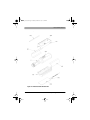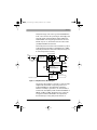
1
Agilent Technologies
Errata
Agilent E-Series E9320 Peak and Average Power Sensors
Operating and Service Guide
Information provided in this supplement is to update the Operating and Service Guide for
E-Series E9320 Peak and Average Power Sensors.
Updates
Accessories Shipped with the Instrument
The following items are shipped with every purchase of E-Series E9320 power sensors:
•
Certificate of Calibration
•
E-Series E9320 Product Reference CD
Verify that any options ordered are included with the shipment by checking the packing list
included with the shipment.
©Agilent Technologies, Inc. 2003–2012
December 14, 2012
e9321_90001.book Page 1 Tuesday, March 18, 2003 10:44 AM
E-Series E9320 Peak
and Average Power
Sensors
Operating and
Service Guide
e9321_90001.book Page 2 Tuesday, March 18, 2003 10:44 AM
General
Information contained in this document is subject to
change without notice. Agilent Technologies makes
no warranty of any kind with regard to this material,
including, but not limited to, the implied warranties of
merchantability and fitness for a particular purpose.
Agilent Technologies shall not be liable for errors
contained herein or for incidental or consequential
damages in connection with the furnishings,
performance, or use of this material. No part of this
document may be photocopied, reproduced, or
translated to another language without the prior
written consent of Agilent Technologies.
Copyright 2003–2012 Agilent Technologies
Agilent Technologies, Inc.
5301 Stevens Creek Blvd. Santa Clara, CA 95052 USA
Manual Part No. E9321-90001
Printed in Malaysia
December 14, 2012
Legal Information
Certification
Agilent Technologies certifies that this product met its
published specifications at the time of shipment from
the factory. Agilent Technologies further certifies that
its calibration measurements are traceable to the
United States National Institute of Standards and
Technology, to the extent allowed by the Institute’s
calibration facility, and to the calibration facilities of
other International Standards Organization members.
2
E-Series E9320 Operating and Service Guide
e9321_90001.book Page 3 Tuesday, March 18, 2003 10:44 AM
Safety Symbols
Safety Symbols
The following symbols on the instrument and in the
documentation indicate precautions which must be taken to
maintain safe operation of the instrument.
The Instruction Documentation Symbol. The product
is marked with this symbol when it is necessary for
the user to refer to the instructions in the supplied
documentation.
Safety
Notices
This guide uses warnings and cautions to denote hazards
WARNING
A warning calls attention to a procedure, practice or the like,
which, if not correctly performed or adhered to, could result in
injury or loss of life. Do not proceed beyond a warning until the
indicated conditions are fully understood and met.
CA UT I ON
A caution calls attention to a procedure, practice or the like
which, if not correctly performed or adhered to, could result in
damage to or the destruction of part or all of the equipment.
Do not proceed beyond a caution until the indicated
conditions are fully understood and met.
E-Series E9320 Operating and Service Guide
3
e9321_90001.book Page 4 Tuesday, March 18, 2003 10:44 AM
General Safety Information
General Safety Information
The following general safety precautions must be observed
during all phases of operation, service, and repair of this
instrument. Failure to comply with these precautions or with
specific warnings elsewhere in this manual violates safety
standards of design, manufacture, and intended use of the
instrument. Agilent Technologies assumes no liability for the
customer’s failure to comply with these requirements.
WARNING
BEFORE CONNECTING THE POWER SENSOR TO OTHER
INSTRUMENTS ensure that all instruments are connected to
the protective (earth) ground. Any interruption of the
protective earth grounding will cause a potential shock
hazard that could result in personal injury.
Sound Emission
Herstellerbescheinigung
Diese Information steht im Zusammenhang mit den
Anforderungen der Maschinenlarminformationsverordnung
vom 18 Januar 1991.
• Sound Pressure LpA < 70 dB.
• Am Arbeitsplatz.
• Normaler Betrieb.
• Nach DIN 45635 T. 19 (Typprufung).
4
E-Series E9320 Operating and Service Guide
e9321_90001.book Page 5 Tuesday, March 18, 2003 10:44 AM
General Safety Information
Manufacturers Declaration
This statement is provided to comply with the requirements of
the German Sound DIN 45635 T. 19 (Typprufung).
• Sound Pressure LpA < 70 dB.
• At operator position.
• Normal operation.
• According to ISO 7779 (Type Test).
E-Series E9320 Operating and Service Guide
5
e9321_90001.book Page 6 Tuesday, March 18, 2003 10:44 AM
General Safety Information
6
E-Series E9320 Operating and Service Guide
e9321_90001.book Page 7 Tuesday, March 18, 2003 10:44 AM
Contents
Contents
Safety Symbols........................................................................ 3
General Safety Information ..................................................... 4
Sound Emission.................................................................... 4
Contents .................................................................................. 7
Introduction...............................................................................9
General Information .............................................................. 10
Initial Inspection................................................................. 10
Power Meter and Sensor Cable Requirements.................... 11
Interconnections ................................................................ 11
Calibration.......................................................................... 11
The E-Series E9320 Power Sensors in Detail ........................ 13
Specifications and
Characteristics ......................................................................15
Introduction........................................................................... 16
Specifications ....................................................................... 17
Service .......................................................................................43
General Information .............................................................. 44
Cleaning ............................................................................. 44
Performance Test................................................................ 45
Replaceable Parts............................................................... 47
Service .................................................................................. 51
Principles of Operation ....................................................... 51
Troubleshooting.................................................................. 54
Repair of Defective Sensor ................................................. 54
Disassembly Procedure ...................................................... 55
Reassembly Procedure ....................................................... 55
Addendum.............................................................................57
E-Series E9320 Operating and Service Guide
7
e9321_90001.book Page 8 Tuesday, March 18, 2003 10:44 AM
Contents
8
E-Series E9320 Operating and Service Guide
e9321_90001.book Page 9 Tuesday, March 18, 2003 10:44 AM
1
What You’ll Find
In This Chapter
Introduction
This Chapter introduces you to the E-series E9320 power
sensors. It contains the following sections:
•
•
General Information on page 10
Initial Inspection on page 10
•
Power Meter and Sensor Cable Requirements on
page 11
•
•
Interconnections on page 11
The E-Series E9320 Power Sensors in Detail on page
13
e9321_90001.book Page 10 Tuesday, March 18, 2003 10:44 AM
General Information
General Information
Welcome to the E-series E9320 power sensors Operating and
Service Guide! This guide contains information about the
initial inspection, connection, and specifications of the Eseries E9320 power sensors. You can also find a copy of this
guide on the CD-ROM supplied with the EPM-P series peak
and average power meters.
To make best use of your sensor refer to the chapter “Using
E-Series E9320 Sensors” in the EPM-P Series Power Meters
Operating and Service Guide.
Initial Inspection
Inspect the shipping container for damage. If the shipping
container or packaging material is damaged, it should be kept
until the contents of the shipment have been checked
mechanically and electrically. If there is mechanical damage,
notify the nearest Agilent office. Keep the damaged shipping
materials (if any) for inspection by the carrier and an Agilent
representative. If required, you can find a list of Agilent Sales
and Service offices on page 56.
10
E-Series E9320 Operating and Service Guide
e9321_90001.book Page 11 Tuesday, March 18, 2003 10:44 AM
General Information
Power Meter and Sensor Cable
Requirements
The E-series E9320 power sensors are compatible ONLY with
the EPM-P series power meters and with E9288 sensor
cables. (The E9288 cables are color coded to help distinguish
them from the 11730 series cables.)
Interconnections
Connect one end of an E9288 sensor cable to the E-series
E9320 power sensor and connect the other end of the cable to
the power meter’s channel input. Allow a few seconds for the
power meter to download the data contained in the power
sensor.
Ensure power sensors and cables are attached and removed
in an indoor environment.
Calibration
To carry out a zero and calibration cycle as requested by the
power meter proceed as follows:
•
Ensure the E-series E9320 power sensor is disconnected
from any signal source. On the power meter, press
Zero
, Zero (or Zero A / Zero B ). During zeroing
Cal
the wait symbol is displayed.
When the wait period is complete connect the E-series E9320
power sensor to the power meter’s POWER REF output.
•
T IP
Press Cal (or Cal , Cal A / Cal B ). The wait symbol is
again displayed during calibration.
You can reduce the steps required to carry out the zero and
calibration procedure as follows:
E-Series E9320 Operating and Service Guide
11
e9321_90001.book Page 12 Tuesday, March 18, 2003 10:44 AM
General Information
Connect the power sensor to the POWER REF output.
•
Press Zero
and Zero + Cal . (For dual channel
Cal
meters, press Zero + Cal , Zero + Cal A or
Zero + Cal B as required.)
On completion, the power meter and sensor are ready to
connect to the device under test (DUT).
WARNING
CAUTION
BEFORE CONNECTING THE POWER SENSOR TO OTHER
INSTRUMENTS ensure that all instruments are connected to
the protective (earth) ground. Any interruption of the
protective earth grounding will cause a potential shock hazard
that could result in personal injury.
The measurement connector (for connection to DUT) is
Type-N (male). A torque wrench should be used to tighten
these connectors. Use a 3/4-inch open-end wrench and
torque to 12 in-lb (135 Ncm) for the Type-N connector.
Recommended Calibration Interval
Agilent Technologies recommends a one-year calibration cycle
for the E-series E9320 peak and average power sensors.
12
E-Series E9320 Operating and Service Guide
e9321_90001.book Page 13 Tuesday, March 18, 2003 10:44 AM
The E-Series E9320 Power Sensors in Detail
The E-Series E9320 Power
Sensors in Detail
The E-series E9320 power sensors have two frequency
ranges. The E9325A, E9326A, and E9327A have a frequency
range of 50 MHz to 18 GHz while the 50 MHz to 6 GHz range of
the E9321A, E9322A, and E9323A covers most wireless
communication applications.
The sensors have two independent measurement paths as
shown in Figure 1.
Average Only Path
RF IN
50ohm
Load Filter*
(300 kHz, 1.5 MHz
5 MHz low pass)
Switched
Gain
Preamp
Chopper
CW Differential
AMP
Sensor Diode
Bulkhead
Average
Only Path
CHOP/CLOCK
CHOP/GAIN
Normal
Path
Selectable Gain
Differential Amplifier*
(300 kHz, 1.5 MHz, 5 MHz)
PEAK AUTO-ZERO
* Bandwidth is sensor dependent
Thermistor Bias
I2 C Buffer
Gain/Mode Control
Sensor ID
E2 PROM
Normal
Path
GAIN SELECT
SERIAL BUS
Figure 1 Simplified Sensor Block Diagram
Use the default normal path for continuously sampled
measurements of modulated signals and time gated
measurements. For each frequency range there is a choice of
sensors with three video (modulation) bandwidths.
E-Series E9320 Operating and Service Guide
13
e9321_90001.book Page 14 Tuesday, March 18, 2003 10:44 AM
The E-Series E9320 Power Sensors in Detail
•
E9321A and E9325A sensors with 300 kHz bandwidth are
suitable for measuring TDMA signals such as GSM.
•
E9322A and E9326A sensors with 1.5 MHz bandwidth are
suitable for measuring IS-95 CDMA signals.
E9323A and E9327A sensors with 5 MHz bandwidth are
suitable for measuring W-CDMA signals.
•
Note however, that the sensors with widest bandwidth have
the smallest dynamic range (in normal mode). If dynamic
range is an important factor, use the sensor model with just
enough video bandwidth for the measurement you want to
make.
The average-only path is suitable for average power
measurements of Continuous Wave (CW) and constant
amplitude signals between -65 dBm (sensor dependent) and
+20 dBm. The average-only path can also be used to measure
true average power of any complex modulated signal below 20 dBm.
Calibration factors, linearity, temperature, and bandwidth
compensation data are stored in the sensor EEPROM during
the manufacturing process. All the compensation data is
downloaded to the EPM-P series power meter at power-on or
when the sensor is connected. You only need to enter the
frequency of the RF signal you are measuring to achieve a high
degree of accuracy.
14
E-Series E9320 Operating and Service Guide
e9321_90001.book Page 15 Tuesday, March 18, 2003 10:44 AM
2
What You’ll Find
In This Chapter
Specifications and
Characteristics
This Chapter describes the specifications and
characteristics of the E-series E9320 power sensors. It
contains the following sections:
•
“Introduction” on page 16
•
“Specifications” on page 17
e9321_90001.book Page 16 Tuesday, March 18, 2003 10:44 AM
Introduction
Introduction
E-series E9320 power sensors are designed for use with the
Agilent EPM series power meters. The E-series E9320 power
sensors have two measurement paths:
•
Normal path: (default mode) for peak, average and
time-related measurements.
•
Average-only path: is designed primarily for average
power measurements on low level signals.
These specifications are valid ONLY after zero and calibration
of the power meter and sensor.
Supplemental characteristics, which are shown in italics, are
intended to provide information useful in applying the power
sensors by giving typical, but nonwarranted performance
parameters. These characteristics are shown in italics or
denoted as “typical”, “nominal” or “approximate”.
16
E-Series E9320 Operating and Service Guide
e9321_90001.book Page 17 Tuesday, March 18, 2003 10:44 AM
Specifications
Specifications
Frequency, Bandwidth, and Power Range
Table 1 Frequency, Bandwidth, and Power Range
Power Range
Sensor
Maximum
Video
Bandwidth
Frequency
Range
Average
Normal
only Mode Mode*
E9321A
300 kHz
50 MHz
to
6 GHz
–65 dBm
to
+20 dBm
–50 dBm
to
+20 dBm
E9325A
300 kHz
50 MHz
to
18 GHz
–65 dBm
to
+20 dBm
–50 dBm
to
+20 dBm
E9322A
1.5 MHz
50 MHz
to
6 GHz
–60 dBm
to
+20 dBm
–45 dBm
to
+20 dBm
E9326A
1.5 MHz
50 MHz
to
18 GHz
–60 dBm
to
+20 dBm
–45 dBm
to
+20 dBm
E9323A
5 MHz
50 MHz
to
6 GHz
–60 dBm
to
+20 dBm
–40 dBm
to
+20 dBm
E9327A
5 MHz
50 MHz
to
18 GHz
–60 dBm
to
+20 dBm
–40 dBm
to
+20 dBm
* For average power measurements, Free Run acquisition mode.
E-Series E9320 Operating and Service Guide
17
e9321_90001.book Page 18 Tuesday, March 18, 2003 10:44 AM
Specifications
Maximum Power, RF Connector
Table 2 Maximum Power, RF Connector
Sensor
E9321A
E9322A
E9323A
E9325A
E9326A
E9327A
18
RF
Connector
N-Type (m)
Maximum
Maximum Peak
Average Power Power
+23 dBm average
+30 dBm,
<10µs duration
E-Series E9320 Operating and Service Guide
e9321_90001.book Page 19 Tuesday, March 18, 2003 10:44 AM
Specifications
Measurement Ranges
The E-series E9320 power sensors have two measurement
ranges (Lower and Upper) as shown in Table 3, Table 4, and
Table 5.
Table 3 Lower and Upper Measurement Ranges
E9321A and E9325A
Normal
mode
Average only
mode
Lower Range (Min. Power)
−50 dBm
−65 dBm
Lower Range (Max. Power)
Lower to Upper Auto Range
Point
+0.5 dBm
−17.5 dBm1
Upper to Lower Auto Range
Point
-9.5 dBm
-18.5 dBm
Upper Range (Min. Power)
−35 dBm
−50 dBm
Upper Range (Max. Power
+20 dBm
+20 dBm1
1
Applies to CW and constant amplitude signals only
above −20 dBm.
E-Series E9320 Operating and Service Guide
19
e9321_90001.book Page 20 Tuesday, March 18, 2003 10:44 AM
Specifications
Table 4 Lower and Upper Measurement Ranges
E9322A and E9326A
Normal
mode
Average only
mode
Lower Range (Min. Power)
−45 dBm
−60 dBm
Lower Range (Max. Power)
Lower to Upper Auto Range
Point
−5 dBm
−13.5 dBm1
Upper to Lower Auto Range
Point
−15 dBm
−14.5 dBm
Upper Range (Min. Power)
−35 dBm
−45 dBm
Upper Range (Max. Power
+20 dBm
+20 dBm1
1
Applies to CW and constant amplitude signals only
above −20 dBm.
20
E-Series E9320 Operating and Service Guide
e9321_90001.book Page 21 Tuesday, March 18, 2003 10:44 AM
Specifications
Table 5 Lower and Upper Measurement Ranges
E9323A and E9327A
Normal
mode
Average only
mode
Lower Range (Min. Power)
−40 dBm
−60 dBm
Lower Range (Max. Power)
Lower to Upper Auto Range
Point
−5 dBm
−10.5 dBm1
Upper to Lower Auto Range
Point
−15 dBm
−11.5 dBm
Upper Range (Min. Power)
−30 dBm
−35 dBm
Upper Range (Max. Power
+20 dBm
+20 dBm1
1
Applies to CW and constant amplitude signals only
above −20 dBm.
E-Series E9320 Operating and Service Guide
21
e9321_90001.book Page 22 Tuesday, March 18, 2003 10:44 AM
Specifications
Power Sensor Maximum SWR
Table 6 Power Sensor Maximum SWR
Maximum SWR ≤0 dBm
Sensor
E9321A
E9325A
50 MHz to 2 GHz:
2 GHz to 10 GHz:
10 GHz to 16 GHz:
16 GHz to 18 GHz:
1.12
1.16
1.23
1.28
E9322A
E9326A
50 MHz to 2 GHz:
2 GHz to 12 GHz:
12 GHz to 16 GHz:
16 GHz to 18 GHz:
1.12
1.18
1.21
1.27
E9323A
E9327A
50 MHz to 2 GHz:
2 GHz to 16 GHz:
16 GHz to 18 GHz:
1.14
1.22
1.26
1.300
SWR
1.250
-30
1.200
-20
-10
1.150
0
1.100
10
1.050
20
18GHz
17GHz
16GHz
15GHz
14GHz
9GHz
12GHz
6GHz
1GHz
0.5GHz
0.3GHz
0.05GHz
0.02GHz
1.000
Freq
Figure 2 Typicl SWR (50 MHz to 18 GHz) for the E9321A and E9325A
sensors at various power levels
22
E-Series E9320 Operating and Service Guide
e9321_90001.book Page 23 Tuesday, March 18, 2003 10:44 AM
Specifications
1.300
SWR
1.250
-30
1.200
-20
-10
1.150
0
1.100
10
20
1.050
18GHz
17GHz
16GHz
15GHz
14GHz
12GHz
9GHz
6GHz
1GHz
0.5GHz
0.3GHz
0.05GHz
0.02GHz
1.000
Freq
Figure 3 Typical SWR (50 MHz to 18 GHz) for the E9322A and E9326A
sensors at various power levels
1.300
SWR
1.250
-30
-20
1.200
-10
1.150
0
1.100
10
1.050
20
18GHz
17GHz
16GHz
15GHz
14GHz
12GHz
9GHz
6GHz
1GHz
0.5GHz
0.3GHz
0.05GHz
0.02GHz
1.000
Freq
Figure 4 Typical SWR (50 MHz to 18 GHz) for the E9323A and E9327A
sensors at various power levels
E-Series E9320 Operating and Service Guide
23
e9321_90001.book Page 24 Tuesday, March 18, 2003 10:44 AM
Specifications
Sensor Linearity
Table 7 Power Sensor Linearity Normal Mode
(upper and lower range)
Sensor
Temperature
(25 ±10°C)
Temperature
(0 to 55°C)
E9321A
E9325A
±4.2%
±5.0%
E9322A
E9326A
±4.2%
±5.0%
E9323A
E9327A
±4.2%
±5.5%
Table 8 Power Sensor Linearity Average-Only Mode
(upper and lower range)
Sensor
Temperature
(25 ±10°C)
Temperature
(0 to 55°C)
E9321A
E9325A
±3.7%
±4.5%
E9322A
E9326A
±3.7%
±4.5%
E9323A
E9327A
±3.7%
±5.0%
If the temperature changes after calibration and the meter and
sensor are NOT recalibrated, the following additional linearity
errors should be added to the Power Linearity figures in Table
7 and Table 8.
24
E-Series E9320 Operating and Service Guide
e9321_90001.book Page 25 Tuesday, March 18, 2003 10:44 AM
Specifications
Table 9 Additional Linearity Error (normal and averageonly modes)
Temperature
(25 ±10°C)
Sensor
Temperature
(0 to 55°C)
E9321A
E9325A
±1.0%
±1.0%
E9322A
E9326A
±1.0%
±1.5%
E9323A
E9327A
±1.0%
±2.0%
2.00
%
1.50
1.00
0.50
Average Only
0.00
Normal (lower range)
Normal (upper range)
-0.50
-1.00
-1.50
20
18
6
10
14
2
0
-3
-7
-1
5
-1
1
-2
3
-1
9
-3
0
-2
7
-2.00
dBm
Figure 5 Typical Power Linearity at 25°C for E9323A and E9327A
5 MHz bandwidth sensors after zero and calibration, with
associated measurement uncertainty
E-Series E9320 Operating and Service Guide
25
e9321_90001.book Page 26 Tuesday, March 18, 2003 10:44 AM
Specifications
Power Range
Measurement Uncertainty
−30 to −20 dBm
±0.9%
−20 to −10 dBm
±0.8%
−10 to 0 dBm
±0.65%
0 to +10 dBm
±0.55%
+10 to +20 dBm
±0.45%
+20 dBm
±4.0%
±2.0%
±2.0%
±4.0%
0 dBm
−60 dBm
−65 dBm
−65 dBm−60 dBm
0 dBm
+20 dBm
Figure 6 Relative Mode Power Measurement Linearity with an
EPM-P series power meter, at 25°C (typical)
26
E-Series E9320 Operating and Service Guide
e9321_90001.book Page 27 Tuesday, March 18, 2003 10:44 AM
Specifications
Figure 6 shows the typical uncertainty in making a relative
power measurement, using the same power meter channel
and the same power sensor to obtain the reference and
measured values. It also assumes that negligible change in
frequency and mismatch error occurs when transitioning from
the power level used as the reference to the power level
measured.
E-Series E9320 Operating and Service Guide
27
e9321_90001.book Page 28 Tuesday, March 18, 2003 10:44 AM
Specifications
Peak Flatness
The peak flatness is the flatness of a Peak-to-Average ratio
measurement for various tone separations for an equal
magnitude two-tone RF input. Figure 7, Figure 8, and Figure 9
refer to the relative error in Peak-to-Average measurement as
the tone separation is varied. The measurements were
performed at −10 dBm average power using an E9288A sensor
cable.
Error (dB)
0.5
0.0
-0.5
-1.0
-1.5
-2.0
HIGH
LOW
MED
OFF
-2.5
-3.0
-3.5
0.0
1.0
2.0
3.0
4.0
5.0
6.0
Input Tone Seperation Frequency (MHz)
Figure 7 E9321A and E9325A Error in Peak-to-Average
Measurements for a Two-tone Input
(High, Medium, Low, and Off Filters)
28
E-Series E9320 Operating and Service Guide
e9321_90001.book Page 29 Tuesday, March 18, 2003 10:44 AM
Specifications
Error (dB)
0.5
0
-0.5
-1
-1.5
-2
HIGH
LOW
MED
OFF
-2.5
-3
-3.5
0.0
1.0
2.0
3.0
4.0
5.0
6.0
Input Tone Seperation Frequency (MHz)
Figure 8 Filter responses for the E9322A and E9326A power sensors
(High, Medium, Low, and Off)
Error (dB)
0.5
0.0
-0.5
-1.0
-1.5
-2.0
LOW
-2.5
MED
-3.0
OFF
HIGH
-3.5
0.0
1.0
2.0
3.0
4.0
5.0
6.0
Input Tone Seperation Frequency (MHz)
Figure 9 Filter responses for the E9323A and E9327A power sensors
(High, Medium, Low, and Off)
E-Series E9320 Operating and Service Guide
29
e9321_90001.book Page 30 Tuesday, March 18, 2003 10:44 AM
Specifications
Calibration Factor (CF) and Reflection
Coefficient (Rho)
Calibration Factor and Reflection Coefficient data are provided
at frequency intervals on a data sheet included with the power
sensor. This data is unique to each sensor. If you have more
than one sensor, match the serial number on the data sheet
with the serial number of the sensor you are using. The CF
corrects for the frequency response of the sensor. The EPM-P
Series power meter automatically reads the CF data stored in
the sensor and uses it to make corrections.
For power levels greater than 0 dBm, add to the calibration
factor uncertainty specification:
±0.1% per dB for E9321A and E9325A power sensors
±0.15% per dB for E9322A and E9326A power sensors
±0.2% per dB for E9323A and E9327A power sensors
Reflection coefficient (Rho) relates to the SWR according to
the formula:
SWR=(1+Rho)/(1−Rho)
Typical CF data are listed in Table 10.
The uncertainty analysis for the calibration of the sensors was
calculated in accordance with the ISO Guide. The uncertainty
data, reported on the calibration certificate, is the expanded
uncertainty with a 95% confidence level and a coverage factor
of 2.
30
E-Series E9320 Operating and Service Guide
e9321_90001.book Page 31 Tuesday, March 18, 2003 10:44 AM
Specifications
Table 10 Cal Factor Uncertainty at 0.1 mW (-10dBm)
Uncertainty (%)
(25 ±10°C)
Uncertainty(%)
(0 to 55°C)
50 MHz
Reference
Reference
100 MHz
±1.8
±2.0
300 MHz
±1.8
±2.0
500 MHz
±1.8
±2.0
800 MHz
±1.8
±2.0
1.0 GHz
±2.1
±2.3
1.2 GHz
±2.1
±2.3
1.5 GHz
±2.1
±2.3
2.0 GHz
±2.1
±2.3
3.0 GHz
±2.1
±2.3
4.0 GHz
±2.1
±2.3
5.0 GHz
±2.1
±2.3
6.0 GHz
±2.1
±2.3
7.0 GHz
±2.3
±2.5
8.0 GHz
±2.3
±2.5
9.0 GHz
±2.3
±2.5
11.0 GHz
±2.3
±2.5
12.0 GHz
±2.3
±2.5
13.0 GHz
±2.3
±2.5
14.0 GHz
±2.5
±2.8
15.0 GHz
±2.5
±2.8
16.0 GHz
±2.5
±2.8
17.0 GHz
±2.5
±2.8
18.0 GHz
±2.5
±2.8
Frequency
E-Series E9320 Operating and Service Guide
31
e9321_90001.book Page 32 Tuesday, March 18, 2003 10:44 AM
Specifications
Zero Set
This specification applies to a ZERO performed when the
sensor input is not connected to the POWER REFERENCE.
Table 11 Zero Set
Sensor
32
Zero Set
(Normal mode)
Zero Set
(Average-only Mode)
E9321A
E9325A
5 nW
0.17 nW
E9322A
E9326A
19 nW
0.5 nW
E9323A
E9327A
60 nW
0.6 nW
E-Series E9320 Operating and Service Guide
e9321_90001.book Page 33 Tuesday, March 18, 2003 10:44 AM
Specifications
Zero Drift and Measurement Noise
Table 12 Zero Drift and Measurement Noise
Zero Drift1
Measurement Noise 2
Sensor
Normal
Mode
Average only
Mode
Normal
Mode3
Normal
Mode 4
Average
only
Mode
E9321A
E9325A
<±5 nW
<±60 pW
<6 nW
<75 nW
<165 pW
E9322A
E9326A
<±5 nW
<±100 pW
<12 nW
<180 nW
<330 pW
E9323A
E9327A
<±40 nW
<±100 pW
<25 nW
<550 nW
<400 pW
1 Within 1 hour after zero set, at
a constant temperature, after a
24 hour warm-up of the power meter.
2 Measured
over a one minute interval, at a constant temperature,
two standard deviations, with averaging set to 1 (normal mode), 16
(for average-only mode, normal speed) and 32 (average-only mode,
x2 speed).
3 In
4
Free run acquisition mode.
Noise per sample, Video bandwidth set to OFF with no averaging
(i.e., averaging set to 1) - see “Effect of Video Bandwidth Settings”
and Table 14.
E-Series E9320 Operating and Service Guide
33
e9321_90001.book Page 34 Tuesday, March 18, 2003 10:44 AM
Specifications
Effect of Averaging on Noise: Averaging over 1 to 1024
readings is available for reducing noise. Table 12 provides the
Measurement Noise for a particular sensor. Use the Noise
Multipliers in Table 13 for the appropriate speed (normal or
x2), or measurement mode (normal and average-only), and the
number of averages to determine the total Measurement
Noise value.
In addition, for x2 speed (in normal mode) the total
Measurement Noise should be multiplied by 1.2, and for fast
speed (in normal mode) the multiplier is 3.4. Note that in fast
speed no additional averaging is implemented.
34
E-Series E9320 Operating and Service Guide
e9321_90001.book Page 35 Tuesday, March 18, 2003 10:44 AM
Specifications
Table 13 Noise Multipliers
Noise Multiplier
Average-only
Number of
Averages
Normal
Normal
Speed
X2
Speed
Normal Speed,
Free run acquisition
1
5.5
6.5
1.0
2
3.89
4.6
0.94
4
2.75
3.25
0.88
8
1.94
2.3
0.82
16
1.0
1.63
0.76
32
0.85
1.0
0.70
64
0.61
0.72
0.64
128
0.49
0.57
0.58
256
0.34
0.41
0.52
512
0.24
0.29
0.46
1024
0.17
0.2
0.40
Example: E9321A power sensor, Number of Averages = 4,
Free Run acquisition, normal mode, x2 speed.
Measurement Noise calculation:
(<6 nW x 0.88 x 1.2) = <6.34 nW
E-Series E9320 Operating and Service Guide
35
e9321_90001.book Page 36 Tuesday, March 18, 2003 10:44 AM
Specifications
Effect of Video Bandwidth Setting: The noise per sample is
reduced by applying the meter video bandwidth reduction
filter setting (High, Medium, or Low). If averaging is
implemented, this will dominate any effect of changing the
video bandwidth.
Table 14 Effect of Video Bandwidth on Noise per Sample
Noise Multipliers
Sensor
Low
Medium
High
E9321A
E9325A
0.32
0.5
0.63
E9322A
E9326A
0.50
0.63
0.80
E9323A
E9327A
0.40
0.63
1.0
Example: E9322A power sensor, triggered acquisition, high
video bandwidth.
Noise per sample calculation:
(<180nW x 0.80) = <144 nW
Effect of Time-Gating on Measurement Noise: The
measurement noise will depend on the time gate length over
which measurements are made. Effectively 20 averages are
carried out every 1 µs of gate length.
36
E-Series E9320 Operating and Service Guide
e9321_90001.book Page 37 Tuesday, March 18, 2003 10:44 AM
Specifications
Settling Times
Average Only Mode:
In normal and x2 speed mode, manual filter, 10 dB decreasing
power step, refer to Table 15.
Table 15 Averages vs. Settling Time (Average-only mode)
Number of
Averages
1
Settling Time (s)
Normal Speed Mode
X 2 Speed Mode
0.08
0.07
2
0.13
0.09
4
0.24
0.15
8
0.45
0.24
16
1.1
0.45
32
1.9
1.1
64
3.5
1.9
128
6.7
3.5
256
14
6.7
512
27
14
1024
57
27
In Fast mode, within the range −50 to +20 dBm, for a 10 dB
decreasing power step, the settling time is:
E4416A:
10 ms
E4417A:
20 ms
When a power step crosses the power sensor’s auto-range
switch point, add 25 ms.
E-Series E9320 Operating and Service Guide
37
e9321_90001.book Page 38 Tuesday, March 18, 2003 10:44 AM
Specifications
Normal Mode:
In Normal, free run acquisition mode, within the range −20 to
+20 dBm, for a 10 dB decreasing power step, the settling time
is dominated by the measurement update rate and is listed in
Table 16 for various filter settings.
Table 16 Settling Time vs. Averages
Settling Time
Number of
Averages
38
Free Run Acquisition Mode
Normal Speed
X 2 Speed
1
0.1 sec
0.08 sec
2
0.15 sec
0.1 sec
4
0.25 sec
0.15 sec
8
0.45 sec
0.25 sec
16
0.9 sec
0.45 sec
32
1.7 sec
0.9 sec
64
3.3 sec
1.7 sec
128
6.5 sec
3.3 sec
256
13.0 sec
6.5 sec
512
25.8 sec
13.0 sec
1024
51.5 sec
25.8 sec
E-Series E9320 Operating and Service Guide
e9321_90001.book Page 39 Tuesday, March 18, 2003 10:44 AM
Specifications
In normal mode, measuring in continuous or single acquisition
mode, the performance of rise times, fall times and 99%
settled results are shown in Table 17. Rise and fall time
specifications are for a 0.0 dBm pulse, with the rise time and
fall time measured between 10% to 90% points and upper
range selected.
Table 17 Rise and Fall Times vs. Sensor Bandwidth1
Video Bandwidth Setting
Sensor
E9321A
E9325A
E9322A
E9326A
E9323A
E9327A
Parameter
Low
Medium
High Off
Rise time < µs
2.6
1.5
0.9
0.3
Fall time < µs
2.7
1.5
0.9
0.5
Settling time
(rising) < µs
5.1
5.1
4.5
0.6
Settling time
(falling) < µs
5.1
5.1
4.5
0.9
Rise time < µs
1.5
0.9
0.4
0.2
Fall time < µs
1.5
0.9
0.4
0.3
Settling time
(rising) < µs
5.3
4.5
3.5
0.5
Settling time
(falling) < µs
5.3
4.5
3.5
0.9
Rise time < µs
0.9
0.4
0.2
0.2
Fall time < µs
0.9
0.4
0.2
0.2
Settling time
(rising) < µs
4.5
3.5
1.5
0.4
Settling time
(falling) < µs
4.5
3.5
2
0.4
1Rise and fall time specifications are only
valid when used
with the E9288A sensor cable (1.5 metres).
E-Series E9320 Operating and Service Guide
39
e9321_90001.book Page 40 Tuesday, March 18, 2003 10:44 AM
Specifications
Overshoot in response to power steps with fast rise times, i.e.,
less than the sensor rise time is less than 10%.
When a power step crosses the power sensor’s auto-range
switch point, add 10 µs.
40
E-Series E9320 Operating and Service Guide
e9321_90001.book Page 41 Tuesday, March 18, 2003 10:44 AM
Specifications
Physical Specifications
Table 18 Physical Specifications
Physical Characteristics
Net Weight
0.2 kg (0.45 lb)
Shipping Weight
0.55 kg (1.2 lb)
Dimensions
Length: 150 mm (5.9 in)
Width: 38 mm (1.5 in)
Height: 30 mm (1.2 in)
E-Series E9320 Operating and Service Guide
41
e9321_90001.book Page 42 Tuesday, March 18, 2003 10:44 AM
Specifications
42
E-Series E9320 Operating and Service Guide
e9321_90001.book Page 43 Tuesday, March 18, 2003 10:44 AM
3
What You’ll Find
In This Chapter
Service
This Chapter introduces you to the E-series E9320 power
sensors. It contains the following sections:
•
General Information on page 44
•
•
Service on page 51
Sales and Service Offices on page 56
e9321_90001.book Page 44 Tuesday, March 18, 2003 10:44 AM
General Information
General Information
This chapter contains information about general maintenance,
performance tests, troubleshooting and repair of E-series
E9320 power sensors.
Cleaning
Use a clean, damp cloth to clean the body of the
E-series E9320 power sensor.
Connector Cleaning
The RF connector beads deteriorate when contacted by
hydrocarbon compounds such as acetone, trichloroethylene,
carbon tetrachloride, and benzene.
Clean the connector only at a static free workstation.
Electrostatic discharge to the center pin of the connector will
render the power sensor inoperative.
Keeping in mind its flammable nature; a solution of pure
isopropyl or ethyl alcohol can be used to clean the connector.
Clean the connector face using a cotton swab dipped in
isopropyl alcohol. If the swab is too big use a round wooden
toothpick wrapped in a lint free cotton cloth dipped in
isopropyl alcohol.
44
E-Series E9320 Operating and Service Guide
e9321_90001.book Page 45 Tuesday, March 18, 2003 10:44 AM
General Information
Performance Test
Standing Wave Ratio (SWR) and Reflection
Coefficient (Rho) Performance Test
This section does not establish preset SWR test procedures
since there are several test methods and different equipment
available for testing the SWR or reflection coefficient.
Therefore, the actual accuracy of the test equipment must be
accounted for when measuring against instrument
specifications to determine a pass or fail condition. The test
system used must not exceed the system Rho uncertainties
shown in Table 19 when testing the E9325A, E9326A, and
E9327A. Use Table 20 when testing the E9321A, E9322A, and
E9323A.
Table 19 Reflection Coefficient for the E9321A and E9325A
Frequency
System Rho
Uncertainty
Measured
value
Maximum
Rho
50 MHz to 2 GHz
±0.010
0.057
2 GHz to 10 GHz
±0.010
0.074
10 GHz to 16 GHz
±0.010
0.103
16 GHz to 18 GHz
±0.010
0.123
E-Series E9320 Operating and Service Guide
45
e9321_90001.book Page 46 Tuesday, March 18, 2003 10:44 AM
General Information
Table 20 Reflection Coefficient for the E9322A and E9326A
Frequency
System Rho
Uncertainty
Measured
value
Maximum
Rho
50 MHz to 2 GHz
±0.010
0.057
2 GHz to 10 GHz
±0.010
0.083
10 GHz to 16GHz
±0.010
0.095
16 GHz to 18GHz
±0.010
0.119
Table 21 Reflection Coefficient for the E9323A and E9327A
Frequency
46
System Rho
Uncertainty
Measured
value
Maximum
Rho
50 MHz to 2 GHz
±0.010
0.065
2 GHz to 16GHz
±0.010
0.099
16 GHz to 18GHz
±0.010
0.115
E-Series E9320 Operating and Service Guide
e9321_90001.book Page 47 Tuesday, March 18, 2003 10:44 AM
General Information
Replaceable Parts
Table 22 is a list of replaceable parts. Figure 10 is the
illustrated parts breakdown (IPB) that identifies all of the
replaceable parts. To order a part, quote the Agilent part
number, specify the quantity required, and address the order
to the nearest Agilent office.
N OT E
Within the USA, it is better to order directly from the Agilent
Parts Center in Roseville, California. Ask your nearest Agilent
office for information and forms for the “Direct Mail Order
System.” Also your nearest Agilent office can supply toll free
telephone numbers for ordering parts and supplies
E-Series E9320 Operating and Service Guide
47
e9321_90001.book Page 48 Tuesday, March 18, 2003 10:44 AM
General Information
.
Figure 10 Illustrated Parts Break down
48
E-Series E9320 Operating and Service Guide
e9321_90001.book Page 49 Tuesday, March 18, 2003 10:44 AM
General Information
Table 22 Replaceable Parts List
Reference
Designation
Part
Number
A1/A2
E9321A
E9321-60011
1
SENSOR MODULE
A1/A2
E9321A
E9321-69011
1
RESTORED SENSOR
MODULE
A1/A2
E9322A
E9322-60004
1
SENSOR MODULE
A1/A2
E9322A
E9322-69004
1
RESTORED SENSOR
MODULE
A1/A2
E9323A
E9323-60002
1
SENSOR MODULE
A1/A2
E9323A
E9323-69002
1
RESTORED SENSOR
MODULE
A1/A2
E9325A
E9325-60002
1
SENSOR MODULE
A1/A2
E9325A
E9325-69002
1
RESTORED SENSOR
MODULE
A1/A2
E9326A
E9326-60002
1
SENSOR MODULE
A1/A2
E9326A
E9326-69002
1
RESTORED SENSOR
MODULE
A1/A2
E9327A
E9327-60002
1
SENSOR MODULE
A1/A2
E9327A
E9327-69002
1
RESTORED SENSOR
MODULE
E-Series E9320 Operating and Service Guide
Qty
Description
49
e9321_90001.book Page 50 Tuesday, March 18, 2003 10:44 AM
General Information
Table 22 Replaceable Parts List
N OT E
50
Reference
Designation
Part
Number
MP1 and MP2
E9321-40001
2
SHELL-PLASTIC
MP3 and MP4
E9321-20002
2
CHASSIS
MP8 and MP9
E9321-00001
2
SHIELD
MP26
E9321-80001
1
LABEL, ID E9321A
MP26
E9322-80001
1
LABEL, ID E9322A
MP26
E9323-80001
1
LABEL, ID E9323A
MP26
E9325-80001
1
LABEL, ID E9325A
MP26
E9326-80001
1
LABEL, ID E9326A
MP26
E9327-80001
1
LABEL, ID E9327A
MP27
E9321-80002
2
LABEL, POWER
SENSOR
MP30
E9321-80003
1
LABEL, CAL/ESD
Qty
Description
The A1/A2 parts are applicable only for Agilent Service Center
as calibration is required.
E-Series E9320 Operating and Service Guide
e9321_90001.book Page 51 Tuesday, March 18, 2003 10:44 AM
Service
Service
Service instructions consist of principles of operation,
troubleshooting, and repairs.
Principles of Operation
The Power Sensor ‘bulkhead’ assembly converts input RF to a
low frequency voltage signal representing the RF power
envelope. The input is AC coupled to a 3dB attenuator
followed by a 50 ohm load resistor. Two diodes are connected
to the load resistor, forming a pair of half-wave detectors with
opposite polarity and complementary voltage output. The
detected signal passes through a low-pass load filter. The
cutoff frequency of the filter is 300 kHz, 1.5 MHz, or 5 MHz,
depending on the model/ bandwidth specification of the
sensor.
The detected signal can now follow one of two paths. The
average-only signal path is optimized for high sensitivity and
low drift at the expense of detector video bandwidth. This path
chops the signal to a carrier frequency around 440Hz to
remove sensitivity to DC offsets, then amplifies the AC signal.
Amplification and chopping parameters are much the same as
in previous Agilent diode sensors, with typical dynamic power
range of -65 to +20 dBm.
The chopper is a switch that connects the two balanced
signals to the two inputs of a differential amplifier. Thus, the
small DC signal from the detector is converted to an AC signal.
The output of the differential amplifier is connected to a
switched gain preamplifier.
E-Series E9320 Operating and Service Guide
51
e9321_90001.book Page 52 Tuesday, March 18, 2003 10:44 AM
Service
The dynamic range of the sensor is greater than 80dB in this
mode, so the sensor has two power ranges. On the high power
range the signal is attenuated before further amplification.
The bandwidth of the chopped signal is limited to less than
half the chop rate. So, this method cannot be used for wide
(~5 MHz) bandwidth measurements.
The normal path is used to detect the instantaneous power of
an RF signal and is optimized for a bandwidth of up to 5MHz.
The peak path trade off includes reduced dynamic range and
increased temperature sensitivity.
Average Only Path
RF IN
50ohm
Load Filter*
(300 kHz, 1.5 MHz
5 MHz low pass)
Switched
Gain
Preamp
Chopper
CW Differential
AMP
Sensor Diode
Bulkhead
Average
Only Path
CHOP/CLOCK
CHOP/GAIN
Normal
Path
Selectable Gain
Differential Amplifier*
(300 kHz, 1.5 MHz, 5 MHz)
PEAK AUTO-ZERO
* Bandwidth is sensor dependent
Thermistor Bias
I2 C Buffer
Gain/Mode Control
Sensor ID
E2 PROM
Normal
Path
GAIN SELECT
SERIAL BUS
Figure 11 Simplified Sensor Block Diagram
The output of the load filter is connected to a gain selectable
amplifier with a bandwidth corresponding to the sensor
model/ bandwidth spec. The differential configuration
minimizes sensitivity to ground noise, dc offset and drift. In
normal mode, the amplifier provides maximum bandwidths of
300 kHz, 1.5 MHz or 5 MHz, allowing the user to match the
test signal’s modulation bandwidth to the sophisticated
instrument data processing. This permits the meter to
52
E-Series E9320 Operating and Service Guide
e9321_90001.book Page 53 Tuesday, March 18, 2003 10:44 AM
Service
measure burst average and peak power, to compute
peak-to-average ratios, and display other time-gated power
profiles on the power meter's large LCD screen.
The three dimensional Calibration data is stored in an
EEPROM on the sensor PCA. This data is unique to each
sensor and consists of frequency vs. input power vs.
temperature. Upon power-up, or when the sensor cable is
connected, these calibration factors are downloaded into the
EPM-P (E4416A/17A) series power meters. This means that
the operator is not required to enter any calibration
information when changing sensors, simply entering the
frequency of the input signal is all that is required
E-Series E9320 Operating and Service Guide
53
e9321_90001.book Page 54 Tuesday, March 18, 2003 10:44 AM
Service
Troubleshooting
Troubleshooting information is intended to first isolate the
power sensor, cable, or power meter as the defective
component. When the power sensor is isolated, an
appropriate Sensor Module must be used for repair. See
Table 22 on page 49.
If error message 241 or 310 is displayed on the power meter,
suspect a power sensor failure. Error 241 will occur if the
sensor is missing. An E9288 cable must be used to connect an
E-series 9320A sensor to an EPM-P Series power meter.
If no error message is displayed, but a problem occurs when
making a measurement, try replacing the cable from the
power meter to the power sensor. If the problem still exists, try
using a different power sensor to determine if the problem is
in the power meter or in the power sensor.
Electrostatic discharge will render the power sensor
inoperative. Do not, under any circumstances, open the power
sensor unless you and the power sensor are in a static free
environment.
Repair of Defective Sensor
There are no serviceable parts inside the E-series E9320
power sensors. If the sensor is defective, replace the entire
“module” with the appropriate “Restored Sensor Module”
listed in Table 22 on page 49.
54
E-Series E9320 Operating and Service Guide
e9321_90001.book Page 55 Tuesday, March 18, 2003 10:44 AM
Service
Disassembly Procedure
Disassemble the power sensor by performing the following
steps:
Disassemble the power sensor only in a static free
workstation. Electrostatic discharge renders the power sensor
inoperative.
Figure 12 Removing Power Sensor Shell
At the rear of the power sensor, insert the blade of a
screwdriver between the plastic shells (See Figure 12). To
prevent damage to the plastic shells use a screwdriver blade
as wide as the slot between the two shells.
Pry alternately at both sides of the connector J1 until the
plastic shells are apart. Remove the shells and the magnetic
shields.
Reassembly Procedure
Replace the magnetic shields and the plastic shells. Snap the
plastic shells together.
E-Series E9320 Operating and Service Guide
55
e9321_90001.book Page 56 Tuesday, March 18, 2003 10:44 AM
Service
Sales and Service Offices
In any correspondence or telephone conversations, refer to
the power sensor by its model number and full serial number.
With this information, the Agilent representative can quickly
determine whether your unit is still within its warranty period.
UNITED STATES
(tel) 800 829 4444
(fax) 800 829 4433
CANADA
(tel) 877 894 4414
(fax) 800 746 4866
CHINA
(tel) 800 810 0189
(fax) 800 820 2816
EUROPE
(tel) 31 20 547 2111
JAPAN
(tel) (81) 426 56 7832
(fax) (81) 426 56 7840
KOREA
(tel) (080) 769 0800
(fax) (080) 769 0900
LATIN AMERICA
(tel) (305) 269 7500
TAIWAN
(tel) 0800 047 866
(fax) 0800 286 331
OTHER ASIA PACIFIC
COUNTRIES
56
(tel) (65) 6375 8100
(fax) (65) 6755 0042
E-Series E9320 Operating and Service Guide