1
NO.
24ME-431
ISSUED: APR. 28, 1997
REVISED: FEB. 15, 2011
HOSHIZAKI
MODULAR ICE MAKER
MODEL
DSM-12CE
SERVICE MANUAL
CONTENTS
PAGE
I. SPECIFICATIONS--------------------------------------------------------------------------------------1
1. DIMENSIONS/CONNECTIONS-----------------------------------------------------------------1
[a] DSM-12CE [Auxiliary code V-1 and earlier]----------------------------------------------1
[b] DSM-12CE [Auxiliary code V-2 and later]-------------------------------------------------2
2. SPECIFICATIONS-----------------------------------------------------------------------------------3
[a] DSM-12CE (CONT.) [Auxiliary code V-1 and earlier]----------------------------------3
[b] DSM-12CE (UK) [Auxiliary code V-1 and earlier]---------------------------------------4
[c] DSM-12CE (CONT.) [Auxiliary code V-2 and later]-------------------------------------5
[d] DSM-12CE (UK) [Auxiliary code V-2 and later]------------------------------------------6
II. GENERAL INFORMATION--------------------------------------------------------------------------7
1. CONSTRUCTION-----------------------------------------------------------------------------------7
[a] LEFT SIDE VIEW WITH PANELS REMOVED------------------------------------------7
[b] CONTROL BOX---------------------------------------------------------------------------------9
[c] MECHANISM ASSEMBLY------------------------------------------------------------------ 11
III. INSTALLATION INSTRUCTIONS--------------------------------------------------------------- 13
1. UNPACKING---------------------------------------------------------------------------------------- 13
2. LOCATION------------------------------------------------------------------------------------------ 14
3. INSTALLATION------------------------------------------------------------------------------------ 15
4. ELECTRICAL CONNECTIONS---------------------------------------------------------------- 15
5. WATER SUPPLY AND DRAIN CONNECTIONS------------------------------------------ 17
IV. OPERATING INSTRUCTIONS------------------------------------------------------------------ 18
1. START UP------------------------------------------------------------------------------------------- 18
2. PREPARING THE ICEMAKER FOR LONG STORAGE--------------------------------- 19
V. MAINTENANCE-------------------------------------------------------------------------------------- 19
VI. TECHNICAL INFORMATION--------------------------------------------------------------------- 22
1. WATER CIRCUIT AND REFRIGERANT CIRCUIT---------------------------------------- 22
2. WIRING DIAGRAM------------------------------------------------------------------------------- 23
[a] Auxiliary code V-1 and earlier-------------------------------------------------------------- 23
[b] Auxiliary code V-2 and later----------------------------------------------------------------- 24
3. TIMING CHART------------------------------------------------------------------------------------ 25
[a] Auxiliary code V-1 and earlier-------------------------------------------------------------- 25
[b] Auxiliary code V-2 and later----------------------------------------------------------------- 26
4. SEQUENCE---------------------------------------------------------------------------------------- 27
5. PERFORMANCE DATA-------------------------------------------------------------------------- 29
6. ICE DISPENSING CAPACITY----------------------------------------------------------------- 30
VII. SERVICE DIAGNOSIS---------------------------------------------------------------------------- 32
1. Auxiliary code V-1 and earlier------------------------------------------------------------------ 32
2. Auxiliary code V-2 and later--------------------------------------------------------------------- 36
i
VIII. REMOVAL AND REPLACEMENT OF COMPONENTS--------------------------------- 40
1. PANELS---------------------------------------------------------------------------------------------- 40
[a] FRONT PANEL-------------------------------------------------------------------------------- 40
[b] UNDER COVER------------------------------------------------------------------------------- 40
[c] CABINET---------------------------------------------------------------------------------------- 40
[d] SIDE PANELS--------------------------------------------------------------------------------- 40
2. STORAGE BIN------------------------------------------------------------------------------------- 41
3. SERVICE FOR REFRIGERANT LINES----------------------------------------------------- 42
[a] SERVICE INFORMATION------------------------------------------------------------------ 42
[b] REFRIGERANT RECOVERY-------------------------------------------------------------- 43
[c] EVACUATING AND RECHARGE--------------------------------------------------------- 44
4. BRAZING-------------------------------------------------------------------------------------------- 45
5. DRIER------------------------------------------------------------------------------------------------ 46
6. COMPRESSOR------------------------------------------------------------------------------------ 47
7. HOT GAS VALVE---------------------------------------------------------------------------------- 48
8. EVAPORATOR------------------------------------------------------------------------------------- 49
9. FAN MOTOR---------------------------------------------------------------------------------------- 49
10. WATER VALVE------------------------------------------------------------------------------------ 50
11. GEAR MOTOR------------------------------------------------------------------------------------- 51
12. CONTROL BOX----------------------------------------------------------------------------------- 52
[a] Auxiliary code V-1 and earlier-------------------------------------------------------------- 52
[b] Auxiliary code V-2 and later----------------------------------------------------------------- 53
13. CONTROLLER BOARD [Auxiliary code V-2 and later]---------------------------------- 54
[a] CONTROLLER BOARD LAYOUT-------------------------------------------------------- 54
[b] CHECKING CONTROLLER BOARD---------------------------------------------------- 54
14. FUSE [Auxiliary code V-0 and earlier]-------------------------------------------------------- 55
15. MECHANISM ASSEMBLY---------------------------------------------------------------------- 56
[a] ARM---------------------------------------------------------------------------------------------- 56
[b] AGITATING MOTOR------------------------------------------------------------------------- 56
[c] TILTING MOTOR------------------------------------------------------------------------------ 57
[d] ICE MAKING SWITCH [Auxiliary code V-1 and earlier]----------------------------- 58
[e] ICE MAKING SWITCH [Auxiliary code V-2 and later]-------------------------------- 58
16. TRAY------------------------------------------------------------------------------------------------- 60
17. RELAY-4 (COMPRESSOR) [Auxiliary code V-1 and earlier]--------------------------- 61
18. THERMISTOR [Auxiliary code V-2 and later]---------------------------------------------- 62
[a] REMOVAL AND REPLACEMENT-------------------------------------------------------- 62
[b] DEFROST AND LOW WATER CONTROL--------------------------------------------- 63
[c] CHECKING THERMISTOR----------------------------------------------------------------- 63
19. TRANSFORMER---------------------------------------------------------------------------------- 64
20. POWER SUPPLY CORD------------------------------------------------------------------------ 64
IX. ADJUSTMENT OF ICE SIZE--------------------------------------------------------------------- 65
1. PROPER ICE SIZE------------------------------------------------------------------------------- 65
2. ADJUSTMENT------------------------------------------------------------------------------------- 66
[a] Auxiliary code V-1 and earlier-------------------------------------------------------------- 66
[b] Auxiliary code V-2 and later----------------------------------------------------------------- 67
ii
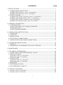
I. SPECIFICATIONS
1. DIMENSIONS/CONNECTIONS
[a] DSM-12CE [Auxiliary code V-1 and earlier]
1
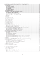
[b] DSM-12CE [Auxiliary code V-2 and later]
2
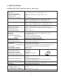
2. SPECIFICATIONS
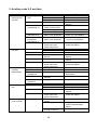
[a] DSM-12CE (CONT.) [Auxiliary code V-1 and earlier]
AC SUPPLY VOLTAGE
AMPERAGE
STARTING AMPERAGE
ELECTRIC CONSUMPTION
POWER FACTOR
POWER SUPPLY CAPACITY
ICE PRODUCTION PER 24 h
1PHASE 220-240 V 50 Hz
1.6 A (Ambient temp. 32°C, Water temp. 21°C)
7.5 A
260 W (Ambient temp. 32°C, Water temp. 21°C)
68 %
0.49 kVA (2.0 A)
Approx. 13 kg (Ambient temp. 10°C, Water temp. 10°C)
Approx. 10 kg (Ambient temp. 21°C, Water temp. 15°C)
Approx. 8 kg (Ambient temp. 32°C, Water temp. 21°C)
WATER CONSUMPTION PER 24 h Approx. 0.097 m3 (Ambient temp. 10°C, Water temp. 10°C)
Approx. 0.081 m3 (Ambient temp. 21°C, Water temp. 15°C)
Approx. 0.065 m3 (Ambient temp. 32°C, Water temp. 21°C)
SHAPE OF ICE
Shuttle
FREEZE CYCLE TIME
Approx. 12 min (Ambient temp. 21°C, Water temp. 15°C)
ICE PRODUCTION PER CYCLE
Approx. 0.085 kg / 27 pcs. (Ambient temp. 21°C, Water temp. 15°C)
STORAGE CAPACITY
Approx. 3 kg
ICE DISPENSING RATE
Approx. 700 g / min
DIMENSIONS
180 mm(W) x 510 mm(D) x 695 mm(H)
EXTERIOR
Acrylic Baked Steel (Cabinet), ABS Molding (Front Panel)
INSULATION
Polyurethane Foam
CONNECTION-ELECTRIC
Y-Type Con. (with CONT. Plug)
-WATER SUPPLY
Inlet G3/4 (Connected at rear side)
-DRAIN
Outlet R1/2 (Connected at rear side)
ICE MAKING SYSTEM
Mandrel type, Water agitated by plate
HARVESTING SYSTEM
Hot Gas Defrost, Water Pan tilted by motor
ICE DISPENSING SYSTEM
Auger driven by Push Switch
COMPRESSOR
Hermetic 125 W
Model TL4F
CONDENSER
Air-cooled, Fin and Tube type
HEAT REJECTION 300 W { 258 kcal/h } (Ambient temp. 32°C, Water temp. 21°C)
EVAPORATOR
Tin-plated copper tube on sheet with copper mandrel
REFRIGERANT CONTROL
Capillary Tube
REFRIGERANT CHARGE
R134a 65 g
ICE MAKING CONTROL
Ice thickness measurement
AVERAGE SIZE OF ICE (mm)
HARVESTING CONTROL
Thermostat
φ23
ICE STORAGE CONTROL
Microswitch
WATER SUPPLY CONTROL
Water Pan’s movement
14
ICE MAKING WATER CONTROL
Overflow
ELECTRICAL PROTECTION
Class I
5A Fuse
COMPRESSOR PROTECTION
Auto-reset Overload Protector
Thermostat on Evaporator (negative pressure protection)
GEAR MOTOR PROTECTION
Auto-reset Thermal Protector
WEIGHT
Net Weight 23 kg / Gross Weight 26 kg
PACKAGE
Carton 244 mm(W) x 584 mm(D) x 748 mm(H)
ACCESSORIES
Mounting Brace, Installation Kit
OPERATIONAL CONDITIONS
AMBIENT TEMP.
5 - 40°C
WATER SUPPLY TEMP.
5 - 35°C
WATER SUPPLY PRESSURE
0.05 - 0.78 MPa (0.5 - 8 bar)
We reserve the right to make changes in specifications and design without prior notice.
3
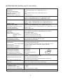
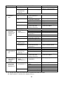
[b] DSM-12CE (UK) [Auxiliary code V-1 and earlier]
AC SUPPLY VOLTAGE
AMPERAGE
STARTING AMPERAGE
ELECTRIC CONSUMPTION
POWER FACTOR
POWER SUPPLY CAPACITY
ICE PRODUCTION PER 24 h
1PHASE 220-240 V 50 Hz
1.6 A (Ambient temp. 32°C, Water temp. 21°C)
7.5 A
260 W (Ambient temp. 32°C, Water temp. 21°C)
68 %
0.49 kVA (2.0 A)
Approx. 13 kg (Ambient temp. 10°C, Water temp. 10°C)
Approx. 10 kg (Ambient temp. 21°C, Water temp. 15°C)
Approx. 8 kg (Ambient temp. 32°C, Water temp. 21°C)
WATER CONSUMPTION PER 24 h Approx. 0.097 m3 (Ambient temp. 10°C, Water temp. 10°C)
Approx. 0.081 m3 (Ambient temp. 21°C, Water temp. 15°C)
Approx. 0.065 m3 (Ambient temp. 32°C, Water temp. 21°C)
SHAPE OF ICE
Shuttle
FREEZE CYCLE TIME
Approx. 12 min (Ambient temp. 21°C, Water temp. 15°C)
ICE PRODUCTION PER CYCLE
Approx. 0.085 kg / 27 pcs. (Ambient temp. 21°C, Water temp. 15°C)
STORAGE CAPACITY
Approx. 3 kg
ICE DISPENSING RATE
Approx. 700 g / min
DIMENSIONS
180 mm(W) x 510 mm(D) x 695 mm(H)
EXTERIOR
Acrylic Baked Steel (Cabinet), ABS Molding (Front Panel)
INSULATION
Polyurethane Foam
CONNECTION-ELECTRIC
Y-Type Con. (with UK Plug)
-WATER SUPPLY
Inlet G3/4 (Connected at rear side)
-DRAIN
Outlet R1/2 (Connected at rear side)
ICE MAKING SYSTEM
Mandrel type, Water agitated by plate
HARVESTING SYSTEM
Hot Gas Defrost, Water Pan tilted by motor
ICE DISPENSING SYSTEM
Auger driven by Push Switch
COMPRESSOR
Hermetic 125 W
Model TL4F
CONDENSER
Air-cooled, Fin and Tube type
HEAT REJECTION 300 W { 258 kcal/h } (Ambient temp. 32°C, Water temp. 21°C)
EVAPORATOR
Tin-plated copper tube on sheet with copper mandrel
REFRIGERANT CONTROL
Capillary Tube
REFRIGERANT CHARGE
R134a 65 g
ICE MAKING CONTROL
Ice thickness measurement
AVERAGE SIZE OF ICE (mm)
φ23
HARVESTING CONTROL
Thermostat
ICE STORAGE CONTROL
Microswitch
14
WATER SUPPLY CONTROL
Water Pan’s movement
ICE MAKING WATER CONTROL
Overflow
ELECTRICAL PROTECTION
Class I
5A Fuse 13A Fuse built in UK Plug
COMPRESSOR PROTECTION
Auto-reset Overload Protector
Thermostat on Evaporator (negative pressure protection)
GEAR MOTOR PROTECTION
Auto-reset Thermal Protector
WEIGHT
Net Weight 23 kg / Gross Weight 26 kg
PACKAGE
Carton 244 mm(W) x 584 mm(D) x 748 mm(H)
ACCESSORIES
Mounting Brace, Installation Kit
OPERATIONAL CONDITIONS
AMBIENT TEMP.
5 - 40°C
WATER SUPPLY TEMP.
5 - 35°C
WATER SUPPLY PRESSURE
0.05 - 0.78 MPa (0.5 - 8 bar)
We reserve the right to make changes in specifications and design without prior notice.
4
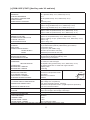
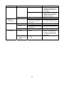
[c] DSM-12CE (CONT.) [Auxiliary code V-2 and later]
WATER CONSUMPTION PER 24h
SHAPE OF ICE
FREEZE CYCLE TIME
ICE PRODUCTION PER CYCLE
STORAGE CAPACITY
ICE DISPENSING RATE
DIMENSIONS
EXTERIOR
INSULATION
CONNECTIONS-ELECTRIC
-WATER SUPPLY
-DRAIN
ICE MAKING SYSTEM
HARVESTING SYSTEM
ICE DISPENSING SYSTEM
COMPRESSOR
CONDENSER
HEAT REJECTION
EVAPORATOR
REFRIGERANT CONTROL
REFRIGERANT CHARGE
ICE MAKING CONTROL
HARVESTING CONTROL
ICE STORAGE CONTROL
WATER SUPPLY CONTROL
ICE MAKING WATER CONTROL
ELECTRICAL PROTECTION
P.C. BOARD CIRCUIT PROTECTION
COMPRESSOR PROTECTION
1 PHASE 220-240V 50Hz
1.6 A (Ambient temp. 32 °C, Water temp. 21°C)
7.5 A
260 W (Ambient temp. 32°C, Water temp. 21°C)
68%
0.49 kVA (2.0 A)
Approx. 13 kg (Ambient temp. 10°C, Water temp. 10°C)
Approx. 10 kg (Ambient temp. 21°C, Water temp. 15°C)
Approx. 8 kg (Ambient temp. 32°C, Water temp. 21°C)
Approx. 0.097 m3 (Ambient temp. 10°C, Water temp. 10°C)
Approx. 0.081 m3 (Ambient temp. 21°C, Water temp. 15°C)
Approx. 0.065 m3 (Ambient temp. 32°C, Water temp. 21°C)
Shuttle
Approx. 12 min (Ambient temp. 21°C, Water temp. 15°C)
Approx. 0.085 kg / 27 pcs. (Ambient temp. 21°C, Water temp. 15°C)
Approx. 3 kg
Approx. 700 g / min
180 mm(W) × 510 mm(D) × 695 mm(H)
Acrylic Baked Steel (Cabinet), ABS Molding (Front Panel)
Polyurethane Foam
Y-Type Con. (with CONT. Plug)
lnlet G3/4 (Connected at rear side)
Outlet Rl/2 (Connected at rear side)
Mandrel type, Water agitated by plate
Hot Gas Defrost, Water Pan tilted by motor
Auger driven by Push Switch
Hermetic 125W Model TL4F
Air-cooled, Fin and Tube type
300 W{258 kcal/h} (Ambient temp. 32°C, Water temp. 21°C)
Tin-plated copper tube on sheet with copper mandrel
Capillary Tube
R134a 65g
Ice thickness measurement
AVERAGE SIZE OF ICE (mm)
Thermistor on Evaporator Outlet
φ23
約φ23
Microswitch
Water Pan's movement
14
Overflow
Class I Appliance, 5A Fuse
High Voltage Cut–out (Internal)
Auto–reset Overload Protector (Internal)
Thermistor on Evaporator Outlet (negative pressure protection)
Auto-reset Thermal Protector
Net Weight 23 kg / Gross Weight 26 kg
Carton 244 mm(W) × 584 mm(D) ×748 mm(H)
Mounting Brace, Installation Kit
約14
AC SUPPLY VOLTAGE
AMPERAGE
STARTING AMPERAGE
ELECTRICAL CONSUMPTION
POWER FACTOR
POWER SUPPLY CAPACITY
ICE PRODUCTION PER 24h
GEAR MOTOR PROTECTION
WEIGHT
PACKAGE
ACCESSORIES
OPERATION CONDITIONS
VOLTAGE RANGE
198-254V
AMBIENT TEMP.
5-40°C
WATER SUPPLY TEMP.
5-35°C
WATER SUPPLY PRESS.
0.05-0.78 MPa (0.5-8bar)
We reserve the right to make changes in specifications and design without prior notice.
5
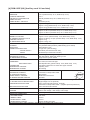
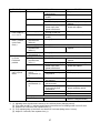
[d] DSM-12CE (UK) [Auxiliary code V-2 and later]
WATER CONSUMPTION PER 24h
SHAPE OF ICE
FREEZE CYCLE TIME
ICE PRODUCTION PER CYCLE
STORAGE CAPACITY
ICE DISPENSING RATE
DIMENSIONS
EXTERIOR
INSULATION
CONNECTIONS-ELECTRIC
-WATER SUPPLY
-DRAIN
ICE MAKING SYSTEM
HARVESTING SYSTEM
ICE DISPENSING SYSTEM
COMPRESSOR
CONDENSER
HEAT REJECTION
EVAPORATOR
REFRIGERANT CONTROL
REFRIGERANT CHARGE
ICE MAKING CONTROL
HARVESTING CONTROL
ICE STORAGE CONTROL
WATER SUPPLY CONTROL
ICE MAKING WATER CONTROL
ELECTRICAL PROTECTION
P.C. BOARD CIRCUIT PROTECTION
COMPRESSOR PROTECTION
1 PHASE 220-240V 50Hz
1.6 A (Ambient temp. 32 °C, Water temp. 21°C)
7.5 A
260 W (Ambient temp. 32°C, Water temp. 21°C)
68%
0.49 kVA (2.0 A)
Approx. 13 kg (Ambient temp. 10°C, Water temp. 10°C)
Approx. 10 kg (Ambient temp. 21°C, Water temp. 15°C)
Approx. 8 kg (Ambient temp. 32°C, Water temp. 21°C)
Approx. 0.097 m3 (Ambient temp. 10°C, Water temp. 10°C)
Approx. 0.081 m3 (Ambient temp. 21°C, Water temp. 15°C)
Approx. 0.065 m3 (Ambient temp. 32°C, Water temp. 21°C)
Shuttle
Approx. 12 min (Ambient temp. 21°C, Water temp. 15°C)
Approx. 0.085 kg / 27 pcs. (Ambient temp. 21°C, Water temp. 15°C)
Approx. 3 kg
Approx. 700 g / min
180 mm(W) × 510 mm(D) × 695 mm(H)
Acrylic Baked Steel (Cabinet), ABS Molding (Front Panel)
Polyurethane Foam
Y-Type Con. (with UK Plug)
lnlet G3/4 (Connected at rear side)
Outlet Rl/2 (Connected at rear side)
Mandrel type, Water agitated by plate
Hot Gas Defrost, Water Pan tilted by motor
Auger driven by Push Switch
Hermetic 125W Model TL4F
Air-cooled, Fin and Tube type
300 W{258 kcal/h} (Ambient temp. 32°C, Water temp. 21°C)
Tin-plated copper tube on sheet with copper mandrel
Capillary Tube
R134a 65g
Ice thickness measurement
AVERAGE SIZE OF ICE (mm)
Thermistor on Evaporator Outlet
φ23
約φ23
Microswitch
Water Pan's movement
14
Overflow
Class I Appliance, 5A Fuse 13A Fuse built in UK Plug
High Voltage Cut–out (Internal)
Auto–reset Overload Protector (Internal)
Thermistor on Evaporator Outlet (negative pressure protection)
Auto-reset Thermal Protector
Net Weight 23 kg / Gross Weight 26 kg
Carton 244 mm(W) × 584 mm(D) ×748 mm(H)
Mounting Brace, Installation Kit
約14
AC SUPPLY VOLTAGE
AMPERAGE
STARTING AMPERAGE
ELECTRICAL CONSUMPTION
POWER FACTOR
POWER SUPPLY CAPACITY
ICE PRODUCTION PER 24h
GEAR MOTOR PROTECTION
WEIGHT
PACKAGE
ACCESSORIES
OPERATION CONDITIONS
VOLTAGE RANGE
198-254V
AMBIENT TEMP.
5-40°C
WATER SUPPLY TEMP.
5-35°C
WATER SUPPLY PRESS.
0.05-0.78 MPa (0.5-8bar)
We reserve the right to make changes in specifications and design without prior notice.
6
II. GENERAL INFORMATION
1. CONSTRUCTION
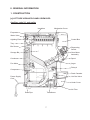
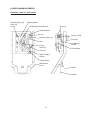
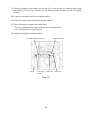
[a] LEFT SIDE VIEW WITH PANELS REMOVED
Auxiliary code V-1 and earlier
Insulation
Mechanism Cover
Evaporator
Water Valve
Agitating Plate
Control Box
Tray
Bin Sensor
Dispensing
Switch
Storage Bin
Gear Motor
Assembly
Condenser
Spout
Fan Motor
Auger
Relay-4
Compressor
Drain Cassette
Power Supply
Cord
Hot Gas Valve
Under Cover
Air Filter
Drain Pipe
Transformer
7
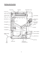
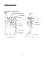
Auxiliary code V-2 and later
Thermistor
Insulation
Mechanism Cover
Evaporator
Water Valve
Agitating Plate
Control Box
Tray
Bin Sensor
Dispensing
Switch
Storage Bin
Gear Motor
Assembly
Condenser
Spout
Fan Motor
Auger
Compressor
Drain Cassette
Power Supply
Cord
Hot Gas Valve
Under Cover
Air Filter
Drain Pipe
Transformer
(Transformer-2)
8
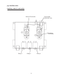
[b] CONTROL BOX
Auxiliary code V-1 and earlier
Defrost Thermostat
Fuse Holder
(250V/5A Fuse)
Relay-1
Relay-2
9
Relay-3
Protective
Thermostat
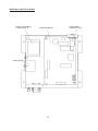
Auxiliary code V-2 and later
Power Transformer
(Transformer-1)
Controller Board
Power Relay
10
Fuse Holder
(250V/5A Fuse)
[c] MECHANISM ASSEMBLY
Auxiliary code V-1 and earlier
Retaining Ring (S)
Shim (B)
O-ring
Agitating Motor
Ice Making Switch Bracket
Shim (A)
Motor Bracket
Lever
Spring, Collar
Retaining Ring (L)
Arm
E-ring
Shim (C)
Cam (B)
Ice Making
Switch
Tilting Motor
Cam (A)
Water Supply
Switch
Tilting Switch
Mechanism
Cover
Guide
Shutter
11
Auxiliary code V-2 and later
Retaining Ring (S)
Shim (B)
O-ring
Agitating Motor
Ice Making Switch Bracket
Shim (A)
Motor Bracket
Lever
Spring, Collar
Retaining Ring (L)
Arm
E-ring
Shim (C)
Cam (B)
Ice Making
Switch
Tilting Motor
Cam (A)
Tilting Switch
Mechanism
Cover
Guide
Shutter
12
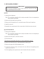
III. INSTALLATION AND OPERATING INSTRUCTIONS
WARNING
1.The installation must be carried out by qualified personnel, in accordance
with current regulations, according to the manufacturer’s instructions.
2.Keep ventilation openings, in the appliance enclosure or in the built-in
structure, clear of obstruction.
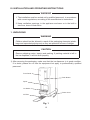
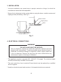
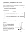
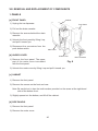
1. UNPACKING
WARNING
Children should not be allowed in reach of the packaging elements (plastic
bags and expanded polystyrene) as they are potential sources of danger.
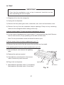
CAUTION
Remove shipping carton, tape(s) and packing. If packing material is left in
the ice dispenser, it will not work properly.
1)After removing the packaging, make sure that the ice dispenser is in good condition.
If in doubt, please do not use the equipment but apply to professionally qualified
personnel.
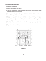
Front Panel
Spout
Ice Station
Air Filter
Fig. 1
13
Push Button
Power Cord
2)Remove shipping tapes holding the package of accessories, and check the contents:
a) Installation Kit
Inlet Hose
1
Outlet Hose
1
Rc1/2-G3/4 Nipple
1
b) Brace
1
c) Machine Screw
2
d) Tapping Screw
2
3)Remove tapes holding the power cord.
2. LOCATION
IMPORTANT
1. This ice dispenser is not intended for outdoor use. Normal operating
ambient temperature should be within 5°C to 40°C. Normal operating
water temperature should be within 5°C to 35°C. Operation of the ice
dispenser, for extended periods, outside of these normal temperature
ranges may affect production capacity.
2. The ice dispenser should not be located next to ovens, grills or other
high heat producing equipment.
3. The location should provide a firm and level foundation for the equipment
at normal counter top height.
4. Allow 15 cm clearance at rear and top and 5 cm at sides for proper
air circulation and ease of maintenance and/or service should they be
required.
5. This appliance is not suitable for installation in an area where a water jet
could be used and where dripping is not allowed.
6. Do not place anything on top of the ice dispenser or in front of the louver.
7.This ice dispenser will not work at subfreezing temperatures. To
prevent damage to the water supply line, drain the ice dispenser
when air temperature is below zero (see “IV. 2. PREPARING THE ICE
DISPENSER FOR LONG STORAGE”).
14
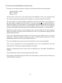
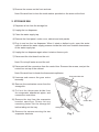
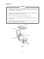
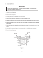
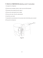
3. INSTALLATION
* Incorrect installation can cause harm to people, animals or things, for which the
manufacturer cannot be held responsible.
* Secure the ice dispenser to the counter table by using the brace, machine screws and
tapping screws (accessory). See Fig. 2.
Machine Screw
Tapping Screw
Brace
Counter Table
Fig. 2
4. ELECTRICAL CONNECTIONS
WARNING
THIS APPLIANCE MUST BE EARTHED
This ice dispenser requires an earth that meets the national and local
electrical code requirements. To prevent possible severe electrical shock to
individuals or extensive damage to equipment, install a proper earth wire
to the ice dispenser. Remove the plug from the mains socket before any
maintenance, repairs or cleaning is undertaken.
* This appliance requires a separate 220 - 240VAC, 13A supply. The electrical supply
must be protected by a suitable circuit breaker.
* The main control box fuse is rated at 5A and should only be replaced by a qualified
service engineer.
* Usually an electrical permit and services of a licensed electrician are required.
15
For the U.K. and the Republic of Ireland only
* The wires in the mains lead are coloured in accordance with the following code:
Green & Yellow = Earth
Blue = Neutral
Brown = Live
As the colours of the wire in the mains lead of this appliance may not correspond with
the coloured markings identifying the terminals in your plug, proceed as follows:
The wire which is coloured Green-and-Yellow must be connected to the terminal in
or coloured Green or
the plug which is marked with the letter E or by the symbol
Green-and-Yellow. The wire which is coloured Blue must be connected to the terminal
which is marked with the letter N or coloured Black. The wire which is coloured Brown
must be connected to the terminal which is marked with the letter L or coloured Red.
* Should the socket outlets in the installation site not be suitable for the plug supplied
with your product, the plug must be removed (cut off if it is moulded on plug) and an
appropriate plug fitted.
If the non-rewirable plug has been cut from the power supply cord, it must be
disposed of. There should be no attempt to reuse it. Inserting such a plug into a socket
elsewhere presents a serious risk of electrical shock.
* The non-rewirable plug must never be used without a fuse cover being fitted.
The correct replacement for the detachable fuse cover is identifiable from the
manufacturer’s reference number stamped on the plug.
Supply of replacement fuse covers can be obtained from Hoshizaki Parts/Service
Centres.
Fuses should be rated at 13A and approved to BS 1362.
* If the supply cord and the plug should need to be replaced, it should only be done by a
qualified service engineer.
16
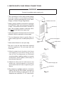
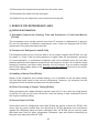
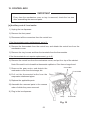
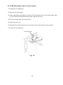
5. WATER SUPPLY AND DRAIN CONNECTIONS
WARNING
Connect to potable water supply only.
* The connections to the mains water supply
must be made in accordance with the
countries’ current requirements of the Water
Supply or Water Fittings Regulations.
Water Inlet G3/4
*Water supply pressure should be minimum
0.05 MPa (0.5 bar) and maximum 0.78 MPa
(8 bar). If the pressure exceeds 0.78 MPa (8
bar), use a proper pressure reducing valve.
Do NOT throttle back the supply tap.
Inlet Hose
* A plumbing permit and services of a licensed
plumber may be required in some areas.
* The ice dispenser drain is gravity flow, so
ensure drain pipe has an adequate pitch or
fall.
* Water should drain into an open trap.
*Be sure to use the new hose-sets supplied
with the appliance. Do not reuse any old
hose-sets.
Rc1/2-G3/4 Nipple
Drain Outlet
R1/2
Outlet Hose
Fig. 3
1)Attach angled end of white inlet hose
(accessory) to the G3/4 fitting on the
rear of the ice dispenser as indicated
ensuring rubber sealing washer is correctly
positioned. Hand tighten sufficiently to
provide leak free joint.
2)Attach the other end of inlet hose to the
water tap, noting washer is correctly
positioned before hand tightening as
above.
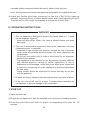
3)By means of a suitable spanner or wrench,
tighten the Rc1/2-G3/4 nipple (accessory)
into the R1/2 fitting on the rear of the ice
dispenser as indicated. P.T.F.E. tape and/or
17
Water Supply Tap
Inlet Hose
Fig. 4
a suitable sealing compound should be used to obtain a leak free joint.
Note: Jointing compounds should be approved and suitable for potable water use.
4)Attach grey flexible outlet hose (accessory) to free end of Rc1/2-G3/4 nipple as
indicated, confirming fitment of rubber washer before finally hand tightening the joint.
This pipe can be cut to length as necessary to suit position of main drain.
IV. OPERATING INSTRUCTIONS
WARNING
1. This ice dispenser is designed to produce and store edible ice. To keep
the ice dispenser hygienic:
* Keep the grille clean. Clean it by using a neutral cleaner and rinse
thoroughly.
2. The use of any electrical equipment involves the observance of some
fundamental rules. In particular:
* Instances of high humidity and moisture increase the risk of electrical
short circuits and potential electrical shocks. If in doubt, disconnect the
ice dispenser.
* Do not pull the power cord in order to disconnect the ice dispenser
from the feed network.
* This appliance is not intended for use by persons (including children)
with reduced physical, sensory or mental capabilities, or lack of
experience and knowledge, unless they have been given supervision
or instruction concerning use of the appliance by a person responsible
for their safety.
*Young children should be supervised to ensure that they do not play
with the appliance.
3. All parts are factory-adjusted. Improper adjustments may result in failure.
4. If the unit is turned off, wait for at least 3 minutes before restarting the
ice dispenser to prevent damage to the compressor.
1. START UP
1)Open the water tap.
2)Plug in the ice dispenser to start the automatic and continuous icemaking process.
3)Press the push button and check for proper ice dispensing action after 30 - 60
minutes.
18
2. PREPARING THE ICE DISPENSER FOR LONG STORAGE
1)Dispense all ice from the storage bin.
2)Close the water tap. Remove the inlet hose from the water tap, and drain the hose.
3)Unplug the machine from power socket.
4)Replace plug in the power socket and after 30 seconds unplug it again. This will
automatically drain the water inside the machine.
V. MAINTENANCE
WARNING
1. Before carrying out any cleaning or maintenance operations, unplug the
ice dispenser from the electrical supply network.
2. This appliance must not be cleaned by use of a water jet.
3.To prevent possible damage, do not clean the plastic parts with water
above 40°C or in a dishwasher.
[1] Exterior and Ice Station
Wipe the exterior and ice station at least once per week with a clean, soft cloth. Use a
damp cloth containing a neutral cleaner to wipe off grease or dirt.
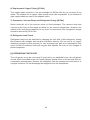
[2] Air Filter
Plastic mesh air filters remove dirt or dust
from the air, and keep the condenser from
getting clogged. If the filters get clogged,
the ice dispenser’s performance will be
reduced.
Remove and clean the air filter at least
twice per month by using a vacuum cleaner.
When severely clogged, use warm water
and a neutral cleaner to wash the air filter.
Rinse and dry the air filter thoroughly, and
place it in position.
Drain Cassette
Air Filter
Fig. 5
19
[3] Drain Cassette
At least once a week, pull out the drain cassette and clean it with warm water and a
neutral cleaner.
[4] Condenser
Check the condenser once a year, and clean if required by using a brush or vacuum
cleaner. More frequent cleaning may be required depending on the location of the ice
dispenser.
[5] Storage Bin Interior and Tray Cleaning/Sanitisation (as required)
IMPORTANT
Every time the mechanism cover or tray is removed, check the ice size
after assembling the removed parts.
1)Dispense all ice, and empty the storage bin.
2)Unplug the ice dispenser.
3)Remove the front panel.
4)Disconnect all the connectors from the control box. Remove the screws, and put the
control box on top of the cabinet.
Note: Be careful not to break the thermostat capillaries.
5)Unscrew and remove the gear motor assembly.
6)Remove the E-ring and shim (C), and take the arm off the cam (A) and lever.
7)Pull out the lever.
8)Remove the mechanism cover.
9)Remove the tray and auger.
10)Wash the storage bin, tray, auger and mechanism cover liner with a neutral nonabrasive cleaner. Rinse thoroughly.
Note: Do not splash water on the electrical parts on the surface of the mechanism
cover.
20
11)Mix 5 litres of water with 18 ml of 5.25% sodium hypochlorite solution in a suitable
container.
12)Soak a clean sponge or cloth with the solution, and wipe the storage bin, tray, auger
and mechanism cover liner.
13)Replace the removed parts in their correct position.
14)Plug in the ice dispenser.
Note: Do not wipe dry or rinse after sanitising, but allow to air dry.
21
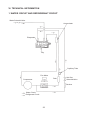
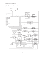
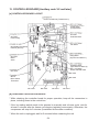
VI. TECHNICAL INFORMATION
1. WATER CIRCUIT AND REFRIGERANT CIRCUIT
Water Solenoid Valve
Accumulator
Evaporator
Tray
Capillary Tube
Fan Motor
Drier
Compressor
Hot Gas
Solenoid Valve
Strainer
Condenser
Water Circuit
Refrigerant Circuit
22
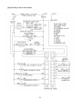
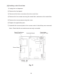
2. WIRING DIAGRAM
[a] Auxiliary code V-1 and earlier
23
[b] Auxiliary code V-2 and later
24
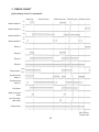
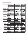
3. TIMING CHART
[a] Auxiliary code V-1 and earlier
Start Up
Michroswitch-2
Michroswitch-3
Michroswitch-4
Michroswitch-5
Freeze Cycle
Defrost Cycle Freeze Cycle Defrost Cycle
NO
NC
NO
NC
NO
NC
NO
NC
Relay-1
Relay-2
Relay-3
Relay-4
Thermostat-1
WARM
COLD
Synchronous
Motor-1
Synchronous
Motor-2
Fan Motor
Water Solenoid
Valve
Hot Gas Solenoid Valve
Compressor
Bin Control
Switch trips
25
[b] Auxiliary code V-2 and later
Part Name
Thermistor
Start Up
Freeze Cycle
Defrost Cycle
6°C
▲
Ice Making Switch
(Micro Switch-3)
ON
OFF
Compressor
Power Relay
ON
OFF
Hot Gas Solenoid
Valve
ON
OFF
Water Solenoid
Valve
ON
OFF
Fan Motor
ON
OFF
Tilting Switch
(Micro Switch-2)
ON
OFF
Tilting Motor
(Synchronous
Motor-1)
ON
OFF
Agitating Motor
(Synchronous
Motor-2)
ON
OFF
Bin Control Switch
(Micro Switch-4)
ON
OFF
15sec.
15-70sec.
Relay: X1
ON
(Compressor
OFF
Power Relay)
Relay: X2
ON
(Hot Gas
OFF
Solenoid Valve)
Relay: X3
(Water Solenoid ON
OFF
Valve)
Relay: X4
(Fan Motor)
ON
OFF
Relay: X5
(Tilting Motor)
ON
OFF
Relay: X6
ON
(Agitating Motor) OFF
26
■
Bin
Full
▲
0°C
●
Controller Board
Defrost
Cycle
Freeze Cycle
●
■
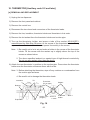
4. SEQUENCE
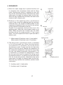
1)When the water supply tap is opened and the unit
is energized, the compressor starts and the tilting
motor (synchronous motor-1) operates to move the
tray into the horizontal position. Meanwhile the water
valve opens to supply ice making water into the tray.
When the tray reaches the horizontal, the water valve
closes to start a freeze cycle.
2)Rotation of the agitating motor (synchronous
motor-2) cam moves the agitating plate up and down
inside the tray to stir up the ice making water. As the
evaporator temperature falls, ice forms on the surface
of the projections immersed in the tray.
Growth of ice gradually obstructs the rise of the
agitating plate, while the motor bracket starts to go
down. When ice grows into a certain size, the motor
bracket hits the ice making switch [*1] as it goes
down. This will complete the freeze cycle and start a
defrost cycle.
*1 Michroswitch-5 [Auxiliary code V-1 and earlier]
Michroswitch-3 [Auxiliary code V-2 and later]
3)The tilting motor (synchronous motor-1) operates
to tilt the horizontal tray. When the tilting switch
(microswitch-2) operates, the tilting motor
(synchronous motor-1) stops and the hot gas valve
opens to flow hot gas for heating the evaporator. As
the evaporator temperature rises and ice drops from
the tray, the defrost thermostat (thermostat-1) [*2]
or thermistor [*3] senses the temperature to close
the hot gas valve and to operate the tilting motor
(synchronous motor-1) so that the tray will move back
into the horizontal position. Meanwhile the water
valve opens to supply ice making water into the tray.
When the tray reaches the horizontal, another freeze
cycle starts.
*2 Auxiliary code V-1 and earlier
*3 Auxiliary code V-2 and later
27
1)
Evaporator
Tray
2)
Cam (B)
Agitating Plate
Cam (B)
Ice Making Switch
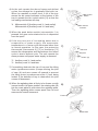
4)As the unit repeats the above freeze and defrost
cycles, the storage bin is gradually filled with ice.
When ice reaches a certain level, a tilt of the tray
moves the bin control activator at the bottom of the
tray to operate the bin control switch [*4] so that the
ice making mechanism will stop.
4)
Bin Control
Switch
*4 Michroswitch-3 [Auxiliary code V-1 and earlier]
Michroswitch-4 [Auxiliary code V-2 and later]
Bin Control
Activator
5)When the push button switch (microswitch-1) is
pressed, the gear motor starts and ice is dispensed
from the spout.
6)If the tray runs out of ice making water due to
s u s p e n s i o n o f w a t e r s u p p l y, t h e e v a p o r a t o r
temperature in a freeze cycle becomes lower than
in normal operation. In this case, the protective
thermostat (thermostat-2) [*5] or thermistor [*6]
senses the temperature and discontinues the freeze
cycle to start a defrost cycle. The unit repeats the
same process until proper water supply is resumed.
7)
Lever
Arm
Cam (A)
*5 Auxiliary code V-1 and earlier
*6 Auxiliary code V-2 and later
7)If something obstructs the rise of tray and the tilting
motor (synchronous motor-1) keeps running, the joint
of cam (A) and arm comes off upward to prevent
the tilting motor (synchronous motor-1) from being
locked. If the descent of tray is obstructed, the joint
comes off downward.
8)When the agitating plate is likely to be frozen up with
ice and stuck in its upper position, the rotating cam (B)
hits the reset plate to push down the agitating plate.
Then the agitating plate comes apart from ice and
resumes its normal movement.
8)
Frozen up
Reset Plate
28
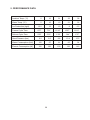
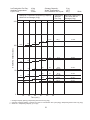
5. PERFORMANCE DATA
Ambient Temp. (°C)
5
10
21
32
38
Water Temp. (°C)
5
10
15
21
32
Ice Production (kg/d)
13.5
13
10
8
6.5
Freeze Cycle Time
6’57”
7’51”
10’16”
13’27”
16’41”
Defrost Cycle Time
2’56”
2’23”
1’58”
1’44”
1’37”
Head Pressure (bar)
6.2
6.5
9.8
13.4
15.5
Water Consumption (lit/d)
100
97
81
65
54
Electric Consumption (W)
125
126
130
136
146
29
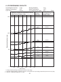
6. ICE DISPENSING CAPACITY
Ice Production Per Day:
Ambient Temperature:
Cycle Time:
13 kg
10°C
9.5 min.
Storage Capacity:
Water Temperature:
Ice Production Per Cycle:
Dispensing
Amount
Per Cup
Maximum Continuous Dispensing Capacity
With Full Ice Storage (3 kg)
3 kg
10°C
85 g
50Hz
Minimum Dispensing
Time With No Ice
Storage (0 kg)
150
111
108
Dispensing Capacity (cups)
100
102
100*
67
66
50
117**
69
73
71
75
77
57
58
52
53
41
42
43
39
40
33
34
30
32
35
31
26
28
29
25
51
50
38
10
30 g
9.5 min.
45 g
9.5 min.
60 g
9.5 min.
80 g
9.5 min.
100 g
19 min.
120 g
19 min.
(30 sec.***)
104
54
37
0
114
20
27
30
40
Time (min.)
50
* = Storage Capacity (3000g) / Dispensing Amount Per Cup (30g)
(46 sec.)
(62 sec.)
(83 sec.)
(102 sec.)
(124 sec.)
60
** ={Storage Capacity (3000g) + Number of Cycles x Ice Production Per Cycle (85g)} / Dispensing Amount Per Cup (30g)
*** =3600 sec. / Dispensing Capacity (117 cups)
30
Ice Production Per Day:
Ambient Temperature:
Cycle Time:
10 kg
21°C
12 min.
Storage Capacity:
Water Temperature:
Ice Production Per Cycle:
Dispensing
Amount
Per Cup
Maximum Continuous Dispensing Capacity
With Full Ice Storage (3 kg)
3 kg
15°C
85 g
50Hz
Minimum Dispensing
Time With No Ice
Storage (0 kg)
150
111**
108
Dispensing Capacity (cups)
100
50
0
102
100*
69
73
71
67
50
51
52
53
54
39
40
41
37
38
30
31
32
33
25
26
20
12 min.
104
66
10
30 g
(32 sec.***)
30
40
Time (min.)
* = Storage Capacity (3000g) / Dispensing Amount Per Cup (30g)
12 min.
60 g
12 min.
80 g
12 min.
100 g
24 min.
120 g
24 min.
(66 sec.)
(87 sec.)
(109 sec.)
27
50
45 g
(49 sec.)
(133 sec.)
60
** ={Storage Capacity (3000g) + Number of Cycles x Ice Production Per Cycle (85g)} / Dispensing Amount Per Cup (30g)
*** =3600 sec. / Dispensing Capacity (111 cups)
31
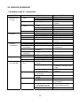
VII. SERVICE DIAGNOSIS
1. Auxiliary code V-1 and earlier
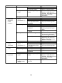
PROBLEM
[1] The ice
dispenser will
not start.
POSSIBLE CAUSE
a) Power supply
1. Open circuit.
cord
2. Loose connection.
3. Unplugged.
b) Fuse
1. Blown out.
c) Bin control
switch
[2] Compressor will
not start.
d) Relay-1
a) Starting relay
b) Start capacitor
c) Compressor
d) Relay-4
[3] Compressor
operates
intermittently.
a) Supply voltage
b) Starting relay
c) Ambient
temperature
d) Installation
[4] Fan will not turn.
e) Air filter,
condenser
f) Fan
a) Fan
[5] Water supply is
off or too little.
b) Fan motor
a) Water supply
line
b) Water circuit
c) Water valve
d) Microswitch-4
1. Microswitch-3 contacts
fused.
2. Sensor damaged.
3. Sensor out of position.
1. Bad contacts.
1. Open circuit.
2. Bad contacts.
1. Defective.
1. Coil winding opened.
1. Bad contacts.
1. Too high or too low.
1. Defective.
1. Too high or too low.
1. Vent (air inlet or outlet)
blocked.
1. Clogged.
1. Fan not rotating.
1. Fan blades blocked.
2. Fan out of position.
1. Coil winding opened.
1. Water supply tap
closed.
2. Water supply cut off.
3. Water supply pressure
too high or too low.
1. Water leaks from
connections.
2. Clogged with foreign
matter.
1. Clogged filter.
2. Coil winding opened.
1. Inoperative with
microswitch-4 or cam
(A) not fixed securely.
2. Bad contacts.
32
REMEDY
1. Replace.
2. Reconnect.
3. Plug in.
1. Check for continuity and
replace.
1. Replace.
2. Replace.
3. Place in position.
1. Replace.
1. Replace.
2. Replace.
1. Replace.
1. Replace.
1. Check for continuity and
replace.
1. Get recommended voltage.
1. Replace.
1. Get recommended
temperature.
1. Unblock.
1. Clean.
1. See [4].
1. Unblock
1. Place in position.
1. Replace.
1. Open.
1. Unplug the ice dispenser
and wait for resumed water
supply.
3. Get recommended
pressure.
1. Repair.
2. Clean.
1. Clean.
2. Check for proper voltage
and replace.
1. Fix in place and check for
proper switching action.
2. Replace.
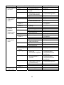
PROBLEM
[6] Water supply
never stops or is
too much.
[7] Tray will not go
down. (Freeze
cycle never
ends.)
[8] Tray will not go
up to the
horizontal
position.
(Defrost cycle
never ends.)
[9] Tray keeps on
going up and
down.
[10] Hot gas will not
flow or stop.
POSSIBLE CAUSE
a) Water supply
1. Water supply pressure
line
too high or too low.
b) Water valve
1. Clogged with foreign
matter.
1. Inoperative with
c) Microswitch-4
microswitch-4 or cam
(A) not fixed securely.
2. Bad contacts.
a) Relay-2, relay-3 1. Bad contacts.
b) Microswitch-5
1. Fused contacts.
2. Fixed too low and
cannot be switched on.
c) Synchronous
1. Coil winding opened.
Motor-1
d) Synchronous
1. Agitating motor not
Motor-2
running.
a) Relay-2, relay-3 1. Bad contacts.
2. Coil winding opened.
b) Thermostat-1
1. Bad contacts.
2. Gas leak from
thermostat bulb.
c) Hot gas
1. Will not flow.
1. Coil winding opened.
d) Synchronous
motor-1
2. Gear broken.
a) Microswitch-5
1. Bad contacts.
2. Fixed too high and
easily switched off.
b) Thermostat-2
1. Bad contacts.
2. Gas leak from
thermostat bulb.
c) Relay-3
1. Bad contacts.
d) Icemaking water 1. Too little.
supply
e) Agitating plate
1. Obstructed in rising
action and
microswitch-5 operates.
REMEDY
1. Get recommended
pressure.
1. Replace.
1. Fix in place and check for
proper switching action.
2. Replace.
1. Replace.
1. Replace.
2. Fix in proper position.
1. Check for proper voltage
and replace.
1. See [12].
1. Replace.
2. Replace.
1. Replace.
2. Replace.
1. See [10].
1. Check for proper voltage
and replace.
2. Replace.
1. Replace.
2. Fix in proper position.
1. Replace.
2. Replace.
1. Replace.
1. See [5].
1. Keep away from
surrounding parts
(refrigerant lines and
thermostat).
1. Keep away from
surrounding parts
(refrigerant lines and
thermostat).
1. Fix in place and check for
proper switching action.
f) Cam (B)
1. Obstructed in rotation
and microswitch-5
operates.
g) Microswitch-2
1. Inoperative with the
switch itself or cam (A)
not fixed securely.
2. Bad contacts.
1. Gear broken.
2. Replace.
1. Replace.
1. Coil winding opened.
2. Defective.
1. Replace.
2. Replace.
h) Synchronous
motor-1
a) Hot gas valve
33
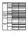
PROBLEM
[11] Tray starts to
go up with
remaining ice.
[12] Agitating motor
will not run.
[13] Agitating motor
stops in a
wrong position.
[14] Ice dispenser
will not stop
when bin is
filled with ice.
[15] Defective ice
[16] No ice is
dispensed with
push button
pressed.
POSSIBLE CAUSE
a) Thermostat-1
1. Fused contacts.
2. Thermostat bulb out of
position.
b) Relay-2
1. Fused contacts.
2. Coil winding opened.
c) Evaporator
1. Burrs or foreign matter.
2. Deformed.
d) Tray,
1. Deformed.
agitating plate
e) Microswitch-2
1. Cannot be switched on
with the switch itself or
cam (A) not fixed
securely.
2. Fused contacts.
f) Microswitch-5
1. Not fixed securely,
causing ice bridges.
a) Synchronous
1. Gear broken.
motor-2
2. Coil winding opened.
b) Relay-2
1. Bad contacts.
a) Relay-3
1. Bad contacts.
b) Microswitch-5
1. Not fixed securely and
inoperative.
a) Microswitch-3
1. Bad contacts.
2. Loose connection.
3. Open circuit.
1. Coil winding opened.
b) Relay-1
2. Fused contacts.
a) Tray
1. Deformed or damaged.
2. Obstructed from
horizontal position.
b) Refrigeration
1. Undercharged or gas
circuit
leaks
c) Icemaking water
supply
a) Microswitch-1
b) Dispensing
motor
1. Too little.
1. Loose connection.
2. Bad contacts.
3. Not fixed securely or
fixed part deformed or
damaged.
1. Coil winding opened.
2. Gear broken.
3. Thermal protector
operates.
4. Fails to start at low
voltage.
34
REMEDY
1. Replace.
2. Fix on evaporator.
1. Replace.
2. Replace.
1. Clean.
2. Repair or replace.
1. Repair or replace.
1. Fix in place and check for
proper switching action.
2. Replace.
1. Fix in place.
1. Replace.
2. Replace.
1. Replace.
1. Replace.
1. Fix in place.
1. Replace.
2. Reconnect.
3. Repair.
1. Replace.
2. Replace.
1. Replace.
2. Remove obstacles (capillary
tubes or refrigerant lines).
1. Check for leaks by leakage
detector. Weld leaks and
recharge. Gas leaks from
low side require thorough
evacuation.
1. See [5].
1. Reconnect.
2. Replace.
3. Repair or replace and check
for proper switching action.
1. Replace.
2. Replace.
3. Reset automatically when
winding temperature goes
down.
4. Adjust voltage.
PROBLEM
[16] (Continued)
POSSIBLE CAUSE
c) Storage bin
1. Little ice storage.
2. Ice bridges.
[17] Ice keeps on
being
dispensed.
[18] Abnormal noise
[19] Low or no ice
production
d) Screw
a) Microswitch-1
a) Fan motor
b) Dispensing
motor
c) Screw
a) Refrigeration
circuit
b) Drier,
capillary tubes,
strainer
1. Deformed or damaged.
1. Fused contacts.
2. Not fixed securely or
fixed part deformed or
damaged.
1. Bearing worn out.
1. Bearing worn out.
2. Gear worn out or
damaged.
1. Deformed or damaged.
1. Undercharged or gas
leaks
1. Clogged with moisture
or dirt.
35
REMEDY
1. A small amount of
remaining ice cannot be
dispensed. Wait for enough
ice storage.
2. Long suspension of ice
dispensing may cause ice
bridges. Instruct the user to
dispense everyday.
1. Repair or replace.
1. Replace.
2. Repair or replace and check
for proper switching action.
1. Replace.
1. Replace.
2. Replace.
1. Repair or replace.
1. Check for leaks by leakage
detector. Weld leaks and
recharge. Gas leaks from
low side require thorough
evacuation.
1. Replace.
2. Auxiliary code V-2 and later
PROBLEM
[1] The ice
dispenser will
not start.
POSSIBLE CAUSE
a) Power supply
1. Open circuit.
cord
2. Loose connection.
3. Unplugged.
b) Fuse
1. Blown out.
c) Bin control switch
(microswitch-4)
d) Transformer
(transformer-2)
e) Power
transformer
(transformer-1)
f) Controller board
[2] Compressor will a) Starting relay
not start.
b) Start capacitor
c) Compressor
d) Power relay
e) Controller board
[3] Compressor
operates
intermittently.
[4] Fan will not
turn.
a) Supply voltage
b) Start capacitor
c) Ambient
temperature
d) Installation
e) Air filter,
condenser
f) Fan
a) Fan
b) Fan motor
c) Controller board
[5] Water supply is
off or too little.
a) Water supply line
1. Microswitch-4 contacts
fused or short circuit.
2. Sensor damaged.
3. Sensor out of position.
1. Open circuit (including
built-in fuse operation).
1. Open circuit (including
built-in fuse operation).
1. Defective (no output).
Check input from
power transformer.
1. Open circuit.
2. Bad contacts.
1. Defective.
1. Coil winding opened.
See [3].
1. Bad contacts.
1. Defective (no output).
Check input from
power transformer.
1. Too high or too low.
1. Defective.
1. Too high or too low.
1. Vent (air inlet or outlet)
blocked.
1. Clogged.
1. Fan not rotating.
1. Fan blades blocked.
2. Fan out of position.
1. Coil winding opened.
1. Defective (no output).
Check input from
power transformer.
1. Water supply tap
closed.
2. Water supply cut off.
3. Water supply pressure
too high or too low.
36
REMEDY
1. Replace.
2. Reconnect.
3. Plug in.
1. Check for continuity and
replace.
1. Replace.
2. Replace.
3. Place in position.
1. Check for output (approx.
100V±15%) and replace.
1. Check for output (approx.
11V±15%) and replace.
1. Check for output to LED on
board and replace.
1. Replace.
2. Replace.
1. Replace.
1. Check for continuity and
replace.
1. Check for continuity and
replace.
1. Check for output to LED on
board and replace.
1. Get recommended voltage.
1. Replace.
1. Get recommended
temperature.
1. Unblock.
1. Clean.
1. See [4].
1. Unblock
1. Place in position.
1. Check for proper voltage and
replace.
1. Check for output to LED on
board and replace.
1. Open.
1. Unplug the ice dispenser and
wait for resumed water
supply.
3. Get recommended pressure.
PROBLEM
[5] (Continued)
POSSIBLE CAUSE
b) Water circuit
1. Water leaks from
connections.
2. Clogged with foreign
matter.
c) Water valve
1. Clogged filter.
2. Coil winding opened.
d) Controller board
[6] Water supply
never stops or
is too much.
a) Water supply line
[7] Tray will not go
down. (Freeze
cycle never
ends.)
a) Agitating motor
(synchronous
motor-2)
b) Water supply
c) Tilting motor
(synchronous
motor-1)
d) Bin control switch
(microswitch-4)
a) Hot gas valve
b) Tilting motor
(synchronous
motor-1)
c) Controller board
[8] Tray will not go
up to the
horizontal
position.
[9] Tray keeps on
going up and
down.
b) Water valve
a) Ice making
switch
(microswitch-3)
*1
b) Connector (7P)
*2
c) Tilting switch
(microswitch-2)
*2
d) See [5].
e) Agitating plate
*1: (1)
(2)
(3)
*2: (1)
(2)
1. Defective (no output).
Check input from
power transformer.
1. Water supply pressure
too high or too low.
1. Clogged with foreign
matter.
1. See [12].
1. See [5].
1. Coil winding opened.
REMEDY
1. Repair.
2. Clean.
1. Clean.
2. Check for proper voltage and
replace.
1. Check for output to LED on
board and replace.
1. Get recommended pressure.
1. Clean.
1. Check for proper voltage and
replace.
1. See [14].
1. See [10].
1. Coil winding opened.
2. Gear broken. See [19].
1. Defective (no output).
Check input from
power transformer.
1. Fused contacts.
2. Not fixed securely and
inoperative.
1. Disconnected (control
box bottom).
1. Switch terminal
disconnected.
2. Switch or cam (A) not
fixed securely and
inoperative.
3. Bad contacts.
4. Fused contacts.
1. Obstructed.
1. Check for proper voltage and
replace.
2. Replace.
1. Check for output to LED on
board and replace.
1. Replace.
2. Fix in proper position.
1. Reconnect.
1. Reconnect.
2. Fix securely and check for
proper switching action.
3. Replace.
4. Replace.
1. Remove obstacles (capillary
tubes or refrigerant lines).
Agitating motor (synchronous motor-2) runs with tray down (banging sound).
Tray goes up after 1.5 minutes, and freeze cycle starts but ice making switch turns off soon.
Stays off for 5 minutes, then repeats from (1).
Tray repeats going up and down two times for 2 minutes (tilting motor: 2 turns).
Stops for 5 minutes, then repeats from (1).
37
PROBLEM
[9] (Continued)
[10] Hot gas will
not flow or
stop.
f) Cam (B)
POSSIBLE CAUSE
1. Obstructed.
g) Agitating motor
(synchronous
motor-2)
h) See [11].
a) Connector (7P)
*3
b) Thermistor
*3
c) Hot gas valve
d) Controller board
[11] Tray starts to
go up with
remaining ice,
causing ice
bridges.
e) See [11].
a) Ice making
switch
(midroswitch-3)
b) Thermistor
c) Evaporator
d) Tray,
agitating plate
e) Tilting switch
(microswitch-2)
[12] Agitating
motor will not
run.
[13] Agitating
motor stops in
a wrong
position.
[14] Ice dispenser
will not stop
when bin is
filled with ice.
f) See [13].
a) Agitating motor
(synchronous
motor-2)
b) Controller board
a) Ice making
switch
(midroswitch-3)
a) Bin control switch
(microswitch-4)
b) Bin sensor
1. Gear broken. See [19].
REMEDY
1. Remove obstacles (capillary
tubes or refrigerant lines).
1. Replace.
1. Disconnected in freeze
cycle (control box
bottom).
1. Not fixed securely on
evaporator outlet pipe.
2. Open or short circuit.
1. Coil winding opened.
2. Defective.
1. Defective (no output).
Check input from
power transformer.
1. Reconnect.
1. Loose connection.
2. Open circuit.
3. Not fixed securely and
inoperative.
4. Bad contacts.
1. Not fixed securely on
evaporator outlet pipe.
1. Burrs or foreign matter.
2. Deformed.
1. Deformed.
1. Reconnect.
2. Repair.
3. Fix in proper position.
1. Switch or cam (A) not
fixed securely and
inoperative.
2. Fused contacts.
1. Fix securely and check for
proper switching action.
2. Replace.
1. Gear broken.
2. Coil winding opened.
1. Replace.
2. Replace.
1. Defective (no output).
Check input from
power transformer.
1. Not fixed securely and
inoperative.
1. Check for output to LED on
board and replace.
1. Not fixed securely on
Tray.
2. Loose connection.
3. Open circuit.
4. Bad contacts.
1. Not fixed securely.
2. Broken.
1. Fix securely.
1. Fix securely.
2. Replace.
1. Replace.
2. Replace.
1. Check for output to LED on
board and replace.
4. Replace.
1. Fix securely.
1. Clean.
2. Repair or replace.
1. Repair or replace.
1. Fix in proper position.
2. Reconnect.
3. Repair.
4. Replace.
1. Fix securely.
2. Replace.
*3: (1) Hot gas valve opens and closes after 10 minutes when timer counts up.
(2) Stays closed for 5 minutes, then repeats from (1).
38
PROBLEM
[15] Defective ice
[16] No ice is
dispensed
with push
button
pressed.
POSSIBLE CAUSE
a) Tray
1. Deformed or damaged.
2. Obstructed from
horizontal position.
b) Refrigeration
1. Undercharged or gas
circuit
leaks
c) See [5].
a) Dispensing
switch
(microswitch-1)
b) Dispensing motor
c) Storage bin
1. Loose connection.
2. Bad contacts.
3. Not fixed securely or
fixed part deformed or
damaged.
1. Coil winding opened.
2. Gear broken.
3. Thermal protector
operates.
4. Fails to start at low
voltage.
1. Little ice storage.
2. Ice bridges.
[17] Ice keeps on
being
dispensed.
d) Screw
a) Dispensing
switch
(microswitch-1)
[18] Abnormal
noise
a) Fan motor
b) Dispensing motor
[19] Low or no ice
production
c) Screw
a) Refrigeration
circuit
b) Drier,
capillary tubes,
strainer
1. Deformed or damaged.
1. Fused contacts.
2. Not fixed securely or
fixed part deformed or
damaged.
1. Bearing worn out.
1. Bearing worn out.
2. Gear worn out or
damaged.
1. Deformed or damaged.
1. Undercharged or gas
leaks
1. Clogged with moisture
or dust.
39
REMEDY
1. Replace.
2. Remove obstacles (capillary
tubes or refrigerant lines).
1. Check for leaks by leakage
detector. Weld leaks and
recharge. Gas leaks from low
side require thorough
evacuation.
1. Reconnect.
2. Replace.
3. Repair or replace and check
for proper switching action.
1. Replace.
2. Replace.
3. Reset automatically when
winding temperature goes
down.
4. Adjust voltage.
1. A small amount of remaining
ice cannot be dispensed.
Wait for enough ice storage.
2. Long suspension of ice
dispensing may cause ice
bridges. Instruct the user to
dispense everyday.
1. Repair or replace.
1. Replace.
2. Repair or replace and check
for proper switching action.
1. Replace.
1. Replace.
2. Replace.
1. Repair or replace.
1. Check for leaks by leakage
detector. Weld leaks and
recharge. Gas leaks from low
side require thorough
evacuation.
1. Replace.
VIII. REMOVAL AND REPLACEMENT OF COMPONENTS
1. PANELS
[a] FRONT PANEL
Cabinet
1)Unplug the ice dispenser.
Front Panel
2)Pull out the drain cassette.
3)Remove the screws behind the drain
cassette.
4)Unhook the front panel by lifting it up,
and pull it toward you.
5)Disconnect the connectors from the
push button switch.
Side Panel
[b] UNDER COVER
Under Cover
1)Remove the front panel. The upper
part of the under cover is screwed
with the front panel.
Drain Cassette
Fig. 6
2)Unhook the under cover by lifting it up and pull it toward you.
[c] CABINET
1)Remove the front panel.
2)Remove the screws on the front and rear.
Note:Be careful not to lose the tooth washer provided on the screw at the right-hand
side of the bottom front.
3)Slightly spread out the bottom, and lift off the cabinet.
[d] SIDE PANELS
1)Remove the front panel.
2)Remove the under cover.
40
3) Remove the screws on the front and rear.
Note: Be careful not to lose the tooth washer provided on the screw at the front.
2. STORAGE BIN
1)Dispense all ice from the storage bin.
2)Unplug the ice dispenser.
3)Close the water supply tap.
4)Remove the front panel, under cover, cabinet and side panels.
5)Plug in and run the ice dispenser. When it starts a defrost cycle, open the water
valve to reduce the water supply pressure inside the inlet hose located downstream
of the water supply tap.
6)Unplug the ice dispenser again when it starts a freeze cycle.
7)Disconnect the inlet hose from the unit.
Note: Do not spill water around the unit.
8)Disconnect all the connectors from the control box. Remove the screws, and put the
control box on top of the cabinet.
Note: Be careful not to break the thermostat capillaries.
Evaporator Bracket
9)Unscrew and remove the gear motor
assembly.
10)Remove the mechanism cover from the
storage bin.
11) Pull out the thermostat bulbs from
the evaporator attachment pipes, and
remove the control box.
12)Remove the tray from the evaporator
bracket openings. Dump out any
remaining water into the storage bin
before taking out the tray.
13)Remove the screws securing the two
evaporator brackets.
41
Control Box
Tray
Storage Bin
Fig. 7
14)Disconnect the hoses and terminals from the water valve.
15)Disconnect the hose from the drain pipe.
16)Slightly lift up the evaporator, and remove the storage bin.
3. SERVICE FOR REFRIGERANT LINES
[a] SERVICE INFORMATION
1) Allowable Compressor Opening Time and Prevention of Lubricant Mixture
[R134a]
The compressor must not be opened more than 30 minutes in replacement or service.
Do not mix lubricants of different compressors even if both are charged with R134a,
except when they uses the same lubricant.
2) Treatment for Refrigerant Leak [R134a]
If a refrigerant leak occurs in the low side of an ice maker charged with R134a, air may
be drawn in. Even if the low side pressure is higher than the atmospheric pressure
in normal operation, a continuous refrigerant leak will eventually lower the low side
pressure below the atmospheric pressure and will cause air suction. Air contains a large
amount of moisture, and ester easily absorbs a lot of moisture. If an ice maker charged
with R134a has possibly drawn in air, the drier must be replaced. Be sure to use a drier
designed for R134a.
3) Handling of Handy Flux [R134a]
Repair of the refrigerant circuit needs brazing. It is no problem to use the same handy
flux that has been used for the current refrigerants. However, its entrance into the
refrigerant circuit should be avoided as much as possible.
4) Oil for Processing of Copper Tubing [R134a]
When processing the copper tubing for service, wipe off oil, if any used, by using alcohol
or the like. Do not use too much oil and let it into the tubing, or wax contained in the oil
will clog the capillary tubing.
5) Service Parts for R134a
Some parts used for refrigerants other than R134a are similar to those for R134a. But
never use any parts unless they are specified for R134a because their endurance
against the refrigerant have not been evaluated. Also, for R134a, do not use any parts
that have been used for other refrigerants. Otherwise, wax and chlorine remaining on
the parts may adversely affect R134a.
42
6) Replacement Copper Tubing [R134a]
The copper tubes currently in use are available for R134a. But do not use them if oily
inside. The residual oil in copper tubes should be as little as possible. (Low residual oil
type copper tubes are used in the shipped units.)
7) Evacuation, Vacuum Pump and Refrigerant Charge [R134a]
Never allow the oil in the vacuum pump to flow backward. The vacuum level and
vacuum pump may be the same as those for the current refrigerants. However, the
rubber hose and gauge manifold to be used for evacuation and refrigerant charge
should be exclusively for R134a.
8) Refrigerant Leak Check
Refrigerant leaks can be detected by charging the unit with a little refrigerant, raising
the pressure with nitrogen and using an electronic detector. Do not use air or oxygen
instead of nitrogen for this purpose, or rise in pressure as well as in temperature may
cause R134a to suddenly react with oxygen and explode. Be sure to use nitrogen to
prevent explosion.
[b] REFRIGERANT RECOVERY
The refrigerant must be recovered if required by an applicable law. No refrigerant
access valve is provided in the unit. Install a proper access valve on the low-side line (ex.
compressor process pipe). Recover the refrigerant from the access valve and store it in
a proper container. Do not discharge the refrigerant into the atmosphere.
43
[c] EVACUATION AND RECHARGE
1)Attach charging hoses, a service manifold and a vacuum pump to the system.
2)Turn on the vacuum pump.
3)Allow the vacuum pump to pull down to a 760 mmHg vacuum. Evacuating period
depends on pump capacity.
4)Close a low-side valve on the service manifold.
5)Disconnect the vacuum pump, and attach a refrigerant service can. Remember to
loosen the connection, and purge the air from the hose. See the nameplate for the
required refrigerant charge.
6)Open the low-side valve. Do not invert the service can. A liquid charge will damage
the compressor.
7)Plug in the ice dispenser when charging speed gets slow. Unplug the ice dispenser
when the low-side gauge shows approximately 0 bar (0 MPa). Do not run the ice
dispenser at vacuum pressures. Close the low-side valve when the service can gets
empty.
8)Repeat steps 4) through 7), if necessary, until the required amount of refrigerant has
entered the system.
9)Close the refrigerant access valve, and disconnect the hoses and service manifold.
10)Cap the access valve to prevent a possible leak.
44
4. BRAZING
DANGER
1. Refrigerant R134a itself is not flammable, explosive and poisonous.
However, when exposed to an open flame, R134a creates phosgene
gas, hazardous in large amounts.
2. Always recover the refrigerant and store it in a proper container. Do not
discharge the refrigerant into the atmosphere.
3. Do not use silver alloy or copper alloy containing arsenic.
4. In its liquid state, the refrigerant can cause frostbite because of the low
temperature.
5. When repairing the refrigerant system, be careful not to let the burner
flame contact the lead wires or insulation.
Evaporator
Condenser
Drier
Compressor
Fan Motor
Fig. 8
45
5. DRIER
IMPORTANT
Always install a new drier every time the sealed refrigeration system is
opened. Do not replace the drier until after all other repair or replacement
has been made.
1)Unplug the ice dispenser.
2)Remove the panels.
3)Recover the refrigerant and store it in a proper container.
4)Remove the clamp securing the drier, and pull the drier toward you for easy service.
5)Remove the drier using brazing equipment.
6)Install the new drier in the direction of the refrigerant flow. Use nitrogen gas at the
pressure of 0.2 - 0.3 bar (0.02 - 0.03 MPa) when brazing the tubings.
7)Check for leaks using nitrogen gas [10 bar (1 MPa)] and soap bubbles.
8)Secure the drier with the clamp.
9)Evacuate the system, and charge it with refrigerant. See the nameplate for the
required refrigerant charge.
10)Replace the panels in their correct position.
11)Plug in the ice dispenser.
46
6. COMPRESSOR
1)Unplug the ice dispenser.
2)Remove the panels.
3)Remove the terminal cover on the compressor, and disconnect the compressor
wiring.
4)Recover the refrigerant and store it in a proper container.
5)Unsolder and disconnect the discharge and suction pipes from the compressor.
6)Remove the hold-down bolts, washers and rubber grommets.
7)Slide and remove the compressor. Unpack the new compressor package. Install the
new compressor.
8)Attach the rubber grommets of the previous compressor.
9)Sandpaper the suction, discharge and process pipes.
10)Place the compressor in position, and secure it using the bolts and washers.
11)Remove plugs from the suction, discharge and process pipes.
12)Braze the process, suction and discharge pipes (Do not change this order), with
nitrogen gas flowing at the pressure of 0.2 - 0.3 bar (0.02 - 0.03 MPa).
13)Replace the drier.
14)Check for leaks using nitrogen gas [10 bar (1 MPa)] and soap bubbles.
15)Connect the compressor wiring to the compressor, and replace the terminal cover in
its correct position.
16)Evacuate the system, and charge it with refrigerant. See the nameplate for the
required refrigerant charge.
17)Replace the panels in their correct position.
18)Plug in the ice dispenser.
47
7. HOT GAS VALVE
1)Unplug the ice dispenser.
2)Remove the panels.
3)Remove the screw securing the hot gas valve.
4)Remove the screw securing the coil to the valve body, and pull off the coil.
If the coil does not require replacement, go to 7).
5)Cut the coil leads at the wire connectors.
6)Install the new coil.
7)Recover the refrigerant and store it in a proper container.
8)Remove the hot gas valve using brazing equipment.
9)Install the new hot gas valve in the direction of the refrigerant flow. Use nitrogen gas
at the pressure of 0.2 - 0.3 bar (0.02 - 0.03 MPa) when brazing the tubings.
WARNING
Always protect the valve body by using a damp cloth to prevent the valve
from overheating. Do not braze with the valve body exceeding 120°C.
10)Check for leaks using nitrogen gas [10 bar (1 MPa)] and soap bubbles.
11)Evacuate the system and charge it with refrigerant. See the nameplate for the
required refrigerant charge.
12)Screw down the coil on the valve body, and secure it to the unit.
13)Replace the panels in their correct position.
14)Plug in the ice dispenser.
48
8. EVAPORATOR
1)Unplug the ice dispenser.
2)Remove the panels.
3)Remove the storage bin.
4)Recover the refrigerant and store it in a proper container.
5)Sandpaper and disconnect the brazing connection. Remove the evaporator using
brazing equipment.
6)Detach the two brackets from the removed evaporator, and attach them to the new
evaporator.
7)Install the new evaporator. Use nitrogen gas at the pressure of 0.2 - 0.3 bar (0.02 0.03 MPa) when brazing the tubings.
IMPORTANT
Always protect the evaporator pipe by using a damp cloth to prevent the
plating from coming off.
8)Check for leaks using nitrogen gas [10 bar (1 MPa)] and soap bubbles.
9)Evacuate the system, and charge it with refrigerant. See the nameplate for the
required refrigerant charge.
10)Replace the storage bin and panels in their correct position.
11)Plug in the ice dispenser.
9. FAN MOTOR
1)Unplug the ice dispenser.
2)Remove the front panel, cabinet, under cover and side panels.
3)Cut the fan motor leads at the wire connectors.
4)Remove the fan motor assembly from the condenser, and detach the bracket and
fan from the fan motor.
5) Install the new fan motor.
49
6) Assemble the removed parts in the reverse order of which they were removed.
7) Plug in the ice dispenser.
10. WATER VALVE
1)Unplug the ice dispenser.
2)Close the water supply tap.
3)Remove the front panel and cabinet.
4)Plug in and run the ice dispenser. When it starts a defrost cycle, open the water
valve to reduce the water supply pressure inside the inlet hose located downstream
of the water supply tap.
5)Unplug the ice dispenser again when it starts a freeze cycle.
6)Disconnect the inlet hose from the unit.
Note: Do not spill water around the unit.
7)Disconnect the hoses and terminals from the water valve.
8)Remove the two screws securing the water valve, and pull out the water valve from
the storage bin opening.
9)Install the new water valve.
10)Assemble the removed parts in the reverse order of which they were removed.
11)Open the water supply tap.
12)Plug in the ice dispenser.
13)Check for water leaks.
50
11. GEAR MOTOR
IMPORTANT
Do not reuse the spring pin. To prevent excessive strain, fix the gear motor
shaft when installing the spring pin.
1)Unplug the ice dispenser.
2)Remove the front panel.
3)Cut the gear motor leads at the wire connectors.
4)Remove the gear motor assembly from the mechanism cover.
5)Detach the spring pin from the gear motor shaft, and remove the gear motor bracket.
6)Attach the bracket to the new gear motor, and install a new spring pin on the gear
motor shaft.
7)Insert the gear motor assembly so that the spring pin will fit the slit at the end of the
auger.
8)Assemble the removed parts in the reverse order of which they were removed.
9)Plug in the ice dispenser.
Spring Pin
Bracket
Gear Motor
Fig. 9
51
12. CONTROL BOX
IMPORTANT
Every time the mechanism cover or tray is removed, check the ice size
after assembling the removed parts.
[a] Auxiliary code V-1 and earlier
1)Unplug the ice dispenser.
2)Remove the front panel.
3)Disconnect all the connectors from the control box.
If the thermostats require replacement, go to 6).
4)Remove the thermostats from the control box, and detach the control box from the
mechanism cover.
5)Remove the vinyl covers and then the terminals from the thermostats.
If the thermostats do not require replacement, go to 9).
6)Remove the control box from the mechanism cover, and put it on top of the cabinet.
Note:Be careful not to break the thermostat capillaries. Give them a large bend.
7)Remove the gear motor, and detach the
mechanism cover from the storage bin.
Control Box
Fuse Holder
8)Pull out the thermostat bulbs from the
evaporator attachment pipes.
9)Replace the applicable parts.
10)Assemble the removed parts in the reverse
order of which they were removed.
11)Plug in the ice dispenser.
Relay
Fig. 10
52
Thermostat
[b] Auxiliary code V-2 and later
1)Unplug the ice dispenser.
2)Remove the front panel.
3)Disconnect the three connectors from the control box.
4)Remove the four screws securing the control box, and remove the control box.
5)Remove the two screws securing the cover.
6)Replace the applicable parts.
7)Assemble the removed parts in the reverse order of which they were removed.
Note:Check that the connectors are securely connected.
Power Transformer
(Transformer-1)
Controller Board
Power Relay
Fig. 11
53
Fuse Holder
(250V/5A Fuse)
13. CONTROLLER BOARD [Auxiliary code V-2 and later]
[a] CONTROLLER BOARD LAYOUT
Power Transformer (Transformer-1)
Power Relay
(Compressor)
Hot Gas
Solenoid Valve
OUTPUT
Power Relay
(Synchronous Motor-2)
Fan Motor
Illuminates (energized)
Flashes (bin full)
Tilting Motor
(Synchronous Motor-1)
OUTPUT
Motor
Valve
Agitating Motor
(Synchronous Motor-2)
Water Solenoid Valve
Not used
Not used
INPUT
Micro Switch
Thermistor
Not used
Not used
Not used
Not used
Not used
[b] CHECKING CONTROLLER BOARD
*While checking the controller board for proper operation, keep all the connectors in
place, including those in the control box.
*If the ice making switch needs to be pressed to manually end a freeze cycle, wait for
at least 3 minutes after the freeze cycle begins (agitating motor starts). Otherwise, the
compressor will stop for 5 minutes (considered as low water condition).
*When the unit is unplugged, wait for 5 minutes before restarting the unit.
54
14. FUSE [Auxiliary code V-0 and earlier]
1) Unplug the ice dispenser.
2) Remove the front panel.
3) Insert a flat blade screwdriver or the like into the square hole on the fuse holder (side
or top). Push and unhook the fuse holder cap with the fuse.
4) Pull out the cap, and remove the fuse.
5) Install the new fuse.
6) Assemble the removed parts in the reverse order of which they were removed.
7) Plug in the ice dispenser.
Fuse Holder Cap
Fig. 12
55
15. MECHANISM ASSEMBLY
IMPORTANT
Every time the mechanism cover or tray is removed, check the ice size
after assembling the removed parts.
[a] ARM
1) Unplug the ice dispenser.
Note: The mechanism assembly will be easily removable if the unit is stopped just
after a defrost cycle starts.
2) Remove the front panel and control box.
3) Remove the E-ring and shim (C), and take the arm off the cam (A) and lever.
4) Install the new arm.
5) Assemble the removed parts in the reverse order of which they were removed.
[b] AGITATING MOTOR
1) Unplug the ice dispenser.
Note: The mechanism assembly will be easily removable if the unit is stopped just
after a defrost cycle starts.
2) Remove the front panel, control box and arm.
3) Pull out the lever.
If the shims (A), spring and collar does not require replacement, go to 5).
4) Remove the retaining ring (L), and disassemble the above parts.
5) Remove the gear motor and mechanism cover.
6) Loosen the securing screw, and remove the cam (B) from the agitating motor
(synchronous motor-2).
7) Cut the agitating motor (synchronous motor-2) leads at the wire connectors.
56
8) Remove the securing screw, and take off the agitating motor (synchronous motor-2).
If the shim (B) and O-rings do not require replacement, go to 10).
9) Remove the retaining ring (S), and disassemble the above parts.
10) Replace the parts as required.
11) Assemble the removed parts in the reverse order of which they were removed.
12) Plug in the ice dispenser.
[c] TILTING MOTOR
1) Unplug the ice dispenser.
Note: The mechanism assembly will be easily removable if the unit is stopped just
after a defrost cycle starts.
2) Remove the front panel, control box and arm.
If the cam (A) and tilting motor (synchronous motor-1) do not require replacement, go
to 7).
3) Loosen the securing screw, and remove the cam (A) from the tilting motor
(synchronous motor-1).
4) Cut the tilting motor (synchronous motor-1) leads at the wire connectors.
5) Remove the motor bracket from the mechanism cover.
6) Remove the tilting motor (synchronous motor-1) from the motor bracket.
[Auxiliary code V-1 and earlier]
If the tilting switch (michroswitch-2) [left] and water supply switch (michroswitch-4) [right]
do not require replacement, go to 9).
[Auxiliary code V-2 and later]
If the tilting switch (michroswitch-2) does not require replacement, go to 9).
7) Disconnect the terminals from the above switches.
8) Remove the switches from the motor bracket.
9) Replace the parts as required.
57
10) Assemble the removed parts in the reverse order of which they were removed.
11) Plug in the ice dispenser.
[d] ICE MAKING SWITCH [Auxiliary code V-1 and earlier]
1) Unplug the ice dispenser.
2) Remove the front panel, control box, arm and lever.
3) Disconnect the connectors from the ice making switch (michroswitch-5).
4) Remove the securing screw, and take off the ice making switch (michroswitch-5).
5) Install the new ice making switch (michroswitch-5).
6) Assemble the removed parts in the reverse order of which they were removed.
7) Plug in the ice dispenser.
[e] ICE MAKING SWITCH [Auxiliary code V-2 and later]
To remove:
1) Unplug the ice dispenser.
2) Remove the front panel and cabinet.
3)Disconnect all the connectors from the control box.
4)Unscrew and remove the control box.
5)Disconnect the connector from the ice making switch.
6)Check and remember the location of the ice making switch bracket. Remove the
hexagon head screw and screw (A). Take out the ice making switch together with
the bracket.
7)Remove the screw (B) and take the ice making switch off the bracket.
To replace:
8)Use the screw (B) to secure the ice making switch on the bracket.
58
Projection (Mandrel)
Evaporator
Agitating Plate
23 mm DIA or less
9)Use the hexagon
head screw and screw (A) to secure the ice making switch and
Tray
the bracket on the cover. Position
the ice making switch bracket around its original
location.
10)Plug the connector into the ice making switch.
11)Screw the control box and plug in the connectors.
12)Turn on the power supply and check that:
- The tray, agitating plate, lever and arm are not obstructed.
- Ice of the proper size is produced.
13)Replace the cabinet and front panel.
Ice Making Switch Bracket
Cover
Ice Making Switch
Screw (B)
Hex Head
Screw
Fig. 13
1
59
Screw (A)
16. TRAY
IMPORTANT
Every time the mechanism cover or tray is removed, check the ice size
after assembling the removed parts.
1)Dispense all ice from the storage bin.
2)Unplug the ice dispenser.
3)Remove the front panel, gear motor, control box, arm, lever and mechanism cover.
4)Remove the tray from the evaporator bracket openings. Dump out any remaining
water into the storage bin before taking out the tray.
If the bin control switch [*1] does not require replacement, go to 6).
5)Cut the nylon tie binding the bin control switch [*1] wiring with the tray shaft. Remove
the bin control switch [*1] by spreading out the tabs on both sides.
Note: Do not put excessive strain and break the tabs or pins.
If the bin sensor does not require replacement, go to 7).
6)Remove the rear shaft of the bin sensor first and then the front shaft.
If the agitating plate does not require replacement, go to 8).
7)Pull out the pin, and remove the agitating
plate.
8)Replace the parts as required.
9)Assemble the removed parts in the reverse
order of which they were removed.
10)Plug in the ice dispenser.
Bin Control
Switch
Agitating Plate
*1 Michroswitch-3 [Auxiliary code V-1 and earlier]
Michroswitch-4 [Auxiliary code V-2 and later]
60
Tray
Fig. 14
Bin Sensor
17. RELAY-4 (COMPRESSOR) [Auxiliary code V-1 and earlier]
1) Unplug the ice dispenser.
2) Remove the front panel, cabinet, under cover and left side panel.
3) Disconnect the terminals from the relay-4.
4) Remove the relay bracket from the base.
5) Remove the relay-4 from the relay bracket.
6) Install the new relay-4.
7) Assemble the removed parts in the reverse order of which they were removed.
8) Plug in the ice dispenser.
Relay-4
Fig. 15
61
18. THERMISTOR [Auxiliary code V-2 and later]
[a] REMOVAL AND REPLACEMENT
1) Unplug the ice dispenser.
2)Remove the front panel and cabinet.
3)Remove the control box.
4)Disconnect the two closed end connectors of the thermistor leads.
5)Remove the ties, insulation, thermistor holder and thermistor in this order.
6)Remove the old sealant from the thermistor holder and suction pipe.
7)Turn up the thermistor holder, and press a tube of the sealant KE4560RTV,
manufactured by Shin-Etsu Silicones, to the recess of the thermistor holder. Slowly
squeeze the sealant out of the tube and spread it smoothly in the recess.
Note: 1.Be careful not to let in air and make a hollow in the recess of the thermistor
holder. Fill the recess with the sealant up to slightly above the top of the
recess as shown below.
2.The above specified sealant is a special type of high thermal conductivity.
Do not use any sealant other than the above.
8)Attach the new thermistor in position on the suction pipe. Press down the thermistor
holder over the thermistor and secure them with the ties.
Note: 3.Before attaching the thermistor, wipe off any moisture or condensation from
the suction pipe surfaces.
4.Be careful not to damage the thermistor leads.
Insulation
Tie
Thermistor
(Fix on pipe)
Sealant
Bushing
Evaporator
Tie
Suction Pipe Sect A-A
(Copper)
Fig. 16
62
Thermistor
Holder
Note 1
9)Cover the parts with the insulation and secure them with the ties.
Note: 5.After the thermistor holder is fitted, do NOT pull the thermistor leads to
move the thermistor.
10)Cut the new thermistor leads at the bottom of the connector and connect it with a
closed end connector. Fix the closed end connector to keep it facing up.
11)If any removed part or sealant has dropped into the tank, clean it off thoroughly.
12)Replace the control box, cabinet and front panel.
13) Plug in the ice dispenser.
[b] DEFROST AND LOW WATER CONTROL
When ice grows into a certain size, the ice making switch (microswitch-3) trips and the
tray starts to tilt. When the tray reaches an adequate position, the hot gas valve opens
to start a defrost cycle.
The thermistor senses the evaporator outlet temperature and completes a defrost
cycle when ice drops from the tray and the evaporator outlet rises above a specific
temperature.
In case of low water, the evaporator temperature suddenly drops. To protect the
compressor, the unit shifts from freeze cycle to defrost cycle if the evaporator outlet falls
below a specific temperature. Although ice does not form in low water conditions, the
unit continues to operate and repeats shifting from freeze cycle to defrost cycle.
[c] CHECKING THERMISTOR
If there is any doubt of trouble, first visually check if the thermistor is properly installed
on the evaporator outlet pipe. Then, check the resistance between the thermistor leads
as follows:
1)Remove the thermistor according to “[a] REMOVAL AND REPLACEMENT”.
2)Immerse the thermistor sensor in a glass of icy water for a few minutes.
3)Check the resistance between the thermistor leads. If it exceeds the normal range of
5 to 7kΩ, replace the thermistor.
63
Temperature (°C)
-12
0
10
21
Resistance (kΩ)
10.61
6.00
3.87
2.47
19. TRANSFORMER
1) Unplug the ice dispenser.
2) Remove the front panel, cabinet, under cover and side panels.
3) Remove the terminal cover on the compressor, and disconnect the compressor
wiring.
4) Remove the start capacitor and starter.
5) Cut the transformer leads at the wire connectors.
6) Remove the transformer bracket from the base.
7) Remove the transformer from the transformer bracket.
8) Install the new transformer.
9) Assemble the removed parts in the reverse order of which they were removed.
10) Plug in the ice dispenser.
20. POWER SUPPLY CORD
1) Unplug the ice dispenser.
2) Remove the front panel, cabinet, under cover and left side panel.
3) Remove the bushing securing the power supply cord.
4) Cut the power supply cord leads at the wire connectors. Remove the earth screw.
5) Install the new power supply cord.
6) Assemble the removed parts in the reverse order of which they were removed.
7) Plug in the ice dispenser.
64
IX. ADJUSTMENT OF ICE SIZE
When a certain size of ice forms on the evaporator, ice obstructs the agitating plate
located inside the tray and moved up and down by the agitating mechanism. The cam (B)
rotates and pushes down itself to hit the ice making switch located below, which signals
to end a freeze cycle.
This ice making switch is not affected by ambient temperatures and is set to
automatically produce a fixed size of ice all the year round without any adjustment
required. Do not touch the ice making switch unless adjustment is necessary.
As mentioned above, the positions of the evaporator, tray (including tilting mechanism),
agitating mechanism and ice making switch affect the ice size. If any of these parts is
removed or replaced, adjustment of the ice making switch will be required. Read and
understand the following instructions thoroughly before adjusting the ice making switch.
1. PROPER ICE SIZE
The proper ice diameter is approx. 23 mm or less as shown below. This is because the
evaporator’s projections (mandrels) have a pitch of 24 mm and ice size exceeding 24
mm will cause ice bridges and defrost or tilting problems, resulting in failure.
Projection (Mandrel)
Evaporator
23 mm DIA or less
Tray
Fig. 17
Ice Making Switch Bracket
Ice Making Switch
65
Agitating Plate
2. ADJUSTMENT
[a] Auxiliary code V-1 and earlier
Note: Adjustment exceeding the proper ice size range will cause ice bridges and result
in a failure.
1) Check the current ice size before adjusting the ice making switch.
2) Unplug the ice dispenser.
3) Remove the front panel and cabinet.
4) Loosen the screw on the ice making switch bracket through the opening on the left
side of the control box.
5) Lower the bracket for a larger ice size or raise the bracket for a smaller ice size.
Adjustment of the bracket by 1 mm will change the ice size by around 2 mm.
6) Plug in the ice dispenser to start a freeze cycle.
7) Check the ice size.
8) Repeat the above steps 5) to 7) until the desired ice size will be obtained.
Smaller
Larger
LoosenIce Making Switch Bracket
Fig. 18
66
[b] Auxiliary code V-2 and later
1) Unplug the ice dispenser.
2) Remove the front panel and cabinet.
3)Check and remember the location of the ice making switch bracket from the square
Evaporator
Agitating Plate
hole in the left side of the controlProjection
box. (Mandrel)
23 mm DIA or less
4)Use a spanner (7 mm) from theTray
square hole in the left side of the control box to
loosen the hexagon head screw a little.
5)Slightly move up and down the left end of the ice making switch bracket to tighten
the above screw. Move up the bracket to decrease the ice size. Move down the
bracket to increase the ice size. Moving the bracket by 1 mm will change the ice
diameter by approx. 2 mm.
6)Run the ice dispenser and check the ice size. If necessary, repeat steps 4) and 5) to
readjust the ice size.
7)Replace the cabinet and front panel.
Ice Making Switch Bracket
Cover
Ice Making Switch
Screw (B)
Hex Head
Screw
Fig. 19
67
1
Screw (A)