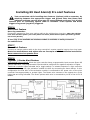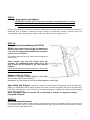
1
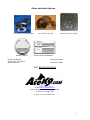
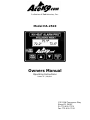
Model HA-2510
Patent # 7,081,811
K9 Heat Alarm® Pro
Installation Manual
Radiotronics Inc.
1315 SW Commerce Way
Stuart Fl 34997
Phone:(772) 600-7574
Fax: (772)600-7012
www.acek9.com
Introduction
K9 Heat Alarm® Pro includes our vehicle monitoring system and Alert Options: S.O.S. Sound Horn
Activation, Dual Window Drop, Emergency Light Activation, and Siren Activation.
HP-2510B Standard Parts
1
1
1
1
1
- Intelabox
- Control Head Cable
– Owners & Install
- Vehicle Specific Instructions*
– Installation Hardware Kit
K9 Heat Alarm
2 - Temperature Sensor
1 - Options Cable
1 - Light Activation Module
1 - Window Drop Module
Standard Outputs
Standard Heat Alarm Outputs
1 – Horn Activation
1 – Siren Activation
1 – Light Activation
1 - Window Drop Activation
Contents
Warnings and Safety information
STEP 1 Overview
STEP 2 Control Head installation
STEP 3 Intelabox installation
STEP 4 Main Power
STEP 5 Connect options cable
STEP 6 Horn Alert Feature
STEP 7 Siren Alert Feature
STEP 8 Lightbar / Strobe Alert
STEP 9 Window Drop Feature
STEP 10 Temperature Sensors
STEP 11 Heat Alarm ignition power
STEP 12 Stall Sensor option
Step 13 Optional add on modules
Step 21 Finish Install and Test System
Trouble Shooting
Optional Outputs for Accessories
(Purchased separately)
1 - Stall Sensor
1 – No K9 Left Behind
1 – Pager Activation
1 – Fan Activation
1 – Auto Starter Activation
For Aftermarket Auto Starters
Accessory Connector
1 – 3 Pin “Daisy Chain Connector”
For additional Accessories
Page
Page
Page
Page
Page
Page
Page
Page
Page
Page
Page
Page
Page
Page
Page
Page
3
4
4
4
4
4
5
5
5
5
6
6
6
7
7
8
2
Safety Warnings and Installation Information
Read these instructions and the vehicle supplement.
It is the responsibility of the Installer to Read these instructions, warnings, and confirm
that all safety features are installed, tested and working properly at the time of
installation.
Refer to the vehicles service manual and modifiers guides during installation.
Do not install equipment in areas that interfere with vehicles safety systems.
Use Caution to avoid damage to wiring, fuel lines, or other equipment.
Never run wires through a drilled hole without a grommet, the wire can become chaffed cause
malfunctions or vehicle fire.
Connectors exposed to moisture should be protected.
As the installer of emergency equipment, proper installation techniques are your responsibility!
______________________________________________________________________________
Important
Install Electronics in dry locations items such as intelabox, control head, relays, and
optional modules.
NEVER install in the following locations
Locations frequently subject to wet conditions
Floor boards
Inside doors
Under K9 transporter
Engine compartment
Against the Air conditioner housing/vents
Under seats
Under cup holders of equipment consoles.
Under the floor mats; this area is subject to excessive heat and moisture and may cause the
unit to malfunction as well as shorten the life of electronic components. Do not install
window module/relays inside of vapor barrier in door.
______________________________________________________________________________
Ignition and Power Warnings
Careful Consideration should be made when connecting devices that could remove power
to vehicle systems, alert features of this product or emergency warning systems that it
activates.
Alarms, Auto Starters, Antitheft Devices or any systems that shut off ignition
power, The K9 Heat Alarm power MUST be set up as “on all the time” (or “auto on
only”) manually shutting down when not in use.
Do not remove factory gender specific quick disconnects. These connectors are designed
for serviceability, prevent accidental damage, and allow for future upgrades.
3
STEP 1
Overview
Review the K9 Heat Alarm® Pro Installation Diagram and vehicle specific install supplement to get
an overview of the hardware placement, wiring and connections. Also review the Installation
Diagram for each of the Heat Alarm Alert Options that you are installing. Make connections
following the order outlined bellow. Consider where connections will be made in the vehicle and run
wires in groups to areas that components are located. Prior planning will speed installation.
STEP 2
Control Head installation
Determine with the K9 Handler a suitable location for the Control Head to be mounted. The Head
should be easily visible to the K9 handler. Mount securely in a dry location inside the vehicle. Choose a
location approved by the vehicle manufacture, see modifiers guide. Plug the control head cable into the
head. “TIP” The mounting bracket can be rotated. To change bracket direction remove the four nuts and
lock washers rotate bracket to desired direction, reinstall hardware.
STEP 3
Intelabox installation
Find a Good location for the Intelabox choose a DRY location where it is easily accessed for future
upgrades; Route the Control Head Cable to the Intelabox. Attach the cable, be sure that the cables
(RJ45) connectors go in straight and the cable is not kinked. Attach the Intelabox Black Ground
wire to a good ground.
When mounting behind trim panels, situate the box temporarily in a location that allows you to easily connect
your wires. Remember control head cable and stall sensor cables are 14’ long efficient routing of these cables
should allow connection in many locations.
STEP 4
Main Power
Connect the Battery wire to an uninterrupted Battery connection point. (Red wire from intelabox)
STEP 5
Connect options cable
Connect the options cable to the 12 pin connector of the intelabox, the connector is keyed to plug
in only one direction. Review the following steps and run the individual wires to their respective
accessories and options.
12 pin connector information
Pin
Color
1
2
3
4
4
5
6
7
8
8
9
10
11
12
Not Used
Not Used
Red
Yellow
Yellow
Not Used
Blue
White (option)
Black/Green
Black/Green
Green
Orange
Orange
Orange
A three pin “daisy
Option / Feature
Function
Polarity
Ignition Power
Autostart
No K9 Left Behind
Power
Optional
No K9 Left Behind
Positive
Negative
Negative
Timed
Door Sense
Module Required
Module Required
Latched
SOS pulse
SOS pulse
SOS pulse
provided for add on
Negative
Window feature
No K9 Left Behind
Fan option
Pager option
Light feature
Horn feature
Siren feature
Spare
chain connector is also
Negative
Negative
Negative
Negative
Negative
Negative
options.
4
Installing K9 Heat Alarm® Pro alert features
Test current draw while installing alert features (Options) with an ammeter, by
attaching between the appropriate trigger and ground. Note that blown fuse
indicates problems; current draw may not exceed 300mA continues. Test all alert
features prior to connecting options cable to intelabox. These Options and Alerts
triggers are ground (negative) triggered.
STEP 6
Horn Alert Feature
Horn ring connection
Connect an orange wire from your options cable to the vehicles horn ring wire. TEST: The vehicles
horn wire will show power (12+ volts) when not active, when the horn pad is pressed it grounds
this circuit (0 volts).
----------------------------------------------------------------------------------------------------------------------
If horn ring is not available an interface module is available to safely connect to
the vehicles horn.
STEP 7
Siren Alert Feature
Connect an orange options cable to the siren controller’s remote negative input or horn ring input.
Most siren manufactures web sights offer on line copies of their installation instructions.
Never connect to siren speaker wire.
STEP 8
Lightbar / Strobe Alert Feature
Programmed input method. When the light controller has a programmable input connect Green K9
options cable wire. The programmable input should be configured for negative activation of lights.
Traditional methods Lights activated buy a toggle switch* or isolated outputs of a light controller
are connected using the light activation module H-LAM-R by connecting as shown bellow. In this
configuration the Red Wire of the activation module is connected to the power wire of the siren
controller fuse appropriately to protect lights. The Brown wire connects to the output wire of the
lights that are being activated. The Green options cable wire is connected to pin 85 of the H-LFX-R
Module.
5
STEP 9
Window Drop Feature (HA-WDM-I)
NEVER Place module in Wet Location Do not place in locations subject to wetness
including floor boards, inside of vapor barrier in door, under K9 transporter, in the
engine compartment, under seats and in center consoles under cup holders.
Refer to Vehicle specific instructions and/or Instructions included with your window drop module. If
Additional wire is added it should be large enough to handle the current. Connect using the
intermediate cable. Window drop options cable provides the Blue triggering wire.
STEP 10
Temperature Sensors Mounting (H-TS22-K)
Never
place sensors where the K9 can damage the
Sensors, behind trim, in direct sunlight, directly in front
of air vent, near equipment that radiates heat, or within 8
inches of floor or headliner.
The sensors should be set up to monitor the area where the
K9 is housed.
Sensor location may vary with vehicle setup and
operation, The Temperature Sensor cables are 15 feet
long so they can be adjusted to the most effective
locations.
Following examples are based the K9 being in a vehicle with
K9 transporter behind the front seats.
Sedans or Pick Up Trucks.
Mount one Temperature Sensor midway up each pillar
trim (on each side) in front of the K9
transporter, or in the airflow at front of the K9 transporter on each side.
Sport Utility and Wagons. Instruction is based on vehicles with K9 transporter behind the front seats.
Mount one temperature sensor midway up pillar trim in front of the K9 Transporter and one on the pillar trim in
back of the K9 Transporter, in good air flow. If area behind transporter is isolated from airflow the Sedan method
may be more appropriate.
Note: Averaging must be turned off if motioning 2 canines in separate climate
controlled locations.
STEP 11
Heat Alarm ignition power
From the Pro Series Option cable connect the Red Ignition wire to switched Ignition Power point on
the Vehicle’s fuse panel or the police package ignition wire. Ignition must be connected for proper
operation of K9 Heat Alarm® Pro
6
STEP 12
Stall Sensor Option (sold separately)
The Stall sensor makes it easy to detect an Engine Stall. The Sensor detects the energy emanating
from the Alternator to determine that the Engine is running. Mount the Stall sensor against the
metal alternator housing, over its internal coils Route the Stall sensor wire through the Firewall to
the Intelabox. If you have to drill a hole, use the supplied grommet, seal with silicone (not
supplied).Cover the stall sensor cable with wire loom, Avoid contact with moving parts and hot
exhaust parts.
VERIFY that the stall sensor functions well after the vehicles battery is fully charged and
under minimal load. The LED on the Sensor is lighted red when the vehicle is stalled or
not running.
“Tip” If the light is red when the vehicle is running it may need to be repositioned
Step 13
Optional add on modules
Connect any add on accessories purchased with system. See instructions included with accessory.
Do not attempt to connect items not approved for use with this system. Use only Acek9.com
accessories.
Additional input/outputs are provided for AceK9 Options. See the Installation Manual provided with
each Option for details about installing that Option.
Step 14 Test System and Finish Install
Test Procedure
System Test Procedure for K9 Heat Alarm® Pro HA-2510
14-A Power. The Default Power Settings is Heat Alarm ON with Ignition. When
Ignition is turned ON, the Heat Alarm unit should power up.
14-B System Status. Observe the Feature Settings during power up. Then observe
the Temperatures and Vehicle’s Battery Voltage. Confirm that the Displayed
Temperatures are below the Heat Alarm Hot Set Point and the System in not in
Snooze Mode.
* STALL SENSOR Note: Due to the popularity of the Engine stall sensor
factory default is enabled, if a stall sensor was not purchased the feature needs to be
disabled in the menu.
14-C System Output Test. Press the MENU key (for a second) to review or change
the Feature Settings or Power Settings. Use the arrow keys to scroll menu. The last
Menu choice is System Test, Press OK to activate all the installed Heat Alarm Alert
options. Verify that ALL the installed Heat Alarm Alert Options worked.
14-D Test Temperature Sensors By Turning the Vehicle’s Climate Control to the
Heat position to manually raise the temperature inside the vehicle. Monitor the
temperatures displayed on the heat alarm and confirm that the alarm activates when
the Hot Set Point is reached. Return the Vehicles Climate Control to the Cool
position.
14-E Engine Stall Sensor Option Test
Turn the Ignition to the ON position WITHOUT Starting the Engine
Note that after the system completes the startup messages it beeps and displays the
Engine Stall Alarm and alarm activates.
14-F Test Heat Alarm Pro add on Accessories.
Refer to the Owner’s Manual(s) for the Operation and Testing
7
If any tests fail please check the installation.
Recheck wiring placement, and connections. Secure cables and wires with cable ties. Install the
intelabox in its appropriate location. Protect all connections, components that may be exposed to
weather, Seal grommets. Completely test of the K9 Heat Alarm® Pro.
IMPORTANT: It is the responsibility of the Installer and the Handler to confirm that all safety
features are installed and working properly at the time of installation. The handler is also
responsible to make continuing periodic checks of all safety systems of this product.
Be sure K9 handler receives a copy of the Owners Manual.
The Owners manuals can be downloaded from www.AceK9.com\manual
____________________________________________________________________________________
Trouble Shooting
Communications Error
Check Control head cable for damage
Check that connectors are fully inserted
Check for corrosion or foreign material.
Check that cable is not running parallel to transmitting
antennas
Heat Alarm Displays Snooze
Alarm is in snooze mode. Start up snooze mode allows the K9 Handler time
to start the vehicle, allow the temperature in the vehicle to reach a safe
level, and resolve any alarm conditions. When the vehicle is running and
the temperature is at a safe level the status light will turn on indicating
monitoring of temperature. (see owners manual)
Stall Sensor Alarm while driving or idling.
Stall sensors adjustment is needed, check location of sensor it needs to be
located over coils in the alternator (see install manual)
Temperature Sensors Show Different Readings
Sensors reading will vary with location and conditions. If it is necessary to
prove the accuracy of the sensors by placing in exact same location, they
will be within less than one degree of another.
Sensor reading differences are caused by the following. (See install manual
for placement)
Sun heating the car body
Air conditioning flow
Open windows or air leaks
Placement of sensors
For additional assistance contact
Acek9.com [email protected] 561-746-0935 x2
Acek9.com Two (2) Year Limited Warranty
For details visit http://www.acek9.com/Warranty
8
Other Available Options
K-9 Cellular Communicator
Smoke Detector
No K9 Left Behind
Heavy Duty Fan Guard
Smoke Detector
10” and 12” Fan Kits
Heavy duty Fan Guard
Carbon Monoxide Detector
Auto Start Option
Anti-theft System
Visit Acek9.com/store
(772) 6 0 0 -7574
E-Mail [email protected]
Hours of operation Monday thru Friday
8:00am to 4:30pm EST
All rights reserved. Radiotronics Inc.
9
A division of Radiotronics, Inc.
Model HA-2510
Owners Manual
Operating Instructions
Patent # 7,081,811
1315 SW Commerce Way
Stuart FL 34997
Ph 772-600-7574
Fax 772-600-7012
Introduction
The K9 Heat Alarm® Pro is a state of the art product designed and
developed by the AceK9.com division of Radiotronics, Inc. It is a unique
blend of positive features taken from actual field use of our K9 Heat
Alarm® plus the incorporation of a microprocessor control system.
Monitoring features: The K9 Heat Alarm® Pro monitors the vehicle’s
interior Temperature and Battery Voltage. The Handler will be alerted by
honking the Horn, rolling down both rear Windows*, activating Emergency
Lights, and Siren. Additional options are Available
Temperature Sensor Averaging – to reduce false alarms.
Exclusive S.O.S Horn Honk .
Non-Volatile Memory – Temperature and other settings are maintained
in memory when power is disconnected.
Dual Window Drop. *Rear windows do not drop in cold alarm
Menu allows you to adjust settings to your needs.
Temperature Sensors Monitor – Warns of damaged sensor and sets off
Alarm if both Temperature Sensors are damaged.
Optional Monitoring features:
o E.S.M. Engine Stall Monitor
– Alerts of Engine Stall BEFORE the
vehicle’s interior gets too hot or cold.
o No K9 Left Behind - K9 removal reminder system
o Smoke Detector
o Carbon monoxide detector
Overview
Factory Default settings are based on the most commonly requested
settings selected by k9 handlers. You can customize them to your
needs. See menu choices section.
Power:
On/Off with vehicle.
Hot Set Point:
90°
Cold Set Point:
Disabled
Engine Stall Monitor: Enabled (Disable if not purchased).
Auto Snooze Mode:
Enabled
USA or Metric
Fahrenheit
Temperature Averaging
Enabled
Dual Temperature Sensor Averaging : The individual Temperature
Sensor readings are displayed along with the average temperature. This
enables the K9 Heat Alarm® Pro to obtain more accurate reading of the
interior temperature of the vehicle. With averaging enabled, unnecessary
false alarms are avoided in marginal temperature conditions or when one
of the Temperature Sensors is in a
warmer/cooler location. (Example: direct
sunlight or open window). In order to
activate the alarm, the AVERAGED (center)
Temperature Sensor readings must reach the
alarm threshold setting (90° Hot Default). As
an additional safety measure the heat alarm
is activated if either Temperature Sensors
reading goes 10 degrees above the threshold
setting.
Disable Temperature averaging if monitoring
two separated locations. To change see the
Menu choices section.
Operation
IMPORTANT safety reminder: It is the responsibility of the Installer and
the Handler to confirm that all safety features are installed and working
properly at the time of installation.
Heat Alarm Power: The Heat alarm will turn on with the ignition. When
the ignition is powered off the heat alarm will power down. This requires
you to leave the vehicle running with the air conditioner ON to maintain a
safe environment for the canine, and remove the K9 if the vehicle is off.
If your environment allows for the canine to be left in the vehicle with the
ignition off, The setting should be changed to ON/Off manually, On with
Car and OFF manually, or No K9 Left Behind (optional hardware required).
Standard Operation: The Left, average, and right Temperatures are
displayed in the primary screen; the Vehicle’s Battery Voltage is displayed
periodically. When the K9 Heat Alarm ® Pro has detected safe conditions
the HOT status light will illuminate, indicating that temperature is being
monitored.
Snooze Mode: At start up, Snooze Mode will
automatically appear if there is an over
temperature or another condition that
requires attention. A Snooze period of
approximately 10 minutes allows time to
get the vehicle running and cooled down for the safety of your K9. When
the K9 Heat Alarm ® Pro does not detect a safe condition at the end of the
snooze period the Pre Alert alarm will activate. Snooze can be manually
reactivated (By pressing OK). Only 3 snooze periods are allowed.
Note: During Snooze, the Handler is responsible to monitor the conditions of
the canine.
Alarm Modes
Pre-Alert Mode. During Pre-Alert a description of the unsafe condition will
Display, along with flashing light and warning tone for 40 seconds. This
allows the K9 Handler to put the unit into Snooze Mode or turn Off the K9
Heat Alarm® Feature before the Full Alarm is activated.
“FULL ALARM” Mode During full alarm all installed Alert Features are
activated. The K9 Heat Alarm ® Pro will continue the Full Alert Alarm Mode
until the temperature or other condition in the vehicle returns to a safe
condition or until the [MENU] key is pressed. If a safe condition is detected
by the system; the Full Alert Alarm Stops and the Display shows a
Reminder Note to advise the K9 Handler that an alarm has occurred.
Clearing reminder: To clear the Alarm Reminder, Press [OK] while the
Note is being displayed.
Temperature Alarm: When a temperature that is above the (averaged)
Hot Set Point or below the Cold Set Point is sensed K9 Heat Alarm ® Pro
goes into Pre Alert. If it remains hot the unit will go into full alarm.
Engine Stall Monitor Option (Purchased separately): With the stall
sensor option installed and enabled in software, the Hot-N-Pop® Pro will
monitor the engine. When the engine stalls “Engine Stalled/Pre-Alert
Mode” is displayed allowing the K9 Handler to Restart the Engine or
Snooze. If no action is taken the Full Alarm is activated.
Vehicle Battery Sentinel : The vehicle’s Battery is monitored and the
Voltage is displayed. If Battery Voltage stays below 11.5 Volts a warning is
displayed and the unit enters Low Voltage mode. The Full Alarm is
activated for a short period of time lowering rear Windows providing
ventilation for the K9. The Alarm will activate again every few minutes as
long as there is enough battery power.
Temperature Sensors Diagnostics: The Temperature Sensors are
continuously monitored; if one of the Sensors is damaged or a connection
is lost, the K9 Heat Alarm Pro will automatically disable Averaging and
operate off of the working sensor. Periodically a warning message and
beep will occur to notify the handler. If both Temperature Sensors are
damaged, the warning message is Displayed, Pre alert starts, followed by
Full Alarm activating.
Self Diagnostics: The K9 Heat Alarm Pro continuously monitors its
internal systems. If a detectable problem exists that would prevent the
system from operating properly the system will go into Full Alarm mode.
_____________________________________________________________________________________________________
*** It is important to remember that, while every effort to monitor
the system is taken, there is no substitute for doing the Weekly
tests outlined in this manual. ***
Changing Settings
Light Intensity adjustment.
The light intensity is controlled by using the [Up] & [Down] arrow keys. The
lights automatically dim, when the vehicle’s ignition is turned OFF (press
the OK key to return it to the original intensity).
Menu Mode: To enter menu mode, power up the K9 Heat Alarm® Pro,
then press the [MENU/POWER] key. To view Menu items Press the [Down]
key for the next item or the [Up] key for the previous item. To change a
Menu item press the [OK] key. The [Up] and [Down] keys let you scroll
through the available settings. To choose a setting, press the [OK] key.
To exit without making changes press the [MENU] key. Additional
changes can be made or press the [MENU] key to exit the Menu Mode.
When returning from the Menu Mode, you will see a review of all the
settings.
Menu Choices
Heat Alarm Power
Default setting is “On/Off with Car” This will turn the Heat Alarm ON &
OFF with vehicles ignition, most commonly the Engine and A/C are usually
left ON to maintain the vehicle’s interior temperature. Remove the K9 if
the vehicle is off.
Alternative Setting “Car on Manual off” The Heat Alarm will turn ON with
ignition and OFF by Keypad. This is the safest method. The unit will
automatically turn ON with the vehicle but will only turn OFF when you
depress and hold the menu key.
Alternative Setting “On/Off Manually” The Heat Alarm will only turn ON
or OFF with Keypad.
Alternative Setting “Off all the Time” The Heat Alarm feature is disabled
requires re-enabling through the Heat Alarm Power Menu.
Alternative Setting “No K9 left behind” the Heat alarm will turn on with
ignition and off when ignition power is off and the Door is opened to
remove the K9. See user supplement sent with this option
(Sold separately)
“Heat Alarm Temp” Hot Set Point
Default setting is 90° to activate the Heat Alarm but can be adjusted from
77° to 95° as your needs require.
“Cold Alarm Temp” Cold Set Point
Default setting “disabled”. The cold Alarm but can be set as your needs
require.
Menu Choices Continued
Stall Monitor Default setting is “Enabled”. When an optional stall sensor is
not purchased this feature should be disabled.
Alternative Setting: Disabled
Temperature Averaging Default setting is “Enabled” so the Temperatures
of the Dual Temperature Sensors are AVERAGED thus reducing false
alarms.
Alternative Setting: Disabled
Auto Snooze Mode Default setting is “Enabled” so Auto Snooze Mode
temporally disables the Heat Alarm to allow time for the vehicle to cool
down during start up.
Alternative Setting: Disabled
USA or Metric Default setting is “Fahrenheit”
Alternative Setting is “Celsius”
Test & Diagnostic features
Previous Alarms Displays the five previous causes of the Alarms.
Serial Numbers Displays the Serial Numbers of the Control Head and the
IntelaBox.
Reset to Default Resets all features to their respective Factory Default
settings.
System Test Pressing [OK] will begin a System Full Alert Test activating
the window drop, SOS Horn, Lights, Siren and Pager. Other Add on options
such as K9 Cellular Communicator , fan, and Radio Voice Module will also
activate. Followed by a Pixel test, that will fill all the pixels in the display,
both top and bottom. Ending with a Push button test will allow testing of
each of the Menu Keys. If any of these tests fail contact you installer or
acek9.com for further assistance.
K9 Heat Alarm® Pro
Weekly System Test Procedure
K-9 should not be in the vehicle during these Tests.
Turn the system on, Observe the Feature Settings during power up, Check
the Temperatures and Vehicle’s Battery Voltage.
K9 Heat Alarm Output Tests
Confirm that the Displayed Temperatures are below the Heat Alarm Hot Set
Point and the System is not in Snooze Mode. Press the MENU key to enter
menu mode. Move down to the menu choice “System Test”, Press OK to
activate all the installed Heat Alarm Alert options. Verify that ALL the
installed Heat Alarm Alert accessories and options worked.
Temperature Sensors Test
Turn the Vehicle’s Climate Control to the Heat position to manually raise the
temperature inside the vehicle. Monitor the temperatures displayed on the
heat alarm and confirm that the alarm activates when the Hot Set Point is
reached. Visually inspect the wiring and electronic components and
confirm that the location of the Temperature Sensors is just outside the K9
container and not in direct sunlight.
Testing of Add on Options
The following procedures are for items added on to the original K9 Heat Alarm Pro. If
not purchased with the original unit, they may be added on in the future. Visit
www.acek9.com for more information.
Engine Stall Sensor Test
Turn the Ignition to the ON position WITHOUT Starting the Engine. Note
that after the system completes the startup messages it beeps and
displays the “Engine Stall Alarm”. If snooze mode is enabled the “Hot
Status” light will turn off for 10 minutes. After 10 minutes the alarm will
sound. If snooze mode is deactivated the unit will go into full alarm with
out delay.
Fan Kit: During the weekly Heat Alarm test the fan will turn on during
system and over temperature tests. In addition the fan should turn on
manually from the toggle switch. The fan should always blow in toward the
K9.
For Other Options see instruction manual that was provided
If any tests fail contact you installer or AceK9.com for assistance.
AceK9.Com Two (2) Year Limited Warranty
For details visit http://www.acek9.com
All rights Reserved, Radiotronics Inc