1
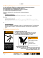
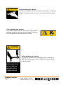
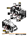
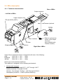
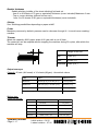
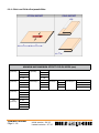
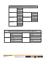
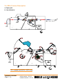
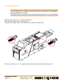
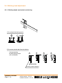
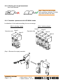
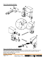
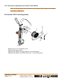
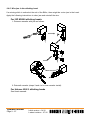
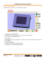
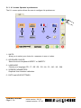
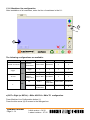
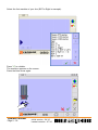
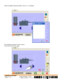
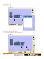
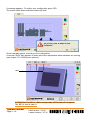
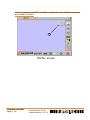
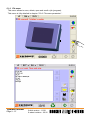
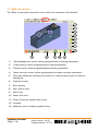
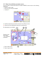
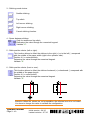
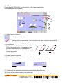
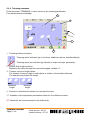
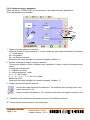
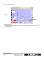
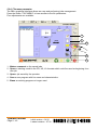
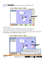
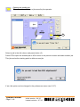
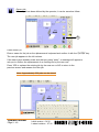
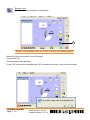
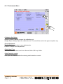
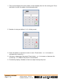
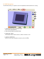
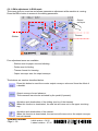
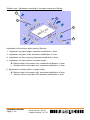
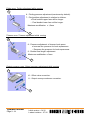
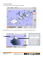
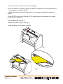
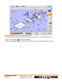
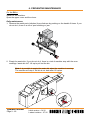
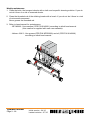
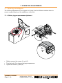
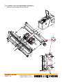
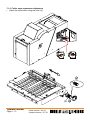
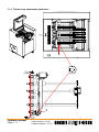
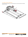
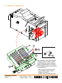
OPERATOR MANUAL Initial version: 11/08 Lastest revision: 07/10 9.134.030 Content of this documentation remains the exclusive property of C.P. Bourg SA and it is only put at the user (including without limitation: Renter or Purchaser or their employees) disposal within the exclusive scope of using and servicing the product. Without C.P. Bourg SA prior agreement in writing, reproductions as well as changes are prohibited. Operator manual Page 9 - 2 Initial version : 04/10 Lastest revision : 07/10 TABLE OF CONTENTS 1. IMPORTANT . . . . . . . . . . . . . . . . . . . . . . . . . . . . . . . . . . . . . . . . . . . . 5 2. INTRODUCTION . . . . . . . . . . . . . . . . . . . . . . . . . . . . . . . . . . . . . . . . . 6 2.1. Foreword . . . . . . . . . . . . . . . . . . . . . . . . . . . . . . . . . . . . . . . . . . . . . . . . . . 6 3. BM-e . . . . . . . . . . . . . . . . . . . . . . . . . . . . . . . . . . . . . . . . . . . . . . . . . . 7 3.1. Warning Pictograms . . . . . . . . . . . . . . . . . . . . . . . . . . . . . . . . . . . . . . . . . . 7 3.2. Warning pictograms location . . . . . . . . . . . . . . . . . . . . . . . . . . . . . . . . . . . . 7 3.3. BM-e description . . . . . . . . . . . . . . . . . . . . . . . . . . . . . . . . . . . . . . . . . . . 12 3.3.1. Technical characteristics ................................................................12 3.3.2. Stitching possibilities depending on paper width . ..........................15 3.3.3. Technical specifications . ................................................................16 3.3.4. Stitch and Fold offset possibilities...................................................18 3.4. BM-e Process Description . . . . . . . . . . . . . . . . . . . . . . . . . . . . . . . . . . . . 20 3.5. BM-e power ON . . . . . . . . . . . . . . . . . . . . . . . . . . . . . . . . . . . . . . . . . . . . 21 3.6. Stitching head adjustment . . . . . . . . . . . . . . . . . . . . . . . . . . . . . . . . . . . . . 22 3.6.1. Stitching heads mechanical unclutching ........................................22 3.6.2. Stitching wire length adjustment . ...................................................23 3.6.3. Cassettes replacement with ISP M2000 heads...............................23 3.6.4. Wire spool replacement (for Hohner 43/6 S heads) . .....................26 3.6.5. Wire jam in the stitching head ........................................................27 4. THE USER INTERFACE (UI) SCREENS . . . . . . . . . . . . . . . . . . . . . 28 5. SCREEN FUNCTIONS IN DETAIL . . . . . . . . . . . . . . . . . . . . . . . . . . 29 5.1. U.I. screen options . . . . . . . . . . . . . . . . . . . . . . . . . . . . . . . . . . . . . . . . . . 29 5.1.1. U.I. screen Operator's preferences ................................................30 5.1.2. Machines line configuration ............................................................31 5.1.3. File menu . .....................................................................................37 5.2. BME tab options . . . . . . . . . . . . . . . . . . . . . . . . . . . . . . . . . . . . . . . . . . . . 38 5.2.1. Paper size and Stitcher parameters screen ...................................39 5.2.2. Folding parameter ..........................................................................41 5.2.3. Trimming parameter .......................................................................42 5.2.4. Output conveyor parameter . ..........................................................43 5.2.5. Summary parameter .......................................................................44 5.2.6. File menu parameter ......................................................................45 5.2.7. Preferences Menu...........................................................................51 5.2.8. Warning screen and error messages .............................................53 5.2.9. STOP buttons .................................................................................54 5.2.10. Start buttons .................................................................................54 5.2.11. Pause button ................................................................................54 5.2.12. Purge button .................................................................................54 5.2.13. Counter of set (configuration BM-e) .............................................55 5.2.14. U.I. version and update history ....................................................57 5.3. RUN tab options . . . . . . . . . . . . . . . . . . . . . . . . . . . . . . . . . . . . . . . . . . . . 58 5.3.1. BM-e adjustment in RUN mode .....................................................59 5.3.2. Manual feeding ...............................................................................62 Operator manual Page 9 - 3 Initial version : 04/10 Lastest revision : 07/10 6. PREVENTIVE MAINTENANCE . . . . . . . . . . . . . . . . . . . . . . . . . . . . . 65 7. OPERATOR ADJUSTMENTS . . . . . . . . . . . . . . . . . . . . . . . . . . . . . . 68 7.1. Squaring and stoppers . . . . . . . . . . . . . . . . . . . . . . . . . . . . . . . . . . . . . . . 68 7.1.1. Stitcher joggers squareness adjustment ........................................68 7.1.2. Stitcher front stop squareness adjustment .....................................69 7.1.3. Folder trays squareness adjustment ..............................................70 7.1.4. Trimmer stop squareness adjustment ............................................71 7.2. Output conveyor adjustment . . . . . . . . . . . . . . . . . . . . . . . . . . . . . . . . . . . 72 7.3. Folder ball replacement . . . . . . . . . . . . . . . . . . . . . . . . . . . . . . . . . . . . . . . 73 8. ENVIRONMENTAL COMPLIANCE . . . . . . . . . . . . . . . . . . . . . . . . . 74 8.1. Product recycling and Disposal . . . . . . . . . . . . . . . . . . . . . . . . . . . . . . . . . 74 Operator manual Page 9 - 4 Initial version : 04/10 Lastest revision : 07/10 1. IMPORTANT F: Important Cette machine ne peut fonctionner qu'avec toutes les sécurités au repos (capots plexi) et tous les accessoires (plateau de réception ou de transfert, convoyeur de sortie, conteneur déchets de coupe) en place. Attention: Garder les mains à l’écart des pièces en mouvement. GB/US: Important This machine will operate only with all the safety devices of the collating / finishing line deactived (guards) and delivery/transfer tray or conveyor waste container connected in working position. Caution: Keep hands clear of moving parts. D: Wichtig Diese Maschine kann nur in Betrieb genommen werden, wenn alle Sicherheitsvorrichtungen der Verarbeitungsstrasse (Plexihauben, Notschalter, Empfangs oder Transfertplatte Auslage) sich in Arbeitsposition befinden. Achtung: Hände nicht in die Nähe laufender Maschinenteile bringen. ESP: Importante Esta máquina sólo se pondrá en funcionamiento cuando todos los dispositivos de seguridad de la línea de clasificación / acabado estén desactivados (dispositivos protectores) y la bandeja de salida / transferencia o el contenedor de desechos de la transportadora estén conectados en la posición de funcionamiento. Precaución: Mantenga las manos alejadas de las partes móviles. Operator manual Page 9 - 5 Initial version : 04/10 Lastest revision : 07/10 2. INTRODUCTION 2.1. Foreword Thank you for choosing a BOURG product. This manual is a guide to operate the Booklet Maker E series. Please follow carefully the instructions and you will enjoy years of excellent work with your system. If you have any difficulty using your equipment, please call us and ask for technical assistance (all the phone numbers are available at the end of this manual). We will be delighted to help you. All the information in this publication is based on the latest information available at the time of approval for printing. We reserve the right to revise this publication and to make changes in the content without obligation to notify such revision or changes. THIS MANUAL IS INTENDED TO BE USED EXCLUSIVELY BY QUALIFIED TECHNICAL PERSONNEL. Operator manual Page 9 - 6 Initial version : 04/10 Lastest revision : 07/10 3. BM-E 3.1. Warning Pictograms The BM-e is a booklet maker which produces booklets or side stitched documents. All format settings will be done automatically from the U.I. The booklet maker jogs the set and in this position it is stitched. The booklet is then folded and is front trimmed. Please pay attention to the description of the following pictograms: Caution: on a yellow background, indicates a hazardous situation that can cause small or severe injury. Warning: on a orange background, indicates a hazardous situation which has some probability of death or severe injury. Warning should not be considered for property damage accidents unless personal injury risk is present. Danger: on a red background, indicates a hazardous situation with a high risk of death or severe injury. The ‘danger’ sign does not apply to accidents causing material damage, unless they can cause personal injury. 3.2. Warning pictograms location range background, warning. O This label is located near the main power unit. It warns of a high risk of electrocution when opening the power supply box with a risk of severe injury or death. WARNING KEEP HANDS CLEAR CAN CAUSE SEVERE INJURY Orange background, warning. This label is located near the knife of the folding machine. It warns of a high risk of severe hand injuries when placing your hands under the knife. Operator manual Page 9 - 7 Initial version : 04/10 Lastest revision : 07/10 CAUTION Yellow background, caution. This label is located near the knife of the press-cutter. It indicates a high risk of severe injury if you put you hands under the knife. Yellow background, caution. This label is located near the wheel-work of the chain. It indicates a high risk of injury to your fingers if they get stuck between the wheel-work and the chain. CAUTION Yellow background, caution. This label is located near the stapling head. It indicates a high risk of severe injury to your fingers if you place them under this head. KEEP HANDS CLEAR DO NOT OPERATE WITHOUT SAFETY COVERS IN PLACE Operator manual Page 9 - 8 Initial version : 04/10 Lastest revision : 07/10 CAUTION Yellow background, caution. This label is located at the rear of the machine under the safety cover. It indicates that the machine may not be operated, under no circumstances, without the safety covers being in place. DO NOT OPERATE WITHOUT SAFETY COVERS IN PLACE Yellow background, caution. This label is located near the main power supply. It indicates that this power supply cabinet may only be opened by qualified personnel. CAUTION ELECTRICAL HAZARD AUTHORIZED SERVICE PERSONNEL ONLY CAUTION PINCH POINTS KEEP HANDS CLEAR Operator manual Page 9 - 9 Initial version : 04/10 Lastest revision : 07/10 Yellow background, caution. This label is located near the primary shaft. It indicates a high risk of severe injury to your fingers if they get stuck in the belt CAUTION LISTED I.T.E. E125337 MODEL : AGR-PA BME VOLTS : 120 : A 8 : Hz 60 AGR-PA BME 230 5 50 Refer to Installation Manual for motor connection c.p. bourg MADE IN BELGIUM BY S.A. Ottignies Tel : +32 / 10 / 62 22 11 Fax : +32 / 10 / 61 36 38 9.139.829 KEEP HANDS CLEAR DO NOT OPERATE WITHOUT SAFETY COVERS IN PLACE WARNING CAUTION HAZARDOUS VOLTAGE CAN CAUSE SEVERE INJURY OR DEATH PINCH POINTS KEEP HANDS CLEAR WARNING KEEP HANDS CLEAR CAN CAUSE SEVERE INJURY CAUTION ELECTRICAL HAZARD AUTHORIZED SERVICE PERSONNEL ONLY Operator manual Page 9 - 10 Initial version : 04/10 Lastest revision : 07/10 Initial version : 04/10 Lastest revision : 07/10 TR BME 230 3 50 c.p. bourg Refer to Installation Manual for motor connection AC TY PL E FE ER AT CAUTION ION UT CA DO E KEEP HANDS CLEAR PINCH POINTS CAUTION LISTED I.T.E. E125337 TR BME 120 5 60 MADE IN BELGIUM BY S.A. Ottignies Tel : +32 / 10 / 62 22 11 Fax : +32 / 10 / 61 36 38 MODEL : VOLTS : : A : Hz NO T OP OU ITH W SA RS IN T VE Page 9 - 11 CO Operator manual 9.139.830 CAUTION COVERS IN PLACE WITHOUT SAFETY DO NOT OPERATE CAUTION PERSONNEL ONLY AUTHORIZED SERVICE ELECTRICAL HAZARD 3.3. BM-e description 3.3.1. Technical characteristics Rear of BM-e Output conveyor Left Side of BM-e Upper reception tray ITE with BSTd+/BST-e Trimmer (optional 50 Hz 60 Hz User interface Folder 50 Hz Stitcher Front of BM-e Right Side of BM-e 60 Hz Verify that you electrical service USA 120V AC +/- 10% EUROPE 230V AC +/- 10% JAPAN 230V AC +/- 10% corresponds with one of the following: - 60Hz - 50Hz - 60Hz Check your environmental conditions. This machine is designed for the following environment: • Storage and transport: Temperature: -34°C through 60°C / -30°F through 140°F Relative humidity: 5 through 90% RH Altitude: -31m through 12,192m / -100 ft.through 40,000 ft. Atmospheric pressure: ≥ 56kPa (420mm Mercury) Operator manual Page 9 - 12 Pedal to activate the motion of the output conveyor. (only available with Trimmer module) Initial version : 04/10 Lastest revision : 07/10 • Work environment: Temperature: 10°C (50°F) through 32°C (89.6°F) Relative humidity: 40 through 85% RH • Power consumption: Consumption Machines Maximum 230 V 50Hz 120 V 60Hz In operation 230 V 50Hz 120 V 60Hz Stitcher/Folder 994 W 924 W 740 W 760 W Stitcher/Folder/Trimmer 1675 W 1480 W 1110 W 1160 W • BTU output: from 2525 to 5700 BTU/H (complete system). • Noise level: 70 dB. Warning: Never remove the power cord while the machine is turned ON. General -Input/Output paper path: 860 mm without ITE and 610mm with ITE. -Variable speed of input motor. -Centered registration: the BM-e positions itself to the center of the processed paper format from the upstream registered equipment thanks to a transversal motorization. -Full automatic adjustment depending on the format. -Upper reception tray for top/edge/corner stitched booklet or poor booklet. - Paper path jam, open baffles and open covers detectors. - Detection of output conveyor full and trim waste bin full. - Machine is managed via the U.I. - Different component position (heads/stops/joggers/Folder press/Trimmer press/holding wheels/output conveyor motion) is automatic depending on the defined job in the U.I. - Fine adjustments are possible while machine is working. Stitcher -The BM-e is equipped with 2 or 4 stitching heads. -Equipped with ISP M2000 stitching heads featuring toolless change over self threading cassette for stitch wire supply. -On demand before delivery, the machine can be equipped with 2 or 4 Hohner 43/6 S heads compatible with various diameter wire. -Hohner 43/6 S heads convertible to loop stitch model via optional upgrade kit. -Heads supplied with wire n°25 (EU) or 25 Gauge (US). -Capacity of 40.000 stitches (75 gsm, 2 to 30 sheets). Folder -Booklets folded between the belts with a fold crush device. -Book press integrated in the folder. - Booklet pressure can be adjusted via the U.I. Trimmer -Upper and lower knives, without heel, can be easily replaced. -Equipped with a system to ease the ejection of the chips. -Waste bin that can be emptied while machine is working. Operator manual Page 9 - 13 Initial version : 04/10 Lastest revision : 07/10 Output conveyor - Operator adjustment on U.I. output conveyor advance step per book. - Output conveyor full detector (can be disabled). - Device to offset the sets - offset every N sets, with N adjustable by operator on U.I. - Automatic positioning of set holding wheels, based on finished set dimensions. - Pedal to activate the motion of the output conveyor (only available with Trimmer module). Operator manual Page 9 - 14 Initial version : 04/10 Lastest revision : 07/10 3.3.2. Stitching possibilities depending on paper width Paper width Stitch Machine Type position 2 saddle or 2 heads on 2 top bracket heads 1 corner 119 mm (4.7") to 218 mm (8.6 ") 218.1 mm (8.6") to 268 mm (10.5") 268.1 mm (10.5") to 370 mm (14.6") Space between stitches = 80 mm (3.1") to paper width - 28 mm (1.1") YES (left or right) "Space between stitches = "Space between "Space between 80 mm (3.1") to 190 mm stitches = stitches = 2 saddle or (7.5") (middle 80 mm (3.1") to paper 80 mm (3.1") to top brackets**) and 2 heads on 4 width - 28 mm (1.1") 190 mm (7.5") 240 mm (9.4") to paper bracket heads* (middle brackets**)" (middle brackets**)" width - 28 mm (1.1") (outside brackets**)" YES (left or right YES (left or right outside 1 corner Not possible middle brackets**) brackets**) "Space between stitches "Space between "Space between = stitches = stitches = 80 mm (3.1") to 190 mm 2 saddle or 80 mm (3.1") to paper 80 mm (3.1") to (7.5") (middle heads) and top width - 28mm (1.1") 190 mm (7.5") 240 mm (9.4") to paper (middle heads)" (middle heads)" width - 28 mm (1.1") (outside heads)" 4 heads "Space between middle 4 saddle or stitches = Not possible top 80 mm (3.1") to paper width - 188 mm (7.4") YES (left or right YES (left or right outside 1 corner Not possible middle head) heads **) * Requires installation of heads on proper brackets (middle or outside ones) ** Stitching head position at installation On demand before delivery, the machine can be equipped with 4 heads brackets but only 2 heads. In this case it could be upgraded with 2 additional heads. Corner stitching The middle of the stitch is placed at 14mm from the side (left or right) of the sheet and at 7mm from the lead edge of the sheet. You must clutch and activate the used head(s). 14mm 0.5" 7mm 0.27" 14mm 0.5" 7mm 0.27" To avoid severe mechanical interferences which could lead to serious damages, unclutch the unused heads when it is asked on User Interface. Operator manual Page 9 - 15 Initial version : 04/10 Lastest revision : 07/10 3.3.3. Technical specifications Note:The figures below represent what the BM-e is capable of producing. The device feeding paper to the BM-e may alter those specifications. Type of paper Any type of paper except paper with a window or transparent paper. Coated / uncoated from 60 to 160 gsm. Covers from 80 to 250 gsm (up to 350 gsm if the covers are creased). Paper size Top/side stitching Saddle stitching Min = 119mm (4.7") Max = 370mm (14.6") Min = 119mm (4.7") Max = 370mm (14.6") Min = 180mm (7.1") Max = 600mm (23.6") Min = 170mm (6.7") Max = 300mm (11.8") Folding/Trimming Max. trim = 25mm (1") For a format higher than or equal to 190mm (95mm folded) Min = 119mm (4.7") Max = 370mm (14.6") Min = 70mm (2.8") Max = 300mm (11.8") Productivity PRODUCTIVITY (books / h) (over lap 15 mm) A4 A3 8,5 / 11 11 / 17 5 sheets 5050 4350 5150 4300 10 sheets 4700 4100 4850 4050 15 sheets 4450 3900 4600 3900 EURO USA Note: The specified paper thickness figures are given for guidance only. The actual performances of the machine will depend on the nature of the paper and covers used. Operator manual Page 9 - 16 Initial version : 04/10 Lastest revision : 07/10 Booklet thickness Saddle stitching (middle of the sheet stitching) fold and cut : - from 2 to 30 sheets of 75 gsm or equivalent thickness (cover included) Maximum 3 mm. -Top or corner stitching (without fold nor cut) : from 2 to 55 sheets of 80 gsm or equivalent thickness (cover included). Stitcher See “Stitching possibilities depending on paper width”. Folder Maximum pressure by default, pressure can be decrease through U.I. to avoid cover marking/ crackles. Trimmer Waste bin capacity: 8000 paper strips of 80 gsm with a cut of 5mm. The waste bin can be emptied without stopping the machine during 50 cycles, after which the machine will stop. Length of the cut Min. 0 mm (0”) Max. 25 mm (1”) Standard 5 mm (0.2”) Output conveyor Capacity: 42 sets (A4 format) of 10 sheets (80gsm) - theoretical values. Step Value Value on U.I. Minimum 20 mm (0.8”) ± 10 mm (0.4”) 1 mm (0.04”) Maximum 330 mm (13”) ± 40 mm (1.6”) 29 mm (1.1”) Default value 8 mm (0.3”) Output conveyor does not stop 30 mm (1.2”) Motion step: Offset set device: Minimum Maximum Operator manual Page 9 - 17 Offset Value on U.I. No offset 1 mm (0.04”) Offset of 2nd set 2 mm (0.08”) Offset of 3rd set 3 mm (0.1”) Offset of nth set 11 mm (0.4”) Offset of 250th set 250 mm (9.8”) Initial version : 04/10 Lastest revision : 07/10 3.3.4. Stitch and Fold offset possibilities MINIMUM AND MAXIMUM OFFSET FOR EU SIZES (mm) A3 (portrait) : A4 (portrait) : A5 (portrait) : A= -90 B= 90 SRA3 (portrait) : A= -75 B= 75 C= -90 C= -75 D= 120 D= 135 A= -58,5 B= 58,5 A4 A= -15 (landscape) : B= 15 SRA4 A= -70 (portrait) : B= 70 C= -151,5 C= -195 C= -140 C=-187,5 D= 58,5 D= 15 D= 70 D= 22,5 A= - 15 B= 15 C= -195 D= 15 CD (portrait) : A= -35 B= 35 C= -175 D= 35 Operator manual Page 9 - 18 SRA4 A= -22,5 (landscape) : B= 22,5 Initial version : 04/10 Lastest revision : 07/10 MINIMUM AND MAXIMUM OFFSET FOR USA SIZES (inch) 17x11 (portrait) : A= -3,31 B= 3,31 C= -3,31 D= 4,96 11x8,5 (portrait) : A= -1,96 B= 1,96 C= -6,31 D= 1,96 A= -1,46 B= 1,46 C= -6,81 D= 1,46 A= -1,38 B= 1,38 C= -6,89 D= 1,38 10x8 (portrait) : CD (portrait) : 8.5x11 (landscape) : 8x10 (landscape) : A= -0,71 B= 0,71 C= -7,56 D= 0,71 A= -0,46 B= 0,46 C= -7,81 D= 0,46 MINIMUM AND MAXIMUM OFFSET FOR JAPANESE SIZES (mm) B4 (portrait) : B5 (portrait) : A= -92 B= 92 C= -118 D= 92 A= -38,5 B= 38,5 C= -171,5 D= 38,5 Operator manual Page 9 - 19 B4 (landscape) : B5 (landscape) : Initial version : 04/10 Lastest revision : 07/10 A= -38,5 B= 38,5 C= -171,5 D= 38,5 A= -1 B= 1 C= -209 D= 1 3.4. BM-e Process Description a. Paper path b. Jam clearance ITE ITE ITE : avalaible with BSTd+ / BST-e only Operator manual Page 9 - 20 Initial version : 04/10 Lastest revision : 07/10 3.5. BM-e power ON In order to prevent any danger during the installation, the usage or the maintenance of the equipment, the connection to the mains must be located near the equipment and be accessible at all times. The BM-e must be connected to the main power protected by a 15 A circuit breaker. Starting order: Trimmer (1) - Stitcher / Folder (2). Push on main switch to set it on position “I”. The green led lights. After a few seconds, the machine initialize itself. r e m m i Tr r r F e tch i St e d l o There is no switch on U.I., it is supplied with electricity by the Stitcher-Folder module. Operator manual Page 9 - 21 Initial version : 04/10 Lastest revision : 07/10 3.6. Stitching head adjustment 3.6.1. Stitching heads mechanical unclutching 1) To unclutch the locking catch: 2) To remove stitcher bar from the Stacker: Same procedure for both kind of heads (ISP & HOHNER) 1 2 Stitcher bar Locking catch (keeper) Operator manual Page 9 - 22 Initial version : 04/10 Lastest revision : 07/10 3 4 3.6.2. Stitching wire length adjustment See Head Manuals. Note : There is a risk of injury while handling a booklet if a stitch leg is shorter than the other. 3.6.3. Cassettes replacement with ISP M2000 heads Localization of the heads according the error message. With 4 stitching heads: With 2 stitching heads: Head 1 Operator side Operator side Head 1 Head 2 Head 3 Head 2 Head 4 Step 1: Remove the empty cassette: 1 4 3 2 Operator manual Page 9 - 23 Initial version : 04/10 Lastest revision : 07/10 Step 2: stitching head prevention cleaning: The stitching head must be lubricated each time the cassette is replaced. Please use the tube of vaseline delivered together with the cassettes. Note: According to MSDS and 2000/532/EC lubricant is not a hazardous substance. The lubricant should be used until the tube is empty. The empty tube should be thrown away to domestic or industrial waste. See Head manuals. Operator manual Page 9 - 24 Initial version : 04/10 Lastest revision : 07/10 Step 3: New cassette installation: 2 1 3 5 7 4 6 Step 4: Re-initialization of the stitching head: When removing the rotator operating spring from the stitching head (for lubrification) you will loose the wire for next stitch. Therefore the stitching head must be actuated to make the machine again available for next booklet. Execute a manual stitching. Operator manual Page 9 - 25 Initial version : 04/10 Lastest revision : 07/10 3.6.4. Wire spool replacement (for Hohner 43/6 S heads) Note: Oil the felt discs on the wire bow of the Hohner 43/6 S heads. See chapter : Preventive maintenance. For Hohner 43/6 S stitching heads. 3 1 hoh ner UNIV ERS 48/5 AL S 2 -Remove pin ref.1 and washer ref.2. -Remove the empty spool. -Install a new spool ref.3 (pay attention to wire direction). -Reinstall the washer ref.2 and the pin ref.1 in the shaft groove. Operator manual Page 9 - 26 Initial version : 04/10 Lastest revision : 07/10 3.6.5. Wire jam in the stitching head If a missing stitch is noticed at the exit of the BM-e, there might be a wire jam in the head. Apply the following instructions to clear jam and reinstall the wire. For ISP M2000 stitching heads 1- Remove cassette with jam as follows. 9mm 1 2 2- Reinstall cassette (steps 3 and 4 of a new cassette install). For Hohner 43/6 S stitching heads See Head manuals. Operator manual Page 9 - 27 Initial version : 04/10 Lastest revision : 07/10 4. THE USER INTERFACE (UI) SCREENS The User Interface is a touch screen. Select your choice by pressing on the screen with your finger. The User Interface is divided into several tabs that vary according to the configuration. Each tab has its own preference and/or adjustment buttons. The control buttons are common to all tabs. Software version / Date Tabs Adjustment buttons Care and cleaning Control buttons Do not place anything on the screen. Do not let liquid get on or into the screen. Use a regular glass cleaner to clean the screen (proceed as explained below). To clean the screen: 1. S witch off the Stitcher/Folder machine. Do not use a spray cleaner on the screen, because the cleaner may drip inside. 2. Wet a soft cotton cloth with the cleaning solution and gently wipe the screen. 3. Do not use cleaning solutions containing solvents. Dry with a clean, soft cotton cloth. CAUTION : Danger of explosion if battery is wrongly replaced. Replace only with the same or equivalent type recommended by the manufacturer. Dispose of used batteries according to the manufacturer's instructions. See Section Adjustment/ Replacement of Service Manual for battery replacement. Operator manual Page 9 - 28 Initial version : 04/10 Lastest revision : 07/10 5. SCREEN FUNCTIONS IN DETAIL 5.1. U.I. screen options At machine power ON, the U.I. screen appears by default. 1 2 3 4 5 1 - OPERATOR'S PARAMETERS: Press button to the right of the screen to enter your own parameters. 2 - MACHINE LINE CONFIGURATION: 3 - FILE MENU: Allows to open/delete an existing job or create/save a new job. Available if the step two has been validated. 4 - TECHNICIAN MENU: Autorised to be used by a qualified technician. 5 - INFORMATION AND ERROR MESSAGES Operator manual Page 9 - 29 Initial version : 04/10 Lastest revision : 07/10 5.1.1. U.I. screen Operator's preferences The U.I. screen option allows the user to configure his preferences. 1 2 3 4 5 1 - UNITS: Allow you to select your choice for measures in mm or inches. 2 - KEYBOARD CHOICE: Select the kind of keyboard AZERTY or QWERTY. 3 - LANGUAGE: Choose your language (FR - IT - DE - ES - PO - NL - PL - NO - US - GB). 4-S CREEN PARAMETERS: Graphical User Interface calibration. 5 - DATE and HOUR SETTINGS. Operator manual Page 9 - 30 Initial version : 04/10 Lastest revision : 07/10 5.1.2. Machines line configuration After installation of all machines, enter the line of machines in the U.I. 1 2 The following configurations are available: Left accessorie Feeder Right Acc #1 See BST-d+ manual BST-d+ Stitcher/ Folder BM-e Criss/cross Jogger Criss/cross Jogger BST-e TD Left TD Right Stitcher/ Folder BM-e IFB - BSF BCM-e Right Acc #2 Right Acc #3 Trimmer BM-e SpineMaster - - Trimmer BM-e SpineMaster BCM-e Right Acc #4 Right Acc #5 - - - - Stitcher/ Trimmer BM-e Folder BM-e Stitcher/ Trimmer BM-e Folder BM-e SpineMaster a) BST-e Right (or BSTd+) + BM-e AGR-PA + BM-e TR configuration. Press Machine Line Configuration button (1). Press the blue arrow (2) to access to the dialogue box. Operator manual Page 9 - 31 Initial version : 04/10 Lastest revision : 07/10 SpineMaster - Select the first machine of your line (BST-e Right in example). Press "V" to validate. The machine appears on the screen. Press the blue arrow again. Operator manual Page 9 - 32 Initial version : 04/10 Lastest revision : 07/10 Select the BM-e Stitcher/Folder. Press "V" to validate. The machine appears on the screen. Press the blue arrow again. Operator manual Page 9 - 33 Initial version : 04/10 Lastest revision : 07/10 Select the BM-e TR. Press "V" to validate. The machine appears on the screen. The configuration is finished, valid by pressing "V". Operator manual Page 9 - 34 Initial version : 04/10 Lastest revision : 07/10 A message appears. To confirm your configuration press YES. The screen shuts down and then restarts by itself. Some new tabs appear according to the configuration. A new tab "RUN" also appears to make some fine adjustments while machines are running (see chapter "5.3. RUN screen options"). Tabs ATTENTION: For BSTd+ / BM-e configuration, BSTd+ tab will not appear. The BSTd+ has its own U.I. Operator manual Page 9 - 35 Initial version : 04/10 Lastest revision : 07/10 Note: To complete the BSTd+ and BM-e configuration. Go to BSTd+ screen and press SBM4 (4) button. 4 BSTd+ screen Operator manual Page 9 - 36 Initial version : 04/10 Lastest revision : 07/10 5.1.3. File menu This menu allows to save, delete, open and recall a job (program). This menu is fully detailed in chapter "5.2.6. File menu parameter" . Operator manual Page 9 - 37 Initial version : 11/08 04/10 Lastest revision : 02/10 07/10 5.2. BME tab options The “BM-e” screen option allows the user to define the realization of the booklet. 1 2 3 4 5 6 7 8 13 12 11 10 9 1) Stitching/paper size screen: allows programming the stitching parameters. 2) Folding screen: allows programming the folding parameters. 3) Trimmer screen: allows programming the trimming parameters. 4) Output conveyor screen: allows programming the output conveyor parameters. 5)File menu: allows the recording, the creation of a new job and to open or erase an existing job. 6) Preference menu. 7) Error warning. 8) Stop: End of cycle. 9) Start of job. 10) Pause: Not used. 11) Purge: Clears the machine after a jam. 12) Counters. 13) Software version: Software update history. Operator manual Page 9 - 38 Initial version : 04/10 Lastest revision : 07/10 5.2.1. Paper size and Stitcher parameters screen Press the button "PAPER SIZE AND STITCHER SCREEN" to have access to the stitching parameters. • Press on value to edit • Enter the value using the keypad. • Validate "V". "V" Valid the adjustment parameters entered in the different screen. "X" Cancel the last modifications entered in the defined job. Six adjustments are available: 4 5 6 3 Summary area See chapter "5.2.5. Summary parameter" 1 2 1 - Paper width choice. 7 2 - Paper length choice. Operator manual Page 9 - 39 Initial version : 04/10 Lastest revision : 07/10 3 - Stitching mode choice. Saddle stitching. Top stitch. Left corner stitching. Right corner stitching. Cancel stitching function. 4 - Space between stitches. Only for saddle and top stitch. Determine the value through the numerical keypad. Validate "V". 5 - Stitch position choice (left or right). This function allows to offset the stitches to the right (+) or to the left (-) compared with the middle of the paper width (right is the operator side). Position 0,0 = centered stitch. Determine the value through the numerical keypad. Validate "V". 6 - Stitch position choice (front or rear). This function allows to offset the stitches frontward (+) or backward (-) compared with the middle of the paper length. Position 0,0 = centred stitch. Determine the value through the numerical keypad. Validate "V". Attention: When the values are not compatibles, the affected area is in red colour. You have to change the value to validate the configuration. Operator manual Page 9 - 40 Initial version : 04/10 Lastest revision : 07/10 5.2.2. Folding parameter Press the button "FOLDING" to have access to the folding parameters. Three adjustments are available: 1 2 3 1- Folding function selection: Folding option activated. Folding function not activated. Sets are sent to the upper reception tray and the 2 other parameters are not available. 2 - Fold position: By default, the fold will always be in the middle (0,0) of the paper length. It is possible to offset the paper fold frontward (+) or backward (-). Press area 2 and determine the value through the numerical keypad. Validate "V". 3 - Folding pressure selection: By default, the pressure will always be maximum. Decrease the pressure if there are too many cracks or marks on the cover. More pressure Less pressure "V" Validation of the adjustment parameters entered in the different screens. "X" Cancel the last values entered in the defined job. Operator manual Page 9 - 41 Initial version : 04/10 Lastest revision : 07/10 5.2.3. Trimming parameter Press the button "TRIMMING" to have access to the trimming parameters. Four adjustments are available: 1 2 4 3 1 - Trimming function selection. Trimming option activated (go to the three additional options described below). Trimming option not activated (go directly to output conveyor parameter). 2 - Booklet final length selection. Determine the value through the numerical keypad, validate "V" . 3 - Trimmer conveyor height choice. The trimmer conveyor height is self adjusts in relation to the booklet thickness. The operator may adjust this height. Maximum height Minimum height 4 - Activate or deactivate the blower to evacuate the chips. "V" Validation of the adjustment parameters entered in the different screens. "X" Cancel the last values entered in the defined job. Operator manual Page 9 - 42 Initial version : 04/10 Lastest revision : 07/10 5.2.4. Output conveyor parameter Press the button "CONVEYOR" to have access to the output conveyor parameters. Three adjustments are available : 1 2 3 1 - Output conveyor advances selection. Adjust the output conveyor advance (1 to 30) to obtain the space desired between the booklets. 1 = small space 29 = long space 30 = continuous advance Determine the value through the numerical keypad, validate "V". 2 - Booklet offsetting on output conveyor selection. This function allows to offset a booklet every x booklets in order to count the booklets more easily. x being the entered value. 1 = aligned (no offset) 2 = every second set offset 3 = 1 – 2, 3rd is offset 7 = 1 – 2 – 3 – 4 – 5 – 6, the 7th is offset Maximum is 250 Determine the value through the numerical keypad. Validate "V". 3 - Output conveyor full option selection. Cancel the output conveyor full detection. The machine does not stop even if the output conveyor is full. Output conveyor full detection. The machine stops when the output conveyor is full. "V" Validation of the adjustment parameters entered in the different screens. "X" Cancel the last values entered in the defined job. Operator manual Page 9 - 43 Initial version : 04/10 Lastest revision : 07/10 5.2.5. Summary parameter 1 3 1 - Summary screen. On each screen, the summary screen shows the main parameters entered for stitching, folding and trimming. Operator manual Page 9 - 44 Initial version : 04/10 Lastest revision : 07/10 5.2.6. File menu parameter The BM-e graphical interface allows an easy and performing jobs management. Press the button "FILE MENU" to have access to the file parameters. Five adjustments are available: 1 2 3 4 5 1 - Make a comment on the saved jobs. 2 - Open an existing model in the EU, US, JA formats which could be used as beginning for a new job. 3 - Open a job saved by the operator. 4 - Save a new program with his name and characteristics. 5 - Erase an existing program no longer used. Operator manual Page 9 - 45 Initial version : 04/10 Lastest revision : 07/10 Make a comment This menu allows to make a personal comment on a saved job. 1 Select a job and press button (1) to access to the dialogue box. 4 lines are available to write the comments through the alphanumeric keyboard. Press enter to display the comment on the line. Validate "V". Operator manual Page 9 - 46 Initial version : 04/10 Lastest revision : 07/10 New job loading This menu allows to load models based on standardised formats. 2 Press the button (2). Select a standard among the 3 suggested (EU, US or JA) using buttons (3). Select a model using the arrows or click the appropriate line and validate "V". Press YES to open the selected job or NO to return to the previous screen and select another job. This model can be the starting point to define a new job. 3 Operator manual Page 9 - 47 Initial version : 04/10 Lastest revision : 07/10 Opening an existing job This menu allows to open a job saved by the operator. 3 Select a job in the left column and press button (3). Press YES to open the selected job or NO to return to the previous screen and select another job. This job can be the starting point to define a new job. If set, this option can be changed in the preferences menu (see 5.2.7). Operator manual Page 9 - 48 Initial version : 04/10 Lastest revision : 07/10 Save a job When a job has been defined by the operator, it can be saved as follow. 4 Press button (4). Enter a name for the job on the alphanumeric keyboard and confirm it with the “ENTER” key. The new job appears in the left column. If the name given already exists and that you press “enter”, a message will appear to ask you to confirm the replacement of an existing file by the new one. Press YES to replace the existing job by the new one or NO to return to the previous screen and rename the new job. Note: Approximately 500 jobs can be stored. Operator manual Page 9 - 49 Initial version : 04/10 Lastest revision : 07/10 Erasing a job This menu allows to erase an existing job. 5 Attention: Once deleted, there is no way to recover the deleted program. Select the job to be erased in the left column. Press button (5). The following screen appears. Press YES to erase the selected job or NO to cancel and return to the previous screen. Operator manual Page 9 - 50 Initial version : 04/10 Lastest revision : 07/10 5.2.7. Preferences Menu 1 Calibration Set Option Always Process: Always process the calibration set. Always Reject: Always reject the calibration set. The set will be sent to the upper reception tray. Save Adjustments Disabled: Ask to operator to save adjustments. Enabled: Always save adjustments. Stitch Head Form Select the desired stitch head form: Normal Stitch OR Loop Stitch. Stitch Detection control Here you can disable/enable the missing stitch detection control. Operator manual Page 9 - 51 Initial version : 04/10 Lastest revision : 07/10 Purge Option This function allows operator to purge the machine after a jam. Sequence is the following: 1) Trimmer purge then Folder purge, booklets are processed (if possible) then sent to the output conveyor. 2) Feeder purge: The sheets will be stacked under Stitcher. 3) Stitcher purge: Depends on "Purge Option" chosen. Always Process: A lways process the booklets under Stitcher; The booklet (stitched, folded, trimmed) will be sent to the output conveyor. Always Purge: Always send sheets to the upper reception tray without stitching them. Ask Operator: A screen offers the operator to make a choice between the two previous options. 1 Go Home The machine goes to home position. Stitch Pulse 1 stitch head cycle without stitch. Press this button to put the machine in shipping position before moving the machine. Allows technician to enter in the technical menu. This menu is protected by a password. It is intended to be used exclusively by qualified technical personnel. Operator manual Page 9 - 52 Initial version : 04/10 Lastest revision : 07/10 5.2.8. Warning screen and error messages The warnings and errors screen displays the error and warning messages of the complete machine line. This button erases the indications of the screen. This button allows to reach the WARNING & ERRORS screen from any other screen. Note: Some messages disappear when the error is corrected (for example: ”cover open” is reset as soon as the cover is closed). But some others will continue to be displayed (e.g.: "double detected" or "cannot run program"). Operator manual Page 9 - 53 Initial version : 04/10 Lastest revision : 07/10 5.2.9. STOP buttons Stops the machine in a synchronised way. 5.2.10. Start buttons Starts the job. 1 2 Note: Both buttons STOP and START are accessibles from UI and on the machine. Both buttons (1) are used to stop the machine and the (2) buttons to START the machine. 5.2.11. Pause button This fonction allows to pause the process. Only avaliable with BST-e configuration 5.2.12. Purge button This function allows to clear the machine after a stop (jam). See chapter " 5 . 2 . 7 . P r e f e r e n c e s M e n u " for details. Operator manual Page 9 - 54 Initial version : 04/10 Lastest revision : 07/10 5.2.13. Counter of set (configuration BM-e) -Press (1) button to open the "counter" screen. 2 1 3 5 Operator manual Page 9 - 55 Initial version : 04/10 Lastest revision : 07/10 4 1-T his counter displays the total number of sets already done for the running job. Press the button to enter a number of sets already made. 2 - Number of sets pre-defined. 0= X= infinity preset. 3-P ress this button to reset the counter to zero. Press button + or - to increase or decrease the counter by 1. 4-A ctivate or desactivate the preset. Press button + or - to increase or decrease the counter by 1. For BM-ex the preset is not activated. 5 - Productivity display. Numbers of sets on output conveyor by hour. Operator manual Page 9 - 56 Initial version : 04/10 Lastest revision : 07/10 5.2.14. U.I. version and update history Simple clic on the CP Bourg area gives you all the software Version installed in the machine (pack, UI and all boards). Operator manual Page 9 - 57 Initial version : 04/10 Lastest revision : 07/10 5.3. RUN tab options The RUN tab allows you to perform some fine adjustments while machines are running. 1 2 3 4 1 - BSTE-e ADJUSTMENTS IN MODE RUN. (see operator manual BST-e) 2 - BM-e ADJUSTMENTS IN MODE RUN: 3 - MARRYING TABLE: This function allows to add a sheet or a block of sheets in a set. 4 - MANUAL INSERTION: Allows to insert sheet manually to execute a job in the BM-e. Operator manual Page 9 - 58 Initial version : 04/10 Lastest revision : 07/10 5.3.1. BM-e adjustment in RUN mode This menu gives an overview and allows parameters adjustment while machine is running. Press the BM-e button to access to the setting parameters. Output conveyor Folder Trimmer Stitcher Four adjustment areas are available: - Stitcher area for paper size and stitching. - Folder area for folding. - Trimmer format for trimming. - Output conveyor area for output conveyor. This buttons are used as described below: Press this button to reset the counter output conveyor value and force the offset of a booklet. Output conveyor forced advance: This command can also be activated by the pedal (if present). Activation and deactivation of the folding (and so of the trimmer). When this function is deactivated, the next set will come out in the upper receiving tray. Activation and deactivation of the trimmer. When this function is deactivated, the next set will come out on the output conveyor but not trimmed. Operator manual Page 9 - 59 Initial version : 04/10 Lastest revision : 07/10 Stitcher area : Adjustment according to the paper format and Stitcher 3 5 1 4 3 2 Adjustment of the stitcher while running (Stitcher). 1. Adjustment on paper length, maximum modification ± 3mm. 2. Adjustment on paper width, maximum modification ± 3 mm. 3. Adjustment on stitch spacing, maximum modification ± 3mm. 4. Adjustment on stitch position on paper length. + Stitches offset to the paper front, maximum modification ± 3mm. - Stitches offset to the paper rear, maximum modification ± 3mm. 5. Adjustment on stitch position on paper width. Stitches offset to the paper right, maximum modification ± 3mm. Stitches offset to the paper left, maximum modification ± 3mm. + - Operator manual Page 9 - 60 Initial version : 04/10 Lastest revision : 07/10 Folder area: Folder adjustment while running 6 6 - Folding pressure adjustment (maximum by default). 7 - Fold position adjustment in relation to stitches. + Final booklet upper face will be longer. - Final booklet lower face will be longer. Maximum modification ± 1,5mm 7 Trimmer area: Trimmer adjustment while running 8 8 - Pressure adjustment of trimmer book press. + Increase the pressure for book squareness - Decrease the pressure for book squareness. 9 - Booklet final length adjustment. Maximum modification ± 3mm. 9 Output conveyor area: Output conveyor adjustment while running 10 10 - Offset value correction. 11 - Output conveyor advance correction. 11 Operator manual Page 9 - 61 Initial version : 04/10 Lastest revision : 07/10 5.3.2. Manual feeding This function allows to feed sets manually in the BM-e. Select RUN menu, then the manual feeding screen. You will see hereunder screen : 1 2 Operator manual Page 9 - 62 Initial version : 04/10 Lastest revision : 07/10 -Press (1) to have access to the numerical keypad. -E nter the number of sheets or blocks of sheets to compose the set (pay attention to the limitations). Validate with . -Validate the function by pressing button (2). The manual feeding button becomes orange. - Press START button from RUN menu. The button will only be activated if a job has previously been validated. -Lift the BMe entry tray (fig 1). -Adjust the guides to paper size (fig 2). - Insert the sheets or the blocks of sheets. Fig.1 Fig.2 Operator manual Page 9 - 63 Initial version : 04/10 Lastest revision : 07/10 You may get back to the other screens any time. The button will then become orange to show you that you are in manual feeding mode. - Press STOP button to stop the machine - Press manual feeding button, then the "X" button to leave the manual feeding function. Operator manual Page 9 - 64 Initial version : 11/08 04/10 Lastest revision : 02/10 07/10 6. PREVENTIVE MAINTENANCE For the BM-e: Switch off the machine. Open the upper cover and the doors. Daily maintenance 1. Remove the metal parts (stitches) from clinchers by pushing on the handle 3 times. If you do not do it, there is a risk of poor stitching or jam. 2. Empty the waste bin. If you do not do it, there is a risk of machine stop with the error message “waste bin full”. Lift up to pull out the bin. Note: it is possible to empty the waste bin when the machine is running. The machine will stop if the bin is not back after 50 cycles. Operator manual Page 9 - 65 Initial version : 04/10 Lastest revision : 07/10 Weekly maintenance 1. Clean the belts, the transport wheels with a cloth and a specific cleaning solution. If you do not do it there is a risk of smeared sheets. 2. Clean the threaded rod of the stitching heads with a brush. If you do not do it there is a risk of not smooth movement. Never grease the threaded rod. 3. Refer to head manual for maintenance. - ISP M2000 : Use vaseline (CPB P/N 9142021) according to stitch head manual (this vaseline is supplied with each new cassette). - Hohner 43/6 S : U se grease (CPB P/N ND783959) and oil (CPB P/N 9142006) according to stitch head manual. Operator manual Page 9 - 66 Initial version : 04/10 Lastest revision : 07/10 Monthly maintenance Refer to head manual for maintenance. Every 3 month maintenance Clean stop fingers of the stitching area with compressed air and then with a cotton cloth and a specific cleaning solution. If you do not do it there is a risk that the stop fingers jam. Operator manual Page 9 - 67 Initial version : 04/10 Lastest revision : 07/10 7. OPERATOR ADJUSTMENTS 7.1. Squaring and stoppers The following adjustments of the joggers and stops from the different modules allows to correct a paper default and the squareness of the fold. 7.1.1. Stitcher joggers squareness adjustment 1 3 2 1 3 2 • Slighty unscrew the screws (1) and (2). • Turn the knob (3) to change the jogger squareness. • Tighten the screws (1) and (2). Operator manual Page 9 - 68 Initial version : 04/10 Lastest revision : 07/10 7.1.2. Stitcher front stop squareness adjustment • Adjust the squareness using screw (A). A 3 2 1 0 -3 -2 -1 A Operator manual Page 9 - 69 Initial version : 04/10 Lastest revision : 07/10 7.1.3. Folder trays squareness adjustment • Adjust the squaresess using the knob (A). 14 (A) Operator manual Page 9 - 70 Initial version : 04/10 Lastest revision : 07/10 14 7.1.4. Trimmer stop squareness adjustment A 3 2 1 0 -3 A Operator manual Page 9 - 71 Initial version : 04/10 Lastest revision : 07/10 -2 -1 7.2. Output conveyor adjustment The wheels position adjustment is done automatically, but a manual adjustment is possible using the (A) button. A Operator manual Page 9 - 72 Initial version : 04/10 Lastest revision : 07/10 7.3. Folder ball replacement 1 4 3 Page 9 - 73 6 1) U se additional steel balls instead of plastic balls, to have a better squareness with heavy booklets (paper weight/number of sheets). 2) Use additional plastic balls instead of steel balls to : - have a better squareness with light booklets (paper weight/ number of sheets). - reduce marks on delicate cover. 2 Operator manual 5 Initial version : 04/10 Lastest revision : 07/10 8. ENVIRONMENTAL COMPLIANCE 8.1. Product recycling and Disposal ENGLISH: Application of this symbol on your equipment is confirmation that you must dispose of this equipment in compliance with agreed national Procedures. In accordance with European legislation dealing with "end of life electrical and electronic equipment", equipment subject to disposal must be managed within agreed procedures. Prior to disposal please contact your local representative for end of life take back information. FRANÇAIS: La présence de ce symbole sur cet équipement indique que ce dernier doit être mis au rebut selon les conventions nationales. Conformément à la législation européenne, tout équipement électrique et électronique en fin de vie et destiné au rebut doit être manipulé selon les procédures convenues. Veuillez contacter votre distributeur pour en savoir plus sur la reprise du matériel avant toute mise au rebut. ESPAÑOL: La aplicación de este símbolo en el equipo es una confirmación de que en el momento de deshacerse de este equipo debe de hacerlo de acuerdo con los procedimientos nacionales acordados. La legislación europea exige que para deshacerse de equipos eléctricos y electrónicos al final de su duración útil deben seguirse los procedimientos acordados. Antes de deshacerse de un equipo póngase en contacto con su distribuidor local o con el representante para obtener información sobre su devolución. Operator manual Page 9 - 74 Initial version : 04/10 Lastest revision : 07/10 DEUTSCH: Geräte die dieses Symbol tragen, müssen den nationalen Richtlinien gemäß entsorgt werden. Den europäischen Bestimmungen zum Umgang mit elektrischen und elektronischen Altgeräten ist Folge zu leisten. Bei der Entsorgung des Geräts den Partner kontak-tieren. ITALIANO: Questo simbolo applicato sulla macchina indica la necessità di smaltire il prodotto in conformità con le normative nazionali vigenti. La legislazione europea richiede che lo smaltimento dei dispositivi elettrici ed elettronici a fine vita venga gestito in conformità con le normative vigenti. Prima di smaltire il dispositivo, rivolgersi al rivenditore autorizzato di zona per informazioni sul ritiro dei prodotti a fine vita. NEDERLANDS: De aanwezigheid van dit symbool op uw apparatuur geeft aan dat u zich van deze apparatuur moet ontdoen overeenkomstig de daarvoor in het betreffende land geldende procedures. Krachtens de Europese wetgeving moet de verwerking van afval van gebruikte elektrische en elektronische apparatuur geschieden overeenkomstig de daarvoor geldende procedures. Neem voordat u de apparatuur wegdoet contact op met uw plaatselijke dealer of vertegenwoordiger voor informatie over inzameling. Operator manual Page 9 - 75 Initial version : 04/10 Lastest revision : 07/10 NOTES ...................................................................................................................................................... ...................................................................................................................................................... ...................................................................................................................................................... ...................................................................................................................................................... ...................................................................................................................................................... ...................................................................................................................................................... ...................................................................................................................................................... ...................................................................................................................................................... ...................................................................................................................................................... ...................................................................................................................................................... ...................................................................................................................................................... ...................................................................................................................................................... ...................................................................................................................................................... ...................................................................................................................................................... ...................................................................................................................................................... ...................................................................................................................................................... ...................................................................................................................................................... ...................................................................................................................................................... ...................................................................................................................................................... ...................................................................................................................................................... ...................................................................................................................................................... ...................................................................................................................................................... ...................................................................................................................................................... ...................................................................................................................................................... ...................................................................................................................................................... ...................................................................................................................................................... ...................................................................................................................................................... ...................................................................................................................................................... ...................................................................................................................................................... ...................................................................................................................................................... ...................................................................................................................................................... ...................................................................................................................................................... ...................................................................................................................................................... ...................................................................................................................................................... ...................................................................................................................................................... ...................................................................................................................................................... ...................................................................................................................................................... ...................................................................................................................................................... ...................................................................................................................................................... ...................................................................................................................................................... ...................................................................................................................................................... ...................................................................................................................................................... ...................................................................................................................................................... ...................................................................................................................................................... ...................................................................................................................................................... ...................................................................................................................................................... Operator manual Page 9 - 76 Initial version : 04/10 Lastest revision : 07/10 NOTES ...................................................................................................................................................... ...................................................................................................................................................... ...................................................................................................................................................... ...................................................................................................................................................... ...................................................................................................................................................... ...................................................................................................................................................... ...................................................................................................................................................... ...................................................................................................................................................... ...................................................................................................................................................... ...................................................................................................................................................... ...................................................................................................................................................... ...................................................................................................................................................... ...................................................................................................................................................... ...................................................................................................................................................... ...................................................................................................................................................... ...................................................................................................................................................... ...................................................................................................................................................... ...................................................................................................................................................... ...................................................................................................................................................... ...................................................................................................................................................... ...................................................................................................................................................... ...................................................................................................................................................... ...................................................................................................................................................... ...................................................................................................................................................... ...................................................................................................................................................... ...................................................................................................................................................... ...................................................................................................................................................... ...................................................................................................................................................... ...................................................................................................................................................... ...................................................................................................................................................... ...................................................................................................................................................... ...................................................................................................................................................... ...................................................................................................................................................... ...................................................................................................................................................... ...................................................................................................................................................... ...................................................................................................................................................... ...................................................................................................................................................... ...................................................................................................................................................... ...................................................................................................................................................... ...................................................................................................................................................... ...................................................................................................................................................... ...................................................................................................................................................... ...................................................................................................................................................... ...................................................................................................................................................... ...................................................................................................................................................... ...................................................................................................................................................... Operator manual Page 9 - 77 Initial version : 04/10 Lastest revision : 07/10 rue des Technologies, 22 B-1340 Ottignies (Belgium) Tel.: + 32 (0) 10 / 62 22 11 Fax: + 32 (0) 10 / 61 69 03 e-mail: [email protected] Inc. PARC D'AFFAIRES SILIC 32, rue des Gémeaux BP 60410 F-94573 Rungis Cedex (France) Tel.: 33 / 1.46873214 Fax: 33 / 1.46875217 e-mail: [email protected] New Bedford Industrial Park 50 Samuel Barnet Bd. Massachussets 02745 (USA) 1285 New Bedford Tel.: 1/508.9982171 Fax: 1/508.9982391 e-mail: [email protected] G.M.B.H. Schweizertrasse 70 / 1 D-72336 Balingen (Deutschland) Tel.: +49 7433 998 1680 Fax: +49 7433 998 1686 e-mail: [email protected] Millewee, 14 B.P. 85 L-7201 Walferdange (Luxembourg) Tel.: 352 / 33 24 47 Fax: 352 / 33 19 99 e-mail: [email protected] http: //www.cpbourg.com Operator manual Page 9 - 78 Initial version : 04/10 Lastest revision : 07/10