1
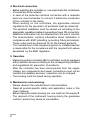
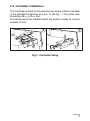
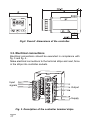
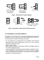
TEMPERATURE CONTROLLER RE21 TYPE USERS MANUAL 1 2 Contents 1. Application ........................................................................ 5 2. Controller set .................................................................... 5 3. Preparation of the controller to work ................................ 6 3.1. Safety ..................................................................................... 6 3.2. Controller installation .............................................................. 9 3.3. Electrical connection ............................................................ 10 3.4. Installation recommendations ................................................ 11 4. Starting to work .............................................................. 12 5. Programming of controller parameters .......................... 13 5.1. Scheme of the controller menu ........................................... 13 5.2. Change of the setting ........................................................... 15 5.3. List of parameters ................................................................ 16 6. Control ............................................................................ 17 6.1. ON-OFF control ................................................................... 17 6.2. PID control ........................................................................... 17 6.2.1. Choice of PID settings by the method of object identifying ........ 18 6.2.2. Choice of PID settings be the oscillation method ....................... 19 6.2.3. Correction of PID settings ........................................................... 19 7. Error signalling ................................................................ 20 8. Technical data ................................................................. 21 9. Execution and ordering codes ....................................... 23 10. Maintenance and guarantee ........................................ 24 3 4 1. APPLICATION The RE21 controller is destined to control temperature in furnaces, dryers, injection moulding machines and others. It co-operates directly with temperature sensors of resistance thermometer or thermocouple types. For thermocouples the temperature of cold ends is automatically compensated. The controller has a relay output with a shorted-opened configuration enabling the direct control of not big power objects. 2. CONTROLLER SET controller - 1 pc plug - 1 pc plug - 1 pc holder to fix in the panel - 2 pcs users manual - 1pc guarantee card - 1pc quick start card - 1pc When unpacking the instrument, please check whether the type and execution code on the data plate correspond to the order. 5 3. PREPARATION OF THE CONTROLLER TO WORK 3.1. Safety The RE21 controller fulfils requirements concerning the electrical safety of measuring instruments in automation acc. to EN 61010-1, and requirements concerning immunity against electromagnetic interference acc. to EN 61000-6-2 and emission of electromagnetic interference occurring in industrial environment acc. to EN 61000-6-4 BASIC REQUIREMENTS, SAFETY INFORMATION Symbols located in this service manual mean: WARNING! ? Warning of potential, hazardous situations. Especially important. One must acquaint with this before connecting the instrument. The non-observance of notices marked by these symbols can occasion severe injuries of the personnel and the damage of the instrument. CAUTION! Designates a general useful note. If you observe it, handling of the meter is made easier. One must take note of this, when the instrument is working inconsistently to the expectations. Possible consequences if disregarded ! In the security scope the meter meets the requirements of the EEC Low-Voltage Directive (EN 61010 -1 issued by CENELEC ). 6 Remarks concerning the operator safety: 1. General - The controller is destined to be mounted on a panel. - Non-authorized removal of the required housing, inappropriate use, incorrect installation or operation creates the risk of injury to personnel or damage to equipment. For more detailed information please study the Users Manual. - All operations concerning transport, installation, and commissioning as well as maintenance must be carried out by qualified, skilled personnel and national regulations for the prevention of accidents must be observed. - According to this basic safety information, qualified, skilled personnel are persons who are familiar with the installation, assembly, commissioning, and operation of the product and who have qualifications necessary for their occupation. 2. Transport, storage t Please observe the notes on transport, storage and appropriae handling. Observe the climatic conditions given in Technical Data. 3. Installation - The controller must be installed according to the regulation and instructions given in this Users Manual. - Ensure proper handling and avoid mechanical stress. - Do not bend any components and do not change any insulation distances. - Do not touch any electronic components and contacts. - Controllers may contain electrostatically sensitive components, which can easily be damaged by inappropriate handling. - Do not damage or destroy any electrical components since this might endanger your health! 7 4. Electrical connection - Before switching the controller on, one must check the correctness of connection to the network. - In case of the protection terminal connection with a separate lead one must remember to connect it before the connection of the controller to the mains. - When working on live controllers, the applicable national regulations for the prevention of accidents must be observed. - The electrical installation must be carried out according to the appropriate regulations (cable cross-sections, fuses, PE connection). Additional information can be obtained from the users manual. - The documentation contains information about installation in compliance with EMC (shielding, grounding, filters and cables). These notes must be observed for all CE-marked products. - The manufacturer of the measuring system or installed devices is responsible for the compliance with the required limit values demanded by the EMC legislation. 5. Operation - Measuring systems including RE21 controllers, must be equipped with protection devices according to the corresponding standard and regulations for prevention of accidents. - After the controller has been disconnected from the supply voltage, live components and power connections must not be touched immediately because capacitors can be charged. - The housing must be closed during operation. 6. Maintenance and servicing. - Please observe the manufacturers documentation. - Read all product-specific safety and application notes in this Users Manual. - Before taking the meter housing out, one must turn the suppl off. - The removal of the instrument housing during the guarantee contract period may cause its cancellation. 8 3.2. Controller installation The controller is fixed to the panel by two screw holders included in the standard accessory set, acc. to the fig. 1. The panel hole should be 45+0.6 x 45+0.6 mm. The thickness of the material which the panel is made of, cannot exceed 15 mm. Fig.1. Controller fixing. 9 Fig.2. Overall dimensions of the controller. 3.3. Electrical connections Electrical connections should be executed in compliance with fig. 3 and fig. 4. . Make electrical connections to the terminal strips and next, force in the strips into controller sockets. Input signals Output Supply Fig. 3. Description of the controller terminal strips. 10 Jointer Pt100 resistance thermometer in 2-wire system Pt100 resistance thermometer in 3-wire system thermocouple Fig.4. Connection of input signals. Supply Output - relay Output - binary voltage for SSR control Fig.5. Connection of the main and load circuits. 3.4. Installation recommendations To obtain a full immunity of the controller against electromagnetic interference in an unknown environment interference level it is recommended to observe following principles: - do not supply the controller from the network near devices generating high pulse interference and do not use common earthing circuits with them. - apply network filters, - apply metallic shields in the shape of tubes or braided screens to conduct supplying wires, - wires supplying the measuring signal should be twisted in pairs, and for resistance thermometers in a 3-wire connection, twisted from wires with the same length, cross-section and resistance, and led in a shield as above, 11 - all shields should be one-side earthed, and led the nearest possible to the controller, - apply the general principle that wires leading different signals should be led the farthest possible between them (not less than 30 cm), and the crossing executed of these groups of wires must be made at right angle. 4. STARTING TO WORK After the correct installation and supply connection, the controller carries out the display test and displays the type of controller re21, the program version and next, the measured value. A character message can appear on the display informing about abnormalities (table 2). The ON-OFF control algorythm with hysteresis = 2°C is set by the manufacturer. Change of the set value The set value is displayed after pressing the or key. The way to change the set value is shown on the fig.6.The return to display the measured value follows after pressing the key or after 30 seconds from the last pressure of the or key. Measured value Set value Change of the set value Fig.6. Change of the set value. 12 5. PROGRAMMING OF CONTROLLER PARAMETERS 5.1. Scheme of the controller menu The controller menu scheme is presented on the fig.7. After pressing and holding during at least 2 seconds the key, it is possible to program parameters. Transition between parameters is carried on by means of and keys. Some parameters can be invisible - this depends on the control algorythm selection. The return to the normal working mode follows after the simultaneand keys or automatically after the laps ous pressure of of 30 seconds since the last key pressure. 13 Fig.7. Servicing menu of the controller. 14 5.2. Change of setting The parameter setting change begins after the pressure of the key. The selection of the setting is carried out by and keys and accepted by the key. The change cancellation is carried out by a simultaneous pressure of and keys or automatically after 30 sec from the last key pressure. The way of the setting change is shown on the fig. 8. Start of changes Resignation of changes Acceptation of changes Decrease of value Increase of value Start of changes Resignation of changes Acceptation of changes Previous parameter Next parameter Fig.8. Change of settings for numerical and textual paramete. 15 5.3. List of parameters The list of controller parameters is presented in the table 1. List of configuration parameters Table 1 Parameter symbol Parameter description Manufacturer Range of parameter setting change Hy pb ti td Hysteresis1) 2.0 0.2...99.9 °C Proportional band2) 30.0 0.1...999.9 °C Integration time-constant3) 300 1...9999 s to Differentiation time-constant4) 60 1...9999 s Pulse period2) 20.0 0.5...99.9 s out Output configuration inu dir: direct control (cooling) inu: reverse control (heating) alg Control algorytm oNof oNof: control algorythm ON-OFF p: control algorythm P pd: control algorythm PD pid: control algorythm PID reso Position of the decimal point 1-dp 0_dp: without decimal point 1_dp: 1 decimal point The parameter is visible only for ON-OFF algorythm. The parameter is visible only for P, PD or PID algorythm. 3) The parameter is visible only for the PID algorythm. 4) The parameter is only visible for PD or PID algorythm. 1) 2) 16 6. CONTROL 6.1. ON-OFF control When a high accuracy of the temperature control is not required, especially with a great time-constant and a small delay, one can use the ON-OFF control with hysteresis. Advantages of this way of control is simplicity and reliability. However, the disadvantage is the occurrence of oscillations, even at small hysteresis values. Fig.9. Way of the output action of heating type for ON-OFF control. 6.2. PID control When we want to obtain a better temperature control accuracy, one must take advantages of the PID algorythm. The adjustment of the controller to the object relies on the value settlement of the integrating element, differentiating element and the output pulse period. 17 6.2.1. Choice of the PID settings by the method of the object identifying One must read out the delay time of the To object from the object characteristic presenting the controlled quantity in the function of time and the maximal accretion speed of the temperature from the dependence: Vmax = DPVmax Dt Calculate PID settings acc. to the given formulas: Pb = 1.1 . Vmax . T0 ti = 2.4 . T0 td = 0.4 . T0 18 - proportional band - integration time-constant - differentiation time-constant 6.2.2. Choice of PID settings by the oscillation method Set the ON-OFF control with the minimal hysteresis. Set the set value on the normal work level (or on lower level, if over-regulations could cause damages) and normal load conditions. Fig.10. Choice of settings by the oscillation method Calculate controller settings acc. to the given formulas: Pb = P ti = T td = 0.25 . T 6.2.3. Correction of PID settings It is recommended to match the parameters, changing the value into a twice higher or twice lower. During changes, one must be guided by following principles: a) Free answer of the jump: - decrease the proportional band, - decrease integration and differentiation times. 19 b) Over-regulations: - increase the proportional band, - increase the differentiation time. c) Oscillations: - increase the proportional band, - increase the integration time, - decrease the differentiation time. d) Instability: - increase the integration time. 7. ERROR SIGNALLING Character messages signaling the incorrect controller operation. Table 2 Error code Cause Procedure lerr Exceeding of the measuring range downward or lack of thermistor. Check if the chosen type of sensor is conform to the switched on. Check if values of input signals are contained in the appropriate range - if yes, check if a short-circuit does not occur in the resistance thermometer or if the thermocouple has not been inversely switched on. Herr Exceeding of the measuring range upward or break in the sensor circuit. Check if the chosen type of sensor is conform with the switched on. Check if values of input signals are contained in the appropriate range - if yes, check if there is no break in the sensor circuit. eRad Input discalibrated. Switch on again the controller supply and if this cannot help, contact the nearest authorized workshop. (upper display) 20 8. TECHNICAL DATA Input signal acc. to the table 3 Input signals and measuring ranges for inputs Table 3 Sensor/input type Marking Range [°C] Basic error [°C] Pt100 acc. to EN 60751+A2 Pt100 Pt100 Fe-CuNi acc. to EN 60584-1 Fe-CuNi Fe-CuNi NiCr-NiAl acc. to EN 60584-1 NiCr-NiAl NiCr-NiAl PtRh10-Pt acc. to EN 60584-1 Pt100 -50...100 0.8 Pt100 Pt100 J 0...250 0..600 0...250 1.3 3.0 3.0 J J K 0...600 0...900 0...600 4.0 5.0 4.0 K K S 0...900 0...1300 0...1600 5.0 6.0 7.0 Measurement time 0.5 s Error detection in the measuring circuit: - thermocouple, Pt100 exceeding of the measuring range Kind of output: - relay switching contact maximal load capacity: voltage: 250 V a.c.,150 V d.c. current: 5 A, 250 V a.c.,5 A, 30 V d.c. resistance load: 1250 VA, 150 W - binary voltage (without insulation from the sensor side) voltage 6 V +0.3 V, resistance limiting the current: 100 W Way of output action: - reverse for heating - direct for cooling 21 Signalling of: - active output - set value display Rated service conditions: - supply voltage - external magnetic field - preheating time - work position 230 V a.c. ±10% 110 V a.c. ±10% 24 V a.c. ±10% 50/60 Hz 0...23...50 °C -20...+70 °C < 85 % (inadmissible condensation) < 400 A/m 30 min any Power consumption < 3 VA Weight < 0.25 kg IP protection ensured through the housing acc. EN 60529 - from the frontal side - from terminals IP40 IP20 - supply voltage frequency ambient temperature storage temperature relative humidity Additional errors in rated working conditions caused by: - ambient temperature changes £100% of the basic error /10 K. Security requirements acc to EN 61010-1 - installation category - III, - pollution degree - 2, - maximal phase-to-earth work voltage: - for the supply circuit, outputs - 300 V - for input circuits - 50 V Electromagnetic compatibility - immunity acc. EN 61000-6-2 - emission acc. EN 61000-6-4 22 9. ORDERING CODES The coding way is given in the table 4 Temperature controller RE21 - Table 4 XX X XX X Input resist. thermometer Pt100 (-50...100OC) ..... 01 resist. thermometer Pt100 (0...250OC) ......... 02 resist. thermometer Pt100 (0...600OC) ......... 03 thermocouple Fe-CuNi (0...250OC) ........... 04 thermocouple Fe-CuNi (0...600OC) ........... 05 thermocouple Fe-CuNi (0...900OC) ........... 06 thermocouple NiCr-NiAl (0...600OC) .......... 07 thermocouple NiCr-NiAl (0...900OC) .......... 08 thermocouple NiCr-NiAl (0...1300OC) ........ 09 thermocouple PtRh10-Pt (0...1600OC) ......... 10 as ordered* ................................................. X Supply voltage: 230 V 50/60 Hz ................................................... 1 110 V 50/60 Hz .................................................... 2 24 V 50/60 Hz ..................................................... 3 as ordered* ......................................................... X Output: relay .......................................................................... 00 binary 0/6 V for SSR control ...................................... 01 without output ............................................................ 09 as ordered* ............................................................... XX Extra acceptance tests: without extra quality requirements ...................................... 0 with an extra quality inspection certificate .......................... 1 acc. agreement with the manufacturer** ............................ X * The code numbering is defined by the manufacturer ** After agreement with the manufacturer Example of ordering: Code RE21 - 03 - 2 - 00 - 0 means: 03 2 00 0 - Pt100 resistance thermometer as the input - supply = 110 V, 50/60 Hz - relay output - without extra quality requirements 23 10. MAINTENANCE AND WARRANTY The RE21 controller does not require any periodical maintenance. In case of some incorrect operations: 1. After the dispatch date and within the period stated in the warranty card One should return the instrument to the Manufacturers Quality Inspection Dept. If the instrument has been used in compliance with the instructions,the Manufacturer guaranties to repair it free of charge. The disassembling of the housing causes the cancellation of the granted warranty. 2. After the warranty period One should send the instrument to repair it in a authorized service workshop. Spare parts are available for the period of five years from the date of purchase. The Manufacturer reserves the right to make changes in design and specifications of any products as engineering advances or necessity requires. 24 25 LUMEL S.A.RE21/January 2006 Lubuskie Zak³ady Aparatów Elektrycznych - LUMEL S.A. ul. Sulechowska 1, 65-022 Zielona Góra, Poland Tel.: (48-68) 32 95 100 (exchange) Fax: (48-68) 32 95 101 www.lumel.com.pl e-mail:[email protected] Export Department: Tel.: (48-68) 329 53 02 or (48-68) 329 53 04 Fax: (48-68) 325 40 91 e-mail: [email protected] 26