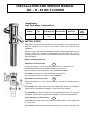
1
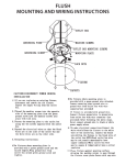
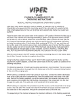
INSTALLATION AND SERVICE MANUAL
NIL – D - 69 WC FLUSHER
Installationand Operating - Instructions
WCflusher
Orderno.
D 69
122
Approval
Connection
Test Reg. No. Thread size
DIN DVGW
514
DN 20
¾“
Flow
Pressure
1,2 – 4,0 bar
INSTALLATION
Riser pipe: According to the regulations for the calculation of cold-water pipes in
plumbing systems as set out by the DVGW. Please also observe local
regulations.
Purge the water mains before installation of flusher. Install flusher with a 27mm
spanner. Please use a straight or cranked flush pipe with diam. 28 x 26 mm
according to DIN 3267. We recommend to fasten the flush pipe to the wall with a
flush-pipe clamp.
Water - saving made easy
Adjustment of the flush-rate
A
Factory pre-setting: 1.0 l/s (1.3 l/s) at a flow-pressure of 2.5 bar (4.0 bar).
To increase the flush-rate or adjust to a lower flow-pressure:
Turn the throttle screw 12 by approx. 1 turn counter-clockwise.
To reduce the flush-rate or adjust to a higher flow-pressure:
Turn the throttle screw 12 by approx. 1 turn clockwise.
Adjustment of the flush-volume
B
Factory pre-setting: 6.0 – 6.5 l at a flow-pressure of 2.5 bar and operating time of
1 second.
To increase the flush volume turn the adjustment screw 10 clockwise.
One full turn is equivalent to approx. 1 litre more flush volume.
To decrease the flush volume turn the adjustment screw 10 counterclockwise. One full turn is equivalent to approx. 1 litre less flush volume.
Proportioning of the flush volume
C
To decrease the flush volume only press the operating lever 3 down lightly and
for a short time.
To increase the flush volume press the operating lever 3 down for a longer time.
Flushpipe
diam.
28 x 26
mm
Operation and Operating Principle
The operating lever 3 is pressed. This causes the lifting sleeve to rise and the
auxiliary valve 8 to open and be pushed against the piston spring. This in turn
relieves the areas above and inside the piston of pressure. The operating lever
causes the piston to be pushed fully upwards. The flushing process has now
begun.
The operating lever is now released. This causes the auxiliary valve to close
the piston chamber. This now fills with water via the pressure balance bore, this
process causes the piston to be pressed down against the valve seat, the
pressure in the piston chamber now gradually builds up to the prevailing mains
pressure. The flushing process is now complete.
Spare parts
122/6K
Complete Piston
(piston 6, piston-nipple 9, piston lip-seal 19, piston-seal 21, lip-seal retaining
ring 24)
122/8K
Complete Auxiliary Valve
(auxiliary valve 8, auxiliary valve seal 20)
122/14K Complete Outlet Fitting
(outlet nut 14, tail-pipe 15, seal 22)
122/24 Set of Spare Parts
122/25 Set of Seals
Servicing and Trouble Shooting
1. Flusher flows continuously – Remove and clean the main piston:
Unscrew cover cap 2, unscrew auxiliary valve 8 and then take the main
piston out of the flusher body. Now clean all parts thoroughly. Clean the
pressure balance bore with a “NIL” bore-cleaning needle.
2. Flusher does not supply enough water, or operating time is too short:
Adjust throttle screw 12 – Replace piston sleeve 19.
D
= Pressure-Balance Bore
(Jet-Bore)
The efficient way to carry out repairs: “NIL” spare-part sets.
FRIEDRICH GAMPPER KG – METALLWARENFABRIK- D-71534 MURRHARDT
P.O. Box 1164 Phone + 49 (0) 7192 - 971 – 0 Fax + 49 (0) 7192 – 971- 105