1
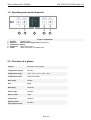
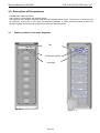
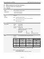
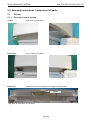
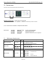
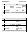
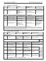
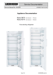
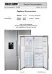
Service Documentation
After Sales Service International
Service Manual No. 06/2008
LHG/KDT-Ne/07.04.08
Appliance Documentation
GN 19.3
GN 23.3
GN 27.3
GN 30.3
from Index 20 Comfort
from Index 20 Comfort
from Index 20 Comfort
from Index 20 Comfort
NoFrost freezer
GN 1913
GN 2313
Page 1/22
06200800SM_gb.doc
Service Manual No. 06/2008
GN 19.3/23.3/27.3/30.3 from -20
Contents
1.0
2.0
3.0
3.1
4.0
4.1
Operating and control elements ...............................................................................................3
Functions at a glance.................................................................................................................3
Description of the appliance .....................................................................................................4
Sensor positions, schematic diagrams .........................................................................................4
Main components and their functions......................................................................................5
Electrical components and functions ............................................................................................5
4.1.1 General.................................................................................................................................................. 5
4.1.2 Freezer compartment............................................................................................................................ 6
4.2 Refrigeration components and functions ......................................................................................8
4.2.1 General.................................................................................................................................................. 8
4.2.2 Freezer compartment............................................................................................................................ 8
5.0 Assembly instructions / replacement of parts.........................................................................9
5.1 General.........................................................................................................................................9
5.1.1
5.1.2
5.1.3
5.1.4
Electronic control system ...................................................................................................................... 9
Electronic power module..................................................................................................................... 10
Bottom door hinge............................................................................................................................... 13
Door magnet, reed contact.................................................................................................................. 14
5.2 Freezer compartment .................................................................................................................15
5.2.1
5.2.2
5.2.3
5.2.4
5.2.5
6.0
6.1
6.2
7.0
7.1
7.2
7.3
7.4
7.5
8.0
8.1
Disengaging the parts locking the evaporator module, folding down the evaporator module............ 15
Evaporator sensor............................................................................................................................... 16
Air sensor ............................................................................................................................................ 16
Temperature fuse................................................................................................................................ 17
Fan ...................................................................................................................................................... 17
Technical data ..........................................................................................................................18
General.......................................................................................................................................18
Freezer compartment .................................................................................................................18
Service menu ............................................................................................................................19
Brief survey of service menu ......................................................................................................19
Manual defrosting (-15°C LED) ..................................................................................................20
Demo mode (-25°C LED) .........................................................................................................20
Panel test (-18°C LED) .............................................................................................................21
Service mode (-21°C LED) .......................................................................................................21
Error code, troubleshooting ....................................................................................................22
Table of error codes ...................................................................................................................22
Page 2/22
Service Manual No. 06/2008
GN 19.3/23.3/27.3/30.3 from -20
1.0 Operating and control elements
1
1
2
3
4
5
3
2
4
5
Freezer compartment
ON/OFF
ON/OFF button
Up/Down
Setting button higher/lower temperature
Temperature display
SuperFrost SuperFrost function
Alarm
Alarm OFF button for audible alarm
2.0 Functions at a glance
Control:
Electronic control system
Temperature display:
Set value
Temperature range:
-15°C, -18°C, -21°C, -25°C, -32°C
Temperature alarm:
Visual and audible
Door alarm:
Audible
Fan:
Fitted
Defrosting:
Automatic
Interior light:
Not fitted
Service menu:
Fitted
Compressor:
Standard
Solenoid valve
refrigeration circuit:
Not fitted
Page 3/22
Service Manual No. 06/2008
GN 19.3/23.3/27.3/30.3 from -20
3.0 Description of the appliance
The GN ..13 is a NoFrost freezer
with a series 3 control system with setpoint display.
The appliance has a lamellar evaporator with fan and integrated defrost heater. Two sensors, an air sensor and
an evaporator sensor, see to the control and automatic defrosting. A safety temperature limiter protects the
appliance against excessively high temperatures during the defrosting phase.
3.1
Sensor positions, schematic diagrams
Fan
Evaporator sensor
Air sensor
Fig. 3.1 / 1
Fig. 3.1 / 2
Page 4/22
Service Manual No. 06/2008
GN 19.3/23.3/27.3/30.3 from -20
4.0
Main components and their functions
4.1
Electrical components and functions
4.1.1
General
Electronic control system
Type:
Series 3 electronic control system
Components:
- Control panel electronics
- Power module electronics
Compressor
Type:
Standard
Function:
ON:
Air sensor switch-on value.
Note: On-delay time (8 minutes) must have elapsed.
OFF: Air sensor switch-off value
or
during defrosting
Switch
Door switch:
Position:
In front panel
Type:
Reed contact
Contact type: Make contact
Function:
Activation via:
magnet on the door, magnet is replaceable.
Switching signal when:
door closed:
fan
ON
door open:
fan
door alarm
OFF
ON after 60 seconds
Loads
Fan:
Position:
In the evaporator module, at the back centre.
Function:
Evaporator
Compressor
Door
Fan
sensor
Switch on
OFF
CLOSED
OFF
value
Switch on
ON
CLOSED
ON
value
Switch on
ON/OFF
OPEN
OFF
value
Switch off
ON/OFF
CLOSED/OPEN
OFF
value
e.g. If the evaporator sensor has reached the switch on value for the fan and the
compressor is ON and the door is closed, then the fan is ON.
Switch-on value evaporator sensor:
a) during start-up: -25°C
b) In the normal mode 2K colder than air sensor
Page 5/22
Service Manual No. 06/2008
4.1.2
GN 19.3/23.3/27.3/30.3 from -20
Freezer compartment
Electronic control system
Setting range:
-15°C / -18°C / -21°C / -25°C / -32°C
Display range:
-15°C / -18°C / -21°C / -25°C / -32°C
Functions
Temperature alarm:
Defrosting:
Alarm value:
4K warmer than set value.
Warmest alarm value:
-10 °C
Coldest alarm value:
-20 °C
Delay:
20 minutes
Visual:
Flashing alarm LED
Audible:
4 beeps (suppressed during start-up).
The defrosting phase is initiated:
- During start-up after 3 hours cumulative compressor running time.
- After a cumulative compressor running time of 3 to 60 hours maximum,
depending on the number/duration of the door openings.
As the defrosting phase begins, the compressor and fan are switched OFF and
the defrost heater is switched ON.
The defrost heater remains switched ON until such time as
- the freezer evaporator sensor has reached +22°C
or
- a max. defrosting time of 50 minutes has been reached.
After the end of the heating phase, the compressor is switched ON with a 10minute delay. Fan ON, from -25°C.
If the SuperFrost function is activated during the defrosting phase, this will not
interrupt defrosting.
Door alarm:
SuperFrost:
When:
If door is open after 60 seconds.
Audible:
3 beeps.
SuperFrost activated:
Cooling of the freezer compartment with full refrigeration performance (timecontrolled, 65 hours).
SuperFrost deactivated:
The appliance sets itself to the set value.
Sensors
Air sensor:
Evaporator sensor:
Position:
Behind the front panel of the evaporator module.
Function:
- Switches the compressor ON/OFF.
Position:
Slipped into the lamellar evaporator.
Function:
- Ends the defrosting phase.
- Switches the fan ON/OFF.
Page 6/22
Service Manual No. 06/2008
GN 19.3/23.3/27.3/30.3 from -20
Loads
Fan:
Position:
In the evaporator module, at the back centre.
Function:
Evaporator
Compressor
Door
Fan
sensor
Switch on
OFF
CLOSED
OFF
value
Switch on
ON
CLOSED
ON
value
Switch on
ON/OFF
OPEN
OFF
value
Switch off
ON/OFF
CLOSED/OPEN
OFF
value
e.g. If the evaporator sensor has reached the switch on value for the fan and the
compressor is ON and the door is closed, then the fan is ON.
Switch-on value evaporator sensor:
a) during start-up: -25°C
b) In the normal mode 2K colder than air sensor
Defrost heater:
Position:
Clipped into lamellar evaporator
Function:
Control via electronic system.
Defrost heater ON:
- Depending on the number and duration of door openings, the
electronic system calculates the defrost cycles between
3-60 hours cumulative compressor running time.
- Upon start-up after 3 hours cumulative
compressor running time.
Defrost heater OFF:
- When the evaporator sensor has reached +22°C
- When max. time of 50 minutes is exceeded.
Heater cannot be replaced Æonly complete evaporator module!
Page 7/22
Service Manual No. 06/2008
4.2
4.2.1
GN 19.3/23.3/27.3/30.3 from -20
Refrigeration components and functions
General
Compressor
Compressor:
Standard
Frame heater
Position:
4.2.2
Foamed-in in the housing, in the region of the magnetic door seal.
Freezer compartment
Evaporator
Type of design:
Lamellar evaporator
Type of installation:
In evaporator module on appliance ceiling
Injection point:
Front centre
Flow sequence:
Front to back
Page 8/22
Service Manual No. 06/2008
GN 19.3/23.3/27.3/30.3 from -20
5.0 Assembly instructions / replacement of parts
5.1
General
5.1.1
Electronic control system
Covers:
Remove using screwdriver.
Fig. 5.1.1/ 1 Cover left fastening screw
Front panel:
Fig. 5.1.1/ 2 Cover right fastening screw
Undo screws of front panel.
Fig. 5.1.1/ 3 Left screw
PCB carrier:
Fig. 5.1.1/ 4 Right screw
Raise and rest the front panel and disengage the PCB carrier.
Reed
Fig. 5.1.1/ 5 PCB carrier in front panel
Page 9/22
Service Manual No. 06/2008
Electronic control system:
GN 19.3/23.3/27.3/30.3 from -20
Disengage electronic module from PCB carrier.
Fig. 5.1.1/ 6 PCB carrier and electronic module
5.1.2
Electronic power module
Attention:
Pull out the power plug!
Electronic power module cover:
- Disengage marked retaining clips.
- Swing out the cover at the bottom and lift for removal.
Fig. 5.1.2 / 1
Cable clip:
Fig. 5.1.2 / 2
- Disengage the cable clip (transparent plastic clip) at the marked location.
Page 10/22
Service Manual No. 06/2008
GN 19.3/23.3/27.3/30.3 from -20
- Detach front PCB edge connector
- Release strain relief of supply cable.
- Disengage plug-in module at the right and left clip and draw it forwards for
removal.
Strain relief
Fig. 5.1.2 / 3
Plug-in module:
- Detach rear PCB edge connector.
Fig. 5.1.2 / 4
Electronic power module:
- Disengage the locking hooks at the "holder for capacitors".
- Disengage electronic power module at the marked locations (Fig. 5.1.2/ 6).
Holder for
capacitors
Fig. 5.1.2 / 5
Page 11/22
Service Manual No. 06/2008
GN 19.3/23.3/27.3/30.3 from -20
Fig. 5.1.2 / 6
Page 12/22
Service Manual No. 06/2008
5.1.3
GN 19.3/23.3/27.3/30.3 from -20
Bottom door hinge
Turn hinge cover:
Disengage the cover in the marked direction and draw it forwards for removal
(Fig. 5.1.3/ 1).
Bearing pin:
Retract the adjustable foot and press the bearing pin downwards. Then swing out the
door at the bottom and draw it out of the upper bearing pin (Fig. 5.1.3/ 2).
Notch has to point forwards for re-assembly.
Notch
Fig. 5.1.3/ 1 Turn hinge cover
Fig. 5.1.3/ 2 Bearing pin
Spring clip:
Depress the holder and remove the spring clip. Has to be transferred to the opposite
side if the door hinges are changed (Fig. 5.1.3/ 3).
Bottom bearing part:
Bottom bearing part has to be transferred if the door hinges are changed (Fig. 5.1.3/ 4).
Slot:
Screw can be transferred to slot for better door adjustment (Fig. 5.1.3/ 4).
Spring clip
Slot
Holding clip
Abb. 5.1.3/ 3 Spring clip
Bottom
b i
Fig. 5.1.3 / 4
Page 13/22
Service Manual No. 06/2008
5.1.4
GN 19.3/23.3/27.3/30.3 from -20
Door magnet, reed contact
Magnet holder:
The holder of the door magnet is located on the top edge of the door and can be
levered off.
Magnet
Fig. 5.1.4/ 1 Door magnet, magnet holder
Reed contact :
The reed contact is in the front housing.
Reed
Fig. 5.1.4/ 2 Reed contact
Page 14/22
Service Manual No. 06/2008
5.2
GN 19.3/23.3/27.3/30.3 from -20
Freezer compartment
5.2.1 Disengaging the parts locking the evaporator module, folding down the evaporator
module
Evaporator module
Locking
Remove top drawers
Fig. 5.2.1/ 1 Evaporator module
Locking parts:
Are snapped into place at the right and left for locking the evaporator module.
Transit support:
Remove adhesive tape securing the "top polystyrene moulding" in transit,
is no longer needed for assembly.
Top polystyrene moulding:
Lift off the polystyrene moulding first at the front, then at the back.
Draw the "top polystyrene moulding" forwards for removal.
Fig. 5.2.1/ 2 Remove locking part
Fig. 5.2.1/ 3 Remove adhesive tape
Page 15/22
Service Manual No. 06/2008
5.2.2
GN 19.3/23.3/27.3/30.3 from -20
Evaporator sensor
Evaporator module:
Dismantle evaporator module as described under, 5.2.1 Disengaging the parts
locking the evaporator module.
Evaporator sensor:
Is slipped inbetween the lamellas and in case of defect it has to be cut off and repaired
with the repair kit (Art. No. 9590 062).
Temperature fuse
Evaporator
Fig. 5.2.2/ 1 Evaporator module folded down
5.2.3
Air sensor
Evaporator module:
Dismantle evaporator module as described under, 5.2.1 Disengaging the parts
locking the evaporator module.
Front polystyrene moulding: Is situated behind the front panel of the evaporator module.
Acts as an air seal of the air sensor in the direction of the lamellar evaporator.
Air sensor:
Is engaged behind the front panel of the evaporator module and in case of defect it
has to be cut off and repaired with the repair kit (Art. No. 9590 062).
Fig. 5.2.3/ 1 Removal of the polystyrene
Fig. 5.2.3/ 2 Air sensor
Page 16/22
Service Manual No. 06/2008
5.2.4
GN 19.3/23.3/27.3/30.3 from -20
Temperature fuse
Evaporator module:
Dismantle the evaporator module as described under 5.2.1 Disengaging the parts
locking the evaporator module.
Temperature fuse:
Fastened by a screw. (see Fig. 5.2.2/ 1 Evaporator module folded down)
Please note in case of replacement:
- Cut off only at the coloured wires (not heater wire!)
- Fix the wires in such a way that they do not touch the heater.
5.2.5
Fan
Evaporator module:
Dismantle evaporator module as described under, 5.2.1 Disengaging the parts
locking the evaporator module.
Safety plate
Fan:
Lift out of the guide.
Safety plate is used for support in transit to prevent the fan from becoming detached.
Fan blade:
Press the fan blade off the fan shaft using your thumbs.
Fan:
Swing the fan out of the seat.
Take care: As the fan is swung out, the lower clip of the fan housing may get caught in
the rubber mount and break.
Upper clip
Rubber mount
Fig. 5.2.5/ 1 Safety plate, fan
Fig. 5.2.5/ 2 Dismantling fan blade
Page 17/22
Service Manual No. 06/2008
GN 19.3/23.3/27.3/30.3 from -20
6.0 Technical data
6.1
General
Sensor values:
6.2
Air and evaporator sensor
Temperature °C
Resistance value kOhm
+35
+30
+25
+20
+15
+10
+5
0
-5
-10
-15
-20
-25
-30
-35
3.1
3.8
4.7
5.9
7.3
9.3
11.9
15.3
19.8
25.9
34.1
45.3
60.8
82.3
112.8
Freezer compartment
Wattage:
Voltage:
Speed:
Direction of rotation:
4.5
watts
230
volts
2500 rpm
right (as viewed onto shaft), left (as viewed in the direction of
the evaporator module)
Wattage:
Voltage:
Speed:
Direction of rotation:
1.9
watts
230
volts
2500 rpm
right (as viewed onto shaft), left (as viewed in the direction of
the evaporator module)
Defrost heater:
Wattage:
Voltage:
259
230
Temperature fuse:
Tripping temperature:
93°C
Fan:
GN ..13
Fan:
GN ..23
watts
volts
Page 18/22
Service Manual No. 06/2008
7.0
GN 19.3/23.3/27.3/30.3 from -20
Service menu
The service menu may be used by service technicians only.
Activation of service menu:
Appliance has to be switched ON
Press "Up/Down" + "ON/OFF" simultaneously for about 5 seconds
Once the service menu is activated, the "SuperFrost LED" flashes.
Service menu:
Manual defrosting
Panel test
Service mode
Demo mode
No function
activation of the defrost heater
Test of controls and displays
Addressing electric loads
Appliance is switched ON, without refrigeration
Brief survey of service menu
Service menu
Demo mode
Panel test
Service mode
Å Up/Down button Æ
Manual defrosting
Menu
Opera
tion
-15°C LED
1x SF
-25°C LED
static
Selection of functional part
Defrosting activated
-15°C LED and -32°C LED
flash alternately with SuperFrost LED
Demo mode activated
1x SF
-25°C LED
flashes fast
-18°C LED
-21°C LED
Demo mode deactivated
1x SF
1x SF
Press buttons, door sensor
Å Up/Down button Æ
7.1
-15°C LED:
-18°C LED:
-21°C LED:
-25°C LED:
-32°C LED:
LEDs OFF
: All OFF
-15°C LED
: Compressor ON
-15°C LED,
-18°C LED
: Fan ON
-21°C LED
: Defrost heater ON
Page 19/22
Service Manual No. 06/2008
GN 19.3/23.3/27.3/30.3 from -20
7.2
Manual defrosting (-15°C LED)
Step
Display
Operation
Display following
operation
Service menu start
1
Set value
Testing option / Info
SF = SuperFrost
Press
"Up/Down" and
"ON/OFF"
simultaneously for 5
seconds
-15°C LED static
SuperFrost LED flashes
Servicemenu active
Manual defrosting
selected
-15°C LED + -32°C LED
flash alternately with
SF LED
Manual defrosting
activated
Manual defrosting -- activation of the defrost heater -2
End
-15°C LED static
SuperFrost LED flashes
Press "SF"
Appliance switch OFF or automatic when defrost parameters reached.
During manual defrosting, the -15°C LED and -32°C LED always flash alternately with the SuperFrost LED.
The setpoint value can be set and and is also displayed, then return to manual defrosting display.
7.3
Demo mode (-25°C LED)
Step
Display
Operation
Display following
operation
SF = SuperFrost
Start service
1
Set value
Testing option / Info
Press
"Up/Down" and
"ON/OFF"
simultaneously for 5
seconds
-15°C LED static
SuperFrost LED flashes
Service menu active
Demo mode ON
2
-15°C LED static
SuperFrost LED flashes
Press "Up/Down" once
-25°C LED static
SuperFrost LED flashes
Demo mode
seleceted
3
-25°C LED static
SuperFrost LED flashes
Press "SF" once
Setpoint
-18°C LED
Demo mode ON
Press "SF" once
-18°C LED lights up briefly,
then temperature display is
Demo mode OFF
dark until set temperature
is reached
Demo mode OFF
2
-25°C LED fast flash
SuperFrost LED flashes
If the appliance is switched OFF and ON again when the demo mode is activated, all the temperature LEDs are lit for
3 seconds as indication of the activated demo mode.
Demo mode can be deactivated only via service menu, not by OFF/ON or disconnection from the supply.
Page 20/22
Service Manual No. 06/2008
GN 19.3/23.3/27.3/30.3 from -20
7.4
Panel test (-18°C LED)
Step
Display
Operation
Display following
operation
Service menu start
1
Testing option / Info
SF = SuperFrost
Press
"Up/Down" and
"ON/OFF"
simultaneously for 5
seconds
Set value
-15°C LED static
SuperFrost LED flashes
Service menu active
Panel test -- test of sensor buttons, display elements, door sensor and beep -2
-15°C LED static
SuperFrost LED flashes
Press "Up/Down" twice
-18°C LED static
SuperFrost LED flashes
3
-18°C LED static
SuperFrost LED flashes
Press "SF" once
All temperature LEDs ON, Panel test
all button LEDs ON
activated
All temperature LEDs ON,
all button LEDs ON
Door open/closed
and
press all buttons one after - Beep for 2 sec.
the other
- appliance switches OFF
(each operation is
confirmed by beep)
4
Panel test selected
After the last button
has been pressed a
beep sounds for 2
seconds, only if the
test has been
successful.
Panel test cannot be ended in step 2, for example, it has to be performed in full.
Should a button/sensor be defective, there will be no 2-second beep and the appliance will not switch OFF.
The appliance then has to be unplugged and plugged back in again.
7.5
Service mode (-21°C LED)
Step
Display
Operation
Display following
operation
Testing option / Info
Service menu start
1
Set value
SF = SuperFrost
Press
"Up" and "ON/OFF" -15°C LED static
Service menu active
simultaneously for 5 SuperFrost LED flashes
seconds
Service mode -- testing electric loads--
Power
input
2
-15°C LED static
Press "Up/Down"
SuperFrost LED flashes three times
-21°C LED static
Service mode selected
SuperFrost LED flashes
6=>3
-21°C LED static
Press "SF" once
SuperFrost LED flashes
All temperature LEDs
OFF, SuperFrost LED
flashes fast
Service mode activated / All
OFF
4
All temperature LEDs
OFF, SuperFrost LED
flashes fast
Press "Up/Down"
once
-15°C LED and
SuperFrost LED flash
Compressor ON
---
5
-15°C LED and
SuperFrost LED flash
Press "Up/Down"
once
-15°C LED, -18°C LED
and SuperFrost LED
flash
Fan ON
4.5 watts
-21°C LED and
SuperFrost LED flash
Defrost heater ON 259 watts
3<=6
End
-15°C LED, -18°C LED
Press "Up/Down"
and SuperFrost LED
once
flash
Press "ON/OFF" twice: Return to normal/control mode
Page 21/22
Service Manual No. 06/2008
GN 19.3/23.3/27.3/30.3 from -20
8.0 Error code, troubleshooting
8.1
Table of error codes
Error code
Defective component
Emergency mode
-15°C + -18°C + -21°C LED
- Continuous compressor operation
flash in synchronism with
Freezer compartment air sensor
- Continuous fan operation
SF LED
-15°C + -25°C LED
flash in synchronism with
SF LED
Freezer compartment
evaporator sensor
- Continuous compressor operation
- Continuous fan operation
Page 22/22