1
kÉï=~ë=çÑW==
MQKOMNP
d^ifiblp
~ë=çÑ=råáí=ëçÑíï~êÉ=sMQKNOKMM
pÉêîáÅÉ=j~åì~ä=E~ë=çÑ=cÉÄêì~êó=OMNPF
båÖäáëÜ
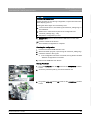
GALILEOS Service Manual
=
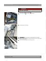
Sirona Dental Systems GmbH
Service Manual (as of February 2013) GALILEOS
1
2
3
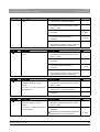
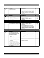
About this Service Manual.......................................................................................
11
1.1
Scope ...........................................................................................................
11
1.2
Other documentation required......................................................................
11
1.3
Tools and auxiliary materials........................................................................
11
1.4
Structure of the document ............................................................................
12
1.4.1 Identification of the danger levels......................................................
12
1.4.2 Formats and symbols used ...............................................................
12
Safety instructions ...................................................................................................
14
2.1
Modifications to the unit................................................................................
14
2.2
Fixed connection ..........................................................................................
14
2.3
Electromagnetic compatibility.......................................................................
14
2.4
Electrostatic discharge .................................................................................
14
2.5
Switching the unit on ....................................................................................
14
2.6
Condensation ...............................................................................................
15
2.7
Laser light localizer.......................................................................................
15
2.8
Ventilation slots ............................................................................................
15
2.9
Qualifications of service personnel...............................................................
15
2.10
Radiation protection .....................................................................................
15
2.11
Safety checks ...............................................................................................
15
Unit description........................................................................................................
16
3.1
Unit classes and versions.............................................................................
16
3.1.1 Control panels ...................................................................................
17
Hardware......................................................................................................
17
3.2.1 Information on the unit ......................................................................
17
3.2.2 Installation versions...........................................................................
18
3.2.3 Modules and components .................................................................
19
3.2.3.1 Slide ................................................................................................
20
3.2.3.2 Stand ...............................................................................................
21
3.2.3.3 Remote control ................................................................................
21
3.2.3.4 FaceScan ........................................................................................
22
3.2.4 Cabling overview...............................................................................
23
3.2.5 Board photos.....................................................................................
28
3.2
64 26 345 D3437
D3437.076.03.02.02
04.2013
3
båÖäáëÜ
Table of contents
Sirona Dental Systems GmbH
Service Manual (as of February 2013) GALILEOS
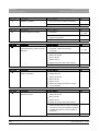
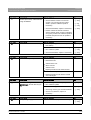
3.2.5.1 Boards in the slide............................................................................
28
3.2.5.2 Boards in the stand ..........................................................................
33
3.2.5.3 Board in the remote control ..............................................................
34
3.2.5.4 FaceScan boards .............................................................................
34
3.2.6 Covers................................................................................................
36
3.2.7 Technical data....................................................................................
38
3.2.7.1 GALILEOS Compact/GALILEOS Comfort .......................................
38
3.2.7.2 GALILEOS Comfort PLUS ...............................................................
40
Software/compatibility ...................................................................................
43
3.3.1 GALILEOS firmware...........................................................................
43
3.3.2 FaceScan firmware ............................................................................
44
3.3.3 GALILEOS Software ..........................................................................
44
General operating procedures..................................................................................
45
4.1
Switching the unit on .....................................................................................
45
4.1.1 Switching the "GALILEOS Comfort / Comfort PLUS" on ...................
45
4.1.2 Switching the "GALILEOS Compact" on ............................................
46
4.1.3 Factory setting after switch-on ...........................................................
46
Updating the firmware ...................................................................................
47
4.2.1 Updating the unit firmware .................................................................
47
4.2.1.1 Update mode....................................................................................
51
4.2.1.2 Check program releases ..................................................................
53
4.2.2 Updating the FaceScan firmware.......................................................
54
4.2.2.1 Option 1: Update using the FaceScan USB stick.............................
54
4.2.2.2 Option 2: Firmware update via the network .....................................
56
Configuring the unit .......................................................................................
58
4.3.1 Configuring the unit via the SIDEXIS Manager ..................................
58
4.3.1.1 Setup of an X-ray component ..........................................................
58
4.3.2 Configuring FaceScan........................................................................
66
4.3.2.1 Type 1: Configuration using the Facescan USB stick ......................
66
4.3.2.2 Type 2: Configuration over a network cable (peer-to-peer) .............
68
4.3.2.3 Resetting the FaceScan configuration to factory default settings ....
69
Reading unit data ..........................................................................................
70
4.4.1 Reading the unit data of the GALILEOS via "Extended Details"........
70
4.4.2 Reading FaceScan unit data over the network ..................................
72
3.3
4
4.2
4.3
4.4
4
64 26 345 D3437
D3437.076.03.02.02 04.2013
Sirona Dental Systems GmbH
4.5
5
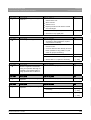
Using demo mode – operation without radiation release .............................
73
4.5.1 Switching on demo mode..................................................................
73
4.5.2 Switching off demo mode..................................................................
74
4.5.3 Important information for repacking and transport ............................
75
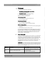
Messages ................................................................................................................
77
5.1
Help messages.............................................................................................
77
5.2
System messages ........................................................................................
78
5.3
Status messages and displays.....................................................................
78
5.4
Error messages ............................................................................................
79
5.4.1 Error code: Ex yy zz ..........................................................................
79
5.4.2 Ex - Error type ...................................................................................
79
5.4.3 yy - Location......................................................................................
81
5.4.4 General handling of error messages .................................................
81
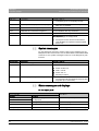
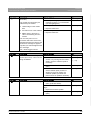
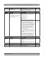
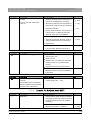
List of error messages..................................................................................
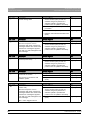
82
5.5.1 Location 06: Tube assembly/DX6 .....................................................
82
5.5.2 Location 07: Easypad/DX7................................................................
87
5.5.3 Location 10: System hardware..........................................................
91
5.5.4 Location 11: Power PC/Board DX11.................................................
93
5.5.5 Location 12: CAN bus .......................................................................
96
5.5.6 Location 13: Stand/Peripherals .........................................................
97
5.5.7 Location 14: Digital extension, SIDEXIS XG .....................................
102
5.5.8 Location 15: Configuration, update ...................................................
104
5.5.9 Location 42: Remote control .............................................................
105
5.5.10 Location 71: Multipad, board DX71...................................................
109
5.5.11 Location 89: X-ray detector ...............................................................
113
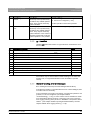
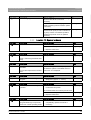
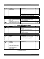
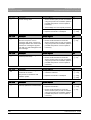
Troubleshooting.......................................................................................................
119
6.1
Error logging memory...................................................................................
119
6.1.1 Example of error logging data ...........................................................
120
Checking the CAN bus .................................................................................
121
6.2.1 Checking the CAN bus with the diagnostic function of board DX1 ...
125
6.2.2 Jumper positions in the CAN bus ......................................................
125
Checking the boards ....................................................................................
127
6.3.1 Checking board DX32 .......................................................................
129
6.4
Checking the motors ....................................................................................
131
6.5
Checking the light barriers............................................................................
132
5.5
6
6.2
6.3
64 26 345 D3437
D3437.076.03.02.02
04.2013
5
båÖäáëÜ
Service Manual (as of February 2013) GALILEOS
Sirona Dental Systems GmbH
Service Manual (as of February 2013) GALILEOS
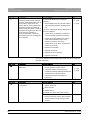
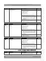
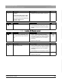
6.6
Device leakage current too high.................................................................... 133
6.7
Checking the cables ...................................................................................... 133
6.8
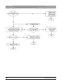
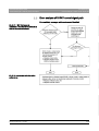
Error analysis of X-RAY control signal path .................................................. 135
6.8.1 Error analysis of X-RAY control signal path: from unit serial number
3201 (without board DX41)
6.9
138
Fault diagnosis of the X-ray detector and on board DX89 ............................ 141
6.9.1 LEDs on board DX89 ......................................................................... 141
6.9.2 LED statuses and their significance in case of an error ..................... 142
6.9.3 LEDs of operating voltages ................................................................ 144
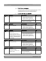
7
Adjusting and calibrating the unit ............................................................................. 145
7.1
General information about unit adjustment and calibration ........................... 146
7.1.1 Displays and help messages during adjustment/calibration .............. 147
7.1.2 "Adjustment/Calibration" menu .......................................................... 147
7.1.2.1 Calling the "Adjustment/Calibration" menu....................................... 147
7.1.2.2 Menu structure ................................................................................. 149
7.1.3 Enabling exposure readiness............................................................. 151
7.1.4 Taking an exposure............................................................................ 151
7.1.5 Save values........................................................................................ 152
7.1.6 Test phantoms for adjustment and calibration ................................... 152
7.1.6.1 Distortion phantom ........................................................................... 152
7.1.6.2 Geometry phantom .......................................................................... 152
7.1.6.3 Constancy test phantom .................................................................. 154
7.2
Checking the mechanical system adjustment ............................................... 154
7.3
Adjustment and calibration via the "Service Functions" menu ...................... 155
7.3.1 Diaphragm image............................................................................... 155
7.3.2 Checking the radiation field................................................................ 161
7.3.3 Dosimetry ........................................................................................... 162
7.3.4 Sensor adjustment ............................................................................. 163
7.3.5 Iris adjustment.................................................................................... 164
7.3.6 Shading calibration............................................................................. 165
7.3.7 Distortion calibration........................................................................... 166
7.3.8 Geometry calibration .......................................................................... 167
7.4
Performing a white balance for FaceScan .................................................... 168
7.5
Mechanical adjustments................................................................................ 169
7.5.1 Ring center adjustment ...................................................................... 169
7.5.2 Adjusting the swivel arm .................................................................... 170
7.5.3 Diaphragm adjustment ....................................................................... 171
6
64 26 345 D3437
D3437.076.03.02.02 04.2013
Sirona Dental Systems GmbH
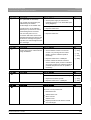
8
Perform service routines via the control panel ........................................................
174
8.1
Overview of service routines ........................................................................
174
8.1.1 List of all service routines available for selection ..............................
174
8.1.2 Alphabetical list of service routine functions .....................................
175
Service menu and service routines ..............................................................
177
8.2.1 Displays and symbols in the service menu .......................................
177
8.2.1.1 Easypad ..........................................................................................
177
8.2.1.2 Multipad...........................................................................................
178
Basic operating procedures in the service menu .........................................
180
8.3.1 Activating the service menu ..............................................................
180
8.3.1.1 Easypad ..........................................................................................
180
8.3.1.2 Multipad...........................................................................................
182
8.3.2 Selecting service routines and test steps ..........................................
182
8.3.2.1 Selecting a service routine ..............................................................
182
8.3.2.2 Selecting a test step ........................................................................
183
8.3.2.3 Service routines with security access..............................................
185
8.3.3 Select parameters .............................................................................
187
8.3.4 Saving parameters ............................................................................
188
8.3.5 Exiting the test step and service routine ...........................................
190
S002: Radiation without rotary movement, selectable kV/mA level and
maximum radiation time
191
8.4.1 S002: Test step 5 ..............................................................................
191
S005: General X-ray tube assembly service ................................................
192
8.5.1 S005: Test step 4 ..............................................................................
193
8.5.2 S005: Test step 5 ..............................................................................
193
8.5.3 S005: Test step 8 ..............................................................................
194
S007: Error logging memory ........................................................................
196
8.6.1 S007: Test step 1 ..............................................................................
196
8.6.2 S007: Test step 2 ..............................................................................
198
8.6.3 S007: Test step 5 ..............................................................................
200
8.6.3.1 Displaying the log with a web browser ............................................
201
S008: Update service ...................................................................................
203
8.7.1 S008: Test step 2 ..............................................................................
203
8.7.2 S008: Test step 3 ..............................................................................
204
8.2
8.3
8.4
8.5
8.6
8.7
64 26 345 D3437
D3437.076.03.02.02
04.2013
7
båÖäáëÜ
Service Manual (as of February 2013) GALILEOS
Sirona Dental Systems GmbH
Service Manual (as of February 2013) GALILEOS
8.8
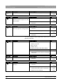
S009: Flash file system ................................................................................. 205
8.8.1 S009: Test step 4 ............................................................................... 205
8.8.2 S009: Test step 5 ............................................................................... 207
8.8.3 S009: Test step 7 ............................................................................... 209
8.9
S011: Dosimetry (without ring movement) .................................................... 211
8.9.1 S011: Test step 9 ............................................................................... 211
8.9.2 S011: Test step 12 ............................................................................. 212
8.10
S012: CAN bus service ................................................................................. 213
8.10.1 S012: Test step 1 ............................................................................... 213
8.10.2 S012: Test step 2 ............................................................................... 215
8.10.3 S012: Test step 3 ............................................................................... 216
8.10.4 S012: Test step 4 ............................................................................... 217
8.11
S017: Configuration service .......................................................................... 218
8.11.1 S017: Test step 2 ............................................................................... 218
8.11.2 S017: Test step 3 ............................................................................... 220
8.11.3 S017: Test step 4 ............................................................................... 221
8.11.4 S017: Test step 5 ............................................................................... 222
8.11.5 S017: Test step 6 ............................................................................... 223
8.11.6 S017: Test step 7 ............................................................................... 225
8.11.7 S017: Test step 13 ............................................................................. 226
8.11.8 S017: Test step 14 ............................................................................. 227
8.11.9 S017: Test step 15 ............................................................................. 229
8.11.10S017: Test step 25 ............................................................................ 230
8.12
S018: Service for height adjustment ............................................................. 232
8.12.1 S018: Test step 2 ............................................................................... 232
8.12.2 S018: Test step 3 ............................................................................... 233
8.12.3 S018: Test step 4 ............................................................................... 234
8.12.4 S018: Test step 5 ............................................................................... 235
8.12.5 S018: Test step 6 ............................................................................... 236
8.13
S037: Network service .................................................................................. 237
8.13.1 S037: Test step 1 ............................................................................... 237
8.13.2 S037: Test step 2 ............................................................................... 239
8.13.3 S037: Test step 3 ............................................................................... 241
8.13.4 S037: Test step 4 ............................................................................... 243
8
64 26 345 D3437
D3437.076.03.02.02 04.2013
Sirona Dental Systems GmbH
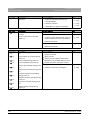
9
Repair ......................................................................................................................
249
9.1
Safety checks ...............................................................................................
250
9.2
Height adjustment motor (M1_4)/spindle......................................................
250
9.2.1 Preparing for motor replacement ......................................................
250
9.2.1.1 Moving the slide manually ...............................................................
251
9.2.2 Removing board DX32......................................................................
254
9.2.3 Replacing the height adjustment motor/spindle ................................
255
9.2.4 Laying of cables when replacing the height adjustment motor .........
257
9.2.5 What has to be done after replacing the height adjustment motor
(M1_4) or the spindle?
260
Ring motor (M1_3)........................................................................................
261
9.3.1 Replacing the ring motor ...................................................................
261
9.3.2 Replacing the pinion at the ring motor ..............................................
262
9.3.3 Laying of cables when replacing the ring motor ................................
263
9.3.4 What has to be done after replacing the ring motor (M1_3)/pinion? .
264
Rotary knob on the swivel arm .....................................................................
264
9.4.1 Replacing the rotary knob .................................................................
264
Control panel ................................................................................................
265
9.5.1 Replacing Easypad or Multipad user interface..................................
265
9.5.1.1 What has to be done after replacing the user interface?.................
266
9.5.2 Laying of cables when replacing the user interface ..........................
267
X-ray tube unit ..............................................................................................
268
9.6.1 Replacing the X-ray tube assembly (GALILEOS Compact/
GALILEOS Comfort)
268
9.6.2 Replacing the X-ray tube assembly (GALILEOS Comfort PLUS) .....
270
9.6.3 Cables and connectors for replacement of the X-ray tube assembly
274
9.6.4 What has to be done after replacing the X-ray tube assembly? .......
276
Fan (X-ray tube assembly) ...........................................................................
277
9.7.1 Replacing the fan ..............................................................................
277
9.7.2 What has to be done after replacing the fan? ...................................
279
X-ray detector...............................................................................................
279
9.8.1 Replace X-ray detector .....................................................................
279
9.8.2 What has to be done after replacing the X-ray detector?..................
284
9.3
9.4
9.5
9.6
9.7
9.8
64 26 345 D3437
D3437.076.03.02.02
04.2013
9
båÖäáëÜ
Service Manual (as of February 2013) GALILEOS
Sirona Dental Systems GmbH
Service Manual (as of February 2013) GALILEOS
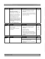
9.9
FaceScan ...................................................................................................... 285
9.9.1 Replacing the scan unit...................................................................... 285
9.9.1.1 Removing the defective scan unit .................................................... 285
9.9.1.2 Attaching new scan unit ................................................................... 287
9.9.1.3 What has to be done after replacing the scanner unit?.................... 294
9.9.2 Replacing the PoE module................................................................. 294
9.9.2.1 Removing the faulty PoE module ..................................................... 294
9.9.2.2 Installing the new PoE module......................................................... 296
9.10
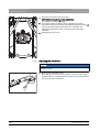
Head fixation device ...................................................................................... 298
9.10.1 Replacing receptacle element for head fixation (for unit with head
fixation device)
9.11
298
Light barriers ................................................................................................. 302
9.11.1 Replacing the light barriers ................................................................ 302
9.12
Boards ........................................................................................................... 302
9.12.1 Important notes about replacing boards............................................. 302
9.12.2 Replacing boards ............................................................................... 303
9.12.2.1Replacing PC board DX1 ................................................................. 304
9.12.2.2Replacing board DX11 ..................................................................... 305
9.12.2.3Replacing board DX32 ..................................................................... 305
9.12.2.4Replace board DX89........................................................................ 306
9.12.3 Measures following replacement of boards........................................ 306
9.12.3.1After changing the DX11 board........................................................ 310
9.12.3.2Replacing the tube assembly including board DX6.......................... 316
9.13
Cable............................................................................................................. 320
9.13.1 Replacing energy chain 1 completely ................................................ 320
9.13.2 Replacing cables................................................................................ 324
9.13.2.1Replacing fiber-optic cable L5, L6 or L15......................................... 324
9.13.2.2Cable replacement (L3, L5, L6, and L15)/Laying the cable/
corrugated tube at the rotation unit
325
9.13.2.3Replacing cable L7/L117 or L108 in cable track 2 ........................... 327
9.13.2.4Replacing cable L1 or grounding strap in cable track 1 ................... 330
10
64 26 345 D3437
D3437.076.03.02.02 04.2013
Sirona Dental Systems GmbH
10
11
12
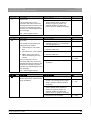
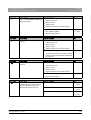
Maintenance ............................................................................................................
331
10.1
Calibrating the unit .......................................................................................
331
10.2
Checking the height adjustment ...................................................................
332
10.3
Checking the cables for damage..................................................................
333
10.4
Checking the tube data ................................................................................
333
10.4.1 Checking the tube voltage.................................................................
333
10.4.2 Checking the radiation time...............................................................
334
10.4.3 Checking the fan and temperature sensor ........................................
335
10.5
Checking the idling rollers ............................................................................
336
10.6
Checking the grounding straps.....................................................................
337
10.7
Checking the cable shields...........................................................................
338
10.8
Checking the protective ground wires ..........................................................
340
10.9
Checking the device leakage current ...........................................................
343
Dismantling and disposal.........................................................................................
345
11.1
Dismantling and reinstallation ......................................................................
345
11.2
Disposal........................................................................................................
345
Service Manual History............................................................................................
347
64 26 345 D3437
D3437.076.03.02.02
04.2013
11
båÖäáëÜ
Service Manual (as of February 2013) GALILEOS
Sirona Dental Systems GmbH
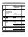
1 About this Service Manual
Service Manual (as of February 2013) GALILEOS
1
1.1 Scope
About this Service Manual
About this Service Manual
1.1 Scope
Scope of the Service Manual: GALILEOS, new
Scope
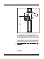
This Service Manual describes the service work for the digital volume
tomographs "GALILEOS Comfort", "GALILEOS ComfortPLUS", and
"GALILEOS Compact" for unit versions supplied as of February 2013. It
is intended for use exclusively by trained and authorized distributors and
service technicians.
1.2 Other documentation required
Other documentation required
In addition to this manual, you need the following documents:
ETL GALILEOS
båÖäáëÜ
Spare parts list
● GALILEOS List of Spare Parts: Order no. 61 25 699
GALILEOS wiring diagrams
Wiring diagrams
● GALILEOS Wiring References: Order no. 61 25 640
GALILEOS installation
Installation Instructions
● GALILEOS Installations Instructions: Order No. 61 25 574
● GALILEOS / ORTHOPHOS XG 3D Software installation: Order No.
61 42 389
● GALAXIS Operator's Manual: Order No. 61 23 488
● SIDEXIS XG Digital Radiography Installation Instructions:
Order no. 59 67 356
DVD text
You can order the technical documentation in paper form free of change
from our Customer Service Center by specifying the above mentioned
order numbers (REF).
You can also download the latest user documentation, such as
instructions for use, from the Sirona homepage (www.sirona.de HOME ⇨
Service ⇨ Technical Documentation).
1.3 Tools and auxiliary materials
Tools
Tools and
and auxiliary
auxiliary materials:
materials GALILEOS
● GALILEOS service set: Order No. 6146562
● Screwdriver set (slot and Phillips)
● Torx offset screwdrivers TX10, TX20, TX25
(included in the scope of supply)
● Hexagon socket-head screwdriver, hexagon socket-head screw size
6 mm
(included in the scope of supply)
● Open-end wrench, 13 mm A/F
● Socket wrench, 13 mm A/F, 17 mm A/F, 18 mm A/F
● Side cutting pliers
64 26 345 D3437
D3437.076.03.02.02
04.2013
11
1 About this Service Manual
Sirona Dental Systems GmbH
1.4 Structure of the document
Service Manual (as of February 2013) GALILEOS
● Spirit level
● Digital Multimeter, Accuracy Class 1
● Mult-O-Meter 512L
● Soldering tool for repairing cables
● Cable ties
● Teflon tape
● Loctite
1.4 Structure of the document
Structure of the document
1.4.1
Identification of the danger levels
Identification of the danger levels
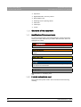
To prevent personal injury and material damage, please observe the
warning and safety instructions provided in this document, which are
highlighted as follows:
DANGER
Imminent danger that could result in serious bodily injury or death.
WARNING
Potentially dangerous situation that could result in serious bodily injury
or death.
CAUTION
Potentially dangerous situation that could result in slight bodily injury.
NOTICE
Potentially harmful situation which could lead to damage of the product
or an object in its environment.
IMPORTANT
Instructions for use and other important information.
Tip: Information for simplifying work.
1.4.2
Formats and symbols used
Formats and symbols used
The formats and symbols used in this document have the following
meaning:
12
64 26 345 D3437
D3437.076.03.02.02 04.2013
Sirona Dental Systems GmbH
1 About this Service Manual
Service Manual (as of February 2013) GALILEOS
1.4 Structure of the document
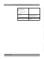
✔ Prerequisite
Requests you to do something.
1. First action step
2. Second action step
or
➢ Alternative action
Result
Identifies a reference to another
text passage and indicates the
relevant page number.
● List
Identifies a list item.
"Command / menu item"
Identifies commands / menu items
or a quote.
båÖäáëÜ
See “Formats and symbols
used [ → 12]”
64 26 345 D3437
D3437.076.03.02.02
04.2013
13
2 Safety instructions
Sirona Dental Systems GmbH
2.1 Modifications to the unit
Service Manual (as of February 2013) GALILEOS
2
Safety instructions
Safety instructions
2.1 Modifications to the unit
Modifications to the unit
Modifications to this unit which might affect the safety of the system
owner, patients or other persons are prohibited by law!
For reasons of product safety, this product may be operated only with
original Sirona accessories or third-party accessories expressly approved
by Sirona. The user is responsible for any damage resulting from the use
of non-approved accessories.
2.2 Fixed connection
Fixed connection
DANGER
Potentially lethal shock hazard!
Fixed connection!
Installing a mains plug instead of the specified fixed connection infringes
international medical regulatory actions and is prohibited. In case of
error, this puts patients, users, and other parties seriously at risk.
2.3 Electromagnetic compatibility
Electromagnetic compatibility
The unit complies with the requirements of standard IEC 60601-1-2.
Medical electrical equipment is subject to special EMC preventive
measures. It must be installed and operated as specified in the document
"Installation Requirements".
If high-voltage systems, radio link systems or MRI systems are located
within 5 m of the unit, please observe the specifications stated in the
installation requirements.
Portable and mobile RF communications equipment may interfere with
medical electrical equipment. Therefore, the use of mobile wireless
phones in medical office or hospital environments must be prohibited.
2.4 Electrostatic discharge
Electrostatic discharge (abbreviated: ESD – ElectroStatic Discharge)
Electrostatic discharge
Electrostatic discharge from people can damage electronic components
when the components are touched.
Touch a ground point to discharge static electricity before touching any
boards.
2.5 Switching the unit on
Safety
information
for switching on the unit: Service engineer
Switching
the unit on
Due to the risk of injury caused by malfunction, no person may be
positioned in the unit when it is switched on.
14
64 26 345 D3437
D3437.076.03.02.02 04.2013
Sirona Dental Systems GmbH
2 Safety instructions
Service Manual (as of February 2013) GALILEOS
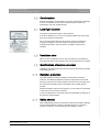
2.6 Condensation
2.6 Condensation
Safety information for condensation: Service engineer
Condensation
Extreme fluctuations of temperature may cause condensation inside the
unit. Do not switch the unit on before it has reached normal room
temperature. See also Technical Data.
2.7 Laser light localizer
Laser light localizer
Safety information for light localizer: Service engineer
The system incorporates Class 1 laser products.
A minimum distance of 10 cm (4") is required between the eye and the
laser. Do not stare into the beam.
båÖäáëÜ
Do not use the system with any other lasers, and do not make any
changes to settings or processes that are not described in these
operating instructions. This may lead to a dangerous exposure to
radiation.
2.8 Ventilation slots
Ventilation
Ventilation slots
slots
Never cover the ventilation slots on the unit under any circumstances,
since this may obstruct air circulation. This can cause the unit to overheat.
2.9 Qualifications of service personnel
Qualifications of service personnel
Installation and startup may be carried out only by personnel specifically
authorized by Sirona.
2.10 Radiation protection
Safety
information
for radiation protection: Service engineer
Radiation
protection
The valid radiation protection regulations and measures must be
observed. The statutory radiation protection equipment must be used.
During an exposure, the service engineer should move as far away from
the X-ray tube assembly as the coiled cable of the manual release
permits.
With the exception of the service engineer, no other persons are allowed
to stay in the room during an exposure.
In case of malfunctions, cancel the exposure immediately by letting go of
the exposure release button.
2.11 Safety checks
Safety
Safety checks
checks
After implementing repair work, protective conductors and device leakage
current checks must be carried out (see the sections on "Checking
protective conductor" and "Checking device leakage current").
64 26 345 D3437
D3437.076.03.02.02
04.2013
15
3 Unit description
Sirona Dental Systems GmbH
3.1 Unit classes and versions
Service Manual (as of February 2013) GALILEOS
3
Unit description
Unit description
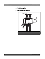
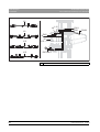
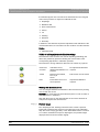
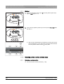
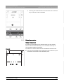
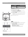
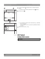
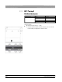
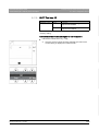
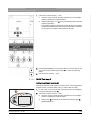
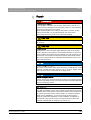
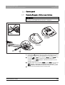
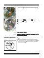
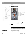
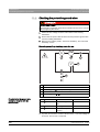
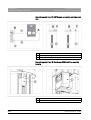
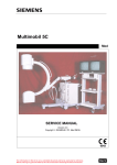
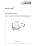
3.1 Unit classes and versions
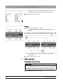
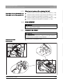
Unit classes and versions
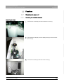
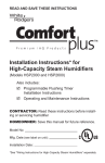
A
C
B
16
A
GALILEOS unit*
B
Control panel
C
FaceScan (optional)
64 26 345 D3437
D3437.076.03.02.02 04.2013
Sirona Dental Systems GmbH
3 Unit description
Service Manual (as of February 2013) GALILEOS
3.1.1
3.2 Hardware
Control panels
The "Comfort/ComfortPLUS" and "Compact" unit classes differ by the
equipment of the control panel (B). While the GALILEOS Comfort class
features a control panel with a color touchscreen (Easypad), the Compact
class is equipped with a simpler control panel with a single-line display
(Multipad). Due to their different control panels, the operating procedures
for these two system classes also vary.
båÖäáëÜ
Control panels
3.2 Hardware
Hardware
3.2.1
Information on the unit
Information on the unit
The following symbols are applied to the unit:
Accompanying documents
Accompanying documents
This symbol is affixed next to the unit rating plate.
Meaning: When operating the unit, observe the operating instructions.
This symbol is affixed on the unit rating plate.
Meaning: The accompanying documents are available on the homepage
of Sirona.
Electrostatic discharge (ESD)
Connector pins or sockets bearing ESD warning labels must not be
touched or interconnected without ESD protective measures. See also
"Electrostatic Discharge" and "Electromagnetic Compatibility" [ → 14].
64 26 345 D3437
D3437.076.03.02.02
04.2013
17
3 Unit description
Sirona Dental Systems GmbH
3.2 Hardware
Service Manual (as of February 2013) GALILEOS
Single use hygienic protective sleeves
Identification of single use devices
Prior to each exposure, the hygienic protective sleeves (single use
devices) must be fitted.
Single use devices are identified with the symbol shown on the left. They
must be disposed of immediately after use. Do not use single use devices
more than once.
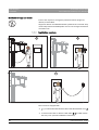
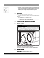
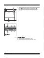
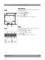
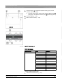
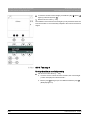
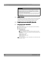
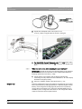
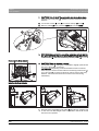
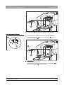
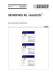
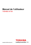
3.2.2
Installation versions
Installation versions
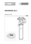
A
B
C
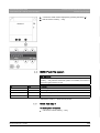
The unit can be equipped with...
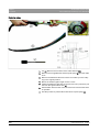
● a 1-3 m coiled cable with release button inside the treatment room (A)
or ...
● a remote control with or without coiled cable (B+C) located outside
the X-ray room (see also installation instructions).
18
64 26 345 D3437
D3437.076.03.02.02 04.2013
Sirona Dental Systems GmbH
3 Unit description
Service Manual (as of February 2013) GALILEOS
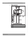
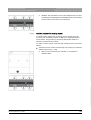
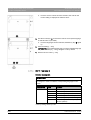
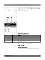
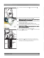
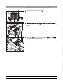
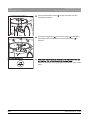
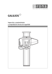
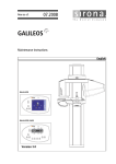
3.2.3
3.2 Hardware
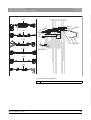
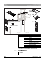
Modules and components
båÖäáëÜ
Modules
and components
components: GALILEOS
Modules and
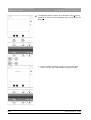
D
A
B
C
64 26 345 D3437
D3437.076.03.02.02
04.2013
A
Slide
B
Stand
C
Remote control [ → 21]
D
FACESCAN [ → 22] (optional)
19
3 Unit description
Sirona Dental Systems GmbH
3.2 Hardware
Service Manual (as of February 2013) GALILEOS
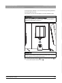
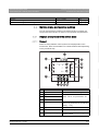
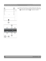
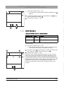
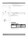
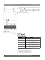
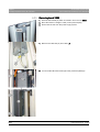
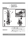
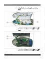
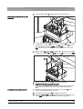
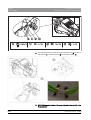
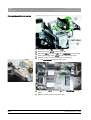
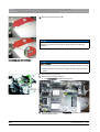
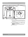
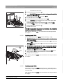
3.2.3.1
Slide
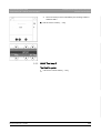
Slide
LS
MU
DX11
A
DX1
B
DX89
DX6*
LS*
DX7*
GALILEOS Comfort / Comfort PLUS
DX71*
GALILEOS Compact
Component
Designation
Function
Boards
DX1
Open loop/closed loop control in
general
DX11
Motor
Controller board
DX6*
(A)
Open loop/closed loop tube
assembly (GALILEOS Comfort/
Compact)
DX6*
(B)
Open loop/closed loop tube
assembly (GALILEOS
ComfortPLUS)
DX7*
Easypad touchscreen
(GALILEOS Comfort)
DX71*
LED display on Multipad
(GALILEOS Compact)
DX89
Image memory of the X-ray
detector
MU
Rotary movement of rotating
element
Light barriers LS
LS
Position control of the ring cycle
Position control of the swivel
arm
*) not available as individual repair part (see spare parts list).
20
64 26 345 D3437
D3437.076.03.02.02 04.2013
Sirona Dental Systems GmbH
3 Unit description
Service Manual (as of February 2013) GALILEOS
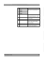
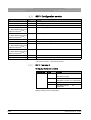
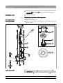
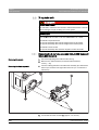
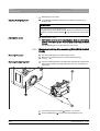
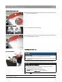
3.2.3.2
3.2 Hardware
Stand
Stand: GALILEOS, new
Stand
MHV
båÖäáëÜ
DX32
3.2.3.3
Component
Designation
Function
Boards
DX32
Power supply board
Motor
MHV
Linear movement of height
adjustment
Component
Designation
Function
Board
DX42
Display board for remote control
Remote control
Remote control
DX42
64 26 345 D3437
D3437.076.03.02.02
04.2013
21
3 Unit description
Sirona Dental Systems GmbH
3.2 Hardware
Service Manual (as of February 2013) GALILEOS
3.2.3.4
FaceScan
FaceScan
22
Component
Designation
Function
Boards
FACESCAN
Modular board
PoE
Power supply board
64 26 345 D3437
D3437.076.03.02.02 04.2013
Sirona Dental Systems GmbH
3 Unit description
Service Manual (as of February 2013) GALILEOS
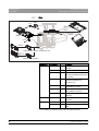
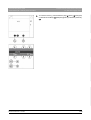
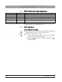
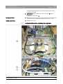
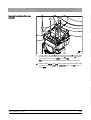
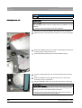
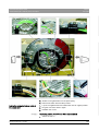
3.2.4
3.2 Hardware
Cabling overview
Cabling overview
L1
DX11
DX1
L5
L2
DX89
DX6
H1
L3
båÖäáëÜ
L3
L4
A
L4
DX32
L1
L2
L5
B
C
64 26 345 D3437
D3437.076.03.02.02
04.2013
A
Power switch
B
Line filter
C
Wago terminal
23
3 Unit description
Sirona Dental Systems GmbH
3.2 Hardware
Service Manual (as of February 2013) GALILEOS
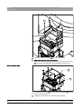
DX6 / J2 – J3
L6_XG
5922526
J307
DX1/
526
L6
5922
J306
L6 526 DX1/
5922
DX1 / J306 – J307
L6
L6
L9
L15
DX11
DX1
DX89
DX6
L9
H1
L10
L10
A
L15
DX7/DX71
A
24
Power switch
64 26 345 D3437
D3437.076.03.02.02 04.2013
Sirona Dental Systems GmbH
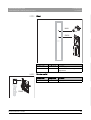
3 Unit description
Service Manual (as of February 2013) GALILEOS
3.2 Hardware
Cabling overview2: GALILEOS, new
L13
L19
L29
L16
DX11
DX1
DX89
LS
DX6
L16
HV
H1
L19
L27
L13 L27 L28*
båÖäáëÜ
A
DX7/DX71
L28*
L29
D
* Cable L28 cannot be replaced.
A
64 26 345 D3437
D3437.076.03.02.02
04.2013
Power switch
25
3 Unit description
Sirona Dental Systems GmbH
3.2 Hardware
Service Manual (as of February 2013) GALILEOS
L7
DX1
L108
L117
L25/L26
DX42
L108
L7
L117
E
L25
E
26
Media converter
64 26 345 D3437
D3437.076.03.02.02 04.2013
Sirona Dental Systems GmbH
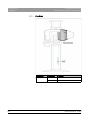
3 Unit description
Service Manual (as of February 2013) GALILEOS
3.2 Hardware
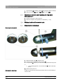
FaceScan cabling overview
FaceScan cabling
L77 L78
DX11
DX1 DX89
L77
FACESCAN
båÖäáëÜ
A
L77
L78
PoE
A
64 26 345 D3437
D3437.076.03.02.02
04.2013
Power switch
27
3 Unit description
Sirona Dental Systems GmbH
3.2 Hardware
Service Manual (as of February 2013) GALILEOS
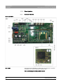
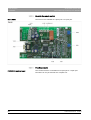
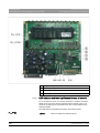
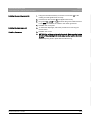
3.2.5
Board photos
Board photos
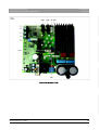
3.2.5.1
Boards DX1/DX11
Board DX6
Boards in the slide
Boards in the slide
DX6: GALILEOS, new
This board is not available as a spare part or a repair part. X-ray tube
assemblies can only be ordered as complete units.
GALILEOS Compact and GALILEOS Comfort:
28
64 26 345 D3437
D3437.076.03.02.02 04.2013
Sirona Dental Systems GmbH
3 Unit description
3.2 Hardware
båÖäáëÜ
Service Manual (as of February 2013) GALILEOS
GALILEOS Comfort PLUS:
64 26 345 D3437
D3437.076.03.02.02
04.2013
29
3 Unit description
Sirona Dental Systems GmbH
3.2 Hardware
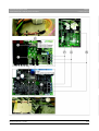
Board DX7
Service Manual (as of February 2013) GALILEOS
DX7: Restriction for GALILEOS, new
This board is only used in the "GALILEOS Comfort" and the "GALILEOS
ComfortPLUS" (not in the "GALILEOS Compact").
The board is not available as a spare part or a repair part. The Easypad
can only be ordered as a complete unit.
30
64 26 345 D3437
D3437.076.03.02.02 04.2013
Sirona Dental Systems GmbH
3 Unit description
3.2 Hardware
båÖäáëÜ
Service Manual (as of February 2013) GALILEOS
DX71 GALILEOS / XG 3 / XG 5
Board DX71
64 26 345 D3437
D3437.076.03.02.02
DX71: Restriction for GALILEOS, new
This board is only used in the "GALILEOS Compact" (not in the
"GALILEOS Comfort" or the "GALILEOS ComfortPLUS").
04.2013
31
3 Unit description
3.2 Hardware
32
Sirona Dental Systems GmbH
Service Manual (as of February 2013) GALILEOS
64 26 345 D3437
D3437.076.03.02.02 04.2013
Sirona Dental Systems GmbH
3 Unit description
Service Manual (as of February 2013) GALILEOS
3.2 Hardware
DX89: GALILEOS
båÖäáëÜ
Board DX89
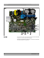
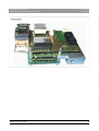
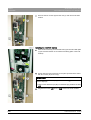
3.2.5.2
Boards in the stand
Boards in the stand
Board DX32
A
64 26 345 D3437
D3437.076.03.02.02
04.2013
Line filter
33
3 Unit description
Sirona Dental Systems GmbH
3.2 Hardware
Service Manual (as of February 2013) GALILEOS
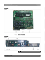
3.2.5.3
Board in the remote control
Board in the remote control
Board DX42
This board is not available as a spare part or a repair part.
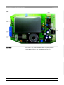
3.2.5.4
FaceScan boards
FaceScan boards
FACESCAN modular board
34
This modular board is not available as a spare part or a repair part.
FaceScan can only be ordered as a complete unit.
64 26 345 D3437
D3437.076.03.02.02 04.2013
Sirona Dental Systems GmbH
3 Unit description
3.2 Hardware
båÖäáëÜ
Service Manual (as of February 2013) GALILEOS
64 26 345 D3437
D3437.076.03.02.02
04.2013
35
3 Unit description
Sirona Dental Systems GmbH
3.2 Hardware
Service Manual (as of February 2013) GALILEOS
PoE power supply board
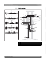
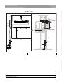
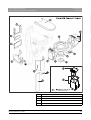
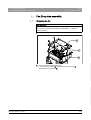
3.2.6
Covers
Covers
When removing covers, always remember that direct sunlight or bright
room lighting can cause system malfunctions due to activated light
barriers. Therefore: avoid direct sunlight and bright room lighting above
the unit!
Reattach all covers. When attaching the covers: be sure to screw the
sheet metal cover back on.
IMPORTANT: For reasons of electromagnetic compatibility, be sure to
fasten all screws.
GALILEOS
Covers: GALILEOS, new
IMPORTANT
The covers of your unit may differ slightly from those shown in the
following illustration, depending on the unit class/unit serial number.
36
64 26 345 D3437
D3437.076.03.02.02 04.2013
Sirona Dental Systems GmbH
3 Unit description
3.2 Hardware
båÖäáëÜ
Service Manual (as of February 2013) GALILEOS
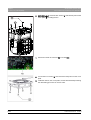
A
64 26 345 D3437
D3437.076.03.02.02
04.2013
Profile covers, top and bottom
B
Intermediate piece
C
Tube assembly cover, rear
P
Tube assembly cover
E
Cover for ring center (in units without head fixation device)
37
3 Unit description
Sirona Dental Systems GmbH
3.2 Hardware
Service Manual (as of February 2013) GALILEOS
3.2.7
F
Acquisition unit for head fixation device (in units with head
fixation device)
G
Ring cover
H
Support cover
I
Swivel arm cover
J
Arm cover
K
Slide cover, front
L
Slide cover, top rear
A
Slide cover, center rear
N
Slide cover, bottom rear
O
X-ray detector cover
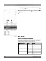
Technical data
Technical data
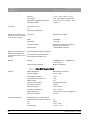
3.2.7.1
Chassis:
X-ray tube assembly:
Detector:
38
GALILEOS Compact/GALILEOS Comfort
GALILEOS Compact/GALILEOS Comfort
Model designation
GALILEOS Compact/Comfort
Nominal voltage:
200 V – 240 V
Permissible fluctuation:
±10%
Permissible drop under load:
10%
Rated current:
6A
Nominal power output:
0.6 kW at 85 kV/7mA
Current time product:
42 mAs
Nominal frequency:
50 Hz / 60 Hz
Internal line impedance:
max. 0.8 ohms
Main building fuse:
25 A slow-blow (16 A for single line)
Power consumption:
0.9 kVA
Focal spot size acc. to IEC 60336,
measured in the central X-ray beam:
0.5
kV:
85 kV
mA:
5 mA / 7 mA
Pulsed mode:
10 ms – 30 ms
Total filtration of X-ray tube assembly
> 2.5 Al / 90 IEC 60522
Integrated filter:
0.4 mm Cu
Cone-beam angle:
collimated to approx. 24°
High voltage generation frequency:
80 kHz – 100 kHz
Type:
Image intensifier (I.I.),
Thales or Siemens
Active input window size:
215 mm (8 1/2") diameter
Camera:
Pixels: 10002
64 26 345 D3437
D3437.076.03.02.02 04.2013
Sirona Dental Systems GmbH
3 Unit description
Service Manual (as of February 2013) GALILEOS
3.2 Hardware
FPS: 15 – 30
Dynamics: 12 bits,
(4096 brightness values), 60 dB
Scanning process:
Source-I.I. converter coating distance
(central X-ray beam)
510 mm (20 1/16")
Source-isocenter distance
(central X-ray beam)
333 mm (13 1/8")
Source-skin distance
(minimum distance)
approx. 220 mm (8 5/8")
Orbital angle
204°
Scan time
approx. 14 s
Number of single exposures
200
båÖäáëÜ
Geometry:
Reconstruction:
Marking of focal spot:
Automatic exposure blocking:
Class I device
Degree of protection against electric
shock:
The duration of automatic exposure
blocking (cooling period) depends on the
set kV/mA level and the actual exposure
time. Depending on the tube load, interval
times of 8 s to 300 s are automatically set
by the system.
Type B device
Degree of protection against ingress of Ordinary equipment
water:
(without protection against ingress of
water)
Year of manufacture:
(on the rating plate)
Operating mode:
Continuous operation
Long-term power output:
100 W
Anode material:
Tungsten
Exposure parameters for determining
leakage radiation:
7mA / 85 kV
Continuing current for leakage radiation 0.14 mA
measurements:
Transport and storage temperature:
Basic unit
64 26 345 D3437
D3437.076.03.02.02
04.2013
-40°C – +70°C (-40°F – 158°F)
39
3 Unit description
Sirona Dental Systems GmbH
3.2 Hardware
Service Manual (as of February 2013) GALILEOS
Detector
-30°C – +55°C (-22°F – 131°F)
Air humidity:
10% – 95% without condensation
Admissible operating temperature:
from +10°C to +35°C (50°F – 95°F)
Operating altitude:
≤ 3000 m
X-ray tube:
Toshiba DF-151R
or
Siemens SR 120/15/60
Minimum requirements for
reconstruction PC (included
in the scope of supply):
Processor:
DualCore from 2 GHz
RAM:
4 GB RAM
Hard disks:
> 500 GB
Operating system:
Windows XP Professional SP3 or
Windows 7 Professional
External drive:
1x DVD-ROM, dual-layer
Minimum requirements for
See SIDEXIS XG Operator’s Manual.
SIDEXIS visualization PC
The system requirements are also
(not included in the scope of
listed under www.sidexis.com
supply):
Network:
Network:
100 MB Ethernet, 1 Gbit Ethernet
recommended
Communication interface:
RJ45 for LAN cable
3.2.7.2
Chassis:
X-ray tube assembly:
40
GALILEOS Comfort PLUS
GALILEOS Comfort PLUS
Model designation
GALILEOS ComfortPLUS
Nominal voltage:
200 V – 240 V
Permissible fluctuation:
±10%
Permissible drop under load:
10%
Rated current:
6A
Nominal power output:
0.6 kW at 98 kV/6mA
Current time product:
30 mAs
Nominal frequency:
50 Hz / 60 Hz
Internal line impedance:
max. 0.8 ohms
Main building fuse:
25 A slow-blow (16 A for single line)
Power consumption:
0.9 kVA
Focal spot size acc. to IEC 60336,
measured in the central X-ray beam:
0.5
kV:
98 kV
mA:
3 mA - 6 mA
Pulsed mode:
10 ms – 14 ms
64 26 345 D3437
D3437.076.03.02.02 04.2013
Sirona Dental Systems GmbH
3 Unit description
Service Manual (as of February 2013) GALILEOS
Detector:
3.2 Hardware
min. permanent filtering:
min. half-value layer:
2.8 mm Al / 98 IEC 60522
3.9 mm Al
Integrated filter:
0.2 mm Cu
Cone-beam angle:
collimated to approx. 24°
High voltage generation frequency:
80 kHz – 100 kHz
Type:
Image intensifier (I.I.), Siemens
Active input window size:
215 mm (8 1/2") diameter
Camera:
Pixels: 10002
FPS: 15 – 30
Geometry:
Scanning process:
Source-I.I. converter coating distance
(central X-ray beam)
590 mm (23 1/4")
Source-isocenter distance
(central X-ray beam)
413 mm (16 1/4")
Source-skin distance
(minimum distance)
approx. 300 mm (11 13/16")
Orbital angle
204°
Scan time
approx. 14 s
Number of single exposures
200
HD mode 357
båÖäáëÜ
Dynamics: 12 bits,
(4096 brightness values), 63 dB
Reconstruction:
Marking of focal spot:
Automatic exposure blocking:
Class I device
Degree of protection against electric
shock:
The duration of automatic exposure
blocking (cooling period) depends on the
set kV/mA level and the actual exposure
time. Depending on the tube load, interval
times of 8 s to 300 s are automatically set
by the system.
Type B device
Degree of protection against ingress of Ordinary equipment
water:
(without protection against ingress of
water)
64 26 345 D3437
D3437.076.03.02.02
04.2013
41
3 Unit description
Sirona Dental Systems GmbH
3.2 Hardware
Service Manual (as of February 2013) GALILEOS
Year of manufacture:
(on the rating plate)
Operating mode:
Continuous operation
Long-term power output:
100 W
Anode material:
Tungsten
Exposure parameters for determining
leakage radiation:
6mA / 98 kV
Continuing current for leakage radiation 0.14 mA
measurements:
Transport and storage temperature:
Basic unit
-40°C – +70°C (-40°F – 158°F)
Detector
-30°C – +55°C (-22°F – 131°F)
Air humidity:
10% – 95% without condensation
Admissible operating temperature:
between +10°C and +35°C
(50°F – 95°F)
At a room temperature of > 35°C (> 95°F),
Sirona recommends using an air
conditioning system.
Operating altitude:
≤ 3000 m
X-ray tube:
Siemens SR 120/15/60
Minimum requirements for
reconstruction PC (included
in the scope of supply):
Processor:
QuadCore Intel i5
RAM:
8 GB RAM
Hard disks:
1 TByte
Operating system:
Windows 7 64-bit (mandatory)
External drive:
1x DVD-ROM, dual-layer
Graphics card:
explicit (not onboard),
at least 1 GB RAM
Minimum requirements for
See SIDEXIS XG Operator’s Manual.
SIDEXIS visualization PC
The system requirements are also
(not included in the scope of
listed under www.sidexis.com
supply):
Network:
42
Network:
100 MB Ethernet, 1 Gbit Ethernet
recommended
Communication interface:
RJ45 for LAN cable
64 26 345 D3437
D3437.076.03.02.02 04.2013
Sirona Dental Systems GmbH
3 Unit description
Service Manual (as of February 2013) GALILEOS
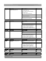
3.3 Software/compatibility
3.3 Software/compatibility
Software/compatibility
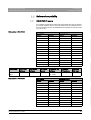
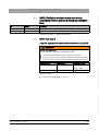
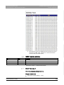
3.3.1
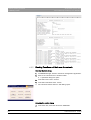
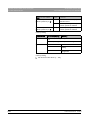
GALILEOS firmware
GALILEOS firmware
Any software combinations other than those listed here are not allowed.
If a module software version does not match the main software version,
the main software version is identified with an asterisk on the info screen
(e.g. 04.12.00*).
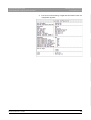
GALILEOS
Remote control
Board
Software
Board
Software
DX6
03.07.04
DX42
02.56.04
DX6NG
04.09.00
DX7
02.80.07
DX7-L0
02.29.00
DX7-L1
02.29.00
DX7-L2
02.27.00
DX7-L3
02.27.00
DX7-L4
02.04.00
DX7-L5
02.02.00
DX71
02.54.03
DX11
04.12.00
DX11-FPGA
01.04.00
DX89
01.59.02
DX89 FPGA
01.58.00
båÖäáëÜ
Main software V04.12.00
SIDEXIS XG
GALILEOS
software
RCU server
software
GALILEOS
Implant
FaceScan unit
software
FaceScan
PC software
FaceScan
USB stick
V2.5.6 or
higher
V2.0
V2.3
V1.9SP1
V1.15.369–
V1.14369
V1.2
FS0004
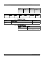
Main software V04.14.00
64 26 345 D3437
D3437.076.03.02.02
04.2013
GALILEOS
Remote control
Board
Software
Board
Software
DX6
03.08.00
DX42
02.58.02
DX6NG
04.09.07
DX7
02.82.01
DX7-L0
02.31.00
DX7-L1
02.31.00
DX7-L2
02.29.00
DX7-L3
02.29.00
DX7-L4
02.06.00
DX7-L5
02.02.00
DX71
02.55.02
DX11
04.14.00
43
3 Unit description
Sirona Dental Systems GmbH
3.3 Software/compatibility
Service Manual (as of February 2013) GALILEOS
GALILEOS
Remote control
Board
Software
DX11-FPGA
01.04.00
DX89
01.60.02
DX89 FPGA
01.58.00
Board
Software
SIDEXIS XG
GALILEOS
software
RCU server
software
GALILEOS
Implant
FaceScan unit
software
FaceScan
PC software
FaceScan
USB stick
V2.5.6 or
higher
V2.1
V2.4
V1.9 SP1
V1.15.369 –
V1.14369
V1.2
FS0004
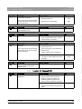
3.3.2
FaceScan firmware
FaceScan firmware
FaceScan
GALILEOS
main unit software
FS 0004
or higher
V04.12.00 or higher
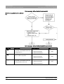
3.3.3
SIDEXIS XG
V2.0 or higher
V2.5.6 or higher
GALILEOS Software
GALILEOS
software versions: GALILEOS, new
GALILEOS Software
44
GALILEOS Software
GALILEOS
Software
CD index
Remarks
V2.0
006
Requires main unit software V 04.12.00
or higher and SIDEXIS 2.5.6 or higher.
64 26 345 D3437
D3437.076.03.02.02 04.2013
Sirona Dental Systems GmbH
4 General operating procedures
Service Manual (as of February 2013) GALILEOS
4
4.1 Switching the unit on
General operating procedures
General operating procedures
4.1 Switching the unit on
Switching the unit on
WARNING
X-rays
Be sure to observe the radiation protection regulations applicable in
your country.
➢ No person may be positioned in the unit when it is switched on.
NOTICE
Check the room height before you raise the unit.
➢ If the room height is less than 2.27 m (89 3/8") or 2.30 m (90 1/2")
for installation with the floor stand, you must limit the maximum
travel height [ → 232].
NOTICE
Fluctuations in temperature can cause condensation to form in the unit.
Electrical components are destroyed by short circuits.
➢ Do not switch the unit on until the temperature of the unit has
adapted to the ambient temperature and the condensation has
evaporated.
Waiting time when switching on and off
NOTICE
The unit must not be switched on/off constantly.
Constant switching on and off reduces the service life of individual unit
components and results in increased power consumption.
➢ After switching the unit off, wait for approx. 60 seconds before
switching it on again.
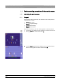
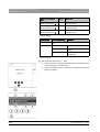
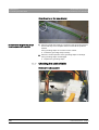
4.1.1
Switching the "GALILEOS Comfort / Comfort PLUS" on
Switching the "GALILEOS Comfort / Comfort PLUS" on
NOTICE
The surface of the touchscreen is sensitive.
The touchscreen can be damaged or its surface scratched.
➢ Never use pointed objects such as ballpoint pens, pencils, etc. to
operate the touchscreen.
➢ Only use your fingertips to operate the touchscreen.
64 26 345 D3437
D3437.076.03.02.02
04.2013
45
båÖäáëÜ
Damage to the unit
4 General operating procedures
Sirona Dental Systems GmbH
4.1 Switching the unit on
Service Manual (as of February 2013) GALILEOS
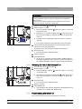
IMPORTANT
After the unit is switched on, the touchscreen has only limited readability
for several minutes until the background lighting has completed its
warm-up phase.
After the unit is switched off with the main switch, the touchscreen
remains lit for approx. another 3 to 5 seconds.
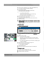
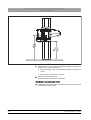
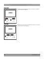
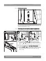
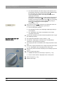
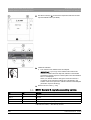
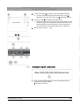
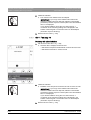
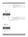
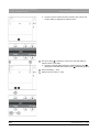
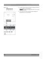
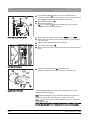
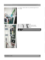
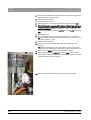
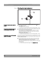
1. Turn the main switch (A) to position I.
2. Wait for approx. 1 minute.
A
The X-ray radiation indicator (B) lights up for approx. 1 second as
a functional check.
B
After approx. 2 seconds, the green LED (C) in the upper part of
the control panel lights up. This LED remains lit as long as the
unit is on.
C
The start screen is displayed on the touchscreen for several
seconds.
The program selection is then displayed on the touchscreen.
3. Check whether the patient symbols on the touchscreen can be
selected in exactly the right position.
If problems occur during selection, adjust the touchscreen.
4. Press the R key.
The unit moves to its starting position.
5. Switch on the PC.
6. Start SIDEXIS XG.
As long as no connection has been made to SIDEXIS XG, the
message is displayed in the comment line of the control panel on
the "Switch SIDEXIS to ready for exposure state" touchscreen.
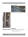
4.1.2
Switching the "GALILEOS Compact" on
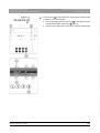
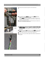
1. Turn the main switch (A) to position I.
Switching the "GALILEOS Compact" on
2. Wait for approx. 1 minute.
A
The X-ray radiation indicator (B) lights up for approx. 1 second as
a functional check.
B
After approx. 2 seconds, the green LED (C) in the upper part of
the control panel lights up. This LED remains lit as long as the
unit is on.
C
3. Press the R key.
The unit moves to its starting position.
4. Switch on the PC.
5. Start SIDEXIS XG.
Help message H401 remains displayed on the Multipad as long
as there is no connection with SIDEXIS XG.
4.1.3
Factory setting after switch-on
Factory
setting after
after switch-on:
Factory setting
switch-on GALILEOS
The unit has the following factory configuration on delivery:
46
64 26 345 D3437
D3437.076.03.02.02 04.2013
Sirona Dental Systems GmbH
4 General operating procedures
Service Manual (as of February 2013) GALILEOS
4.2 Updating the firmware
● Start settings:
–
Starting position: from the front (right)
–
VO4 (for "GALILEOS Compact")
–
VO1 (for "GALILEOS Comfort")
–
VO5 (for "GALILEOS ComfortPLUS")
–
Patient symbol 2: 85 kV/21mAs
● The acoustic signal for end of exposure is activated.
Only for "GALILEOS Comfort" and "GALILEOS ComfortPLUS":
● The unit language is preconfigured as ordered.
● The welcome screen is switched on.
● For GALILEOS ComfortPLUS: HD mode is enabled.
If the customer requires a different configuration, this can be implemented
via service routine S017.
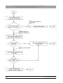
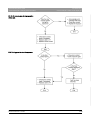
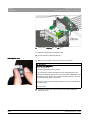
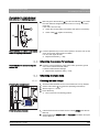
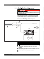
4.2 Updating the firmware
Updating the firmware
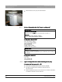
4.2.1
Updating the unit firmware
Updating the unit firmware
IMPORTANT
Downgrading to older versions
Downgrading the unit software version V04.14.00 or higher to an older
version is not a simple process. However, if this is essential, please get
in contact with the SIRONA Customer Service Center (CSC) in
advance.
Software update for GALILEOS, new
IMPORTANT
For GALILEOS Compact / Comfort:
For a firmware update to the device from version V03.07.02 or lower to
version V04.14.00 or higher, an intermediate update to version
V04.07.00 must be performed first.
Also read the information provided on the firmware CD supplied with the
unit and on the SIRONA dealer page on the Internet very carefully. These
sources always contain the latest information on software updates.
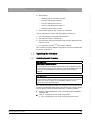
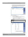
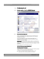
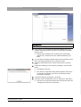
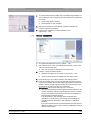
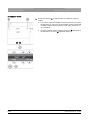
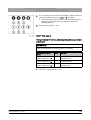
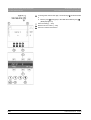
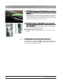
1. Start the "SIDEXIS Manager" under "Start"/"Programs"/"SIDEXIS"/
"SIDEXIS XG".
2. Click on "Configuration of the X-ray components".
The "Configuration of the X-ray components" menu opens.
64 26 345 D3437
D3437.076.03.02.02
04.2013
47
båÖäáëÜ
● The first name, last name and date of birth lines are displayed on the
welcome screen.
4 General operating procedures
4.2 Updating the firmware
Sirona Dental Systems GmbH
Service Manual (as of February 2013) GALILEOS
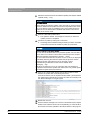
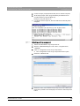
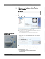
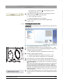
3. Select the "Attributes" tab.
4. Click the "Software update" button.
The dialog box for entering the service password opens.
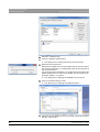
5. Enter the service password.
Enter the first 4 digits of the current system date in reverse order as
the service password (e.g. on 05/24/1995, 5042 must be entered as
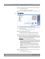
the service password.
If an incorrect service password or no password at all is entered, the
limited update menu for users will be started. This only supports an
automatic update [ → 51] option.
The dialog box for selecting the installation source opens.
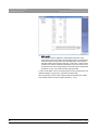
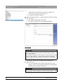
6. Click on the button with the 3 dots.
The dialog box for selecting the update file opens.
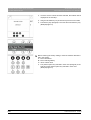
7. Select the desired update file from the list and confirm the selection
with the "Open" button.
48
64 26 345 D3437
D3437.076.03.02.02 04.2013
Sirona Dental Systems GmbH
4 General operating procedures
Service Manual (as of February 2013) GALILEOS
4.2 Updating the firmware
båÖäáëÜ
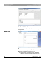
The update file is located on the unit software CD. It is delivered with
each DX11 replacement board and also included in the country set.
The contents of the CD can be downloaded from the Dealer domain
of the SIRONA Internet home page (under Products/Imaging
systems): www.sirona.com
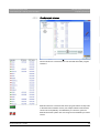
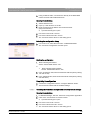
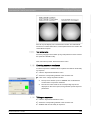
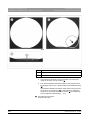
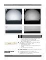
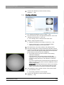
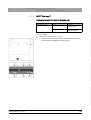
8. Click the "Next" button.
The software manager opens.
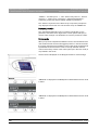
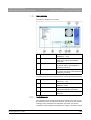
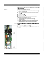
The action window (A) of the software manager displays the
modules and their current software versions.
In the structure tree on the left (B) of the software manager, the
update modes "Automatic" and "Main version" can now be
selected.
IMPORTANT
For historical reasons, two versions of module DX6 appear in the action
window (A) of the software manager. The installed version is indicated
by a green bar.
64 26 345 D3437
D3437.076.03.02.02
04.2013
49
4 General operating procedures
Sirona Dental Systems GmbH
4.2 Updating the firmware
Service Manual (as of February 2013) GALILEOS
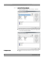
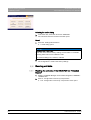
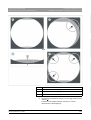
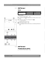
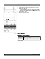
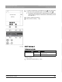
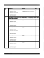
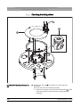
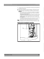
9. Select the desired mode for the software update (see chapter entitled
"Update mode [ → 51]").
NOTICE
Unit inoperability!
Before starting the software update, make sure that no unit movements
are active. Otherwise the system may become inoperable in rare cases.
The X-ray detector must be installed as part of the update. Exposure
readiness must be deselected in SIDEXIS XG and the unit must not
already be in service mode.
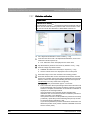
10. Click the "Start SW update" button.
The update is started. A message box informs you when the
update process is completed.
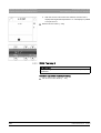
11. Confirm the update by clicking the "OK" button.
A message in the software manager notifies you that a unit restart
is required to activate the software update you performed.
NOTICE
Effectiveness of the software update
The unit must be restarted after every software update. The new DX11
version will not run until the unit has been rebooted (see also chapter
"Measures following replacement of boards [ → 306]").
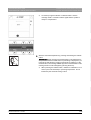
Any errors with the consecutive numbers 01, 03, 04, 06 or 07 displayed
immediately following the software update may be ignored. If these
messages appear again after the unit is rebooted, perform
troubleshooting as described in the section entitled "Error
messages [ → 79]".
If anything conspicuous occurs in connection with unit handling on
completion of the software update and restart of the unit, please repeat
the software update as the first measure.
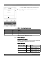
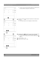
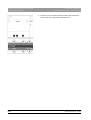
12. Click on the "Show logfile" button and use the log files to check
whether the update was successfully performed.
If it features entries such as "Update of DXxx failed!", please perform
the update again. Repeat this procedure as often as necessary until
the "failed messages" no longer appear.
13. Restart the unit now.
14. Use the software manager or the service routine S008.2 (see chapter
entitled "Unit software versions and compatibility") to check whether
all modules have been updated to the latest release of the program
50
64 26 345 D3437
D3437.076.03.02.02 04.2013
Sirona Dental Systems GmbH
4 General operating procedures
Service Manual (as of February 2013) GALILEOS
4.2 Updating the firmware
(see chapter entitled "Check program releases [ → 53]".
15. Call up "Further Details".
This generates an XML file (with the system parameters) which is
Filed in the PDATA/.../P2K_Config directory under the network name
of the unit.
4.2.1.1
Update mode
Update
Update mode:
mode GALILEOS, new
IMPORTANT
Update mode Module update is only intended for internal Sirona
purposes and is not activated for User or Service mode.
båÖäáëÜ
In Service mode (accessible only by entering the Service
Password [ → 148]), the update manager supports two modes for
updating the software; these can be selected via the elements
"Automatic" and "Main version" in the structure tree:
● Automatic
The software of all components is automatically updated to the latest
software version.
The right window displays a list of the modules, their installed
software version and the latest software version offered by the
update.
64 26 345 D3437
D3437.076.03.02.02
04.2013
51
4 General operating procedures
4.2 Updating the firmware
Sirona Dental Systems GmbH
Service Manual (as of February 2013) GALILEOS
● Main version
The software can be updated or downgraded using this menu.
This update mode is required, among other things, if a replacement
module arrives from the warehouse and features a newer release
than the existing main release of the unit. In this case, a main version
update to the overall unit status (displayed on the info screen) must
be performed for the corresponding component with the appropriate
update file (*.SUI). The module is then reprogrammed.
In User mode (which can be accessed without a service password), the
update manager only supports "Automatic" update mode.
The colored bars in front of the software releases indicate their validity
(see chapter entitled "Check program releases [ → 53]").
52
64 26 345 D3437
D3437.076.03.02.02 04.2013
Sirona Dental Systems GmbH
4 General operating procedures
Service Manual (as of February 2013) GALILEOS
4.2.1.2
4.2 Updating the firmware
Check program releases
båÖäáëÜ
Check
Check program
program releases:
releases GALILEOS, new
You can use the action window (A) of the software manager to check
which modules are connected to the unit and what their latest program
release is.
Modules which are connected and whose program release corresponds
to the latest main software version (see chapter entitled "Unit software
versions and compatibility" are identified by a continuous green bar.
Modules which the system does not recognize are identified by a broken
red bar.
64 26 345 D3437
D3437.076.03.02.02
04.2013
53
4 General operating procedures
Sirona Dental Systems GmbH
4.2 Updating the firmware
Service Manual (as of February 2013) GALILEOS
If the actual status of the module cannot be polled for the update, the
actual SW version will be displayed as = V00:00.
If a module has a hardware incompatibility to the program status to be
programmed or the software version on the module is newer than the one
in the update file, this will be indicated by a red triangle with an
exclamation mark.
If the version of the selected update file is lower than the current software
version of the unit, then there will be no display in the right window. The
downgrade required in this case is possible only via "Main version" mode.
4.2.2
Updating the FaceScan firmware
Updating the FaceScan firmware
There are two ways of updating the FaceScan firmware:
● Option 1: Update via USB stick [ → 54]
The program data on the FaceScan unit is completely overwritten.
● Option 2: Update via the network [ → 56]
The program data is transferred to the FaceScan unit. Unlike in option
1, the unit configuration data is, however, not overwritten.
4.2.2.1
Option 1: Update using the FaceScan USB stick
Option 1: Update using the FaceScan USB stick
Opening FaceScan
1. Unscrew the cover (A) from the FaceScan.
2. Pull gray cable L78.4 from slot X2 of the FACESCAN modular board.
3. Unscrew the protective plate (T) from the FaceScan unit.
The FACESCAN modular board is visible.
4. Plug cable L78.4 again into slot X2 on the FACESCAN modular
board.
Updating the software
1. Plug the FaceScan USB stick into the PC.
2. Open the "facescan_settings.cfg" configuration file in a text editor.
54
64 26 345 D3437
D3437.076.03.02.02 04.2013
Sirona Dental Systems GmbH
4 General operating procedures
Service Manual (as of February 2013) GALILEOS
4.2 Updating the firmware
3. Enter the value "UPDATE" for the "USB_STICK_MODE" entry
(for example: USB_STICK_MODE=UPDATE).
4. For selection by DHCP:
Enter the value "ON" for the "DCHP_STATE" entry
(for example: DHCP_STATE=ON).
or
➢
For selection without DHCP:
Enter the value "OFF" for the "DCHP_STATE" entry
(for example: DHCP_STATE=OFF).
5. Enter the value "OFF" for the "DCHP_STATE" entry
(for example: DHCP_STATE=OFF).
6. Specify the IP address and the subnet mask in the "IP" and
"Netmask" entries.
8. NOTICE! Incorrect removal of the USB stick can lead to loss of data
on the USB stick.
Remove the USB stick using the Safely Remove function (operating
system) of the PC.
Starting the update
✔ The unit must be switched off.
NOTICE
Always switch the device off before inserting the USB stick.
Before the FaceScan USB stick can be inserted into the USB socket of
the FACESCAN modular board, GALILEOS must be switched off.
Otherwise the update will not be completed. Instead, the configuration
data stored on the USB stick will be uploaded to GALILEOS.
1. Insert the USB stick into the USB port (U) of the FACESCAN modular
board.
2. Switch the unit on again.
The FaceScan will be updated.
Both LEDs in the status display light up during the update.
The process takes around 5 minutes (around 1 minute in the
event of an error).
The "USB_STICK_MODE" entry in the facescan_settings.cfg file
is reset to "CONFIG".
3. Wait until the green status display LED goes out.
The blue LED should then light up.
The update is completed.
4. Switch GALILEOS off.
5. Remove the FaceScan USB stick safely from the USB port.
Checking the update
1. Plug the FaceScan USB stick into a PC.
2. Open the "facescan_settings.log" log file in a text editor.
3. Check the entries in the log file.
64 26 345 D3437
D3437.076.03.02.02
04.2013
55
båÖäáëÜ
7. Save your changes.
4 General operating procedures
Sirona Dental Systems GmbH
4.2 Updating the firmware
Service Manual (as of February 2013) GALILEOS
If the update was successful, the log file should state:
"Facescan device software updated with version … successful!"
4. Remove the USB stick from the PC.
Closing the FACESCAN USB slot
Closing FaceScan
1. Pull cable L78(L74) from the X2 socket of the FACESCAN modular
board.
2. Screw the protective plate (T) onto the FaceScan unit.
3. Plug cable L78(L74) into the X2 socket on the FACESCAN modular
board.
4. Screw down the cover (A) onto the FaceScan.
Concluding the update
1. Switch the unit on.
2. Perform a complete unit calibration [ → 145].
3. Perform a white balance [ → 168].
4.2.2.2
Option 2: Firmware update via the network
Option 2: Firmware update via the network
Opening the web dialog
1. In SIDEXIS Manager, start the "Facescan Configuration" application.
2. Click on the "Facescanner in browser" button.
A password dialog box opens.
3. In the field "User" enter "service".
56
64 26 345 D3437
D3437.076.03.02.02 04.2013
Sirona Dental Systems GmbH
4 General operating procedures
Service Manual (as of February 2013) GALILEOS
4.2 Updating the firmware
4. In the field "Password" enter "sirona".
The "Facescan Device Service " web dialog opens.
Select Update dialog
Select Update dialog
1. In the menu bar, select the menu item "UPDATE".
The "Facescan Firmware Update" window opens.
2. Press the "Enter Update Menu" button.
The unit restarts in update mode with the message "System
rebooting... Please, wait until both status leds are on and press
'Go to Update Menu'". The process takes a few minutes.
3. When both LEDs light up, press the "Go to Update Menu" button.
Starting the update
2. Navigate to the firmware update file and select it.
3. Press the "Upload Image" button.
The upload runs in the background and can take up to 10 mins.
The upload ends with the message "Update successfully done!".
4. Press the "Run Update" button.
The update starts.
The update ends automatically after around 5 minutes with the
message "Update successfully done!".
5. Press the "Reboot" button.
The message "Device rebooting. Service menu will be
accessible in several minutes." appears.
The unit is restarted.
6. Wait around a minute until the green LED on the FaceScan unit
begins to light up.
7. Only if the SIRONA browser is not being used:
Refresh the browser display (e.g. in Windows® Internet Explorer:
press [F5]).
The update is completed.
Concluding the update
1. Only at initial installation: Perform a complete unit calibration [ → 145].
2. Only at initial installation: Perform a white balance [ → 168].
64 26 345 D3437
D3437.076.03.02.02
04.2013
57
båÖäáëÜ
1. Press the "Browse…" button.
4 General operating procedures
Sirona Dental Systems GmbH
4.3 Configuring the unit
Service Manual (as of February 2013) GALILEOS
4.3 Configuring the unit
Configuring the unit
4.3.1
Configuring the unit via the SIDEXIS Manager
SIDEXIS
configuration
Configuring
the unit via the SIDEXIS Manager
4.3.1.1
Setup of an X-ray component
Setup of an X-ray component
Since it is addressable via the network, the X-ray component can in
principle be activated for X-ray image acquisition by any of the PCs
connected to the network.
The program SiXABCon is used to manage networkable X-ray
components. It can be executed on any PC in the network on which
SIDEXIS XG has been installed.
IMPORTANT: In order to avoid IP address conflicts, you should never
operate several networkable X-ray components in the network using the
same IP address. Each X-ray component needs to be assigned a unique
IP address.
Factory setting of the TCP/IP address of the unit:
192.168.15.240 (subnet mask: 255.255.255.0)
Checking existing IP addresses
To find out whether an IP address already exists in the network, enter the
"PING" function in the input prompt (DOS window).
1. Switch on all network devices (computers, printers, X-ray
components) which are being operated in the network.
58
64 26 345 D3437
D3437.076.03.02.02 04.2013
Sirona Dental Systems GmbH
4 General operating procedures
Service Manual (as of February 2013) GALILEOS
4.3 Configuring the unit
2. Invoke the input prompt (DOS window) from a network computer.
3. At the input prompt, enter "ping" followed by the address to be
checked and then press the Enter key.
Example: "ping 192.168.15.13"
4.3.1.1.1
båÖäáëÜ
If a network device responds, then this address has already been
assigned.
Selecting an X-ray component
Selecting an X-ray component
1. Switch all networkable X-ray components off.
2. Start the "SIDEXIS Manager" under "start" / "Program Files" /
"SIDEXIS" .
3. Click on "Configuration of the X-ray components".
The "Configuration of the X-ray components" menu opens.
4. Select the "Attributes" tab.
5. Select the name of the desired X-ray component in the "Name" pulldown menu ("XG3D" in the example); then click the "Add component"
button.
64 26 345 D3437
D3437.076.03.02.02
04.2013
59
4 General operating procedures
Sirona Dental Systems GmbH
4.3 Configuring the unit
Service Manual (as of February 2013) GALILEOS
or
➢
Select the text "Add component" under the desired X-ray
component in the "Name" pull-down menu.
The password dialog box appears.
6. Enter the service password [ → 148] and confirm your input by clicking
the "OK" button.
The "Device configuration" menu opens.
The element "Boot service" is selected automatically.
Boot service
IMPORTANT
Automatic addition and setup of the X-ray component via the boot
service functions properly only if the unit is started with the default
factory-set IP address.
If the IP address already has been changed, reset it to the factory setting
via service routine S037.2 [ → 239] or use the elements "Automatic
search" or "Add component manually" (see section on "Alternatives to
the boot service".
✔ The element "Boot service" is selected in the structure tree.
1. Switch the unit on.
The unit is detected in the network and the values for the IP
address, subnet mask and standard gateway are automatically
imported to the input fields of the menu.
IMPORTANT
If the unit is not automatically detected in the network, it is possible to
manually assign a static IP address via service routine S037.4 [ → 243].
60
64 26 345 D3437
D3437.076.03.02.02 04.2013
Sirona Dental Systems GmbH
4 General operating procedures
4.3 Configuring the unit
båÖäáëÜ
Service Manual (as of February 2013) GALILEOS
IMPORTANT
Each unit must be assigned a unique IP address in the network.
2. If you want to, you can enter an individual IP address in the "IP
address" input field and then click into one of the other input fields
with the cursor.
Default values suitable for the IP address are automatically
entered in the "Subnet mask" and "Standard Gateway" input
fields.
3. You can either overwrite the default values in the input fields or leave
them unchanged, depending on the network involved.
4. Select the desired RCU in the "Sirona Control Server" pull-down
menu.
5. Confirm the settings you have made by clicking the "Save values"
button.
The settings are saved.
The "Device configuration" dialog window appears and informs
you that the configuration of the X-ray component has been
successfully completed.
6. Confirm this dialog by clicking the "OK" button.
7. Close the "Device configuration" menu by clicking the "Quit" button.
The new X-ray component appears in the device list of the menu
"Configuration of the X-ray component".
64 26 345 D3437
D3437.076.03.02.02
04.2013
61
4 General operating procedures
4.3 Configuring the unit
Sirona Dental Systems GmbH
Service Manual (as of February 2013) GALILEOS
Alternatives to the boot service
As an alternative to adding new X-ray components via the boot service,
you also can add them via the "Automatic search" or the "Add component
manually" function.
Automatic search
1. Select the "Automatic search" element.
The network is searched for existing X-ray components. All X-ray
components found appear in the menu list.
2. Select the desired X-ray component from the list.
The values for the IP address, subnet mask and standard
gateway are automatically imported to the input fields of the
menu.
62
64 26 345 D3437
D3437.076.03.02.02 04.2013
Sirona Dental Systems GmbH
4 General operating procedures
Service Manual (as of February 2013) GALILEOS
4.3 Configuring the unit
3. Select the desired RCU in the "Sirona Control Server" pull-down
menu.
4. Confirm the settings you have made by clicking the "Save values"
button.
The settings are saved.
The "Device configuration" dialog window appears and informs
you that the configuration of the X-ray component has been
successfully completed.
5. Confirm this dialog by clicking the "OK" button.
6. Close the "Device configuration" menu by clicking the "Quit" button.
The new X-ray component appears in the device list of the menu
"Configuration of the X-ray component".
båÖäáëÜ
Adding the component manually
1. Select the "Add component manually" element.
2. Enter the values in the menu input fields manually.
3. Select the desired RCU in the "Sirona Control Server" pull-down
menu.
4. Confirm the settings you have made by clicking the "Save values"
button.
The settings are saved.
The "Device configuration" dialog window appears and informs
you that the configuration of the X-ray component has been
successfully completed.
5. Confirm this dialog by clicking the "OK" button.
6. Close the "Device configuration" menu by clicking the "Quit" button.
The new X-ray component appears in the device list of the menu
"Configuration of the X-ray component".
64 26 345 D3437
D3437.076.03.02.02
04.2013
63
4 General operating procedures
Sirona Dental Systems GmbH
4.3 Configuring the unit
Service Manual (as of February 2013) GALILEOS
4.3.1.1.2
Approval of the X-ray component
Approval of the X-ray component
✔ The X-ray component must have been selected [ → 59] via the
"Device configuration" menu.
➢ Click on the check box in front of the X-ray component that you would
like to enable and accept the setting by clicking on the "Apply" button.
The X-ray component is enabled.
Checking enablement
64
➢ To check the communication with the unit, click the "Device info"
button.
64 26 345 D3437
D3437.076.03.02.02 04.2013
Sirona Dental Systems GmbH
Service Manual (as of February 2013) GALILEOS
4 General operating procedures
4.3 Configuring the unit
båÖäáëÜ
If the unit is communicating, a logfile with information on the unit
configuration appears.
64 26 345 D3437
D3437.076.03.02.02
04.2013
65
4 General operating procedures
Sirona Dental Systems GmbH
4.3 Configuring the unit
Service Manual (as of February 2013) GALILEOS
4.3.2
Configuring FaceScan
Configuring FaceScan
FACESCAN is generally configured via the integrated web dialog on the
FaceScan unit [ → 68].
There are however two basic options for configuring the FaceScan unit:
● Type 1: Configuration using the Facescan USB stick [ → 66]
● Type 2: Configuration over a network cable (peer-to-peer) [ → 68]
4.3.2.1
Type 1: Configuration using the Facescan USB stick
Type 1: Configuration using the Facescan USB stick
Starting the configuration
1. Insert the FaceScan USB stick into a PC.
2. Important! Check the entry "USB_STICK_MODE". The value must be
set to "CONFIG".
3. Using a text editor program, edit the configuration file
"facescan_settings.cfg" on the FaceScan USB stick and save this
(see section "Syntax of the configuration file
"facescan_settings.cfg" [ → 68]“).
4. NOTICE! Improper removal of the USB stick can lead to loss of data
on the USB stick.
Remove the USB stick using the "safely remove" function (operating
system) of the PC.
5. Switch GALILEOS on.
6. Wait until the green LED of the FaceScan status display lights up.
The FaceScan is now ready for operation.
NOTICE
Always switch the device on before inserting the USB stick!
Before the FaceScan USB stick can be inserted into the USB socket of
the FACESCAN modular board, GALILEOS must be switched on.
Otherwise, the FaceScan configuration data will be reset to the factory
settings.
7. Insert the FaceScan USB stick into the USB port of the FACESCAN
board.
The FaceScan will be configured.
Both LEDs of the status display light up.
8. Wait until the light on both the LEDs of the status display goes out
(process lasts some 10 secs).
66
64 26 345 D3437
D3437.076.03.02.02 04.2013
Sirona Dental Systems GmbH
4 General operating procedures
Service Manual (as of February 2013) GALILEOS
4.3 Configuring the unit
NOTICE
Faults during configuration
If there has been an error during configuration, only the blue LED of the
status display goes out.
Starting the device again is not necessary here.
➢ In the event of an error, check the log file "facescan_settings.log" on
the USB stick.
➢ Make sure to read section Syntax of the configuration file
"facescan_settings.cfg" [ → 68]“.
➢ Repeat the configuration process.
9. IMPORTANT! Remove the FaceScan USB stick from the USB
socket.
The FaceScan configuration is complete.
Checking the configuration
1. Insert the FaceScan USB stick into a PC.
2. With a text editor program, open the log file "facescan_settings.log".
3. Check the entries in the log file.
If the configuration has been successful, the log file should state:
"Network configuration successful!"
4. Remove the USB stick from the PC.
Closing the FACESCAN USB slot
Closing FaceScan
1. Pull cable L78(L74) from the X2 socket of the FACESCAN modular
board.
2. Screw the protective plate (T) onto the FaceScan unit.
3. Plug cable L78(L74) into the X2 socket on the FACESCAN modular
board.
64 26 345 D3437
D3437.076.03.02.02
04.2013
67
båÖäáëÜ
10. Perform a restart of the device.
4 General operating procedures
Sirona Dental Systems GmbH
4.3 Configuring the unit
Service Manual (as of February 2013) GALILEOS
4. Screw down the cover (A) onto the FaceScan.
4.3.2.1.1
Syntax of the configuration file "facescan_settings.cfg"
Syntax of the configuration file "facescan_settings.cfg"
IMPORTANT
Pay attention to the syntax!
Text entries should never have a space before and after "=".
Examples:
Correct: USB_STICK_MODE=CONFIG
Incorrect: USB_STICK_MODE= CONFIG
Configuration without DHCP
Text entry (factory setting):
IMPORTANT
Changes to network addresses.
➢ Adjust the entries "IP" (IP address) and "Netmask" (subnet mask) as
required.
Configuration with DHCP
Text entry:
4.3.2.2
Type 2: Configuration over a network cable (peer-to-peer)
Type 2: Configuration over a network cable (peer-to-peer)
Connecting the Facescan unit to a PC
✔ A PC with an installed web browser must be available.
✔ The factory setting of the IP address of the Facescan is
192.168.16.240.
✔ The PC employed must be in the 192.168.16.xx network; otherwise,
no network connection can be achieved.
68
64 26 345 D3437
D3437.076.03.02.02 04.2013
Sirona Dental Systems GmbH
4 General operating procedures
Service Manual (as of February 2013) GALILEOS
4.3 Configuring the unit
➢ Using a network cable, connect the PC directly to the GALILEOS
media converter with installed Facescan.
Opening the web dialog / general types 1
Opening the web dialog
1. Switch GALILEOS on.
2. Open up a web browser on the PC.
3. Enter the Facescan IP address into the web browser
(http://<IP-Adresse>).
A password dialog box opens.
4. In the field "User" enter "service".
5. In the field "Password" enter "sirona".
The "Facescan Device Service " web dialog opens.
Selecting the configuration dialog
Selecting the configuration dialog
båÖäáëÜ
➢ In the menu bar, select the menu item "CONFIGURATION".
The "Facescan Configuration" window opens.
Starting the configuration
1. When selecting with DHCP:
Set the "DHCP State" field to "On".
or
➢
When selecting without DHCP:
Set the "DHCP State" field to "Off".
2. In the "IP Adresse" field, enter the desired IP address (factory setting:
192.168.16.240).
3. In the "Netmask" field, enter the desired subnet mask (factory setting:
255.255.255.0).
Completion / Configuration
Completing the configuration
➢ Confirm the configuration with the "Configure Network" button.
The Facescan restarts with the modified settings.
4.3.2.3
Resetting the FaceScan configuration to factory default settings
Resetting the FaceScan configuration to factory default settings
Opening the web dialog
1. In SIDEXIS Manager, start the "Facescan Configuration" application.
2. Click on the "Facescanner in browser" button.
A password dialog box opens.
3. In the field "User" enter "service".
4. In the field "Password" enter "sirona".
The "Facescan Device Service " web dialog opens.
64 26 345 D3437
D3437.076.03.02.02
04.2013
69
4 General operating procedures
Sirona Dental Systems GmbH
4.4 Reading unit data
Service Manual (as of February 2013) GALILEOS
Selecting the service dialog
Selecting the service dialog
➢ In the menu bar, select the menu item "SERVICE".
The "Facescan Service Functions" window opens.
Reset
1. Press the "Settings Reset" button.
A reset dialog opens.
NOTICE
Complete loss of user data
When the unit is reset to factory settings, all user data is overwritten,
including white balance and calibration data.
The network settings are, however, retained.
2. Press the "Settings Reset" button.
The configuration is reset to the factory settings.
4.4 Reading unit data
Reading unit data
4.4.1
Reading the unit data of the GALILEOS via "Extended
Details"
1. Start the "SIDEXIS Manager" under "Start"/"Programs"/"SIDEXIS"/
"SIDEXIS XG".
Selecting
more
inthe
GALILEOS,
new
Reading the
unitdetails
data of
GALILEOS
via "Extended Details"
2. Click on "Configuration of the X-ray components".
The "Configuration of the X-ray components" menu opens.
70
64 26 345 D3437
D3437.076.03.02.02 04.2013
Sirona Dental Systems GmbH
4 General operating procedures
4.4 Reading unit data
båÖäáëÜ
Service Manual (as of February 2013) GALILEOS
3. Select the "Attributes" tab.
4. Click the "Details..." button.
The current parameters are read from the unit and filed in an XML
file under the network name of the unit in the PDATA/.../
P2K_Config folder. The process can take up to 30 seconds. After
the parameters are read, an editor displaying the data is opened
automatically.
64 26 345 D3437
D3437.076.03.02.02
04.2013
71
4 General operating procedures
Sirona Dental Systems GmbH
4.4 Reading unit data
Service Manual (as of February 2013) GALILEOS
4.4.2
Reading FaceScan unit data over the network
Reading FaceScan unit data over the network
Opening the web dialog
1. In SIDEXIS Manager, start the "Facescan Configuration" application.
2. Click on the "Facescanner in browser" button.
A password dialog box opens.
3. In the field "User" enter "service".
4. In the field "Password" enter "sirona".
The "Facescan Device Service " web dialog opens.
Selecting the service dialog
Selecting the service dialog
➢ In the menu bar, select the menu item "SERVICE".
72
64 26 345 D3437
D3437.076.03.02.02 04.2013
Sirona Dental Systems GmbH
4 General operating procedures
Service Manual (as of February 2013) GALILEOS
4.5 Using demo mode – operation without radiation release
The "Facescan Service Functions" window opens.
Reading unit settings
1. Press the "Get Device State" button.
A dialog box to read the unit settings opens.
2. Press the "Press Here to Download" button.
3. Save the archived unit settings to the hard disk.
4.5 Using demo mode – operation without radiation
release
GALILEOS
Using demodemo
modemode
– operation without radiation release
If the volume tomograph is to be presented as a demo unit at trade fairs
or exhibitions, it must be ensured that radiation release is blocked.
4.5.1
Switching on demo mode
Switching on demo mode
When operated in demo mode, the unit must not release any radiation.
For this reason, you must take the following safety measures:
1. Switch off the unit.
Switch off demo use XG 3 / 5 / 3Dready
DANGER
Perilous shock hazard!
It is essential to switch off the unit and to wait at least another 4 minutes
before taking off the covers of the X-ray tube assembly.
2. Remove the "Rear tube assembly" cover [ → 36].
3. Remove the cover plate of board DX6 [ → 268].
64 26 345 D3437
D3437.076.03.02.02
04.2013
73
båÖäáëÜ
For demo use, the "X-ray detector dummy for GALILEOS" (Order No. 61
19 007) should be used instead of the actual X-ray detector. For further
information, please refer to the instructions included with the dummy.
4 General operating procedures
Sirona Dental Systems GmbH
4.5 Using demo mode – operation without radiation release
Service Manual (as of February 2013) GALILEOS
4. Set dip switch S2 (DX6) to position 2.
IMPORTANT: If switch S2 is not set to position 2 in demo mode
before switching off the unit, various error messages will display
when the unit is turned back on.
5. Pull cable L5 (XRAY) off connector J6/J103 (DX6).
Radiation release is now no longer possible.
6. Only possible with the Easypad:
Switch on the unit and check the mode on the info screen.
Demo mode: ON means that: Demo mode is switched on (radiation
release is not possible)
Demo mode: OFF means that: Demo mode is switched off
(radiography, X-ray radiation are possible!)
7. Switch the unit off again and reattach the cover plate and the tube
assembly cover by following the dismantling procedure in reverse
order.
4.5.2
Switching off demo mode
1. Switch off the unit.
Switch
off off
GAL
/ XG3
/ 5 / XG 3Dready
Switching
demo
mode
DANGER
Perilous shock hazard!
It is essential to switch off the unit and to wait at least another 4 minutes
before taking off the covers of the X-ray tube assembly.
2. Remove the "Rear tube assembly" cover [ → 36].
74
64 26 345 D3437
D3437.076.03.02.02 04.2013
Sirona Dental Systems GmbH
4 General operating procedures
Service Manual (as of February 2013) GALILEOS
4.5 Using demo mode – operation without radiation release
3. Remove the cover plate of board DX6 [ → 268].
4. Set the dip switch S2 (DX6) to position 1.
5. Connect cable L5 (XRAY) to connector J6/J103 (DX6).
Radiation release is now once again possible.
6. Only possible with the Easypad:
Switch on the unit and check the mode on the info screen.
Demo mode: ON means that: Demo mode is switched on (radiation
release is not possible)
Demo mode: OFF means that: Demo mode is switched off
(radiography, X-ray radiation are possible!)
7. Switch the unit off again and reattach the cover plate and the tube
assembly cover by following the dismantling procedure in reverse
order.
Important information for repacking and transport
Important information for repacking and transport
IMPORTANT
If a used carton on which one of the shockwatch or tiltwatch indicators
has already been tripped is used to package the unit, please make an
entry to that effect on the delivery note.
IMPORTANT
The bottom edge of the slide cover must be at the same height as the
markings A in the column.
DANGER
Shock hazard!
Be sure to switch off the line power supply before connecting the line
voltage!
64 26 345 D3437
D3437.076.03.02.02
04.2013
75
båÖäáëÜ
4.5.3
4 General operating procedures
Sirona Dental Systems GmbH
4.5 Using demo mode – operation without radiation release
Service Manual (as of February 2013) GALILEOS
1. Switch the unit on and move it to its packing height by actuating the
up/down keys on the control panel.
Bite block height = 965 mm (displayed as height on the control
panel)
Bottom edge of slide cover = 702 mm
2. Pack the panoramic X-ray unit
(Packing condition (see section "Delivery").
Attaching the transport safety device
➢ Install the transport safety device by following the same procedure as
Dismantling in reverse order.
76
64 26 345 D3437
D3437.076.03.02.02 04.2013
Sirona Dental Systems GmbH
5 Messages
Service Manual (as of February 2013) GALILEOS
5
5.1 Help messages
Messages
Messages
The different message texts are displayed ...
Message texts for GALILEOS, new
● GALILEOS Comfort/GALILEOS Comfort PLUS:
On the Easypad touchscreen
● GALILEOS Compact: on the Multipad display
● On the display of the remote control
There are 3 groups of message texts:
Help messages (Hx xx):
● Help messages are caused by operator errors.
● The user must take action.
● Error messages indicate unit faults.
● The user must take action to eliminate the fault(s).
System messages (Sxxx):
● System messages inform the user about the current operating status
of the unit.
● The user does not have to take any action.
If error messages are displayed on the control panel that are not listed in
this section (such as message 1311), these messages come from the
Windows system. In such cases, you must check whether the firmware
you are using is compatible with the SIDEXIS XG version and run a
software update [ → 47] if necessary.
5.1 Help messages
Help
Help messages:
messages GALILEOS
The help messages are displayed as help codes (Hx xx) on the Easypad
touchscreen or on the Multipad display as well as on the display of the
remote control (if present). The codes tell you how to operate the system
if radiation release is not possible due to a previous operator error.
The following list provides you with an overview of all help codes, their
meaning and the action required to eliminate the corresponding
problems.
IMPORTANT: The measures listed only clear help messages that result
from operator errors. If it is not possible to clear a message by taking the
measures listed, another type of error is the cause. In such cases, you
should run an error diagnosis [ → 82].
Help code
Description
Actions required
H3 01
"R button, move into starting position"
● Press the R key.
● Panoramic unit moves to starting position.
H3 20
"R button, confirm exposure data"
● Press the R key.
● Exposure data are confirmed.
H3 21
64 26 345 D3437
D3437.076.03.02.02
"Close the door"
04.2013
● Close the door or check door contact.
77
båÖäáëÜ
Error messages (Ex yyxx):
5 Messages
Sirona Dental Systems GmbH
5.2 System messages
Service Manual (as of February 2013) GALILEOS
Help code
Description
Actions required
H3 23
"Swivel pendant into end position"
● Move the swivel arm to its end position
(completely open or completely closed).
H3 24
The X-ray detector preparation is in progress. ● Wait until the X-ray detector is ready. This can
take up to 10 minutes.
H4 03
"Switch SIDEXIS to ready for exposure state"
● Make SIDEXIS XG ready for exposure.
H4 07
"SIDEXIS 3D Vorauswahl korrigieren"
Correct SIDEXIS XG 3D preselection.
H4 08
"SIDEXIS 3D Aufnahme wählen"
Correct SIDEXIS XG 3D preselection.
H4 20
"Get existing exposure"
IMPORTANT: Do not switch the system off until
the help message has disappeared.
● Get exposure with "Sirona Control Admin"
(see SIDEXIS XG"Operator’s Manual" (REF
59 62 134).
5.2 System messages
System
System messages
messages for GALILEOS, new
For the GALILEOS Compact, system codes are only displayed on the
Multipad and the remote control. For the GALILEOS Comfort/GALILEOS
ComfortPLUS, the system messages are shown on the Easypad in plain
text form.
GALILEOS system message table
System code
Description
Actions required
S100
"System is starting"
● Wait, no action required.
S110
"Exposure not possible"
● Restart the unit:
1. Switch off the unit.
2. Wait 1 minute.
3. Switch unit on.
4. Repeat procedure
S150
"Sensor is prepaired (XX seconds)"
● Wait, no action required.
The message will be deleted automatically (this
may take up to 10 minutes).
5.3 Status messages and displays
Status messages and displays
On the control panel
Status displays: GALILEOS
Status displays
Description
Easypad
Multipad
"Ready for exposure"
System is ready for exposure.
"X RAY"
no special display; kV level and mAs
are displayed
"X RAY Active!"
LED lights up on Multipad.
Exposure in progress.
"Please wait"
Progress bar
Unit waiting for operational readiness.
"Ready for exposure in XXs"
XXs
The cooling time countdown is running.
78
64 26 345 D3437
D3437.076.03.02.02 04.2013
Sirona Dental Systems GmbH
5 Messages
Service Manual (as of February 2013) GALILEOS
5.4 Error messages
On the FaceScan
FACESCAN operating conditions
LED Blue (A)
LED Green (B)
Meaning
Off
Off
● FaceScan components are
switched off
● FaceScan components have
shut themselves down.
● A firmware update using the
FaceScan USB stick has been
completed
Off
On
● Standby
Flashing
Off
● Receptivity
● Device ready for data transfer
Off
● Exposure
On or off
Flashing
● Data transfer
On
On
● Boot process
båÖäáëÜ
On
● White balance
● Network configuration
● Firmware update
● Reset to factory settings
Alternating with
green LED at
one-second
intervals.
Alternating with ● Data upload during web
blue LED at oneupdate
second
intervals.
5.4 Error messages
Error
Error messages
messages for GALILEOS, new
The error messages are displayed as error codes (Ex yy zz) on the
Easypad touchscreen (GALILEOS Comfort/GALILEOS ComfortPLUS) or
on the Multipad display (GALILEOS Compact) as well as on the remote
control display (if there is one).
The codes provide you with error type, error location and troubleshooting
information.
5.4.1
Error code: Ex yy zz
Error code: Ex yy zz
The error messages are encoded according to the following pattern:
5.4.2
Ex
Error type
“Troubleshooting” classification for the user
yy
Location
Module, subsystem or logical function unit
zz
Consecutive
number
Identification of error
Ex - Error type
Ex - Error type
Identifier x is intended to help you reach a decision quickly on how to
proceed with the corresponding error.
64 26 345 D3437
D3437.076.03.02.02
04.2013
79
5 Messages
Sirona Dental Systems GmbH
5.4 Error messages
Service Manual (as of February 2013) GALILEOS
x
Description
Error group
1
System warning
This error group includes all errors ● Acknowledge the error message.
that indicate still acceptable
If the error occurs again ...
tolerance variations, or messages
about states which do not directly ● Restart the unit:
affect system operation.
1. Switch off the unit.
System message
Actions required
2. Wait 1 minute.
3. Switch unit on.
4. Repeat procedure
If the error occurs again ...
● Run an error diagnosis [ → 82].
2
Errors caused by
system overload
This error group includes states
that indicate temporary
overtemperatures or similar, for
example. The cause of the error
disappears automatically after a
certain waiting time.
● Acknowledge the error message.
● Repeat the procedure step after a certain
waiting time.
If the error occurs again ...
● Extend the waiting time.
If the error occurs again ...
● Run an error diagnosis [ → 82].
3
The system detects that This error group includes all errors ● Restart the unit:
a key was pressed
that indicate invalid signal states
1. Switch off the unit.
during power-on.
of keys and safety signals during
2. Wait 1 minute.
power-on.
3. Switch unit on.
4. Repeat procedure
If the error occurs again...
● Run an error diagnosis [ → 82].
4
Malfunction or
This error group includes all errors
mechanical obstruction that indicate problems with the
of unit movements
motor-controlled movements on
the outside of the unit.
● Acknowledge the error message and make
sure that the movements of the unit are not
obstructed.
● Repeat the last procedure step or exposure.
If the error occurs again ...
● Run an error diagnosis [ → 82].
5
80
Malfunction during the
exposure or during
exposure preparation.
This error group includes all errors ● Acknowledge the error message.
resulting from a certain system
● Repeat the last procedure step or exposure.
action triggered by the user which
could not be performed because a If the error occurs again ...
required (internal) partial function
● Run an error diagnosis [ → 82].
(software or hardware) is not
ready or fails.
64 26 345 D3437
D3437.076.03.02.02 04.2013
Sirona Dental Systems GmbH
5 Messages
Service Manual (as of February 2013) GALILEOS
5.4 Error messages
x
Description
Error group
6
Error during system
self-test.
This error group includes all errors ● Acknowledge the error message.
which may occur spontaneously
● Run an error diagnosis [ → 82].
and without any related operator
Further operation of the unit is possible.
action. They may be caused by
system self-tests.
7
Unrecoverable system
error.
This error group includes all errors
which may occur spontaneously
and without any related operator
action. They may be caused by
system self-tests. In this case it is
absolutely certain that continued
system operation is not possible.
5.4.3
Actions required
● Run an error diagnosis [ → 82].
yy - Location
Identifier yy defines the location or logical function unit where the error
has occurred.
yy
Location/Function unit
06
Tube assembly
yy GALILEOS, new
Board
DX6
07
Easypad user interface (GALILEOS Comfort/GALILEOS
71
Multipad user interface (GALILEOS Compact)
DX71
10
System hardware
DX11/DX1
11
System software
DX11/DX1
12
CAN bus
DX11/DX1
13
Stand peripherals
DX11/DX1
14
Digital extension
DX11/DX1
15
Configuration/update (wrong software, wrong module constellation, etc...)
DX11/DX1
42
Remote control
DX42
89
X-ray detector
DX89
ComfortPLUS
)
DX7
The location may be a DX module number standing for an entire HW
function unit, or a logical SW function unit on board DX11 (central
control).
5.4.4
General handling of error messages
General handling of error messages
Error messages must always be acknowledged with the R key.
If trouble-free operation is possible after the error is acknowledged, then
no further action is necessary.
If error messages occur again or frequently, or if fault-free operation is not
possible, run an error diagnosis (see chapter entitled
"Troubleshooting [ → 119]"). In some cases it can be advisable to obtain
more information about the history or frequency of the errors from the
error logging memory (S007) and from "SiXABCon" / "Properties" / "More
details..." (see chapter entitled "Opening Extended Details); see also
chapter entitled "Error logging memory [ → 119]".
64 26 345 D3437
D3437.076.03.02.02
04.2013
81
båÖäáëÜ
yy - Location
5 Messages
Sirona Dental Systems GmbH
5.5 List of error messages
Service Manual (as of February 2013) GALILEOS
5.5 List of error messages
List of error messages
In the following table, the error codes are sorted by the location or function
unit where the error has occurred. For enhanced clarity, the
corresponding ID in the error code is printed in bold type.
5.5.1
Location 06: Tube assembly/DX6
Location 06: Tube assembly/DX6
Error code
Description
E6 06 01
General error during module
initialization
Actions required
see
● Please contact the Sirona Customer
Service Center (CSC) to find out
whether a bug fix by means of a
software update is possible and
perform such an update if necessary.
S. [ → 47]
If the error occurs repeatedly ...
S. [ → 268]
● Replace the tube assembly.
E6 06 02 GALILEOS
Error code
Description
E6 06 02
Invalid system data or uninitialized
module storage data
Error code
Description
E6 06 03
Invalid commanding of control data,
CAN bus error
E6 06 03
This error may also occur in
connection with other causal error
messages! Please also observe the
causal error message! It appears
only after you acknowledge the first
error message.
E6 06 04
Error code
Description
E6 06 04
Data transfer error or dialog error to
module (master side)
E6 06 05
Actions required
see
● Please contact the Sirona Customer
Service Center (CSC) to find out
whether a bug fix by means of a
software update is possible and
perform such an update if necessary.
S. [ → 47]
Actions required
see
● Check the CAN bus.
S. [ → 121]
● Please contact the Sirona Customer
Service Center (CSC) to find out
whether a bug fix by means of a
software update is possible and
perform such an update if necessary.
S. [ → 47]
Actions required
see
● Check the CAN bus.
S. [ → 121]
● Please contact the Sirona Customer
Service Center (CSC) to find out
whether a bug fix by means of a
software update is possible and
perform such an update if necessary.
S. [ → 47]
Actions required
see
Error code
Description
E6 06 05
Data transfer error or dialog error to
bootloader of module
● Repeat the software update.
S. [ → 47]
● Check the CAN bus.
S. [ → 121]
Only occurs in connection with
software update.
If the error occurs repeatedly or the module S. [ → 268]
is no longer addressable ...
● Replace the tube assembly.
82
64 26 345 D3437
D3437.076.03.02.02 04.2013
Sirona Dental Systems GmbH
5 Messages
Service Manual (as of February 2013) GALILEOS
5.5 List of error messages
E6 06 06
Error code
Description
E6 06 06
Module failed in TTP (detected on
master side)
This error may also occur in
connection with other causal error
messages! Please also observe the
causal error message! It appears
only after you acknowledge the first
error message.
Actions required
see
● Check the CAN bus.
S. [ → 121]
● Please contact the Sirona Customer
Service Center (CSC) to find out
whether a bug fix by means of a
software update is possible and
perform such an update if necessary.
S. [ → 47]
Actions required
see
● Check the CAN bus.
S. [ → 121]
TTP = Time Trigger Protocol
Description
E6 06 07
TTP timeout error (detected on
slave side).
The module was temporarily not
addressed by the master:
● Undervoltage on the master
side
● Check power supply of board DX11;
measuring point 3.3 V on board DX1
(see wiring diagrams)
If 3.3 V present ...
This error may also occur in
connection with other causal error
messages! Please also observe the
causal error message! It appears
only after you acknowledge the first
error message.
S. [ → 302]
● Replace board DX11.
● Procedure error in the software If 3.3 V is not present ...
● Master (DX11) receives no
return commanding from the
module
båÖäáëÜ
E6 06 07
Error code
S. [ → 302]
● Replace board DX1.
● Check cable L6, replace if necessary.
S. [ → 133]
S. [ → 324]
● Check tube assembly (DX6), replace if S. [ → 268]
necessary.
TTP = Time Trigger Protocol
E6 06 08
Error code
Description
E6 06 08
General fault detected locally on
module (slave side). CAN controller
being reinitialized.
64 26 345 D3437
D3437.076.03.02.02
04.2013
Actions required
see
● Check the CAN bus.
S. [ → 121]
● Check software versions on the info
screen or by running service routine
S008.2, perform software update if
necessary.
S. [ → 203],
● Please contact the Sirona Customer
Service Center (CSC) to find out
whether a bug fix by means of a
software update is possible and
perform such an update if necessary.
S. [ → 47]
● Replace the tube assembly.
S. [ → 268]
S. [ → 47]
83
5 Messages
Sirona Dental Systems GmbH
5.5 List of error messages
Service Manual (as of February 2013) GALILEOS
E7 06 10
Error code
Description
Actions required
see
E7 06 10
Module is stuck in bootloader stage. ● Check board DX6 (note LED states).
If the board remains in the bootloader
stage ...
S. [ → 127]
S. [ → 47]
● Repeat the software update.
E7 06 12
● Replace the tube assembly.
S. [ → 268]
Actions required
see
S. [ → 121]
Error code
Description
E7 06 12
Unit is not ready for operation
● Check the CAN bus.
This error may also occur in
connection with other causal error
messages! Please also observe the
causal error message! It appears
only after you acknowledge the first
error message.
If this error occurs in combination with
other errors ...
● Restart the unit:
1. Switch off the unit.
2. Wait 1 minute.
3. Switch unit on.
4. Repeat procedure and observe causal
error messages.
E6 06 13
● Replace the tube assembly.
S. [ → 268]
Actions required
see
Error code
Description
E6 06 13
Error when writing to
EEPROM.
● Acknowledge error and repeat
procedure.
Stored data may be lost.
If the error occurs repeatedly ...
S. [ → 268]
● Replace the tube assembly.
E2 06 20
Error code
Description
E2 06 20
Overtemperature of single tank/
power pack
Actions required
see
● Wait until the X-ray tube assembly has
cooled down.
● Check fan function by running service S. [ → 193],
routine S005.4; replace fan if
S. [ → 277]
necessary.
● Check temperature sensor in single
S. [ → 193],
tank by running service routine S005.5,
S. [ → 268]
replace tube assembly if necessary.
E6 06 21
Error code
Description
E6 06 21
Hardware signal of release button
not detected.
E6 06 22
Error code
Description
E6 06 22
Broken temperature sensor
84
Actions required
see
● Check cable L5 (optical fiber), replace S. [ → 133],
if necessary.
S. [ → 324]
● Replace board DX1.
S. [ → 302]
● Replace the tube assembly.
S. [ → 268]
Actions required
see
● Replace the tube assembly.
S. [ → 268]
64 26 345 D3437
D3437.076.03.02.02 04.2013
Sirona Dental Systems GmbH
5 Messages
Service Manual (as of February 2013) GALILEOS
5.5 List of error messages
E3 06 23
Error code
Description
E3 06 23
Hardware signal of release button
applied during power-on.
Actions required
see
● Check cable L5:
1. Switch off the unit.
2. Pull cable L5 off tube assembly.
3. Switch unit on.
4. Perform optical check of L5:
If light is visible ...
S. [ → 302]
● Replace board DX1.
If no light is visible ...
S. [ → 268]
● Replace the tube assembly.
Description
E5 06 30
Total radiation time exceeded.
E5 06 31
Error code
Description
E5 06 31
Partial radiation time exceeded
E5 06 32
Error code
Description
E5 06 32
Minimum preheating time not
observed.
E1 06 40 GALILEOS
Error code
Description
E1 06 40
Tolerance exceeded
VH nom.
Error code
Description
E1 06 41
Tolerance exceeded kV nom.
64 26 345 D3437
D3437.076.03.02.02
04.2013
E1 06 41 GALILEOS
Actions required
see
If a CAN bus error had been reported
before ...
● Check the CAN bus.
S. [ → 121]
● Please contact the Sirona Customer
Service Center (CSC) to find out
whether a bug fix by means of a
software update is possible and
perform such an update if necessary.
S. [ → 47]
Actions required
see
båÖäáëÜ
E5 06 30
Error code
If a CAN bus error had been reported
before...
● Check the CAN bus.
S. [ → 121]
● Please contact the Sirona Customer
Service Center (CSC) to find out
whether a bug fix by means of a
software update is possible and
perform such an update if necessary.
S. [ → 47]
Actions required
see
If a CAN bus error had been reported
before...
● Check the CAN bus.
S. [ → 121]
● Please contact the Sirona Customer
Service Center (CSC) to find out
whether a bug fix by means of a
software update is possible and
perform such an update if necessary.
S. [ → 47]
Actions required
see
● Replace the tube assembly.
S. [ → 268]
Actions required
see
● Replace the tube assembly.
S. [ → 268]
85
5 Messages
Sirona Dental Systems GmbH
5.5 List of error messages
Service Manual (as of February 2013) GALILEOS
E1 06 42 GALILEOS
Error code
Description
E1 06 42
Tolerance exceeded
mA nom.
Error code
Description
E1 06 43
Tolerance exceeded
VH actual value
Error code
Description
E1 06 44
Tolerance exceeded kV actual
value
Error code
Description
E1 06 45
Tolerance exceeded mA actual
value
Error code
Description
E6 06 51
VHmax
Error code
Description
E6 06 52
MAmax
Error code
Description
E6 06 53
KVmax
Error code
Description
E6 06 54
Basic heating pulses not applied.
Error code
Description
E6 06 55
Anode voltage too low.
Error code
Description
E6 06 56
Error during auto-compensation.
E1 06 43 GALILEOS
E1 06 44 GALILEOS
E1 06 45 GALILEOS
E6 06 51 GALILEOS
E6 06 52 GALILEOS
E6 06 53 GALILEOS
E6 06 54
E6 06 55
E6 06 56
Actions required
see
● Replace the tube assembly.
S. [ → 268]
Actions required
see
● Replace the tube assembly.
S. [ → 268]
Actions required
see
● Replace the tube assembly.
S. [ → 268]
Actions required
see
● Replace the tube assembly.
S. [ → 268]
Actions required
see
● Replace the tube assembly.
S. [ → 268]
Actions required
see
● Replace the tube assembly.
S. [ → 268]
Actions required
see
● Replace the tube assembly.
S. [ → 268]
Actions required
see
● Replace the tube assembly.
S. [ → 268]
Actions required
see
● Replace the tube assembly.
S. [ → 268]
Actions required
see
● Please contact the Sirona Customer
Service Center (CSC) to find out
whether a bug fix by means of a
software update is possible and
perform such an update if necessary.
S. [ → 47]
● Let the tube assembly cool down for
approx. 30 mins and repeat this
procedure.
If the error occurs repeatedly ...
S. [ → 268]
● Replace the tube assembly.
86
64 26 345 D3437
D3437.076.03.02.02 04.2013
Sirona Dental Systems GmbH
5 Messages
5.5 List of error messages
E6 06 60
Error code
Description
E6 06 60
TDI signal from board DX11 to
board DX6 is disturbed.
TDI = Signal to start synchronized
readout sequence and to prepare
the next exposure
E6 06 65
Error code
Description
E6 06 65
Tube current or tube voltage is too
high in standby mode.
Error code
Description
E6 06 66
Impermissible tube type.
Error code
Description
E6 06 67
Light guide input TDI is active during
switch-on.
E6 06 66
E6 06 67
TDI = Signal to start synchronized
readout sequence and to prepare
the next exposure
Actions required
see
● Replace cable L15.
S. [ → 324],
● Replace board DX1.
S. [ → 302],
● Replace the tube assembly.
S. [ → 268]
Actions required
see
● Replace the tube assembly.
S. [ → 268]
Actions required
see
● Check tube type of tube assembly
using extended detail query, replace
tube assembly if necessary.
S. [ → 268]
Actions required
see
båÖäáëÜ
Service Manual (as of February 2013) GALILEOS
● Check TDI signal:
1. Switch off the unit.
2. Disconnect cable L15 at board DX11.
3. Switch unit on.
4. Perform visual check at socket J5:
● If light is visible: Replace board DX11. S. [ → 302],
E6 06 68 GALILEOS
Error code
Description
E6 06 68
Tube assembly output after
exposure does not match the
expected value.
5.5.2
● If no light is visible: Replace the tube
assembly.
S. [ → 268]
Actions required
see
● Replace the tube assembly.
S. [ → 268]
Location 07: Easypad/DX7
Location 07: Easypad/DX7
Error code
Description
E6 07 01
General error during module
initialization
Actions required
see
● Please contact the Sirona Customer
Service Center (CSC) to find out
whether a bug fix by means of a
software update is possible and
perform such an update if necessary.
S. [ → 47]
If the error occurs repeatedly ...
S. [ → 265]
● Replace user interface with electronics
(DX7).
64 26 345 D3437
D3437.076.03.02.02
04.2013
87
5 Messages
Sirona Dental Systems GmbH
5.5 List of error messages
Service Manual (as of February 2013) GALILEOS
E6 07 02
Error code
Description
E6 07 02
Invalid system data or uninitialized
module storage data
Actions required
see
● Please contact the Sirona Customer
Service Center (CSC) to find out
whether a bug fix by means of a
software update is possible and
perform such an update if necessary.
S. [ → 47]
● Acknowledge error and repeat
procedure.
If the error occurs repeatedly ...
S. [ → 265]
● Replace user interface with electronics
(DX7).
E6 07 03
Error code
Description
E6 07 03
Invalid commanding or control data. ● Check the CAN bus.
This error may also occur in
connection with other causal error
messages! Please also observe the
causal error message! It appears
only after you acknowledge the first
error message.
E6 07 04
Error code
Description
E6 07 04
Data transfer error or dialog error to
module (master side)
E6 07 05
Actions required
see
S. [ → 121]
● Please contact the Sirona Customer
Service Center (CSC) to find out
whether a bug fix by means of a
software update is possible and
perform such an update if necessary.
S. [ → 47]
Actions required
see
● Check the CAN bus.
S. [ → 121]
● Please contact the Sirona Customer
Service Center (CSC) to find out
whether a bug fix by means of a
software update is possible and
perform such an update if necessary.
S. [ → 47]
Actions required
see
Error code
Description
E6 07 05
Data transfer error or dialog error to
bootloader of module
● Repeat the software update.
S. [ → 47]
● Check the CAN bus.
S. [ → 121]
Only occurs in connection with
software update.
● Replace user interface with electronics S. [ → 265]
(DX7).
E6 07 06
Error code
Description
E6 07 06
Module failed in TTP (detected on
master side).
This error may also occur in
connection with other causal error
messages! Please also observe the
causal error message! It appears
only after you acknowledge the first
error message.
Actions required
see
● Check the CAN bus.
S. [ → 121]
● Please contact the Sirona Customer
Service Center (CSC) to find out
whether a bug fix by means of a
software update is possible and
perform such an update if necessary.
S. [ → 47]
● Replace user interface with electronics S. [ → 265]
(DX7).
TTP = Time Trigger Protocol
88
64 26 345 D3437
D3437.076.03.02.02 04.2013
Sirona Dental Systems GmbH
5 Messages
Service Manual (as of February 2013) GALILEOS
5.5 List of error messages
E6 07 07
Error code
Description
E6 07 07
TTP timeout error (detected on
slave side).
The module was temporarily not
addressed by the master:
● Undervoltage on the master
side
Actions required
see
● Check the CAN bus.
S. [ → 121]
● Check power supply of board DX11;
measuring point 3.3 V on board DX1
(see wiring diagrams)
If 3.3 V is present ...
● Replace board DX11.
● Procedure error in the software If 3.3 V is not present ...
● Master (DX11) receives no
return commanding from the
module
S. [ → 302]
S. [ → 302]
● Replace board DX1.
båÖäáëÜ
This error may also occur in
connection with other causal error
messages! Please also observe the
causal error message! It appears
only after you acknowledge the first
error message.
TTP = Time Trigger Protocol
E6 07 08
Error code
Description
E6 07 08
General fault detected locally on
module (slave side). CAN controller
being reinitialized.
Actions required
see
● Check the CAN bus.
S. [ → 121]
● Check software versions on the info
screen or by running service routine
S008.2, perform software update if
necessary.
S. [ → 203],
S. [ → 47]
● Replace user interface with electronics S. [ → 265]
(DX7).
E7 07 10
● Please contact the Sirona Customer
Service Center (CSC) to find out
whether a bug fix by means of a
software update is possible and
perform such an update if necessary.
S. [ → 47]
Actions required
see
Error code
Description
E7 07 10
Module is stuck in bootloader stage. ● Check user interface with electronics
(DX7) (note LED states).
If the board remains in the bootloader
stage ...
S. [ → 47]
● Repeat the software update.
● Replace user interface with electronics S. [ → 265]
(DX7).
64 26 345 D3437
D3437.076.03.02.02
04.2013
89
5 Messages
Sirona Dental Systems GmbH
5.5 List of error messages
Error code
Description
E7 07 12
Service Manual (as of February 2013) GALILEOS
E7 07 12
Actions required
see
Unit is not ready for operation
● Check the CAN bus.
S. [ → 121]
Therefore, the error can only be
displayed on the remote control
(DX42).
This error is a sequential fault.
● Restart the unit:
1. Switch off the unit.
2. Wait 1 minute.
3. Switch unit on.
4. Repeat procedure and observe causal
error messages.
E6 07 20
Error code
Description
E6 07 20
Contact to DX11 interrupted during
operation.
Actions required
see
● Note error message on remote control S. [ → 70]
(DX42) and check log memory (via
extended details).
● Check the CAN bus.
S. [ → 121]
● Check cable L9, replace if necessary.
S. [ → 133],
S. [ → 324]
E6 07 21
Error code
Description
Actions required
see
E7 07 21
No CAN bus connection. DX11 does ● Start the detail query via SiXABCon.
not start.
S. [ → 324],
If DX11 responds ...
Occurs in the start screen after
● Check the signal path to DX7, repair or S. [ → 302]
power-on.
replace cables/connectors if
necessary.
● Replace board DX1.
If DX11 does not respond ...
S. [ → 302]
● Replace board DX11.
E3 07 30/33/34/35/36 GALILEOS
Error code
Description
E3 07 30
Up/down keys pressed on poweron.
E3 07 33
Light localizer key pressed during
power-on.
E3 07 34
T key pressed during power-on.
E3 07 35
R key pressed during power-on.
E3 07 36
Touchscreen pressed during powerIf the error occurs repeatedly ...
on.
● Replace user interface with electronics
(DX7).
90
Actions required
see
● Restart the unit:
S. [ → 265]
1. Switch off the unit.
2. Wait 1 minute.
3. Switch unit on.
4. Repeat procedure and observe causal
error messages.
64 26 345 D3437
D3437.076.03.02.02 04.2013
Sirona Dental Systems GmbH
5 Messages
Service Manual (as of February 2013) GALILEOS
5.5 List of error messages
E6 07 40
Error code
Description
E7 07 40
No valid language set found.
Actions required
see
Check selected language set by running
service routine S017.5, correct if
necessary.
S. [ → 222]
Check whether selected language set is
S. [ → 47]
already installed, perform software update
if necessary.
Please contact the Sirona Customer
S. [ → 47]
Service Center (CSC) to find out whether a
bug fix by means of a software update is
possible and perform such an update if
necessary.
Location 10: System hardware
Location 10: System hardware
Error code
Description
E7 10 01
EEPROM cannot be written.
Actions required
see
båÖäáëÜ
5.5.3
● Acknowledge error and repeat procedure.
If the error occurs repeatedly ...
S. [ → 305]
● Replace board DX11.
E7 10 02
Error code
Description
E7 10 02
FPGA of DX1 is not addressable.
Actions required
see
● Replace board DX1.
S. [ → 303]
Actions required
see
FPGA = Field Programmable Gate
Array
E1 10 03
Error code
Description
E1 10 03
The flash file system must be
formatted.
Occurs after replacement of board
DX11.
E1 10 04
Error code
Description
E1 10 04
Flash file system formatting in
progress.
Error code
Description
E1 10 05
Flash file system is not ready for
operation.
E1 10 05: GALILEOS
● Acknowledge error and repeat procedure.
The flash file system is formatted and error
code E110 04 is displayed.
Actions required
see
● Wait until the error code automatically
disappears (approx. 2 - 3 mins).
Actions required
see
● Execute service routine S009.4 and
format flash file system.
S. [ → 205]
The contents of the error memory are thus lost.
If the error occurs repeatedly ...
S. [ → 305]
● Replace board DX11.
E7 10 06 GALILEOS
Error code
Description
E7 10 06
Incompatible DX1-FPGA
(programmable logic component)
version for current operating mode.
64 26 345 D3437
D3437.076.03.02.02
04.2013
Actions required
see
● Check the hardware version of DX1 for
compatibility, replace board DX1 if
necessary.
S. [ → 303]
91
5 Messages
Sirona Dental Systems GmbH
5.5 List of error messages
Service Manual (as of February 2013) GALILEOS
E1 10 07 GALILEOS
Error code
Description
E1 10 07
The unit is not ready for operation.
Actions required
see
If this error is displayed after a longer period of S. [ → 133],
disuse and the attainment of exposure
Following longer periods of disuse
S. [ → 324],
readiness ...
(> 200 h), a preparation time of up to
S. [ → 279]
ten minutes is required for the
● Acknowledge the error and wait until the
sensor after the unit is switched on.
"Sensor being prepared" message goes
During this period, the message
out.
"Sensor being prepared" or S150 is
If this error is displayed without attainment of
displayed. During this time the unit
exposure readiness ...
is not ready for operation. If
● Check cable L13 between board DX11
exposure readiness is reached
and board DX89, replace if necessary.
during this time, error message E1
10 07 appears.
● Check cable L28* between the camera
head and board DX89 (in the X-ray
detector), replace if necessary.
● Check cable L27 (in the X-ray detector),
replace if necessary.
● Replace board DX89.
● Replace board DX1.
● Replace the X-ray detector.
● Replace board DX11.
* As of X-ray detector serial number 5000, cable L28 can no longer be
replaced individually.
E5 10 09 GALILEOS
Error code
Description
E5 10 09
The FaceScan system cannot be
addressed.
Actions required
see
● Check the FaceScan configuration on the S.,
PC using service routine S017.2.
S. [ → 133],
● Check the cabling connected to the
S. [ → 294]
FaceScan system (preferably between the
FaceScanner and POE module).
● Check POE module and replace if
necessary.
E5 10 10 GALILEOS
Error code
Description
E5 10 10
The FaceScan system is not ready
for exposure.
Actions required
see
● Restart the unit:
1. Switch off the unit.
2. Wait 1 minute.
3. Switch unit on.
4. Repeat procedure and check function.
If the error occurs repeatedly:
● Please report this event to the Customer
Service Center to help us improve the
product.
92
64 26 345 D3437
D3437.076.03.02.02 04.2013
Sirona Dental Systems GmbH
5 Messages
Service Manual (as of February 2013) GALILEOS
5.5 List of error messages
Description
E1 10 20
Board DX11 does not have valid
data about the X-ray detector.
E1 10 21
Board DX11 does not have valid
data about board DX89.
E1 10 22
X-ray detector was replaced and
must be registered in the system.
Error code
Description
E1 10 23
Board DX89 does not have valid
data via the X-ray detector.
E1 10 24
E1 10 23/24/25/26 GALILEOS
The X-ray detector has been
replaced. Board DX89 does not
have valid data via the X-ray
detector.
Actions required
see
● Perform service routine S009.7 (copy data S. [ → 209],
from DX89 to board DX11).
S. [ → 145]
● Perform service routine S009.7 (copy data
from DX89 to board DX11).
● Perform service routine S009.7 (copy data
from DX89 to board DX11).
● Calibrate the unit.
Actions required
see
● Perform service routine S009.7 (copy data S. [ → 209],
from DX11 to board DX89).
S. [ → 279]
● Replace the X-ray detector.
Please report this event to the Customer
Service Center to help us improve the
product.
This error message should not
occur in the application.
E1 10 25
Board DX89 was replaced and must
be registered in the system.
E1 10 26
The X-ray detector has not been
initialized. Board DX89 does not
have valid data via the X-ray
detector.
This error message should not
occur in the application.
5.5.4
Error code
Description
E6 11 01
Program sequence error.
● Perform service routine S009.7 (copy data
from DX11 to board DX89).
● Replace the X-ray detector.
Please report this event to the Customer
Service Center to help us improve the
product.
Location 11: Power PC/Board DX11
Location 11: Power PC/Board DX11
Actions required
see
● Please contact the Sirona Customer
S. [ → 47]
Service Center (CSC) to find out whether
a bug fix by means of a software update is
possible and perform such an update if
necessary.
● Acknowledge error and repeat procedure.
If the error occurs again ...
● Reset the entire calibration of the unit and S. [ → 145]
readjust the unit.
Error code
Description
E6 11 02
Watchdog error
E6 11 02: GALILEOS
● Replace board DX11.
S. [ → 305]
Actions required
see
● Acknowledge error and repeat procedure.
If the error occurs repeatedly ...
S. [ → 305]
● Replace board DX11.
64 26 345 D3437
D3437.076.03.02.02
04.2013
93
båÖäáëÜ
E1 10 20/21/22 GALILEOS
Error code
5 Messages
Sirona Dental Systems GmbH
5.5 List of error messages
Service Manual (as of February 2013) GALILEOS
E6 11 03: GALILEOS
Error code
Description
E6 11 03
Operating system/resource error.
Actions required
see
● Acknowledge error and repeat procedure.
If the error occurs repeatedly ...
S. [ → 305]
● Replace board DX11.
E7 11 04
Error code
Description
E7 11 04
Implausible data in EEPROM.
Actions required
see
● Check the unit configuration via service
S. [ → 218],
routines S017 and S018 and reconfigure if
S. [ → 232]
necessary.
● Check calibration with diaphragm test
exposures.
S.
If the calibration is not OK ...
S. [ → 145]
● Recalibrate the unit.
If the calibration is OK ...
● Make the individual unit settings again
(e.g. programming of the patient symbol
keys; see Operating Instructions).
E6 11 05: GALILEOS
Error code
Description
E6 11 05
RAM allocation failed.
Error code
Description
E7 11 07
Unknown or invalid definition of unit
class.
E7 11 07
Actions required
see
● Replace board DX11.
S. [ → 305]
Actions required
see
● Take the action required after replacing a S. [ → 306]
board.
Occurs during first power-on after
replacement of board DX6 or DX11.
E7 11 08 GALILEOS
Error code
Description
E7 11 08
The installed control panel does not
match the unit.
Error code
Description
E5 11 09
Internal error in program sequence
of board DX11.
E5 11 09
Actions required
see
● Install the appropriate user interface for
the unit.
S. [ → 265]
Actions required
see
● Acknowledge error and repeat procedure.
If the error occurs repeatedly ...
S. [ → 47]
● Perform a software update (bug fix).
Error code
Description
E7 11 11
Wrong unit configuration.
94
E7 11 11
Actions required
see
● Check the unit configuration by running
service routine S017.2 and reconfigure if
necessary.
S.
64 26 345 D3437
D3437.076.03.02.02 04.2013
Sirona Dental Systems GmbH
5 Messages
Service Manual (as of February 2013) GALILEOS
5.5 List of error messages
E7 11 12 GALILEOS
Error code
Description
E7 11 12
Internal error in data management
of board DX11.
Actions required
see
If the error occurs after a module has been
replaced ...
S. [ → 70]
● Query "More details..." with SiXABCon
and seek advice from the Sirona
Customer Service Center on how to
proceed.
If no module has been replaced ...
● Restart the unit:
1. Switch off the unit.
2. Wait 1 minute.
3. Switch unit on.
● Check software versions on the info
screen or by running service routine
S008.2, perform software update if
necessary.
S. [ → 203],
S. [ → 47]
If the error occurs repeatedly ...
S. [ → 47]
● Perform a software update (bug fix).
E7 11 14
Error code
Description
E7 11 14
Wrong remote control for this unit.
● Install the correct remote control.
This error message blocks all unit
functions. To continue to work with
this unit, you must unplug the
remote control and restart the unit.
● If necessary, obtain a new remote control
from the manufacturer.
E7 11 15 GALILEOS
Error code
Description
E7 11 15
A diaphragm not suitable for the
diaphragm configuration was
detected by the unit.
Error code
Description
E1 11 19
No image data available.
64 26 345 D3437
D3437.076.03.02.02
04.2013
E1 11 19 GALILEOS
Actions required
see
A remote control for another Sirona unit or a
third-party manufacturer unit may have been
connected.
Actions required
see
● Run service routine S017.25 to modify the S.
diaphragm configuration as appropriate
for the installed diaphragm.
Actions required
see
● Check TDI signal (synchronized readout S. [ → 324]
sequence)/cable L13, replace cable L13 if
necessary.
● Replace board DX89.
S. [ → 303]
● Replace board DX1.
S. [ → 303]
95
båÖäáëÜ
4. Repeat procedure
5 Messages
Sirona Dental Systems GmbH
5.5 List of error messages
Service Manual (as of February 2013) GALILEOS
E1 11 20 GALILEOS
Error code
Description
Actions required
see
E1 11 20
The calibration data on the unit is
● Calibrate the unit.
S. [ → 145]
invalid or does not match the serial If the error occurs again and no modules were S. [ → 303]
numbers of the modules.
replaced ...
● Replace board DX11.
If the error occurs again and modules were
replaced ...
● This error is a sequential fault. watch for
additional causal error messages and take
the respective action.
E2 11 22 GALILEOS
Error code
Description
E2 11 22
The default iris table is writeprotected.
Error code
Description
E1 11 23
No matching iris diaphragm setting
is available for the current program
parameters.
Error code
Description
E7 11 24
NOTICE! This message can only
appear for the GALILEOS Comfort
PLUS.
The installed X-ray detector cannot
be operated on this unit.
E1 11 23 GALILEOS
E7 11 24 GALILEOS
Actions required
see
● Check the software versions of SIDEXIS S. [ → 47]
XG and the unit for compatibility, perform
software update if necessary.
Actions required
see
● Check the software versions of SIDEXIS S. [ → 47]
XG and the unit for compatibility, perform
software update if necessary.
Actions required
see
● Check the serial number of the X-ray
detector.
NOTICE! The serial number of the X-ray
detector must be ≥ 6000 for the
GALILEOS Comfort PLUS.
S. [ → 279]
● Replace the X-ray detector if necessary.
E1 11 88
Error code
Description
E1 11 88
The unit is in demo mode.
Actions required
see
If user mode is expressly required ...
S. [ → 74]
Occurs when the unit is switched on. ● Switch the demo mode off.
CAUTION! Radiation can be released
after the demo mode is switched off!
5.5.5
Location 12: CAN bus
Location 12: CAN bus
Error code
Description
E6 12 01
CAN controller initialization error on
DX1.
Error code
Description
E6 12 02
CAN malfunction (cannot be
assigned to module).
96
E6 12 02
Actions required
see
● Check the CAN bus.
S. [ → 121]
Actions required
see
● Check the CAN bus.
S. [ → 121]
64 26 345 D3437
D3437.076.03.02.02 04.2013
Sirona Dental Systems GmbH
5 Messages
Service Manual (as of February 2013) GALILEOS
5.5.6
5.5 List of error messages
Location 13: Stand/Peripherals
Location 13: Stand/Peripherals
Error code
Description
E4 13 04
Actuator 1; position counter error.
Actions required
see
● Restart the unit:
1. Switch off the unit.
2. Wait 1 minute.
3. Switch unit on.
4. Repeat procedure
If the error occurs repeatedly ...
● Check the swivel arm connection on board
DX1.
Description
E4 13 21
Ring motor has not reached home
position.
Actions required
see
● Check the ring drive mechanism manually S. [ → 261]
for smooth and easy running, replace the
ring motor or mechanism if necessary.
● Check light barrier V1_3 (X804), replace if S. [ → 132],
necessary.
S. [ → 302]
E4 13 22 GALILEOS
Error code
Description
E4 13 22
Ring motor has not left home
position.
● Replace board DX1.
S. [ → 303]
Actions required
see
● Check the ring drive mechanism manually S. [ → 261]
for smooth and easy running, replace the
ring motor or mechanism if necessary.
● Check light barrier V1_3 (X804), replace if S. [ → 132],
necessary.
S. [ → 302]
E5 13 23
Error code
Description
E5 13 23
Malfunction of ring motor during
operation.
● Replace board DX1.
S. [ → 304]
Actions required
see
● Acknowledge error.
If the error occurs again ...
S. [ → 303]
● Replace board DX1.
E4 13 24
Error code
Description
E4 13 24
Ring motor; position counter error.
Actions required
see
● Check the ring drive mechanism manually S. [ → 261]
for smooth and easy running, replace the
ring motor or mechanism if necessary.
● Check light barrier V1_3 (X804), replace if S. [ → 132],
necessary.
S. [ → 302]
● Replace board DX1.
64 26 345 D3437
D3437.076.03.02.02
04.2013
S. [ → 303]
97
båÖäáëÜ
E4 13 21
Error code
5 Messages
Sirona Dental Systems GmbH
5.5 List of error messages
Service Manual (as of February 2013) GALILEOS
E6 13 27
Error code
Description
E6 13 27
Ring motor is not ready for
operation.
Actions required
see
This error is a sequential fault.
● Restart the unit:
1. Switch off the unit.
2. Wait 1 minute.
3. Switch unit on.
4. Repeat procedure and observe causal
error messages.
E6 13 28
Error code
Description
E6 13 28
Error when activating ring motor.
Actions required
see
This error is a sequential fault.
● Restart the unit:
1. Switch off the unit.
2. Wait 1 minute.
3. Switch unit on.
4. Repeat procedure and observe causal
error messages.
● Please contact the Sirona Customer
S. [ → 47]
Service Center (CSC) to find out whether
a bug fix by means of a software update is
possible and perform such an update if
necessary.
E4 13 29
Error code
Description
E4 13 29
Inaccurate start position at the start
of exposure.
Actions required
see
● Check the ring drive mechanism manually S. [ → 261]
for smooth and easy running, replace the
ring motor or mechanism if necessary.
● Check light barrier V1_3 (X804), replace if S. [ → 132],
necessary.
S. [ → 302]
E4 13 30
Error code
Description
Actions required
see
E4 13 30
No height adjustment motor pulses. ● Check cable L16 (X402), replace if
necessary.
● Check board DX1, replace if necessary.
S. [ → 133],
S. [ → 324]
S. [ → 127],
S. [ → 303]
● Check filter between height adjustment
motor and L16 (acc. to circuit diagram on
filter) (current and voltage), replace if
necessary.
● Check height adjustment motor incl. pulse S. [ → 131],
generator, replace if necessary.
S. [ → 250]
● Replace board DX1.
98
S. [ → 303]
64 26 345 D3437
D3437.076.03.02.02 04.2013
Sirona Dental Systems GmbH
5 Messages
Service Manual (as of February 2013) GALILEOS
5.5 List of error messages
E5 13 31
Error code
Description
E5 13 31
Unit has traveled to upper limit
switch.
Actions required
see
● Check max. travel height with service
routine S018.2, adjust if necessary.
S. [ → 232]
● Run HA motor in the other direction with
the Up/Down keys and reference (value
approx. 1,500).
●
Check light barriers V1_4, replace if
necessary.
● Check height adjustment motor for
overtravel, replace board DX1 if
necessary.
S. [ → 132],
S. [ → 302]
S. [ → 332]
S. [ → 303]
If the error occurs again ...
E5 13 32
Error code
Description
E5 13 32
Unit has traveled to lower limit
switch.
Actions required
båÖäáëÜ
● Check the limit switch or wiring, correct or
replace the limit switch as necessary.
see
● Run HA motor in the other direction with
the Up/Down keys and reference (value
approx. 1,500).
●
Check light barriers V1_4, replace if
necessary.
● Check height adjustment motor for
overtravel, replace board DX1 if
necessary.
S. [ → 132],
S.
S. [ → 332],
S. [ → 303]
If the error occurs again ...
● Check the limit switch or wiring, correct or
replace the limit switch as necessary.
E5 13 33
Error code
Description
E5 13 33
Height adjustment motor position
counter too small for current
position.
● Run HA motor in the other direction with
the Up/Down keys and reference (value
approx. 1,500).
Error may occur after replacement
of board (DX11).
● Check max. travel height with service
routine S018.2, adjust if necessary.
S. [ → 232]
● Check light barriers V1_4, replace if
necessary.
S. [ → 132],
Actions required
see
E5 13 34
Actions required
Error code
Description
E5 13 34
Height adjustment motor position
counter too large for current
position.
● Run HA motor in the other direction with
the Up/Down keys and reference (value
approx. 1,500).
Error may occur after replacement
of board (DX11).
● Check light barriers V1_4, replace if
necessary.
64 26 345 D3437
D3437.076.03.02.02
04.2013
see
S.
S. [ → 132],
S.,
Tip: As an aid, the current switching state can
S. [ → 234]
be queried with service routine S018.4.
99
5 Messages
Sirona Dental Systems GmbH
5.5 List of error messages
Service Manual (as of February 2013) GALILEOS
E5 13 35
Error code
Description
E5 13 35
Height adjustment motor; wrong
direction of rotation.
E5 13 36
Error code
Description
E5 13 36
Software signal from key applied but
hardware signal is missing.
Actions required
see
● Check connector assignment on filter or in
front of HA motor, correct if necessary.
● Replace board DX1.
S. [ → 303]
Actions required
see
● Check cables L9 and L10, replace if
necessary.
S. [ → 133],
S. [ → 324]
● Check limit switches SE1_1 and SE1_2,
replace if necessary.
E7 13 37
Error code
Description
E7 13 37
Overtravel of HA motor occurs or
height adjustment power transistor
defective.
● Replace Easypad.
S. [ → 265]
Actions required
see
● Check height adjustment motor for
overtravel, replace board DX1 if
necessary.
S. [ → 332],
S. [ → 303]
● Restart the unit:
1. Switch off the unit.
2. Wait 1 minute.
3. Switch unit on.
4. Repeat procedure and check function.
E6 13 38
Error code
Description
E6 13 38
Height adjustment motor is not
ready for operation.
● Replace board DX1.
S. [ → 303]
Actions required
see
This error is a sequential fault.
● Restart the unit:
1. Switch off the unit.
2. Wait 1 minute.
3. Switch unit on.
4. Repeat procedure and observe causal
error messages.
E6 13 39
Error code
Description
E6 13 39
Error when activating height
adjustment motor.
Actions required
see
● Restart the unit:
1. Switch off the unit.
2. Wait 1 minute.
3. Switch unit on.
4. Repeat procedure and check function.
● Please contact the Sirona Customer
S. [ → 47]
Service Center (CSC) to find out whether
a bug fix by means of a software update is
possible and perform such an update if
necessary.
● Replace board DX1.
100
S. [ → 303]
64 26 345 D3437
D3437.076.03.02.02 04.2013
Sirona Dental Systems GmbH
5 Messages
Service Manual (as of February 2013) GALILEOS
5.5 List of error messages
E3 13 40
Error code
Description
E3 13 40
Release signal applied during
power-on.
Actions required
see
● Restart the unit:
1. Switch off the unit.
2. Wait 1 minute.
3. Switch unit on.
4. Repeat procedure and observe causal
error messages.
If the error occurs repeatedly ...
S. [ → 135]
● Check the X-ray signal path.
Description
E3 13 41
Release signal not applied on DX11. ● Check signal path for interruption
according to wiring diagrams, replace
component if necessary.
Actions required
● Run service routine S017.6 to deactivate
remote control.
see
båÖäáëÜ
E3 13 41
Error code
S.
● Connect release button directly to board
DX41 (instead of using cable L17) and
check for proper functioning.
● Check release button.
E6 13 42
Error code
Description
E6 13 42
The hardware signal for radiation
release is applied on board DX1
during unit operation although no
actuated X-ray release button is
being reported via the CAN bus.
Error code
Description
E5 13 43
The door was opened during the
exposure.
Error code
Description
E5 13 44
Swivel arm was opened during the
exposure.
E5 13 43
E4 13 44 GALILEOS
If the release button is functioning ...
S. [ → 133],
● Check cable L17, replace if necessary.
S. [ → 324]
Actions required
see
● Check the X-ray signal path.
S. [ → 135]
Actions required
see
● Check the X-ray signal path.
S. [ → 135]
Actions required
see
● Close swivel arm.
● Check light barrier V1_2, replace if
necessary.
S. [ → 132],
● Check cable L29, replace if necessary.
S. [ → 133],
S. [ → 302]
S. [ → 324]
64 26 345 D3437
D3437.076.03.02.02
04.2013
101
5 Messages
Sirona Dental Systems GmbH
5.5 List of error messages
Service Manual (as of February 2013) GALILEOS
E5 13 73
Error code
Description
E5 13 73
Malfunction of height adjustment
during operation.
Actions required
see
● Acknowledge error.
● Restart the unit:
1. Switch off the unit.
2. Wait 1 minute.
3. Switch unit on.
4. Repeat procedure and check function.
● Please contact the Sirona Customer
S. [ → 47]
Service Center (CSC) to find out whether
a bug fix by means of a software update is
possible and perform such an update if
necessary.
If the error occurs repeatedly ...
S. [ → 303]
● Replace board DX1.
E5 13 83
Error code
Description
E5 13 83
Error while generating pulse for
sensor.
Actions required
see
● Restart the unit:
1. Switch off the unit.
2. Wait 1 minute.
3. Switch unit on.
4. Repeat procedure and check function.
● Please contact the Sirona Customer
S. [ → 47]
Service Center (CSC) to find out whether
a bug fix by means of a software update is
possible and perform such an update if
necessary.
If the error occurs repeatedly ...
S. [ → 303]
● Replace board DX1.
E6 13 87
Error code
Description
E6 13 87
Error when activating pulse
generation.
Actions required
see
● Restart the unit:
1. Switch off the unit.
2. Wait 1 minute.
3. Switch unit on.
4. Repeat procedure and check function.
● Please contact the Sirona Customer
S. [ → 47]
Service Center (CSC) to find out whether
a bug fix by means of a software update is
possible and perform such an update if
necessary.
5.5.7
Error code
Description
E5 14 01
Abort by SIDEXIS XG.
102
Location 14: Digital extension, SIDEXIS XG
Location 14: Digital extension, SIDEXIS XG
Actions required
see
● Check network connection, XG3D plugin
installation and software version.
64 26 345 D3437
D3437.076.03.02.02 04.2013
Sirona Dental Systems GmbH
5 Messages
Service Manual (as of February 2013) GALILEOS
5.5 List of error messages
E7 14 02
Error code
Description
E7 14 02
Interface version not compatible
with SIDEXIS XG.
Error code
Description
E5 14 04
The network connection was
interrupted.
● Acknowledge error and quit service
domain on unit and in SIDEXIS XG.
This error often occurs if SIDEXIS
XG is selected before the unit is
ready for selection.
● Restart the unit:
E5 14 04
Actions required
see
● Check the software versions of the unit
(S008.2) and XG3D plugin and perform
software update if necessary.
S. [ → 203]
Actions required
see
1. Switch off the unit.
2. Wait 1 minute.
3. Switch unit on.
If the error occurs repeatedly ...
S. [ → 203],
● Perform network diagnosis with the
S. [ → 47]
support of the Sirona Customer Service
Center (CSC) and check the setting of the
network card if necessary, again seeking
assistance from the Sirona Customer
Service Center. (Checksum offload for
patient names with 15 characters with
several network cards (preferably for
onboard systems).)
● Check and, if necessary, replace network
components (PC network card, Cat5
cable, hub/switch/router, media converter,
L25/26).
● Check the software versions of the unit (on
the info screen or by running service
routine S008.2) and XG3D_plugin, and
perform software update if necessary.
E6 14 05
Error code
Description
E6 14 05
Service of DHCP server is not
available.
Actions required
see
● Have network configuration of dental
practice checked by the administrator in
charge.
● Ensure proper functioning of the DHCP
server.
E6 14 06
Error code
Description
E6 14 06
The bootline of board DX11 had to
be preassigned with default values.
64 26 345 D3437
D3437.076.03.02.02
04.2013
Actions required
see
● Reconfiguration of network data via
SiXABCon required.
103
båÖäáëÜ
4. Repeat procedure and check function.
5 Messages
Sirona Dental Systems GmbH
5.5 List of error messages
Service Manual (as of February 2013) GALILEOS
E6 14 07 GALILEOS
Error code
Description
E6 14 07
The IP address of the unit could not
be set correctly.
Actions required
see
● Restart the unit:
1. Switch off the unit.
2. Wait 1 minute.
3. Switch unit on.
4. Repeat procedure and check function.
If the error occurs repeatedly ...
● Contact Sirona Customer Service Center.
E6 14 10/12 GALILEOS
Error code
Description
E6 14 10
Clock signals for sensor image
● Check cable L13 for crushed spots and
transfer not received on board DX1/
kinks and check connectors, repair or
DX11 (...10).
replace if necessary.
E6 14 12
Actions required
see
S. [ → 324]
● Check board DX89, replace if necessary. S. [ → 127],
Faulty detection of sensor image
transfer data signals on board DX1/
S. [ → 303]
DX11; recurring (...12).
5.5.8
Error code
Description
E7 15 01
Wrong memory modules.
Location 15: Configuration, update
Location 15: Configuration, update
Actions required
see
If a DRAM memory module is plugged into
board DX11 ...
S. [ → 305]
● Replace memory module or DX11.
If no DRAM memory module is plugged into
board DX11 ...
S. [ → 305]
● Replace board DX11.
E7 15 03
Error code
Description
E7 15 03
Wrong software constellation of
modules.
Error code
Description
E6 15 04
Product activation keys invalid or
not available.
E6 15 04
Actions required
see
● Check the software versions of the unit (on S. [ → 203],
the info screen or by running service
S. [ → 47]
routing S008.2), and run or repeat
software update or downgrade if
necessary.
Actions required
see
● Enter release key.
see OI*
Occurs after replacement of tube
assembly (DX6) or board DX11 and
possibly after software updates.
See also the section titled Measures
following replacement of
boards [ → 306].
*) OI = Operating instructions
104
64 26 345 D3437
D3437.076.03.02.02 04.2013
Sirona Dental Systems GmbH
5 Messages
Service Manual (as of February 2013) GALILEOS
5.5 List of error messages
E6 15 05
Error code
Description
E6 15 05
Unit serial number invalid or not
available.
Actions required
see
● Run service routine S008.3 and confirm or S. [ → 203]
enter the unit serial number on the unit.
Occurs during first power-on after
replacement of board DX6 or DX11.
E6 15 10
Error code
Description
E6 15 10
Update file for module is corrupt.
5.5.9
Actions required
see
● Obtain latest update file from the Sirona
Customer Service Center (CSC) or the
Sirona home page and perform software
update.
S. [ → 47]
Location 42: Remote control
Location 42: Remote control
Error code
Description
E6 42 01
General module initialization error.
Actions required
see
● Please contact the Sirona Customer
S. [ → 47],
Service Center (CSC) to find out whether
Error generated during module selfS. [ → 303]
a bug fix by means of a software update is
test.
possible and perform such an update if
necessary.
● Replace board DX42.
E6 42 02
Error code
Description
E6 42 02
Invalid system data or uninitialized
module storage data
Actions required
see
● Please contact the Sirona Customer
S. [ → 47]
Service Center (CSC) to find out whether
a bug fix by means of a software update is
possible and perform such an update if
necessary.
● Acknowledge error and repeat procedure.
If the error occurs repeatedly ...
S. [ → 303]
● Replace board DX42.
64 26 345 D3437
D3437.076.03.02.02
04.2013
105
båÖäáëÜ
See also the section titled Measures
following replacement of
boards [ → 306].
5 Messages
Sirona Dental Systems GmbH
5.5 List of error messages
Service Manual (as of February 2013) GALILEOS
E6 42 03
Error code
Description
E6 42 03
Invalid commanding or control data
This error may also occur in
connection with other causal error
messages! Please also observe the
causal error message! It appears
only after you acknowledge the first
error message.
Actions required
see
● Run service routine S008.2 to check
S. [ → 203],
software version of DX42 (in relation to
S. [ → 47],
main software releases), perform software
S. [ → 121],
update if necessary.
S. [ → 303]
● Check the CAN bus.
● Check the signal path from board DX1 to
board DX42, replace module DX42 if
necessary.
● Please contact the Sirona Customer
Service Center (CSC) to find out whether
a bug fix by means of a software update is
possible and perform such an update if
necessary.
E6 42 04
Error code
Description
E6 42 04
Data transfer error or dialog error to
module (master side)
E6 42 05
Error code
Description
E6 42 05
Data transfer error or dialog error to
bootloader of module
Only occurs in connection with a
software update
E6 42 06
Error code
Description
E6 42 06
Module failed in TTP (detected on
master side).
TTP = Time Trigger Protocol
Actions required
see
● Check the CAN bus.
S. [ → 121],
● Please contact the Sirona Customer
S. [ → 47]
Service Center (CSC) to find out whether
a bug fix by means of a software update is
possible and perform such an update if
necessary.
Actions required
see
● Repeat the software update.
S. [ → 47],
● Check the CAN bus.
S. [ → 121],
● Replace board DX42.
S. [ → 303]
Actions required
see
● Check the CAN bus.
S. [ → 121],
● Check the signal path from board DX1 to S. [ → 303],
board DX42, replace module if necessary
S. [ → 47]
● Replace board DX42.
● Please contact the Sirona Customer
Service Center (CSC) to find out whether
a bug fix by means of a software update is
possible and perform such an update if
necessary.
106
64 26 345 D3437
D3437.076.03.02.02 04.2013
Sirona Dental Systems GmbH
5 Messages
Service Manual (as of February 2013) GALILEOS
5.5 List of error messages
Description
E6 42 07
TTP timeout error (detected on
slave side)
The module was temporarily not
addressed by the master:
Undervoltage on the master side
Procedure error in the software
Master (DX11) receives no return
commanding from the module
Actions required
see
● Check the CAN bus.
S. [ → 121],
● Check power supply (3.3 V) of board
DX11, replace board DX1 or DX11 if
necessary.
S. [ → 303]
● Check the signal path from board DX1 to
board DX42, replace module if necessary
● Replace board DX42.
This error may also occur in
connection with other causal error
messages! Please also observe the
causal error message! It appears
only after you acknowledge the first
error message.
TTP = Time Trigger Protocol
E6 42 08
Error code
Description
E6 42 08
General fault detected locally on
module (slave side). CAN controller
being reinitialized.
Occurs if software of boards is
incompatible.
Actions required
see
● Check software versions on the info
screen or by running service routine
S008.2, perform software update if
necessary.
S. [ → 203],
● Check the CAN bus.
S. [ → 303]
S. [ → 47],
S. [ → 121],
● Replace board DX42.
● Please contact the Sirona Customer
Service Center (CSC) to find out whether
a bug fix by means of a software update is
possible and perform such an update if
necessary.
E7 42 10
Error code
Description
Actions required
E7 42 10
Module is stuck in bootloader stage. ● Check board DX42 (note LED states).
see
S. [ → 127]
If the board remains in the bootloader stage ... S. [ → 47]
● Repeat the software update.
● Replace remote control, see Installation
Instructions.
64 26 345 D3437
D3437.076.03.02.02
04.2013
107
båÖäáëÜ
E6 42 07
Error code
5 Messages
Sirona Dental Systems GmbH
5.5 List of error messages
Service Manual (as of February 2013) GALILEOS
E7 42 12 GALILEOS, new
Error code
Description
E7 42 12
Unit is not ready for operation
Actions required
see
This error is a sequential fault.
● Restart the unit:
1. Switch off the unit.
2. Wait 1 minute.
3. Switch on the unit, making sure that the
release button is not pressed during
booting.
4. Repeat procedure and check function.
If the error occurs repeatedly ...
S. [ → 303]
● Repeat procedure and observe causal
error messages.
● Check the signal path from board DX1 to
board DX42, replace module if necessary
E6 42 20 GALILEOS
Error code
Description
E6 42 20
Contact to DX11 interrupted during
operation.
Actions required
see
● Check the signal path from board DX1 to S. [ → 303],
board DX42, replace module if necessary
S. [ → 121],
● Check connection of remote control, see
S. [ → 133],
Installation Instructions.
S. [ → 324],
● Check the CAN bus.
S. [ → 127],
● Check cable L17, replace if necessary.
S. [ → 303]
● Check board DX42, replace if necessary.
● Check board DX41, replace if necessary.
Tip: If the error cannot be eliminated
immediately, the unit can be temporarily
reconfigured and operated with a release
button located directly on it (see Installation
Instructions).
108
64 26 345 D3437
D3437.076.03.02.02 04.2013
Sirona Dental Systems GmbH
5 Messages
Service Manual (as of February 2013) GALILEOS
5.5 List of error messages
E7 42 21 GALILEOS
Error code
Description
E7 42 21
No CAN bus connection. DX11 does
not start.
Occurs in the start screen after
power-on.
Actions required
see
● Check configuration (with or without
S. [ → 303],
DX41) by running service routine S017.9,
S. [ → 303],
correct the configuration if necessary.
S. [ → 121],
● Check the signal path from board DX1 to
board DX42, replace module if necessary S.,
● Check the CAN bus.
S. [ → 70]
● Check remote control by running service
routine S017.6, configure if necessary.
If board DX11 responds ...
S. [ → 324],
● Check the signal path to DX42, repair or
replace cables/connectors if necessary.
S. [ → 303]
● Replace DX1.
If DX11 does not respond ...
S. [ → 303]
● If error persists: Replace board DX11.
E3 42 30
Error code
Description
E3 42 30
R key pressed during power-on.
Actions required
see
● Restart the unit:
1. Switch off the unit.
2. Wait 1 minute.
3. Switch on the unit, making sure that the
remote control is not pressed during
booting.
4. Repeat procedure and check function.
If the error occurs repeatedly ...
● Replace remote control, see Installation
Instructions.
E3 42 31
Error code
Description
E3 42 31
Release button pressed during
power-on.
Actions required
see
● see section Error analysis of X-RAY
control signal path [ → 135].
S. [ → 135]
The hardware signal for radiation
release is applied on board DX42
when the unit is switched on.
5.5.10
Location 71: Multipad, board DX71
Location 71: Multipad, board DX71
Error code
Description
E6 71 01
General error during module
initialization
64 26 345 D3437
D3437.076.03.02.02
04.2013
Actions required
see
● Please contact the Sirona Customer
S. [ → 47]
Service Center (CSC) to find out whether
a bug fix by means of a software update is
possible and perform such an update if
necessary.
If the error occurs repeatedly ...
S. [ → 303],
● Replace board DX71 or Multipad.
S. [ → 265]
109
båÖäáëÜ
● Start the detail query via SiXABCon.
5 Messages
Sirona Dental Systems GmbH
5.5 List of error messages
Service Manual (as of February 2013) GALILEOS
E6 71 02
Error code
Description
E6 71 02
Invalid system data or uninitialized
module storage data
Actions required
see
● Please contact the Sirona Customer
S. [ → 47]
Service Center (CSC) to find out whether
a bug fix by means of a software update is
possible and perform such an update if
necessary.
● Acknowledge error and repeat procedure.
E6 71 03
If the error occurs repeatedly ...
S. [ → 303],
● Replace board DX71 or Multipad.
S. [ → 265]
Actions required
see
Error code
Description
E6 71 03
Invalid commanding or control data. ● Check the CAN bus.
This error may also occur in
connection with other causal error
messages! Please also observe the
causal error message! It appears
only after you acknowledge the first
error message.
E6 71 04
Error code
Description
E6 71 04
Data transfer error or dialog error to
module (master side)
E6 71 05
Error code
Description
E6 71 05
Data transfer error or dialog error to
bootloader of module
Only occurs in connection with
software update.
E6 71 06
Error code
Description
E6 71 06
Module failed in TTP (time trigger
protocol) (detected on master side)
S. [ → 121]
● Please contact the Sirona Customer
S. [ → 47]
Service Center (CSC) to find out whether
a bug fix by means of a software update is
possible and perform such an update if
necessary.
Actions required
see
● Check the CAN bus.
S. [ → 121]
● Please contact the Sirona Customer
S. [ → 47]
Service Center (CSC) to find out whether
a bug fix by means of a software update is
possible and perform such an update if
necessary.
Actions required
see
● Repeat the software update.
S. [ → 47],
● Check the CAN bus.
S. [ → 121],
● Replace board DX71 or Multipad.
S. [ → 303],
S. [ → 265]
Actions required
see
● Check the CAN bus.
S. [ → 121],
● Replace board DX71.
S. [ → 303],
● Please contact the Sirona Customer
S. [ → 47]
Service Center (CSC) to find out whether
a bug fix by means of a software update is
possible and perform such an update if
necessary.
110
64 26 345 D3437
D3437.076.03.02.02 04.2013
Sirona Dental Systems GmbH
5 Messages
Service Manual (as of February 2013) GALILEOS
5.5 List of error messages
Description
E6 71 07
TTP (time trigger protocol) timeout
error (detected on slave side)
The module was temporarily not
addressed by the master:
Undervoltage on the master side
Procedure error in the software
Master (DX11) receives no return
commanding from the module
This error may also occur in
connection with other causal error
messages! Please also observe the
causal error message! It appears
only after you acknowledge the first
error message.
E6 71 08
Error code
Description
E6 71 08
General fault detected locally on
module (slave side). CAN controller
being reinitialized.
Actions required
see
● Check the CAN bus.
S. [ → 121]
● Check power supply of board DX11;
measuring point 3.3 V on board DX1 (see
wiring diagrams).
If 3.3 V is present ...
S. [ → 303]
● Replace board DX11.
If 3.3 V is not present ...
S. [ → 303]
● Replace board DX1.
Actions required
see
● Check the CAN bus.
S. [ → 121],
● Check software versions on the info
screen or by running service routine
S008.2, perform software update if
necessary.
S. [ → 203],
● Replace board DX71 or Multipad.
S. [ → 265]
S. [ → 47],
S. [ → 303],
● Please contact the Sirona Customer
Service Center (CSC) to find out whether
a bug fix by means of a software update is
possible and perform such an update if
necessary.
E7 71 10
Error code
Description
E7 71 10
Module is stuck in bootloader stage. ● Check board DX71.
Actions required
see
S. [ → 127]
If the board remains in the bootloader stage ... S. [ → 47],
E6 71 12
Error code
Description
E7 71 12
Unit is not ready for operation
● Repeat the software update.
S. [ → 303],
● Replace board DX71 or Multipad.
S. [ → 265]
Actions required
see
● Check the CAN bus.
S. [ → 121]
This error is a sequential fault.
● Restart the unit:
1. Switch off the unit.
2. Wait 1 minute.
3. Switch unit on.
4. Repeat procedure and observe causal
error messages.
64 26 345 D3437
D3437.076.03.02.02
04.2013
111
båÖäáëÜ
E6 71 07
Error code
5 Messages
Sirona Dental Systems GmbH
5.5 List of error messages
Service Manual (as of February 2013) GALILEOS
E6 71 20
Error code
Description
E6 71 20
Contact to DX11 interrupted during
operation.
Actions required
see
● Note error message on remote control
(DX42) and check log memory (via
extended details).
S. [ → 119],
● Check the CAN bus.
● Check cable L9, replace if necessary.
E6 71 21
Error code
Description
Actions required
E7 71 21
No CAN bus connection. DX11 does ● Start the detail query via SiXABCon.
not start.
If board DX11 responds ...
Occurs in the start screen after
● Check the signal path to DX71, repair or
power-on.
replace cables/connectors if necessary.
S. [ → 121],
S. [ → 133],
S. [ → 324]
see
S. [ → 70]
S. [ → 324],
S. [ → 303]
● Replace board DX1.
If board DX11 does not respond ...
S. [ → 303]
● Replace board DX11.
E3 71 30/33/34/35/36/37/38/39/40/41
Error code
Description
Actions required
see
E3 71 30
Up/down keys pressed on poweron.
E3 71 33
Light localizer key pressed during
power-on.
E3 71 34
T key pressed during power-on.
3. Switch unit ON, making sure that the
Multipad is not actuated during boot-up.
E3 71 35
R key pressed during power-on.
4. Repeat procedure and check function.
● Restart the unit:
1. Switch off the unit.
2. Wait 1 minute.
E3 71 36
If the error occurs repeatedly ...
Service key actuated during poweron.
● Replace board DX71 or Multipad.
E3 71 37
Memory key actuated during poweron.
E3 71 38
Program selection key actuated
during power-on.
E3 71 39
Radiation time key actuated during
power-on.
E3 71 40
kV/mA key actuated during poweron.
E3 71 41
Patient symbol pressed during
power-on.
112
S. [ → 303],
S. [ → 265]
64 26 345 D3437
D3437.076.03.02.02 04.2013
Sirona Dental Systems GmbH
5 Messages
Service Manual (as of February 2013) GALILEOS
5.5.11
5.5 List of error messages
Location 89: X-ray detector
Location 89: X-ray detector
Error code
Description
E6 89 01
General error during module
initialization
Actions required
see
● Please contact the Sirona Customer
S. [ → 47],
Service Center (CSC) to find out whether
S. [ → 133],
a bug fix by means of a software update is
S. [ → 324],
possible and perform such an update if
necessary.
S. [ → 127],
● Check cable L27/L28*, replace if
S. [ → 303],
necessary.
S. [ → 279]
● Check board DX89, replace if necessary.
* As of X-ray detector serial number 5000, cable L28 can no longer be
replaced individually.
E6 89 02
Error code
Description
E6 89 02
Invalid system data or uninitialized
module storage data
Actions required
see
● Please contact the Sirona Customer
S. [ → 47]
Service Center (CSC) to find out whether
a bug fix by means of a software update is
possible and perform such an update if
necessary.
● Acknowledge error and repeat procedure.
If the error occurs repeatedly ...
S. [ → 133],
● Check cable L27/L28*, replace if
necessary.
S. [ → 324],
● Check board DX89, replace if necessary.
● Check x-ray detector, replace if
necessary.
S. [ → 127],
S. [ → 303],
S. [ → 279]
* As of X-ray detector serial number 5000, cable L28 can no longer be
replaced individually.
E6 89 03
Error code
Description
E6 89 03
Invalid commanding or control data. ● Check the CAN bus.
This error may also occur in
connection with other causal error
messages! Please also observe the
causal error message! It appears
only after you acknowledge the first
error message.
64 26 345 D3437
D3437.076.03.02.02
04.2013
Actions required
● Please contact the Sirona Customer
Service Center (CSC) to find out whether
a bug fix by means of a software update is
possible and perform such an update if
necessary.
see
S. [ → 121],
S. [ → 47]
113
båÖäáëÜ
● Check x-ray detector, replace if
necessary.
5 Messages
Sirona Dental Systems GmbH
5.5 List of error messages
Service Manual (as of February 2013) GALILEOS
E6 89 04
Error code
Description
E6 89 04
Data transfer error or dialog error to
module (master side)
E6 89 05
Error code
Description
E6 89 05
Data transfer error or dialog error to
bootloader of module
Only occurs in connection with
software update
E6 89 06
Actions required
see
● Check the CAN bus.
S. [ → 121],
● Please contact the Sirona Customer
S. [ → 47]
Service Center (CSC) to find out whether
a bug fix by means of a software update is
possible and perform such an update if
necessary.
Actions required
see
● Repeat the software update.
S. [ → 47],
● Check the CAN bus.
S. [ → 121],
● Check x-ray detector, replace if
necessary.
S. [ → 279]
Actions required
see
Error code
Description
E6 89 06
Module failed in TTP (time trigger
● Check the CAN bus.
protocol) (detected on master side).
● Check x-ray detector, replace if
necessary.
S. [ → 121],
S. [ → 279],
● Please contact the Sirona Customer
Service Center (CSC) to find out whether
a bug fix by means of a software update is
possible and perform such an update if
necessary.
E6 89 07
Error code
Description
E6 89 07
TTP (time trigger protocol) timeout
error (detected on slave side)
The module was temporarily not
addressed by the master:
S. [ → 47]
Actions required
see
● Check the CAN bus.
S. [ → 121],
● Check cable L13, replace if necessary.
S. [ → 133],
● Check power supply of board DX11;
S. [ → 324]
measuring point 3.3 V on board DX1 (see
wiring diagrams).
● Undervoltage on the master
side
If 3.3 V present...
● Procedure error in the software
● Replace board DX11.
● Master (DX11) receives no
return commanding from the
module
If 3.3 V not present...
S. [ → 303]
S. [ → 303]
● Replace board DX1.
This error may also occur in
connection with other causal error
messages! Please also observe the
causal error message! It appears
only after you acknowledge the first
error message.
114
64 26 345 D3437
D3437.076.03.02.02 04.2013
Sirona Dental Systems GmbH
5 Messages
Service Manual (as of February 2013) GALILEOS
5.5 List of error messages
E6 89 08
Error code
Description
E6 89 08
General fault detected locally on
module (slave side). CAN controller
being reinitialized.
Actions required
see
● Check the CAN bus.
S. [ → 121],
● Check software versions on the info
screen or by running service routine
S008.2, perform software update if
necessary.
S. [ → 203],
S. [ → 47],
S. [ → 127],
● Check board DX89, replace if necessary. S. [ → 303]
● Please contact the Sirona Customer
Service Center (CSC) to find out whether
a bug fix by means of a software update is
possible and perform such an update if
necessary.
Description
E7 89 10
Module is stuck in bootloader stage. ● Check operating status of board (note
LED states).
Actions required
see
S. [ → 127]
If the board remains in the bootloader stage ... S. [ → 47],
● Run software update.
S. [ → 127],
● Check board DX89, replace if necessary. S. [ → 303]
E7 89 12
Error code
Description
E7 89 12
Unit is not ready for operation
Actions required
see
This error is a sequential fault.
● Restart the unit:
1. Switch off the unit.
2. Wait 1 minute.
3. Switch unit on.
4. Repeat procedure and check function.
If the error occurs repeatedly...
● Repeat procedure and observe causal
error messages.
E5 89 13
Error code
Description
Actions required
E5 89 13
Error when writing to EEPROM
● Acknowledge error and repeat procedure. S. [ → 47]
IMPORTANT: Stored data may be
lost.
● Run software update.
If the error occurs again ...
see
S. [ → 70],
● Check log memory (via extended details). S. [ → 279]
● Check x-ray detector, replace if
necessary.
E6 89 20
Error code
Description
E6 89 20
Faulty voltage supply of DX89.
Actions required
see
● Check cable L13, replace if necessary.
S. [ → 133],
S. [ → 324]
64 26 345 D3437
D3437.076.03.02.02
04.2013
115
båÖäáëÜ
E7 89 10
Error code
5 Messages
Sirona Dental Systems GmbH
5.5 List of error messages
Error code
Description
E6 89 21
File system error.
Service Manual (as of February 2013) GALILEOS
E6 89 21
Actions required
see
● Check board DX89, replace if necessary. S. [ → 127],
S. [ → 303]
E5 89 22
Error code
Description
E5 89 22
The power supply of the X-ray
detector does not respond or is the
wrong version.
E5 89 23
Actions required
see
● Check board DX89, replace if necessary. S. [ → 127],
S. [ → 303]
● Check x-ray detector, replace if
necessary.
S. [ → 279]
Actions required
see
Error code
Description
E5 89 23
Camera head in the X-ray detector ● Check cable L27/L28*, replace if
does not respond or wrong version.
necessary.
S. [ → 133],
S. [ → 324]
● Check board DX89, replace if necessary. S. [ → 127],
S. [ → 303]
● Check x-ray detector, replace if
necessary.
S. [ → 279]
* As of X-ray detector serial number 5000, cable L28 can no longer be
replaced individually.
Error code
Description
E7 89 25
Image memory error.
E7 89 25
Actions required
see
● Restart the unit:
1. Switch off the unit.
2. Wait 1 minute.
3. Switch unit on.
4. Repeat procedure and check function.
● Run software update.
S. [ → 47]
● Check that the memory modules on board S. [ → 303]
DX89 are firmly fixed, replace board DX89
if necessary.
E7 89 26
Error code
Description
E7 89 26
Total exposure time was exceeded. ● Check cable L13 (CAN bus), replace if
necessary.
E7 89 27
Error code
Description
E7 89 27
At least 10 image segments are
defective.
Actions required
see
S. [ → 133],
S. [ → 324]
Actions required
see
● Check cable L13 (CAN bus), replace if
necessary.
S. [ → 133],
If the error occurs repeatedly ...
S. [ → 127],
S. [ → 324]
● Check board DX89, replace if necessary. S. [ → 303],
● Replace the X-ray detector.
116
S. [ → 279]
64 26 345 D3437
D3437.076.03.02.02 04.2013
Sirona Dental Systems GmbH
5 Messages
Service Manual (as of February 2013) GALILEOS
5.5 List of error messages
E7 89 28
Error code
Description
Actions required
E7 89 28
FPGA (field programmable gate
● Restart the unit:
array) on board DX89 is defective or
1. Switch off the unit.
does not respond.
2. Wait 1 minute.
see
3. Switch unit on.
4. Repeat procedure and check function.
If the error occurs repeatedly ...
S. [ → 47],
● Run software update.
S. [ → 303]
● Replace board DX89.
Description
E7 89 29
Memory test error during system
boot-up.
Actions required
see
● Restart the unit:
1. Switch off the unit.
2. Wait 1 minute.
3. Switch unit on.
4. Repeat procedure and check function.
If the error occurs repeatedly ...
S. [ → 303]
● Check that the memory modules on board
DX89 are firmly fixed, replace board DX89
if necessary.
E7 89 30
Error code
Description
E7 89 30
Flash memory component does not
respond.
Actions required
see
● Restart the unit:
1. Switch off the unit.
2. Wait 1 minute.
3. Switch unit on.
4. Repeat procedure and check function.
If the error occurs repeatedly ...
S. [ → 303]
● Replace board DX89.
E6 89 32
Error code
Description
E6 89 32
TDI (Signal to start synchronized
readout sequence and to prepare
the next exposure) pulses not
detected during the exposure.
Actions required
see
● Check cable L13, replace if necessary.
S. [ → 133],
S. [ → 324]
● Check board DX89, replace if necessary. S. [ → 127],
S. [ → 303]
● Check board DX1, replace if necessary.
S. [ → 127],
S. [ → 303]
64 26 345 D3437
D3437.076.03.02.02
04.2013
117
båÖäáëÜ
E7 89 29
Error code
5 Messages
Sirona Dental Systems GmbH
5.5 List of error messages
Service Manual (as of February 2013) GALILEOS
E6 89 33
Error code
Description
E6 89 33
Board DX89 has detected an image
signal at the wrong point of time.
Actions required
see
● Check cable L13, replace if necessary.
S. [ → 133],
S. [ → 324]
● Check board DX89, replace if necessary. S. [ → 127],
S. [ → 303]
● Check board DX1, replace if necessary.
S. [ → 127],
S. [ → 303]
E1 89 34
Error code
Description
E1 89 34
X-ray detector voltages inaccurate.
E2 89 35
Error code
Description
E2 89 35
Error in iris diaphragm positioning.
Actions required
see
● Check cable L27 (DX89/power supply),
replace cable if necessary.
S. [ → 133],
● Check x-ray detector, replace if
necessary.
S. [ → 279]
Actions required
see
S. [ → 324]
● Restart the unit:
1. Switch off the unit.
2. Wait 1 minute.
3. Switch unit on.
4. Repeat procedure and check function.
If the error occurs repeatedly ...
S. [ → 279]
● Check x-ray detector, replace if
necessary.
E7 89 37
Error code
Description
E7 89 37
Video amplification outside
tolerance.
E2 89 38
Error code
Description
E2 89 38
Error in image signal during
exposure.
Actions required
see
● Check board DX89, replace if necessary. S. [ → 127],
S. [ → 303]
Actions required
see
● Check cable L13, replace if necessary.
S. [ → 133],
S. [ → 324]
● Check board DX89, replace if necessary. S. [ → 127],
S. [ → 303]
● Check board DX1, replace if necessary.
S. [ → 127],
S. [ → 303]
E1 89 39
Error code
Description
E1 89 39
Error during X-ray detector
preparation.
Actions required
see
● Repeat procedure
If the error occurs repeatedly ...
S. [ → 279]
● Check x-ray detector, replace if
necessary.
118
64 26 345 D3437
D3437.076.03.02.02 04.2013
Sirona Dental Systems GmbH
6 Troubleshooting
Service Manual (as of February 2013) GALILEOS
6
6.1 Error logging memory
Troubleshooting
Troubleshooting
DANGER
Potentially lethal shock hazard!
It is essential to switch off the unit and wait at least 1 minute before
removing a cover.
Switch OFF the X-ray unit before connecting a measuring instrument.
Perform continuity tests only on units which are switched off.
NOTICE
Risk of damage to unit
Keep to the prescribed cool-off periods if several exposures have to be
taken to check a measured value.
Please observe the usual precautionary measures for handling printed
circuit boards (ESD). Touch a ground point to discharge static electricity
before touching any boards.
CAN bus cable: When unplugging CAN bus cables, it is essential to
unplug the power supply as well.
6.1 Error logging memory
Error logging memory
The error logging memory is part of the extended details.
Data which might be expected to occur in the error logging memory is
explained below to aid you in interpreting it.
64 26 345 D3437
D3437.076.03.02.02
04.2013
119
båÖäáëÜ
Select the correct current/voltage type and adjust the measuring range
to match the expected readings.
6 Troubleshooting
Sirona Dental Systems GmbH
6.1 Error logging memory
Service Manual (as of February 2013) GALILEOS
6.1.1
Example of error logging data
Example of error logging data
System time
Entry type
Entry data [Message]
2006-03-06, 20:13:02
System time (clock on DX11)
[Message]
General system event
[Message + val]
General system event with additional
value
[Error]
Error event
[DeviceError]
Data for error event on a module
[Error Sidexis]
Network error event
[Stringname]
Free status texts
[Stringsegment]
Additional data (string name)
[RTC Date / Time Change]
Date and time of a SIDEXIS PC
[PC Date / Time]
Date and time of the DX11 set
[Compression table]
Compression table
Self-test: Successful
Self-test completed successfully
Recording started
Start of a recording
Value: 9000
Sequence ID of the recording
Recording stopped
End of an exposure
Recording cancelled
Exposure cancelation
Termination state
Reason for ending exposure
Value: 0
Exposure completed
Value: 1
Exposure cancelation by user
Value: 2
Exposure cancelation due to internal
error
Imagetransfer started
Start of image data transfer
Imagetransfer stopped
End of image data transfer
Logbook started
Corresponds to unit switch-on
Image state switched to Released
Exposure has been delivered to
SIDEXIS XG and confirmed by SIDEXIS
XG.
Other entry data which document the occurrence of a rescue event include:
● Image state switched to Rescue
● Rescue request Sidexis Error
● Rescue request Sidexis TrackEpilogue
● Rescue request Sidexis Timeout
These entry data may also occur after "Recording stopped" or "Cancel" and
indicate an exceptional circumstance. You can supply important information for
error diagnosis in coordination with the Sirona Customer Service Center.
Entry data [Error]
120
E6 07 06
Error code
ERR_DX7_TTP_LOST
Clear text error display
64 26 345 D3437
D3437.076.03.02.02 04.2013
Sirona Dental Systems GmbH
6 Troubleshooting
Service Manual (as of February 2013) GALILEOS
Entry data [DeviceError]
6.2 Checking the CAN bus
DEV_DX42
Name of module to which the message
refers
Byte 0-7:
0x10 0x00 0x00 0x00 0x00 0x00 0x00
0x00
Detailed error bytes for an error
occurrence
SidErr: ERR_SOCKET_ERROR
Detail of network error (for Sirona only)
SockErr:
Detail of network error (for Sirona only)
Entry data [Stringname]
Key Act
Activation transaction
Key Ok
Activation transaction
7YFWDUFV-E4MMRJBW
e.g. activation or confirmation code (for
activation transaction)
Entry data [Stringsegment]
061-00133
e.g. counter (ID counter reading)
Entry data
[RTC Date / Time Change]
Tried to change to:
YYYY-MM-DD, HH:MM:SS
e.g. Tried to change to:
2006-Nov-30, 11:32:13
Entry data
[PC Date / Time]
YYYY-MM-DD, HH:MM:SS
2006-Nov-30, 11:32:13
båÖäáëÜ
Entry data
[Error Sidexis]
6.2 Checking the CAN bus
CAN
bus safety
GALILEOS
Checking
the CAN
bus
NOTICE
Risk of damage to unit
The power supply MUST be plugged in and switched on when cables
are attached and plugged in. For example, if no power cable is
connected to the DX71, the module has no ground connection to the unit
and there is no potential equalization. If the CAN cable is plugged in, the
CAN transceiver (IC on the DX71) can be destroyed by the voltage
difference. In other words, when the unit is switched on, CAN cables
may only be plugged in on modules that are connected to the power
source and ground.
For troubleshooting, you can disconnect the CAN bus cable and/or plug
it back in and observe the (unit's) behavior.
64 26 345 D3437
D3437.076.03.02.02
04.2013
121
6 Troubleshooting
6.2 Checking the CAN bus
122
Sirona Dental Systems GmbH
Service Manual (as of February 2013) GALILEOS
64 26 345 D3437
D3437.076.03.02.02 04.2013
Sirona Dental Systems GmbH
6 Troubleshooting
6.2 Checking the CAN bus
båÖäáëÜ
Service Manual (as of February 2013) GALILEOS
64 26 345 D3437
D3437.076.03.02.02
04.2013
123
6 Troubleshooting
6.2 Checking the CAN bus
124
Sirona Dental Systems GmbH
Service Manual (as of February 2013) GALILEOS
64 26 345 D3437
D3437.076.03.02.02 04.2013
Sirona Dental Systems GmbH
6 Troubleshooting
Service Manual (as of February 2013) GALILEOS
6.2.1
6.2 Checking the CAN bus
Checking the CAN bus with the diagnostic function of
board DX1
Checking the CAN bus with the diagnostic function of board DX1
Board DX1 features a diagnostic function for diagnosing malfunctions of
the CAN bus via LEDs V700 and V701 (see wiring diagrams). The
following table indicates the operating status of the CAN bus and the
recommended error correction measures:
V700
V701
CAN bus operation
Error correction
Slow flashing
Slow flashing
CAN bus OK
Not required
Fast flashing
Off
CAN error, no communication with
board DX7, i.e. no display of error
messages
● Check cabling.
Fast flashing
Fast flashing
CAN error, no physical communication
with CAN bus possible; there is
probably a short circuit in the CAN
cable or on the board of a module.
● Disconnect CAN cables one after the
other (set jumpers to inner position!)
until the CAN bus functions again
(V700 and V701 flash slowly).
Replace faulty module.
Off
Fast flashing
CAN error, CAN bus TTP (time trigger
protocol) disturbed by defective,
constantly transmitting board (busheavy).
● Disconnect CAN cables one after the
other (set jumpers to inner position!)
until the CAN bus functions again
(V700 and V701 flash slowly).
Replace faulty module.
Off
Off
System did not power up (DX11)
Switch unit off and on again and wait until
end of power-on time.
6.2.2
Jumper positions in the CAN bus
Jumper positions in the CAN bus
The jumpers are located on board DX1 at sockets X302, X303, X306,
X307, X309, X500, and X503 (see also wiring diagrams). If a cable is
connected to the socket, the corresponding jumpers must be set to the
outer position. If no cable is plugged in, the jumpers must be set to the
inner position. If a jumper is set to the inner position without a cable
plugged in, the CAN bus is interrupted at this location. Modules located
behind this location can no longer be connected to the CAN bus and,
therefore, do not function.
64 26 345 D3437
D3437.076.03.02.02
04.2013
125
båÖäáëÜ
● Check CAN jumpers (Jumper
positions in the CAN bus [ → 125])
6 Troubleshooting
6.2 Checking the CAN bus
Sirona Dental Systems GmbH
Service Manual (as of February 2013) GALILEOS
Jumper outside
If the jumpers are set to the outer position, the module is connected
(i.e. the connector is plugged in).
XXXX
Jumper inside
If the jumpers are set to the inner position, the module is not connected
(i.e. the connector is not plugged in).
XXXX
126
64 26 345 D3437
D3437.076.03.02.02 04.2013
Sirona Dental Systems GmbH
6 Troubleshooting
Service Manual (as of February 2013) GALILEOS
6.3 Checking the boards
6.3 Checking the boards
båÖäáëÜ
Checking the boards
64 26 345 D3437
D3437.076.03.02.02
04.2013
127
6 Troubleshooting
Sirona Dental Systems GmbH
6.3 Checking the boards
Service Manual (as of February 2013) GALILEOS
LEDs for GALILEOS, new
Important LEDs on the boards
(see also wiring diagrams)
Board
LEDs
DX1
V100
lit
not lit
V101
lit
not lit
V108
lit
not lit
V110
lit
not lit
V200
flashing at 1 Hz
lit or
not lit
V610
lit
not lit
flashing at 2 Hz
V200
flashing at 1 Hz
not lit
flashing at 2 Hz
V500
lit
not lit
V100
lit
not lit
V101
lit
not lit
V102
lit
not lit
V101
lit
not lit
V103
lit
not lit
V107
flashing at 1 Hz
not lit
V132
lit
not lit
V133
lit
not lit
V101
lit
not lit
V103
lit
not lit
V201
lit
not lit
V202
lit
not lit
V203
lit
not lit
V204
flashing at 1 Hz
not lit
V205
lit
not lit
V207
lit
not lit
DX6
DX7
DX71
DX32
DX42
DX89
128
Normal operation
Malfunction
Bootloader
flashing at 2 Hz
flashing at 2 Hz
64 26 345 D3437
D3437.076.03.02.02 04.2013
Sirona Dental Systems GmbH
6 Troubleshooting
Service Manual (as of February 2013) GALILEOS
6.3.1
6.3 Checking the boards
Checking board DX32
båÖäáëÜ
Checking board DX32
64 26 345 D3437
D3437.076.03.02.02
04.2013
129
6 Troubleshooting
6.3 Checking the boards
130
Sirona Dental Systems GmbH
Service Manual (as of February 2013) GALILEOS
64 26 345 D3437
D3437.076.03.02.02 04.2013
Sirona Dental Systems GmbH
6 Troubleshooting
Service Manual (as of February 2013) GALILEOS
6.4 Checking the motors
6.4 Checking the motors
båÖäáëÜ
Checking the motors
64 26 345 D3437
D3437.076.03.02.02
04.2013
131
6 Troubleshooting
Sirona Dental Systems GmbH
6.5 Checking the light barriers
Service Manual (as of February 2013) GALILEOS
6.5 Checking the light barriers
Checking the light barriers
132
64 26 345 D3437
D3437.076.03.02.02 04.2013
Sirona Dental Systems GmbH
6 Troubleshooting
Service Manual (as of February 2013) GALILEOS
6.6 Device leakage current too high
6.6 Device leakage current too high
båÖäáëÜ
Device leakage current too high
6.7 Checking the cables
Checking
cables
Checking the
the GALILEOS
cables
NOTICE
You can use a standard Cat5 cable as a test cable for L8 (up to unit
serial number 3201), L10, L12, L40 and L37. This cable must not be
permanently installed.
IMPORTANT: Most cables have the same plug at both ends and are
connected 1:1.
64 26 345 D3437
D3437.076.03.02.02
04.2013
133
6 Troubleshooting
6.7 Checking the cables
134
Sirona Dental Systems GmbH
Service Manual (as of February 2013) GALILEOS
64 26 345 D3437
D3437.076.03.02.02 04.2013
Sirona Dental Systems GmbH
6 Troubleshooting
Service Manual (as of February 2013) GALILEOS
6.8 Error analysis of X-RAY control signal path
6.8 Error analysis of X-RAY control signal path
Error analysis of X-RAY control signal path
Error and help messages with remote control installed
båÖäáëÜ
E3 42 31 + E3 13 40 occur in
combination after the unit is switched on
with the door contact closed:
E3 42 31 occurs once after the unit is
switched on:
64 26 345 D3437
D3437.076.03.02.02
04.2013
135
6 Troubleshooting
6.8 Error analysis of X-RAY control signal path
Sirona Dental Systems GmbH
Service Manual (as of February 2013) GALILEOS
E6 13 43 occurs once during operation
of the unit:
H321 is triggered at start of exposure:
136
64 26 345 D3437
D3437.076.03.02.02 04.2013
Sirona Dental Systems GmbH
6 Troubleshooting
Service Manual (as of February 2013) GALILEOS
6.8 Error analysis of X-RAY control signal path
Error messages without installed remote control
båÖäáëÜ
E3 13 40 occurs after the unit is switched
on:
Error messages with and without installed remote control
Error code
Description
Actions required
see
E3 13 40
Short circuit in signal path between
board DX11 and release button A2
during power-on.
● Replace cable L117 or L108.
S. [ → 324],
● Replace board DX1.
S. [ → 303]
Release signal missing on board
DX11 at start of exposure.
● Replace cable L117 or L108.
S. [ → 324],
● Replace board DX1.
S. [ → 303]
E6 13 41
● Replace board DX11.
● Replace board DX11.
E3 13 42
64 26 345 D3437
D3437.076.03.02.02
Short circuit in signal path between
board DX11 and release button A2
during operation of the unit.
04.2013
● Replace cable L117 or L108.
S. [ → 324],
● Replace board DX1.
S. [ → 303]
● Replace board DX11.
137
6 Troubleshooting
Sirona Dental Systems GmbH
6.8 Error analysis of X-RAY control signal path
6.8.1
Service Manual (as of February 2013) GALILEOS
Error analysis of X-RAY control signal path: from unit
serial number 3201 (without board DX41)
Error analysis of X-RAY control signal path: from unit serial number 3201 (without board DX41)
Error and help messages with remote control installed
E3 42 31 + E3 13 40 occur in
combination after the unit is switched on
with the door contact closed:
E3 42 31 occurs once after the unit is
switched on:
138
64 26 345 D3437
D3437.076.03.02.02 04.2013
Sirona Dental Systems GmbH
Service Manual (as of February 2013) GALILEOS
6 Troubleshooting
6.8 Error analysis of X-RAY control signal path
båÖäáëÜ
E6 13 43 occurs once during operation
of the unit:
H321 is triggered at start of exposure:
64 26 345 D3437
D3437.076.03.02.02
04.2013
139
6 Troubleshooting
Sirona Dental Systems GmbH
6.8 Error analysis of X-RAY control signal path
Service Manual (as of February 2013) GALILEOS
Error messages without installed remote control
E3 13 40 occurs after the unit is switched
on:
Error messages with and without installed remote control
Error code
Description
Actions required
see
E3 13 40
Short circuit in signal path between
board DX11 and release button A2
during power-on.
● Replace cable L117 or L108.
S. [ → 324],
● Replace board DX1.
S. [ → 303]
Release signal missing on board
DX11 at start of exposure.
● Replace cable L117 or L108.
S. [ → 324],
● Replace board DX1.
S. [ → 303]
E6 13 41
● Replace board DX11.
● Replace board DX11.
E3 13 42
140
Short circuit in signal path between
board DX11 and release button A2
during operation of the unit.
● Replace cable L117 or L108.
S. [ → 324],
● Replace board DX1.
S. [ → 303]
● Replace board DX11.
64 26 345 D3437
D3437.076.03.02.02 04.2013
Sirona Dental Systems GmbH
6 Troubleshooting
Service Manual (as of February 2013) GALILEOS
6.9 Fault diagnosis of the X-ray detector and on board DX89
6.9 Fault diagnosis of the X-ray detector and on
board DX89
Fault diagnosis of the X-ray detector and on board DX89
NOTICE
Do not damage the image tube!
The image tube of the X-ray detector is sensitive to mechanical stress,
and therefore must be handled with extreme care. Avoid bumps and
jolts. Please consider this point during transport and installation.
For error messages in connection with board DX89, it is important to
determine whether the fault concerned is attributable to a defect on board
DX89 or to a defect in the X-ray detector. To do this, proceed as follows:
1. Move the unit down using the Up/Down keys.
3. Remove the x-ray detector cover.
4. CAUTION! Risk of injury! The cover plate has sharp edges.
Carefully pull the cover plate upwards to remove it from the X-ray
detector (see also Replace X-ray detector [ → 279]).
5. WARNING! Potentially lethal shock hazard! Do not touch any live
parts while observing board DX89.
Remove the cover plate of board DX89. Switch the unit on again and
observe board DX89.
The LEDs on the board can provide information about the possible
cause of the error (LEDs on board DX89 [ → 141]).
6.9.1
LEDs on board DX89
LEDs on board DX89
The diodes PLL_FPGA, PLL_CCD as well as (A) (image memory test)
and (D) (gettering) in particular should be observed (LED statuses and
their significance in case of an error [ → 142]).
64 26 345 D3437
D3437.076.03.02.02
04.2013
141
båÖäáëÜ
2. Switch off the unit.
6 Troubleshooting
Sirona Dental Systems GmbH
6.9 Fault diagnosis of the X-ray detector and on board DX89
6.9.2
Service Manual (as of February 2013) GALILEOS
A
Image memory test
B
Operating voltage on board DX89
C
Operating voltage on image amplifier
D
Gettering
LED statuses and their significance in case of an error
LED statuses and their significance in case of an error
For X-ray detector errors, it is usually necessary to send the extended
details of the unit to the Sirona Customer Service Center (CSC). The
results of the LED inquiry described below also must be added to the
extended details.
The LED statuses specified here apply to the booted system.
PLL_FPGA
142
LED on:
FPGA on DX89 has started properly.
64 26 345 D3437
D3437.076.03.02.02 04.2013
Sirona Dental Systems GmbH
6 Troubleshooting
Service Manual (as of February 2013) GALILEOS
6.9 Fault diagnosis of the X-ray detector and on board DX89
LED off:
FPGA on DX89 has not started properly.
Action:
● Format flash file system via service routine
S009.4 [ → 205].
● Run software update [ → 47].
● If this step does not lead to the desired result,
board DX89 must be replaced [ → 306].
If all LEDs light up after the power-up phase, this leads to conclusions
concerning a defect on board DX89. See the procedure outlined above
for troubleshooting.
PLL_CCD
NOTICE
LED on:
There is a connection to the CCD sensor in the camera
head.
LED off:
There is no connection to the CCD sensor in the
camera head.
Action:
● Check the plug connections and connection cables
between board DX89 and the x-ray detector,
if necessary, replace cable L28 or the x-ray
detector.
NOTE: In x-ray detectors with a serial number
≥5000, cable L28 cannot be replaced.
If all LEDs light up after the power-up phase, this indicates that there is a
defective FPGA on board DX89. For troubleshooting, see the action
under "LED OFF for PLL_FPGA".
Gettering
LED on:
Gettering is o.k.
LED flashing (after a waiting Gettering is not o.k.
period of 12 minutes):
Action:
● Replace the X-ray detector [ → 279].
The free ions are pumped out of the vacuum of the X-ray detector by the
getters (hence the name "getter pump"). The getter current is measured
during operation. If this does not drop below a certain value within 12
minutes, the gettering is not o.k. In this case, the error is probably caused
by a defective x-ray detector.
Image memory test
LED on:
Image memory test is o.k.
LED off:
Based on the PLL_FPGA LED, check whether the
FPGA on DX89 has started properly:
● PLL_FPGA LED off:
see the action under "LED OFF for PLL_FPGA".
● PLL_FPGA LED on: Replace board DX89 [ → 306].
64 26 345 D3437
D3437.076.03.02.02
04.2013
143
båÖäáëÜ
The unit must be switched off before disconnecting any plugs or cables.
6 Troubleshooting
Sirona Dental Systems GmbH
6.9 Fault diagnosis of the X-ray detector and on board DX89
6.9.3
Service Manual (as of February 2013) GALILEOS
LEDs of operating voltages
LEDs of operating voltages
NOTICE
The unit must be switched off before disconnecting any plugs or cables.
Operating voltages (28V, 24V, 5V, 3.3V)
The four LEDs are powered directly by the four operating voltages and all
must light up after the system start.
If this is not the case, check connector X201 for firm seating. If the
connector is OK and the LEDs still do not light up, then replace the X-ray
detector [ → 279].
Operating voltages on DX89 and X-ray
detector
144
Supply voltage (in V)
Light-emitting diode (LED)
28
V101
24
V109
5
V108
3,3
V107
These two LEDs PLL_FPGA and PLL_CCD must light up following the
system start. If this is not the case, replace the x-ray detector [ → 279].
64 26 345 D3437
D3437.076.03.02.02 04.2013
Sirona Dental Systems GmbH
7 Adjusting and calibrating the unit
Service Manual (as of February 2013) GALILEOS
7
Adjusting and calibrating the unit
Adjusting and calibrating the unit
DANGER
X-rays
When performing the following tests, be sure to observe the radiation
protection regulations applicable in your country (see Operating
Instructions).
DANGER
X-rays
"Radiation" is signaled by the message "X-RAY active!", a beep, and an
X-RAY LED.
GALILEOS service set
båÖäáëÜ
You will need the following accessories to perform unit calibration:
● Geometry phantom [ → 152]
● Distortion phantom [ → 152]
● Steel tape measure, 300mm
IMPORTANT
If you encounter problems with unit calibration, check whether the
required EMC conditions have been met. No other heavy-duty electric
equipment (e.g. air conditioning systems, fan motors, etc.) should be
present in the vicinity of the unit.
Tip: Move the unit to a typical working height (bite block height (A) =
approx. 1,520 mm (60")) with the Up/Down keys on the control panel
before commencing calibration.
64 26 345 D3437
D3437.076.03.02.02
04.2013
145
7 Adjusting and calibrating the unit
Sirona Dental Systems GmbH
7.1 General information about unit adjustment and calibration
Service Manual (as of February 2013) GALILEOS
A
Adjusting the height of the unit during calibration: GALILEOS, new
You can even adjust the height of the unit during the calibration
procedure. If the unit is ready for an exposure (after the "Image
acquisition" button has been pressed in the SIDEXIS XG service menu),
the corresponding service routine (S002.6/S010.10-14/S011.8, and
S030.5) is displayed on the control panel. All of these service routines
allow the height adjustment menu to be opened by pressing the Test key.
The current unit height is displayed in selection field 1 in this menu. You
can then set the unit to the desired height using the UP/DOWN keys on
the control panel.
Press the Service key or the double arrow key (Easypad) or the arrow key
above selection field 3 (Multipad) to exit the height adjustment menu.
7.1 General information about unit adjustment and
calibration
Checking
the mechanical
General information
aboutunit
unitadjustment:
adjustment GALILEOS
and calibration
Start by checking the mechanical unit adjustment. This step is a
prerequisite for the subsequent adjustment and calibration of the unit.
Please adhere to the following order when adjusting and calibrating the
system:
Calibration procedure GALILEOS, new
● Diaphragm
● Radiation field
146
64 26 345 D3437
D3437.076.03.02.02 04.2013
Sirona Dental Systems GmbH
7 Adjusting and calibrating the unit
Service Manual (as of February 2013) GALILEOS
7.1 General information about unit adjustment and calibration
● Dose measurement
● Sensor
● Iris
● Shading
● Distortion
● Geometry
Tip: It may be helpful to use the SIDEXIS XG coloring function to evaluate
the image.
7.1.1
Displays and help messages during adjustment/
calibration
The most frequent help and status messages during calibration are listed
below.
Help messages
H3 01: Move unit to starting position, press the R key.
H3 21: Close the door.
H323/3244 GALILEOS
H3 23: Close swivel arm.
H3 24: Gettering in progress, please wait.
H4 03:SIDEXIS XG is not ready for exposure, make unit ready for
exposure.
Status messages
GALILEOS status messages
Easypad
Multipad
"Ready for exposure"
no special display;
kV level and mAs are displayed
"Exposure not possible"
S110
"Please wait"
Progress bar
"Ready for exposure in XXs"
XXs
"X RAY Active!"
LED lights up on control panel
If error message E1 11 20 is displayed on the control panel and/or the
remote control during the calibration process, this does not necessarily
indicate an equipment error. This error message only indicates that the
adjustment or calibration data of the unit is incomplete at this point.
Acknowledge the error message with the R key, if applicable, and
continue the adjustment or calibration procedure.
For assistance with other help messages or error messages displayed
during the adjustment or calibration process, please refer to the section
of these instructions entitled Messages [ → 77].
7.1.2
"Adjustment/Calibration" menu
"Adjustment/Calibration" menu
The menu guides you through the procedure to adjust and calibrate the
unit.
7.1.2.1
Calling the "Adjustment/Calibration" menu
Calling
and GALILEOS, new
Calling XG
the "Adjustment/Calibration"
menu
You can call the "Adjustment/calibration" menu via SIDEXIS XG:
64 26 345 D3437
D3437.076.03.02.02
04.2013
147
båÖäáëÜ
Displays and help messages during adjustment/calibration
7 Adjusting and calibrating the unit
Sirona Dental Systems GmbH
7.1 General information about unit adjustment and calibration
Service Manual (as of February 2013) GALILEOS
"Utilities" / "Constancy test..." / "3D" / "Select X-ray device" / "Service
exposure " / "Select X-ray component" / "Adjustment/calibration" /
Password prompt (see section entitled "Password protection")
The "Select X-ray device" and "Select X-ray component" prompts are
only displayed if more than one unit has been set up in SIDEXIS XG.
Password protection
Password XG and GALILEOS, new
The "Adjustment/calibration" menu is password-protected. For the
password, enter the first four digits of the current system date (PC) in
reverse order. Example: On 05/30/2010, the service password is 5003.
Service mode
Service XG and GALILEOS, new
When you open the "Adjustment/calibration" menu, the unit switches from
user mode to the PC service mode logged by the PC. In PC service mode,
the control options that are available on the control panel are determined
by SIDEXIS XG and the service routine currently selected. General
control of the unit by means of the control panel (as in the user mode) is
not possible in this mode.
Easypad
Title: XG and GALILEOS Easypad
Easypad service
Service mode is displayed on the Easypad via the PC service image.
GALILEOS service mode
Multipad
"SERVICE" is displayed on the Multipad to indicate that the service mode
is active.
Multipad service
"SERVICE" is displayed on the Multipad to indicate that the service mode
is active.
148
64 26 345 D3437
D3437.076.03.02.02 04.2013
Sirona Dental Systems GmbH
7 Adjusting and calibrating the unit
Service Manual (as of February 2013) GALILEOS
7.1.2.2
7.1 General information about unit adjustment and calibration
Menu structure
Menu structure
båÖäáëÜ
The menu is divided into four areas.
A
Navigation area
Structure tree for adjustment and
calibration [ → 149]
B
Preview image
Shows the exposure to be taken in this
stage of the adjustment/calibration
procedure.
C
Message window
Shows messages and information
about this stage of the adjustment/
calibration procedure.
D
Tools pictograph
Shows which (if any) test phantom must
be used for this stage of the adjustment/
calibration procedure.
In addition to the four areas, the menu also contains the following buttons:
7.1.2.2.1
E
Image acquisition
Makes the unit ready for
exposure [ → 151].
F
Save values
Saves the current adjustment/
calibration values.
G
Next
Switches to the next stage of the
adjustment/calibration procedure.
H
Exit
Exits adjustment/calibration and closes
the menu.
Navigation area
Navigation area
The navigation area contains a structure tree similar to the one you will
be familiar with from your Windows interface. The structure tree contains
all stages of the adjustment and calibration procedure you need to
complete in order to adjust and calibrate your system. The order in which
64 26 345 D3437
D3437.076.03.02.02
04.2013
149
7 Adjusting and calibrating the unit
Sirona Dental Systems GmbH
7.1 General information about unit adjustment and calibration
Service Manual (as of February 2013) GALILEOS
the elements appear in the structure tree determines the chronological
order of the procedure to adjust and calibrate the unit:
● Diaphragm
● Radiation field
● Dose measurement
● Sensor
● Iris
● Shading
● Distortion
● Geometry
In addition to the elements required for adjustment and calibration of the
unit described above, the structure tree also contains one other element:
Backup
● Calibration data
Validity of existing adjustment/calibration settings
The elements of the structure tree used for adjusting (calibrating) the
device are prefixed by symbols indicating the current status of the
corresponding adjustment or calibration operation.
The element for saving calibration data does not contain any symbols.
Green and
checked
Valid data record;
No adjustment/calibration
adjustment/calibration is in required
progress
Yellow
Data record available,
but not yet
saved
Data record must be saved
Red
Invalid data record or no
record present
Adjustment/calibration
required
Working with the structure tree
You can navigate between the elements of the structure tree by clicking
on them with the mouse.
NOTICE! You must follow the prescribed sequence in order to obtain a
valid adjustment or calibration.
Click with the mouse on the small triangles in front of the elements to
collapse and expand the structure tree.
7.1.2.2.2
Preview image
Preview image
The "Diaphragm" and "Shading" submenus each contain a preview
image that symbolizes the exposure to be taken during the calibration
step. Due to the varying geometry of the "GALILEOS Comfort / Comfort
Plus
" and the "GALILEOS Compact" diaphragms, the preview images
displayed in these submenus differ slightly.
150
64 26 345 D3437
D3437.076.03.02.02 04.2013
Sirona Dental Systems GmbH
7 Adjusting and calibrating the unit
7.1 General information about unit adjustment and calibration
We use only the display of the "GALILEOS Comfort" and "GALILEOS
Comfort Plus" in these instructions, unless explicit reference is made to the
"GALILEOS Compact".
7.1.2.2.3
Tool pictographs
Tool pictographs
The tools pictograph shows which (if any) test phantom must be used for
this particular calibration step.
Click "Cancel" to quit the "Service functions" menu.
7.1.3
Enabling exposure readiness
Enabling exposure readiness
To take an exposure in SIDEXIS XG, the system must first be made ready
for exposure.
✔ Call the "Adjustment/calibration" menu.
✔ Select the corresponding element in the structure tree.
XG and GALILEOS ready for exposure, new
➢ Click on the "Image acquisition" button.
The exposure window opens in SIDEXIS XG. It indicates the
current status of exposure readiness.
The service routine used for the corresponding exposure is
displayed on the control panel, along with the specific exposure
parameters.
7.1.4
Taking an exposure
✔ Call the "Adjustment/calibration" menu.
✔ Select the corresponding element in the structure tree.
✔ SIDEXIS XG must be ready for exposure.
Taking
Taking an
an exposure
exposure with XG 3D and GALILEOS, new
64 26 345 D3437
D3437.076.03.02.02
04.2013
151
båÖäáëÜ
Service Manual (as of February 2013) GALILEOS
7 Adjusting and calibrating the unit
Sirona Dental Systems GmbH
7.1 General information about unit adjustment and calibration
Service Manual (as of February 2013) GALILEOS
➢ Press the release button. Press and hold down the button until the
exposure is complete, the preview image is displayed in the exposure
window, and the acoustic signal that indicates the end of the
exposure (double beep) sounds (if it has been configured).
7.1.5
Save values
✔ The adjustment or calibration must be correct.
GALILEOS,
Save values new
➢ To save the adjustment or calibration values, click the "Save values"
button.
The adjustment or calibration is saved.
The saved adjustment or calibration is identified in the structure
tree by a check mark or a green traffic light.
7.1.6
Test phantoms for adjustment and calibration
Test phantoms for adjustment and calibration
7.1.6.1
Distortion phantom
Distortion phantom
IMPORTANT
With GALILEOS ComfortPLUS:
With GALILEOS ComfortPlus, the distortion phantom delivered with the
device must be used. Distortion phantoms with a serial number <3001
may not be used for the calibration of GALILEOS ComfortPLUS.
You must clip the distortion phantom onto the X-ray detector cover for the
radiation field check and for the distortion calibration.
This phantom must be removed again for all other calibration steps.
7.1.6.2
Geometry phantom
Geometry phantom
IMPORTANT: Make sure that the phantom is securely fastened and in an
upright position in the bite block holder of the unit.
152
64 26 345 D3437
D3437.076.03.02.02 04.2013
Sirona Dental Systems GmbH
7 Adjusting and calibrating the unit
Service Manual (as of February 2013) GALILEOS
7.1 General information about unit adjustment and calibration
For the geometry calibration, you must insert the geometry phantom in
the block holder of the unit.
This phantom must be removed again for all other calibration steps.
Note regarding the calibration phantom: GALILEOS, new
IMPORTANT
Note the serial number of the calibration phantom
båÖäáëÜ
A geometry phantom with a serial number > 3000 must be used to
calibrate the GALILEOS ComfortPLUS.
IMPORTANT
Once it has been inserted into the bite block holder, the geometry
phantom must be aligned vertically and horizontally with the spirit level,
so that calibration can be performed correctly.
➢ Insert the geometry phantom (A) into the pan bite block holder (B) on
the unit and secure it with the screw (C).
64 26 345 D3437
D3437.076.03.02.02
04.2013
153
7 Adjusting and calibrating the unit
Sirona Dental Systems GmbH
7.2 Checking the mechanical system adjustment
7.1.6.3
Service Manual (as of February 2013) GALILEOS
Constancy test phantom
Constancy test phantom
The constancy test phantom is inserted in the bite block holder of the unit
for for the constancy and acceptance tests as well as for the check of the
mechanical unit adjustment [ → 154].
7.2 Checking the mechanical system adjustment
Checking the mechanical system adjustment
1. Insert the constancy test phantom in the bite block holder of the unit.
P1
P2
P3
M
B2
M
B2
M
B1
M
2. Measure distances B1, B2and B3 between the tube assembly
housing and measuring point M on the constancy test phantom
(positions 1, 2 and 3) using the steel tape measure from the service
set.
3. Then calculate the ideal distance between the tube assembly and
measuring point M as follows: (B1+B2)/2 = ideal distance
4. Distances B1, B2 and B3 must not deviate more than ± 2 mm from
the calculated ideal distance. With deviations exceeding ± 2 mm, the
unit must be adjusted mechanically via the position of the ring
motor [ → 169].
154
64 26 345 D3437
D3437.076.03.02.02 04.2013
Sirona Dental Systems GmbH
7 Adjusting and calibrating the unit
Service Manual (as of February 2013) GALILEOS
7.3 Adjustment and calibration via the "Service Functions" menu
7.3 Adjustment and calibration via the "Service
Functions" menu
Adjustment and calibration via the "Service Functions" menu
IMPORTANT
After every calibration of the unit, the reference values for the constancy
measurement must be recalculated and entered in the "Test results"
form, "Reference value" column.
7.3.1
Diaphragm image
båÖäáëÜ
GALILEOS
GAX7 and GAX5
Diaphragm image
1. Call the "Adjustment/calibration" menu [ → 147].
2. In the structure tree, under "3D Adjustment/calibration", click on the
"Diaphragm" element (S030.5).
The "Diaphragm" menu is displayed in the action area.
Adjusting the "diaphragm open"
diaphragm setting
1. Set the rotary knob on the tube assembly to the "open diaphragm"
position.
2. Click on the "Diaphragm open" button in the "Image acquisition"
menu area.
SIDEXIS XG makes the unit ready for exposure [ → 151].
Service routine S030.5 is displayed on the control panel.
3. Take an exposure [ → 151].
4. For GALILEOS Comfort and GALILEOS ComfortPLUS:
Evaluate the image.
64 26 345 D3437
D3437.076.03.02.02
04.2013
155
7 Adjusting and calibrating the unit
Sirona Dental Systems GmbH
7.3 Adjustment and calibration via the "Service Functions" menu
Service Manual (as of February 2013) GALILEOS
A+B
Adjustment OK
C
Adjustment not OK
E
Permissible tolerance: 30 pixels ± 5 pixels
The brightness distribution along the border surrounding the
image on all sides must be uniform (A).
The distance between the bottom edge and the lowest point in
the image should be 30 ± 5 pixels (measure with SIDEXIS scale)
(B).
If the distance between the bottom edge and the lowest point in
the image is out of tolerance (E) or the brightness distribution
along the surrounding border is not uniform (C), the diaphragm
must be adjusted mechanically [ → 171].
5. For GALILEOS Compact:
Evaluate the image.
156
64 26 345 D3437
D3437.076.03.02.02 04.2013
Sirona Dental Systems GmbH
7 Adjusting and calibrating the unit
7.3 Adjustment and calibration via the "Service Functions" menu
båÖäáëÜ
Service Manual (as of February 2013) GALILEOS
A+B
Adjustment OK
C
Adjustment not OK, diaphragm not centered
P
Adjustment not OK, diaphragm too small
E
Permissible tolerance: 65 pixels ± 5 pixels
The brightness distribution along the surrounding border must be
uniform (A).
A shadow in the image indicates horizontal or vertical
displacement of the diaphragm.
64 26 345 D3437
D3437.076.03.02.02
04.2013
157
7 Adjusting and calibrating the unit
Sirona Dental Systems GmbH
7.3 Adjustment and calibration via the "Service Functions" menu
Service Manual (as of February 2013) GALILEOS
The distance between the bottom edge and the lowest point in
the image should be 65 ± 5 pixels (measure with SIDEXIS scale).
No surrounding gray shadow should be visible (D).
A surrounding gray shadow in the image indicates that the
diaphragm is too small.
If the distance between the bottom edge and the lowest point in
the image is out of tolerance (E), or the brightness distribution
along the surrounding border is not uniform (C), or a surrounding
gray shadow is visible in the image (diaphragm opening too
small) (D), the diaphragm must be adjusted
mechanically [ → 171].
6. If the exposure is OK (A+B), confirm this by clicking the check box
located to the right of the "Diaphragm open" button.
The box will appear checked.
The adjustment for the "open diaphragm" diaphragm setting is
now complete.
The "Diaphragm open" button is selectable in the "Image
acquisition" menu area.
7. Continue the calibration procedure with the adjustment of the "upper
jaw" diaphragm setting.
Adjustment of the "Upper jaw"
diaphragm setting
✔ The "Adjustment/calibration" menu is called [ → 147].
✔ The element "Diaphragm" is selected under "3D Adjustment/
calibration" in the structure tree (S030.5).
✔ The "Upper jaw" button is selectable in the "Image acquisition" menu
area.
1. Click on the "Upper jaw" button in the "Image acquisition" menu area.
The "Diaphragm" menu is displayed in the action area.
2. Set the rotary knob on the tube assembly to the "maxillary exposure"
position.
3. Click the "Upper jaw" button.
SIDEXIS XG makes the unit ready for exposure [ → 151].
Service routine S030.5 is displayed on the control panel.
4. Take an exposure [ → 151].
5. Evaluate the image.
158
64 26 345 D3437
D3437.076.03.02.02 04.2013
Sirona Dental Systems GmbH
7 Adjusting and calibrating the unit
7.3 Adjustment and calibration via the "Service Functions" menu
båÖäáëÜ
Service Manual (as of February 2013) GALILEOS
A
Adjustment OK
B
Adjustment not OK
The upper edge of the lower lead diaphragm must be within
tolerance, i.e. lie inside of the auxiliary lies (A).
If the edge is out of tolerance (B), the diaphragm must be
adjusted mechanically [ → 171].
6. If the exposure is OK (A), confirm this by clicking the check box
located to the right of the "Upper jaw" button.
The box will appear checked.
The adjustment for the "Upper jaw" diaphragm setting is now
complete.
The "Lower jaw" button is selectable.
7. Continue the calibration procedure with the adjustment of the "Lower
jaw" diaphragm setting.
Adjustment of the "Lower jaw"
diaphragm setting
✔ The "Adjustment/calibration" menu is called [ → 147].
✔ The element "Diaphragm" is selected under "3D Adjustment/
calibration" in the structure tree (S030.5).
64 26 345 D3437
D3437.076.03.02.02
04.2013
159
7 Adjusting and calibrating the unit
Sirona Dental Systems GmbH
7.3 Adjustment and calibration via the "Service Functions" menu
Service Manual (as of February 2013) GALILEOS
✔ The "Lower jaw" button is selectable in the "Image acquisition" menu
area.
1. Set the rotary knob on the tube assembly to the "lower jaw" position.
2. Click the "Lower jaw" button.
SIDEXIS XG makes the unit ready for exposure [ → 151].
Service routine S030.5 is displayed on the control panel.
3. Take an exposure [ → 151].
4. Evaluate the image.
A
Adjustment OK
B
Adjustment not OK
The lower edge of the upper lead diaphragm must be within
tolerance, i.e. lie inside of the auxiliary lines (A).
160
64 26 345 D3437
D3437.076.03.02.02 04.2013
Sirona Dental Systems GmbH
7 Adjusting and calibrating the unit
Service Manual (as of February 2013) GALILEOS
7.3 Adjustment and calibration via the "Service Functions" menu
If the edge is out of tolerance (B), the diaphragm must be
adjusted mechanically [ → 171].
5. If the exposure is OK (A), confirm this by clicking the check box
located to the right of the "Lower jaw" button.
The box will appear checked.
Diaphragm adjustment is now complete.
6. Continue the calibration procedure with the radiation field
check [ → 161].
7.3.2
Checking the radiation field
Checking the radiation field
båÖäáëÜ
IMPORTANT: The illumination must be checked once the collimator has
been adjusted.
✔ The "Adjustment/calibration" menu is called [ → 147].
1. Clip the distortion phantom onto the X-ray detector cover. [ → 152]
2. In the structure tree, under "3D Adjustment/calibration", click on the
"Radiation field" element (S002.6).
The "Radiation field" menu is displayed in the action area.
3. Click the "Image acquisition" button.
A
SIDEXIS XG makes the unit ready for exposure [ → 151].
Service routine S002.6 is displayed on the control panel.
4. Press the R key to move the unit back to the starting position.
5. Press the release button. Hold down the release button and observe
the distortion phantom. The lighting strips on the distortion phantom
(A) must not light up.
If the strips on the phantom light up at all, the system is overexposed,
and you cannot continue the adjustment. In this case, repeat the
diaphragm adjustment procedure and then check the radiation beam
field again. If the lighting strips still light up during the re-check of the
beam field, contact the SIRONA Customer Service Center (CSC) to
solve the problem.
6. To confirm that the lighting strips on the distortion phantom are not lit,
click the check box on the left next to the text "Radiation field position
correct?".
64 26 345 D3437
D3437.076.03.02.02
04.2013
161
7 Adjusting and calibrating the unit
Sirona Dental Systems GmbH
7.3 Adjustment and calibration via the "Service Functions" menu
Service Manual (as of February 2013) GALILEOS
The box will appear checked.
The beam field check is now completed.
7. Continue the calibration procedure with the dosimetry [ → 162].
Tip: Leave the distortion phantom on the unit for the next calibration
step.
7.3.3
Dosimetry
Dosimetry
A dosimeter for pulsed radiation (e.g. Mult-O-Meter 512L) is required for
dosimetry.
✔ The Adjustment/calibration menu is called [ → 147].
✔ The distortion phantom is clipped onto the cover of the X-ray detector
for protection against scratching.
1. Attach the Mult-O-Meter sensor approximately in the middle of the
distortion phantom mounted on the X-ray detector.
2. In the structure tree, under 3D Adjustment/calibration, click on the
"Dose measurement" element (S002.6).
The "Dose measurement" menu is displayed in the action area.
3. Click the "Image acquisition" button.
SIDEXIS XG makes the unit ready for exposure [ → 151].
Service routine S002.6 is displayed on the control panel.
4. Press the R key to move the unit back to the starting position.
5. Press the release button. Press and hold down the button until the
exposure is complete, the preview image is displayed in the exposure
window, and the acoustic signal indicating the end of the exposure
(double beep) sounds (if it has been configured).
6. Then read off the dose from the Mult-O-Meter.
For GALILEOS Compact / Comfort, the value must be between 1.2
and 2.3 mGray.
For GALILEOS ComfortPLUS, the value must be between 2.3 and
4.5 mGray.
If the value is outside the permissible range, check the X-ray tube
assembly.
162
64 26 345 D3437
D3437.076.03.02.02 04.2013
Sirona Dental Systems GmbH
7 Adjusting and calibrating the unit
Service Manual (as of February 2013) GALILEOS
7.3 Adjustment and calibration via the "Service Functions" menu
7. To confirm that the dose is within the permissible range between 1.2
and 2.3 mGray/2.3 and 4.5 mGray, click the check box on the left next
to the text.
The box will appear checked.
The dosimetry is now complete.
8. Remove the sensor from the distortion phantom and take the
phantom off the X-ray detector.
9. Continue the calibration procedure with the sensor
adjustment [ → 163].
7.3.4
Sensor adjustment
båÖäáëÜ
Sensor adjustment
✔ The Adjustment/calibration menu is called [ → 147].
1. In the structure tree under "3D Adjustment/calibration", click on the
"Sensor" element (S010.14).
The "Sensor" menu is displayed in the action area.
2. Click the "Image acquisition" button.
SIDEXIS XG makes the unit ready for exposure [ → 151].
Service routine S010.14 is displayed on the control panel.
3. Press the R key to move the unit back to the starting position.
4. Press the release button. Press and hold down the button until the
exposure is complete, the preview image is displayed in the exposure
window, and the acoustic signal indicating the end of the exposure
(double beep) sounds (if it has been configured).
IMPORTANT: This process takes approx. 2-3 minutes.
The unit transfers the acquired images to the Reconstruction and
Control Unit (RCU). This process can take 2-3 minutes. Once the
transfer is complete, the evaluation of the sensor calibration is
displayed in the message window.
If the information in the message window indicates that
calibration is not OK and/or not possible, keep repeating the
procedure starting with Step b) until calibration is OK and/or
possible.
If you have repeated the procedure three times and still have not
attained a positive result, please contact the SIRONA Customer
Service Center (CSC).
64 26 345 D3437
D3437.076.03.02.02
04.2013
163
7 Adjusting and calibrating the unit
Sirona Dental Systems GmbH
7.3 Adjustment and calibration via the "Service Functions" menu
Service Manual (as of February 2013) GALILEOS
5. If the adjustment is OK or possible, click the "Save values" button.
The adjustment is saved.
The sensor adjustment is now complete.
6. Continue the calibration procedure with the iris adjustment [ → 164].
7.3.5
Iris adjustment
Iris adjustment
✔ The "Adjustment/calibration" menu is called [ → 147].
1. In the structure tree under "3D Adjustment/calibration", click on the
"Iris" element (S010.10).
The "Iris" menu is displayed in the action area.
2. Click the "Image acquisition" button.
SIDEXIS XG makes the unit ready for exposure [ → 151].
Service routine S010.10 is displayed on the control panel.
3. Press the R key to move the unit back to the starting position.
4. Press the release button. Press and hold down the button until the
exposure is complete, the preview image is displayed in the exposure
window, and the acoustic signal indicating the end of the exposure
(double beep) sounds (if it has been configured).
IMPORTANT: This process takes approx. 2-3 minutes.
The unit transfers the acquired images to the Reconstruction and
Control Unit (RCU). This process can take 2-3 minutes. Once the
transfer is complete, the evaluation of the sensor calibration is
displayed in the message window.
If the information in the message window indicates that
calibration is not OK and/or not possible, keep repeating the
procedure starting with Step b) until calibration is OK and/or
possible.
If you have repeated the procedure three times and still have not
attained a positive result, please contact the SIRONA Customer
Service Center (CSC).
5. If the calibration is OK or possible, click the "Save values" button.
The adjustment is saved.
The iris adjustment is now complete.
164
64 26 345 D3437
D3437.076.03.02.02 04.2013
Sirona Dental Systems GmbH
7 Adjusting and calibrating the unit
Service Manual (as of February 2013) GALILEOS
7.3 Adjustment and calibration via the "Service Functions" menu
6. Continue the calibration procedure with the shading
calibration [ → 165].
7.3.6
Shading calibration
✔ The "Adjustment/calibration" menu is called [ → 147].
1. In the structure tree under "3D Adjustment/calibration", click on the
"Shading" element (S010.11 / S010.15).
The "Shading" menu is displayed in the action area.
2. Click the "Image acquisition" button.
SIDEXIS XG makes the unit ready for exposure [ → 151].
Service routine S010.11 or S010.15 (extended shading
calibration) is displayed on the control panel.
3. Press the R key to move the unit back to the starting position.
4. Press the release button. Press and hold down the button until the
exposure is complete, the preview image is displayed in the exposure
window, and the acoustic signal indicating the end of the exposure
(double beep) sounds (if it has been configured).
The shading exposure and the evaluation of the shading
calibration is displayed.
If the information in the message window indicates that
calibration is not OK and/or not possible, keep repeating the
procedure starting with Step b) until calibration is OK and/or
possible.
If you have repeated the procedure three times and still have not
attained a positive result, please contact the SIRONA Customer
Service Center (CSC).
IMPORTANT: No foreign bodies may be visible on the shading
exposure. If this is the case, check the beam path for foreign
bodies, remove them if necessary and repeat the calibration.
5. If the calibration is OK or possible, click the "Save values" button.
The calibration is saved.
The shading calibration is now complete.
6. Continue the calibration procedure with the distortion
calibration [ → 166].
64 26 345 D3437
D3437.076.03.02.02
04.2013
165
båÖäáëÜ
Shading calibration
7 Adjusting and calibrating the unit
Sirona Dental Systems GmbH
7.3 Adjustment and calibration via the "Service Functions" menu
7.3.7
Service Manual (as of February 2013) GALILEOS
Distortion calibration
Distortion calibration
IMPORTANT
With GALILEOS ComfortPLUS:
With GALILEOS ComfortPlus, the distortion phantom delivered with the
device must be used. Distortion phantoms with a serial number <3001
may not be used for the calibration of GALILEOS ComfortPLUS.
✔ The "Adjustment/calibration" menu is called [ → 147].
1. In the structure tree under "3D Adjustment/calibration", click on the
"Distortion" element (S010.12).
The "Distortion" menu is displayed in the action area.
2. Clip the distortion phantom onto the X-ray detector cover [ → 152].
3. Click the "Image acquisition" button.
SIDEXIS XG makes the unit ready for exposure [ → 151].
Service routine S010.12 is displayed on the control panel.
4. Press the R key to move the unit back to the starting position.
5. Press the release button. Press and hold down the button until the
exposure is complete, the preview image is displayed in the exposure
window, and the acoustic signal indicating the end of the exposure
(double beep) sounds (if it has been configured).
IMPORTANT: This process takes approx. 2-3 minutes.
The unit transfers the acquired images to the Reconstruction and
Control Unit (RCU). This process can take 2-3 minutes. Once the
transfer is complete, the evaluation of the distortion calibration is
displayed in the message window.
If the information in the message window indicates that
calibration was not successful, check the calibration phantom to
make sure that it is not damaged.
If the phantom checks out OK (all balls are present and correctly
positioned), repeat the procedure starting with point d) as often
as required until the calibration is OK.
If you have repeated the procedure three times and still have not
attained a positive result, please contact the SIRONA Customer
Service Center (CSC).
166
64 26 345 D3437
D3437.076.03.02.02 04.2013
Sirona Dental Systems GmbH
7 Adjusting and calibrating the unit
Service Manual (as of February 2013) GALILEOS
7.3 Adjustment and calibration via the "Service Functions" menu
6. IMPORTANT: When a new distortion calibration is saved, the
geometric calibration is set to "invalid" (red LEDs).
If the calibration is OK or possible, click on the "Save values" button.
The calibration is saved.
The distortion calibration is now complete.
7. Remove the distortion phantom again from the X-ray detector cover.
8. Continue the calibration procedure with the geometry
calibration [ → 167].
7.3.8
Geometry calibration
Geometry calibration
IMPORTANT
The face scanner is automatically calibrated during the geometry
calibration of GALILEOS. In this case, make sure that the normal room
lighting is switched on during the calibration process. The room does not
have to be darkened during calibration.
✔ The "Adjustment/calibration" menu is called [ → 147].
1. In the structure tree, under "3D Adjustment/calibration", click on the
"Geometry" element (S010.13).
The "Geometry" menu is displayed in the action area.
2. Insert the geometric phantom in the bite block holder of the
unit [ → 152]. Align the phantom with a spirit level.
3. For FACESCAN: Check to make sure that the room lighting is
switched on. Switch it on if necessary.
4. Click the "Image acquisition" button.
SIDEXIS XG makes the unit ready for exposure [ → 151].
Service routine S010.13 is displayed on the control panel.
5. Press the R key to move the unit back to the starting position.
6. Press the release button. Press and hold down the button until the
exposure is complete, the preview image is displayed in the exposure
window, and the acoustic signal indicating the end of the exposure
(double beep) sounds (if it has been configured).
IMPORTANT: This process takes approx. 2-3 minutes.
64 26 345 D3437
D3437.076.03.02.02
04.2013
167
båÖäáëÜ
For an installed and configured FACESCAN:
7 Adjusting and calibrating the unit
Sirona Dental Systems GmbH
7.4 Performing a white balance for FaceScan
Service Manual (as of February 2013) GALILEOS
The unit transfers the acquired images to the Reconstruction and
Control Unit (RCU). This process can take 2-3 minutes. Once the
transfer is complete, the evaluation of the calibration is displayed
in the message window.
If the information in the message window indicates that
calibration was not successful, check the calibration phantom to
make sure that it is not damaged.
If you have repeated the procedure three times and still have not
attained a positive result, check the mechanical geometry of the
unit [ → 154]. Adjust the unit if necessary and then repeat the
calibration.
If this still does not lead to a positive result, please contact the
SIRONA Customer Service Center (CSC).
7. If the calibration is OK or possible, click the "Save values" button.
The calibration is saved.
Calibration of the geometry is now complete.
8. Remove the geometric phantom from the bite block holder of the unit.
7.4 Performing a white balance for FaceScan
Performing a white balance for FaceScan
IMPORTANT
Constant lighting conditions
If the lighting conditions during the white balance process are different
from those during the subsequent FaceScan process, this will lead to
inaccurate colors.
➢ Ensure that the lighting conditions during white balancing
correspond with those of the later FaceScan operation.
Without white balance the pictures will be tinged.
A white balance can be performed during:
● The first installation
● Making changes to environmental lighting
● Following a software update
Opening the web dialog / general types 2
Opening the web dialog
1. In SIDEXIS Manager, start the "Facescan Configuration" application.
2. Click on the "Facescanner in browser" button.
A password dialog box opens.
3. In the field "User" enter "service".
4. In the field "Password" enter "sirona".
The "Facescan Device Service " web dialog opens.
White balance type 1
White balance (type 1)
✔ 1 white sheet of paper (such as DIN A3)
168
64 26 345 D3437
D3437.076.03.02.02 04.2013
Sirona Dental Systems GmbH
7 Adjusting and calibrating the unit
Service Manual (as of February 2013) GALILEOS
7.5 Mechanical adjustments
1. Attach the sheet of paper (A) to where the patient's head goes, so that
the cameras are pointed at the white surface area.
2. Select the menu item "SERVICE".
3. Press the "Enter Auto White Balance" button.
The "Auto White Balance" dialog box opens.
4. Wait until the status LEDs light up.
5. Press the "Auto White Balance" button.
The white balance starts. During this time, the LEDs of the
Facescan are on for the duration of the white balance.
The white balance takes a minimum of 2 minutes (up to 20
minutes in the event of errors).
In the event of errors: If the white balance does not work, then the
white balance procedure must be repeated.
The Facescan restarts.
båÖäáëÜ
The white balance is complete
7.5 Mechanical adjustments
Mechanical adjustments
7.5.1
Ring center adjustment
Ring center adjustment
NOTICE
Perform this adjustment only if the measured values are out of
tolerance [ → 154].
1. Remove the "arm cover".
2. Move the ring center to the left or right:
NOTICE! Do not undo the screws completely! Make sure that spring
(B) does not pop out. This spring has a defined prestress!
Loosen the four screws (A) slightly.
B
3. Correct the position carefully and then retighten the screws.
A
A
A
A
64 26 345 D3437
D3437.076.03.02.02
04.2013
169
7 Adjusting and calibrating the unit
Sirona Dental Systems GmbH
7.5 Mechanical adjustments
C
Service Manual (as of February 2013) GALILEOS
4. Move the ring center to the left or right:
NOTICE! Do not undo the screws completely!
Loosen the four screws (C) slightly.
C
5. Correct the position carefully and then retighten the screws.
If the center of the ring cannot be fully adjusted using the screws (C)
then proceed with adjusting the swivel arm. Otherwise, the
mechanical adjustment is now complete and you may begin
calibration.
6. Re-attach the "arm cover".
C
C
7.5.2
Adjusting the swivel arm
Adjusting the swivel arm
NOTICE
Perform this adjustment only if the measured values are out of
tolerance [ → 154].
1. Remove the "swivel arm cover".
Move the swivel arm to the entry position, loosen the internal grid,
slightly bend the housing upwards and remove it by pulling towards
the pivot joint of the swivel arm.
170
64 26 345 D3437
D3437.076.03.02.02 04.2013
Sirona Dental Systems GmbH
7 Adjusting and calibrating the unit
Service Manual (as of February 2013) GALILEOS
7.5 Mechanical adjustments
2. Loosen screw (A) slightly.
båÖäáëÜ
B
3. NOTICE! Do not forget to tighten screw (A) again. Otherwise, the
clearance and play of the swivel arm is not ensured!
Adjust the swivel arm with the eccentric screw (B). Hold the eccentric
screw securely in place and tighten screw (A) again.
IMPORTANT: The swivel arm is shown here without the control panel
for purposes of clarity (*).
A
*
4. Re-attach the "swivel arm cover".
To do this, position the nose (C) in the groove of the swivel arm and
press the cover on until it snaps in place.
C
7.5.3
Diaphragm adjustment
Diaphragm adjustment
Preparations
1. Pull off the adjusting knob with the silicone ring.
2. Remove the "Front tube assembly" and "Rear tube assembly" covers.
Adjusting the complete diaphragm unit
64 26 345 D3437
D3437.076.03.02.02
04.2013
If the exposure taken in the "diaphragm open" diaphragm setting is not
OK, the complete diaphragm unit must be adjusted.
171
7 Adjusting and calibrating the unit
Sirona Dental Systems GmbH
7.5 Mechanical adjustments
Service Manual (as of February 2013) GALILEOS
1. Set the rotary knob on the tube assembly to the "open diaphragm"
position.
A
A
A
2. Loosen the five screws (A) (but do not remove them).
C
B
B
3. If necessary, use the adjustment screws to adjust the diaphragm in
the X, Y or Z direction.
CW rotation of screws:
Moves the diaphragm in the X, Y or Z direction
CCW rotation of the screws:
Moves the diaphragm in the direction opposite to the X, Y or Z
direction
4. Retighten the five screws (A) firmly.
5. Repeat the diaphragm exposure.
Adjusting the lower lead diaphragm
172
If the exposure taken in the "upper jaw" diaphragm setting is not OK, the
lower lead diaphragm must be adjusted.
64 26 345 D3437
D3437.076.03.02.02 04.2013
Sirona Dental Systems GmbH
7 Adjusting and calibrating the unit
Service Manual (as of February 2013) GALILEOS
7.5 Mechanical adjustments
1. Set the rotary knob on the tube assembly to the "maxillary exposure"
position.
C
B
båÖäáëÜ
B
2. Loosen both screws (B) of the lead diaphragm.
3. Manually adjust lead diaphragm (C).
4. Tighten both screws (B) firmly.
5. Repeat the diaphragm exposure.
Adjusting the upper lead collimator
If the exposure taken in the "lower jaw" diaphragm setting is not OK, the
upper lead diaphragm must be adjusted.
1. Set the rotary knob on the tube assembly to the "lower jaw" position.
C
B
B
2. Loosen both screws (B) of the lead diaphragm.
3. Manually adjust lead diaphragm (C).
4. Tighten both screws (B) firmly.
5. Repeat the diaphragm exposure [ → 155].
64 26 345 D3437
D3437.076.03.02.02
04.2013
173
8 Perform service routines via the control panel
Sirona Dental Systems GmbH
8.1 Overview of service routines
Service Manual (as of February 2013) GALILEOS
8
Perform service routines via the control
panel
Perform service routines via the control panel
8.1 Overview of service routines
Overview of service routines
8.1.1
List of all service routines available for selection
Service routine
Function
List of all service routines available for selection
S002
Radiation without rotary movement, selectable kV/mA level and
maximum radiation time
S. [ → 191]
S002.5
Long-term exposure with fixed radiation intervals from any
position
S. [ → 191]
S005
General X-ray tube assembly service
S. [ → 192]
S005.1
(for internal Sirona purposes only)
S005.3
(for internal Sirona purposes only)
S005.4
Fan test
see
S. [ → 193]
S005.5
Temperature sensor test, single tank
S. [ → 193]
S005.8
Automatic adjustment of pulse preheating
S. [ → 194]
S007
Error logging memory
S. [ → 196]
S007.1
Display error logging memory
S. [ → 196]
S007.2
Clearing error logging memory
S. [ → 198]
S007.5
Enable the CAN bus logging in the Miniweb
S. [ → 200]
S008
Update service
S. [ → 203]
S008.2
Overview of the module software versions
S. [ → 203]
S008.3
Confirming the unit serial number
S. [ → 204]
S009
Flash file system
S. [ → 205]
S009.4
Formatting flash file system
S. [ → 205]
S009.5
Test flash file system
S. [ → 207]
S009.7
Save/restore DX89 data
S. [ → 209]
S011
Dosimetry (without ring movement)
S. [ → 211]
S011.9
Current measurement (unpulsed)
S. [ → 211]
S011.12
Dosimetry with pulsed radiation
S. [ → 212]
S012
CAN bus service
S. [ → 213]
S012.1
Presence display of modules
S. [ → 213]
S012.2
Inquiry of the CAN status register of the modules
S. [ → 215]
S012.3
Resetting the CAN status register of the modules
S. [ → 216]
S012.4
Display of CAN bus cycle on the LEDs of the modules
S. [ → 217]
S017
Configuration service
S.
S017.2
Configuring the hardware version
S.
S017.3
Enter the country group code
S.
S017.4
("GALILEOS Comfort"/"
GALILEOS ComfortPLUS")
Select a language
S. [ → 221]
174
64 26 345 D3437
D3437.076.03.02.02 04.2013
Sirona Dental Systems GmbH
8 Perform service routines via the control panel
8.1 Overview of service routines
Service routine
Function
see
S017.5
("GALILEOS Comfort"/"
GALILEOS ComfortPLUS")
Select a language set
S. [ → 222]
S017.6
Activate the remote control display
S.
S017.7
Configure the switching plate for the swivel arm
S.
S017.9
(for internal Sirona purposes only)
S017.13
("GALILEOS Comfort"/"
GALILEOS ComfortPLUS")
Enable/disable the welcome screen
S.
S017.14
("GALILEOS Comfort"/"
GALILEOS ComfortPLUS")
Enable/disable certain lines of the welcome screen
S.
S017.15
Activate/deactivate the acoustic signal for end of exposure
S.
S017.25
Select the diaphragm type
S.
S018
Service for height adjustment
S. [ → 232]
S018.2
Set the maximum travel height
S. [ → 232]
S018.3
Undo the maximum travel height setting
S. [ → 233]
S018.4
Check the height adjustment sensor system
S. [ → 234]
S037
Network service
S. [ → 237]
S037.1
Displaying the network data
S. [ → 237]
S037.2
Setting the default IP address, default gateway address and
default subnet mask
S. [ → 239]
S037.3
Configuring boot mode: DYNAMIC (DHCP/AutoIP) / STATIC
(fixed address)
S. [ → 241]
S037.4
Manual input of static network settings (IP address, default
gateway address, and subnet mask)
S. [ → 243]
8.1.2
Alphabetical list of service routine functions
Alphabetical list of service routine functions
Function
Service routine
see
Acoustic signal for end of exposure, activate/deactivate
S017.15
S.
Automatic adjustment of pulse preheating
S005.8
S. [ → 194]
Modules, presence display
S012.1
S. [ → 213]
Module software version, show overview
S008.2
S. [ → 203]
Welcome screen, enable/disable
S017.13
("GALILEOS Comfort"/"
GALILEOS ComfortPLUS")
S.
Welcome screen, enable/disable lines
S017.14
("GALILEOS Comfort"/"
GALILEOS ComfortPLUS")
S.
Select the diaphragm type
S017.25
S.
Configuring boot mode: DYNAMIC (DHCP/AutoIP) / STATIC
(fixed address)
S037.3
S. [ → 241]
CAN bus logging in the web interface, enable
S007.5
S. [ → 200]
CAN bus cycle, display on the LEDs of the modules
S012.4
S. [ → 217]
64 26 345 D3437
D3437.076.03.02.02
04.2013
båÖäáëÜ
Service Manual (as of February 2013) GALILEOS
175
8 Perform service routines via the control panel
Sirona Dental Systems GmbH
8.1 Overview of service routines
Service Manual (as of February 2013) GALILEOS
Function
Service routine
see
CAN bus, service
S012
S. [ → 213]
CAN status register for the modules, query
S012.2
S. [ → 215]
CAN status register for the modules, reset
S012.3
S. [ → 216]
Long-term exposure with fixed radiation intervals from any
position
S002.5
S. [ → 191]
Default gateway address, set to defaults
S037.2
S. [ → 239]
Default gateway address, manual input
S037.4
S. [ → 243]
Dosimetry, with pulsed radiation
S011.12
S. [ → 212]
Dosimetry (without ring movement)
S011
S. [ → 211]
Save/restore DX89 data
S009.7
S. [ → 209]
Error logging memory
S007
S. [ → 196]
Error logging memory, display
S007.1
S. [ → 196]
Error logging memory, clear
S007.2
S. [ → 198]
Remote control, enable/disable display
S017.6
S.
Flash file system
S009
S. [ → 205]
Flash file system, format
S009.4
S. [ → 205]
Flash file system, test
S009.5
S. [ → 207]
Unit serial number, confirm
S008.3
S. [ → 204]
Unit variant, configure
S017.2
S.
Country group code, enter
S017.3
S.
Height adjustment, sensor system test
S018.4
S. [ → 234]
Height adjustment, service
S018
S. [ → 232]
IP address, set to defaults
S037.2
S. [ → 239]
IP address, enter manually
S037.4
S. [ → 243]
Configuration, service
S017
S.
Fan, test
S005.4
S. [ → 193]
Network, service
S037
S. [ → 237]
Displaying the network data
S037.1
S. [ → 237]
Configure the switching plate for the swivel arm
S017.7
S.
Select a language set
S017.5
("GALILEOS Comfort"/"
GALILEOS ComfortPLUS")
S. [ → 222]
Select a language
S017.4
("GALILEOS Comfort"/"
GALILEOS ComfortPLUS")
S. [ → 221]
Radiation without rotary movement, selectable kV/mA level and
maximum radiation time
S002
S. [ → 191]
Tube assembly service, general
S005
S. [ → 192]
Current measurement, unpulsed
S011.9
S. [ → 211]
Subnet mask, set to defaults
S037.2
S. [ → 239]
Subnet mask, manual input
S037.4
S. [ → 243]
Temperature sensor test, single tank
S005.5
S [ → 193].
Update, service
S008
S. [ → 203]
176
64 26 345 D3437
D3437.076.03.02.02 04.2013
Sirona Dental Systems GmbH
8 Perform service routines via the control panel
Service Manual (as of February 2013) GALILEOS
8.2 Service menu and service routines
Function
Service routine
see
Maximum travel height, set
S018.2
S. [ → 232]
Maximum travel height, undo setting
S018.3
S. [ → 233]
8.2 Service menu and service routines
Service menu and service routines
You can use the service routines to check the function of certain unit
components and modules, as well as to set important unit parameters.
8.2.1
Displays and symbols in the service menu
Displays and symbols in the service menu
8.2.1.1
Easypad
There are many different control symbols and display fields on the
touchscreen; these are activated on a context-sensitive basis depending
on the procedure step.
A
64 26 345 D3437
D3437.076.03.02.02
04.2013
X RAY
Radiation can be released.
X RAY Active!
Caution! Radiation is being released.
B
Selection field 1
C
Selection field 2
Display fields for service routines, test
steps, values, unit parameters, etc.
D
Selection field 3
E
Arrow keys
Touch the "+" and "-" arrow keys to
select unit parameters in the selection
fields [ → 187].
F
S1 - S37
Selected service routine.
G
1-n
Selected test step.
H
Patient symbol keys
Different functions, depending on
service routine.
177
båÖäáëÜ
Easypad
8 Perform service routines via the control panel
Sirona Dental Systems GmbH
8.2 Service menu and service routines
Service Manual (as of February 2013) GALILEOS
8.2.1.2
I
Memory key
Save selection.
J
Service key
Different functions, depending on
service routine. Most, however,
confirm a selection or the activation of
the next test step.
K
T(est rotation) key
Start a test.
L
R(eturn) key
Move the unit to the starting position
or confirm a save operation.
M
Double arrow key
Return to the main menu.
N
Wrench symbol
Displayed if level 4 (service menu) is
activated.
Multipad
Multipad
A
K L
H
J
I
E
B
178
C
D
64 26 345 D3437
D3437.076.03.02.02 04.2013
Sirona Dental Systems GmbH
8 Perform service routines via the control panel
64 26 345 D3437
D3437.076.03.02.02
04.2013
8.2 Service menu and service routines
A
X-ray lamp
Caution! Radiation is being released.
B
Selection field 1
(8 digits)
Display fields for service routines, test
steps, values, unit parameters, etc.
C
Selection field 2
(4 digits)
D
Selection field 3
(4 digits)
E
Arrow keys
Touch the "+" and "-" arrow keys to
select unit parameters in the selection
fields (Select parameters [ → 187]).
H
Patient symbol keys
Different functions, depending on
service routine.
I
Memory key
Save selection.
J
Service key
Different functions, depending on
service routine. Most, however,
confirm a selection or the activation of
the next test step.
K
T(est rotation) key
Start a test.
L
R(eturn) key
Move the unit to the starting position
or confirm a save operation.
179
båÖäáëÜ
Service Manual (as of February 2013) GALILEOS
8 Perform service routines via the control panel
Sirona Dental Systems GmbH
8.3 Basic operating procedures in the service menu
Service Manual (as of February 2013) GALILEOS
8.3 Basic operating procedures in the service menu
Basic operating procedures in the service menu
8.3.1
Activating the service menu
Activating the service menu
8.3.1.1
Easypad
Easypad
The structure of the touchscreen user interface on the control panel is
subdivided into 4 levels:
● Level 1: Main menu
● Level 2: Program Settings
● Level 3: Basic Settings
● Level 4: Service menu
When the unit starts up, the main menu appears on the touchscreen.
1. To select level 2 ("Select program settings"), touch the blue arrow in
the top right corner of the touchscreen (A).
2. To select level 3 ("Select basic settings"), touch the left-hand blue
arrow in the top right corner of the touchscreen (B).
180
64 26 345 D3437
D3437.076.03.02.02 04.2013
Sirona Dental Systems GmbH
Service Manual (as of February 2013) GALILEOS
8 Perform service routines via the control panel
8.3 Basic operating procedures in the service menu
4. Switch to the service menu:
Press and hold down the Service key (D) until the patient symbol keys
light up (E-H) (approx. 2 s). Then press the patient symbol keys in the
sequence F – H – E within the next 4 s.
After you have entered the key combination correctly, the service
menu is displayed. You can return to the next higher level with the
double arrow key (I) at any time.
64 26 345 D3437
D3437.076.03.02.02
04.2013
181
båÖäáëÜ
3. To select level 4 (service menu/access), touch the wrench symbol
(C).
8 Perform service routines via the control panel
Sirona Dental Systems GmbH
8.3 Basic operating procedures in the service menu
8.3.1.2
Service Manual (as of February 2013) GALILEOS
Multipad
1. Press and hold down Service key (D) until the patient symbol keys
light up (E-H) (approx. 2 s).
Multipad
D
2. Then press the patient symbol keys in the sequence F – H – E within
the next 4 s.
E F G H
After you have entered the key combination correctly, the service
menu is displayed. You can return to the next higher level with the
arrow key above selection field 3 (I) at any time.
8.3.2
Selecting service routines and test steps
Selecting service routines and test steps
8.3.2.1
Selecting a service routine
Selecting a service routine
✔ The service menu must be selected [ → 180].
182
64 26 345 D3437
D3437.076.03.02.02 04.2013
Sirona Dental Systems GmbH
8 Perform service routines via the control panel
Service Manual (as of February 2013) GALILEOS
A
➢ Select the desired service routine via the arrow keys in the selection
field 1 (A) and confirm the selection via the service key (B).
If the selected service routine has several test steps, the first
selectable test step is displayed in selection field 2 (test step 1 in the
example).
A
-
S005
+
-
1
+
8.3 Basic operating procedures in the service menu
S5
båÖäáëÜ
B
A
S005_______1____
A
B
8.3.2.2
Selecting a test step
✔ The service menu must be selected [ → 180].
✔ The required service routine must be selected [ → 182].
Selecting
Selecting a
a test
test step
step in GALILEOS
64 26 345 D3437
D3437.076.03.02.02
04.2013
183
8 Perform service routines via the control panel
Sirona Dental Systems GmbH
8.3 Basic operating procedures in the service menu
Service Manual (as of February 2013) GALILEOS
➢ Select the required test step in selection field 2 with arrow keys (C)
and confirm your selection by pressing Service key (B).
Easypad: The selected service routine as well as the test step
chosen are displayed in the right-hand column (S005.4 in the
example).
-
01
+
S5
4
184
64 26 345 D3437
D3437.076.03.02.02 04.2013
Sirona Dental Systems GmbH
8 Perform service routines via the control panel
Service Manual (as of February 2013) GALILEOS
8.3 Basic operating procedures in the service menu
Multipad: The parameters or IDs of the selected service routine
are displayed on the Multipad. The Multipad does not show which
service routine or test step is currently active.
8.3.2.3
Service routines with security access
Service routines with security access
To select a service routine or test step with security access, proceed as
follows:
1. Select the service routine or the test step, and confirm your selection
with the Service key [ → 182].
After you have confirmed your selection, a "0" appears in
selection field 2.
64 26 345 D3437
D3437.076.03.02.02
04.2013
185
båÖäáëÜ
A security code is required for accessing service routines involving
functions such as radiation release or editing of configuration data or
stored values. This procedure prevents the inadvertent selection or
activation of these service routines.
8 Perform service routines via the control panel
Sirona Dental Systems GmbH
8.3 Basic operating procedures in the service menu
Service Manual (as of February 2013) GALILEOS
2. Confirm security access by once again selecting the number of the
main routine (2 in the example) with the arrow keys in selection field
2 (C) and press the Service key (B) to confirm your selection.
186
64 26 345 D3437
D3437.076.03.02.02 04.2013
Sirona Dental Systems GmbH
8 Perform service routines via the control panel
Service Manual (as of February 2013) GALILEOS
8.3 Basic operating procedures in the service menu
båÖäáëÜ
Following this double selection and confirmation via the Service
key, the service routine is activated.
8.3.3
Select parameters
Select parameters
Easypad touchscreen
Select parameter XG 3D / XG 3D ready / GALILEOS
If arrow keys are displayed in the selection fields once the required
service routine has been selected, you can use these arrow keys to
choose between different parameters.
Example
You want to run service routine S017.6 to activate the remote control.
✔ Once you have selected service routine S017.6, the code "00" is preselected for the "Remote control disabled" option.
64 26 345 D3437
D3437.076.03.02.02
04.2013
187
8 Perform service routines via the control panel
Sirona Dental Systems GmbH
8.3 Basic operating procedures in the service menu
Service Manual (as of February 2013) GALILEOS
➢ Touch the + or - arrow keys (A) to select the code 01 (B) for the
"Remote control enabled" option.
Once the selected parameter has been changed (in this case the
code for the activation of the remote control), the Memory key (C)
lights up.
Title: Multipad GALILEOS
Multipad
Select parameter GALILEOS, XG 3 / 5
Example
You want to run service routine S017.6 to activate the remote control.
✔ Once you have selected service routine S017.6, the code "00" is preselected for the "Remote control disabled" option.
➢ Press the UP or DOWN arrow key (A) to select the code 01 (B) for the
"Remote control enabled" option.
Once the selected parameter has been changed (in this case the
code for the activation of the remote control), the LED above
Memory key (C) lights up.
8.3.4
Saving parameters
Saving parameters
Once one or a number of parameters have been selected via a service
routine, the current selection must be saved so that it is applied in the unit.
188
64 26 345 D3437
D3437.076.03.02.02 04.2013
Sirona Dental Systems GmbH
8 Perform service routines via the control panel
Service Manual (as of February 2013) GALILEOS
8.3 Basic operating procedures in the service menu
Title: Saving parameters in GALILEOS
Easypad touchscreen
Save Easypad parameter: GALILEOS / XG 3D / XG 3D ready
Example
You want to run service routine S017.6 to save the selected option
"Remote control enabled".
✔ The Memory key (C) lights up.
1. Touch the Memory key (C).
The R key (D) lights up.
2. Touch the R key (D).
The selected setting is saved to non-volatile memory.
båÖäáëÜ
Title: Save parameter GALILEOS
Multipad
Save parameter GALILEOS / XG 3 / 5
Example
You want to run service routine S017.6 to save the selected option
"Remote control enabled".
✔ The LED above Memory key (C) lights up.
1. Press Memory key (C).
The LED above the R key lights up.
2. Press R key (D).
The selected setting is saved to non-volatile memory.
64 26 345 D3437
D3437.076.03.02.02
04.2013
189
8 Perform service routines via the control panel
Sirona Dental Systems GmbH
8.3 Basic operating procedures in the service menu
8.3.5
Service Manual (as of February 2013) GALILEOS
Exiting the test step and service routine
Exiting the test step and service routine
Easypad
Touch the Service key (A) or the double arrow key (B) to go back to the
menu for selecting service routines.
Exit test step: GALILEOS / XG 3D / XG 3D ready
Touch the double arrow key (B) in the service menu to go back to the
main menu.
Exception: Service routine S017
In service menu S017, touch the Service key (A) to go to the next test step
in the service routine.
Title: Exit service routine test steps GALILEOS 1
Multipad
Press the Service key (A) or the up arrow key above selection field 3 (B)
to go back to the menu for selecting service routines.
Exit test steps_service routine GALILEOS / XG 3 / 5
In the service menu, touch the up arrow key above selection field 3 (B) to
go back to the main menu.
Exception: Service routine S017
In service menu S017, press the Service key (A) to go to the next test step
in the service routine.
190
64 26 345 D3437
D3437.076.03.02.02 04.2013
Sirona Dental Systems GmbH
8 Perform service routines via the control panel
Service Manual (as of February 2013) GALILEOS
8.4 S002: Radiation without rotary movement, selectable kV/mA level and maximum
8.4 S002: Radiation without rotary movement,
selectable kV/mA level and maximum radiation
time
SR*
S002: Radiation without rotary movement, selectable kV/mA level and maximum radiation time
SHZ**
Function
S002
S002.5
X-ray beam test
Yes
Long-term exposure with fixed radiation intervals from any position
* SR=service routine, ** SHZ=security access
8.4.1
S002: Test step 5
S002: Test step 5
WARNING
Unit is radiating X-rays
Excess exposure to X-rays is detrimental to health.
➢ Use the prescribed accessories for radiation protection.
➢ Do not stay in the X-ray room during exposure. Move as far away
from the unit as the coiled cable for the release button allows you to.
Selection field
Parameters
Range of values
1
kV/mA level
85kV/5mA
2
Radiation time
0.1 s – 4 s*
85 kV / 7 mA*
* Factory setting
1. Call service routine S002.5 [ → 182].
64 26 345 D3437
D3437.076.03.02.02
04.2013
191
båÖäáëÜ
Long-term exposure with fixed radiation intervals from any position
8 Perform service routines via the control panel
Sirona Dental Systems GmbH
8.5 S005: General X-ray tube assembly service
Service Manual (as of February 2013) GALILEOS
2. Use the arrow keys (A) to select the required kV/mA level and the
required radiation time (see table).
3. Initiate the radiation.
The maximum set radiation time has elapsed.
IMPORTANT: If you let go of the release button before the
maximum radiation time has elapsed, radiation is terminated
prematurely and the exposure is interrupted. The actual radiation
time is not displayed.
When you release radiation during the cool-down interval, a
countdown of the remaining waiting time is displayed in the
header of the control panel or in selection field 2 on the Multipad
(automatic exposure blocking).
4. Exit the service routine [ → 190].
8.5 S005: General X-ray tube assembly service
SR*
SA**
S005
S005: General X-ray tube assembly service
Function
General X-ray tube assembly service
S005.4
No
Fan test
S005.5
No
Temperature sensor test, single tank
S005.8
Yes
Automatic adjustment of pulse preheating
* SR=service routine, ** SA=security access
192
64 26 345 D3437
D3437.076.03.02.02 04.2013
Sirona Dental Systems GmbH
8 Perform service routines via the control panel
Service Manual (as of February 2013) GALILEOS
8.5 S005: General X-ray tube assembly service
8.5.1
S005: Test step 4
S005: Test step 4
Fan test
Selection field
Code
Function
1
00
Fan off*
01
Fan on
* Factory setting
1. Call service routine S005.4 [ → 182].
2. Use the arrow keys (A) in selection field 1 to select the code "01" (see
table).
3. Confirm your selection by pressing the R key (B).
4. Check the fan for running noise.
5. Exit the service routine [ → 190].
Upon exiting the service routine, the fan is automatically switched off
again.
8.5.2
S005: Test step 5
S005: Test step 5
Temperature sensor test, single tank
1. Call service routine S005.5 [ → 182].
64 26 345 D3437
D3437.076.03.02.02
04.2013
193
båÖäáëÜ
The fan starts up.
8 Perform service routines via the control panel
Sirona Dental Systems GmbH
8.5 S005: General X-ray tube assembly service
Service Manual (as of February 2013) GALILEOS
After the service routine has been selected, selection field 1
displays the single tank temperature in °C. The display is updated
once per second.
2. Exit the service routine [ → 190].
8.5.3
S005: Test step 8
S005: Test step 8
IMPORTANT
After performing this service routine, the unit must be completely
recalibrated.
Automatic adjustment of pulse preheating
1. Call service routine S005.8 [ → 182].
194
64 26 345 D3437
D3437.076.03.02.02 04.2013
Sirona Dental Systems GmbH
8 Perform service routines via the control panel
Service Manual (as of February 2013) GALILEOS
8.5 S005: General X-ray tube assembly service
båÖäáëÜ
An inactive progress indicator in selection field 1 and the
message "FFFF" in selection field 2 signal that the system is
ready for compensation.
2. Start the automatic adjustment by pressing and holding the release
button.
IMPORTANT: Keep pressing the release button until adjustment is
completed and the new offset value for preheating is displayed. If you
interrupt the adjustment procedure prematurely by letting go of the
release button, the message "EEEE" appears in selection field 2. This
message must be acknowledged by pressing the R key.
When pressing the release button, radiation is released for 2 s to
warm up the tube assembly to operating temperature. This is
followed by the automatic tuning routine.
64 26 345 D3437
D3437.076.03.02.02
04.2013
195
8 Perform service routines via the control panel
Sirona Dental Systems GmbH
8.6 S007: Error logging memory
Service Manual (as of February 2013) GALILEOS
A progress indicator is displayed during the service function.
3. After the adjustment has been performed, exit the service
routine [ → 190].
8.6 S007: Error logging memory
S007: Error logging memory
SR*
SHZ**
Function
S007
Error logging memory
S007.1
No
Display error logging memory
S007.2
Yes
Clearing error logging memory
S007.5
No
Enabling CAN bus logging in the web interface
* SR=service routine, ** SHZ=security access
8.6.1
S007: Test step 1
S007: Test step 1
Display error logging memory
In addition to service routine S007.1, you can also use the extended detail
query in SiXABCon to check the error logging memory.
Title only for GALILEOS
Easypad touchscreen
196
Symbol on the control
panel
Status
Function
Patient symbol key 1 (B)
is selected
Step width for scrolling
between error events = 1*
Patient symbol key 2 (C)
is selected
Step width for scrolling
between error events = 10
Patient symbol key 3 (D)
is selected
Step width for scrolling
between error events = 100
64 26 345 D3437
D3437.076.03.02.02 04.2013
Sirona Dental Systems GmbH
8 Perform service routines via the control panel
Service Manual (as of February 2013) GALILEOS
8.6 S007: Error logging memory
Selection field
Selection/display
1
Error event
2
Error code for the selected event
3
Date and time of the selected
error event
* Factory setting
1. Call service routine S007.1 [ → 182].
2. Use the patient symbol keys (B, C, D) to select the step width for
scrolling between the error events (see table).
The selected patient symbol key lights up.
The corresponding error message is displayed in selection field
2 [ → 77].
Selection field 3 displays the date and time of the error event.
4. Exit the service routine [ → 190].
S007_1 GALILEOS
Multipad
1. Call service routine S007.1 [ → 182].
2. Use the arrow keys (A) in selection field 1 to select the required error
event (66 in the example).
Use the patient symbol keys to set the increment for scrolling
between the error numbers:
Patient symbol key 1 (left) = increment 1 (factory setting)
Patient symbol key 2 = increment 10
Patient symbol key 3 = increment 100
The LED above the selected patient symbol key is lit up.
64 26 345 D3437
D3437.076.03.02.02
04.2013
197
båÖäáëÜ
3. Use the arrow keys (A) in selection field 1 to select the required error
event (66 in the example).
8 Perform service routines via the control panel
Sirona Dental Systems GmbH
8.6 S007: Error logging memory
Service Manual (as of February 2013) GALILEOS
3. Use the arrow keys (B) to scroll and display the corresponding error
code [ → 77], the time, and the date of the error event in selection field
2.
4. Exit the service routine [ → 190].
8.6.2
S007: Test step 2
S007: Test step 2
Clearing error logging memory
1. Call service routine S007.2 [ → 182].
The system's readiness to clear the memory is indicated by the
display message "FFFF" in selection field 1. If the error logging
memory does not contain any data, "0000" is displayed.
198
64 26 345 D3437
D3437.076.03.02.02 04.2013
Sirona Dental Systems GmbH
Service Manual (as of February 2013) GALILEOS
8 Perform service routines via the control panel
8.6 S007: Error logging memory
båÖäáëÜ
2. To clear the memory, press the Memory key (A) (R key (B) (Easypad)
or LED above the R key (B) (Multipad) lights up) followed by the R key
(B).
64 26 345 D3437
D3437.076.03.02.02
04.2013
199
8 Perform service routines via the control panel
Sirona Dental Systems GmbH
8.6 S007: Error logging memory
Service Manual (as of February 2013) GALILEOS
Once the memory has been cleared, the message "0000" is
displayed in selection field 1.
3. Exit the service routine [ → 190].
8.6.3
S007: Test step 5
S007: Test step 5
Enabling CAN bus logging in the web interface
NOTICE
This service routine may only be called up subject to the approval of and
with the support of the Sirona Customer Service Center (CSC).
Selection field
Parameters
Function
1
WS CAN bus off
Logging off*
WS CAN bus on
Logging on
WS CAN bus ex. on
Extended logging on
* Factory setting
1. Call service routine S007.5 [ → 182].
S007.5 GALILEOS
200
64 26 345 D3437
D3437.076.03.02.02 04.2013
Sirona Dental Systems GmbH
8 Perform service routines via the control panel
Service Manual (as of February 2013) GALILEOS
8.6 S007: Error logging memory
2. Use the arrow keys (A) to select the required setting (see table).
Once the required setting has been selected, the T key (B)
(Easypad) or the LED above the T key (B) (Multipad) lights up.
3. Touch the T key (B) to enable the selected setting.
All CAN bus events occurring from now on during operation of the
unit will be logged and can be displayed with a web browser (e.g.
Internet Explorer). This log will help you when consulting the
Sirona Customer Service Center (CSC) for error diagnosis.
båÖäáëÜ
4. Exit the service routine [ → 190].
8.6.3.1
Displaying the log with a web browser
Displaying the log with a web browser
1. Enter the following web address on a PC (with internet access)
integrated in a system network:
A: IP address of the unit
64 26 345 D3437
D3437.076.03.02.02
04.2013
201
8 Perform service routines via the control panel
8.6 S007: Error logging memory
Sirona Dental Systems GmbH
Service Manual (as of February 2013) GALILEOS
The CAN bus browser opens.
2. In the lower area, select the "CAN bus" link.
202
64 26 345 D3437
D3437.076.03.02.02 04.2013
Sirona Dental Systems GmbH
8 Perform service routines via the control panel
8.7 S008: Update service
båÖäáëÜ
Service Manual (as of February 2013) GALILEOS
The CAN bus protocol is displayed in the browser and can be
saved as an HTML page, printed out, or sent to the Sirona
Customer Service Center (CSC).
8.7 S008: Update service
SR*
S008: Update service
SHZ**
Function
S008
Checking the software versions
S008.2
No
Overview of the module software versions
S008.3
No
Input/confirm/query unit serial number
* SR=service routine, ** SHZ=security access
8.7.1
S008: Test step 2
S008: Test step 2
Overview of module software versions
Title only for GALILEOS
Easypad touchscreen
1. Call service routine S008.2 [ → 182].
64 26 345 D3437
D3437.076.03.02.02
04.2013
203
8 Perform service routines via the control panel
Sirona Dental Systems GmbH
8.7 S008: Update service
Service Manual (as of February 2013) GALILEOS
The software versions currently installed on the modules are
displayed on an info screen on the touchscreen display.
2. Exit the service routine [ → 190].
S008_2 GALILEOS
Multipad
1. Call service routine S008.2 [ → 182].
"SYSTEMSOFTWARE" is displayed on the display line of the
Multipad.
2. Select the required module in selection field 1 with the arrow keys (A)
and confirm your selection by pressing the Memory key (B).
The software version of the selected module is displayed in
selection field 1.
3. Exit the service routine [ → 190].
8.7.2
S008: Test step 3
S008: Test step 3
Confirming the unit serial number
IMPORTANT
If the backup copy of the old unit serial number does not match the new
one after replacing a module, the entry of the serial number is activated.
If an incorrect serial number is entered, the message "FFFF" appears
on the display. In this case, the service routine can be run again.
1. Call service routine S008.3 [ → 182].
204
64 26 345 D3437
D3437.076.03.02.02 04.2013
Sirona Dental Systems GmbH
8 Perform service routines via the control panel
Service Manual (as of February 2013) GALILEOS
8.8 S009: Flash file system
2. Confirm the serial number displayed by pressing the R key (A).
båÖäáëÜ
3. Exit the service routine [ → 190].
8.8 S009: Flash file system
S009: Flash file system
IMPORTANT
The unit has to be completely recalibrated after formatting the flash file
system [ → 145]. When the flash file system is formatted, the content of
the error logging memory is lost.
SR*
S009 GALILEOS
SHZ**
Function
S009
Flash file system
S009.4
Yes
Initializing the flash file system
S009.5
No
Test flash file system
S009.7
Yes
Save/restore DX89 data
* SR=service routine, ** SHZ=security access
8.8.1
S009: Test step 4
S009: Test step 4
Formatting flash file system
1. Call service routine S009.4 [ → 182].
S009_4 GALILEOS
64 26 345 D3437
D3437.076.03.02.02
04.2013
205
8 Perform service routines via the control panel
8.8 S009: Flash file system
Sirona Dental Systems GmbH
Service Manual (as of February 2013) GALILEOS
2. To initialize the flash file system, press the Memory key (A) (R key
(Easypad) or LED above R key (Multipad) lights up) followed by the
R key (B).
Flash file system formatting in progress. This process takes
approx. 5-6 mins and is visualized by a progress indicator.
206
64 26 345 D3437
D3437.076.03.02.02 04.2013
Sirona Dental Systems GmbH
8 Perform service routines via the control panel
Service Manual (as of February 2013) GALILEOS
8.8 S009: Flash file system
The end of this process is indicated by the message "0000" in
selection field 2.
båÖäáëÜ
3. Exit the service routine [ → 190].
8.8.2
S009: Test step 5
S009: Test step 5
Test flash file system
1. Call service routine S009.5 [ → 182].
S009.5 GALILEOS
64 26 345 D3437
D3437.076.03.02.02
04.2013
207
8 Perform service routines via the control panel
8.8 S009: Flash file system
Sirona Dental Systems GmbH
Service Manual (as of February 2013) GALILEOS
2. To test the flash file system, press the Memory key (A) (R key
(Easypad) or LED above R key (Multipad) lights up) followed by the
R key (B).
Once the system has passed the test without errors, "OK"
appears in selection field 1.
If the test fails, "ERROR" is displayed. In this case, the flash file
system must be formatted with service routine S009.4 [ → 205].
3. Exit the service routine [ → 190].
208
64 26 345 D3437
D3437.076.03.02.02 04.2013
Sirona Dental Systems GmbH
8 Perform service routines via the control panel
Service Manual (as of February 2013) GALILEOS
8.8.3
8.8 S009: Flash file system
S009: Test step 7
S009: Test step 7
Save/restore DX89 data
After you select this service routine, the following can be
displayed in selection field 1:
DX89 ⇒ DX11:
Data is transferred from DX89 to DX11, memory key (A)
(Easypad) or LED above the memory key (A) (Multipad) is lit up.
DX11 ⇒ DX89:
Data is transferred from DX11 to DX89, memory key (A)
(Easypad) or LED above the memory key (A) (Multipad) is lit up.
"---":
Data on both boards (DX11 and DX89) is valid or the data
transfer is not possible, all keys (Easypad) or LEDs (Multipad) are
not lit.
Only one practical direction of data transfer is offered at any one
time. If both locations contain valid data,
"---" is displayed.
64 26 345 D3437
D3437.076.03.02.02
04.2013
209
båÖäáëÜ
1. Call service routine S009.7 [ → 182].
8 Perform service routines via the control panel
8.8 S009: Flash file system
Sirona Dental Systems GmbH
Service Manual (as of February 2013) GALILEOS
2. To trigger the memory process, press the Memory key (A) (R key (B)
(Easypad) or LED above the R key (B) (Multipad) lights up) followed
by the R key (B).
The data are transferred. During the data transfer, a progress
indicator is displayed in selection field 1.
3. Exit the service routine [ → 190].
210
64 26 345 D3437
D3437.076.03.02.02 04.2013
Sirona Dental Systems GmbH
8 Perform service routines via the control panel
Service Manual (as of February 2013) GALILEOS
8.9 S011: Dosimetry (without ring movement)
8.9 S011: Dosimetry (without ring movement)
S011: Dosimetry (without ring movement)
WARNING
Unit is radiating X-rays
Excess exposure to X-rays is detrimental to health.
➢ Use the prescribed accessories for radiation protection.
➢ Do not stay in the X-ray room during exposure. Move as far away
from the unit as the coiled cable for the release button allows you to.
SR*
S011: GALILEOS, new
SA**
Function
S011
Dosimetry (without ring movement)
For the GALILEOS Compact and GALILEOS Comfort:
Yes
4 s continuous radiation with 85 kV/7 mA (for current measurement)
For the GALILEOS Comfort PLUS:
4 s continuous radiation with 98 kV/6 mA (for current measurement)
S011.12
Yes
Dosimetry with pulsed radiation
* SR=service routine, ** SA=security access
8.9.1
S011: Test step 9
S011: Test step 9
Current measurement (unpulsed)
1. Call service routine S011.9 [ → 182].
Selection field 1 displays the kVmA level, and selection field 2
displays the maximum radiation time.
The kVmA level and the maximum radiation time are preset and
cannot be changed:
– GALILEOS Compact and GALILEOS Comfort: 85 kV/7 mA/4.0
s
– GALILEOS ComfortPLUS: 98 kV/6 mA/4.0 s
64 26 345 D3437
D3437.076.03.02.02
04.2013
211
båÖäáëÜ
S011.9
8 Perform service routines via the control panel
Sirona Dental Systems GmbH
8.9 S011: Dosimetry (without ring movement)
Service Manual (as of February 2013) GALILEOS
2. Initiate the radiation.
The maximum set radiation time has elapsed.
IMPORTANT: If you let go of the release button before the
maximum radiation time has elapsed, radiation is terminated
prematurely and the exposure is interrupted. The actual radiation
time is not displayed.
If you release radiation during the cool-down interval, a
countdown of the remaining waiting time is displayed in the
header of the Easypad or in selection field 2 on the Multipad
(automatic exposure blocking).
3. Exit the service routine [ → 190].
8.9.2
S011: Test step 12
S011: Test step 12
Dosimetry with pulsed radiation
1. Call service routine S011.12 [ → 182].
Selection field 1 displays the kVmA level:
– GALILEOS Compact and GALILEOS Comfort: 85 kV/42 mAs
– GALILEOS ComfortPLUS: 98 kV/12 mAs
2. Initiate the radiation.
Radiation uses 200 pulses and 85 kV/42 mAs or 98 kV/12 mAs.
IMPORTANT: If you let go of the release button before the
maximum radiation time has elapsed, radiation is terminated
prematurely and the exposure is interrupted. The actual radiation
time is not displayed.
If you release radiation during the cool-down interval, a
countdown of the remaining waiting time is displayed in the
header of the Easypad or in selection field 2 on the Multipad
(automatic exposure blocking).
3. Exit the service routine [ → 190].
212
64 26 345 D3437
D3437.076.03.02.02 04.2013
Sirona Dental Systems GmbH
8 Perform service routines via the control panel
Service Manual (as of February 2013) GALILEOS
8.10 S012: CAN bus service
8.10 S012: CAN bus service
SR*
S012: CAN bus service
SHZ**
Function
S012
CAN bus service
S012.1
No
Presence display of modules
* SR=service routine, ** SHZ=security access
IMPORTANT
The CAN bus service is not yet implemented for the module DX11!
8.10.1
S012: Test step 1
S012: Test step 1
Selection field
Parameter/Display
Range of
values
1
Subassembly
DX1 - DX88
2
● Counter value of
CAN bus events
● Presence code behind
the counter value:
P = module present
L = module lost
➢ Call service routine S012.1 [ → 182].
64 26 345 D3437
D3437.076.03.02.02
04.2013
213
båÖäáëÜ
Presence display of modules
8 Perform service routines via the control panel
Sirona Dental Systems GmbH
8.10 S012: CAN bus service
Checking the module
Service Manual (as of February 2013) GALILEOS
S012.1: GALILEOS
➢ Use the arrow keys (A) in selection field 1 to select the required
module.
The counter value of the CAN bus events processed so far (since
the last switch-on of the unit) of the selected module is displayed
in selection field 2 with the presence code of the module ("L" or
"P") (see table).
Once the module has been selected, the T key (B) (Easypad) or
the LED above the T key (B) (Multipad) lights up.
214
64 26 345 D3437
D3437.076.03.02.02 04.2013
Sirona Dental Systems GmbH
8 Perform service routines via the control panel
Service Manual (as of February 2013) GALILEOS
8.10 S012: CAN bus service
Clearing the counter for the module
1. To delete the counter, press the T key (B).
The counter is then reset to "0".
båÖäáëÜ
2. Exit the service routine [ → 190].
8.10.2
S012: Test step 2
S012: Test step 2
Querying the CAN status register for the modules
IMPORTANT
Before querying the CAN status register for the modules, you should
first run service routine S012.3 to reset the registers [ → 216].
1. Call service routine S012.2 [ → 182].
The currently selected module is displayed in selection field 1
(DX7 in the example).
64 26 345 D3437
D3437.076.03.02.02
04.2013
215
8 Perform service routines via the control panel
Sirona Dental Systems GmbH
8.10 S012: CAN bus service
Service Manual (as of February 2013) GALILEOS
2. Use the arrow keys (A) in selection field 1 to select the required
module.
Once the module has been selected, the T key (B) lights up.
3. Touch the T key (B).
The CAN status registers for the module called, e.g. CAN-State
DX6, are displayed.
If values deviate from "zero", it points to a problematic CAN bus
connection.
4. Exit the service routine [ → 190].
8.10.3
S012: Test step 3
S012: Test step 3
Resetting the CAN status registers
IMPORTANT
Run this service routine as required before service routine S012.2.
216
64 26 345 D3437
D3437.076.03.02.02 04.2013
Sirona Dental Systems GmbH
8 Perform service routines via the control panel
Service Manual (as of February 2013) GALILEOS
8.10 S012: CAN bus service
1. Call service routine S012.3 [ → 182].
Once the service routine has been selected, the Memory key (A)
lights up.
2. To delete the CAN bus registers, press the Memory key (A) (R key
lights up) followed by the R key (B).
3. Exit the service routine [ → 190].
S012: Test step 4
båÖäáëÜ
8.10.4
S012: Test step 4
Display of CAN bus cycle on LEDs of modules
Selection field
Code
Function
1
00
LED display on the modules is switched
off*
01
LED display on the modules is switched
on
* Factory setting
1. Call service routine S012.4 [ → 182].
After selecting the service routine, selection field 1 displays the
code for the current setting of the display (see table).
2. Use the arrow keys (A) in selection field 1 to select the required code
and confirm your selection by pressing the T key (B).
3. Exit the service routine [ → 190].
The LEDs on the modules normally flash slowly (1 Hz) (for code 00).
When code 01 has been selected and confirmed, the CAN bus clock
pulse of the TTP protocol, which is output by the master module as a
broadcast with a frequency of 20 Hz, is output on the LEDs (the green life
LED flashes on DX7). Thus by "rocking through" the connectors, you can
detect directly the contact loss of the module on the CAN bus. The
activation or deactivation of this function simultaneously acts on all
modules.
64 26 345 D3437
D3437.076.03.02.02
04.2013
217
8 Perform service routines via the control panel
Sirona Dental Systems GmbH
8.11 S017: Configuration service
Service Manual (as of February 2013) GALILEOS
8.11 S017: Configuration service
SR*
SA**
S017
S017: Configuration service
Function
Unit configuration
S017.2
Yes
Confirming the unit version
S017.3
Yes
Enter the country group code
S017.4
Yes
(for "GALILEOS Comfort" and
"GALILEOS ComfortPLUS")
Select a language
Yes
S017.5
(for "GALILEOS Comfort" and
"GALILEOS ComfortPLUS")
Select a language set
S017.6
Yes
Enable/disable the remote control
S017.7
Yes
Configure the switching plate for the swivel arm
S017.13
Yes
(for "GALILEOS Comfort" and
"GALILEOS ComfortPLUS")
Enable/disable the welcome screen
S017.14
Yes
(for "GALILEOS Comfort" and
"GALILEOS ComfortPLUS")
Enable/disable certain lines of the welcome screen
S017.15
Yes
Activate/deactivate the acoustic signal for end of exposure
S017.25
Yes
Select the diaphragm type
* SR=service routine, ** SA=security access
8.11.1
S017: Test step 2
S017: Test step 2
Configuring the hardware version
Selection field
Code
Function
1
0100
GALILEOS Comfort /
GALILEOS Compact
0500
GALILEOS Comfort /
GALILEOS Compact incl. FACESCAN
0800
GALILEOS ComfortPLUS
0C00
GALILEOS ComfortPLUS incl.
FACESCAN
Factory setting for each configuration
218
64 26 345 D3437
D3437.076.03.02.02 04.2013
Sirona Dental Systems GmbH
8 Perform service routines via the control panel
Service Manual (as of February 2013) GALILEOS
8.11 S017: Configuration service
1. Call service routine S017.2 [ → 190].
Once the service routine has been selected, the code for the
current setting is displayed in selection field 1.
båÖäáëÜ
Memory key (A) (Easypad) or the LED above Memory key (A)
(Multipad) lights up.
2. Use the arrow keys (A) to select the code for the required hardware
version in selection field 1 (see table).
Once the hardware version has been selected, Memory key (B)
(Easypad) or the LED above Memory key (B) (Multipad) lights up.
3. Save the setting [ → 188].
4. Exit the service routine [ → 190].
64 26 345 D3437
D3437.076.03.02.02
04.2013
219
8 Perform service routines via the control panel
Sirona Dental Systems GmbH
8.11 S017: Configuration service
Service Manual (as of February 2013) GALILEOS
8.11.2
S017: Test step 3
S017: Test step 3
Enter the country group code
Selection field
1
Code
Function
00
Worldwide*
01
Asia
02
USA
03
France CTDI-DAP
* Factory setting
1. Call service routine S017.3 [ → 182].
S017_3 GALILEOS / XG 3 / 5 / 3Dready
Once the service routine has been selected, the code for the
current setting is displayed in selection field 1.
220
64 26 345 D3437
D3437.076.03.02.02 04.2013
Sirona Dental Systems GmbH
8 Perform service routines via the control panel
Service Manual (as of February 2013) GALILEOS
8.11 S017: Configuration service
2. Use arrow keys (A) to select the required country group code in
selection field 1 (see table).
Once the country group code has been selected, Memory key (B)
(Easypad) or the LED above Memory key (B) (Multipad) lights up.
3. Save the setting [ → 188].
båÖäáëÜ
4. Exit the service routine [ → 190].
8.11.3
S017: Test step 4
S017: Test step 4
Select a language
Selection field
1
Code
Function*
00
English
01
German
02
French
03
Italian
04
Dutch
05
Spanish
06
Russian
08
Portuguese
10
Chinese (PRC)
11
Korean
12
Japanese
13
Chinese (Taiwan)
* Factory setting varies by order
1. Call service routine S017.4 [ → 182].
64 26 345 D3437
D3437.076.03.02.02
04.2013
221
8 Perform service routines via the control panel
Sirona Dental Systems GmbH
8.11 S017: Configuration service
Service Manual (as of February 2013) GALILEOS
Once the service routine has been selected, the code for the
current setting is displayed in selection field 1.
2. Use the arrow keys (A) to select the code for the required language
in selection field 1 (see table).
Once the language has been selected, the Memory key (B) lights
up.
3. Save the setting [ → 188].
IMPORTANT: If the selected language is not in the installed language
set (S017: Test step 5 [ → 222]), "English" is set by default.
4. Exit the service routine [ → 190].
8.11.4
S017: Test step 5
S017: Test step 5
Select a language set
IMPORTANT
A software update must be performed [ → 47] every time the language
set changes, in order to install the corresponding languages in the
system.
Selection field
Code
Function*
1
00
German, English, French, Italian
01
German, English, French, Dutch
02
German, English, Spanish, Russian
03
German, English, Korean, Japanese
04
German, English, Spanish, Portuguese
05
German, English, Chinese (PRC),
Chinese (Taiwan)
* Factory setting varies by order
222
64 26 345 D3437
D3437.076.03.02.02 04.2013
Sirona Dental Systems GmbH
8 Perform service routines via the control panel
Service Manual (as of February 2013) GALILEOS
8.11 S017: Configuration service
1. Call service routine S017.5 [ → 182].
Once the service routine has been selected, the code for the
current setting is displayed in selection field 1.
Once the language set has been selected, the Memory key (B)
lights up.
3. Save the setting [ → 188].
4. Exit the service routine [ → 190].
8.11.5
S017: Test step 6
S017: Test step 6
Enable/disable the remote control
Selection field
Code
Function
1
00
Remote control
disabled*
01
Remote control
enabled
* Factory setting
1. Call service routine S017.6 [ → 182].
S017_6 GALILEOS / XG 3 / 5 / 3Dready
64 26 345 D3437
D3437.076.03.02.02
04.2013
223
båÖäáëÜ
2. Use the arrow keys (A) to select the code for the required language
set in selection field 1 (see table).
8 Perform service routines via the control panel
Sirona Dental Systems GmbH
8.11 S017: Configuration service
Service Manual (as of February 2013) GALILEOS
Once the service routine has been selected, the code for the
current setting is displayed in selection field 1.
2. Use arrow keys (A) to select the code for the required setting in
selection field 1 (see table).
Once the required setting has been selected, Memory key (B)
(Easypad) or the LED above Memory key (B) (Multipad) lights up.
3. Save the setting [ → 188].
4. Exit the service routine [ → 190].
224
64 26 345 D3437
D3437.076.03.02.02 04.2013
Sirona Dental Systems GmbH
8 Perform service routines via the control panel
Service Manual (as of February 2013) GALILEOS
8.11.6
8.11 S017: Configuration service
S017: Test step 7
S017: Test step 7
Configuring the switching plate for the swivel arm
Selection field
Code
Function
1
01
up to unit serial
number 1079
02
unit serial number
1080 or higher*
* Factory setting
1. Call service routine S017.7 [ → 182].
båÖäáëÜ
Once the service routine has been selected, the code for the
current setting is displayed in selection field 1.
64 26 345 D3437
D3437.076.03.02.02
04.2013
225
8 Perform service routines via the control panel
Sirona Dental Systems GmbH
8.11 S017: Configuration service
Service Manual (as of February 2013) GALILEOS
2. Use arrow keys (A) to select the required country group code in
selection field 1 (see table).
Once the required setting has been selected, Memory key (B)
(Easypad) or the LED above Memory key (B) (Multipad) lights up.
3. Save the setting [ → 188].
4. Exit the service routine [ → 190].
8.11.7
S017: Test step 13
S017: Test step 13
Enable/disable the welcome screen
Selection field
Code
Function
01
00
Welcome screen disabled
01
Welcome screen enabled*
* Factory setting
1. Call service routine S017.13 [ → 182].
226
64 26 345 D3437
D3437.076.03.02.02 04.2013
Sirona Dental Systems GmbH
8 Perform service routines via the control panel
Service Manual (as of February 2013) GALILEOS
8.11 S017: Configuration service
Once the service routine has been selected, the code for the
current setting is displayed in selection field 1.
Once the required setting has been selected, the Memory key (B)
lights up.
3. Save the setting [ → 188].
4. Exit the service routine [ → 190].
8.11.8
S017: Test step 14
S017: Test step 14
Enable/disable certain lines of the welcome screen
Selection field
Code
Meaning/Function
1
1
First name
2
Last name
3
Date of birth
4
Patient number
0
Inactive*
1
Active
2
* Factory setting
1. Call service routine S017.14 [ → 182].
64 26 345 D3437
D3437.076.03.02.02
04.2013
227
båÖäáëÜ
2. Use arrow keys (A) to select the required setting in selection field 1
(see table).
8 Perform service routines via the control panel
Sirona Dental Systems GmbH
8.11 S017: Configuration service
Service Manual (as of February 2013) GALILEOS
Once the service routine has been selected, the code for the line
currently selected is displayed in selection field 1.
2. Use the arrow keys (A) to select the required line in selection field 1
(see table).
The activation status code is displayed in selection field 2.
3. Use the arrow keys (B) to select the code for the required state of the
line selected in selection field 1 in selection field 2 (see table).
Once the required setting has been selected, the Memory key (C)
lights up.
4. Save the setting [ → 188].
5. Exit the service routine [ → 190].
228
64 26 345 D3437
D3437.076.03.02.02 04.2013
Sirona Dental Systems GmbH
8 Perform service routines via the control panel
Service Manual (as of February 2013) GALILEOS
8.11.9
8.11 S017: Configuration service
S017: Test step 15
S017: Test step 15
Selection field
Code
Function
1
00
Acoustic signal indicating the end of the
exposure is disabled
01
Acoustic signal indicating the end of the
exposure is enabled*
* Factory setting
Activate/deactivate the acoustic signal for end of exposure
1. Call service routine S017.15 [ → 182].
S017_5 GALILEOS / XG 3 / XG 5 / XG 3D ready
båÖäáëÜ
Once the service routine has been selected, the code for the
current setting is displayed in selection field 1.
64 26 345 D3437
D3437.076.03.02.02
04.2013
229
8 Perform service routines via the control panel
Sirona Dental Systems GmbH
8.11 S017: Configuration service
Service Manual (as of February 2013) GALILEOS
2. Use arrow keys (A) to select the required setting in selection field 1
(see table).
Once the required setting has been selected, Memory key (B)
(Easypad) or the LED above Memory key (B) (Multipad) lights up.
3. Save the setting [ → 188].
4. Exit the service routine [ → 190].
8.11.10
S017: Test step 25
S017: Test step 25
Select the diaphragm type
Selection field
Code
Function
1
00
Type 1 diaphragm
("GALILEOS Compact")
01
Type 1/Type 2 diaphragm
("GALILEOS Comfort")
02
Type 3 diaphragm
("GALILEOS Compact")*
03
Type 3 diaphragm
("GALILEOS Comfort")**
07
Type 3 diaphragm
("GALILEOS ComfortPLUS")***
* Factory setting for GALILEOS Compact
** Factory setting for GALILEOS Comfort
*** Factory setting for GALILEOS ComfortPLUS
1. Call service routine S017.25. [ → 182]
230
64 26 345 D3437
D3437.076.03.02.02 04.2013
Sirona Dental Systems GmbH
8 Perform service routines via the control panel
Service Manual (as of February 2013) GALILEOS
8.11 S017: Configuration service
båÖäáëÜ
Once the service routine has been selected, the code for the
current setting is displayed in selection field 1.
2. Use arrow keys (A) to select the required code in selection field 1 (see
table).
Once the required setting has been selected, Memory key (B)
(Easypad) or the LED above Memory key (B) (Multipad) lights up.
3. Save the setting [ → 188].
4. Exit the service routine [ → 190].
64 26 345 D3437
D3437.076.03.02.02
04.2013
231
8 Perform service routines via the control panel
Sirona Dental Systems GmbH
8.12 S018: Service for height adjustment
Service Manual (as of February 2013) GALILEOS
8.12 S018: Service for height adjustment
SR*
S018: Service for height adjustment
SA**
Function
S018
Service for height adjustment
S018.2
No
Set the maximum travel height
S018.3
No
Undo the maximum travel height setting
S018.4
No
Check the height adjustment sensor system
S018.5
No
Setting the minimum travel height
S018.6
No
Undoing the minimum travel height setting
* SR=service routine, ** SHZ=security access
8.12.1
S018: Test step 2
S018: Test step 2
Set the maximum travel height
1. Move the unit to the required maximum travel height by pressing the
Up/Down keys in the user mode on the control panel.
S018_2 GALILEOS
2. Call service routine S018.2 [ → 182].
Once the service routine has been selected, the current height
position is displayed in selection field 1.
Memory key (B) (Easypad) or the LED above Memory key (B)
(Multipad) lights up.
232
64 26 345 D3437
D3437.076.03.02.02 04.2013
Sirona Dental Systems GmbH
8 Perform service routines via the control panel
Service Manual (as of February 2013) GALILEOS
8.12 S018: Service for height adjustment
båÖäáëÜ
3. To save the maximum travel height, press Memory key (B) (R key (C)
lights up) followed by R key (C).
4. Set the mechanical limit stop at the unit:
Loosen nut (D) and move mechanical limit stop (E) for the limit switch
until it engages. Tighten nut (D) again.
The next time the UP key is pressed, the unit stops 10 mm below the
limit switch.
5. Exit the service routine [ → 190].
8.12.2
S018: Test step 3
S018: Test step 3
Undo the maximum travel height setting
1. Call service routine S018.3 [ → 182].
S018_3 GALILEOS
Once the service routine has been selected, the current height
position is displayed in selection field 1.
64 26 345 D3437
D3437.076.03.02.02
04.2013
233
8 Perform service routines via the control panel
Sirona Dental Systems GmbH
8.12 S018: Service for height adjustment
Service Manual (as of February 2013) GALILEOS
Memory key (B) (Easypad) or the LED above Memory key (B)
(Multipad) lights up.
2. To undo the maximum travel height setting, press Memory key (B) (R
key (C (Easypad) or LED above R key (C) lights up) followed by R key
(C).
3. Exit the service routine [ → 190].
8.12.3
S018: Test step 4
S018: Test step 4
Check the height adjustment sensor system
This service routine is used to move the unit up or down as far as the limit
switches using the Up/Down keys on the control panel. The "soft limit
positions" set by the software are ignored in this case.
Display on the control
panel
Status
Meaning
Patient symbol key 1
lit
Correction switch activated
not lit
Correction switch not
activated
lit
Lower limit switch activated
not lit
Lower limit switch not
activated
lit
Upper limit switch activated
not lit
Upper limit switch not
activated
Patient symbol key 2
Patient symbol key 3
234
64 26 345 D3437
D3437.076.03.02.02 04.2013
Sirona Dental Systems GmbH
8 Perform service routines via the control panel
Service Manual (as of February 2013) GALILEOS
8.12 S018: Service for height adjustment
1. Call service routine S018.4 [ → 182].
S018_4 GALILEOS
Once the service routine has been selected, the current height
position is displayed in selection field 1.
båÖäáëÜ
Patient symbol keys 1 to 3 (F) show the switching state of the limit
switches (see table).
If the patient symbol key (Easypad) or the LED above the patient
symbol key (Multipad) is lit, the corresponding switch is activated,
i.e. the unit is at a position value greater than 1500.
2. Use the UP/DOWN keys on the control panel to move the unit up and
down and use the patient symbol keys (F) to check the switching
states.
3. Exit the service routine [ → 190].
8.12.4
S018: Test step 5
S018: Test step 5
Setting the minimum travel height
Setting the minimum travel height is possible only for a unit height that is
below the lower correction switch level (< position value of 1500)!
1. In user mode, move the unit to the required minimum travel height by
pressing the Up/Down keys (A).
Minimum travel height: GALILEOS
2. Call service routine S018.5 [ → 182].
Once the service routine has been selected, the current height
position is displayed in selection field 1.
Memory key (B) (Easypad) or the LED above Memory key (B)
(Multipad) lights up.
64 26 345 D3437
D3437.076.03.02.02
04.2013
235
8 Perform service routines via the control panel
Sirona Dental Systems GmbH
8.12 S018: Service for height adjustment
Service Manual (as of February 2013) GALILEOS
3. To save the maximum travel height, press Memory key (B) (R key (C)
lights up) followed by R key (C).
4. Exit the service routine [ → 190].
The limitation of the minimum travel height is purely software based. The
lower limit switch is not mechanically adapted to the new minimum travel
height!
8.12.5
S018: Test step 6
S018: Test step 6
Undoing the minimum travel height setting
1. Call service routine S018.6 [ → 182].
Undoing the minimum travel height: GALILEOS
Once the service routine has been selected, the current height
position is displayed in selection field 1.
Memory key (B) (Easypad) or the LED above Memory key (B)
(Multipad) lights up.
236
64 26 345 D3437
D3437.076.03.02.02 04.2013
Sirona Dental Systems GmbH
8 Perform service routines via the control panel
Service Manual (as of February 2013) GALILEOS
8.13 S037: Network service
2. To undo the minimum travel height setting, press Memory key (B) (R
key (C (Easypad) or LED above R key (C) lights up) followed by R key
(C).
båÖäáëÜ
3. Exit the service routine [ → 190].
8.13 S037: Network service
S037: Network service
SR*
SA**
Function
S037
Network service
S037.1
No
Displaying the network data
S037.2
Yes
Delete network addresses or set them to factory defaults
S037.3
Yes
Set boot mode: DYNAMIC (DHCP/AutoIP) / STATIC (fixed address)
S037.4
Yes
Manual input of static network settings (IP address, default gateway
address, and subnet mask)
* SR=service routine, ** SHZ=security access
8.13.1
S037: Test step 1
S037: Test step 1
Displaying the network data
S037_1 GALILEOS
If all network data is set to default, the system is in UDP boot mode.
64 26 345 D3437
D3437.076.03.02.02
04.2013
237
8 Perform service routines via the control panel
Sirona Dental Systems GmbH
8.13 S037: Network service
Service Manual (as of February 2013) GALILEOS
Symbol on the control
panel
Status
Meaning
(LED above)
patient symbol key 1 (A)
lit
The IP address is displayed in
selection field 1*
(LED above)
patient symbol key 2 (B)
lit
The default gateway is displayed
in selection field 1
(LED above)
patient symbol key 3 (C)
lit
The subnet mask is displayed in
selection field 1
* Factory setting
Selection field
Parameter/Display
Meaning
1
IP address, default gateway, or subnet mask of the
unit
2
default
Fixed address*
static
Fixed address, modified
setting
dynamic
Automatic address
assignment
* Factory setting
1. Call service routine S037.1 [ → 182].
Once the service routine has been selected, the IP address of the
unit is displayed in selection field 1.
Easypad: "Default", "static" or "dynamic" is displayed in selection
field 2 (see table).
238
64 26 345 D3437
D3437.076.03.02.02 04.2013
Sirona Dental Systems GmbH
8 Perform service routines via the control panel
Service Manual (as of February 2013) GALILEOS
8.13 S037: Network service
2. You can display various items of network data in selection field 1 by
pressing the patient symbol keys (A, B, or C) (see table).
The patient symbol key selected in each case (Easypad) or the
LED above the patient symbol key selected in each case
(Multipad) lights up.
3. Exit the service routine [ → 190].
8.13.2
S037: Test step 2
S037: Test step 2
S037.2 GALILEOS
IMPORTANT
The network address can only be restored to the factory setting (default
value) in fixed address boot mode (STATIC or no DHCP).
Symbol on the control
panel
Status
Meaning
(LED above)
patient symbol key 1 (A)
lit
The IP address is displayed in
selection field 1*
(LED above)
patient symbol key 2 (B)
lit
The default gateway is displayed
in selection field 1
(LED above)
patient symbol key 3 (C)
lit
The subnet mask is displayed in
selection field 1
1. Call service routine S037.2 [ → 182].
64 26 345 D3437
D3437.076.03.02.02
04.2013
239
båÖäáëÜ
Setting the default IP address, default gateway address and default
subnet mask
8 Perform service routines via the control panel
8.13 S037: Network service
Sirona Dental Systems GmbH
Service Manual (as of February 2013) GALILEOS
Once the service routine has been selected, the network data is
displayed as in test step 1.
Easypad: The Memory key and the R key also become visible.
The Memory key (Easypad) or the LED above the Memory key
(Multipad) lights up.
2. Before restoring the factory settings, check the network data that is
still in the system:
A = Show IP address
B = Show default gateway
C = Show subnet mask
The patient symbol key selected in each case (Easypad) or the
LED above the patient symbol key selected in each case
(Multipad) lights up.
240
64 26 345 D3437
D3437.076.03.02.02 04.2013
Sirona Dental Systems GmbH
8 Perform service routines via the control panel
Service Manual (as of February 2013) GALILEOS
8.13 S037: Network service
3. To reset the network data, press Memory key (E) (R key (Easypad)
or LED above R key (Multipad) lights up) followed by R key (F).
The default network data (factory default setting) is displayed. To
switch between the display of the different network data, proceed
as in test step 1.
4. Perform a restart of the device.
båÖäáëÜ
5. Exit the service routine [ → 190].
8.13.3
S037: Test step 3
S037: Test step 3
Configuring boot mode
S037.3 GALILEOS
Selection field
Parameter
Meaning
1
DYNAMIC
Automatic address assignment
(DHCP/AutoIP)
STATIC
Fixed address*
* Factory setting
1. Call service routine S037.3 [ → 182].
64 26 345 D3437
D3437.076.03.02.02
04.2013
241
8 Perform service routines via the control panel
8.13 S037: Network service
Sirona Dental Systems GmbH
Service Manual (as of February 2013) GALILEOS
Once the service routine has been selected, the current boot
mode of the unit is displayed in selection field 1.
242
64 26 345 D3437
D3437.076.03.02.02 04.2013
Sirona Dental Systems GmbH
8 Perform service routines via the control panel
Service Manual (as of February 2013) GALILEOS
8.13 S037: Network service
2. Use arrow keys (A) to select the required boot mode "automatic
address assignment" (DYNAMIC) or "fixed address" (STATIC) in
selection field 1 (see table).
Memory key (B) (Easypad) or the LED above Memory key (B)
(Multipad) lights up.
3. Save the setting [ → 188].
båÖäáëÜ
4. Exit the service routine [ → 190].
8.13.4
S037: Test step 4
S037: Test step 4
Manual input of static network settings (IP address, default gateway
address, and subnet mask)
S037.4 GALILEOS
This service routine cannot run in DYNAMIC mode (T key is blocked).
Symbol on the control
panel
Status
Function
(LED above)
patient symbol key 1 (A)
lit
The IP address is displayed in
selection field 1*
or - after pressing the T key number pad B1 is selected
(LED above)
patient symbol key 2 (B)
lit
The default gateway is displayed
in selection field 1
or - after pressing the T key number pad B2 is selected
64 26 345 D3437
D3437.076.03.02.02
04.2013
243
8 Perform service routines via the control panel
Sirona Dental Systems GmbH
8.13 S037: Network service
Service Manual (as of February 2013) GALILEOS
Symbol on the control
panel
Status
Function
(LED above)
patient symbol key 3 (C)
lit
The subnet mask is displayed in
selection field 1
or - after pressing the T key number pad B3 is selected
(LED above)
patient symbol key 4 (D)
or - after pressing the T key number pad B4 is selected
* Factory setting
Selection field
Parameter/Display
Meaning
1
IP address, default gateway, or subnet mask of the
unit
or - after pressing the T key - selected digit
2
default
Fixed address*
static
Fixed address, modified
setting
dynamic
Automatic address
assignment
* Factory setting
1. Call service routine S037.4 [ → 182].
244
64 26 345 D3437
D3437.076.03.02.02 04.2013
Sirona Dental Systems GmbH
Service Manual (as of February 2013) GALILEOS
8 Perform service routines via the control panel
8.13 S037: Network service
Once the service routine has been selected, the IP address of the
unit is displayed in selection field 1.
båÖäáëÜ
Easypad: "DEFAULT", "STATIC" or "DYNAMIC" is displayed in
selection field 2 (see table).
2. You can display various items of network data in selection field 1 by
pressing the patient symbol keys (A, B, or C) (see table).
The patient symbol key selected in each case (Easypad) or the
LED above the patient symbol key selected in each case
(Multipad) lights up.
3. To change the selected parameter, first press the T key (E).
4. Now use the patient symbol keys to select the required number pad
1-4 (A-D) (see also table):
A = Number pad B1
B = Number pad B2
C = Number pad B3
D = Number pad B4
The patient symbol key selected in each case (Easypad) or the
LED above the patient symbol key selected in each case
(Multipad) lights up.
64 26 345 D3437
D3437.076.03.02.02
04.2013
245
8 Perform service routines via the control panel
8.13 S037: Network service
Sirona Dental Systems GmbH
Service Manual (as of February 2013) GALILEOS
The digit currently selected for changing is displayed in selection
field 1 ("Digit No. 3" in the example).
Important: The number of the digit always refers to the currently
selected number pad.
The current value of the corresponding digit is displayed in
selection field 2 ("2" in the example).
246
64 26 345 D3437
D3437.076.03.02.02 04.2013
Sirona Dental Systems GmbH
Service Manual (as of February 2013) GALILEOS
8 Perform service routines via the control panel
8.13 S037: Network service
5. Use arrow keys (E) to select the digit to be changed in selection field
1 ("Digit No. 12" in the example).
The corresponding patient symbol key (D) or the LED above the
corresponding patient symbol key (D) lights up.
båÖäáëÜ
Selection field 2 displays the value of the currently selected digit.
64 26 345 D3437
D3437.076.03.02.02
04.2013
247
8 Perform service routines via the control panel
Sirona Dental Systems GmbH
8.13 S037: Network service
Service Manual (as of February 2013) GALILEOS
6. To change the value for the digit, use arrow keys (F) in selection field
2.
Memory key (G) (Easypad) or the LED above Memory key (G)
(Multipad) lights up.
7. Save the setting [ → 188].
8. Exit the service routine [ → 190].
9. Perform a restart of the device.
248
64 26 345 D3437
D3437.076.03.02.02 04.2013
Sirona Dental Systems GmbH
9 Repair
Service Manual (as of February 2013) GALILEOS
9
Repair
Repair
DANGER
Perilous shock hazard!
It is essential to switch the unit off and to wait at least 1 minute, or 4
minutes if disconnecting the tube assembly (cable L3), before starting
the repair or taking off a cover panel!
When replacing parts in the vicinity of the power connection, power
switch, board DX32 or X-ray tube assembly, the unit must be
disconnected from the junction box of the main building!
CAUTION
CAUTION
Product safety
Modifications to this unit which might affect the safety of the system
owner, patients or other persons are prohibited by law! For reasons of
product safety, this product may be operated only with original Sirona
accessories or third-party accessories expressly approved by Sirona.
The user is responsible for any damage resulting from the use of nonapproved accessories.
NOTICE
Do not damage the cables
Be careful not to kink the cables when removing or installing them. Take
particular care with fiber-optic cables L5, L6, L7, and L15. Tighten cable
ties only as far as the contact and do not apply force.
NOTICE
Risk of damage to boards
Please observe the usual precautionary measures for handling printed
circuit boards (ESD). Touch a ground point to discharge static electricity
before touching any boards.
IMPORTANT
After replacing boards or modules containing boards, check to make
sure that the software version of the module corresponds to the current
software status of the system. The software versions of the modules can
be queried by running service routine S008.2 or using the extended
detail query in SiXABCon. You can also check the info screen in
advance to determine whether the current software constellation is
permissible. If this is not the case, the version number of the entire
software is labeled with an asterisk (e.g. V03.03.01*).
64 26 345 D3437
D3437.076.03.02.02
04.2013
249
båÖäáëÜ
Make sure to reattach all ground cables to ensure correct grounding of
all modules.
9 Repair
Sirona Dental Systems GmbH
9.1 Safety checks
Service Manual (as of February 2013) GALILEOS
IMPORTANT
When replacing modules, be sure to note which ones contain boards
and follow the instructions in the section titled Measures following
replacement of boards. Also check whether the current software CD or
the SIRONA dealer page contains any additional more up-to-date
information about module replacement.
Be sure to follow the instructions about how to proceed following module
replacement. You will find this information at the end of each set of
repair instructions.
9.1 Safety checks
Safety
checks
Safety checks
After implementing repair work, protective conductors and device leakage
current checks must be carried out (see the sections on "Checking
protective conductor" and "Checking device leakage current").
9.2 Height adjustment motor (M1_4)/spindle
Height adjustment motor (M1_4)/spindle
9.2.1
Preparing for motor replacement
Preparing for motor replacement
1. Switch the unit on.
2. Use the Up/Down keys on the control panel to move the slide up.
3. Switch the unit off again.
4. Remove the covers:
– Intermediate piece
– Profile covers (top and bottom)
Tip: While loosening the screws, press the top profile cover down
towards the unit and allow it to slide down once the screws are loose.
– Arm cover
– Slide cover rear, center
– Slide cover rear, top
– Slide cover rear, bottom and
– Slide cover front.
Tip: If the height adjustment motor is inoperative, you can also move the
slide manually [ → 251].
250
64 26 345 D3437
D3437.076.03.02.02 04.2013
Sirona Dental Systems GmbH
9 Repair
Service Manual (as of February 2013) GALILEOS
9.2.1.1
9.2 Height adjustment motor (M1_4)/spindle
Moving the slide manually
Moving the slide manually
CAUTION
Risk of injury due to uncontrolled movement of the slide
The position of the slide must be secured to ensure that no uncontrolled
downward movement occurs during service, in cases where the
carriage has fewer self-locking properties.
For this purpose, Sirona recommends using the free height adjustment
service kit, REF. 62 57 518. This service kit is used to prevent automatic
downward movement of the slide during service by fixing the slide and
the spindle holder.
The clamp (A) should be clamped under the slide. The locking pin (B) is
used to secure the spindle holder against twisting.
It must be ensured that no one is located underneath the ring arm during
the repair.
9.2.1.1.1
Moving the slide with the "height adjustment" service kit, REF. 62
57 518
Moving the slide with the "height adjustment" service kit, REF. 62 57 518
Move the slide
1. Insert the clamp through the opening (A) in the stand and rotate it 90°.
Tighten the nut securely.
2. Loosen the two screws (C) and remove the cover (D).
C
C
D
64 26 345 D3437
D3437.076.03.02.02
04.2013
251
båÖäáëÜ
If the slide can no longer be moved electrically, it must be moved
mechanically.
9 Repair
Sirona Dental Systems GmbH
9.2 Height adjustment motor (M1_4)/spindle
Service Manual (as of February 2013) GALILEOS
3. Remove the 1st screw (E) on the spindle holder (F).
F
E
4. Insert the locking pin (B) into this opening.
5. Remove the 2nd screw (E) on the spindle holder.
6. Attach the socket wrench (SW19) to the spindle. Remove the locking
pin and then turn the slide up to the desired height using the socket
wrench.
Clockwise rotation of spindle = slide moves up
Counterclockwise rotation of spindle = slide moves down
7. Reinsert the locking pin.
Locking the slide
➢ Now move the clamp (A) directly underneath the slide.
The slide is now locked in this position for further repair work.
9.2.1.1.2
Moving the slide without the "height adjustment" service kit, REF.
62 57 518
Moving the slide without the "height adjustment" service kit, REF. 62 57 518
Move the slide
C
1. Loosen the two screws (C) and remove the cover (D).
C
D
252
64 26 345 D3437
D3437.076.03.02.02 04.2013
Sirona Dental Systems GmbH
9 Repair
Service Manual (as of February 2013) GALILEOS
9.2 Height adjustment motor (M1_4)/spindle
2. Loosen the 1st of the two screws (E) on the spindle holder (F).
F
E
4. Rotate the spindle holder using a socket wrench (SW19) to move the
slide to the required height.
Clockwise rotation of spindle = slide moves up
Counterclockwise rotation of spindle = slide moves down
5. After reaching the desired target position, secure the position again
using the two screws (E).
CAUTION! Before replacing the height adjustment motor, the slide
must be secured in this position.
Locking the slide: GALILEOS
Locking the slide
1. Make a mark at the position of the upper limit stop.
2. Loosen nut (G) on the upper profile clamp (H) and remove the upper
limit stop (J) from the stand.
3. Install limit stop (J) above the lower limit stop so that there is a
distance of 31 cm between the upper edge of the upper screw on
board DX41 and the lower edge of the limit stop.
64 26 345 D3437
D3437.076.03.02.02
04.2013
253
båÖäáëÜ
3. Attach the socket wrench (SW19) to the spindle. Hold it firmly in place
while you unscrew the 2nd of the two screws (E).
CAUTION! If the socket wrench has to be reset, secure the spindle
holder against turning, e.g. by using a screw.
9 Repair
Sirona Dental Systems GmbH
9.2 Height adjustment motor (M1_4)/spindle
9.2.2
Service Manual (as of February 2013) GALILEOS
Removing board DX32
1. Unscrew the bracket (C) which is located in front of board DX32.
Removing board DX32
2. Move the stand to a height of 1260 (control panel display)
3. Disconnect the unit from the power supply system.
4. Remove the cable ties (A) from cable L2.
5. Loosen all the left-hand screws (B) of the protective plates (E).
254
64 26 345 D3437
D3437.076.03.02.02 04.2013
Sirona Dental Systems GmbH
9 Repair
Service Manual (as of February 2013) GALILEOS
9.2 Height adjustment motor (M1_4)/spindle
L3
F
G
H
DX32
L3
I
X1
E
båÖäáëÜ
X2
X100
L2
6. Unscrew the remaining screws from the protective plates (E).
7. Remove the covering plates (E) (top and bottom) from the connection
box (F) of board DX32.
8. Cable L3 can stay on the top covering plate (E) (remove any possible
shield terminal).
Tip: The covering plate can be folded away simply at the sides and
put away in the stand sideways (to protect against scratches suitable
padding should be put in between.).
9. Remove connector X2 from board DX32 and remove the protective
conductor.
10. Remove cable L2 from terminal X100 and pull it downwards from out
of the connection box (F).
11. Remove connector X1 from board DX32.
12. Loosen the two left-hand screws (G).
13. Loosen the two screws on the right (I) and remove the connection box
including board DX32.
9.2.3
Replacing the height adjustment motor/spindle
Replacing the height adjustment motor/spindle
Removing the spindle
64 26 345 D3437
D3437.076.03.02.02
04.2013
1. Loosen the two screws (E) on the spindle holder (F) (if you have not
already done so) [ → 251].
255
9 Repair
Sirona Dental Systems GmbH
9.2 Height adjustment motor (M1_4)/spindle
Service Manual (as of February 2013) GALILEOS
2. Turn spindle holder (D) (with an 18 mm A/F socket wrench)
counterclockwise until the motor comes to rest on the limit stop and
spindle (L) has been turned all the way out of the motor.
3. Remove the straight pin (K).
4. Remove the spindle (L).
Tip: First, pull spindle (L) downward along the motor, and then
diagonally upward and out of the unit.
Removing the defective motor
1. Pull the pulse generator cable connector X402 off board DX1.
2. Detach the motor cable from the cable harness and carefully pull it
out of the stand.
3. Pull the motor connecting cable off of the filter.
4. Loosen the three screws (M).
5. Remove the motor while carefully pulling the motor cable out of the
stand.
Inserting the dampers
➢ Attach the new rubber pads (N) to the new motor.
They are included in the scope of supply of a new HA motor.
Installing the new motor
Install the height adjustment motor in the reverse order of removal.
Please observe the following:
Nuts: When fastening the motor, make sure that all three screws are
tightened uniformly and protrude approx. 3 mm out of the nut.
Acorn nuts: If acorn nuts have been installed in the unit, turn the acorn
nuts to the end stop.
CAUTION! Do not forget to reattach all connectors or cables, route them
in their original position and reattach all cable ties and cable clamps.
256
64 26 345 D3437
D3437.076.03.02.02 04.2013
Sirona Dental Systems GmbH
9 Repair
Service Manual (as of February 2013) GALILEOS
9.2 Height adjustment motor (M1_4)/spindle
Make sure that none of the cables are crushed by the cover plates of the
DX32 connection box.
With the "height adjustment" service kit
Final work
1. After reinstalling the spindle, screw the first of the two screws (E)
back into the spindle holder.
2. Then remove the locking pin and screw in the second of the two
screws (E).
3. Attach the cover (D).
4. Remove the clamp (A).
5. Only then should you check the travel function of the slide.
Without the "height adjustment" service kit
1. Attach the spindle holder (F) with the two screws (E).
4. Only then should you check the travel function of the slide.
9.2.4
Laying of cables when replacing the height adjustment
motor
1. Plug connector X2 (O) into board DX32.
Laying of cables when replacing the height adjustment motor
2. Connect the protective ground wire (P) and lay it as shown in the
photo.
64 26 345 D3437
D3437.076.03.02.02
04.2013
257
båÖäáëÜ
2. Attach the cover (D).
3. Reattach the upper limit stop to the previously marked position.
9 Repair
9.2 Height adjustment motor (M1_4)/spindle
Sirona Dental Systems GmbH
Service Manual (as of February 2013) GALILEOS
3. Attach cable L2 first to the lower strain relief (photo on the left) and
then to the upper strain relief (photo on the right) (Q) of board DX32.
4. Connect cable L2 to board DX32 (R) and attach the protective ground
wire (S).
258
64 26 345 D3437
D3437.076.03.02.02 04.2013
Sirona Dental Systems GmbH
9 Repair
9.2 Height adjustment motor (M1_4)/spindle
båÖäáëÜ
Service Manual (as of February 2013) GALILEOS
5. Run cable L3 (T) and the motor cable (U) around the height
adjustment motor.
64 26 345 D3437
D3437.076.03.02.02
04.2013
259
9 Repair
Sirona Dental Systems GmbH
9.2 Height adjustment motor (M1_4)/spindle
Service Manual (as of February 2013) GALILEOS
6. Lay the motor cable in the cable harness (V) on the rear of the unit
and secure in position with the cable clamps.
7. Route the cable into the arm.
IMPORTANT: The green mark must lie in the recess (X).
8. Plug connector X402 (W) into board DX1.
9.2.5
What has to be done after replacing the height adjustment
motor (M1_4) or the spindle?
What has to be done after replacing the height adjustment motor (M1_4) or the spindle?
1. After inserting the new spindle above and below the height
adjustment motor, grease it thoroughly with Chesterton 622.
2. Use the Up/Down keys on the control panel to check the function of
the height adjustment motor.
3. Reset the travel height.
260
64 26 345 D3437
D3437.076.03.02.02 04.2013
Sirona Dental Systems GmbH
9 Repair
Service Manual (as of February 2013) GALILEOS
9.3 Ring motor (M1_3)
9.3 Ring motor (M1_3)
Ring motor (M1_3)
9.3.1
Replacing the ring motor
Replacing the ring motor
Removing the covers
➢ Remove the "arm cover".
Removing the defective motor
F
D
A
X813
båÖäáëÜ
B
E
C
X804
1. Detach the motor cable from the cable harness and pull it off of
connector X813 on board DX1.
2. Loosen the four screws (A) on the ring motor and remove the motor
including the screws and the serrated washers (B).
Installing the new motor
1. Insert the new motor including coupling and absorber in the ring.
Tip: While inserting the motor, turn it back and forth slightly until the
pinion engages in the ring gear.
2. Use the screws (A) and serrated washers (B) to screw the new motor
onto the motor support ring.
64 26 345 D3437
D3437.076.03.02.02
04.2013
261
9 Repair
Sirona Dental Systems GmbH
9.3 Ring motor (M1_3)
Service Manual (as of February 2013) GALILEOS
3. Run the ring motor cable along its original path and plug it back into
connector X813 on board DX1.
IMPORTANT: Don't forget to reattach all cable ties and clamps.
Attaching the covers
➢ Reattach the covers.
9.3.2
Replacing the pinion at the ring motor
Replacing the pinion at the ring motor
Removing the covers
➢ Remove the "arm cover".
Removing the motor
➢ Remove the ring motor as described in the chapter Replacing the ring
motor [ → 261] .
A
C
A
B
B
B
Replacing the pinion
1. Loosen the set screws (A) and pull off the defective pinion (B).
2. IMPORTANT: Ensure that the pinion is seated in the coupling so that
the set screws (A) are sitting on the flattened surface (C) of the pinion
262
64 26 345 D3437
D3437.076.03.02.02 04.2013
Sirona Dental Systems GmbH
9 Repair
Service Manual (as of February 2013) GALILEOS
9.3 Ring motor (M1_3)
during subsequent tightening to prevent the pinion from turning.
Insert the new pinion.
3. IMPORTANT: Apply Loctite 242 to the set screws (B) before
tightening.
Retighten the set screws (A).
Installing the motor
➢ Reinsert the motor in the ring, route the cable and connect the motor
as described in the chapter Replacing the ring motor [ → 261] .
Attaching the covers
➢ Reattach the covers.
9.3.3
Laying of cables when replacing the ring motor
båÖäáëÜ
Laying of cables when replacing the ring motor
64 26 345 D3437
D3437.076.03.02.02
04.2013
263
9 Repair
Sirona Dental Systems GmbH
9.4 Rotary knob on the swivel arm
Service Manual (as of February 2013) GALILEOS
1. Lay the cable (G) parallel to cable L3 and secure it with the clamps.
2. Plug connectors X804 (I) and X813 (H) into board DX1.
9.3.4
What has to be done after replacing the ring motor
(M1_3)/pinion?
What has to be done after replacing the ring motor (M1_3)/pinion?
1. Check the function of the ring motor.
2. Perform complete unit adjustment or calibration [ → 145].
9.4 Rotary knob on the swivel arm
Rotary knob on the swivel arm
9.4.1
Replacing the rotary knob
Replacing the rotary knob
Removing the rotary knob
1. Slide the plastic ring (A) toward the rear.
2. Turn the rotary knob and find the opening (B).
If no opening (B) appears, you can now simply pull off the rotary knob.
or
➢ , if an opening appears: Loosen setscrew (C) with an Allen key
(2mm).
3. Pull the rotary knob off.
Attaching the rotary knob
264
Install the rotary knob by performing the steps above for dismantling in
reverse order.
64 26 345 D3437
D3437.076.03.02.02 04.2013
Sirona Dental Systems GmbH
9 Repair
Service Manual (as of February 2013) GALILEOS
9.5 Control panel
9.5 Control panel
Control panel
9.5.1
Replacing Easypad or Multipad user interface
Replacing Easypad or Multipad user interface
IMPORTANT
båÖäáëÜ
GALILEOS Compact: Multipad
GALILEOS Comfort/GALILEOS ComfortPLUS: Easypad
Multipad
Easypad
A
1. Press into slit (A) of the housing cover with a screwdriver (do not pry!)
and remove the defective user interface from the control panel.
2. Pull cables L9 and L10 off of connectors X102 (L9) and X103 (L10)
on board DX7 (Easypad, "GALILEOS Comfort/GALILEOS
ComfortPLUS") or DX71 (Multipad, "GALILEOS Compact") of the
defective user interface.
3. Plug the cables into connectors X102 (L9) and X103 (L10) of board
DX7 (Easypad, "GALILEOS Comfort/GALILEOS ComfortPLUS") or
DX71 (Multipad, "GALILEOS Compact") on the new user interface.
4. Clip the new user interface onto the control panel.
64 26 345 D3437
D3437.076.03.02.02
04.2013
265
9 Repair
Sirona Dental Systems GmbH
9.5 Control panel
Service Manual (as of February 2013) GALILEOS
5. Update the nameplate at the control panel cover.
To do so, affix the supplied label as shown in the figure.
6. For "GALILEOS Comfort" (Easypad) only: Cable L10 (green cable)
must be equipped with ferrite core (B), unless this has already been
done.
9.5.1.1
What has to be done after replacing the user interface?
Important:
Cross-Reference
GALILEOS
What has to
be done after replacing
the user interface?
IMPORTANT: So that the board is also replaced with the user interface,
you MUST also follow the instructions in the chapter titled "Measures
following replacement of boards [ → 306]“.
1. Check that the user interface and the display elements are
functioning correctly: When the unit is switched on, all of the display
elements must light up briefly.
2. Perform a software update to the latest version [ → 47].
Easypad only
266
GALILEOS with Easypad
Following replacement of the user interface, the language set on board
DX7 is set to the factory setting by default (00 = German, English, French,
Italian). If the configured unit language set (which can be queried by
running service routine S017.5 or using the “extended detail query“ in
SiXABCon) has a configuration other than 00, this configuration will be
copied to board DX7 by the update function.
64 26 345 D3437
D3437.076.03.02.02 04.2013
Sirona Dental Systems GmbH
9 Repair
Service Manual (as of February 2013) GALILEOS
9.5.2
9.5 Control panel
Laying of cables when replacing the user interface
Laying of cables when replacing the user interface
båÖäáëÜ
Easypad
1. Plug the green cable L10 (A) into connector X103 on board DX7.
2. Plug the gray cable L9 (B) into connector X102 on board DX7.
Laying of cables: Multipad
Multipad
1. Plug the green cable L10 (D) into connector X103 on board DX71.
2. Plug the gray cable L9 (C) into connector X102 on board DX71.
64 26 345 D3437
D3437.076.03.02.02
04.2013
267
9 Repair
Sirona Dental Systems GmbH
9.6 X-ray tube unit
Service Manual (as of February 2013) GALILEOS
9.6 X-ray tube unit
X-ray tube unit
DANGER
Perilous shock hazard!
It is essential to switch the unit off and to wait at least another 4 minutes
before starting the repair or taking off a cover panel!
GALILEOS compatibility information
IMPORTANT
Note compatibility between X-ray tube assembly and unit class
GALILEOS Compact/Comfort:
– X-ray tube assembly with Toshiba magnet bore DO 56 (0x02)
– X-ray tube assembly with Toshiba magnet bore D151R (0x03)
GALILEOS Comfort PLUS:
– X-ray tube assembly with Siemens magnet bore SR 120/15/60
9.6.1
Removing the covers
Replacing the X-ray tube assembly (GALILEOS Compact/
GALILEOS Comfort)
Replacing the X-ray tube assembly (GALILEOS Compact/GALILEOS Comfort)
1. Pull off the adjusting knob with the silicone ring.
2. Remove the "Tube assembly" and "Rear tube assembly"
covers [ → 36].
Removing the diaphragm unit
Removing the GAX5/7 diaphragm unit: GALILEOS, new
1. Turn the rotating element so that the tube assembly (as viewed from
the front) is located on the right side of the unit (i.e. not above the
swivel arm).
2. Loosen the two lower screws (A) (approx. 2 to 3 turns).
268
64 26 345 D3437
D3437.076.03.02.02 04.2013
Sirona Dental Systems GmbH
9 Repair
Service Manual (as of February 2013) GALILEOS
9.6 X-ray tube unit
3. Push the diaphragm (B) upward and then toward the front.
1. Loosen the four screws (A) and remove cover plate (B) incl. the cable
shielding (L3). Caution! Also pull cable L3 off connector X3 and the
ground cable off connector X304 on board DX6.
Tip: The ferrite core and cable shielding can remain on the cover
plate.
2. Detach cables L5, L6 and L15 from the rubber grommets and pull the
cables off of sockets J6 (L5), J2-J3 (L6) and J5 (L15) on board DX6.
3. Loosen the two rear screws (C) on the tube assembly.
4. CAUTION! The tube assembly is heavy!
Hold the tube assembly firmly in place, loosen the two front screws
(D) (3-4 turns) and remove the tube assembly toward the front.
Installing the new tube assembly
Installing the tube assembly: GALILEOS, new
1. Hang the new tube assembly on the two front screws (D) of the
rotating unit and tighten them securely.
2. Insert the two rear screws (C) and tighten them firmly.
3. Plug cables L3, L5, L6 and L15 as well as the ground cable back onto
board DX6 and reattach the cables to the rubber grommets.
64 26 345 D3437
D3437.076.03.02.02
04.2013
269
båÖäáëÜ
Removing the defective X-ray tube
assembly
9 Repair
Sirona Dental Systems GmbH
9.6 X-ray tube unit
Service Manual (as of February 2013) GALILEOS
4. Reattach the cover plate.
Installing the diaphragm unit: GALILEOS, new
Installing the diaphragm unit
➢ To install the diaphragm, follow the procedure for removing it in
reverse order.
IMPORTANT
Note the order for installing the filters!
The image quality will be impaired if the filters are installed in the wrong
sequence. Insert the aluminum filter (D) first, followed by the copper filter
(M).
Attaching the tube assembly covers: GALILEOS, new
Attaching the covers
➢ Reattach the covers.
➢ NOTICE! Do not force on the adjusting knob. Make sure the locking
function of the adjusting knob works properly when setting the button
in place.
Set the adjusting knob in place with the silicone ring.
9.6.2
Replacing the X-ray tube assembly (GALILEOS Comfort
PLUS)
Replacing the X-ray tube assembly (GALILEOS Comfort PLUS)
Removing the covers
1. Pull off the adjusting knob with the silicone ring.
2. Remove the "Tube assembly" and "Rear tube assembly"
covers [ → 36].
Removing the diaphragm unit
➢ Turn the rotating element so that the tube assembly (as viewed from
the front) is located on the right side of the unit (i.e. not above the
swivel arm).
1. Loosen the two lower screws (A) (approx. 2 to 3 turns).
2. Push the diaphragm (B) upward and then toward the front.
270
64 26 345 D3437
D3437.076.03.02.02 04.2013
Sirona Dental Systems GmbH
9 Repair
Service Manual (as of February 2013) GALILEOS
9.6 X-ray tube unit
Removing the defective X-ray tube
assembly
A
A
A
A
båÖäáëÜ
B
1. Loosen the four screws (A) and remove cover plate (B) incl. the cable
shielding (L3). Caution! Also pull cable L3 off connector X3 and the
ground cable off connector X304 on board DX6.
Tip: The ferrite core and cable shielding can remain on the cover
plate.
2. Detach cables L5, L6, and L15 from the rubber grommets and pull the
cables off of sockets J103 (L5), J100-J101 (L6), and J104 (L15) on
board DX6.
64 26 345 D3437
D3437.076.03.02.02
04.2013
271
9 Repair
Sirona Dental Systems GmbH
9.6 X-ray tube unit
Service Manual (as of February 2013) GALILEOS
C
D
C
D
3. Loosen the two rear screws (C) on the tube assembly.
4. CAUTION! The tube assembly is heavy!
Hold the tube assembly firmly in place, loosen the two front screws
(D) (3-4 turns) and remove the tube assembly toward the front.
Moving the cover plate
E
F
1. Loosen the four screws (E) and remove the cover plate (F) from the
old X-ray tube assembly.
2. Install the cover plate on the new X-ray tube assembly.
272
64 26 345 D3437
D3437.076.03.02.02 04.2013
Sirona Dental Systems GmbH
9 Repair
Service Manual (as of February 2013) GALILEOS
Installing the new tube assembly
9.6 X-ray tube unit
1. Hang the new tube assembly on the two front screws (D) of the
rotating unit and tighten them securely.
2. Insert the two rear screws (C) and tighten them firmly.
3. Plug cables L3, L5, L6 and L15 as well as the ground cable back onto
board DX6 and reattach the cables to the rubber grommets.
4. Reattach the cover plate.
Installing the diaphragm unit
➢ To install the diaphragm, follow the procedure for removing it in
reverse order.
Attaching the covers
➢ Reattach the covers.
båÖäáëÜ
➢ NOTICE! Do not force on the adjusting knob. Make sure the locking
function of the adjusting knob works properly when setting the button
in place.
Set the adjusting knob in place with the silicone ring.
64 26 345 D3437
D3437.076.03.02.02
04.2013
273
9 Repair
Sirona Dental Systems GmbH
9.6 X-ray tube unit
Service Manual (as of February 2013) GALILEOS
9.6.3
Cables and connectors for replacement of the X-ray tube
assembly
Laying
for GALILEOS
X-ray tube of
assembly
Cables cables
and connectors
for replacement
the X-ray tube assembly
274
64 26 345 D3437
D3437.076.03.02.02 04.2013
Sirona Dental Systems GmbH
9 Repair
9.6 X-ray tube unit
båÖäáëÜ
Service Manual (as of February 2013) GALILEOS
64 26 345 D3437
D3437.076.03.02.02
04.2013
275
9 Repair
Sirona Dental Systems GmbH
9.6 X-ray tube unit
Service Manual (as of February 2013) GALILEOS
A
9.6.4
Cable L5 → Socket J6/J103 on board DX6
B
Cable L6 → Socket J2/J100 or J3/J101 on board DX6
C
Ground cable → Connector X304 (GALILEOS Compact or
GALILEOS Comfort) or X103 (GALILEOS ComfortPLUS) on
board DX6
P
Cable L3 → Connector X3 on board DX6
E
Laying cables correctly on the cover plate
F
Cable L15 → Socket J5/J104 on board DX6
G
Cable routed on left side of tube assembly:
2x L21 and L20
H
Cable L12 routed on right side of tube assembly.
What has to be done after replacing the X-ray tube
assembly?
What has to be done after replacing the X-ray tube assembly?
IMPORTANT
Since board DX6 is also replaced with the tube assembly, you MUST
also follow the instructions in the chapter entitled Measures following
replacement of boards [ → 306].
1. Perform a complete unit adjustment or calibration [ → 145].
2. Perform an acceptance test (for Germany only) without calling in an
expert.
276
64 26 345 D3437
D3437.076.03.02.02 04.2013
Sirona Dental Systems GmbH
9 Repair
Service Manual (as of February 2013) GALILEOS
9.7 Fan (X-ray tube assembly)
9.7 Fan (X-ray tube assembly)
Fan (X-ray tube assembly)
9.7.1
Replacing the fan
Replacing the fan
IMPORTANT
As the X-ray tube assembly has to be disassembled when replacing the
fan, the unit must be fully readjusted (recalibrated) [ → 145] after
replacing the fan.
1. Disassemble the tube assembly.
F
G
2. Only for GALILEOS Comfort PLUS:
Loosen the four screws (E) and remove the cover plate (F).
Unscrew the four spacers (G).
64 26 345 D3437
D3437.076.03.02.02
04.2013
277
båÖäáëÜ
E
9 Repair
Sirona Dental Systems GmbH
9.7 Fan (X-ray tube assembly)
Service Manual (as of February 2013) GALILEOS
3. NOTICE! Cable! Loosen the four screws (A) and carefully remove the
cover plate (B) including the fan.
A
B
4. Pull the fan cable off connector X2 on board DX6.
5. Loosen the four screws (C) and remove the faulty fan from the cover
plate.
6. Install the new fan, the cover plates, and the tube assembly following
the dismantling procedure in reverse order.
278
64 26 345 D3437
D3437.076.03.02.02 04.2013
Sirona Dental Systems GmbH
9 Repair
Service Manual (as of February 2013) GALILEOS
9.7.2
9.8 X-ray detector
What has to be done after replacing the fan?
What has to be done after replacing the fan?
Replacing the fan on tube assembly 1.0
➢ Check the function of the fan using service routine S005.4 [ → 193].
Replacing the fan on tube assembly 2.0
1. Check the function of the fan using service routine S005.4 [ → 193].
2. Perform a complete unit adjustment or calibration. [ → 145]
1. Check the function of the fan using service routine S005.4 [ → 193].
Fan replacement measures: GALILEOS, new
2. Perform a complete unit adjustment or calibration. [ → 145]
9.8 X-ray detector
X-ray detector
IMPORTANT
9.8.1
Replace X-ray detector
Replace X-ray detector
IMPORTANT
For FaceScan units:
The FaceScan must be removed [ → 285] from units with FaceScan
fitted before the X-ray detector can be replaced.
Removing the covers
➢ Remove the "x-ray detector cover".
Remove cable
64 26 345 D3437
D3437.076.03.02.02
04.2013
279
båÖäáëÜ
For the GALILEOS Comfort PLUS, an X-ray detector with a serial
number ≥ 6000 must be installed.
9 Repair
9.8 X-ray detector
Sirona Dental Systems GmbH
Service Manual (as of February 2013) GALILEOS
1. CAUTION! Risk of injury! The cover plate may have sharp edges.
Carefully pull cover plate (A) upwards to remove it from the X-ray
detector.
2. Loosen the screws (B) and (C), as well as clamps (D) and (E).
3. Remove cable L13 from connector X201 (F) on board DX89.
4. NOTICE! Make sure that the grounding cable does not slip into the
ring. Secure it with a cable tie or piece of adhesive tape if necessary.
Loosen screw (G) and disconnect the grounding cable (H).
Removing the X-ray detector
➢ CAUTION! The x-ray detector is heavy!
Loosen the screw (J), swing the X-ray detector slightly upwards and
lift it out of the holder on the ring.
IMPORTANT: Depending on the unit hardware version involved,
there may be a second screw located on the side opposite screw (J).
If so, this screw(*) must be loosened in order to remove the X-ray
detector. This second screw does not have to be used during
reassembly.
Installing the X-ray detector
1. Hook the new x-ray detector into holder (K) from above, using the ring
on the unit. The dead weight of the X-ray detector will cause it to tilt
into the correct position.
280
64 26 345 D3437
D3437.076.03.02.02 04.2013
Sirona Dental Systems GmbH
9 Repair
Service Manual (as of February 2013) GALILEOS
9.8 X-ray detector
2. Secure it in place using the screw (J).
båÖäáëÜ
3. CAUTION! Risk of injury! The cover plate may have sharp edges.
Carefully pull the cover plate (K) upwards to remove it from the X-ray
detector.
4. Plug cable L13 (from the ring) onto connector X201 on PCB DX89
and use the two screws to secure it.
64 26 345 D3437
D3437.076.03.02.02
04.2013
281
9 Repair
9.8 X-ray detector
Sirona Dental Systems GmbH
Service Manual (as of February 2013) GALILEOS
5. Connect the grounding cable from the ring with screw (G) as well as
with washer (L), serrated washer (M) and contact washer (N).
6. NOTICE! Ensure that cable L13 is correctly laid in the nut (O) of the
X-ray detector.
282
64 26 345 D3437
D3437.076.03.02.02 04.2013
Sirona Dental Systems GmbH
9 Repair
Service Manual (as of February 2013) GALILEOS
9.8 X-ray detector
Route the cable L13 as illustrated in the diagram, and attach the
cover shielding on the X-ray detector housing using the 2 clamps (D)
and screws (B).
Depending on the unit hardware version, the brackets on your unit
may differ slightly from those shown.
båÖäáëÜ
7. Secure the cable with clamp (E) and screw (C).
8. Re-attach the cover plate (A).
64 26 345 D3437
D3437.076.03.02.02
04.2013
283
9 Repair
Sirona Dental Systems GmbH
9.8 X-ray detector
Service Manual (as of February 2013) GALILEOS
Attaching the covers
1. Remove the plastic cap (P) in front of the input window of the new Xray detector.
Depending on the hardware version of your unit, the plastic cap may
differ slightly from the one shown in this diagram.
2. Use the two screws (Q) to attach the lower cover part to the X-ray
detector.
3. NOTICE! The tab on the upper cover part must be pushed
underneath the ring cover. Then place the upper cover part on the
lower one and screw it tight using the four screws (R) as well as a fifth
screw (S).
Updating the ID label
➢ Update the nameplate on the detector cover.
To do this, affix the supplied label as shown in the figure.
IMPORTANT
For FaceScan units:
The FaceScan must be refitted [ → 287] on units with FaceScan fitted
after the X-ray detector has been replaced.
9.8.2
What has to be done after replacing the X-ray detector?
What has to be done after replacing the X-ray detector?
1. Perform a software update to the current main software version
(V03.03.01 or higher) [ → 47].
2. Save the configuration data from board DX89 (to board DX11) via
service routine S009.7 [ → 209].
3. Perform a complete unit adjustment or calibration [ → 145].
284
64 26 345 D3437
D3437.076.03.02.02 04.2013
Sirona Dental Systems GmbH
9 Repair
Service Manual (as of February 2013) GALILEOS
9.9 FaceScan
9.9 FaceScan
FaceScan
9.9.1
Replacing the scan unit
Replacing the scan unit
9.9.1.1
Removing the defective scan unit
Removing the defective scan unit
Removing the covers
båÖäáëÜ
1. Undo the four screws (K) and remove the two covers (J).
2. Disconnect the cable (H) from the display board (I) on the inside of
the cover (F).
3. Undo the six screws (G) and remove the cover (F).
64 26 345 D3437
D3437.076.03.02.02
04.2013
285
9 Repair
9.9 FaceScan
Sirona Dental Systems GmbH
Service Manual (as of February 2013) GALILEOS
Disconnecting electrical connections
1. Disconnect cable L78.3 from cable L78.4.
2. Remove the cable L78.4 from the clamp (Z).
3. Pull cable L78.4 from socket X2 of the FACESCAN modular board.
4. Disconnect the gray cable L78.3 from the chassis to the side.
5. Slacken the two screws (S) and remove the panel (T).
The FACESCAN modular board is open.
6. Pull gray cable L78.3 from socket X1 off the FACESCAN modular
board.
7. Refit the panel (T) with the two screws (S).
286
64 26 345 D3437
D3437.076.03.02.02 04.2013
Sirona Dental Systems GmbH
9 Repair
Service Manual (as of February 2013) GALILEOS
9.9 FaceScan
Attaching the transport locks
➢ Screw the transport lock (B) to the FaceScan using the wing screws
(A) (for return shipping).
Removing the scan unit
2. Unscrew the six screws (D) and detach the scan unit from the X-ray
detector brackets to the rear.
9.9.1.2
Attaching new scan unit
Attaching new scan unit
Preparing for fitting
Preparation for screwing in the scan unit
NOTICE
Risk of damage
Mechanical stress can cause damage to the scanning unit.
➢ For transporting and aligning the scan unit hold on to the transport
lock (B) only.
1. Remove the bag (X) with the USB stick from the scanning unit.
NOTICE
Important data on the USB stick
The USB stick contains important data for starting up FaceScan.
➢ Store the USB stick in a safe place.
➢ Do not delete any data from the USB stick.
➢ Do not copy any external data to the USB stick.
2. Loosen one wing nut (A) of the transport lock (B).
64 26 345 D3437
D3437.076.03.02.02
04.2013
287
båÖäáëÜ
1. Unscrew the securing screws (E).
9 Repair
Sirona Dental Systems GmbH
9.9 FaceScan
Service Manual (as of February 2013) GALILEOS
NOTICE
➢ Do not remove the wing nuts.
Attaching the scan unit
Attaching the scan unit
IMPORTANT
Risk of damage
When hanging the scan unit, the housing of the X-ray detector can get
scratched.
➢ Hang the scan unit carefully on the X-ray detector.
1. Hang the scan unit from behind in the inlets of the X-ray detector.
2. Attach the scan unit loosely with 6 screws (D) - do not screw tightly!
3. Mount the installation aid (C) from below on both sides onto the first
cooling vent (H) of the face scan unit.
4. Insert the fastening element (F) into the installation aid (C).
5. Turn the holding plates (G) over the chassis plate of the face scan
unit.
6. Push the installation aid (C) with the scan unit on to the sensor
surface (H) of the X-ray detector.
7. Align the installation aid (C) to the center of the sensor surface (H).
IMPORTANT
Possible faulty alignment
Displacement of the installation aid (C) can be caused through further
fastening of the scan unit with the safety screws (E).
➢ When screwing in the safety screws (E), please ensure that the
installation aid (C) always remains aligned.
288
64 26 345 D3437
D3437.076.03.02.02 04.2013
Sirona Dental Systems GmbH
9 Repair
Service Manual (as of February 2013) GALILEOS
9.9 FaceScan
8. Move the safety screw (E) on both sides from the parked position (L)
(delivered condition) to the function position (M).
9. Screw the scan unit down from below with the safety screws (E). In
so doing, the screws should pierce through the housing of the X-ray
detector.
båÖäáëÜ
The distance (K) between the plate of the scan unit and the cover
of the X-ray detector should be 6 mm.
10. Screw down the 6 screws (D).
11. Remove the installation aid (C).
IMPORTANT
The mounting aid (C) remains with the customer.
64 26 345 D3437
D3437.076.03.02.02
04.2013
289
9 Repair
Sirona Dental Systems GmbH
9.9 FaceScan
Service Manual (as of February 2013) GALILEOS
12. Unscrew the transport lock (B).
NOTICE
Keep the transport lock (B) and the wing screws (A) in case the
FaceScan unit has to be returned for repairs (these stay with the
customer).
Connecting scan unit electrically
NOTICE
Risk of damage!
Incorrect plug-in directions and routing can damage the face scan unit.
➢ Please make sure of the correct plug-in direction and the correct
routing.
1. Loosen the two screws (S).
2. Remove the protective plate (T).
The FACESCAN modular board is open.
3. Read the MAC address on the FACESCAN modular board at position
(X) and note this down.
290
64 26 345 D3437
D3437.076.03.02.02 04.2013
Sirona Dental Systems GmbH
9 Repair
Service Manual (as of February 2013) GALILEOS
9.9 FaceScan
4. Plug cable L78(CI-FSB1) in slot X1 on the FACESCAN modular
board.
båÖäáëÜ
5. Fasten cable L78(CI-FSB1) to the side of the chassis with a cable
tie (U).
6. Position the protective plate (T).
7. Lay cable L78(L74) including the ferrite core on the protective plate
as shown.
8. Plug cable L78(L74) into slot X2 (FACESCAN modular board).
9. Fasten cable L78(L74) with the clip (Z).
10. Fasten cable L78(CI-FSB1) with two cable ties (Y) to cable L78(L74).
For network configuration via USB stick
1. Remove cable L78(L74) again from slot X2.
2. Remove the protective plate (T) again.
64 26 345 D3437
D3437.076.03.02.02
04.2013
291
9 Repair
Sirona Dental Systems GmbH
9.9 FaceScan
Service Manual (as of February 2013) GALILEOS
3. Insert cable L78(L74) into slot X2 again.
For network configuration via network cable
➢ Screw down the protective plate (T).
Attaching the cover
1. Remove the protective caps (E) from the four cameras.
IMPORTANT
Permitted cleaning agents
- A dry, lint-free cloth
- A cleaning agent approved by Sirona
An up-to-date list of approved agents can be downloaded from the
Internet at the address "www.sirona.com". Select the "SERVICE"/"Care
and cleaning" menu items in the navigation system and then open the
"Care and cleaning agents" document.
If you have no access to the Internet, please contact your dental depot,
to request the list.
REF 59 70 905
2. Clean the surface of the mirror and the vision panel inside the
FaceScan cover.
292
64 26 345 D3437
D3437.076.03.02.02 04.2013
Sirona Dental Systems GmbH
Service Manual (as of February 2013) GALILEOS
9 Repair
9.9 FaceScan
3. Screw down the covering bonnet (F) from below with 6 screws (G).
båÖäáëÜ
4. Connect the cable (H) with the display board (I) to the covering
bonnet (F).
5. Read the serial number on the identification plate (S) and record this
on the device certificate.
64 26 345 D3437
D3437.076.03.02.02
04.2013
293
9 Repair
Sirona Dental Systems GmbH
9.9 FaceScan
Service Manual (as of February 2013) GALILEOS
6. Screw the right end cap (J) with two screws (K) down on the scan unit.
7. If network configuration is to be completed later using the FaceScan
USB stick:
Do not screw the cover cap (A) tight.
or
➢
If network configuration is to be completed later using a network
cable:
Screw the cover cap (A) down with two screws.
9.9.1.3
What has to be done after replacing the scanner unit?
What has to be done after replacing the scanner unit?
1. Perform a white balance [ → 168].
2. Perform a complete unit adjustment or calibration.
3. Perform some test exposures.
9.9.2
Replacing the PoE module
Replacing the PoE module
9.9.2.1
Removing the faulty PoE module
Removing the faulty PoE module
1. Remove the bottom profile cover [ → 36].
2. Remove cable L76 from the cable clamp (G).
294
64 26 345 D3437
D3437.076.03.02.02 04.2013
Sirona Dental Systems GmbH
9 Repair
Service Manual (as of February 2013) GALILEOS
9.9 FaceScan
3. Detach cable L77.WH (white) and L77.BN (brown) from terminals
K1.2 and K1.1 (orange).
båÖäáëÜ
4. Pull cables L71 and L7 from sockets SC:SC and BU1.
5. Push the cable cover (I) upwards.
6. Unplug the Ethernet cable L77 from the POE socket of the PoE
module.
64 26 345 D3437
D3437.076.03.02.02
04.2013
295
9 Repair
Sirona Dental Systems GmbH
9.9 FaceScan
Service Manual (as of February 2013) GALILEOS
7. Unscrew the two screws (K) and the nuts (L) and remove the PoE
module.
9.9.2.2
Installing the new PoE module
1. Put the PoE module (P) on the thread bolts (H) of the mains filter plate
(J) (the serrated washer must sit behind the fitting plate of the PoE
module).
Installing the new PoE module
2. Screw down the PoE module (P) to the place provided in the stand
with two screws (K) and a nut (L).
IMPORTANT
The locking catch of the RJ45 plug of Ethernet cable L77 is secured with
adhesive tape (N).
➢ Remove the adhesive tape (N) from the RJ45 plug of Ethernet cable
L77.
3. Plug Ethernet cable L77 into the POE socket of the PoE module.
296
64 26 345 D3437
D3437.076.03.02.02 04.2013
Sirona Dental Systems GmbH
9 Repair
Service Manual (as of February 2013) GALILEOS
9.9 FaceScan
båÖäáëÜ
4. To fasten, slide the cable cover (I) downwards again as far as
possible.
5. Pull cable L7 from the SC:SC socket.
6. Plug cable L7 into the BU2 socket of the PoE module.
7. Plug cable L71 into the BU1 socket of the PoE module.
8. Plug cable L71 into the SC:SC socket.
IMPORTANT
Cable L76 must be routed behind the mains filter plate (J).
64 26 345 D3437
D3437.076.03.02.02
04.2013
297
9 Repair
Sirona Dental Systems GmbH
9.10 Head fixation device
Service Manual (as of February 2013) GALILEOS
9. Route cable L76 behind the mains filter plate to the terminal K1.
10. Connect cable L77.BN (brown) to terminal K1.1 (orange).
11. Connect cable L77.WH (white) to terminal K1.2 (orange).
12. Fasten cable L76 as low as possible downwards with the cable clamp
(G).
13. Refit the bottom profile cover.
9.10 Head fixation device
Head fixation device
9.10.1
Replacing receptacle element for head fixation (for unit
with head fixation device)
Replacing receptacle element for head fixation (for unit with head fixation device)
Remove defective receptacle element.
1. Using the Up/Down buttons on the control panel, switch the device on
and move it to a comfortable working height to remove the acquisition
unit.
2. Remove the head fixation device (see operating instructions).
3. If the bore hole (C) on the defective acquisition unit is not available:
Press the locking button (A) and move the flange (B) forward to
expose the bore hole (C).
298
64 26 345 D3437
D3437.076.03.02.02 04.2013
Sirona Dental Systems GmbH
9 Repair
9.10 Head fixation device
båÖäáëÜ
Service Manual (as of February 2013) GALILEOS
4. Loosen screw (D) and remove the defective acquisition unit.
Install the new acquisition unit.
1. If the bore hole C on the new acquisition unit is not available:
Press the locking button (A) and move the flange (B) forward to
expose the bore hole (C).
2. IMPORTANT: Do not tighten the screw yet. It should not be possible
to rotate the acquisition unit.
Screw the new receptacle element on to the unit with screw (D) so
that the laser localizer (E) is facing forward.
64 26 345 D3437
D3437.076.03.02.02
04.2013
299
9 Repair
Sirona Dental Systems GmbH
9.10 Head fixation device
Service Manual (as of February 2013) GALILEOS
3. Push the head fixation device (F) into the acquisition unit (see
operating instructions).
4. Press the locking button (A) and push the flange (B) including the
head fixation device backwards so that the light localizer (E) is
exposed.
Adjust the light localizer.
300
Adjusting the light localizer (GALILEOS)
1. CAUTION! Keep a minimum distance of 100 mm between the eye
and the laser. Do not look directly into the laser beam.
Switch the laser light on using the light localizer button on the control
panel.
64 26 345 D3437
D3437.076.03.02.02 04.2013
Sirona Dental Systems GmbH
9 Repair
9.10 Head fixation device
båÖäáëÜ
Service Manual (as of February 2013) GALILEOS
2. Align the acquisition unit.
To do this, move the rotary knobs on the head fixation device to a
vertical position. Then align the acquisition unit so that the laser light
is shown in the middle of the vertical knobs of the head fixation device
and the bite holder.
3. Press the locking button (A) and push the flange (B) including the
head fixation device (F) back to the front so that the bore hole (C) is
exposed. Tighten the screw (D) firmly.
IMPORTANT: The acquisition unit should not be turned when
pushing the head fixation device back and tightening the screw.
4. Switch the unit off again.
64 26 345 D3437
D3437.076.03.02.02
04.2013
301
9 Repair
Sirona Dental Systems GmbH
9.11 Light barriers
Service Manual (as of February 2013) GALILEOS
9.11 Light barriers
Light barriers
9.11.1
Replacing the light barriers
Replacing the light barriers
The following light barriers can be replaced:
● Light barrier at ring motor, starting position of rotation: V1_3
● Light barrier at HA motor, height adjustment: V1_4
9.12 Boards
Boards
9.12.1
Important notes about replacing boards
Important notes about replacing boards
NOTICE
Touching the boards can damage them.
Please observe the usual precautionary measures for handling printed
circuit boards (ESD). Touch a ground point to discharge static electricity
before touching any boards.
Prior to replacing boards
Before replacing the board: GALILEOS
You must observe the notes in the chapter !
This chapter describes all measures required after the replacement of
modules or boards, provided they were known at the time of publication.
You will find more up-to-date information and supplements concerning
302
64 26 345 D3437
D3437.076.03.02.02 04.2013
Sirona Dental Systems GmbH
9 Repair
Service Manual (as of February 2013) GALILEOS
9.12 Boards
this subject on the latest GALILEOS XG CD and on the Sirona dealer
page on the Internet. For this reason, you should always check for the
latest information on the replacement of modules and performing updates
before you start replacing any modules or boards.
Replacing the boards DX6 (X-ray tube
assembly) and DX11 or DX89 and DX11
Replacing DX11_DX6: GALILEOS
Never replace these boards at the same time. After replacing one of these
boards, you must first perform the measures specified in the chapter and
then restart the unit. Only then may you begin replacement of the other
module.
Replacing DX11: GALILEOS
If the old DX11 is still working:
Prior to replacing board DX11
Call the "Extended Details" via SiXABCon and check the switching plate
configuration for the swivel arm. If it deviates from 01 this must be
configured again after inserting a new DX11 using service routine S017.7.
Call up the "Extended Details" via SiXABCon, search for the “Language
Set ID“ (under "Extended Configuration DX7") and note the configuration
of the language set. If it deviates from 00, the language set must be
configured again after inserting a new DX11 using service routine
S017.5 [ → 222].
Following replacement of board DX11, the user preferences (patient
symbols, initial position, default contrast mode, etc.) are lost. Instruct the
user accordingly or set these values after replacing the board, provided
that they were properly noted down before the board was replaced.
Connector designations on the boards
The connectors on the boards are labeled on delivery of the system.
Tip: Check the designations on the connectors when pulling off the cables
and label them correctly if necessary.
9.12.2
Replacing boards
Replacing boards
CAUTION
Risk of damage to boards
Please observe the usual precautionary measures for handling printed
circuit boards (ESD).
Touch a ground point to discharge static electricity before touching any
boards.
64 26 345 D3437
D3437.076.03.02.02
04.2013
303
båÖäáëÜ
For GALILEOS Comfort: If the old DX11 is still working:
9 Repair
Sirona Dental Systems GmbH
9.12 Boards
Service Manual (as of February 2013) GALILEOS
Replacing PC boards: GALILEOS, new
DX11
A
DX1
B
DX89
DX6*
DX7*
DX32
GALILEOS Comfort / Comfort PLUS
DX71*
GALILEOS Compact
DX42
Component
Designation
Function
Boards
DX1
Open loop/closed loop control in
general
DX11
Controller board
DX6*
Open loop/closed loop tube
assembly
DX7*
Easypad touchscreen
(GALILEOS Comfort/ComfortPLUS)
DX71*
LED display on Multipad
(GALILEOS Compact)
DX89
Image memory of the X-ray detector
DX42
Remote control
*) not available as individual repair part (see spare parts list).
9.12.2.1
Replacing PC board DX1
Replacing PC board DX1
IMPORTANT
The software version of the "DX1/DX11 board" must be compatible with
the main software version of the unit.
304
64 26 345 D3437
D3437.076.03.02.02 04.2013
Sirona Dental Systems GmbH
9 Repair
Service Manual (as of February 2013) GALILEOS
9.12 Boards
1.
Remove the "arm cover".
2. Disassemble both cross braces (A).
3.
B
A
CAUTION! Touch a ground point to discharge static electricity
before touching any boards.
Remove the cover plate (B) of the board DX11.
4. Pull all cables off of board DX1.
5. Disassemble and remove the defective board DX1.
6.
A
NOTICE! You must observe the notes in the chapter titled
Replacing board DX11 [ → 305]
Install the DX11 board from the defective DX1 on the new DX1.
7. Reinstall the DX1 board in the unit and reattach the connectors.
8. Reassemble both cross braces (A).
NOTICE! Once you have removed the cross braces (A), the unit must be
completely readjusted or recalibrated.
Replace DX1: GALILEOS
After replacing the board DX1, you must observe the notes provided in
the chapter .
9.12.2.2
Replacing board DX11
✔ The cover plate of board DX11 must be removed [ → 304].
Replacing
DX11: DX11
GALILEOS, new
Replacing board
1. CAUTION! Touch a ground point to discharge static electricity before
touching any boards.
Pull the defective DX11 board using the removal tool (D) to remove it
from the DX1 board.
IMPORTANT: The removal tool (D) is included in the delivery scope
of the DX11 board.
D
DX11
2. NOTICE! Ensure that the connector strips of boards DX1 and DX11
are aligned precisely above one another and are not offset, before
pressing the boards together firmly.
Attach the new DX11 board on to the DX1.
3. Check that the DX11 board is correctly attached to the DX1 board.
There must be no visible gap between the connector strips.
4. Reattach the cover plate.
After replacing the board DX11, you must observe the notes provided in
the chapter .
DX1
9.12.2.3
Replacing board DX32
Replacing board DX32
The removal of the board DX32 is described in the chapter Removing
board DX32 [ → 254] . Install the board by following the same procedure
in reverse order.
Replacing DX32: GALILEOS
After replacing the board DX32, you must observe the notes provided in
the chapter .
64 26 345 D3437
D3437.076.03.02.02
04.2013
305
båÖäáëÜ
9. Reattach the covers.
9 Repair
Sirona Dental Systems GmbH
9.12 Boards
Service Manual (as of February 2013) GALILEOS
9.12.2.4
Replace board DX89
Replace board DX89
1. Remove the "x-ray detector cover".
2. Carefully pull cover plate (A) upwards to remove it from the X-ray
detector.
3. Remove the four screws (B) and remove the defective DX89 board
from the X-ray detector.
4. Pull the connectors of cables L13 (X201), L27 (X203) and L28 (X400)
off of the defective board DX89.
5. Install the new board DX89 by following the steps for removal in
reverse order.
IMPORTANT: After replacing the board DX89, always observe the notes
provided in the chapter .
9.12.3
Measures following replacement of boards
Board
replacement
GALILEOS,
Measures
following measures:
replacement
of boards new
After replacing boards or modules containing boards, check to make sure
that the software version of the module corresponds to the current
software status of the system. The software versions of the modules can
be queried by running service routine S008.2 or using the extended detail
query in SiXABCon. You can also check the info screen in advance to
determine whether the current software constellation is permissible. If this
is not the case, the version number of the main software is labeled with
an asterisk (e.g. V04.12.00*)
In the event of software incompatibilities, perform a software update or
downgrade [ → 47].
Always perform the measures described below in the given sequence
and do not carry out any other actions between the steps.
The following table provides an overview of various possible replacement
situations and cross-references to detailed descriptions of the actions
required for the corresponding situations following board replacement.
306
64 26 345 D3437
D3437.076.03.02.02 04.2013
Sirona Dental Systems GmbH
9 Repair
Service Manual (as of February 2013) GALILEOS
Board
Constellation
DX1
Inserting a new DX1
9.12 Boards
Measures
Page
● GALILEOS Compact
● Switch the unit on.
S. [ → 145]
● GALILEOS Comfort
● Perform a complete unit adjustment
or calibration.
● GALILEOS Comfort PLUS
●
● Unit software version
V04.12.00 or higher
Replacing a DX11
The unit software version must be at least V04.12.00. Please note compatibility restrictions with the
SIDEXIS and plug-in versions.
● Inserting a new DX11
●
Proceed as described in the chapter "",
Case A.
S. [ → 310]
Proceed as described in the chapter "",
Case B.
S. [ → 311]
Proceed as described in the chapter "",
Case C.
S. [ → 313]
Proceed as described in the chapter "",
Case D.
S. [ → 314]
båÖäáëÜ
DX11
● GALILEOS Comfort
● GALILEOS Comfort PLUS
●
● Unit software version
V04.12.00 or higher
● Inserting a DX11 from another unit
●
● GALILEOS Comfort
● GALILEOS Comfort PLUS
●
● Unit software version
V04.12.00 or higher
● Inserting a new DX11
●
● GALILEOS Compact
●
● Unit software version
V04.12.00 or higher
● Inserting a DX11 from another unit
●
● GALILEOS Compact
●
● Unit software version
V04.12.00 or higher
64 26 345 D3437
D3437.076.03.02.02
04.2013
307
9 Repair
Sirona Dental Systems GmbH
9.12 Boards
Service Manual (as of February 2013) GALILEOS
Board
Constellation
DX6
Tube
assembly
Replacing a tube assembly, including board DX6
● Inserting a new X-ray tube assembly
Measures
Page
Proceed as described in the chapter
Replacing the tube assembly including
board DX6 [ → 316], Case E.
S. [ → 316]
● Inserting an X-ray tube assembly from Proceed as described in the chapter
another unit
Replacing the tube assembly including
board DX6 [ → 316], Case F.
●
S. [ → 317]
●
● GALILEOS Comfort
● GALILEOS Comfort PLUS
●
● Unit software version
V04.12.00 or higher
● GALILEOS Comfort
● GALILEOS Comfort PLUS
●
● Unit software version
V04.12.00 or higher
● Inserting a new X-ray tube assembly
Proceed as described in the chapter
Replacing the tube assembly including
board DX6 [ → 316], Case G.
S. [ → 318]
● Inserting an X-ray tube assembly from Proceed as described in the chapter
another unit
Replacing the tube assembly including
board DX6 [ → 316], Case H.
●
S. [ → 319]
●
● GALILEOS Compact
●
● Unit software version
V04.12.00 or higher
● GALILEOS Compact
●
● Unit software version
V04.12.00 or higher
308
64 26 345 D3437
D3437.076.03.02.02 04.2013
Sirona Dental Systems GmbH
9 Repair
9.12 Boards
Board
Constellation
Measures
Page
DX7
Easypad
● Inserting a new Easypad incl. DX7
● Switch the unit on.
S. [ → 47]
●
● Update the unit software to version
V04.12.00 or higher.
After replacing the Easypad, the
language set on board DX7 is set to
the factory default setting
(00 = German, English, French,
Italian). If the configured unit
language set (which can be queried
by running service routine S017.5 or
via the "Extended Details" in
SiXABCon) has a configuration other
than 00, this configuration will be
copied to board DX7 by the update
function.
● Unit software version
V04.12.00 or higher
DX71
Multipad
● Inserting a new Multipad incl. DX71
● Switch the unit on.
●
● Update the unit software to version
V04.12.00 or higher.
● Unit software version
S. [ → 47]
båÖäáëÜ
Service Manual (as of February 2013) GALILEOS
V04.12.00 or higher
DX32
Stand
● Inserting a new DX32
No further action is required
●
● Unit software version
V04.12.00 or higher
DX42
Remote
control
Inserting a new DX42
● Inserting a new DX42
● Switch the unit on.
●
● Update the unit software to version
V04.12.00 or higher.
● GALILEOS Compact
S. [ → 47]
● GALILEOS Comfort
● GALILEOS Comfort PLUS
●
● Unit software version
V04.12.00 or higher
DX89
X-ray
detector
Inserting a new DX89
● Inserting a new DX89
● Switch the unit on.
●
● Update the unit software to version
V04.12.00 or higher.
● GALILEOS Compact
● GALILEOS Comfort
● GALILEOS Comfort PLUS
S. [ → 47]
● Restore the configuration data of
S. [ → 209]
board DX89 by using service routine
S009.7.
●
● Unit software version
V04.12.00 or higher
64 26 345 D3437
D3437.076.03.02.02
04.2013
309
9 Repair
Sirona Dental Systems GmbH
9.12 Boards
Service Manual (as of February 2013) GALILEOS
9.12.3.1
Case A:
After changing the DX11 board
After changing the DX11 board
● New DX11
● GALILEOS Comfort
● GALILEOS Comfort PLUS
● Unit software version V04.12.00 or higher
NOTICE
After a new DX11 is inserted, the IP address is initially reset to the
factory setting. Before you set the unit to a new IP address, make sure
that the IP address you're assigning has not been assigned to any other
unit.
1. Switch the unit on.
Do not acknowledge any error messages at this time.
2. Install the current version of the SIDEXIS software (V2.5.6 or higher).
If the current version of SIDEXIS is a patch version, the previous
official main version of SIDEXIS XG must be installed before you can
install the current version.
3. Update the software to version V04.12.00 or higher (via automatic
update) [ → 47].
4. If multiple units are installed in a single network:
Set the IP address via SiXABCon.
5. Switch off the unit.
6. Wait for approx. 1 minute. Then switch the unit back on.
The error message E1 10 03 (format flash file system) is displayed.
The message "No Key" is displayed on the Easypad.
7. Press the R key to acknowledge the error message.
The formatting of the flash file system is started automatically. Error
message E1 10 04 is displayed during the entire process (approx. 5
- 6 min.). When the formatting is finished, the error message is
automatically acknowledged by the system and error message E6 11
07 (undefined system class) is displayed.
8. Press the R key to acknowledge the error message.
The access level for the service menu (level 4) is automatically
started.
9. Press and hold down the Service key until the patient symbol keys
light up (approx. 2 s).
10. Then press the patient symbol keys in the sequence b - d - a within
the next 4 seconds.
After you have entered the key combination correctly, the service
routine S017, test step 1 (select/confirm system class) is started
automatically. The Memory key lights up.
11. Acknowledge any additional error messages with the R key .
12. Confirm the "GALILEOS Comfort" system class (03):
To do this, first press the Memory key (R key lights up) and then the
R key.
13. Exit the service routine with the double-arrow key.
14. Switch off the unit.
310
64 26 345 D3437
D3437.076.03.02.02 04.2013
Sirona Dental Systems GmbH
9 Repair
Service Manual (as of February 2013) GALILEOS
9.12 Boards
15. Wait for approx. 1 minute. Then switch the unit back on.
The error message E6 15 05 (undefined system serial number) is
displayed.
16. Acknowledge the error message with the R key .
17. Error message E6 15 04 (undefined activation data) is displayed.
18. Acknowledge the error message with the R key .
19. Call the service menu [ → 180].
20. Call the service routine S008.3, check the serial number, and confirm
this if necessary [ → 204].
The unit serial number is located on the nameplate of the unit.
NOTICE! If the serial number is incorrect, exit the update process and
contact the Sirona Customer Service Center.
21. Switch off the unit.
23. Call the service menu [ → 180].
24. Call service routine S017 and perform the unit configuration (test step
2-15).
The switching plate configuration of the swivel arm must be checked/
set using service routine S017.7.
Inform the customer of the configuration options of the software
version, e.g. welcome screen, acoustic exposure signal. Activate
these functions if they are required.
25. If the travel height of the unit has to be limited:
Set the travel height with service routine S018.2 [ → 232].
26. Perform a software update to the current software version [ → 47].
This updates all modules in accordance with the configuration.
The error message E1 11 20 (invalid unit calibration) is displayed.
27. Acknowledge the error message with the R key .
28. Perform a complete unit calibration [ → 145].
After a successful unit calibration has been performed, the error
message should no longer appear.
29. Call up the "Extended Details" via SiXABCon.
This generates an XML file (with the system parameters) which is
Filed in the PDATA/.../P2K_Config directory under the network name
of the unit.
● The process is completed.
Replacing DX11: Case B
Case B:
● DX11 from another unit
● GALILEOS Comfort
● GALILEOS Comfort PLUS
● Unit software version V04.12.00 or higher
IMPORTANT: The DX11 can be replaced in either the Comfort class
(GALILEOS Comfort/ComfortPLUS � or the Compact class.
64 26 345 D3437
D3437.076.03.02.02
04.2013
311
båÖäáëÜ
22. Wait for approx. 1 minute. Then switch the unit back on.
The message "No Key" should no longer appear.
9 Repair
Sirona Dental Systems GmbH
9.12 Boards
Service Manual (as of February 2013) GALILEOS
NOTICE
After inserting the board, you must reconfigure the IP address to match
the IP address of the existing X-ray component. Before you set the unit
to a new IP address, make sure that the IP address you're assigning has
not been assigned to any other unit.
1. Switch the unit on.
Do not acknowledge any error messages at this time.
2. Install the current version of the SIDEXIS XG software (V2.5.6 or
higher).
If the current version of SIDEXIS XG is a patch version, the previous
official main version of SIDEXIS XG must be installed before you can
install the current version.
3. Update the software to version V04.12.00 or higher (via automatic
update) [ → 47].
Even if you are using a DX11 that already has the same software
version as the overall system, the software must still be updated to
this version again so that an administrative entry can be made in the
memory of the DX11.
4. Switch off the unit.
5. Wait for approx. 1 minute. Then switch the unit back on.
The error message E6 15 05 (undefined system serial number) is
displayed. The message "No Key" is displayed on the Easypad.
6. Acknowledge the error message with the R key .
7. Call the service menu [ → 180].
8. Call service routine S008.3 [ → 204].
9. Enter the unit serial number found on the nameplate of the
unit [ → 204].
IMPORTANT: Any serial number which is unknown to the unit will not
be accepted by the unit. The serial number entered must be identical
to the number on the nameplate of the unit. If an inadmissible serial
number is entered, the input will not be accepted and the serial
number can be entered again.
10. Switch off the unit.
11. Wait for approx. 1 minute. Then switch the unit back on.
In systems that already run with a system software version V03.03.01
or higher, please check whether there is a XML file in the PDATA/.../
P2K_Config with the network name of the system. This file contains
important information about the previous unit configuration.
The error message E1 11 20 (invalid unit calibration) is displayed.
12. Acknowledge the error message with the R key .
13. Call the service menu [ → 180].
14. Call service routine S017 and perform the unit configuration (test step
2-15).
The switching plate configuration of the swivel arm must be checked/
set using service routine S017.7.
Inform the customer of the configuration options of the software
version, e.g. welcome screen, acoustic exposure signal. Activate
these functions if they are required.
15. If the travel height of the unit has to be limited:
Set the travel height with service routine S018.2 [ → 232].
312
64 26 345 D3437
D3437.076.03.02.02 04.2013
Sirona Dental Systems GmbH
9 Repair
Service Manual (as of February 2013) GALILEOS
9.12 Boards
16. Perform a software update to the current software version [ → 47].
This updates all modules in accordance with the configuration.
17. Perform a complete unit calibration [ → 145].
After a successful unit calibration has been performed, the error
message should no longer appear.
18. Call up the "Extended Details" via SiXABCon.
This generates an XML file (with the system parameters) which is
Filed in the PDATA/.../P2K_Config directory under the network name
of the unit.
● The process is completed.
Replacing DX11: Case C
Case C:
● New DX11
● GALILEOS Compact
NOTICE
After a new DX11 is inserted, the IP address is initially reset to the
factory setting. Before you set the unit to a new IP address, make sure
that the IP address you're assigning has not been assigned to any other
unit.
1. Switch the unit on.
Do not acknowledge any error messages at this time.
2. Install the current version of the SIDEXIS XG software (V2.5.6 or
higher).
If the current version of SIDEXIS XG is a patch version, the previous
official main version of SIDEXIS XG must be installed before you can
install the current version.
3. Update the software to version V04.12.00 or higher (via automatic
update) [ → 47].
4. If multiple units are installed in a single network:
Set the IP address via SiXABCon.
5. Switch off the unit.
6. Wait for approx. 1 minute. Then switch the unit back on.
The error message E1 10 03 (format flash file system) is displayed.
The message "No Key" is displayed on the Multipad.
7. Press the R key to acknowledge the error message.
The formatting of the flash file system is started automatically. Error
message E1 10 04 is displayed during the entire process (approx. 5
- 6 min.). When the formatting is finished, the error message is
automatically acknowledged by the system and error message E6 11
07 (undefined system class) is displayed.
8. Press the R key to acknowledge the error message.
The access level for the service menu (level 4) is automatically
started.
9. Press and hold down the Service key until the LEDs above the patient
symbol keys light up (approx. 2 s).
10. Then press the patient symbol keys in the sequence b - d - a within
the next 4 seconds.
After you have entered the key combination correctly, the service
64 26 345 D3437
D3437.076.03.02.02
04.2013
313
båÖäáëÜ
● Unit software version V04.12.00 or higher
9 Repair
Sirona Dental Systems GmbH
9.12 Boards
Service Manual (as of February 2013) GALILEOS
routine S017, test step 1 (select/confirm system class) is started
automatically. The LED above the Memory key lights up.
11. Acknowledge any additional error messages with the R key .
12. Confirm the "GALILEOS Compact" system class (04):
To do this, first press the Memory key (LED above the R key lights
up) and then the R key.
13. Exit the service routine by pressing the arrow key above selection
field 3.
14. Switch off the unit.
15. Wait for approx. 1 minute. Then switch the unit back on.
The error message E6 15 05 (undefined system serial number) is
displayed.
16. Acknowledge the error message with the R key .
17. Error message E6 15 04 (undefined activation data) is displayed.
18. Acknowledge the error message with the R key .
19. Call the service menu [ → 180].
20. Call the service routine S008.3, check the serial number, and confirm
this if necessary [ → 204].
The unit serial number is located on the nameplate of the unit.
NOTICE! If the serial number is incorrect, exit the update process and
contact the Sirona Customer Service Center.
21. Switch off the unit.
22. Wait for approx. 1 minute. Then switch the unit back on.
The message "No Key" should no longer appear.
23. Call the service menu [ → 180].
24. Call service routine S017 and perform the unit configuration (test step
2-15).
The switching plate configuration of the swivel arm must be checked/
set using service routine S017.7.
Inform the customer of the configuration options of the software
version, e.g. acoustic exposure signal. Activate these functions if they
are required.
25. If the travel height of the unit has to be limited:
Set the travel height with service routine S018.2 [ → 232].
26. Perform a software update to the current software version [ → 47].
This updates all modules in accordance with the configuration.
The error message E1 11 20 (invalid unit calibration) is displayed.
27. Acknowledge the error message with the R key .
28. Perform a complete unit calibration [ → 145].
After a successful unit calibration has been performed, the error
message should no longer appear.
29. Call up the "Extended Details" via SiXABCon.
This generates an XML file (with the system parameters) which is
Filed in the PDATA/.../P2K_Config directory under the network name
of the unit.
● The process is completed.
Case D:
Replacing DX11: Case D
● DX11 from another unit
● GALILEOS Compact
● Unit software version V04.12.00 or higher
314
64 26 345 D3437
D3437.076.03.02.02 04.2013
Sirona Dental Systems GmbH
9 Repair
Service Manual (as of February 2013) GALILEOS
9.12 Boards
IMPORTANT: The DX11 can be replaced in either the Comfort class
(GALILEOS Comfort/ComfortPLUS � or the Compact class.
NOTICE
After inserting the board, you must reconfigure the IP address to match
the IP address of the existing X-ray component. Before you set the unit
to a new IP address, make sure that the IP address you're assigning has
not been assigned to any other unit.
1. Switch the unit on.
Do not acknowledge any error messages at this time.
3. Update the software to version V04.12.00 or higher (via automatic
update) [ → 47].
Even if you are using a DX11 that already has the same software
version as the overall system, the software must still be updated to
this version again so that an administrative entry can be made in the
memory of the DX11.
4. Switch off the unit.
5. Wait for approx. 1 minute. Then switch the unit back on.
The error message E6 15 05 (undefined system serial number) is
displayed. The message "No Key" is displayed on the Easypad.
6. Acknowledge the error message with the R key .
7. Call the service menu [ → 180].
8. Call service routine S008.3 [ → 204].
9. Enter the unit serial number found on the nameplate of the
unit [ → 204].
IMPORTANT: Any serial number which is unknown to the unit will not
be accepted by the unit. The serial number entered must be identical
to the number on the nameplate of the unit. If an inadmissible serial
number is entered, the input will not be accepted and the serial
number can be entered again.
10. Switch off the unit.
11. Wait for approx. 1 minute. Then switch the unit back on.
In systems that already run with a system software version V03.03.01
or higher, please check whether there is an XML file in the PDATA/
.../P2K_Config with the network name of the system. This file
contains important information about the previous unit configuration.
The error message E1 11 20 (invalid unit calibration) is displayed.
12. Acknowledge the error message with the R key .
13. Call the service menu [ → 180].
14. Call service routine S017 and perform the unit configuration (test step
2-15).
The switching plate configuration of the swivel arm must be checked/
set using service routine S017.7.
Inform the customer of the configuration options of the software
version, e.g. welcome screen, acoustic exposure signal. Activate
these functions if they are required.
64 26 345 D3437
D3437.076.03.02.02
04.2013
315
båÖäáëÜ
2. Install the current SIDEXIS XG software version (V2.5.6 or higher).
If the current version of SIDEXIS XG is a patch version, the previous
official main version of SIDEXIS XG must be installed before you can
install the current version.
9 Repair
Sirona Dental Systems GmbH
9.12 Boards
Service Manual (as of February 2013) GALILEOS
15. If the travel height of the unit has to be limited:
Set the travel height with service routine S018.2 [ → 232].
16. Perform a software update to the current software version [ → 47].
This updates all modules in accordance with the configuration.
17. Perform a complete unit calibration [ → 145].
After a successful unit calibration has been performed, the error
message should no longer appear.
18. Call up the "Extended Details" via SiXABCon.
This generates an XML file (with the system parameters) which is
Filed in the PDATA/.../P2K_Config directory under the network name
of the unit.
● The process is completed.
9.12.3.2
Case E:
Replacing the tube assembly including board DX6
Replacing the tube assembly including board DX6
● New tube assembly
● GALILEOS Comfort
● GALILEOS Comfort PLUS
● Unit software version V04.12.00 or higher
1. Switch the unit on.
2. If the software version of the newly installed DX6 does not match the
latest main software version: Perform a software update to the latest
version [ → 47].
3. Switch off the unit.
4. Wait for approx. 1 minute. Then switch the unit back on.
The error message E6 11 07 (undefined unit class) is displayed. The
message No Key is displayed on the Easypad.
5. Press the R key to acknowledge the error message.
The access level for the service menu (level 4) is automatically
started.
6. Press and hold down the Service key until the patient symbol keys
light up (approx. 2 s).
7. Then press the patient symbol keys in the sequence b - d - a within
the next 4 seconds.
After you have entered the key combination correctly, the service
routine S017, test step 1 (select/confirm system class) is started
automatically. The Memory key lights up.
8. Acknowledge any additional error messages with the R key .
9. Confirm the "GALILEOS Comfort" (03) or "GALILEOS Comfort
PLUS" unit class:
To do this, first press the Memory key (R key lights up) and then the
R key.
10. Exit the service routine with the double-arrow key.
11. Switch off the unit.
12. Wait for approx. 1 minute. Then switch the unit back on.
The error message E6 15 05 (undefined system serial number) is
displayed.
316
64 26 345 D3437
D3437.076.03.02.02 04.2013
Sirona Dental Systems GmbH
9 Repair
Service Manual (as of February 2013) GALILEOS
9.12 Boards
13. Press the R key to acknowledge the error message.
The error message E7 11 15 (incorrect collimator configuration) is
displayed.
14. Acknowledge the error message with the R key .
15. Call the service menu [ → 180].
16. Call the service routine S008.3, check the serial number, and confirm
this if necessary [ → 204].
The unit serial number is located on the nameplate of the unit.
NOTICE! If the serial number is incorrect, exit the update process and
contact the Sirona Customer Service Center.
17. Call service routine S017.25 and configure the installed diaphragm
type.
18. Switch off the unit.
20. Install the current version of the SIDEXIS XG software (V2.5.6 or
higher).
If the current version of SIDEXIS XG is a patch version, the previous
official main version of SIDEXIS XG must be installed before you can
install the current version.
21. Update the software to version V04.12.00 or higher (via automatic
update) [ → 47].
The error message E1 11 20 (invalid unit calibration) is displayed.
22. Acknowledge the error message with the R key .
23. Perform a complete unit calibration [ → 145].
After a successful unit calibration has been performed, the error
message should no longer appear.
24. Perform an acceptance test (for Germany only) without calling in an
expert.
25. Call up the "Extended Details" via SiXABCon.
This generates an XML file (with the system parameters) which is
filed in the PDATA/.../P2K_Config directory under the network name
of the unit.
● The process is completed.
Replacing DX6: Case F: GALILEOS, new
Case F:
● Tube assembly from another unit
● GALILEOS Comfort
● GALILEOS Comfort PLUS
● Unit software version V04.12.00 or higher
IMPORTANT: Replacement is only possible within the same unit class,
e.g. the tube assembly must come from a "GALILEOS ComfortPLUS" unit
if it is to be installed in a "GALILEOS ComfortPLUS" unit!
1. Switch the unit on.
The error message E6 15 05 (undefined unit serial number) is
displayed. The message No Key is displayed on the Easypad.
2. Press the R key to acknowledge the error message.
Depending on the tube assembly history, the error message E7 11 15
(incorrect collimator configuration) may be displayed.
64 26 345 D3437
D3437.076.03.02.02
04.2013
317
båÖäáëÜ
19. Wait for approx. 1 minute. Then switch the unit back on.
The message No Key should no longer appear.
9 Repair
Sirona Dental Systems GmbH
9.12 Boards
Service Manual (as of February 2013) GALILEOS
3. Press the R key to acknowledge the error message.
The error message E6 15 04 (undefined activation data) is displayed.
4. Acknowledge the error message with the R key .
5. Call the service menu [ → 180].
6. Call service routine S008.3 [ → 204].
7. Enter the unit serial number found on the nameplate of the
unit [ → 204].
IMPORTANT: Any serial number which is unknown to the unit will not
be accepted by the unit. The serial number entered must be identical
to the number on the nameplate of the unit. If an inadmissible serial
number is entered, the input will not be accepted and the serial
number can be entered again.
8. Call service routine S017.25 and configure the installed diaphragm
type.
9. Switch off the unit.
10. Wait for approx. 1 minute. Then switch the unit back on.
The message No Key should no longer appear.
The error message E1 11 20 (invalid unit calibration) is displayed.
11. Acknowledge the error message with the R key .
12. Perform a complete unit calibration [ → 145].
After a successful unit calibration has been performed, the error
message should no longer appear.
13. Call up the "Extended Details" via SiXABCon.
This generates an XML file (with the system parameters) which is
filed in the PDATA/.../P2K_Config directory under the network name
of the unit.
● The process is completed.
Case G:
Replacing DX6: Case G: GALILEOS, new
● New tube assembly
● GALILEOS Compact
● Unit software version V04.12.00 or higher
1. Switch the unit on.
2. If the software version of the newly installed DX6 does not match the
latest main software version: Perform a software update to the latest
version [ → 47].
3. Switch off the unit.
4. Wait for approx. 1 minute. Then switch the unit back on.
The error message E6 11 07 (undefined unit class) is displayed. The
message No Key is displayed on the Multipad.
5. Press the R key to acknowledge the error message.
The access level for the service menu (level 4) is automatically
started.
6. Press and hold down the Service key until the LEDs above the patient
symbol keys light up (approx. 2 s).
7. Then press the patient symbol keys in the sequence b - d - a within
the next 4 seconds.
After you have entered the key combination correctly, the service
routine S017, test step 1 (select/confirm system class) is started
automatically. The LED above the Memory key lights up.
8. Acknowledge any additional error messages with the R key .
318
64 26 345 D3437
D3437.076.03.02.02 04.2013
Sirona Dental Systems GmbH
9 Repair
Service Manual (as of February 2013) GALILEOS
9.12 Boards
9. Confirm the "GALILEOS Compact" system class (04):
To do this, first press the Memory key (LED above the R key lights
up) and then the R key.
10. Exit the service routine by pressing the arrow key above selection
field 3.
11. Switch off the unit.
12. Wait for approx. 1 minute. Then switch the unit back on.
The error message E6 15 05 (undefined system serial number) is
displayed.
13. Press the R key to acknowledge the error message.
The error message E7 11 15 (incorrect collimator configuration) is
displayed.
14. Acknowledge the error message with the R key .
16. Call the service routine S008.3, check the serial number, and confirm
this if necessary [ → 204].
The unit serial number is located on the nameplate of the unit.
NOTICE! If the serial number is incorrect, exit the update process and
contact the Sirona Customer Service Center.
17. Call service routine S017.25 and configure the installed diaphragm
type.
18. Switch off the unit.
19. Wait for approx. 1 minute. Then switch the unit back on.
The message No Key should no longer appear.
20. Install the current version of the SIDEXIS XG software (V2.5.6 or
higher).
If the current version of SIDEXIS XG is a patch version, the previous
official main version of SIDEXIS XG must be installed before you can
install the current version.
21. Update the software to version V04.12.00 or higher (via automatic
update) [ → 47].
The error message E1 11 20 (invalid unit calibration) is displayed.
22. Acknowledge the error message with the R key .
23. Perform a complete unit calibration [ → 145].
After a successful unit calibration has been performed, the error
message should no longer appear.
24. Perform an acceptance test (for Germany only) without calling in an
expert.
25. Call up the "Extended Details" via SiXABCon.
This generates an XML file (with the system parameters) which is
filed in the PDATA/.../P2K_Config directory under the network name
of the unit.
● The process is completed.
Replacing DX6: Case H: GALILEOS, new
Case H:
● Tube assembly from another unit
● GALILEOS Compact
● Unit software version V04.12.00 or higher
64 26 345 D3437
D3437.076.03.02.02
04.2013
319
båÖäáëÜ
15. Call the service menu [ → 180].
9 Repair
Sirona Dental Systems GmbH
9.13 Cable
Service Manual (as of February 2013) GALILEOS
IMPORTANT: Replacement is only possible within the same unit class,
e.g. the tube assembly must come from a "GALILEOS Compact" unit if it
is to be installed in a "GALILEOS Compact" unit!
1. Switch the unit on.
The error message E6 15 05 (undefined unit serial number) is
displayed. The message No Key is displayed on the Multipad.
2. Press the R key to acknowledge the error message.
Depending on the tube assembly history, the error message E7 11 15
(incorrect collimator configuration) may be displayed.
3. Press the R key to acknowledge the error message.
The error message E6 15 04 (undefined activation data) is displayed.
4. Acknowledge the error message with the R key .
5. Call the service menu [ → 180].
6. Call service routine S008.3 [ → 204].
7. Enter the unit serial number found on the nameplate of the
unit [ → 204].
IMPORTANT: Any serial number which is unknown to the unit will not
be accepted by the unit. The serial number entered must be identical
to the number on the nameplate of the unit. If an inadmissible serial
number is entered, the input will not be accepted and the serial
number can be entered again.
8. Call service routine S017.25 and configure the installed diaphragm
type.
9. Switch off the unit.
10. Wait for approx. 1 minute. Then switch the unit back on.
The message No Key should no longer appear.
The error message E1 11 20 (invalid unit calibration) is displayed.
11. Acknowledge the error message with the R key .
12. Perform a complete unit calibration [ → 145].
After a successful unit calibration has been performed, the error
message should no longer appear.
13. Call up the "Extended Details" via SiXABCon.
This generates an XML file (with the system parameters) which is
filed in the PDATA/.../P2K_Config directory under the network name
of the unit.
● The process is completed.
9.13 Cable
Cable
9.13.1
Replacing energy chain 1 completely
Replacing energy chain 1 completely
Removing the defective energy chain
Remove energy chain
IMPORTANT
Remove cable ties
For the following steps, all necessary cable ties should be removed with
wire cutters.
320
64 26 345 D3437
D3437.076.03.02.02 04.2013
Sirona Dental Systems GmbH
9 Repair
Service Manual (as of February 2013) GALILEOS
9.13 Cable
DANGER
Danger of fatal electrocution!
➢ Before you remove the energy chain, switch off the power supply.
1. Disconnect cable L1 from switch S1.
båÖäáëÜ
2. Disconnect cable L1 from the ground point (F).
3. Loosen the two screws (A).
4. If not present: Mark the position of the screw (B) on the stand.
5. Make a note of the position of the screw (B) for when you later install
the new energy chain.
6. Remove the screw (B) from the energy chain 1.
64 26 345 D3437
D3437.076.03.02.02
04.2013
321
9 Repair
9.13 Cable
Sirona Dental Systems GmbH
Service Manual (as of February 2013) GALILEOS
7. Remove the power cable from terminal K1.
8. Unscrew the mains filter plate.
9. Remove the cable covers (I) and (J) of the right-hand cable duct.
10. Remove the energy chain along with the mains filter plate from the
stand.
Installing the new energy chain
322
64 26 345 D3437
D3437.076.03.02.02 04.2013
Sirona Dental Systems GmbH
9 Repair
Service Manual (as of February 2013) GALILEOS
9.13 Cable
1. Route the energy chain up through the stand from its base.
Installing the energy chain
2. Insert new energy chain 1 in the stand.
IMPORTANT
Assembly instructions
båÖäáëÜ
➢ Pay attention to the energy chain's rolling direction.
IMPORTANT
Possible assembly errors
The one end piece has been removed to make the new energy chain
easier to lay .
The missing end piece is enclosed.
➢ Attach this end piece to the energy chain only when the energy
chain has been laid in the stand.
3. Screw down the mains filter plate.
4. Screw the new energy chain down in the position (marking) of the old
energy chain.
64 26 345 D3437
D3437.076.03.02.02
04.2013
323
9 Repair
Sirona Dental Systems GmbH
9.13 Cable
Service Manual (as of February 2013) GALILEOS
5. Screw the power cable (A) to the terminal K1 and the strain relief.
6. Route the external PE cable (B) over the mains filter plate through the
ferrite core twice (C) (two hoses).
7. Screw the external PE cable (B) down on the ground bolts (D).
9.13.2
Replacing cables
Replacing cables
CAUTION
Switch the unit off before you start replacing cables or removing
connectors.
NOTICE
Be careful not to twist the cables or kink the fiber-optic light guides when
installing them.
Cable replacement; GALILEOS
Always check the cables before replacing them [ → 133].
The cables are labeled with small flags. They specify the designation and
part number of the cable. The plugs and sockets on the cables are
designated both on the boards and cables. Check the designation when
you pull off the cables.
Some cables feature markings of green adhesive tape. Mark the
corresponding positions on the unit before removing an old cable. Lay the
new cable so that the cable markings again come to rest at the
corresponding positions marked on the unit while removing the old cable.
An overview of all cables can be found in the chapter .
9.13.2.1
Replacing fiber-optic cable L5, L6 or L15
Replacing fiber-optic cable L5, L6 or L15
IMPORTANT: If a radius limiter is not yet installed: When replacing one
cable, all existing fiber-optic cables (L5, L6 or L15) should be retrofitted
with the radius limiters included with delivery! The radius limiters improve
torsional and bending force tolerance.
1. Remove the defective fiber-optic cable.
324
64 26 345 D3437
D3437.076.03.02.02 04.2013
Sirona Dental Systems GmbH
9 Repair
9.13 Cable
2. NOTICE! Do not kink or twist fiber-optic cables, the bending radius
may not be less than 20mm, otherwise it is at risk of breaking!
Attach the radius limiter (A) close to the connector, which is plugged
onto board DX1, onto the cable.
3. Plug the connector of the new fiber-optic cable to the same color
assignment on the board DX1.
4. Lay the fiber-optic cables up to point (B), and clip the radius limiter (A)
at point (B) (approx. 900 mm from the connectors on DX1) onto the
cable.
5. Guide the fiber-optic cable to board DX6 and plug the connector of
the new fiber-optic cable to the same color assignment on board DX6.
9.13.2.2
Cable replacement (L3, L5, L6, and L15)/Laying the cable/
corrugated tube at the rotation unit
Cable replacement (L3, L5, L6, and L15)/Laying the cable/corrugated tube at the rotation unit
NOTICE
The connectors and cables must be protected by inserting them in the
fabric tube (A) supplied with the cables.
Prepare the cable exchange
1. Remove the covers.
2. Pull the connectors off board DX6.
64 26 345 D3437
D3437.076.03.02.02
04.2013
325
båÖäáëÜ
Service Manual (as of February 2013) GALILEOS
9 Repair
9.13 Cable
Sirona Dental Systems GmbH
Service Manual (as of February 2013) GALILEOS
Replacing cables
1. For L3: Remove the connector of the cable with tool W1.
2. Remove the corrugated tube and the spiral spring (B) from the cable
loom.
3. Remove the defective cable and run the new cable up to the rotary
ring in the original position.
4. Bunch the cables together again to form a loom.
5. Fasten the defective cable to the loom and use it as a pull wire to pull
the loom through the fabric tube (A).
6. Pull the fabric tube over the connector and as far over the cable loom
as possible.
7. Use the pull wire to pull the fabric tube into the spiral spring (B).
326
64 26 345 D3437
D3437.076.03.02.02 04.2013
Sirona Dental Systems GmbH
9 Repair
9.13 Cable
båÖäáëÜ
Service Manual (as of February 2013) GALILEOS
8. Slide the corrugated tube over the spiral spring.
9. Remove the fabric tube and the pull wire.
Laying the corrugated tube or cable at
the rotation unit
1. Lay the corrugated tubes and cables back in their original position.
2. Plug the connectors back in again.
3. Reattach the covers.
9.13.2.3
Replacing cable L7/L117 or L108 in cable track 2
Replacing cable L7/L117 or L108 in cable track 2
1. Switch the unit on.
64 26 345 D3437
D3437.076.03.02.02
04.2013
327
9 Repair
Sirona Dental Systems GmbH
9.13 Cable
Service Manual (as of February 2013) GALILEOS
2. Move the slide downward to a pleasant working position using the Up/
Down keys on the control panel.
3. Switch the unit off again.
4. Remove the "arm cover".
5. Remove the two cross braces and the cover plate of board DX1.
6. NOTICE! Wrap the connector X303 (cable L108) with adhesive tape
immediately after pulling it off to protect the detent at the connector
against breaking off.
Disconnect the fiber-optic cable L7/L117 and cable L108 from board
DX1.
7. Switch the unit on.
8. Use the Up/Down keys on the control panel to move the slide up.
Tip: If the height adjustment motor is inoperative, you can also move
the slide manually. [ → 251]
9. Switch the unit off again.
10. Remove the covers "Intermediate piece" and "Profile (top and
bottom)".
Tip: While loosening the screws, press the top profile cover down
towards the unit and allow it to slide down once the screws are loose.
11. Remove board DX32 (Removing board DX32 [ → 254]).
12. Detach fiber optic cable L7/L117 and cable L108 from the cable
clamps at the rear of the unit and pull the cables through the slit in the
slide toward the front into the stand.
13. Unscrew the angle brackets on both sides of the cable track.
328
64 26 345 D3437
D3437.076.03.02.02 04.2013
Sirona Dental Systems GmbH
9 Repair
Service Manual (as of February 2013) GALILEOS
9.13 Cable
14. Remove the motor-side end piece from the cable track.
16. Remove the cable ties from the cable track and lay the cable track
down on a flat surface stretched out.
17. CAUTION! You must observe the position of connector X303 of cable
L108 (see image).
Carefully pull both cables (together) out of the cable track and the
fabric tube.
18. With defective cable L108: Wrap the connector X303 of the new cable
L108 with adhesive tape to protect the detent against breaking off.
19. Lay the cable track down on a flat surface stretched out.
20. Fasten the two (new) cables together with adhesive tape above the
flag labels.
64 26 345 D3437
D3437.076.03.02.02
04.2013
329
båÖäáëÜ
15. With defective cable L7/L117: Unscrew cable L7/L117 from the
interface board and remove the shield.
If cable L7/L117 should be intact and used again, this step is not
necessary. Unless it is not possible to lay down the cable track flat
near the stand (see next step).
9 Repair
Sirona Dental Systems GmbH
9.13 Cable
Service Manual (as of February 2013) GALILEOS
21. CAUTION! Push the green cable. The white cable is carried along. In
this way, you can prevent the sensitive fiber optic cable from being
damaged. Push both cables (together) into the cable track up to the
cable markings.
New cables do not have cable markings. Orientate yourself according
to the marking on the second (old) cable and make sure that both
cables protrude equally far out of the cable track once they have been
drawn in. Then make a mark on the new cable.
22. NOTICE! The cable ties should only fix the position of the cables.
They must not be tightened too much, otherwise fiber-optic cable L7
could be damaged.
Before installing the cable track in the stand, fix the cables at both
ends of the cable track with a cable tie.
23. Reinstall the cable track in the stand.
Installation of the cable track is performed in reverse order of the
removal.
9.13.2.4
Replacing cable L1 or grounding strap in cable track 1
Replacing cable L1 or grounding strap in cable track 1
The procedure for replacing cable L1 and the grounding strap is basically
analogous to the procedure described in chapter Replacing cable L7/
L117 or L108 in cable track 2 [ → 327].
330
64 26 345 D3437
D3437.076.03.02.02 04.2013
Sirona Dental Systems GmbH
10 Maintenance
Service Manual (as of February 2013) GALILEOS
10
10.1 Calibrating the unit
Maintenance
Maintenance
DANGER
Potentially lethal shock hazard!
It is essential to switch the unit off and to wait at least 1 minute, or 4
minutes if disconnecting the tube assembly (cable L3), before starting
the maintenance or taking off a cover panel!
CAUTION
Always switch the unit off before ...
...connecting a measuring instrument or
...carrying out continuity checks.
NOTICE
Risk of damage to boards
Please observe the usual precautionary measures for handling printed
circuit boards (ESD). Touch a ground point to discharge static electricity
before touching any boards.
NOTICE
Risk of damage to tube assembly
Keep to the prescribed cool-off periods if several exposures have to be
taken to check a measured value.
IMPORTANT: Select the correct current/voltage type and adjust the
measuring range to match the expected readings.
10.1 Calibrating the unit
Calibrating the unit
Unit calibration is described in detail in the chapter entitled Adjusting and
calibrating the unit [ → 145] .
64 26 345 D3437
D3437.076.03.02.02
04.2013
331
båÖäáëÜ
Risk of electric shock!
10 Maintenance
Sirona Dental Systems GmbH
10.2 Checking the height adjustment
Service Manual (as of February 2013) GALILEOS
10.2 Checking the height adjustment
Checking the height adjustment
B
A
Check the threaded rod and motor for
abrasion
➢ Perform a visual inspection of height adjustment motor (A) and
spindle (B) for abrasion.
If significant abrasion is present:
Replace the height adjustment motor including spindle [ → 250].
Check whether the height adjustment
produces atypical running noises
➢ Use the Up/Down keys on the control panel to move the unit up and
down through its entire adjustment range.
If the mechanics of the height adjustment is defective, a speeddependent hammering noise may occur which points to bearing
damage at the height adjustment motor.
If a hammering noise occurs:
Replace the height adjustment motor including spindle [ → 250].
Check whether precise, jolt-free height
adjustment is possible
If the unit is not used for a longer period of time, a slight jolt may occur the
first time it starts moving. However, the next time it starts moving, it must
execute a jolt-free soft start.
➢ Use the Up/Down keys on the control panel to move the unit and
observe the movement of the slide. The slide must start in gentle
starting and then change over to a faster movement.
If the height adjustment cannot be correctly positioned in detail using
the gentle start:
Lubricate the spindle with a light coat of Chesterton 622.
332
64 26 345 D3437
D3437.076.03.02.02 04.2013
Sirona Dental Systems GmbH
10 Maintenance
Service Manual (as of February 2013) GALILEOS
10.3 Checking the cables for damage
Check whether the height adjustment
limit switches are functioning properly
➢ Manually press the actuators (C) of both limit switches (D) one after
the other while the height adjustment motor is running. The motor
must stop.
If the motor does not stop:
C
Check the corresponding microswitch and replace if necessary
Check cable L19, replace if necessary.
50
Check whether an audible signal can be
heard during height adjustment
➢ Use the Up/Down keys on the control panel to move the unit up and
down. An acoustic signal must be audible.
If no acoustic signal sounds:
Checking height adjustment signal: GALILEOS
Replace board DX1 [ → 302].
10.3 Checking the cables for damage
Checking the cables for damage
Check whether the cables feeding the
unit are OK
➢ Perform a visual inspection of the power cable, protective ground
wire, control cables and data cables.
If cables exhibit external damage:
Replace the respective cable [ → 324].
10.4 Checking the tube data
Checking the tube data
10.4.1
Checking the tube voltage
Checking the tube voltage
Preparing the measurement
1. Attach the Mult-O-Meter sensor in the middle of the X-ray detector.
2. Set the main switch (A) to I (see also Operating Instructions).
3. Wait for approx. 1 minute.
4. Press the R key.
A
The unit moves to its starting position.
Performing measurements
1. Call the Service menu and the Service routine S002.5 (see Service
Manual).
2. Select kV/mA level 85 kV/7 mA and 4 seconds of radiation time (see
Service Manual).
64 26 345 D3437
D3437.076.03.02.02
04.2013
333
båÖäáëÜ
D
10 Maintenance
Sirona Dental Systems GmbH
10.4 Checking the tube data
Service Manual (as of February 2013) GALILEOS
3. CAUTION! Activating the release button triggers X-rays.
Release radiation. Hold the release button pressed until the set
radiation time has expired.
Analyzing measurements
➢ Read the voltage values on the display of the Mult-O-Meter.
IMPORTANT
The measured tube voltage must correspond with the tube voltage set
of 85kV. The permissible tolerance is ± 10 %.
If the measured values do not fall within the permissible tolerance
range, replace the tube assembly (see Service Manual).
If the measured values are within the permissible tolerance
range, finalize the measurement.
Concluding the measurement
1. Exit the service routine.
2. Switch the unit on via switch (A) (see also Operating Instructions).
10.4.2
Checking the radiation time
Checking the radiation time
Preparing the measurement
1. Attach the Mult-O-Meter sensor in the middle of the X-ray detector.
2. Set the main switch (A) to I (see also Operating Instructions).
3. Wait for approx. 1 minute.
A
Performing measurements
4. Press the R key.
The unit moves to its starting position.
1. Call the Service menu and the Service routine S002.5 (see Service
Manual).
2. Select kV/mA level 85 kV/7 mA and 4 seconds of radiation time (see
Service Manual).
3. CAUTION! Activating the release button triggers X-rays.
Release radiation. Hold the release button pressed until the set
radiation time has expired.
Analyzing measurements
➢ Read the radiation time on the Mult-O-Meter.
The value displayed on the Mult-O-Meter for the radiation time
must be 4s. The permissible tolerance is ± 10 %.
If the measured radiation time does not fall within the permissible
tolerance, replace the tube assembly (see Service Manual).
334
64 26 345 D3437
D3437.076.03.02.02 04.2013
Sirona Dental Systems GmbH
10 Maintenance
Service Manual (as of February 2013) GALILEOS
10.4 Checking the tube data
If the measured radiation time falls within the permissible
tolerance, finalize the measurement.
Concluding the measurement
1. Exit the service routine.
2. Switch the unit on via switch (A) (see also Operating Instructions).
10.4.3
Checking the fan and temperature sensor
Checking the fan and temperature sensor
Check whether the fan is functioning
➢ Check the function of the fan using service routine S005.4 [ → 193].
If the fan is defective: Replace the fan.
Check whether the temperature sensor
is supplying plausible values
➢ Read the temperature in the single tank with service routine
S005.5 [ → 193].
båÖäáëÜ
If the displayed temperature reading is not plausible: Replace the
tube assembly [ → 316].
64 26 345 D3437
D3437.076.03.02.02
04.2013
335
10 Maintenance
Sirona Dental Systems GmbH
10.5 Checking the idling rollers
Service Manual (as of February 2013) GALILEOS
10.5 Checking the idling rollers
Checking the idling rollers
A
B
Check whether the idling rollers (A) are
OK
➢ Manually turn the ring (B) and check it for smooth and easy
movement.
If the ring does not move smoothly and easily:
336
Remove the housing covers and check the idle rollers (A) for dirt
and foreign particles. Clean and remove foreign particles if
necessary.
64 26 345 D3437
D3437.076.03.02.02 04.2013
Sirona Dental Systems GmbH
10 Maintenance
Service Manual (as of February 2013) GALILEOS
10.6 Checking the grounding straps
10.6 Checking the grounding straps
Checking the grounding straps
båÖäáëÜ
Grounding strap in the stand
64 26 345 D3437
D3437.076.03.02.02
04.2013
337
10 Maintenance
Sirona Dental Systems GmbH
10.7 Checking the cable shields
Service Manual (as of February 2013) GALILEOS
Grounding strap on the image detector: GALILEOS
Grounding strap on the image detector
Check whether the grounding straps
have complete and firm contact
1. Perform a visual and “hands-on” inspection of the grounding straps to
ensure that they have complete and firm contact at the positions
marked.
If the grounding straps do not have correct contact:
Fasten the grounding straps correctly.
2. Perform a visual inspection of the grounding straps for damage.
If the grounding straps are damaged:
Replace the grounding straps.
10.7 Checking the cable shields
Checking the cable shields
Shield on the tube assembly
338
64 26 345 D3437
D3437.076.03.02.02 04.2013
Sirona Dental Systems GmbH
10 Maintenance
Service Manual (as of February 2013) GALILEOS
10.7 Checking the cable shields
Shield on the X-ray detector: GALILEOS
båÖäáëÜ
Shield on the X-ray detector
Shield on the housing
Check whether the cable shielding is OK
➢ Perform a visual and “hands-on” inspection of the cable shields to
ensure that they have complete and firm contact at the positions
marked.
If the cable shields do not have correct contact:
Fasten the cable shields correctly.
64 26 345 D3437
D3437.076.03.02.02
04.2013
339
10 Maintenance
Sirona Dental Systems GmbH
10.8 Checking the protective ground wires
Service Manual (as of February 2013) GALILEOS
10.8 Checking the protective ground wires
General
wire test
Checking- Ground
the protective
ground wires
DANGER
Perilous shock hazard!
It is essential to switch the unit off and to wait at least one more 1 minute
before beginning the check!
1. Switch the line voltage off at the main switch of the building
installation.
2. Disconnect the power cable and the second protective ground wire
from the building installation.
3. Remove the "bottom profile", "front tube assembly", and "rear tube
assembly" covers.
Measuring setup - Ground wire test
Measuring setup for protective ground wire test
A
쓓
A
A
B
C
D
V
B
C
D
E
A
Check whether the ground wire
resistance complies with the
specifications
E
Ammeter
B
Power source
C
Measuring point A, central protective ground wire
D
Voltmeter
E
Measuring points B - E
A and B
GNYE wire
0.1 Ω
A and C
2. Protective ground
wire
0.1 Ω
A and D
Housing DX32
0.2 Ω
A and E
Tube assembly
housing
0.2 Ω
✔ A power source with a current of at least 0.2 A , a no-load voltage of
24 V max. and 4 V min. is required.
340
64 26 345 D3437
D3437.076.03.02.02 04.2013
Sirona Dental Systems GmbH
10 Maintenance
Service Manual (as of February 2013) GALILEOS
10.8 Checking the protective ground wires
1. Connect the power source between the measuring points specified in
the table for at least 5 s.
2. Measure the voltage drop with the voltmeter, measure the current
with the ammeter, and calculate the resistance using the formula
R = U / I.
If the resistance value is greater than indicated in the adjacent
table, check whether the protective ground wires are fastened
according to the specifications.
Check whether plain washer, tooth lock washer and cable lug are
installed on the protective ground wire in the correct order and
whether the nuts of the protective ground wire connections are
firmly tightened.
If the fastening of the protective ground wires does not meet the
specifications, fasten the protective ground wires correctly.
båÖäáëÜ
Tip:Do not connect the power cable and the second ground wire to the
building installation yet. Check the device leakage current first [ → 343].
Measuring point A - GALILEOS ground wire test, new
Measuring point A: Central protective ground wire
A
64 26 345 D3437
D3437.076.03.02.02
04.2013
341
10 Maintenance
Sirona Dental Systems GmbH
10.8 Checking the protective ground wires
Service Manual (as of February 2013) GALILEOS
Checking measuring points B and C - protective ground wire
Measuring points B and C: GNYE power connection and 2nd ground
wire
A
Power cable to the unit
B
Second protective ground wire
C
Unit
Checking measuring points D and E - protective ground wire
Measuring points D and E: Board cage DX32 and tube assembly
housing
342
D
Board cage DX32
E
Tube assembly housing
64 26 345 D3437
D3437.076.03.02.02 04.2013
Sirona Dental Systems GmbH
10 Maintenance
Service Manual (as of February 2013) GALILEOS
10.9 Checking the device leakage current
10.9 Checking the device leakage current
Checking the device leakage current
DANGER
Potentially lethal shock hazard!
It is essential to switch the unit off and to wait at least one more 1 minute
before beginning the check!
A high resistance measuring voltage source at line frequency and a
measuring circuit compliant with the requirements of IEC 60601 are
required. Complete test units, e.g. the "Bender tester", fulfill these
requirements.
Measuring setup for testing the device leakage current
båÖäáëÜ
B
L
N
PE
A
B
쓓
A
MD
1kOhm
0,015µF
10kOhm
V
D
A
Power cable to the unit
B
Voltage source: 200-240V, 50Hz/60Hz
D
Voltmeter
1. Switch the line voltage off at the main switch of the building
installation.
2. Disconnect the power cable and the second protective ground wire
from the building installation.
3. Remove the "profile" cover.
4. Check whether the unit power switch is turned on.
64 26 345 D3437
D3437.076.03.02.02
04.2013
343
10 Maintenance
10.9 Checking the device leakage current
Sirona Dental Systems GmbH
Service Manual (as of February 2013) GALILEOS
5. Connect a high-resistance measuring voltage source between the
short-circuited power cable (B) and the protective ground wire (A).
6. Measure the voltage drop via MD.
The measured value must not exceed 5 mA.
If the leakage current is not correct: Troubleshoot the problem
following the instructions in Device leakage current too
high [ → 133] .
7. Reconnect the unit to the building installation (see the installation
instructions for the unit).
344
64 26 345 D3437
D3437.076.03.02.02 04.2013
Sirona Dental Systems GmbH
11 Dismantling and disposal
Service Manual (as of February 2013) GALILEOS
11
11.1 Dismantling and reinstallation
Dismantling and disposal
Dismantling and disposal
11.1 Dismantling and reinstallation
Dismantling and reinstallation
When dismantling and reinstalling the system, proceed according to the
installation instructions for new installation in order to guarantee its proper
functioning and stability.
The X-ray unit must be recalibrated whenever structural alterations in the
area surrounding the X-ray room or new installations have been
performed.
11.2 Disposal
Your product is marked with the adjacent symbol. Within the European
Economic Area, this product is subject to Directive 2002/96/EC as well as
the corresponding national laws. This directive requires environmentally
sound recycling/disposal of the product. The product must not be
disposed of as domestic refuse!
Please observe the disposal regulations applicable in your country.
Disposal procedure
We advise that this product is subject to the stipulations in EC guideline
2002/96 governing waste electrical and electronic equipment and must
be disposed of in line with these special requirements within the
European Union (EU).
Prior to disassembly / disposal of the product, it must be fully prepared
(cleaned / disinfected / sterilized).
When disposing of equipment permanently, please proceed as follows:
In Germany:
To initiate return of the electrical device, please send a disposal order to
"enretec GmbH".
1. You can find a form for placing a disposal order on the company's
homepage (www.enretec.de) under the menu item "Entsorgung
elektrischer und elektronischer Geräte" (Disposal of electric and
electronic devices). The form can either be downloaded or completed
online.
2. Fill out the form with the corresponding details and send it either as
an online order or fax it to enretec GmbH at +49(0)3304 3919 590.
You can also get in touch with the following contacts for disposal
orders and any questions relating to this you may have:
Phone: +49(0)3304 3919 500;
By e-mail: [email protected]
Mailing address: enretec GmbH, Geschäftsbereich eomRECYCLING
Kanalstrasse 17, 16727 Velten
Your equipment that is not permanently installed will be collected in
the practice, while your permanently installed equipment will be
collected curbside at your address at the agreed time and date.
All disassembly, transport and packaging costs are to be borne by the
owner/operator of the equipment. The disposal itself is free of charge.
64 26 345 D3437
D3437.076.03.02.02
04.2013
345
båÖäáëÜ
Disposal
11 Dismantling and disposal
Sirona Dental Systems GmbH
11.2 Disposal
Service Manual (as of February 2013) GALILEOS
Worldwide (outside Germany):
Please contact your local dental equipment specialist for country-specific
information on disposal.
X-ray tubes and counterweights
The X-ray tube assembly for this product contains an X-ray tube with a
potential implosion hazard, a small amount of beryllium, a lead lining and
mineral oil.
The unit contains counterbalancing weights made of lead.
346
64 26 345 D3437
D3437.076.03.02.02 04.2013
Sirona Dental Systems GmbH
12 Service Manual History
Service Manual (as of February 2013) GALILEOS
12
Version 1:
Service Manual History
Service Manual History
Service Manual valid as of February 2013;
Software version V04.12.00
Software version V04.14.00
båÖäáëÜ
Version 2:
64 26 345 D3437
D3437.076.03.02.02
04.2013
347
tÉ=êÉëÉêîÉ=íÜÉ=êáÖÜí=íç=ã~âÉ=~åó=~äíÉê~íáçåë=ïÜáÅÜ=ã~ó=ÄÉ=êÉèìáêÉÇ=ÇìÉ=íç=íÉÅÜåáÅ~ä=áãéêçîÉãÉåíëK
«=páêçå~=aÉåí~ä=póëíÉãë=dãÄe=OMNP
aPQPTKMTSKMPKMOKMO MQKOMNP
péê~ÅÜÉW ÉåÖäáëÅÜ
ûKJkêKW= NNT=OSM
mêáåíÉÇ=áå=dÉêã~åó
páêçå~=aÉåí~ä=póëíÉãë=dãÄe
áå=íÜÉ=rp^W
c~Äêáâëíê~≈É=PN
SQSOR=_ÉåëÜÉáã
dÉêã~åó
ïïïKëáêçå~KÅçã
páêçå~=aÉåí~ä=póëíÉãë=ii`
QUPR=páêçå~=aêáîÉI=pìáíÉ=NMM
`Ü~êäçííÉI=k`=OUOTP
rp^
lêÇÉê=kç
SQ=OS=PQR=aPQPT