1
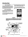
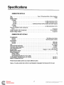
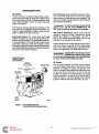
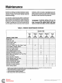
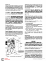
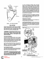
DKD
Y
Printed in USA.
981-0124
7-95
Redistribution or publication of this document
by any means, is strictly prohibited.
Safety Precautions
Before operating the generator set, read the Operator's
Manual and become familiar with it and the e ui ment. Safe
and efficient operation can be achieved on y f the unit is
proper1 operated and maintalned. Many accidents are
caused y failure to follow fundamental rules and precautions.
The following symbols,found throughoutthis manual, alert you
to potentiall dangerousconditionsto the operator, servicepersonnel, or t e equipment.
Thls symbol warns of immediate hazards whlch will result In severe personal Injury or
death.
1-1
Thls symbolrefers to a hazard or unsafe
practice whlch can result in severe personal injury
or death.
9P
i
;
1-
Thls symbol refers to a hazard or unsafe
practice whlch can result in personal Injury or product or property damage.
FUELAND FUMESARE FLAMMABLE. Fire, explosion, and
personal injury can result from improper practices.
DO NOTfill fuel tanks while engine is running. Fuel contact
with hot engine or exhaust is a potential fire hazard.
DONOTSMOKEOR USEAN OPEN FLAMEnearthe generator set or fuel tank.
Fuel lines must be adequately secured and free of leaks.
Fuel connection at the engine should be made with an approvedflexible,non-conductiveline. Donot use copper piping on flexible lines as copper will work hardenand become
brittle.
Be sure all fuel supplies have a positive shutoff valve.
GASOLINE AND LPG FUEL MAY BE ACCIDENTALLY IGNKEDBY ELECTRICALSPARKS, resentingthe hazardof
fire or expioslon, which can resu t In severe personal lnjury or death. When installing the generator set:
Do not tie electricalwiring to fuel lines.
Do not run electrical lines and fuel lines through the same
compartment openings.
Keep electricaland fuel lines as far apart as possible.
Place a physical barrier between fuel lines and electrical
lines wherever possible.
If electricaland fuel lines must pass through the same compartment opening, make certain that they are physically
separated by running them through individual channels, or
by passing each line through a separate piece of tubing.
DO NOTSMOKE while servicing batteries. Lead acid batteries emit a highly explosive hydrogengas that can be ignited by electricalarcing or by smoking.
EXHAUST GASES ARE DEADLY
Never sleep in the vehicle with the generator set runningunless vehicle is equippedwith an operatingcarbon monoxide
detector.
Providean adequate exhaust system to properly expel discharged gases. inspect exhaust system daily for leaks per
the maintenance schedule. Be sure that exhaust manifolds
are secure and not warped. Do not use exhaust gases to
heat a compartment.
Be sure the unit is well ventilated.
MOVING PARTS CAN CAUSE SEVERE PERSONAL INJURY OR DEATH
Beforestartingwork on the generatorset, disconnectbatteries, This will prevent accidental arcing.
P
Keep your hands away from moving-parts.
Make sure that fasteners on the generator set are secure.
Tighten supports and clamps, keep guards in position over
fans, drive belts, etc.
Do notwear loose clothing or jewelry while working on generator sets. Loose clothing andjewelry can become caught
in moving parts. Jewelry can short out electrical contacts
and cause shock or burning.
If adjustmentmust bemadewhiletheunit is running, use extreme caution around hot manifolds, moving parts, etc.
ELECTRICALSHOCKCAN CAUSESEVERE PERSONAL
INJURY OR DEATH
Disconnect starting battery before removing protective
shields or touching electrical equipment. Use rubber insulative mats placed on dry wood plalforms over floors that are
metalor concretewhen around electricalequipment. Do not
wear damp clothing(particularlywetshoes) or allow skinsurfaces to be damp when handling electricalequipment.
Use extreme caution when working on electrical components. High voltages can cause injury or death.
Followall state and localelectricalcodes. Have all electrical
installations performed by a qualified licensed electrician.
Tag open switches to avoid accidental closure.
DO NOT CONNECT GENERATOR SET DIRECTLY TO
ANY BUILDING ELECTRICALSYSTEM. Hazardousvoltages canflow from the generatorset intothe utility line. This
creates a potential for electrocution or property damage.
Connect only through an approveddevice and after building
main switch is open. Consult an electrician in regard to
emergency power use.
GENERAL SAFETY PRECAUTIONS
Haveafire extinguishernearby. Maintainextinguisherproperly and become familiar with its use. Extinguishers rated
ABC by the NFPA are appropriatefor all applications. Consult the local fire department for the correct type of extinguisher for various applications.
Hot coolants under pressurecan cause severe personal injury. DONOTopena radiatorpressurecap while the engine
is running. Stop the engine and carefully bleedthe system
pressure.
Benzene and lead, foundin some gasoline, have beenidentified by some state and federal agenciesas causingcancer
or reproductivetoxicity. When checking, draining or adding
gasoline, take care notto ingest, breathethe fumes, or contact gasoline.
Used engine oils have been identifiedby some state or federal agencies as causing cancer or reproductive toxicity.
When checking or changing engine oil, take care not to ingest, breathe the fumes, or contact used oil.
Removeall unnecessary grease and oil fromthe unit. Accumulated grease and oil can cause overheating and engine
damage, which presents a potentialfire hazard.
DO NOTstore anything in the generator compartment such
as oil or gascans, oilyrags, chains, wooden blocks, portable
propane cylinders, etc. A fire could result or the generator
set operation (cooling, noise and vibration) may be adversely affected. Keepthecompartment floor cleanand dry.
Do not work on this equipment when mentally or physically
fatigued, or after consuming any alcohol or drug that makes
the operation of equipment unsafe.
Redistribution or publicationRV-9
of this document
by any means, is strictly prohibited.
Table of Contents
PAGE
TITLE
.................................................................Inside Front Cover
................................................................................. i
.......................................................................................1
.................................................................................... 1
................................................................................ 1
...................................................................................... 2
........................................................................................... 3
.............................................................................................3
................................................................................... 3
........................................................................................
3
..............................................................................................4
............................................................................................ 5
..........................................................................5
......................................................................................6
.........................................................................................7
.......................................................................7
............................... .............................................. 8
.................................... ............................................... 8
....................................... ............................................. 9
.............................................. ............................................. 10
.......................................................................................11
........................................... .............................................
.............................................................................................13
....................................................................................... 13
.................................................................................14
.............................................................................................
14
............................................................................14
SAFETY PRECAUTIONS
TABLE OF CONTENTS
INTRODUCTION
About this Manual
How to Obtain Service
SPECIFICATIONS
OPERATION
General
Pre-Start Checks.,
Control Panel
Starting
Stopping
Operating Recommendations
Troubleshooting
MAINTENANCE
Periodic Maintenance Schedule
Generator Set Inspection
Lubrication System
Cooling System
Fan Belt
Fuel System
Air Cleaner
Battery
AC Generator
Crankcase Breather
Muffler
Out-of-Service Protection
a n
I I
California
Proposition 65 Warning
Diesel engine exhaust and some of its constituents are known
to the State of California to cause cancer. birth defects. and
other reproductive harm
.
i
Redistribution or publication of this document
by any means, is strictly prohibited.
Redistribution or publication of this document
by any means, is strictly prohibited.
Introduction
ABOUT THIS MANUAL
When contacting an Onan dealer or distributor, always
supply the complete Model number and Serial number
as shown on the Onan nameplate. See Figure 1.
This manual provides information for operating and
maintaining the Onan DKD generator set. Study this
manual carefully and observe all warnings and cautions. Using the generator set properly and following a
regular maintenance schedule will result in longer unit
life, better performance, and safer operation.
The Onan nameplate is located on the side of the generator control box on the 7.5 DKD, 6.5 DKD, and 6.0 DKD,
and is located on the side of the belt guard on the 8.0
DKD.
HOW TO OBTAIN SERVICE
When the generator set requires servicing, contact an
Onan dealer or distributor for assistance. Onan factory
trained parts and service representatives are ready to
handle all service needs.
A copy of the warranty (form AB355) and a parts catalog
is in the literature package included with the unit. A
service manual isavailableon specialorder through the
Onan dealer or distributor.
FIGURE 1. ONAN NAMEPLATE
INCORRECTSERVICE OR REPLACEMENT OF PARTS CAN RESULTIN SEVERE
PERSONAL INJURY, DEATH, AND/OR EQUIPMENT DAMAGE. SERVICE PERSONNEL MUSTBE QUALIFIED TOPERFORM ELECTRICALAND/OR MECHANK A L SERVICE.
FIGURE 2. 6.5/7.5 DKD GENERATOR SET FOR RECREATIONAL VEHICLE
1
Redistribution or publication of this document
by any means, is strictly prohibited.
Specifications
GENERATOR DETAILS
Type ............................................Onan, YD Revolving Field, &Pole, Brushless
Phase ..........................................................................
Single
Standby ratings:
60 Hertz
6.5 DKD ...................................................
6.5kW (6.5 kVA @ 1.0 PF)
7.5 DKD ...................................................
7.5 kW (7.5 kVA @ 1.0 PF)
8.0 kW (8.0 kVA @ 1.0 PF): Includes fan load if required
8.0 DKD ............................
50 Hertz
6.0 DKD ...................................................
6.0 kW (6.5kVA @ 1.0 PF)
Frequency regulation under varying load:
60 Hz ....................................................................
ltr5 percent
3 Hz maximum
Voltage regulation under varying load: ..........................................
Random voltage variation: .......................................................
z!2 percent
GENERATOR SET DETAILS
Air requirements
1200ft3/min(34m3/min)
60Hertz ......................................................
50 Hertz .....................................................
1000 ft3/min (28.3 m3/min)
Engine Speed
60Hertz .................................................................
1800r/min
50Hertz .................................................................
1500r/min
Fuel .......................................................................
No. 2 Diesel
Fuel Pump Inlet Thread Size ......................................................
1/8 NPTF
118 NPTF
Fuel Return Outlet Thread Size ....................................................
3 ft. (0.9 m)
Fuel Pump Maximum Lifl ........................................................
Flange or 1 4 4 in. NPT External
Exhaust Outlet ...............................................
Starting System Voltage ...............................................................
12
Battery Requirements
BatteryVoltage ...................................................................
12
Quantity Required ..................................................................
1
Cold Cranking Amps @ 0" F (-17.8" C) 425
*Cooling System Capacity (Engine and Radiator) .....................................
4 qt (3.8 L)
4 qt (3.8 L)
Engine Oil Capacity with Filter ...................................................
'Remote mount radiator systems may require additional coolant.
THE 6.5,7.5 AND 8.0 DKD ARE LISTED BY NATIONWIDE CONSUMER TESTING INSTITUTE, INC.
2
Redistribution or publication of this document
by any means, is strictly prohibited.
Operation
1 AWARNINGI
EXHAUST GAS IS DEADLY!
Exhaust gases contain carbon monoxide, an odorless and colorless gas. Carbon
monoxide is poisonous and can cause unconsciousnessanddeafh. Symptomsof
carbon monoxide poisoning can include:
0
0
0
0
Dizziness
Nausea
Headache
Weakness and Sleepiness
0
0
0
Throbbing in Temples
Muscular Twitching
Vomiting
Inability to Think Coherently
IF YOU OR ANYONE ELSE EXPERIENCEANY OF THESE SYMPTOMS, GET OUT
lNT0 THE FRESH AIR IMMEDIATELY. lf symptoms persist, seek medical attention. Shut down the unit and do not operafe until it has been inspected and
repaired.
Never sleep in vehicle with the generator set running unless the vehicle interior is
equipped with an operating carbon monoxide detector. Protection against carbon
monoxide inhalation also includes proper exhaust system installation and visual
and audible inspection of the complete exhaust system at the start of each
generator set operation.
GENERAL
CONTROL PANEL
This section covers starting and operatingthe generator
set. It is recommended that the operator read through
this entire section before attempting to start the set. It is
essential that the operator be completely familiar with
the set for safe operation.
The following describes the function and operation of
the generator set controls. Control switches and circuit
breakers are located on the face of the control panel as
shown in Figures 3 and 4.
The 8.0 DKD DC control box is designed for remote
mounting applications.
PRE-START CHECKS
Before starting, be sure the following checks have been
made and the unit is ready for operation. Refer to the
MAlNTENANCE section for the proper procedures.
GaugedMeters and Switches
Start-Stop Switch:Starts and stops the unit locally. The
unit may also be operated from a remote switch wired to
the control panel.
Lubrication
Check the engine oil level. Keep oil level near as possible to the dipstick full mark. Do not overfill.
Running Time Meter: Registers the total number of
hours that the unit has run.
Coolant
Use it to keep a record for periodic servicing. Time is
cumulative; meter cannot be reset.
The coolant level should be near the top of the fill cap.
Do not check while the coolant is hot.
If equipped, the running time meter on the 8.0 DKD will
be remotely located.
Thesudden release ofpressure from
a heated cooling system can result in
possible severe personal injury from the hot coolant.
Remove fhe expansion tank pressure cap slowly after
the engine has cooled.
@@@%I
Circuit Breakers
Fault Breaker:A manual reset breaker that shuts down
the engine for low oil pressure, high coolant temperature, high exhaust temperature and overspeed.
Fuel
Make sure the fuel tanks are full and the fuel system
primed for operation (see MAlNTENANCEsection).
Battery Charge Breaker: A 15 ampere breaker protecting the DC voltage regulator, alternator and wiring from
short circuits or overload.
Fuel presents the hazard of fire or
explosion which can cause severe
personal injury or death. Do not permit any flame,
spark, pilot light, cigarette, or other ignition source
near fhe fuel system.
Control Breaker: A 15 ampere DC breaker providing
protection to the control box wiring and remote wiring
from short circuits or overload. Also serves as an emergency stop switch.
3
Redistribution or publication of this document
by any means, is strictly prohibited.
Line Circuit BreakecThe AC output line circuit breaker(s) is mounted on the side of the control box on the
7.5 DKD, 6.5 DKD and 6.0 DKD. See Figure 3. The line
circuit breaker is customer supplied on the8.0 DKD and
location may vary.
The line circuit breaker protects the generator from a
short circuit or other overload.
Fan Circuit Breaker: The 8.0 DKD has a 15 ampere
circuit breaker mounted on the side of the AC control
box (see Figure 4). It protects the generator from a short
or overload in the circuit provided for operating an AC
remote radiator cooling fan (not used if a 12 VDC fan is
used).
STARTING
Starting at Control Panel
The following steps outline the correct procedures for
starting the generator set at the generator control panel.
The DC Control Breaker must be in the ON position.
1. Press the Start/Stop/Preheat switch toward the
Preheat/Stop positionfor 10to 30 seconds depending upon temperature as shown in Table 2. Do not
exceed 30 seconds.
Preheat time longer than 30
seconds can damage glow
plugs.
TABLE 2. PREHEAT TIME
LINE CIRCUIT
BREAKER SIDE OF CONTROL
BOX
CONTROL
BREAKER
I
/
RUNNING
TIME
METER
FAULT
BREAKER
STARTISTOP
PREHEAT
SWITCH
1
Ambient Temperature
Preheating Tlme
Above 86OF (3OOC)
About 10 sec.
Between 50' to 86'F (10' to 30'C)
About 15 sec.
Between 32' to 5OoF(0' to l0'C)
About 20 sec.
Below 32' F (OOC)
About 30 sec.
2. Release the switch from the Preheat position and
push it toward the Start position. This activates the
engine control and starting system. The starter will
crank and after a few seconds the engine should
start. The starter will automatically disconnectwhen
the generator AC voltage builds up.
3. If engine does not start after cranking 30 seconds,
release Start switch. Wait two minutes and then
repeat Steps 1 and 2.
\
BATERY
CHARGE
-. .. .. .-BREAKER
FIGURE 3. 7.5,6.5 AND 6.0 DKD CONTROL BOX FRONT PANEL
Excessive cranking periods can
overheat and damage the starter. Do not engage starter for periods longer than
30 seconds without allowing two minutes for starter to cool.
,-
START-STOP-
I
4. If enginedoes not starton second try, checkthe fuel
DC CHARGING
BREAKER
BREAKER
supply and be sure system has been primed. If the
generator set runs out of fuel, the fuel system may
need priming before it will start. See Fuel System in
the MAINTENANCE section.
Remote Starting
If generator set is started from a remote location, the
same proceduresand cautionsas for starting at the
control panel should be followed.
Start-up Checks
FG
I URE
4. DC CONTROLBOX mom PANEL
(REMOTE-MOUNT VERSION)
Check gauges on the remote control panel (if
equipped)afterthe engine is started. Observe the oil
pressure gauge immediately.
Redistribution or publication of this document
by any means, is strictly prohibited.
Exercise Period
Oil Pressure Gauge:The oil pressure should be in the
range of 35 to 50 psi (241to 345 kPa) when the engine is
at operating temperature, but may vary below this range
under various conditions.
Infrequent use can result in difficult starting and moisture condensation problems.This moisture is a result of
the engine not being run long enough to reach normal
operating temperature and might show up as water in
the oil in extreme causes. If this happens severe engine
damage might result. Operate the generator set under
load, at least one hour per week.
DC Voltmeter: Normal B t battery voltage during operation should be 14 to 15 volts.
Wafer Temperature Gauge: The water temperature
should be in the range of 165’ to 195OF (74’ to 91OC)
depending on the load and ambient temperature.
Exercising for one longer period each week is better
than several shorter periods of operation. Do NOT operate the set for extended periods at no load.
STOPPING
Before Stopping
Low Temperature, High Altitude Operation
Run the generator set at no loadfor three to five minutes
before stopping. This allows the lubricating oil and
engine coolant to carry heat away from the combustion
chamber and bearings.
1. Use correct SAE oil for temperature conditions.
Change oil only when warm. See Table 4.
2. Use No. 1 diesel fuel for temperatures lower than
14OF (-10’C) or for all temperatures if altitudes are
above 5000 feet (1500 m). The fuel should have a
cetane rating of at least 40 and have less than 0.5
percent sulfur if possible. Decrease oil change
interval by half if sulfur content is higher.
1-
Failure to a//ow running time for
engine cooling without load can
resultin engine damage. Make sure generator set runs
unloaded for at least three minutes.
To Sfop:Place the Start-Stop switch or the remote starting switch to the Stop position.
Extremely Dusty or Dirty Conditions
Observe the following items during operation in
extremely dusty or dirty environments:
OPERATING RECOMMENDATIONS
Break-In
0
Drain and replace the crankcase oil after the first 35
hours of operation on new generator sets. Refer to the
MAINTENANCE section of this manual for the recommended procedures.
0
0
0
Keep unit and radiator cooling surfaces clean.
Service air cleaner more frequently as necessary.
Change crankcase oil every 50 operating hours.
Clean generator as necessary. See MAINTENANCE Section.
No-Load Operation
Hold periods of no-load operation to a minimum and
avoid if possible. No-load operation allows combustion
chamber temperatures to drop so low that the fuel does
not burn completely. This results in carbon deposits
which can clog injectors, cause piston rings and valves
to stick and can cause cylinder glazing. If it is necessary
to run the engine for long periodsat no load, connect a
“dummy” electrical load to the generator.
5
Redistribution or publication of this document
by any means, is strictly prohibited.
TROUBLESHOOTING
Low Oil Pressure: Remove dipstick and cheqk oil level.
If low, add oil to bring level up to full mark. Inspect
engine exterior for leaks and repair as necessary. The
oil pressure switch actuates the fault circuit if pressure
drops below 9 psi (62 kPa).
DC Control
The DC control has a number of sensors that continuously monitor the engine for abnormal conditions such
as low oil pressure and high coolant temperature. If any
one of these conditions occur, the control stops the
engine. See Figure 5.
Crankcasepressure can blow out hot
oil and cause SEVERE burns. Do
NOT check oil while the generator set is operating.
The following sections describe the operation of the
fault systems and suggested items the operator can
check. If a major problem is indicated, contact an Onan
dealer or distributor for help or service.
High Coolant Temperature: If fault occurred during
operation, observe Coolant Temperature Gauge
(option) for indication of temperature over 250' F
(727OC). The coolant thermostat switch closes at .this
temperature and actuates the fault circuit.
Fault Reset Breaker: The control panel Fault Reset
breaker will trip for any one of the fault conditions described separately below. The white breaker reset button pops out about 1/4 inch (6 mm) when a fault occurs.
Locate the problem and make the necessary corrections before resetting breaker and starting the generator
set. All fault shutdowns except overspeed are delayed 5
seconds to avoid nuisance tripping.
Check coolant level in radiator after allowing engine to
cool down. Ensure pump belt is OK and has proper
tension. Also check cooling system cleanliness (freedom from contaminants, rust, sludge build-up, etc.).
Contact with hot coolant can result in
SEVEREburns.Allow cooling system
to cool before releasing pressure and removing radiator cap or release of hot coolant can result,
NOTE GENSETAPPEARANCE MAY VARY FROM
THIS ILLUSTRATION.
LOW OIL
PRESSURE
SWITCH/SENDER
AC Control
The AC control consists of the line circuit breakers
connected between the generator output and the load.
Breakers are required to protect the generator from
shorts or overload. When supplied by Onan they mount
on the side of the control box on the 7.5, 6.5 and
6.0 DKD. See Figure 5. The 8.0 DKD has a fan circuit
breaker mounted on the side of the AC control box as
shown in Figure 4. Line circuit breakers are customer
supplied on the 8.0 DKD and their location may vary.
COOLANT HIGH
TEMP. SWITCH
LI
RESET
BREAKER
ES-1551
FIGURE 5. FAULT SENSOR LOCATION
(7.5 DKD SHOWN FOR REFERENCE ONLY)
6
Redistribution or publication of this document
by any means, is strictly prohibited.
Maintenance
indicated or after the number of operating hours indicated, whichever comes first. Usethe table to determine
the maintenance required and then refer to the sections
that follow for the correct service procedures.
Establish and adhere to a definite schedule for maintenance and service. If the set will be subjected to extreme
operating conditions, the service intervals should be
reduced accordingly.
Consult with an authorized Onan dealer or distributor if
the generator set will be subjectedto any extreme operating conditions and determine a suitable schedule of
maintenance. Use the runningtime meter as a reference
to keep an accurate log of all service performed for
warranty support. Perform all service at the time period
1-
Accidental starting of the set can
cause severe personal injury or
death. Disconnect fhe negative battery cable when
repairs are made to the engine, controls, or generator.
TABLE 3. PERIODIC MAINTENANCE SCHEDULE
SERVICE TIME
SERVICE THESE ITEMS
Inspect Set
Check Oil Level
Check Coolant Level
Check Fuel Level
Check Air Cleaner Dust Cap (clean if req.)
Check Battery Charging System
Check Dive Belt Tension
Clean Out h a r k Arrester
Check Battery Specific Gravity
Change Crankcase Oil and Filter
Drain Water and Sediment from Fuel Filter
Check Anti-freeze
Clean Generator Assembly
Drain Sediment from Fuel Tank
Clean Crankcase Breather
Check Fuel Shut-Off Linkage
Change Fuel Filter Element
Change Air Cleaner Element
Clean Coolinn System
Daily
or
after
8 hours
after
after
x3
X
after
after
X’
X
X
X
x4
I
I
I
X
X
X2
X
X
X
x5
x3
X
X
I
I
I
I
I
I
x3
x
- Check for oil, fuel, cooling and exhaust system leaks. Check exhaust system audibly and visually with set running and repair any
leaks immediately. Replace corroded exhaust and fuel line components before leaks occur.
- Perform after first 35 hours of operation on new sets.
3 - Perform more often in extremely dusty conditions.
- Visually check belts for evidence of slippage.
- Drain one cup of fuel to remove water and sediment
1
2
4
5
7
Redistribution or publication of this document
by any means, is strictly prohibited.
GENERATOR SET INSPECTION
Mechanical
With the generator set stopped, check for loose belt,
fittings, leaking gaskets and hoses, or any signs of
mechanical damage. If any problems are found, have
them corrected immediately.With the set running, listen
for any unusual noises that may indicate mechanical
problems and check the oil pressurefrequently. Investigate anything that indicates possible mechanical
problems.
During operation, be alert for mechanical problems that
could create unsafe or hazardous conditions. The following sections cover several areas that should be frequently inspected to provide continued safe operation.
Engine Gauges (Optional)
Check gauges on the remote control panel (if equipped)
while the generator set is operating.
LUBRICATION SYSTEM
Oil Pressure Gauge: The oil pressure should be in the
range of 35 to 50 psi (241 to 345 kPa) when the engine is
at operating temperature, but may vary below this range
under various conditions.
The engine oil was drained from the crankcase prior to
shipment. Before the initial start, the lubrication system
must be filled with oil of the recommended classification
and viscosity. Refer to the Specifications section for the
lubricating oil capacity.
Coolant Temperature Gauge: The water temperature
should be in the range of 165' to 195OF (74' to 91OC)
depending on the load and ambient temperature.
Oil Recommendations
Use oils with the American Petroleum Institute (API)
classification S F X D in viscosities per temperature as
shown in Table 4.
DC Voltmeter: Normal B+ voltage during operating
should be 14 to 15 volts.
Exhaust System
TABLE 4. OIL SELECTION
With the generator set operating, inspect the entire
exhaust system includingtheexhaust manifold, exhaust
elbow, muffler and exhaust pipe. Visually and audibly
check for leaks at all connections, welds, gaskets, and
joints. If any leaks aredetected, shut down the generator
set and do not operate until corrected. Replace corroded exhaust components before leaks occur.
OIL VISCOSITY VS. TEMPERATURE
Exhaust gas presents the hazard of
severe personal injury or death.
Inspect exhaust system audibly and visually for leaks
daily. Repair any leaks immediately.
Fuel System
With the generator set operating, inspect the fuel supply
line, return line, filter, and fittings for leaks. Check any
flexible sections for cuts, cracks and abrasions and
make sure they are not rubbing against anything that
could cause breakage. Replace worn fuel line components before leaks occur.
32
10 20 30 40 50 w 70 80 0 0 1 ~ 1 1 0 1 ~
0
0c-34-29-23-18-12 -7 -1 4 10 16 21 27 32 38 43 48
OF--20-10
o
Anticipated Ambient Temperature
detected, have them corrected immediately.
When selecting the oil viscosity, pick the viscosity that is
right for the lowest temperature expected. Oil that is too
thick may result in a lack of lubrication when the engine
is started. Use a lower viscosity oil as the ambient
temperature reaches the lower end of the scale.
DC Electrical System
Do not use synthetic oil, non-detergent oil, and do not
mix different brands of oil.
Fuel presents the hazard of fire or
k&@!
@
%l
explosion which can result in severe
personal injury or death if ignited. If any leaks are
With the generator set off, check the terminals on the
battery for clean and tight connections. Loose or corroded connectionscreate resistance which can hinder
starting. Clean and reconnectthe battery cables if loose.
Always connect the negative battery cable last to
reduce the possibility of arcing.
Engine Oil Level
Check the engjne oil level during engine shut-down
periods at the intervals specified in the Maintenance
Table. The oil dipstick and oil fill are located on the side
of the engine (see Figure 6). The dipstick is stamped with
FULL and ADD to indicate the level of oil in the crankcase. For accurate readings, shut off the engine and
wait approximately 10 minutes before checking the oil
level. This allows oil in the upper portionof the engine to
drain back into the crankcase.
Ignition of explosive battery gases
can cause severe personalinjury. Do
not smoke while servicing batteries.
8
Redistribution or publication of this document
by any means, is strictly prohibited.
COOLING SYSTEM
Keep the oil level as near as possible to the FULL mark
on the dipstick. Removethe oil fill cap and add oil of the
same quality and brand when necessary.
The cooling system on each set is drained prior to
shipping and must be refilled before being operated.
The cooling system capacity of the standard unit with
set mounted radiator is shown in the SPEClFlCATlONS
section.
Do not operate the engine with the oil
below the ADD mark or above the
FULL mark. Overtilling can cause foaming or aeration
of the oil, while operation below the ADD mark might
cause loss of oil pressure.
The 8.0 DKD does not have an Onan supplied radiator.
This unit is provided for custom installations and may
have a vertical or horizontal mount remote radiator.
Horizontal mounted radiator systems requirean expansion tank that must be mounted at the highest point of
the cooling system.
1-
Improper operation can result in
overheating and equipment damage.
With custom installations that use a common radiator
for both vehicle engine and generator set cooling, do
NOT operate the vehicle engine and the generator set
at the same time or equipment damage can result due
to overheating.
Coolant Requirements
Asatsifactoryenginecoolant inhibits corrosion and protects against freezing. A solution of ethylene glycol anti
freeze (permanent type) and water is recommended for
normal operation and storage periods. Choose only a
reliable brand of antifreeze that contains a rust and
corrosion inhibitor but does not contain a stop-leak
additive.
The water used for engine coolant should be clean, low
in mineral content, and free of any corrosive chemicals
such as chloride, sulphate, or acid. Use soft water whenever available. Well water often contains lime and other
minerals which eventually may clog the radiator core
and reduce the cooling efficiency.
FIGURE 6. ENGINEOIL
Oil and Filter Change
Change the oil and filter at the intervals recommended
in the maintenance table. Use oil that meets the API
classification and viscosity requirementsas indicated in
the previous section.
Be sure the antifreeze solution will protect the cooling
system during the coldest weather. A 50/50solution of
ethylene glycol and water is applicable for most applications. This solution will protect the cooling system to
-35OF (-37OC) temperature.
Engine Oil Change: Run engine until thoroughly warm
before draining oil. Stop the engine, place a pan under
the drain outlet and open the drain valve. After the oil is
completely drained, close the drain valve. Refill with oil
of the correct API classification and appropriate SAE
viscosity for temperature conditions.
i
Filling the Cooling System
Verify that all drain cocks are closed and all hose
clamps secure. Remove the radiator pressure cap and
slowly add coolant until level is near the top of radiator.
Hot crankcase oil can cause burns if
it is spilled or splashed on skin. Keep
fingers and hands clear when removing the oil drain
plug and wear protective clothing.
Exceeding the recommended fill rate
can cause incomplete filling of the
engine block which can result in possible engine damage during warm-up. Always follow the recommended
fill procedure.
Oil Filter Change: Spin off oil filter and discard it. Thoroughlycleanfilter mounting surface.Applyathin film of
oil to filter gasket and install new element. Spin element
on by hand until gasket just touches mounting pad and
then turn an additional 1/2 turn. Do not overtighten.
Add coolantto the recoverytank (or separate expansion
tank if equipped) to the full-cold level.
With oil in crankcase, start engine and check for leaks
around filter element. Retightenonly as much as necessary to eliminate leaks, but do not overtighten.
When the engine is first started, remove the pressure
cap and monitor the coolant level. As trapped air is
expelled from the system, the coolant level will drop and
additional coolant should be added. Replace the pressure cap when the coolant level is stable.
9
Redistribution or publication of this document
by any means, is strictly prohibited.
Coolant Level
FlushingfAfter cleaningor before filling the system with
new coolant, drain the block and radiator and fill with
clean water. Operate the set for 10 minutes and then
drain the system completely. Refill with the recommended coolant.
Check the coolant level during shutdown periods at the
intervals specified in the Periodic Maintenance Schedule. Check by observing the coolant level in the recovery tank (or separate expansion tank if equipped) when
the system is cold. See Figure 7 for typical cooling
system. Engine coolant is at proper level when the recovery tank level is between Full and Low marks.
Never pour hot water into a cold
engine or cold wafer into a hot
engine. Doing so can crack the head or the cylinder
block. Do not operate the unit without water for even a
few minutes.
Contact with hot coolant can cause
severe burns. Allow cooling system
to cool before releasing pressure and removing radiator cap or release of hot coolant can result.
Thermostat
1-
Replace thermostat when it is broken, corroded, or
sticks in the open or closed position. If engine overheats
or does not reach and maintain a minimum operating
temperature, the thermostat should be removed and
tested as a possible cause.
The High Engine TemperatureCutoff
will shut down engine in an overheat
condition only if coolant level is sufficiently high to
physically contact shutdown switch. f oss of coolant
will allow engine to overheat without protection of
shutdown device, causing severe damage to engine. If
is therefore imperative that adequate engine coolant
levels be maintained for operational integrity of the
cooling system and overheat shutdown protection.
The thermostat can be removed for testing or replacement using the following procedure:
1. Drain cooling system.
2. Remove capscrews and washers that secure thermostat cover to water pump housing.
3. Raise thermostat cover with radiator hose intact and
position it to one side.
4. Remove thermostat cover gasket and thermostat.
5. Clean, inspect, and remove any gasket material
from the thermostat cover and housing.
Flushing and Cleaning
For efficient operation, the cooling system should be
drained, flushed, and refilled once a year. To drain the
system completely, the radiator drain and the cylinder
block drain located on the left side of engine must be
opened. See Figure 7.
Chemical Cleaning:Thoroughly clean the cooling system if rust and scale have collected on the engine water
jacket or in the radiator. Rust and scale slow down heat
absorption and can block the coolant flow. Use a good
radiator cleaning compound in accordance with instructions furnished by the supplier.
THERMOSTAT
Use a new gasket when replacing thermostat. Refill
cooling system with the recommended antifreeze
coolant.
Pressure Cap
Closed cooling systems make use of a pressurized cap
to increase the boiling point of the coolant and allow
higher operating temperatures. Pressure caps should
be replaced every two years or sooner if they malfunction.
J R A D I A T O R CAP RECOVERY
%
FAN BELT
(MODELS EQUIPPED WITH RADIATOR)
BRACKET
A loosened fan belt can cause the engine to overheat. If
this occurs, loosentheadjusting nut and tighten the belt.
Be sure to retightentheadjustmg mtaftertheadjhstment.'
OVERFLOW
HOSE
Proper fan belt tension is such that the belt deflects
about 0.4 in. (10 mm) at the middle when pressed with a
finger [at a force of 22 Ibs. (10 kg)]. See Figure 8.
J
The belt can be removed for inspection or replacement
by loosening the adjustment nut and pushing alternator
inward. Inspectfan belt for excessive slickness, oil soak,
wear, tear, cracks and overstretching. Replace if
needed.
Contact with rotating machinery can
cause severe personal injury or
death. Stay clear of rotating components and secure
guards and shields in place before operatingmachinery.
ANCE MAY VARY FROM
/
lZEEEl
FIGURE 7. TYPICAL COOLING SYSTEM COMPONENTS
10
Redistribution or publication of this document
by any means, is strictly prohibited.
I
To avoid condensation problems, keep fuel supply
tanks as full as possible by filling up each time the
engine is used. In cold weather, warm fuel returning
from the injectors heats the fuel in the supply tank. If the
fuel level is low, the upper portion of the tank tends to
form condensation. In warm weather, both the fuel and
the tank will be warm during the daytime. At night, cool
air tends to lower the temperature of the tank more
rapidlythan the temperature of the fuel. If the fuel level is
low, the upper portion of the tank will cool more rapidly
and tend to form condensation.
ADJUST TENSION
HERE
,&7
Condensation (water) can cause clogging of fuel filters
as well as freezing problems. in addition, water mixing
with the sulphur in the fuel forms acid which can corrode and damage engine parts.
ALTERNATOR
Priming the Fuel System
Thefuel system must be primed priorto initial startup or
after the engine has run out of fuel.
CS-1239
LowfressureFuelSysfem:The electricfuel pump,fuel
filter and injection pump inlet comprisethe low pressure
fuel system. To prime these components, follow the
same procedure as when the fuel filter is replaced (following section).
FIGURE 8. BELT TENSION ADJUSTMENT
FUEL SYSTEM
Use only a good quality fuel obtained from a reputable
supplier. The quality of fuel used is important in obtaining dependable performance and satisfactory engine
life. Fuels must be clean, completely distilled, well
refined, and non-corrosive to fuel system parts.
Be sure to check fuel level in fuel tank and that shut off
valve is open.
RX%N
Fuel presents the hazard of fire or
k&@!@d
explosion which can cause severe
personal injury or death. Do not permit any flame,
spark, pilot light, cigarette, or other ignition source
near the fuel system.
Fuel Recommendations
Use ASTM 2-D (No. 2 Diesel) or ASTM 1-D (No. 1 Diesel)
fuel with a minimum Cetane number of 45. Number 2
diesel fuel gives the best economy and performance
under most operating conditions. Use number 1 diesel
fuel when ambient temperatures are below 32OF (OOC)
and during long periods of light engine load.
1
-
Use low sulfur content fuel having a cloud point of at
least 10"F (6OC) below the lowest expected fuel
temperature. Cloud point is the temperature at which
wax crystals begin to form in diesel fuel.
Fuel Handling Precautions
Take appropriate precautions to prevent the entrance of
dirt, water or other contaminants into the fuel system.
Filter or strain the fuel as the tank is filled.
Due to the precise tolerances of diesel injection systems, dirt or water in
the fuel can cause severe damage to both the injection
pump and injector nozzles. Take special precautions
to keep the fuel clean and free of water.
FS4615
FIGURE 9. INJECTION PUMP FUELSYSTEM
(7.5 DKD SHOWN FOR REFERENCE ONLY)
11
Redistribution or publication of this document
by any means, is strictly prohibited.
Fuel Filter
7.5 DKD, 6.5 DKD, 6.0 DKD
8.0 DKD
The filter replacement interval will vary according to the
fuel quality and cleanliness. Using the wrong fuel or
dirty fuel will shorten the service life of the filter.
Dirt or wafer in fhe sysfem will cause
severe damage to both fhe injection
pump and fhe injection nozzles. If is exfremely imporfanf fhe fuel be kept clean and free of water.
Refer to the Periodic Maintenance Schedule for the
recommended filter change interval. However, if the
engine shows signs of fuel starvation (reduced power or
surging), change the fuel filter.
FS-1696
To Service 7.5 DKD, 6.5 DKD and 6.0 DKD:
FIGURE 10. FUEL FILTER ASSEMBLY
1. Loosen drain and bleed screws. Collect fuel in suitable container. Remove bleed plug. See Figure 10.
2. Remove filter element from head with the bowl
connected.
3. Clean bowl, O-ring gland and O-ring.
4. Lubricate O-ring with clean diesel fuel and place in
bowl gland.
5. Spin bowl onto new element. DO NOT OVERTIGHTEN.
6. Lubricate element and gasket and fill bowl and element with clean diesel fuel.
7. Spin bowl and element assembly onto head and
hand tighten.
8. Disconnect starter solenoid lead at terminal connector. This allows fuel pump operation without
cranking engine.
9. Depress Start switch until fuel purges at bleed
screw and bleed plug opening.
10. Replace bleed plug and close bleed screw. Reconnect starter lead.
High Pressure Fuel Sysfem: The injection pump, fuel
injection lines and fuel injectors comprise the high
pressure fuel system. This part of the system is usually
self-priming since any trapped air is usually forced out
through the injection nozzles.
AIR CLEANER
The air cleaner is not Onan supplied on the 8.0 DKD and
may vary from the air cleaner described here.
The air cleaner element is a dry type and should never
have oil appliedto it. Avoid touching the element except
when cleaning it (Figure 11). Instructions for cleaning
the element are on a label attached to the element.
The dust cup should be cleaned once a week, or every
day in extremely dusty conditions. Be sure the dust cup
“TOP” or arrow on the rear of cup is in the upright
position.
To Service 8.0 DKD:
If fhe dusf cup is mounfed incorrectly, dusf does nof collect in the
cup and can shorten life of fhe filfer element.
1. Loosen drain and bleed screws. Collect fuel in suitable container. Remove bleed plug. See Figure 10.
2. Remove filter element from head.
3. Lubricate new element and gasket and fill element
wjth clean diesel fuel.
4. Spin element onto head and hand tighten.
5. Disconnect starter solenoid lead at terminal connector. This allows fuel pump operation without
cranking engine.
6. Depress Start Switch until fuel purges at bleed plug
opening.
7. Replace bleed plug and close bleed screw. Reconnect starter lead.
Change the element yearly, or more often in extremely
dusty conditions.
AIR CLEANER BODY
Fs1532
FIGURE 11. TYPICAL AIR CLEANER COMPONENTS
12
Redistribution or publication of this document
by any means, is strictly prohibited.
BATTERY
Do not add water in freezing weather
1 enough
- (two to three
unless the engine will run long
hours) to assure a thorough mix-
Check the condition of the starting battery at the interval
specified in the Periodic Maintenance Schedule.
Always disconnect the negative ground strap from the
battery before working on any part of the electrical system or the engine. Disregard the sections on Checking
Specific Gravity and Checking Electrolyte Level if using
a maintenance free type battery.
ing of water and electrolyte-
AC GENERATOR
There are no brushes, brush springs or collector rings
on these generators, therefore they require very little
servicing. Periodic inspections, to coincide with engine
oil changes, will provide good performance.
Ignition of explosive battery gases
@@@6l
can cause severe personal injury. Do
not smoke while servicing batteries.
I
Remove the generator end bell cover and inspect the
rotating rectifier assembly to make sure the diodes (see
Figure 12) are free of dust, dirt and grease. Excessive
foreign matter on thesediodesand heatsinkswill cause
the diodes to overheat and will result in their failure.
Blow out the assembly periodically with filtered low
pressure air.
Cleaning Battery
Keep the battery clean by wiping it with a damp cloth
whenever dirt appears excessive.
If corrosion is present aroundthe terminal connections,
remove battery cables and wash the terminals with an
ammonia solution or a solution consisting of 114 pound
(about 100 grams) of baking soda added to 1 quart
(about 1 litre) of water.
Accidental starting of the set can
ldeath.
aWARNl
N
Fl
cause severe personal injury or
Move the Operation Selector switch to STOP
and disconnect the starting battery before inspecting
rotating rectifier assembly.
Be sure the vent plugs are tight to prevent cleaning
solution from entering the cells.
Excessive foreign matter on diodes
and heat sinks will cause overheating and possible failure.
After cleaning, flush the outside of the battery and surrounding areas with clean water.
ROTATlNG
Keep the battery terminals clean and tight. After making
connections, coat the terminals with a light application
of petroleum jelly or non-conductive grease to retard
corrosion.
RECTIFIER
ASSEMBLY
Checking Specific Gravity
Usea battery hydrometertocheck the specificgravityof
the electrolyte in each battery cell.
1-
Battery electrolyte can cause severe
eye damage and burns to the skin.
Wear goggles, rubber gloves and a protective apron
when working with batteries.
4
Hold the hydrometer vertical and take the reading. Correct the reading by adding four gravity points (0.004) for
every five degrees the electrolyte temperature is above
8OoF(27OC) or subtractingfour gravity points for every
five degrees below 8OoF(27OC). A fully charged battery
will have a corrected specific gravity of 1.260. Charge
the battery if the reading is below 1.21 5.
\
\
v
ES-1223
FIGURE 12. GENERATOR END VIEW
Checking Electrolyte Level
Check the level of the electrolyte (acid and water solution) in the battery at least every 100 hours of operation.
If the cells are low on water, fill cells to the bottom of the
filler neck with distilled water and recharge. If one cell is
low, check case for leaks or for a bad cell. Keep the
battery case clean and dry. An accumulation of moisture
will lead to a more rapid discharge and battery failure.
Generator Bearing
Inspect the bearing for evidence of outer case rotation
every 1000 hours of operation. Replace the bearings
every five years. Deterioration of the bearing grease due
to oxidation makes this replacement necessary.
If generator requires major repair or servicing, contact
an authorized Onan dealer or distributor.
13
Redistribution or publication of this document
by any means, is strictly prohibited.
CRANKCASE BREATHER
MUFFLERISPARK ARRESTER
Clean the crankcase breather element at the scheduled
intervals. Service using the following procedure. Refer
to Figure 13.
Exhaustspark arresters are necessaryfor SAFE OPERATION. All require periodic clean-out to maintain maximum efficiency. See the maintenance schedule for
recommended cleaning intervals.
1. Removethree cap nuts and O-rings from the top of
cylinder head cover. Carefully remove the cover
trying not to damage gasket.
2. From inside the cover, removetwo machinescrews
securing the breather baffle, element, plate and
shield.
3. Clean element in a suitable solvent. Dry element,
then saturate with engine oil before replacing.
To clean the spark arrester, remove the 1/8 inch pipe
plug from the bottom of the muffler. Run the generator
set with load for five minutes. Stop the generator set and
allow the muffler to cool. Replace the pipe plug in the
muffler. See Figure 14.
Many cleaning solvents present
kiiBMEI
a hazard of severe personal
injury or death. Follow the manufacturer’s instructions and proceed with care.
4. If necessary, clean other breather components in a
suitable solvent before reassembling.
EXS-1124-1
FIGURE 14. EXHAUST MUFFLER
Cleaning the Generator Set
The generator set should be cleaned every six months
or sooner if severe road contamination or dusty conditions are encountered. Dust usually can be removed
with a damp cloth. Some road contaminants however,
may require steam for removal. Do not steam clean the
generator set while the engine is running. When cleaning, provide cover or protection so spray is not directed
into the generator, air cleaner, control box, fuel solenoid, or electrical connectors. Do not clean with solvents; they can damage electrical connectors.
OUT-OF-SERVICE PROTECTION
PLATE,
The inherent lubricating qualities of No. 2 diesel fuel
should protect the cylinders of a diesel engine for at
least 30 days when the unit is not in service. To protect
an engine that will be out of service for more than 30
days, proceed as follows:
-u
I
MACHINE
SCREWS
1. Exercise the generator set as described in the
OPERATlONsectionuntil the engine is up to operating temperature.
2. Shut down engine and disconnect the battery. Store
battery in a cool dry placeand connect to a charger
every 30 days to maintain full charge.
c-1102
FIGURE 13. CRANKCASE BREATHER ASSEMBLY
14
Redistribution or publication of this document
by any means, is strictly prohibited.
3. Clean and check battery. Measure specific gravity
[1.260at 8OoF(27OC)I and verify level to be at split
ring. If specific gravity is low, charge until correct
value is obtained. If level is low, add distilled water
and charge until specific gravity is correct. DO NOT
OVERCHARGE.
Battery electrolyte can cause
severe eye damage and burns to
the skin. Wear goggles, rubber gloves and a protective apron when working with batteries.
'I
3. Drain the oil base while still warm. Replace oil filter.
Refill crankcase and attach a tag indicatingviscosity of oil used.
4. Check the coolant level and add more coolant if the
level is low. If freezing temperatures are possible,
test strength of coolant mixture.
5. Plug exhaust outlets to prevent entrance of moisture, bugs, dirt, ect.
6. Clean and wipeentire unit. Coat partssusceptibleto
rust with a light coat of grease or oil.
Battery electrolyte can cause
@!@@!&I
severe eye damage and burns to
the skin. Wear goggles, rubber gloves and a protective apron when working with battery.
4.
5.
6.
7.
Prime the fuel system.
Connect starting battery (ground terminal last).
Remove all loads before starting the engine.
After start, apply load to at least 50 percent of rated
.capacity.
8. Check gauges for normal readings. Set is ready for
service.
Returning a Unit to Service
Refer to preceding paragraphs in this Maintenancesection for specific service procedures.
1. Remove plug from exhaust outlet.
2. Check tag on oil base and verify that oil viscosity is
still correct for existing ambient temperature.
15
Redistribution or publication of this document
by any means, is strictly prohibited.
Redistribution or publication of this document
by any means, is strictly prohibited.
Redistribution or publication of this document
by any means, is strictly prohibited.
Redistribution or publication of this document
by any means, is strictly prohibited.
Redistribution or publication of this document
by any means, is strictly prohibited.
Onan Corporation
1400 73rd Avenue N.E.
Minneapolis, MN 55432
1-800-888-ONAN
612-574-5000 international Use
Telex: 275477
Fax: 612-574-8087
Onan is a registered trademark of Onan Corporation
Redistribution or publication of this document
by any means, is strictly prohibited.


![T] .1](http://vs1.manualzilla.com/store/data/005831826_1-5c5b79be6c7f2f902c022f1ff12b7474-150x150.png)