1
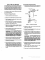
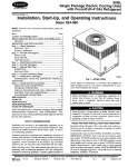
Operator’s Manual
Model BGD and NHD Generator Sets
Printed in U.S.A.
965-0129
4-93
Safetv Precautions
Before operating the generator set, read the Operator’s
Manual and become familiar with it and the ui ment. Safo
and efficient opwatlon can be achieved on y the unit is
properly operated and maintained. Many accidents are
caused by failure to follow fundamental rules and precautions.
The following symbols, found throughout this manual, alert you
to potentiall dangerous conditionstothe operator, servicepersonnel, or e equipment.
”IR
tx
This symbol warns o f immediate hazards which will result in severe personai injuty or
death.
@VZU”G
This symbol refersto a hazard or unsafe
practice wbich can result in severe personal Injuiy
or death.
hi CAUTIOi Thissymbol refersto a hazard or unsafe
---.practice which can resuit in personal injuv or product or property damage.
FUEL AND FUMES ARE FLAMMABLE. Fire, explosion. and
personal injury can result from improper practices.
DO NOTfill fuel tanks while engine is running. Fuel contact
with hot engine or exhaust is a potential fire hazard.
DO NOT SMOKE OR USEAN OPEN FLAMEnear the generator set or fuel tank.
Fuel lines must be adequately secured and free of leaks.
Fuel connection at the engine should be made with an a p
provedflexiMe, norrconductiveline. Do not use copper p i p
n g on flexible lines as copper will work hardenand become
brittle.
Be sure all fuel supplies have a positive shutoff valve.
GASOLINE AND LPG FUEL MAY BE ACCIDENTAUY IG
N E D BY ELECTRICALSPARKS, resentlngtheharsrdof
flre or explosion, which can resu t In severe personal Injury or death. When installlng the generator set:
P
Do not tie electrical wiring to fuel lines.
Do not run electrical lines and fuel lines through the same
compartmentopenings.
Keep electrical and fuel lines as far apart as possible.
Place a physical barrier between fuel lines and electrical
lines wherever possible.
H electrical and fuel lines must passthrough the same compartment opening, make certain that they are physically
separated by running them through individual channels. or
by passing each line through a separate piece of tubing.
DO NOT SMOKE while servicing batteries. Lead acid batteries emit a highly explosive hydrogen gas that can be ignited by electrical arcing or by smoking.
EXHAUST GASES ARE DEADLY
0
0
Never sleep inthe vehicle with the generator set running unless vehicle is equippedwith an operating carbon monoxide
detector.
Provide an adequate exhaust system to properly expel discharged gases. Inspect exhaust system daily for leaks per
the maintenance schedule. Ensurethat exhaust manifolds
are secure and not warped. Do not use exhaust gases to
heat a compartment.
Be sure the unit is wall ventilated.
MOVING PARTS CAN CAUSE SEVERE PERSONAL
JURY OR DEATH
0
IN-
Beforestarting work onthe generator set, disconnect batteries. This will prevent accidental arcing.
Keep your hands away from moving parts.
Make sure that fasteners on the generator set are
3.
Tighten supports and damps, keep guards in position over
4
fans, drive belts, etc.
Do not wear loose clothing or jewelry while working on generator seis. Loose clothing and jewelry can become caught
in moving parts. Jewelry can short out electrical contaqts
and cause shock or burning.
If adjustment must be made while the unit is running. use extreme caution around hot manifolds, moving parts. etc.
ELECTRICAL SHOCK CAN CAUSE SEVERE PERSONAL
INJURY OR DEATH
Disconnect starting battery before removing protective
shields or touching electrical equipment. Use rubber insulative mats placed on dry wood platforms over floors that are
metalor concretewhen around electricalequipment. Donot
weardampclothing (particularlywetshoes)orallowskinsurfaces to be damp when handling electrical equipment.
Use extreme caution when working on electrical components. High voltages can cause injury or death.
Followall state and localelectrical&des. Have all electrical
installations performed by a qualified licensed electrician.
Tag open switches to avoid accidental closure.
DO NOT CONNECT GENERATOR SET DIRECTLY TO
ANY BUILDING ELECTRICAL SYSTEM. Hatardous voltages canflow from the generatorset i n t o h utililine. This
creates a potential for electrocution ar property I
3.
Connect only through an approveddevice and aftei
g
main switch is open. Consult an eledriaan in rbyyIy ;o
emergency power use.
GENERAL SAFETY PRECAUTIONS
Haveafire extinguishernearby. Maintainextinguisher prop
erly and become familiar with its use. Extinguishers rated
ABC by the NFPA are appropriate for all applications. Consult the local fire department for the correct type of extinguisher for various applications.
Hot coolants under pressure can cause severe personal injury. DO NOTopena radiator pressurecap whilethe engine
is running. Stop the engine and carefully bleed the system
pressure.
Benzeneand lead, fwnd in some gasoline, have been iden-
tified by some state and federal agencies ascausing cancer
or reproductivetoxici. When checking, draining or adding
gasdine, take care not to ingest, breathe the fumes, or contact gasoline.
Used engine oils have been identified by some state or federal agencies as causing cancer or reproductive toxicity.
When checking or changing engine oil, take care not to ‘7gest, breathe the fumes, or contact used oil.
Removeall unnecessarygrease andoil from the unit. Accumulated grease and oil can cause overheating and engiy
damage, which presents a potential fire hazard.
DO NOT store anything inthe generator mmparbn
as oil or gas cam,oily rags, chains, wooden blocks,
;
I
0
propane cylinders, etc. A fire could result or the g
lr
set operation (cooling, noise and vibration) may be adversely affected. Keep the compartmentfloor clean and dry.
Do not work on this equipment when mentally or physically
Redistribution
publicationany
of this
document,
fatigued,
or afterorconsuming
alcohol
or drug that makes
byofany
means, isunsafe.
strictly prohibited.
the operation
equipment
RV-9
.
.
.
.
.
.
Table of Contents
SECTION TITLE
1
2
3
4
PAGE
................................
.....................................................
.................................................
...................................................
........................................................
....................................................
...............................................
..............................................
.................................................
...............................................
.............................................
....................................................
..........................................
.............................................
.....................................................
.................................................
...........................................................
.....................................................
.........................................................
.......................................................
...................................................
..........................................................
.........................................................
.......................................................
..........................
.........................................
SAFETY PRECAUTIONS
Inside Front Cover
INTRODUCTION
1-1
About This Manual
1-1
How to Obtain Service .............................................. 1-1
SPECIFICATIONS
2-1
OPERATION
3-1
3-1
Before Starting
Recommended Fuels
3-2
3-2
Starting and Stopping
3-2
Break-in Procedure
Operating Conditions
3-2
Generator Set Exercise
3-3
Remote Control
3-3
3-4
Out-of-Service Protection
3-5
Troubleshooting Guide
MAINTENANCE
4-1
General Inspection
4-1
Exhaust
4-1
Spark Arrester
4-1
Engine Oil
4-1
Periodic Maintenance Schedule ..................................... 4-2
4-4
Battery Care
4-4
Governor Linkage
Air Filter
4-4
4-5
Fuel Filter
Spark Plugs
4-6
4-6
Cleaning Carburetor. Combustion Chamber
4-7
Cleaning the Generator Set
Inspect and Clean Engine (internal) ..................................
4-7
i
Redistribution or publication of this document,
by any means, is strictly prohibited.
Redistribution or publication of this document,
by any means, is strictly prohibited.
Section 1 Introduction
s
ABOUT THIS MANUAL
HOW TO OBTAIN SERVICE
*
This manual covers the operation and maintenance of
the BGD and NHD commercial mobile generator sets.
For more information, see these publications:
When the set needs service, call an authorized service
center and give them the complete model number and
serial number listed on the generator set nameplate.
ElectricaVMechanicaI Fundamentals
(publication 932-0408)
Factory-trainedpartsand service centers can handle all
service needs. The Parts and Service Center Directory
(publication F-115,included) lists the nearest center.
Onan Generator Traininq Manual
(publication 932-0404)
BGD/NHD Installation Manual
(publication965-0629)
BGD/NHD Service Manual
(publication 965-0529)
Read this manual carefully, and follow all warnings and
cautions. Using the genset properly and following a
regular maintenance schedule can bring about longer
unit life, better performance, and safer operation. The
generator set must be installed properly to operate
safely.
IBat.
Time Rating
-
Insulation NEMA Class
1
I
I
Ambient 40°C
I
I
I
I
1
Wmng Diagram No. ( 5 )
FIGURE 1-1. ONAN NAMEPLATE
.
-
I
1-1
Redistribution or publication of this document,
by any means, is strictly prohibited.
Redistribution or publication of this document,
by any means, is strictly prohibited.
Section 2. Specifications
MODEL BGD
MODEL NHD
204 pounds (92 kg)
230 pounds (104 kg)
14 x 25-l/4 x 19 In.
(356 x 641 x 478 mm)
14-518 x 25-9/16 x 21-1/16 In.
(371 x 649 x 535 mm)
Minimum Free Area for
Ventilating Air
85 sq. In.
(548 sq. cm)
85 sq. In.
(548 sq. cm)
MinimumVertical Clearance
At Air Discharge Outlet
2 In. (51 mm)
2 In. (51 mm)
18 gauge, 1-38 In. ID
rigid steel tubing
18 gauge, 1-3/8 In. ID
rigid steel ubing
Engine Oil Capacity (Dry Filter)
3.5 quarts (3.3 L)
3/5 quarts (3.3 L)
Control Panel Fuse (Fl)
5 amps slow-blow
5 amps slow-blow
Ignition/Choke Fuse (F2)
10 amps
10 amps
0.025 In. (0.64 mm)
0.025 In. (0.64 mm)
6 psi (41 kPa)
6 psi (41 kPa)
3 Ft. (0.9 m)
3 Ft. (0.9 m)
Gasoline Supply Fitting
1/4 In. ID hose barb
114 In. ID hose barb
Min./Max. Propane Supply Pressure
(Vapor Withdrawal)
7/14 In.
(178/356 mm) WC
7/14 In.
(178/356 mm) WC
Propane Supply Connection
(Vapor Withdrawal)
3/4 In. NPTF tapping
3/4 In. NPTF tapping
Propane Supply Connection
(Liquid Withdrawal)
1/4 In. NPTF tapping
1/4 In. NPTF tapping
12
12
Cold Cranking Amps (SAE J537) for
Ambients Above/Below Freezing
360/450
360/450
Minimum RequiredVoltage at Starter
Motor Terminals During Cranking
8
8
Battery Charging Voltate (at No-LoadAC)
14.4
14.4
Battery Charging Voltate (at Full-Load AC)
14.6
14.6
Maximum Continuous
Battery Charging Amperage
10
10
Trickle Battery Charging Amperage
0.5
0.5
General
4
Weight
Overall Dimensions
(H x L x W)
RequiredExhaust
Pipe Material
Spark Plug Gap
Fuel Connections
Maximum Gasoline Supply Pressure
(at Carburetor)
Maximum Gasoline Fuel Pump Lift
Battery
Voltage
,
2-1
Redistribution or publication of this document,
by any means, is strictly prohibited.
Specifications (Cont.)
MODEL NHD
MODEL BGD
50 Hertz
(1500 RPM)
60 Hertz
(1800 RPM)
50 Hertz
(1500 RPM)
60 Hertz
(1800 RPM)
4.0 kW
4.5 kW
5.0 kW
6.5 kW
At 110/220 Volts
36.4R8.2 amps
-
45.5/22.7 amps
-
At 120/240 Volts
-
37.5A8.8 amps
-
54.2l27.1 amps
At 1101220 Volts*
21.0/10.5 amps
-
26.3/13.2 amps
-
At 120/240 Volts*
-
21.7/10.8 amps
-
31.3/15.7 amps
Under Full-Load
0.73 gph (2.8 Uh)
0.8 gph (3.0 Uh)
0.8 gph (3.0 Uh)
1.3 gph (4.9 Uh)
Under Half-Load
0.53 gph (2.0 Uh)
0.6 gph (2.3 Uh)
0.57 gph (2.2 L/h)
0.7 gph (2.5 Uh)
Under No-Load
0.35 gph (1.3 Uh)
0.4 gph (1.5 Uh)
0.35 gph (1.3 Uh)
0.4 gph (1.5 Uh)
3.5 kW
4.0 kW
5.0 kW
6.3 kW
At 110/220 Volts
31.8/15.9 amps
-
45.5122.7 amps
-
At 120/240 Volts
-
33.3116.7 amps
-
52.5126.3 amps
Under Full-Load
0.98 gph (3.7 Uh)
1.3 gph (4.9 Uh)
1.18 gph (4.5 Uh)
1.7 gph (6.4 Uh)
Under Half-Load
0.65 gph (2.5 Uh)
0.8 gph (3.0 Uh)
0.78 gph (3.0 Uh)
1.05 gph (4.0 Uh)
Under No-Load
0.4 gph (1.5 Uh)
0.5 gph (1.9 Uh)
0.5 gph (1.9 Uh)
0.65 gph (2.5 Uh)
*
Gasoline Fueled Sets
Rated Power Output
Full-Load Current
(1-Phase Generators
Full-Load Current
31-Phase Generators
Gasoline Consumption
Propane Fueled Sets
Rated Power Output
Full-Load Current
(1-Phase Generators)
Propane Consumption
.
-
* These values are for generators having a Series-Delta connection.
2-2
Redistribution or publication of this document,
by any means, is strictly prohibited.
CARBURETOR
BGD/NHD
(Gasoline
Fuel) SPARK
BOARD FUSE
PLUG\
BRACKET WITH RELAYS AND
BAllERY CHARGING
\
I
NEGATIVE (-)
BATTERY CABLE
BAlTERY CABLE
*\
UNE CIRCUIT
BREAKERS
MISW-lSr
FUEL PUMP AND FUEL INLET
.
CONNECTION
10 AivrP
IGNITION/CHOKE
ninru
unbuIT FUSE
I
\
REMOTE START CABLE
CONNECTION
BGD/NHD
(Liquid
. . LPG
Fuel)
CARBURETOR
AND GOVERNOR
SPARK BOARD FUSE ADJUSTMENTS
P 11110
anmr
.
I
PLUG
IGNITION
SPARK
AIR
COIL
BRAGKETWlTHREIAYSAND
BAllERY CHARGING
REGULATOR
BAiTERY CABLE
CONNECTION
(NON-EXTENDED
SHAFT MODELS)
I
LINE CIRCUIT
.BREAKERS
MOUNTlNGTRAY
BATE
FIGURE 2-1. BGD/NHD GENERATOR SETS
Redistribution or publication of this document,
by any means, is strictly prohibited.
2-3
\
.
Redistribution or publication of this document,
by any means, is strictly prohibited.
Section 3. Operation
EXHAUST GAS IS DEADLY!
Exhaust gases contain carbon monoxide, an odorless and colorless gas. Carbon
monoxide is poisonous and can cause unconsciousnessand death. Symptoms of
carbon monoxide poisoning can include:
Dizziness
Nausea
Headache
Weakness and Sleepiness
0
Throbbingin Temples
Muscular Twitching
Vomiting
Inability to Think Coherently
IF YOU OR ANYONE ELSE EXPERIENCEANY OF THESESYMPTOMS, GET OUT
INTO THE FRESH AIR IMMEDIATELY. If symptoms persist, seek medical affention. Shut down the unit and do not operate until it has been inspected and
repaired.
Never sleep in vehicle with thegenerator set running unless the vehicleinferior is
equipped with an operating carbonmonoxide defector. Protection against carbon
monoxide inhalation also includes proper exhaust system installation and visual
and audible inspection of the complete exhaust system at the start of each
generafor set operation.
BEFORE STARTING
Exhaust gases can cause severe
kate@the%generator
%
! l personalinjury
or death. Neveroperset unless the exhaust outlet is clear
General Inspection
Inspect the set and the entire exhaust system before
startup. Check for looseand damaged components and
fasteners, and correct all problem areas.
of walls, snow banks, or any obstructions that can
prevent exhaust gases from dissipating. Never operate
any exhaust fan in the vehicle when thegenerafor set is
running: an exhaust fan can draw exhaust gas into the
vehicle.
Exhaust gas presents the hazard of
k&@@!d
severe personal injury or death.
Make certain fhaf all exhaust components work cor-
Lubrication
rectly and are secure.
Check the engine oil level often. Keep the level near the
fill indicator FULL mark. Do not overfill. See Section 4,
Maintenance, for instructions.
Do not start the set while it is connected to a load. First,
make certain that any output switching device is in the
“Utility” position, and that the vehicle AC distribution
panel breakers are off (open). Do not start the set if
exhaustgases will not be effectively expelledaway from
the vehicle. Make sure that the vehicle is not parked in
high grass or brush. See Starting and Stopping in this
section.
Fuel
Make certain thatthefuel tanks are full before operating
the set See RecommendedFuels in this section of the
manual.
Gasoline and LPG fuel present the
JQWAR”GI
hazard of fire or explosion, which
can result in severe personal injury or death. Do not
Fire can cause severe personal
injury or death. Do not operate the
generator set when the vehicle is parked in high grass
or brush.
smoke or allow any flame, spark, pilot light, arcproducing equipment or other ignition sources around
fuel or fuel components. Keep a type ABC fire exfinguisher nearby.
3-1
Redistribution or publication of this document,
by any means, is strictly prohibited.
RECOMMENDED FUELS
Gasoline Models
Use clean, fresh unleaded gasoline. (Leaded regular
may be used if necessary.) Unleaded fuel promotes
longer service intervals, longer spark plug life, and less
carbon clean-out maintenance. Leaded fuel creates
deposits on the cylinder heads, which cause power
loss. These deposits must be removed periodically.
Unleadedgas may be used after leadedgas only if these
deposits are removed.
I-[
fngine damage may result from
alternating unleaded and leaded
(regular) gasoline, unless lead deposits are removed
from the cylinder head area before switching to
unleaded gasoline.
LPG Models (liquid and vapor withdrawal)
-
Continuous generafor set overloading can cause high operating temperatures that could damage the generator
windings. Keep the load within the nameplate
rating.
4. To stop the set, remove the load and let the unit run
three to five minutes to cool down. Then move the
start-stop switch to STOP.
BREAK-IN PROCEDURE
To prevent high oil consumption or glazing of the engine
cylinders, break in the set as follows:
1. Start the set and apply a load equal to half its capacity.
2. Run the set for two hours with this load.
Use commercial propane or HD-5 grade LPG in a mixture of at least 90 percent propane. Propanefuels other
than HD-5 may contain more than 2.5 percent butane,
and may cause poor engine starting in low temperatures
(below 32" F or 0" C).
A manual shutoff valve must be mounted on the propane
fuel supply tank. Open this valve fully when running the
set, to make certain that theexcess flow valve will close
if the propane fuel line is broken.
STARTING AND STOPPING
3. Run the set for another two hours at three-quarters
capacity.
4. Change the engine oil after the first 50 hours of
operation, and every 150 hours after that. See Section 4, Maintenance, for instructions.
This procedureonly beginsthe break-in process. For optimum
set performance, make certain not to N n the set for extended
periods without load during the first 150 to 200 hours of use.
OPERATING CONDITIONS
Hot Weather
This section describes starting and stopping procedures. For the first startup of a new set, see Break-in
Procedure in this section.
1. Move the start-stop switch (set-mountedor remote)
to START. Release the switch when the set starts.
2. Let the unit warm up before switching in the load.
During warmup, make sure that the set runs
smoothly.
3. Switch the load into the circuit by closing a breaker
at the distribution panel. See Section 2 of this manual for set load ratings.
3-2
Keep the engine cooling fins clean at all times, especially when the outside temperature is higher than 90"
F./33" C. Make sure that airflow to the set is not
blocked.
Cold Weather
Use the correct oil weight for cold weather. See Section
4, Maintenance,for the type of oil to use. Change oil only
after the engine iswarm. If sudden temperature changes
occur and the oil is not the correctweight, replace it with
the proper oil.
GasolineModels Only: Below 70' F (4" C), move the air
preheater lever (see Figure 2-1) to WINTER. Above 70"
F (21' C), move the lever to SUMMER.
Redistribution or publication of this document,
by any means, is strictly prohibited.
u
Operation
the preheater when
k%@!@l
femperatures are above 70' F. (21'
C.) may cause erratic operation, and may result in
of
3. Change the engine oil every 50 operating hours.
4. Keep oil in a dust-tight container.
reduced engine power and reduced engine life. For
this reason, leave the preheater in the SUMMER position at high ambient temperatures.
5. Clean the governor linkage regularly.See Section 4,
Maintenance, for this procedure.
High Altitudes
b
GENERATOR SET EXERCISE
Engine power output decreases roughly four percent for each 1000 feet (310 m) above sea level,
Moisturecan condense in the engine if it is not run often
enough to reach normal operating temperature. This
moisture can damage the engine.
after the first 1000feet. If the set runs poorly above
2000 feet (620 m.), turn the carburetor main fuel
adjustment to a slightly leaner fuel mixture. This is
a sensitive adjustment. Note that the carburetor
has an altitude decal on the float bowl. Set the indicator on the main jet adjustment to the altitude required.
To prevent moisture damage, run the generator set at
one-half load two hours every four weeks. (See Section
2, Specifications, for the wattage rating.) Use a long
exercise period rather than several short periods.
REMOTE CONTROL
The remote control allows starting the set from the cab
of the vehicle. This control includes a start-stop switch
and an indicator lampthat lightswhen the set is running.
See Figure 3-2.
Using the Remote Control
Move the start-stop switch to START, and hold it until
the lightturns on to show that the set is running. Release
the switch. See Figure 3-2.
GENERATING LAMP
(ILLUMINATESWHEN
SET IS OPERATING)
/
\
RUNNING
TIME
METER
BATTERY
CONDITION
METER
FIGURE 3-1. CARBURETOR MAIN ADJUSTMENT SCREWS
Fuelmixtureadiustmentneedles and
ladjusting
aCAUTlfuel
ONlmixture
seats can easily by damaged. when
settings, never force the fuel
mixture adjustment needles against their seats.
.
Extremely Dusty or Dirty Conditions
1. Keep the generator set and its cooling surfaces as
clean as possible.
2. Service the air cleaner frequently.
ES.1684-1
FIGURE 3-2. REMOTE CONTROL PANELS
3-3
Redistribution or publication of this document,
by any means, is strictly prohibited.
OUT-OF-SERVICE PROTECTION
If the switch is held at START for ten seconds and the
light does not go on, release the switch, wait two minutesand try again. If the second try does not succeed, try
the control on the set. If the light still does not go on,
there may be an open circuit in the remote wiring. Contact an authorized service center for assistance.
If the set cannot be exercised, and it will not be used for
30 days or longer, perform the following storage
procedure.
Generator Set Storage Procedure
1. Run the set at one-half load for one hour. See Sec-
The optional running time meter indicates total hours of
generator set use. During scheduled maintenance,
record the figure on the meter.
tion 2, Specifications, for the wattage rating.
d
2. Closethe fuel supply and removethe air filter. As the
set runs out of fuel, squirt fogger (a thick oil formulated for internal engine protection; Onagard brand
is recommended) into the carburetor intake. Reassemble the air filter.
The battery condition meter shows the condition of the
battery and charging circuit. This meter should remain
in the normal range. If it reads high or low most of the
time, contact a service center.
3. Stop the set. Remove the spark plugs. Pour one
tablespoon (about 30 ml) of standard engine oil into
each spark plug hole. Crank the engine for 10
seconds. Replace the spark plugs.
IGNITION/CHOKE FUSE (F2)
Spec F generator sets include a separate fuse for
the ignition and electrically controlled automatic
choke. Figure 3-3 illustrates the location of this
10-amp fuse, on the side of the control panel.
4. Change the oil after the exhaust system is cool.
5. Disconnect the cables from the starting battery.
Returning the Generator Set to Operation
1. Inspect the generator set.
2. Check the battery electrolyte level, and reconnect
the cables.
3. Check the air filter. If the element is dirty, replace it.
H
4. Check the engine oil level.
5. Turn on the fuel supply.
6. Start the set at the set-mounted control. Start-up
may be slow, due to oil in the cylinders. The set will
run roughly, with asmokyexhaust, until the oil in the
cylinders is burned. If the set does not start, replace
the spark plugs.
7. Apply one-half load to the set until it runs smoothly.
Run the set for an hour.
FUSE HOLDER
8. Remove the load and let the set run three to five
minutesto cool down. Then move the start switch to
the STOP position. The generator set is now ready
for operation.
FIGURE 3-3. IGNITlONlCHOKE FUSE F2 LOCATION
3-4
Redistribution or publication of this document,
by any means, is strictly prohibited.
TROUBLESHOOTING GUIDE
This troubleshooting guide provides solutions to many common generator set problems. If these suggestions do not
help, contact an authorized Onan service representative.
Many troubleshootingprocedures present hazards which can result in severe personal injury or
1 -hazards should perform
death. Only qualiiied service personnel with knowledge of iuels, electricity, and machinery
sewjce procedures. Review safety precautions on inside cover page.
Probable Cause
Problem
FAILS TO CRANK
1. Low battery.
2. Bad battery connection.
3. Blown fuse.
4. B+ circuit breaker tripped.
Solution
1. Check battery electrolyte level.
2. Clean and tighten all battery
and cable connections.
3. Replace fuse on control box. See
specifications for proper fuse
rating.
4. Wait for circuit breaker to returnto
local ambient temperature to reset.
CRANKS SLOWLY
1. Low battery.
2. Bad battery connection.
3. Oil is too heavy.
4. Load connected.
1. See “Fails to Crank”, #l.
2. See “Fails to Crank“, #2.
3. Replace with lighter oil.
4. Remove load.
CRANKS BUT WON’T START
1. Fuel below genset pick-up
level in tank.
2. Fuel supply shutoff valve closed.
3. Carbon deposits on spark plugs.
4. Fuse F2 has blown.
1. Add fuel.
EXHAUSTING BLACK SMOKE
1. Rich fuel mixture.
2. Dirty air filter.
3. Choke stuck.
1. Out of fuel.
UNIT RUNS THEN STOPS
1. Turn main fuel adjustment in
1/8 turn (location of adjustment is
shown in Figure 3-1).
2. Replace air filter.
3. See authorized representative.
1. Refill fuel tank.
2. Add oil if necessary.
3. Reduce engine oil level.
2. Low oil level.
3. Excess oil.
UNIT RUNS BUT SURGES
2. Fully open fuel supply valve.
3. Remove spark plugs and clean.
4. Replace the fuse.
1. Loose or worn spark plug leads.
2. Ignition coil, wiring, or control
components defective.
1. Check security of spark plug
leads at spark plugs and ignition
coil. Replace leads if worn.
2. Contact an authorized service
center.
A hotgenerator set can cause severe
burns. Always allow the generator
set to cool before performing any maintenance or
service.
3-5
Redistribution or publication of this document,
by any means, is strictly prohibited.
Redistribution or publication of this document,
by any means, is strictly prohibited.
Section 4. Maintenance
V
Establish a maintenance and service schedule for the
generator set, and stick to it. Consult an authorized
service center if the set will be used in extreme cold,
heat, dust, humidity, or altitude, and shorten the maintenance intervals. Keep a log of all service and maintenance, for warranty support. Use the schedule to determinethe maintenance required,then see this manualfor
the procedure.
Accidentally starfing the generator
set during maintenance can cause
severe personal injury or death. Disconnect both
generator set starting battery cables, negative (-1 cable
first, before performing maintenance,
SPARK ARRESTER
The exhaust spark arrester is needed to operate the set
safely. It requires periodic cleaning to work correctly.
Check the maintenanceschedulefor cleaning intervals.
Spark Arrester Cleaning Procedure
1. Remove the 1/ 8 inch pipe plug from the bottom of
the muffler.
2. Run the generator set with load for five minutes.
3. Stop the generator set and let the muffler cool.
4. Replace the pipe plug in the muffler.
GENERAL INSPECTION
Inspectthe entire generator'set at least once every eight
operating hours. Start the set, and check for visible and
audible faults.
EXHAUST
Examine the exhaust system for leaks. Inspect the
generator compartment for holes which might let
exhaust gas enter the vehicle. Do NOToperate the set if
it runs louderthan usual, if the compartment has holesto
the interior, or if the exhaust system has leaks. Consult a
service center as soon as possible, and do not run the
set until the problem is corrected.
Exhaust gas presents the hazard of
1 - there
1 areany exhaust
severe personal injury or death. If
leaks, do not operatethegenerator set, and have the exhaust system repaired as soon
as possible.
ENGINE OIL
Be sure the crankcase is filled with oil to the FULL mark
on the oil level indicator (Figure 4-1). Use the same
brand when adding oil between changes. See Recommended Engine Oil in this section.
FILL TO
HERE
,
DO NOT RUN
THE SET WHEN
THE OIL LEVEL
IS BELOW THIS
MARK
LS1138-3
FIGURE 4-1.
OIL DIP STICK
Add oil until it reaches the FULL mark on the oil level
indicator. Do not overfill: excess oil may foam in the
crankcase and stop the engine. Replace the oil level
indicator tightly to avoid leakage.
Hot oil can cause severe personal
injury. Do not check the oil level
while the generator set is running: oil may blow out the
filler.
Redistribution or publication of this document,
by any means, is strictly prohibited.
PERIODIC MAINTENANCE SCHEDULE
After Each Cycle of Indicated Hours
V
I
150
200
Check Oil Level
1
Check Batterv Electrolvte Level
I
I
Clean Out Spark Arrester
x
I
l
I
x
I
I
I
I
I
x
I
I
I
I
1
X
Clean and Lubricate Governor Linkage
Change Crankcase Oil and Oil Filter
X2.6
Change Air Filter
X2
Clean Fuel Filter
x3
Replace Spark Plugs
X4.8
Clean Cooling Fins
x7
X
Clean Carburetor ?L Combustion Chamber w/Onan "4C"Cleaner
1
I
~
~~
~
I
I
I
I
I
x5
I
I As RequiredI
I
x9
Clean Generator Set
~
~~~~~
X
~
Inspect and Clean Internally Engine Combustion Chamber
~~
I
Replace Autochoke vacuum sustainvalve (if applicable)
Adjust Carburetor
1
2
Check Generator Brushes
As Required
ExerciseGenerator Set
As Required
Adjust Output Voltage
As Required
-
5 6 7 8 3
4
9
-
300
X'
General lnsoection
1
I
50
8
Service These Items
I
With set running, visually and audibly check exhaust system for leaks.
Every 150 operating hours or once a year, whichever is first. Perform more often in extremely dusty conditions
(i.e., check monthly, and change if dirty).
Equippedon LPG models. Customer option for gasoline models.
Or replace annually, or prior to storage, whichever is first.
Have your Onan service center perform this task, by removing cylinder heads.
First oil change during first year or 50 hours of operation, whichever is first.
During periods of nonuse, exercise for 2 hours every 4 weeks.
Refer to Out-of-Service Protection if unit is to be stored.
Have your Onan service center perform this task.
4-2
Redistribution or publication of this document,
by any means, is strictly prohibited.
Oil Level Checking Procedure
The generator set must be belwhen checkingthe oil indicator.
1. Remove the oil level indicator and wipe it with a clean
rag.
Recommended Engine Oil
Use oil with the API (American Petroleum Institute)designation SG. Oil should be labeled as passing MS Sequence
Tests (also known as ASTMG-1V Sequence Tests). Figure
4-2 shows recommended viscosity and temperatures.
2. Screw the indicator back into position (fully in).
I
3. Unscrewthe indicatoragain, and check the oil level on
the indicator stem.
I
I
I
I
I
4. Add oil to the FULL mark on the indicator.
Oil DrainingXhanging Procedures
Figure 2-1 shows the oil drain, oil filter, and oil level indicator. In dusty or dirty conditions, change the oil more frequently than the maintenanceschedule says.
Run the engine unlil hot bebre draininglchanging the oil.
Oil Draining Procedure
“ C -30
-20
-10
b
10
20
%
40
TEMPERATURE RANGE YOU EXPECT BEFORE NEXT OIL CHANGE
1. Place a pan under the oil drain valve.
LSll38
2. Open the valve and let the oil drain from the engine.
FIGURE 4-2. SAE VISCOSITY GRADES
3. Close the valve. Dispose of the old oil properly.
Oil consumption may be higher with a multigrade oil than
with asingle-gradeoil. Forthisreason,single-grade oilsare
recommended, unless wide temperature variations are
possible.
Oil Filter Changing Procedure
1. Place an oil pan under the oil filter position on the
engine.
2. Turn the filter counterclockwiseto remove it
3. Coatthe new filter gasket with clean engineoil. Turn the
new filter clockwiseuntilitsgasketjusttouches the filter
mounting base, then tighten it another half turn.
Referto Section 2, Specifications, for engineoilcapacity. See RecommendedEngineOil in thissectionforthe
right type of oil.
V
4-3
Redistribution or publication of this document,
by any means, is strictly prohibited.
BATTERY CARE
To increase battery life, perform the following steps.
Accidental starting of the set can
liE
E
G
I
cause severe personal injury or
death. Disconnect the batfery cables when repairs are
,
Some solvents can damage the governor's nylon joint. Read the manufacturer's instructions before using any lubricanfs or
solvents near the governor linkage.
AIR FILTER
made to the engine, controls, or generafor. Always
disconnect the negative (-1 cable first, to minimize the
possibility of arcing.
b
Industy conditions, changethe air filter often. To release
the filter, removethe through-bolt on the outside of the
air cleaner housing (Figure 4-4).
1. Keep the battery case clean and dry.
2. Make certain that the battery cable connections are
clean and tight. To remove the cables, use a terminal puller tool.
AIR PREHEATER
3. Identify the cable as positive (+) or negative (-)
PREHEATER
ACTUATOR L N E R
before making the connection. Always connect the
ground (negative) cable last, for less chance of
arcing.
4. Add water (drinking quality or better) as needed to
reach thesplit-level marker inthe battery. The water
in the electrolyte evaporates, but the sulphuric acid
remains. For this reason, add water, not electrolyte
to the battery.
5. Avoid overcharging the battery. Stop the charge
when the electrolyte specific gravity is 1.260, at 80"
F (27' C.)
Bafferies present the hazard of
1 -severepersonalinjury.
explosion, which can result in
Do notsmoke orallow any fire,
*GASOLINE
MODELSONLY
flame, spark, pilot light, arc-producing equipment or
other ignition sources around the battery area. Do not
disconnect battery cables while the generator set is
cranking or running: batteries give off explosivegases.
FS1593-25
FIGURE 4-4. REPLACING THE AIR FILTER
(Gasoline units only) The carburetor
air preheater hose can easily be
by rough handling. When removing the air
cleaner housing, be carefulnot to damage the carburetor air preheater hose, which is attached to the
housing.
k@!@!l
damaged
GOVERNOR LINKAGE
The nylon governor linkagemustmovefreelythroughits
range of travel. This joint is self-lubricating, and requires
no lubricant Wipe the joint with a dry cloth to clean it
See Figure 4-3.
-1592
FIGURE 4-3. GOVERNOR LINKAGE
4-4
Redistribution or publication of this document,
by any means, is strictly prohibited.
v
FUEL FILTER (LPG VERSIONS)
The fuel filter (Figure 4-5) removessolid impuritiesfrom
+
the LP gas, beforethey reach the regulator and carburetor. A magnet in the filter housing attracts iron and rust
particles, and a filter element traps other particles. The
fuel filter operates at fuel tank pressure, so it must be
reassembled carefully after cleaning, to avoid leakage.
LPG Fuel Filter Cleaning Procedure
1. Removethe four capscrews and lock washers that
hold the filter bowl to the filter body.See Figure 4-5.
FILTER ELEMENT
BODY
To maintain the LPG fuel filter, purge the fuel system
V
first, as described below.
Fuel System Purging Procedure
.
1. Close the shutoff valve at the fuel tank.
b
MAGNET
2. Start and run the generator set until it is out of fuel.
3. Crank the engine a few times after it stops, to make
certain that it has no fuel.
O-RINGSEAL
4. Move thevehicle to a well-ventilated locationthat is
far from fire, flame, pilot lights, arc-producing
equipment, or other ignition source.
FIGURE 4-5. LIQUIDLPG FUEL FILTER
5. Remove the vehicle negative (-) battery ground
cable and the generator set negative (-) ground
cable from their batteries.
2. Separate the filter bowl from the filter body and
6. Close the generator set fuel system shutoff valves
and all other fuel shutoff valves.
3. Remove the nut and washer from the center stud
discard the O-ring seal.
and pull out the filter element
LP gas presents the hazard of
fire or explosion, which can
result in severe personal injury or death. Eliminate
all sources of ignition, such as pilot lights, sparking electrical equipment, flames, lit cigareffes, etc.
before purging the fuel system. Provide adequate
ventilationto dissipate LP gas as it is released.
7. Open the section of flexible fuel line at the solenoid
valve just enough to let the gas escape slowly.
8. Disconnectthefuel supply hosefrom thecarburetor
and hold it clear of the set
9. Press and hold the primer button on the regulatorto
release LP gas from the fuel system. When gas can
no longer be heard escaping from the open end of
the fuel supply hose, reconnect the hose to the
carburetor and move to the procedures described
in LPG Fuel Filter Cleaning Procedure in this
section.
4. If the filter element is clogged, wash the element in
kerosene and blow it dry with low pressure(30 psi or
207 kPa) compressed air. Replacethe filter element
if damaged.
Kerosenepresents the hazard of
lZE@%l
fire or explosion, which can
cause severe personal injury or death. Do not
smoke while using kerosene, or expose kerosene
to any fire, flame, spark, pilot light, arc-producing
equipment or other ignition sources. Use great
care when cleaning with kerosene.
5. Wipe the center stud magnetclean of rust and scale
deposits. Do not tap the magnet to loosen deposits:
this may damage it
6. Install a clean filter element using two new
gaskets. Tighten the center and stud nuts.
7. Place a new O-ring in the filter bowl sealing groove.
4-5
Redistribution or publication of this document,
by any means, is strictly prohibited.
CLEANING THE CARBURETOR AND
COMBUSTION CHAMBER
WITH ONAN "4C"
8. Line upthe reference markonthe filter bowl with the
reference mark on the filter body, and install the
capscrews. Tighten the capscrews 56 to 74 in-lb
(6.5 to 8.3 Nom) torque. Pressurize the fuel system
and check the filter for leaks.
lnhalation of chemical sprays can
lii@@El
cause severe personal injury or
death. Use safety goggles to protect eyes and a respi-
LPG presents the hazard of fire or
explosion, which can result in severe
personal injury or death. After the filter assembly is
assembled and the fuel shutoff valve is turned on,
apply a soap or detergent solution to thejoint, to check
for leaks. If there is a leak, bubbles will show in the
area; turn off the shutoff valveimmediately. If theprob/em cannot be determined, call the nearest Onan service center.
laWAR"G1
rator or painter's mask to prevent inhaling any chemical that may spit back from the carburetor during this
procedure. Also, work in a well-ventilated area so that
other personnel will not inhale any fumes.
*
@@@%I
Fumes from this cleaner present the
hazard of fire or explosion, which
can cause severe personal injury or death. Do not
allow any spark, flame, pilot light, lit cigarette, or other
ignition source near the generator set when performing this procedure. Keep a fire extinguisher rated ABC
near the work area.
SPARK PLUGS
A spark plug with heavy combustion deposits can make
the generator set misfire, run rough, or stop when a load
is applied. When the plugs are removed, inspect and
regapthem (Figure 4-6). If a plug is discolored orfouled,
replace it
0
~
Perform these steps to keep the carburetor and intake
manifold clean, and to keep carbon deposits off the
combustion chamber. If engine pinging or power loss
occur, consult an authorized service center.
Black deposits indicate a rich mixture.
Wet plugs indicate misfiring (gasolinefuel only).
Before performing this procedure, move the vehicle to
an outdoor location, far from any flame, spark, pilot light,
arc-producing equipment or other ignition sources.
Open all AC circuit breakers, and remove the plug from
the spark arrester muffler.
Badly or frequently fouled plugs indicate that a
major tuneup is needed.
1. Start the generator set and let it warm up to normal
operating temperature.
SPARK PLUG GAP
(SEE SPECIFICATIONS)
2. Stop the generator set
3. Remove the air cleaner housing and air filter.
ES1374
4. Restartthe generator set, and spray the 4C into the
carburetor. Directthesprayto wash the choke plate
and inside walls of the carburetor.Spray as much as
possible into the carburetor without stalling the
engine.
FIGURE 4-6. MEASURING PLUG GAP
The spray enters the combustion chamber and
softens the carbon, which flakes off and exits
through the exhaust pipe. When about an ounce of
4C remainsinthe can,flood the engine until it stops.
5. Wait 15 minutes, while the 4C continues to soften
the carbon.
.
6. Restart the engine, with no load connected.
Increase the load gradually to full load. Let the set
run a few minutes under full load to get rid of the
carbon.
4-6
Redistribution or publication of this document,
by any means, is strictly prohibited.
*
<
CLEANING THE GENERATOR SET
INSPECT AND CLEAN ENGINE
Clean the generator set every six months, or more often
in severe conditions. Remove dust with a damp cloth.
Use steam to removetar or other residue (do not steamclean the set while it is running). Protect the generator,
air cleaner, control box, fuel solenoid, and electrical
connectors from cleaning solutions. Do not clean with
solvents; they may damage electrical connectors.
(INTERNAL)
Widely varying operating conditions, light loads (less
than 50 percent), and fuel with additives and impurities
can degrade engine performance and shorten engine
life.
Have the combustion chamber inspected internally for
wear and carbon buildup after 300 hours. Becausethis
means removingthe cylinder head, it must only bedone
by an authorized service representative, who is trained
in genset maintenance and repair.
I
4-7
Redistribution or publication of this document,
by any means, is strictly prohibited.
Redistribution or publication of this document,
by any means, is strictly prohibited.
Redistribution or publication of this document,
by any means, is strictly prohibited.
8
Onan Corporation
1400 73rd Avenue N.E.
Minneapolis, MN 55432
1-800-888-ON AN
612-574-5000 International Use
Telex: 275477
Fax: 612-574-8087
Onan is a registeredtrademark of Onan Corporation
Redistribution or publication of this document,
by any means, is strictly prohibited.