1
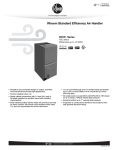
MXN276
Swiftlock Autoclave
80 to 300Litre
Top and Front Loading
Programmable Control
System
4 LINE DISPLAY
CONTROLLER
PROGRAMMING
INSTRUCTIONS
OPERATING INSTRUCTIONS
PRINTER OPTION
INSTRUCTIONS
Powerscroft Rd
Sidcup
Kent
DA14 5DT
United Kingdom
Tel +44(0)208 300 4311
Fax +44(0)0208 300 2247
CONFIGURATION AND ENGINEERING
SYSTEM INSTRUCTIONS
INSTRUCTION
MANUAL
See also Astell Scientific Manual
Part No MXN275(orMXN498)
Part No MXN276 iss03 edition B
Software Issues NSW418
MXN276-3b.doc iss01 ed a
Page 1
CONTENTS
1 Contents
33 Fault System, Temperature
Dropback, Interlock Failure
detection.
2 Introduction , Updates and Issues
3 About this Manual
34 Load Sensed Timing Option
4 Single Program Controller
35 Overshoot and Profiled Overshoot
5 8- Program Controller
37 Internal Printer Option
5 Key to Abbreviations
38 Paper- & Ribbon -Changing
Boost
Printer Paper Problems
6 Keyboard , Instruments
External Printer Option
Interlocks
39 Paper Changing Diagram
7 Setting Clock
40 Chart Recorder / Datalogger
8 Water Filling Manual Fill Models
Option
9 Water Filling Automatic Fill Models
41 Engineering Level
10 Startup, Power On, Opening
42 Engineering Level Configuration
Chamber
45 Engineering Level Engineering
12 Starting , Completing, Aborting
Tests
Cycles
46 Engineering Level
13 Setting Programs - Single Program
models
47 Calibration , Running-Calibration
15 Selecting Programs - 8- Program
49 Special Engineering Functions
models
EEPROM dump , Pressure Switch
Test
17 Cycle Progress
50 Dilswitches
18 Complete Stage
51 Safety-Valve ,Overtemperature
19 Holdwarm
Cutout
20 Cycle Profile Examples
52 Pressure/Temperature correlation
chart
27 Supervisor Level , Program Entry
53 Service Details
29 Program Titles , Maximum
AirPurge Time.
29 Options Cycle Log, Fault Report,
30 Safety-Valve Test Program
31 Selector-Locked program entry,
Manual Program Stage Advance
Program Abort
32 Running Calibration
1
MXN276-3b.doc iss01 ed a
Page 2
SWIFTCLAVE MULTIPURPOSE STERILIZER
PROGRAMMABLE CONTROL SYSTEM
This manual details the Programmable Controller used in this range of Multi-Purpose Sterilizers.
Programming and Controller Operation are covered here but this manual does not advise on dayto-day operation of the Sterilizer itself , setting up for different loads , Loading arrangements, Safety
or Sterilizing advice .
Installation Instructions, Operating Instructions , & Maintenance Instructions are provided in A
separate Instruction Manual
Control System
The Sterilizer is provided with a control system comprising a Keyboard and Illuminated Liquid
Crystal Display. An optional Internal or external printers may be mounted in the control pod, on the
cabinet or freestanding, to record the Sterilization Cycle progress.
Optional Remote Freestanding Chart Recorders and the Astell ‘AutoScribe’ Datalogger are available
matched to the control system to provide independent evidence of sterilizer performance. These are
controlled to run automatically within each cycle.
Instructions for Datalogger & Recorders themselves are covered in additional ASTELL Manuals and
Original Manufacturers Manuals supplied with the equipment .
MACHINE SPECIFICATION AND CONTROL OPTIONS
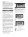
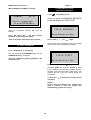
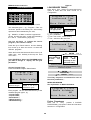
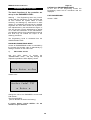
The Control System Display MAY show various items of information when the Mains Power is turned
on , for example...
"SWIFTCLAVE CLASSIC AUTOCLAVE" - denotes Sterilizer Type
“SINGLE “ OR “MULTI” “ PROGRAM” shows no. of programs etc
"SOFTWARE ISSUE ?????? EG;- NSW418P
TIME and DATE of the on-board clock are shown.
Please keep a note of these displays ; You may be asked to quote these to assist the Astell service
dept. if requesting service attention .
A unique SERIAL NUMBER is provided which will enable identification of your
machine for service and maintenance purposes. This is marked on the ELECTRICAL
RATING PLATE at the rear of the case
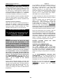
DOCUMENT ISSUES AND DETAILS
Date &
MR no
Issue
Details
Edition &
filename
Details of changes and revisions inc. software issues
and manuals
160605
270407
01
03
A
b
NEW ISSUE
Minor text corrections
2
MXN276-3b.doc iss01 ed a
Page 3
ABOUT THIS MANUAL
This instruction manual is intended for use by OPERATORS , SUPERVISORS, and STERILIZING
ENGINEERS [ or their equivalents ]. The person who is to be in overall charge of the Sterilizer should
familiarise him/herself with the complete system including instructions in the other Astell Stericlave
Manuals.
It is possible to use the machine in a "Basic" manner leaving out the more complicated operating
options.
OPERATOR
The Operator is able to Select the program, Start the Program, Open and Close the Sterilizer door or cover ,
and load the Sterilizer.
SUPERVISOR
The Supervisor has authority to enter Programs, turn on and off options, set the optional clock , etc. These
facilities are only accessible by use of the KEY button on the front panel ]
Program settings ( sometimes called “Profiles” ) can only be entered by the Supervisor.
ENGINEER
The Engineer may set up the configuration of the Sterilizer , select some of the more complicated operating
options, carry out certain tests upon the system, and Calibrate the sensors. Access to the Engineering level
is through the Supervisor level, by use of a PIN Number “password” or alternatively by setting a small
Internal "Programming Switch " which is inside the control pod.
TRAINING
INCORRECTLY USED STERILIZERS MAY PRESENT A HAZARD
For correct use of this Sterilizer it is recommended that Operators, Supervisors, and Engineers are made
fully familiar with these instructions, the other manuals provided with the Sterilizer system, and the functions
and operation and Safety Aspects of this machine .
In less formal establishments, the SUPERVISOR may be an OPERATOR who has adequate authority and
ability to set up the sterilizing process.
The ENGINEER will normally need to have been trained in a relevant discipline , possibly as a Sterilizing
Engineer , be conversant with Micro-Electronic system handling procedures, and be suitably qualified to
carry out the adjustments and changes that may be required.
ASTELL recommend that the ENGINEERING level is not accessed by anyone who does not have an
understanding of the control system instrumentation used in this Sterilizer. The manufacturers reserve the
right to restrict warranty provisions if any part of the Sterilizer is modified , removed, or adjusted without
express instruction by the manufacturer , or in variance with the instructions in this manual .
EC DIRECTIVES
Your attention is drawn to the EC Low Voltage Directive and the E.M.C. directive which affect modifications
and repairs to this equipment. Only parts supplied by the manufacturer as spares or accessories will ensure
compliance with the directives.
3
MXN276-3b.doc iss01 ed a
Page 4
Single Program and Multi-Program Controllers
This manual covers the Single Program controller . It also covers the 10 Program controllers .
The two controller types share most operating features and operations. The Membrane Keyboards and the
method of entering programs are the same and the Displayed messages are appropriate to the control
system type.
SINGLE-PROGRAM CONTROLLER
This has only one program and the Membrane Keyboard is arranged to permit Quick Access to the
parameters to allow them to be easily changed between cycles. The single program is identical to Program 4
of the Multi-program controller and has identical capabilities, with the exception that the programmer can
only be set up to one set of parameter values at a time.
All aspects of these instructions apply unless indicated otherwise. Please disregard any instructions labelled
;-“For 4-or-Multi-programModels ”.
Because there is only one program the “Program Title” feature is not available.
Program Values may be entered by the “Quick-Entry” method or via the Key-Access Supervisor Level
exactly as for the Multi-program system.
It is possible to disable the “Quick-Entry” method & to make Program Parameter Entry only available via the
Supervisor Key .
To do so enable the Selector - lock by setting PROG-SELECT LOCK to ON in the User Configuration level.
4
MXN276-3b.doc iss01 ed a
Page 5
OPERATOR CONTROLS &
SYSTEM TECHNICAL DETAILS
MEMBRANE KEY DELAY
To avoid problems caused by accidental key
pressing, several of the keys have a DELAY
built-in. If pressing the key does not have the
immediate desired effect , maintain pressing
for up to 2 seconds. When the key operation
produces a BEEP noise, then the keypress has
been detected and it is not necessary to keep
pressing.
OPERATOR CONTROLS
DISPLAY LCD
16 Character x 4 - line LCD TEXT DISPLAY
MEMBRANE KEYBOARD
[START] KEY Starts Process
[DOOR] or [Open] KEY Open Chamber door
[STOP] KEY Stops Process ( with “Key “)
[ ]
KEY Increases value
(when setting variables )
[] KEY
Decreases value
(when setting variables)
[ENTER] KEY Enters chosen value
INSTRUMENTATION
CHAMBER Temperature Readout
(Accuracy better than +/- 1.0 Deg C )
"KEY"
gives access to secured
SUPERVISOR and ENGINEERING levels
-Also used for stopping program cycles..
LOAD SENSED Temperature Readout
Shown when load sensed timing is selected)
(Accuracy better than +/- 1.0 Deg C )
Paper Feed KEY Feeds paper
(on certain optional printers;- not case mounted
or external printers)
PRESSURE Readout
( if fitted) With automatic Zero
(Accuracy Better than+/- 0.05 Bar)
"Clock" KEY
Selects Clock & Date-Setting mode
PRESSURE Gauge
Dial Bourdon pressure
gauge at front of machine. (Accuracy Better
than+/- 5%)
POWER ISOLATOR SWITCH
Turns on AC Mains Power to the system
This is a Rotary Switch at the front.
Marked [ 0/1 ] . The “1” position is “ON”.
DISPLAY CHECK FUNCTION
Tests Temp and pressure instruments
In READY state - with door shutPress the [STOP] key – this will momentarily
display current temperature, pressure, etc.
COOL LOCK THERMOSTAT
This is sited behind the cabinet. .
Senses chamber temp. to restrict opening
with hot fluids.See “interlocks” below
OVERTEMPERATURE THERMOSTAT .
This is sited behind the cabinet.
This takes over control of the heater in the
event of water loss or overheating. It resets
automatically when the temperature falls.
OVERHEAT SAFETY CUTOUT. ( optional)
fixed- not user adjustable
This is sited inside the cabinet & cuts out the
control system in the event of excessive
temperature rise ( eg>150C). It is only
resettable
by
manual
operation.
5
MXN276-3b.doc iss01 ed a
Page 6
"Program Profile" . It measures and reacts
to the temperature of the Inside of the
chamber in the same way as the normal
temperature display.
If “LOAD SENSED TIMING” option is fitted
this system senses the Load Temperature
of the Load Sensing Probe, in place of
chamber temperature.
SAFETY INTERLOCKS
PRESSURE INTERLOCK
Preset to <+0.15 Bar this is an electrical interlock
operated by a precision pressure switch
preventing the electrical release of the Closure
lock if the chamber is pressurised.
WARNING- THE COOLING LOCKS CAN
PRESENT A HAZARD IF INCORRECTLY SET.
They should be adjusted by the supervisor, or a
person trained in Sterilizer use & the setting of
safe sterilizer cycles.
OVERPRESSURE CUTOUT
This is preset to 3.00 Bar. If this operating
pressure is exceeded , indicating instrument or
safety valve problems, then the heating is shut
down, a warning shown and a fault condition
generated.
Note that Inspection of the Fault report will show
pressure >300= 3.00 bar
PRESET COOLING LOCK THERMOSTAT This
is a thermostat with Dial & scale calibrated in Deg.
,0-100C, behind the cabinet side cover panel or at
the rear.
TEMPERATURE INTERLOCKS
It measures temperature of the Chamber outer
Wall, providing sufficient thermal mass for a
reasonable match between the Load Temperature
and the Cooling Lock Sensed temperature ,
although the temperatures will not be quite the
same, due to differing thermal inertia.
STARTING- INTERLOCK .
Prevents starting a cycle with a dangerously hot
or pressurised chamber.
Normally the Chamber wall & Cooling Lock sensor
will cool down faster than the load.
PROGRAMMABLE COOLING LOCK.
The STANDARD SYSTEM Operates when LOAD
SENSING option is NOT fitted or NOT selected.
This uses a Cooling-Lock-Temperature set by the
user within the Program Profile which is compared
with the Chamber Internal Temperature Sensor (
the same temperature as appears on the
Temperature display ). When the CHAMBER
temperature is above this "PROGRAMMABLE"
cool-lock temperature the lock is active (engaged)
and Completion is inhibited preventing the door
from unlocking..
“Pressure Sw”
= there is pressure in the
chamber.
Temp>>100C means the temperature in the
chamber is too high.
COOLING LOCKS
There are two Cooling Locks to prevent the
Sterilizer being opened with a Liquid Load under
unsafe conditions.
There are two cooling lock systems ;-They remain
electrically LOCKED until the load has cooled to
a safe handling temperature COOLING LOCKS
operate for FLUIDS and DESTRUCT programs .
The Chamber-Sensor detects the temperature
within the steam space & it will normally Cool
faster than the Load &/or the chamber Wall.
Load Sensed Cooling Lock
( if LOAD SENSED COOLING OPTION is fitted
& selected for that program )
In this case the Cooling Lock Temperature set for
the Program is not compared with the Chamber
Temperature but instead
the Temperature
measured by the flexible LOAD sensor. When
this Load-sensed temperature is falling but still
above
the
"PROGRAMMABLE"
cool-lock
temperature the lock is active (engaged) and
Completion is inhibited , so the door cannot be
unlocked.
PRESET Cooling Lock This is a 0-100 Deg
C. thermostat, with Knob, Dial and Scale .
Temperature sensor is mounted clamped to
the outside of the chamber. It indicates an
approximation to the load temperature.
PROGRAMMABLE Cooling Lock
This is an electronic system set to a
suitable temperature entered within the
6
MXN276-3b.doc iss01 ed a
AS the LOAD SENSING PROBE detects the
temperature within the LOAD itself , it will always
represent the actual load temperature., assuming
it has been correctly placed in the load.
Page 7
Warning
Overpressure + Overtemperature cutouts
The Manufacturers of this Sterilizer accept no
responsibility for damage to the load which may
result in this Sterilizer in the event of a
overheating/overpressure fault occurring for any
reason.
DUAL COOL- LOCK ACTION
The temperature
of ACTUAL LOAD and
CHAMBER WALL must BOTH be below the two
separately-set cool-lock temperatures to allow the
cycle to complete.
OVERTEMPERATURE THERMOSTAT
( All electrically heated models)
The
Overtemperature
Cutout
uses
an
overtemperature thermostat thermally linked to
the Chamber and shuts down the control system
power in the event of overtemperature operation,
which limits heater temperature rise if the system
should fail.
When triggered, Power is cut off to the control
system .
The power will be restored only when the
temperature falls, and the controller will behave as
if the power had just been turned on.
OVERPRESSURE CUTOUT
( option )
The OverPressure Cutout is Precision Pressure
Switch which is sited inside the machine, and is
preset to below the safety valve setting It is
designed to prevent the chamber exceeding the
rated pressure.
The power will be restored only when the
temperature falls, and the controller will behave as
if the power had just been turned on.
OVERTEMPERATURE CUTOUT
Manual reset with alarm ( option )
The Overtemperature Cutout Manual reset with
alarm is Precision temperature Switch which is
sited inside the machine, and is preset to below
the safe operating temperature for the boiler
design it is fitted with an audible alarm.
It is designed to prevent the chamber exceeding
the rated temperature.
An overtemperature thermostat is thermally linked
to the Chamber and shuts down the control
system power in the event of overtemperature
operation, which limits heater temperature rise if
the system should fail.
The power will be restored only when the
temperature falls, and the controller will behave as
if the power had just been turned on.
7
MXN276-3b.doc iss01 ed a
Page 8
CLOSURE SYSTEM INTERLOCKS.
HEATING SYSTEM
The cover is prevented from being opened by a
solenoid locking bolt pin. This Locking Bolt pin
engagement and Cover Position are sensed by
high-reliability Micro-switches. The system cannot
be started unless the closure is fully secured and
locked.
On Direct Heated ,models Steam is generated
from water held in the base of the chamber .
WATER LEVEL CUTOUT
The Electric Heating system uses an electrical
immersion heater and a water level Conductivity
sensors acts at "Filling" level . Water is supplied
from an internal tank and automatic Water Filling
is provided as a function of the cycle.
On TOPLOAD models
The Closure interlock system senses the up/down
positions of the door and the position of 2 of the
sliding bolts that hold the cover shut. The system
also senses precisely the engaged position of the
solenoid locking pin that prevents the handle
being moved.
A second water level Conductivity sensor detects
LOW WATER state in the chamber.
On FRONTLOAD models
The Closure interlock system senses the position
of the door to detec an Open-closed state and
and two microswitches precisely measure the
engaged position of the solenoid locking pin that
both detect the presence of the locking block, and
prevents the handle being moved.
The Cover can not be opened if :A Chamber
Temperature
is
above
Programmed & Preset Cooling Lock setting
B Pressure is above approx. 1.5 p.s.i. /0.2 Bar.(
all Programs )
(The Programmable Cooling Lock Temperature is
set within each program. But the PRESET cool
lock temperature is a single setting applying to all
programs.)
The Cover is also Locked if POWER is OFF.
There is a delay of 30 seconds after pressing the
'OPEN' button before the bolt pin retracts during
which the VENT VALVE is open to atmosphere.
The Cover can only be opened by pressing the
'OPEN' button and waiting for the bolt to unlock.
The OPEN button will NOT open the Cover if
inhibited by the Cooling Locks or the pressure
interlock .
The system will only start and run cycles if the
Cover is fully CLOSED & LOCKED.
It is not possible to pressurize the chamber with
the Cover Unlocked.
8
MXN276-3b.doc iss01 ed a
Page 9
the chamber. The Chamber reaches set
temperature first, and is maintained there
by the controller.
AIRPURGEING SYSTEM
Note; "Airpurgeing" is the Term used here , to
describe an initial period of STEAM FLUSHING at
atmospheric Pressure which uses the steam to
displace the air from the chamber. This may also
be called “FREESTEAMING” .The Program
Profile control provides an adjustable period of
'AIRPURGE' to ensure steam penetration in loads
such as Petri dishes, sample tubes, etc. with large
numbers of trapped air spaces.
When the rising temperature in the load catches
up with the threshold ( eg the Sterilizing Temp),
this is sensed and the Sterilizing Timer System
starts , the Display changing to show
"STERILIZING" with the normal time count-up on
the display.
c]
Load Sensed Timing combined with
PROFILED OVERSHOOT
( may be set in configuration if Load Sensed
Timing option fitted)
The temperature at which this starts is close to
boiling point. This can be adjusted to allow for
altitude effects. ( see calibration section)
STERILIZE TEMPERATURE CONTROL
SYSTEM :
This system gives PROFILED OVERSHOOT.
This system is Active if Load Sensing has
been selected for a particular program.-AND it
has also be set ON in Configuration.
The Chamber Temperature Is measured by a
PT100 precision sensor. This is compared with
the Sterilize Temperature - the “SETPOINT”
stored in the Program Profile, and the controller
acts to keep the chamber at or about that
temperature by switching the heat source. Control
of temperature does not rely on steam pressure.
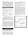
Explanation Of Profiled Overshoot
Alternative systems of Load Sensed Timing
are compromised by the fact that due to
calibration and performance tolerances and
offsets, the temperature threshold which
starts the cycle timing cannot be closer to the
chamber setpoint set for the process than
approx. 2.0 C for reliable operation.
The actual temperature that the control system
tries to attain for will be varied automatically at
different parts of the cycle . This does not require
user attention during the cycle .
The “PROFILED OVERSHOOT” avoids this by
dynamically
changing
the
setpoint
temperature automatically in a series of
profiled stages to match the temperature of
the load heating up. This achieves a threshold
temperature exactly the same as the Sterilizing
temperature
and
a
further
function
compensates for the small temperature offset
between load and chamber during Sterilizing
experienced in normal use. This system is
integral with and dependent upon the use of
the Load Sensing system.
STERILIZE TIMING SYSTEMS :
a] Standard Timing System;This operates if LOAD SENSED TIMING
option is not fitted, or if fitted but it is not
selected for this program. Timing starts
when chamber reaches set temperature,
and terminates sterilization at end of set
period. Temperature and Time are set
within the program.
Heating Failure "DROPBACK :" protection
resets the Sterilizing timer should a fault
cause the temperature to drop below the
Sterilizing setting during the Sterilizing
period. When the temperature rises again
the timing restarts. The standard dropback
level is 2 C below set temperature but may
be adjusted.
The LOAD SENSING PROBE detects the
temperature within the LOAD ( If correctly
positioned ) and ensures that the load
experiences the set conditions for the set time,
without any need for compromises or extended
times to allow the load to "catch-up".
b] Load Sensed Timing System;(Optional Extra)
LOAD SENSED TIMING is selectable (on
or off) within the Program. A "threshold" is
set automatically within each Program at 2
degrees C below the sterilizing temperature
set in that Program. This threshold is
compared with the Temperature measured
by the LOAD SENSING PROBE (the
flexible wandering probe placed by the user
within the load or load simulator).
During the part of the cycle "HEAT-TO
STERILIZE" , the load heats-up slower than
IT IS MOST IMPORTANT THAT IF
LOAD SENSING IS SELECTED IN THE
PROGRAM, THE LOAD SENSING
PROBE IS ALWAYS PLACED IN THE
LOAD
OR CORRECT STERILIZING
WILL NOT TAKE PLACE!
The LOAD SENSED TIMING option also
automatically implements LOAD SENSED
COOLING LOCK for that program.
9
MXN276-3b.doc iss01 ed a
Page 10
COOLING
Cooling action operates whenever appropriate in
the program and only for program types that do
not permit DRYING, eg Fluids cycles At the end of
Sterilize for Liquid /Fluid programs , initially
convection ambient cooling cools the chamber to
a preset pressure threshold. When this
temperature is reached the water is discharged
and the chamber then continues to cool until the
Cooling Lock(s) are satisfied.
POWER ON , STARTING UP,, AND
OPENING THE DOOR
If the COOLING FAN option is fitted the fans
will start at an appropriate temperature preset
to just above 100C, which may be adjusted.
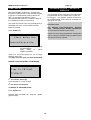
POWER-ON
When power is applied the system goes
through a START-UP PROCEDURE which
displays the system settings. Then it shows .
HOLDWARM
Press [ENTER] key to reset the system.
Some models are designed to operate with
HOLDWARM. This will normally have been built-in
at time of order in the form of increased water
reserve levels.
If the message is “ WAIT…” or “ KEYFAULT” there is a stuck
key on the keyboard – consult service dept.
This should not be confused with a MEDIA
MELTING or WARMING PROGRAM.
These models normally have an increased water
level reserve. The HOLDWARM system can be
turned on in configuration mode, BUT if turned on
on a machine which is not provided with a
increased water reserve, then the holdwarm time
may be limited to 1-2 hours or less.
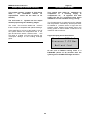
The system then enters the
OPERATOR MODE
giving access to the following ; -
The Holdwarm system is designed to allow
sterilization of MEDIA loads ,with a holding
stage during the cooling process that maintains
the temperature of the load and chamber warm
enough to permit pouring of the melted media. On
a suitable model, The media will be kept warm for
up to 8 Hrs
[OPEN]
Open the chamber closure door
[START ]
Start the selected Program
The Autoclave may be set to operate overnight
with a Media Load, in the knowledge that it will
contain a useable load when opened in the
morning. It is much better though to use the
DELAYED START system to reduce media
deterioration.
The Holdwarm temperature is automatically set to
25C below the Programmable Cooling-lock
temperature as set in the program. Holdwarm ( if
configured to be available) may be selected on or
off within the program profile.
Quick-Select one of the 1st 4
Programs
[ Enter]
Select a program ( 1-10)
[▼] or [▲]
Adjust settings
"KEY"
Holdwarm appears as a stage between
ASSISTED COOLING and COMPLETE
When the Completion Conditions are met as
described elsewhere in this manual the system
then changes to Holdwarm stage,
During Holdwarm the display shows;-
10
access to SUPERVISOR levels
Selects Clock setting
MXN276-3b.doc iss01 ed a
Page 11
HANDLE LOCKED WITH DOOR OPEN
SETTING CLOCK
If the handle is rotated to the “LOCKED” position
with the door open then the lock will engage so
the door cannot be closed until the locked handle
has been released.
Press “CLOCK” key
Clock Setting uses [▼] [▲]or [ENTER] keys to
adjust the Hrs, Mins, Day ,Month & Year. At the
moment when the ‘Enter’ key is pressed after the
Minutes. entry, seconds are reset to zero.
OPENING THE CLOSURE (DOOR)
The door can only be opened when it is safe to
do so. There is a 30 second safety delay
between pressing the "OPEN" Key and the
bolt release which allows the door to be
opened.
Press [OPEN]
The bolt will retract for some seconds. Return the
handle to the unlocked position.
Press the "OPEN" Key; the
display will show
DOOR OPEN , AUTOZERO PRESSURE
When the door is open the system periodically resets the Zero-Point on the Pressure
Measurement System. This message will show
briefly. It does not affect the normal operation of
the machine.
the “xx SECONDS” will count to 30, when the
LOCKING BOLT withdraws for 10 Seconds
DURING THE 10 SECONDS
ROTATE the DOOR HANDLE
The sounder may beep.
The “xx SECONDS” will count up .
ROTATE THE HANDLE
SWING OPEN THE COVER/DOOR.
If the door is not opened within the 10 Seconds
the bolt re-engages and the [OPEN] Key must be
pressed again .
Note;Never lean on the handle or hang anything
over the handle as this will cause the bolt to
stick and will cause early failure of the
mechanism.
11
MXN276-3b.doc iss01 ed a
Page 12
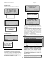
METHOD 2
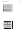
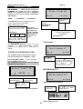
SELECTING A PROGRAM
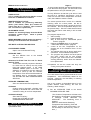
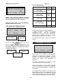
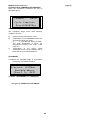
To select ANY one of the 10 Programs
The system must be in the "READY" display
mode with the Cover closed & locked
Press the [ENTER] button
The system will show a “READY SCREEN”
similar to this;(The bottom line has a message scrolled across
the display
The display shows 4of the 10 program TITLES
The examples given ;- eg “ Program 1 Title” etc
are those preset in the factory but will normally
represent a title understood by the user,
1st line= Program Type eg “Liquidload A”
eg “ Media B 1L flasks” would be a typical title.
(These should have been chosen and entered by
the user or commissioning engineer)
nd
2 line= Program Title
( as entered by user or installer)
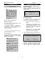
One line will flash to indicate the chosen
program. ( here shown in white)
3rd line= READY stage name & Time
4th line= Scrolling message of what to do next
“Select Program, [Start] or [Open]”
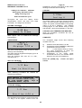
Press the Up or Down buttons and the flashing
line moves up or down the screen to select the
different programs.
Method 1
Quick-Select one of programs 1,2,3 or 4
PRESS KEY, or ……. etc
The Display will change to show the Parameters
and BASIC Settings for the selected program.
( note titles, temperatures and times may vary
from the examples shown here )
When the line hits the bottom the numbers move
up to make room , and similarly at the top.
All 10 programs can be selected
When the required program is flashing press
the [ENTER] button to select it.
The Display will change to show the Parameters
and BASIC Settings for the selected program.
( note titles, temperatures and times may vary
from the examples shown here )
12
MXN276-3b.doc iss01 ed a
Page 13
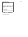
Example Program Types
Classic model
Waste Destruct…135.0 C 30 Min…………
Liquid load A …123.0 C 15 Min…………
Liquid load B …123.0 C 15 Min…………
Glassware …123.0 C 15 Min…………
Waste Destruct …135.0 C 15 Min……
Media Warming …135.0 C 15 Min……
When using the
[ ] , [ ]
or [Enter] routines to change
values or settings
Holding the [] key Pressed
whist simultaneously pressing
the [ ] or [ ] button
will alter the value on the display
in 20’s instead of single digits.
This makes large changes
quicker and easier .
13
MXN276-3b.doc iss01 ed a
Page 14
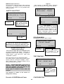
STARTING A CYCLE
COMPLETION OF CYCLE
The Chamber Closure Door /Cover must be
closed and locked
Immediately before the COMPLETE stage is
the EQUALISE STAGE
Here the chamber is given a chance to
equalise temperature and pressure with the
outside world.
Note
If your machine does not
have Automatic Water Fill
option you must fill the
chamber manually- please
refer
to
the
operating
instruction
manual
for
details.
Until this point the chamber
will display the message
After the 60 seconds counts, the system goes
to COMPLETE STAGE
“ PLEASE FILL”
Select the chosen Program Cycle,
The "Complete" stage occurs when following
conditions are met ;-For ALL Programs
PRESS the "START" Key.
1
Pressure in the chamber is less than about
0.15 bar
IF DELAYED START is NOT selected in config.
the Cycle Starts immediately
2
Temperature of the CHAMBER is below
the Programmed Cool lock Temp. or; If
Load Sensed Timing is fitted;- The Load
temperature is below the Programmed
Cooling Lock Temp.
3
Temperature of the COOL LOCK
Thermostat sensor on the chamber wall is
below the set cool lock temperature .
IF DELAYED START IS SELECTED in
configuration then you are asked to enter the start
delay in HOURS Then press ENTER
( see later for details)
If a Printer is fitted then the Printout Heading and
cycle description will be printed.
Until the stage is reached the following screens
show what is delaying completion of the cycle. ;
The Cycle will start.
The controller will perform the program profile
automatically without any need for operator
attention until completion.
Note
Automatic Water Fill option
If your machine has this option, at
Start. it will go to the
“CHARGING
stage .
WITH
“Coolock” is the Cooling Lock Thermostat and
“Pressure” denotes the Pressure switch.
These will not normally show and you may
need to consult your
supplier for advice.
WATER”
Water will be pumped into the
chamber base until it reaches the
upper Running-Level probe , at
which point the cycle will go to
“HEAT TO STEAM”
stage and proceed normally as
described.
14
MXN276-3b.doc iss01 ed a
Page 15
When COMPLETE STAGE is reached
STOPPING A CYCLE
and Cycle Advance
Press [] and [STOP] together.
There is a choice of a MANUAL ADVANCE
to the next stage or a CYCLE STOP
There is a repeated warning “Bip” from the
sounder
Press the Open Key , the Door Unlock
proceeds as previously described.
Press either [
after 30 seconds, Unlock and Open closure.
] or [ ] keys
Not all stages may be advanced. The cycle Stage
will move on if this is possible & available.
To Stop Holdwarm
Press [DOOR] key ie [open] key
This will terminate HOLDWARM stage and the
COMPLETE display will appear.
Open the chamber by pressing [OPEN] in the
normal manner.
Press either [
] or [ ] keys
Choosing STOP will cause the CYCLE to abort
but the sterilizer will continue to operate until the
chamber and load have been made safe. This
requires that the cycle end /cooling stages are
completed.
Choose No = to go back to normal running
operation.
NOTE;If left in this state without any actual entry,
after a period of time the system will
automatically go back to running.
15
MXN276-3b.doc iss01 ed a
Page 16
START DELAY
PROGRAM CYCLES - DETAILS &
DISPLAYS
DELAYED START- If selected in Configuration
this allows a delayed start of the selected program
to permit it to automatically start-up after a set
time , for example This allows a cycle to
automatically start itself and complete in time for
the Laboratory to open in the morning.
The CLASSIC models covered by this manual are
programmable and the details of the cycles can
be changed , the program profiles are set from
the SUPERVISOR LEVEL and not accessible for
change by the user .
The actual Cycle-Start Time may be delayed by a
selectable time up to 18 hours after the Start
Button is pressed.
For Each CycleThe Sterilize Time,/Temperature, Airpurge
Time , Sterilize period, & other variables are
set to provide the desired Cycle Profile.
Press START Key
Please note that correct Sterilization is dependent
upon the program PROFILE being suitable for the
load and processing required.
Press
Up/Down
to
set
Press ENTER to
Start
Delay
in
Hours
Initiate cycle/Start
There is a 10 second period for you to begin
setting a delay time.
If no time is set the cycle will start immediately
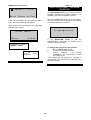
DURING DELAYED START COUNTDOWN
2nd line shows time to go
Cycle will start in 1 hr 46 minutes
4th line shows current time
TO ABORT A DELAYED START
Press STOP button
Delayed start countdown will stop and system
goes to Ready.
16
MXN276-3b.doc iss01 ed a
Page 17
DETAILS OF CYCLES
Throughout each cycle the LCD display shows
Temperatures, Times, and other cycle stage
information.
STERILIZE PERIOD
LOAD HEATING TO TEMPERATURE
and
OVERSHOOT BOOST options/settings
See LOAD SENSED TIMING & OVERSHOOT
BOOST
These particular cycles have a slow pressure
release and NO drying facilities.
When the cycle has been started the heating
begins. A cycle cannot be started with insufficient
water.
Please see AUTOFILL section if your machine
has Autofill option installed
HEATING TO STEAM
The temperature and pressure will fluctuate within
+/-1 Deg C as the system controls at the set
temperature. The time counts down in Min & Secs
showing the Sterilize time remaining.
AT THE END OF THE STERILIZE PERIOD THE
COOLING STAGES START
When approx. 95-99 C is attained the Airpurge
Period begins....( this temp is adjustable )
.
COOLING stage A
AIRPURGE
At the end of Sterilize period COOLING stage A
begins.
The Time counts down in Min & Secs to show
Airpurge Time Remaining.
( See PULSAR Pulse Freesteam section)
(An Airpurge time of 7 minute is the minimum
advised for solid loads such as empty glassware
but longer Airpurge times are usually requred.).
If ASSISTED FAN-COOLING is fitted , the
cooling fans will start at a temperature of
typically 100-105C . This level is preset in the
CALIBRATION of the machine & may be adjusted
HEAT TO STERILIZE
The chamber and load cool until the pressure has
fallen to a threshold level of typically 70 mBar
above ambient.
When Sterilizing Conditions are reached , ie
steam saturation in the load , defined by the
elapsed Air Purge Time, the Sterilize Period
begins .
The cooling then moves on to stage B
COOLING Stage B
The chamber and load cool until the complete
conditions are met.
17
MXN276-3b.doc iss01 ed a
Page 18
HOLDWARM
The Holdwarm system is designed to allow
sterilization of MEDIA loads ,with a holding stage
during the cooling process that maintains the
temperature of the load and chamber warm
enough to permit pouring of the melted media.
Holdwarm appears as a stage between
ASSISTED COOLING and COMPLETE
The 2 COOLING LOCKS prevent opening until
the load has cooled to a safe handling
temperature.
The media will be kept warm for up to 48 Hrs .
PRESET Cooling Lock This is the 0-100 Deg
C. thermostat, at the back of the case. It
measures temperature of the outside of the
chamber indicating an approximation to the
load temperature.
The Autoclave may be set to operate overnight
with a Media Load, in the knowledge that it will
contain a useable load when opened in the
morning…. or later in the day.
PROGRAMMABLE Cooling Lock
This is an electronic system set to a suitable
temperature entered by the Supervisor within
the "Program Profile" . It measures and reacts
to the temperature of the Inside of the
chamber.
The Holdwarm temperature is fixed to 25C below
the Programmable Cooling-lock temperature set
in the program.
If “LOAD SENSED TIMING” option is fitted this
senses the Load Temperature instead of
chamber temperature.
When the Completion Conditions are met as
described above, if selected, the system goes
instead to the HOLDWARM stage
Holdwarm may be set on or off within the program
profile.
COMPLETE Stage
If HOLDWARM is not selected ;
( see HOLDWARM, next item )
When the "Complete" conditions are met display
shows ...
TO STOP HOLDWARM
Press [DOOR] key
This will terminate HOLDWARM and move to the
COMPLETE Stage
( see previuous item)
Then Open the
manner.
You may now Open closure as normally
Press the [Open] Key , after 30 second. delay,
Unlock and Open closure.
Note
To silence BIP noise warning without opening
door press OPEN button but do not open door
and after that BIP noise is muted
18
chamber in the normal
MXN276-3b.doc iss01 ed a
Page 19
stage is different
AUTOFILL OPTION
The Autofill option comprises a water tank and c
float switch controlled inlet valve. It also has a low
water float switch to detect water level supply
problems.
If fitted and configured ON the system
operates as described but when the cycle
starts it fills with water supplied from the
tank a pump up to the “RUNNING LEVEL” set
by the upper conductivity probe in the
chamber.
The * shown here is replaced by a
denoting state of the exhaust valve.
symbol
This is either “” BOX symbol
- This means the Valve is closed
or
“Three short lines” symbol “ ”
This means the valve is open.
During this period the system displays ;-
The valve cycles on and off throughout the
Airpurge period to achieve the PULSED
FREESTEAM operation.
Explanation Of Pulsed Freesteam.
If this goes on for too long there may be a
problem with water level detection, water
quality, or thepump and valvework. Please
consult your service agent.
PULSAR FREESTEAMING is the Astell
name for this patented system.
With this arrangement the controller turns the
VENT STEAM EXHAUST VALVE on and off in a
programmed manner, to permit steam to escape
in bursts, building up pressure slowly during the
"closed" period and releasing this to atmosphere
during the "open" period. This causes the
Boundary layer to move up and down within the
container, and the pressure reduction during the
"open" period is fast enough to cause great
turbulence within the chamber, breaking up the
boundary layer, and drastically increasing the rate
of diffusion of steam into the container and load.
At the end of this it goes to the stage
“HEAT TO STEAM “
If the water supply is affected and the tank
level falls the system will detct this and
indicate;-
The Open-Closed Cycle is factory-set to Typically
1 min open, 1 min closed .
Seek the source of the problem before calling
for service as the usuakl cause is that
someone has turned off the water!!
PULSED FREESTEAMING Option
The PULSAR ( pat) system is a Astell patented
system for improving steam penetration into
difficult loads without requiring the complication of
vacuum pumping systems.
When this option is fitted and selected within a
program , the behaviour in the AIRPURGE
19
MXN276-3b.doc iss01 ed a
Page 20
Steam Output Quench-Cooling
Air Ballast COOLING
This is an optional extra
This is an optional extra
This system requires a supply of Cold mains
water ( see installation manual for
requirements which are the same as for
AutoFill)
This system uses either an additional air
compressor or a building supply of
comprtessed air,.
A regulator and filter
supply the aair to a solaenoid valve which
introduces it to the chamber during cooling.
The Cold water is injected into the output
exhaust pipe during the Steaming stages.
The Compressed air is metered into the chamber
and the pressure controlled by themicroprocessor
to establish a pressure which is higer than the
pressure within Sealed Fluid Bottles during the
cooling phase to allow sealed containers to be
used and reduce boilover.
The water flow cools the steam and ensures
that the output is compatible with plastic drainage.
If the water flow is too low or the supply is cut off
the system detects the temperature rise in the
pipe and shuts the steam exhaust valve, - this
will result is a failed cycle but will prevent the
consequent damage to the building drainage
pipes.
A typical display would be as below
At the end of Ballast cooling there is a
EQUALIZE period of 90 seconds then the
system goes to COMPLETE stage as before.
20
MXN276-3b.doc iss01 ed a
NOTES AND SUGGESTIONS
On Programming
Page 21
If one program has been set as a Media Warming
Cycle then with this program, You still need to set
the parameters to suit your desired cycle.
LIQUID CYCLE
This is suitable for processing Media or other
fluids etc in UNSEALED containers.
The key difference is that this cycle will not heat
the load to a “sterilizing” temperature such as
121C but will work with a temperature set below
100C, but suitable to melt the media.
WASTE DESTRUCT CYCLE
This is suitable for processing laboratory
waste;- petri dishes, tubes, jars, bottles etc.
These must be in a shallow open container
and not sealed in a plastic bag.
The actual process does involve the chamber
reaching 100C for a short period but this is
essential to ensure the steam purges the air from
the chamber. then the temperature drops to the
set process temp . Since the load thermal inertia
will cause the load to heat slowly it will not itself
reach 100C.
GLASSWARE CYCLE
Suitable for sterilizing Empty Unsealed Glass
containers, animal cages, metal or plastic
containers, etc.
The program sequence is:1
start normally,
2
Heat Chamber to approx 95-99C
Stay at that temp for AIRPURGE period
as set in program
3
Reduce CHAMBER temp to typ 80-95C,
= MELTING TEMP as set in program
4
control at the Set Temperature for the
duration set on the Sterilize Timer .for the
program
5
the chamber does not go above 100C which
would be a normal sterilize temperature.
6
The program will perform the timed period
and enter cooling just as with another
program type. there will not be a Chamber
Venting (blowout) action since the chamber
is not pressurised
MEDIA WARMING CYCLE allows the heating ./
melting of media without full sterilization
SEE NOTE LATER IN THIS SECTION
LOAD SENSED TIMING
Option- see Load Sensed Timing
STERILIZE TIME ;
Set the Sterilize time to the desired
exposure time.
Allowance For Extra Time For Load To Reach
Sterilize Temp
These Loads normally require an allowance
for extra time for heat-up as they suffer
from high thermal inertia .If the LOAD
SENSED TIMING option is not used an
allowance is needed for the time taken for
the load to catch up with the chamber
temperature. Extra time should be added to
the Sterilize time to compensate. Please
see SETTING UP AND COMMISSIONING
SECTION
7Completion etc are as normal and obey the
cooling lock system as before.
STERILIZE SETTING WITH
LOADSENSE TIMING OPTION FITTED.
The Load Sensed Timing system detects the Load
temperature , and automatically allows for the
time-lag caused by the load delay in reaching
sterilize temperature.
STERILIZE TEMPERATURE;
Set to the desired sterilize temperature .
Set up the system as described above for the
system Without Load Sensing, but with the
following detail changes ;-
COOLING
Cooling mode is automatic- chamber cools
naturally to threshold then vents water and
continues cooling to cool lock temperature.
a) Set the STERILIZE TIME to the Actual
DESIRED STERILIZE TIME.
-The Chamber Temperature will heat to the
Set Sterilizing Temperature, and will display
a message "LOAD HEATING TO
STERILIZE".
The Sterilizing timer is
stopped.
When the load reaches Sterilizing
Temperature the Sterilizing Timer will
START , and the cycle will proceed. ( It is
not necessary to note down any value or
time .)
COOLING LOCK(S)
Set to 80C for safety.Please see SETTING UP AND
COMMISSIONING SECTION
MEDIA MELT/ WARMING CYCLE
This system allows media MELTING / WARMING
cycles below 100C.
21
MXN276-3b.doc iss01 ed a
Page 22
GENERAL PURPOSE CYCLE
LABORATORY FABRICS, LAB COATS,
etc
For sterilizing Laboratory Glassware,
containers, cages, etc,
For best results these items should only be
sterilized in a purpose-built Sterilizer with a
specific Fabric/Textile cycle such as the ASTELL
STERICLAVE range of sterilizers
This Autoclave is not designed to process Fabric
Loads, Unless as an occasional or emergency
“Make-Safe” function as part of a decontamination
process.
These can be sterilized using the same cycle as
the DISCARD load described above. AirPurgeing
as short as 8 min may be required for simple
loads where the steam can penetrate the load
easily. Small bottles, tubes, etc may need
AirPurgeing up to the maximum allowed time
Whilst it is possible to process unwrapped simple
and light fabric loads, they will come out saturated
with water and sterility will be compromised,
since there is no Drying function.
The Cooling Lock Temperature is of less
importance if the load does not contain liquids.
The chamber will cool down more quickly than the
load, so if the Programmable cooling lock is set to
99C the limiting factor will be the Preset Cooling
Lock, This must be left set to suit the worst-case
Liquid load if the autoclave is used for liquids.
Such items must always be loaded loosely and
not folded or wrapped to allow easy steam
penetration to all sides , but even so sterilization
may not be perfect.
If not used for liquids at all , Preset Cooling Lock
may be set to 99C.
Use the same cycle settings as for a Makesafe /
Discard load as described above, with maximum
AirPurge time.
22
MXN276-3b.doc iss01 ed a
Page 23
Also Beware the effects of containers that trap
water- see earlier section re “LOADING”
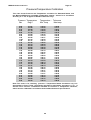
SETTING UP AND COMMISSIONING
SELECT STERILIZE TEMPERATURE / TIME
This Machine comes with the programs preconfigured and parameters set to typical program
profiles to suit appropriate loads. The Sterilize
Temperature and Time are adjustable from the
front panel by access to the SUPERVISOR level.
The
U.K.
Medical
Research
Council
recommended the following time/temperature
relationships for the achievement of sterilizing
conditions:-
Typical Factory Settings ( as Delivered )
121
121
134
15
30* *
80
no
15
7
99
X
30
7
80
no
Temperature Tolerance
Please note that during sterilizing the temperature
will normally cycle up and down over a range of
approx +/- 0.7C around the set sterilize
temperature. Where temperature is specified as “0 +??” adjust the temperature as shown here.
AIRPURGE - Suggested settings ranges
shown belowNote that the MINIMUM airpurge time is
typically 7 minutes and is preset in calibration
to ensure adequate performance.
Specified
Settings
134C -0+4
3 mins
126C -0+3
10 mins
121C -0+3
15 mins
115C-0+3
30 mins
SOLID LOADS/Glassware
Set the Airpurge period to 7 – 10 minutes ..
LIQUIDS ;Set the Airpurge period to 7 – 45minutes* *
WASTE DESTRUCT ;Set the Airpurge period to 7 - 45minutes
3 min
10 min
15 min
30 min
Lower temperatures or shorter times may have to
be used to prevent degradation of bacterial growth
media. This may be adequate for culture purposes
, but does may not constitute full sterilization. The
manufacturer of the media will usually specify the
sterilizing temperature.
DESTRUCT
GLASSWARE
FLUIDS
PARAMETER
STERILIZE
TEMPERATURE
STERILIZE TIME
AIRPURGE TIME
COOL LOCK TEMP.
138
129
124
118
Minimum
Sterilize Hold
Time
134
126
121
115
Maximum
Sterilize
Temperature
Minimum
Sterilize
Temperature
It is not suggested that you use these programs
as they are. It will almost certainly be necessary t
adjust one or more of the parameters to suit the
laboratory preferences and requirements. As a
minimum the PROGRAM TITLES should be set
up to
represent
names that can be
remembered in the lab.
**
**
AIRPURGE TIMES
may be called “”FREESRTEAMING TIME “”
Airpurge times longer than 35 minutes on a
unloaded or lightly loaded chamber or open
load
containers which can collect and trap
condensate from draining back down to the
chamber base- have the potential of boiling dry
cause excessive heating in the condensate bottle
and potential hazards from steam and
condensation. Please ensure loading matches
the selected cycle.
23
Recommended
Program
Settings
135C or 136C
3 mins
128C
10 mins
123C or 122C
15 mins
116C
30 mins
;
MXN276-3b.doc iss01 ed a
Page 24
It is possible to set-up the cooling locks in a
simple way as shown below, but they are ideally
set using a thermocouple ( t/c) and digital
thermometer with the t/c sealed inside the
chamber immersed in the liquid load. This is
quicker and more accurate but is normally carried
out by a service or commissioning engineer
requiring use of a Thermocouple entry adaptor,
and details are in the Service Manual.
CALIBRATION
This machine has been factory calibrated to
NAMAS standards by Astell Scientific. It is often
the case that a machine must be calibrated on site
to comply with local requirements, and this can
be carried out by Astell Engineers. Details of full
on-site Calibration techniques are in the Service
information provided to agents or in calibration
Instructions available to download on request.
To set the Cooling lock without a thermocouple, a
laboratory liquids thermometer reading to 100C is
required.
Load the chamber with the desired load, and
make a first approximation of
cooling lock
temperatures . 80C is suggested for both the
Programmable and Preset settings. Start the
cycle and allow it to complete. Very Carefully
remove the load, using insulating gauntlets and
suitable face protection in case the load is too hot.
Immediately measure the temperature of the liquid
in the load container that was nearest the centre.
Note that calibration requires specialist calibrated
reference thermometers and pressure gauges ,
and an understanding of sterilizer calibration and
thermocouples.
Autozero Pressure Calibration
When the door is open the system periodically recalibrates the “ZERO” setting of the pressure
transducer. A brief warning message may appear
during this period. It does not affect any other
operations and requires no user intervention.
SETTING COOLING LOCKS
Record this temperature and compare it with the
desired opening temperature (80C suggested ).
The measured temp. is likely to be higher than the
desired temperature. Adjust the Programmable
and Preset settings as required and repeat the
cycle with the same load , open, measure and readjust if required. Continue until the desired
Cooling Lock release temperature is reached.
The Cooling Locks are present for all
cycles including Solid loads and
Glassware programs
WarningCooling Lock settings are part of the safety
system and are the responsibility of the
owner/ user of the machine . they must be set
to provide safe conditions for unloading the
chamber. Setting is the responsibility of the
person with Supervisor access . Do not leave
the settings as delivered by the factory. .
SETTING COOLING LOCKS
SENSED TIMING OPTION
with
LOAD
COOLING LOCK TEMPERATURE
With LOAD SENSING SELECTED
The LOAD SENSING option automatically
changes the PROGRAMMABLE COOLING LOCK
to a mode which detects the Temperature of the
Load itself via the LOAD SENSING PROBE ,
instead of sensing the temperature in the Dummy
Load..
To allow for control over cool lock operation
the Programmable Cooling Lock temperature
can be set to ( say) 99C for these loads but
the Cooling Lock thermostst will override the
settings. A compromise can be reached with
the PROGRAMMABLE cool lock stat set to
(say) 95C and the PROGRAMMABLE cool lock
value
set to release at the desired
temperature.
Set the PROGRAMMABLE COOLING LOCK
TEMPERATURE to the actual Temperature of
the LOAD at which the Cooling Lock is to
RELEASE and allow the door to be opened. It is
advisable to err on the Cooler side , for safety.
During cooling inside the chamber, the load cools
slower than the chamber temperature and gives
up heat to the chamber walls. This means that the
chamber will reach 80C before the load so (
unless load sensed timing is fitted + on) the
cooling lock setting will need to be BELOW the
temperature
Because the cool lock senses the actual load
temperature there is no compromise , estimation
or guesswork required over the release
temperature.
24
MXN276-3b.doc iss01 ed a
Page 25
SUPERVISOR LEVEL
PIN NUMBERS
- There are two security pin
NUMBERS for normal use and a specialist
number for exceptional use by a calibrating
engineer (in the event of factory recalibration
requirement.)
USER
----
ENGINEER --- ADVANCED
The USER PIN number is adjustable to user
choice. This is done in the USER
CONFIGURATION section.
USER PIN
Initial Factory set to 157
New Setting
"No" to Skip to next
section
SUPERVISOR
OPTIONS
The initial
PIN NO remains
as factory-set
unless changed
by the operator
in Supervisor.
Level
ENTRY AND EDITING
PROGRAMS
See page xxxx
You may choose to
Record any new setting
here
Fault-Report
The ENGINEER pin no is fixed. It is made
available
to
approved/authorised
service
engineers and agents and to End-Users on
request.
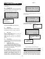
ACCESS TO SUPERVISOR LEVEL
The Chamber must be Closed and Locked
This will normally be in “REAFDY” stage
Press No=
to move on
Press the [KEY] button - when prompted ,
Enter the USER PIN number .
The display starts off at 197 , use the keys to
change to the User PIN no .
Press "Down" to
decrease value,
"YES" to Enter
Programs
Press =Yes
to Print or Show a copy of
the report for the last fault
that happened . See
FAULT REPORT section
WATER QUALITY?
Press "Up" to
increase value,
Water conductivity indication.
Press "Enter" to
select that value.
Press No=
to move on
This gives access to the Supervisor options;-
Press =Yes
to show the
quality figures
Water Quality Figures
25
water
MXN276-3b.doc iss01 ed a
The two figures show the relative water electrical
conductivity ( in arbitrary units ) in a form that
Astell can use to advise you over possible water
quality problems.
Page 26
Only appears if Recorder Power Switching
option is incorporated and configured to operate.
SAFETY VALVE TEST
Press No=
to move on
Press =Yes
The Next Program
Run Will Perform The
SafetyValve Test
Press =Yes
to “Toggle” ON or OFF the external
recorder power switching incorporated
with Astell Recorder Options or the
VOLT-FREE contacts used to control
ASTELL Datalogger options. permits
changing of Charts, testing, etc.
Press =Yes
to run test
PROGRAM MENU
Only appears if Printer Option is fitted
Answering “YES” will force the NEXT program
cycle to use a preset set of parameters
specifically for testing the safety-valve. This
runs at excess temperature and pressure.
Do Not Use except for
Safety-valve testing.
Press No=
to move on
You must first have Set up the Sterilizer with
no load, and close the cover. THEN Go to
Supervisor mode, move through to SAFETYVALVE TEST? Enter YES ,then YES to the
“CONFIRM?” question .
Press =Yes
Prints a simple Menu of
the programs in this
machine , as currently set.
TEST PRINTING?
Then step through & quit Supervisor Mode.
The display shows a warning about Safety Valve
Testing, and then changes to “READY “ mode ,
with a warning noise. Press the START Key to
start the safety-valve test cycle.
NOTE ;- ESCAPE ROUTINE…If this mode is
entered in error Press the OPEN key , and
open the chamber. This will reset to the
previous settings for the program.
If the cycle is started in error abort the
program.
Press No=
to move on
Your attention is drawn to the section on
Safety-Valve Testing .
CONFIGURATION
Recorder /LOGGER Manual Power
26
Press =Yes
to Print a simple
printing – quality test
on the optional printer
(if fitted)
MXN276-3b.doc iss01 ed a
Page 27
USER CONFIGURATION
The “User” section of Configuration is accessible
to the Supervisor, including changing or setting
the USER PIN NO. For details of complete
Configuration see later section
Press No=
to move on
Press =Yes
to enter USER CONFIG.
Mode
See
CONFIGURATION
section - later on
CYCLE LOG
( not available all versions)
Press ”Yes” to display the log of the last cycle
If the Printer is fitted then the log will be printed. If
not it will display on the screen and requires
keypresses to step through the report one line at
a time so that it may be written down.
The report comprises a list of the cycle details and
the times at which the following stages started
and ended
Start cycle
Start Airpurge
End Airpurge
Start Sterilize Period
End Sterilize Period
Complete
It also includes faulty cycle indication.
27
MXN276-3b.doc iss01 ed a
Page 28
PROGRAM ENTRY
LOADSENSED TIMING ,
Program Selection;-
Note- this is Only present if load-sensed timing
option is fitted and has been turned on in
configuration.
The display shows 4of the 10 program TITLES
The examples given ;- eg “ Program 1 Title” etc
are those preset in the factory but will normally
represent a title understood by the user,
Set On or Off
as appropriate.
Press "Enter"
to move on
st
1 line= Program Title
2nd line= parameter
3rd line= Yes or NO , current setting
4th line = set Yes or No and Enter
eg “ Media B 1L flasks” would be a typical title.
(These should have been chosen and entered by
the user or commissioning engineer)
One line will flash to indicate the chosen
program. ( here shown in white)
Press the Up or Down buttons and the flashing
line moves up or down the screen to select the
different programs.
When the line hits the bottom the lines move up to
make room , and similarly at the top the lines
move down
=<
Press to
move back and
re-enter
this
value
Press [ENTER] to Select the PROGRAM which
you wish to change or display the set cycle
parameters
<<=
Press to
move
back
one step to the
previous entry
These key entries allow the correction of
mistakes by stepping back and amending your
entries as required
Choose Program Type
Press the desired Program Select Button
ENTER
followed by
=< ENTER <<=
Press "Enter" to
select that type.
ENTER
This Entry sequence is continued for each of
the other parameters;...
MEDIA HOLDWARM
See explanation on Media Holdwarm.
Press or to
scroll thro types
Each program can be associated with any of the
available program types , eg
“Liquid loadA",
“Liquid loadB",
"Glass/Solids ",
" Waste Destruct “
" Media Warming ".
Pulsar Freestream
Note- this is
Only
present if PULSAR
FREESTEAM ( pat) option is fitted and has been
turned on in configuration.
28
MXN276-3b.doc iss01 ed a
Page 29
List of Parameters
Other Options
Where other specialist options such as
modes for HTM20/10 Compliance are available
they will appear next in this sequence
Next the system allows you to set NUMERICAL
VALUES Instead of On or OFF
PARAMETER
Max.
value
Min
value
Steri, temp
STERILIZE TEMPERATURE
138C
50C **
Steri, time
STERILIZE TIME
1650
min
0 min
PURGE TIME
60min
3 min
Cool Lock
COOL LOCK TEMP.
99C
30C
SET STERILIZE TEMPERATURE
Press or to
adjust in Deg C
Note that for a selected MEDIA WARMING
( MEDIA MELTING ) program the Sterilize
temperature value
sets the “PROCESS”
temperature at which the chamber will be held for
the set time, { because we are not actually
sterilizing, but just warming or melting } .
Press "Enter"
to select that
value.
eg Melt and hold at 80C.. requires this to be set
to 80C
ENTER
followed by
=< ENTER <<=
PROGRAM TITLE ENTRY
This Entry sequence is continued for each of
the other parameters;...
to go BACK
1 entry
to go BACK
2 entries
Press "Enter"
to move on
At the end of the Program Parameter Entry
section the user is given the choice of entering or
changing an alphanumeric “TITLE” for each
program . The TITLE is displayed or printed to
enable easy reference and identification of
programs.
The Factory set titles may be changed to titles
that suit the actual loads & processes.
Each TITLE consists of 16 characters which are
entered in sequence by using the "UP" & "DOWN"
keys to scan through the alphabet, numbers, and
punctuation.
The existing Title is shown on the top line, and
each Character of the title is selected in turn and
flashes when selected. . The character is changed
using the UP & DOWN keys. Press the "ENTER"
key to save that character and move to the next.
29
MXN276-3b.doc iss01 ed a
Page 30
SELECTOR-LOCKED PROGRAM
SELECTION
The SELECTOR LOCK may be set to prevent the
Operator changing the Program selection. It is
enabled in the User Configuration section .
When the OPERATOR tries to select a Program ,
then the Program will not change and the display
will indicate Selector is “Locked”.
If the Title is less than 16 characters the balance
of the 16must be made up with spaces.
When all have been entered there is a short delay
while the title is stored.
If the SELECTOR LOCK is ON the
SUPERVISOR must select the Program which
will be run by the Operator.
Press No= to return to
“READY” STAGE
To Change the program for the Operator
1
Go to SUPERVISOR LEVEL
2
Answer YES to Enter Program?
3
Select
Program , step through
parameters . You may change or leave
them as they are.
This program will then be the one available toi
the operator until this process is repeated for a
different program.
Press =“Yes” to
Enter
More
Programs
30
MXN276-3b.doc iss01 ed a
Page 31
USER CONFIGURATION
Some basic Configuration items are available to
the Supervisor.
A
Prog-Sel Lock
This is the Select-Lock . If ON only the supervisor
may select Programs, via the KEY button & Pin
No
See "Selecting a Program " for details.
Select YES to change the user Pin no to one of
your own choice.
Use the Up and Down
arrows to select
On or OFF
for this Config Item
Use up/ down buttons to select Pin no .
Now WRITE IT DOWN!!
Press ENTER
save
& Move on
The Rest of the USER Config. items are:B
ABSPRESS
Absolute Pressure Display in stead of Guage .
Ie atmospheric Pressure = approx 1.0 Bar abs.
C
US-Format
Selects
United States format for date and
pressure in Pounds-per-sq.-in
If set to ON date = 14/08/97 = 14th August1997 ,
& Bar.
If set to OFF date = 08/14/97 = 14th August1997 ,
&PSIG
Select YES to go to
Engineer Setup Mode
See section “ Engineer
Setup “
D
5C++ Boost?
If set to ON the Profiled Overshoot Boost system
is enabled on ALL programs where Load Sensed
Timing is selected.
Press NO
to return to
“READY” Stage
E
SPARE, NOT USED
Some versions have BeepInhibit ?
If set to ON this inhibits many of the BEEP
sounder indications for those situations where the
sound may be an annoyance . Warning sounds
and Key-beeps are maintained
End of ENGINEER SETUP SECTION
FAULT DETECTION SYSTEM
F
StartDelay
The Start Delay allows a delay time to be entered
each time the cycle is started, from 1-18 hours.
For Example, this allows a load to be placed in the
chamber in the afternoon, which will start
automatically before start of work next day.
If set To “ON” , Start delay is active on all
programs whenever the “START” Key is pressed.
TEMPERATURE DROPBACK
If the heat source fails during the course of the
STERILIZE period then the chamber temperature
will drop. When the Temperature falls more than a
set value-, typ 2.0 C, below the SETPOINT
31
to
MXN276-3b.doc iss01 ed a
temperature the Sterilize Timer is reset and the
system "idles" until the temperature recovers, at
which point the timer restarts. This is intended to
prevent Completion with Unsterilized loads in the
event of Steam failure or Electrical Partial Supply
Failure.
Page 32
The ?? counts up to 15 or 20 during this period
the chmber is exhausted to atmosphere. If at the
end of this the pressure switch is still reading
pressure a FAULT is detected and the system
goes into Fault report mode.
If the problem disappears in this period the
system self- corrects back to normal operation.
FAULT REPORT
Faults are often intermittent and the system
reports the condition of the interlocks when the
fault happened. This report is provided on
standard models by a series of displays on the
LCD display. These should ideally be read by the
operator and written down by the operator
following the instructions on the display. If a
Printer is fitted it will print out the FAULT REPORT
automatically.
Machine function & Display reverts to normal
when fault ceases, temperature rises again and
conditions are restored.
The threshold level is adjustable & set in
Calibration.
The report on the last fault that occurred is held in
maintained memory. It is accessed via the
Supervisor Mode described earlier.
Please also See Load Sensed Timing
The report should be retained and made
available to the Service Engineer to make
diagnosis possible.
INTERLOCK FAILURE
The safe function of the Sterilizer is governed by a
series of electrical and mechanical interlocks
which are continually monitored and checked for
correct operation by the microcomputer controller.
In the event of a fault in this system that is
detectable by the computer an INTERLOCK
FAULT is reported.
Fault Report Information
The fault report supplies a snapshot of the
machine at the time the fault occurs .
A document on how to
diagnose and
interpret this is available for download on
request.
INTERLOCK FAULT
This shows that one or more of the safety and
door interlocks are out of adjustment and require
the attention of a qualified engineer.
PRESSURE SWITCH FAULT
The Safety Pressure switch detects pressure
innthe chamber above about 0.15 Bar. And is
responsible for
preventing access to a
pressutised chamber. It is sensitive and in the
event of drift in setting, age or misuse may fail,
normally failing to the “safe” mode.
If the pressure switch detects pressure at the start
of the cycle when there cannot be pressure in the
chamber then it will enter a test mode.
This displays as
32
MXN276-3b.doc iss01 ed a
Page 33
During the “Load Heat >>” temp.” stage , the
Chamber temperature is artificially boosted +2 C
above the set sterilizing temperature .
LOAD SENSED TIMING
( Optional Extra )
The load sensor monitors the load as the
temperature approaches the set Sterilizing
Temperature .
All Sterilizer loads have Thermal Mass. This
means that the load will ALWAYS heat up slowly
compared tp the Sterilizer chamber. If this is not
allowed for in timing or the profile, the load will not
be subject to correct sterilizing conditions, ie it will
be exposed to the set temperature for too short a
time. Load Sensed Timing avoids this problem.
When the load temperature equals the set
Sterilizing temperature the boosted chamber
temperature is reduced to just +0.3C above the
set Sterilizing temperature.
INSTRUMENT LOADS
Most “Instrument” loads are of fairly large surfacearea/mass ratio, and will heat up following the
chamber temperature fairly closely without the
need for load sensed timing. Where a load is
suitable for the insertion of a sensor, and the
thermal mass is high compared to the surface
area, then Load Sensing can be used.
MEDIA LOADS
Bottled-Fluid loads are of high mass and suffer
from the slower heat-up . Load Sensed Timing is
entirely suitable, and extremely effective in
reducing this problem.
If correctly positioned the LOAD SENSING
PROBE detects the temperature within the LOAD
and so will ensure that the load experiences the
set conditions for the set time, There is no need to
compromise or extend times to allow for the load
to catch-up in temperature with the chamber.
.........”
DESTRUCT/DISCARD / MAKESAFE LOADS
These are best sterilized WITHOUT Load Sensed
Timing. The Profile should provide sufficient
tolerance to ensure the cycle specification is
achieved.
SPECIAL LOAD SENSORS
The Load sensor provided with this system is a
5mm
Dia
armoured
flexible
type
“K”
thermocouple. This may be too stiff or solid to use
for some loads.
When Fitted as an option ( No AAR014) , It must
also be enabled in the Configuration.
LOAD SENSED TIMING is selectable (On/Off)
within each Program. A temperature threshold is
derived automatically within each Program equal
to the Sterilizing Temperature set in that program.
This Threshold is compared with the Temperature
measured by the LOAD SENSING PROBE , the
flexible wandering probe placed within the load ,
or in a
suitable “Load simulator”.
Alternative sensors with Clips and Attachments,
and a variety of Load Sensors are available for
special load requirements.
COOLING LOCK AND LOAD SENSED
TIMING
Selection of the LOAD SENSED TIMING
function in a program also implements a
LOAD SENSED COOLING LOCK for that
program . In this case the COOLING LOCK
senses and acts upon the actual Load
temperature
The Cooling Stages operate normally but the
"COMPLETE" stage cannot be reached until the
load , and hence the LOAD SENSING PROBE
has cooled to a temperature below the COOLING
LOCK TEMPERATURE set for that Program.
st
1 line shows Chamber temp
2nd line shows pressure
3rd line shows Loiad temperature
th
4 line shows Load is heating to the indicated
target temperature.
HEAT "DROPBACK" WITH LOAD SENSED
TIMING SELECTED .
The Dropback action and display, etc operate as
described for the standard machine.
33
MXN276-3b.doc iss01 ed a
In addition, if the LOAD temperature itself drops a
further nominal 2 Deg. C below the threshold
once sterilizing has begun this will also trigger the
DROPBACK detection , and the Sterilizing Timer
will restart. as for the standard Dropback action.
The extra 2 Deg C below the threshold allows for
the fact that the temperature control is cyclic and
this can cause false DROPBACK detection if the
load responds to the temperature fluctuations.
Page 34
heatup of the load by a significant and useful
factor. When the load reaches 1.5C below the set
Sterilizing temperature the boost in chamber
temperature is reduced to +2C.
PROFILED OVERSHOOT BOOST
Because of the increased temperature differential
between load and chamber, the load heats-up
much faster over the last few degrees. If the Boost
was left at a high level, the Load temperature
would significantly overshoot the desired
temperature. By gradually reducing the boost as
the load gets nearer to the desired temperature , it
does not appreciably overshoot the desired
setting. Also, since it is in the nature of the
thermodynamics of the design , that during the
Sterilize Stage heat transfer into the load causes
the chamber to be typically 0.5C above the
average
load
temperature,
the
sterilize
Temperature is subjected to a 0.5C l boost
during the Sterilize Period, which helps to offset
this difference.
When the load temperature equals the set
Sterilizing temperature the boosted chamber
temperature is reduced to just +0.3C above the
set Sterilizing temperature.
This Astell - developed system gives PROFILED
OVERSHOOT.
Where a Load Sensed Timing option- ( sales part.
no AAN014 ) is fitted it may be selected in any
one of the Program Profiles.
Where L.S.Timing is selected, “ProfiledOvershoot
Boost “ may be selected.
Note that this system is Active Only if Load
Sensing has been selected for a particular
program.
It must also be set ON in Configuration- see “
5++C Boost “ page 49
Explanation Of Profiled Overshoot
Alternative systems of Load Sensed Timing are
compromised by the fact that due to calibration
and performance tolerances and offsets, the
temperature threshold which starts the cycle
timing cannot be closer to the chamber setpoint
set for the process , than approx. 2 C for reliable
operation.
The Astell “PROFILED OVERSHOOT” avoids this
by dynamically changing the setpoint temperature
automatically in a series of profiled stages to
match the temperature of the load heating up.
This achieves a threshold temperature exactly the
same as the Sterilizing temperature and a further
function compensates for the small temperature
offset between load and chamber during
Sterilizing experienced in normal use. This system
is integral with and dependent upon the use of
the Load Sensing system.
Technical Description- PROFILED
OVERSHOOT BOOST
During the “Load Heating To Temperature” stage ,
the Chamber temperature is artificially boosted +5
C above the set sterilizing temperature .
The load sensor monitors the load as the
temperature approaches the set Sterilizing
Temperature( 5 C below the boosted chamber
temperature at this point. Since load heat-up rate
depends upon the difference between load and
chamber temperatures this increases the rate of
34
MXN276-3b.doc iss01 ed a
Page 35
Feed the end into the inlet slot at the rear
of the printer assy. facing the paper roll .
Hold the paper gently but firmly in the
printer slot & Press the “Paper Feed” Key
until paper emerges at the top of the
printer.
INTERNAL PRINTER OPTION
POD-MOUNTED VERSION
The printer option prints on 58 mm wide paper
using an inked ribbon and records information that
is also available from the LCD display. A REALTIME-CLOCK
is
provided,
with
battery
maintenance for typically 28 days.
CHANGING RIBBON
Configuration Note-set the following
The Printer Type a =on
The Printer Type b = on
The Printer Ribbon is the small black L-shaped
cassette that sits above the paper inlet slot.
To fit the ribbon first be remove paper from
the printer
Cut paper between printer and paper roll across
@ 10-20 degrees, as detailed above.
1) Press “PAPER FEED “ until all paper has
been ejected from the printer mechanism. Do
not pull paper out by hand.
2) Grasp the Ribbon Cassette at the ends and
Lift off the mechanism.
3) Hold the new Ribbon Cassette by the ends
and rotate the small wheel using the tip of a
Biro Pen in the direction shown by the arrow
on the cassette. This tensions the ribbon.
4) Place the New Ribbon Cassette in position
over the mechanism. Press the Larger end
with the Wheel down gently until the clutch
engages.
5) Press “PAPER FEED “ for 5-10 seconds to
align the ribbon in the slot. The ribbon should
be neatly in the slot provided. If the ribbon is
distorted and above the slot, remove &
retension the ribbon and repeat the fitting.
6) Re-load the paper as described above.
For best operation use only Astell
Scientific Supplied paper and ribbons
OPERATION OF PRINTER
Please note that the print is not visible
immediately after printing since the point at
which the printing occurs is inside the case &
hence out of view.
PRINTER PAPER-FEED
Press the “PAPER FEED” key on Control-Panel
PAPER TEAR-OFF
Press the "PAPER-FEED" Key to move the paper
end up a little if needed. This is also useful to
check that the paper is feeding properly.
Hold the end of the paper firmly and pull gently
away from the face of the control panel to tear the
paper off on the serrated edge. Do NOT drag the
paper vertically out of the printer !!!
LOADING FRESH PAPER
PRINTER PROBLEMS
Incorrect loading causes many expensive service
call-outs. Please ensure that the paper loading
method described here is used . Do not tear-allways cut the paper with a sharp pair of scissors- a
likely cause of problems is the introduction of
paper fragments produced when paper is torn.
Most Printer Faults are due to the paper or ribbon
being incorrectly installed or use of incorrect
paper or ribbons.
The Paper end MUST be cut cleanly at the
illustrated angle or it may tear , jam, and clog the
printer mechanism
ACCESS TO PRINTER MECHANISM
Ensure paper roll is fitted correct way up. (Paper
feeds off the TOP of the roll.)
The front panel hinges at the side and is held
closed at the other side by a spring catch
Release the front panel by depressing this catch
and hinge the panel sideways.
Ribbons must be fitted with the ribbon correctly
seated in the slot.
PAPER ROLL HOLDER
Cut the end of the new roll with scissors cleanly
across at an angle as shown Do not tear across
the paper , or cut to a point as this will make it
difficult to feed in the paper..Remove remnants of
the old roll and the old cardboard roller centre.
Load the paper roll to the holder so that the paper
exits the roll as shown in the following drawing
Installation of paper to the printer is outside the
manufacturers control. Service calls during the
warranty period which
( in view of the
manufacturer or agent ) are caused by the
incorrect type, use or fitting of paper , may incur
service charges.
35
36
DATE
/
/
DATE
/
/
ISSUED BY
DATE
280900
CHECKED BY
DRAWN BY
JAS
DERIVED FROM
Similar To / See Also
STORES PART No.
01
ISS
DATE
MODIFICATION
RELEASE CATCH
ON SIDE &
HINGE FORWARDS
ASS
Y
3260
MR No.
PAPER ROLL HOLDER
PAPER
CASE REAR
pod mounted
internal printer
ISSUE No. 02 TITLE INTERNAL PRINTER PAPER LOADING -
NOTE;- DIRECTION OF ROTATION
ON PAPER ROLL. FITTING THE OTHER
WAY WILL IMPEDE OPERATION AND
PAPER FEEDING
CUT PAPER TO
EASE LOADING
840-260
O NT
CA S
E FR
10-20 Deg
PRIN
TE R
DRAWING No.
A4
elec
MXN276-3b.doc iss01 ed a
Page 36
MXN276-3b.doc iss01 ed a
Page 37
CASE MOUNTED INTERNAL PRINTER
CHART RECORDER (OPTION)
AUTOMATIC POWER SWITCHING
This is similar to the Pod-Mounted printer but
is mounted in the front face of the case of
some models in stead of in the control pod.
The Chart Recorder options fitted to
Swiftclave
Sterilizers
are
automatically
switched on and off during the cycle to reduce
paper wastage.
Please see additional Astell manual for your
Printer.
ON at the start of the cycle. , OFF when the
COMPLETE stage is reached.
ConfigurationPRINT TYPEA =off
PRINT TYPEB =off
( epson APSL40-v 40 character)
The power can also be switched on and off when
in the "SUPERVISOR " stage. This is useful for
testing or to allow the paper to be changed on
Circular Chart Recorders which have a motor
driven Pen Lift Mechanism.
REMOTE / EXTERNAL PRINTER
OPTIONS
Please see reference to this in the earlier section
This is Either
2-colour printer option using 58 mm wide paper
using an inked ribbon .
Or A Monochrome printer similar to the
internal model. Pleas see other manual supplied.
It records information in exactly the same manner
as the Internal printer option.
Separate Astell Scientific Manuals are supplied
when a Chart Recorder option is specified giving
details of recorder operation and specifications . A
copy of the original Manufacturers Manual and
literature is also provided .
For details of Paper handling, ribbon replacement,
etc please see the Printer manufacturer’s manual
supplied with the machine.
ASTELL AUTOSCRIBE
DATALOGGER(OPTION)
Automatic Logging Control
Note- The PAPER FEED button on the Membrane
front panel will not work for this printer- use the
Button on the printer itself.
The AUTOSCRIBE DATALOGGER options
fitted
to
Swiftclave
Sterilizers
are
automatically switched to log & record the
operating cycle without wasting storage space
on the between-cycle measurements.
Configuration Note
In configuration set the following
Logging Starts at the start of the cycle. , and stops
when the COMPLETE stage is reached.
Printer drive differences for printers
Config variables PTYPEA and PTYPEB
The logging can also be switched on and off
when in the "Supervisor " stage. This is useful for
testing.
printercode =0
= PRINT TYPE A off B off = epson APSL40-v 40
character
Separate Astell scientific Manuals are supplied
when AUTOSCRIBE Datalogger is specified
giving details of operation and specifications .
Software and connector leads are provided for
use with the host PC computer.
printercode =1
= PTYPE A on & B off = CITIZEN IDP562
FREESTANDING printer
printercode =2
= PTYPE B on & A off = asl890 printer
printercode =3
= EPSON STD ORIGINAL 20 CHAR
37
MXN276-3b.doc iss01 ed a
Page 38
EXITING from ENGINEERING MODE
At the end of the Engineering entries the
Engineering mode will be re-entered until the
displayed
ENGINEER SETUP LEVEL
The basic functions of the controller are
set up in the ENGINEER LEVEL.
EXIT ENGINEERING?
Warning .;- The Engineering level may involve
contact with the electronics of the controller and
as such renders the system liable to static
electricity and damage by mechanical or other
causes. It is intended to be used only by qualified
engineers who have been shown how to perform
such adjustments by the manufacturer's agent, or
who are carrying out such adjustments on behalf
of or under the instruction of the manufacturer.
Any damage ensuing from unauthorised access to
this level may be outside the scope of the
warranty provisions.
Answer "YES".
The Engineering Level is accessed from the
SUPERVISOR LEVEL.
ENABLING ENGINEERING MODE
Access to ENGINEERING mode is controlled by
the Access PIN number code or alternatively by
setting of a switch on the main PCB
1)
PIN number access
Use the KEY
button to
access the
“SUPERVISOR" mode , and step through the
Supervisor questions. When display shows
Answer “Yes”
Change the 197 to the ENGINEER Access code
PIN number .
Then Press ENTER
(The Pin Number is fixed in the factory.)
If unsure please consult ASTELL for the
number for your machine
38
MXN276-3b.doc iss01 ed a
Page 39
ENGINEER SETUP FUNCTIONS
CALIBRATION
Allows calibration of Temperature & Pressure
sensors and other settings
CONFIGURE
Allows Configuration of system
TEST-ENGINEERINGING
Allows various tests on the system components
The First item is CONFIGURATION
Set to ON to lock parameters of Program Profiles
for Engineer changing only.
Set to OFF for normal access to change program
profiles
The User Configuration session is shown earlier
in this manual. The higher levels of configuration
S
Recorder?
When set to ON this means that an Astell Chart
Recorder or Datalogger is fitted, and allows the
auto power switching to operate.
ENGINEER CONFIGURATION
You will need to enter the CONFIGURATION
PIN access code which is normally the same
as the ENGINEER PIN access code
AA=
PrintrFitted
Enables output to one of the specified printers.
I
BallastCool
This enables the Air Ballast cooling system
( special extra equipment is required)
BB=
Spare
CC=
Printcode A
DD=
PrintCode B
These two
items Printcode A,B
are used
together to define 4 different specifications of
printer.
J
Mediaholdwarm
This enables the Media Holdwarm function
K
LS TIME ?
This tells the system that the LOAD SENSE
TIMING option is fitted.
EE=
ExtData
Enables external RS232 Data output
FF
P-9600Bd
Enables 9600 Baud to printer in stead of std 2400
baud.
L
Pulse F/S ?
On Astell autoclaves this enables the PULSAR
AIRPURGE function .
( special extra equipment is required)
GG
Serdata@P0
Sends serial data to printer port 4
M
Venting-Wwater
This enables the special HTM2010 system that
discharges all water at the end of the cycle.
( special extra equipment is required)
This is the end of Configuration entries.
The next display is ;-
N
Elecheat
This enables the system for internal Chambermounted heaters
If the [KEY] is pressed whilst this display shows,
O
GENSTEAM
This enables the system controller for a built-in
steam generator.
P
Autofill
This tells the system that the Autoclave Mains
Water Automatic water Fill system is fitted.
( special extra equipment is required)
then the Factory Default Program Settings and
titles will be written into the EEPROM permanent
memory of the controller. These will wipe any
settings previously entered by the user. Use only
if you are totally sure that you wish to reset
program settings.
Q
PurgechkAstell system for checking if the
air purgeing is adequate.- consult Astell before
use.
R
ProgLock
Selects whether Parameters are locked against
user/supervisor alteration.
39
MXN276-3b.doc iss01 ed a
Page 40
Warning !!
Incorrect configuration may cause
damage to the control system .
Do not alter configuration settings without a full
understanding of the implications and effects of
the changes. If in doubt consult ASTELL or your
local agents.
Use the Up/Down
buttons to turn
the
output on/off
TEST - ENGINEERING - MODE
The functions in this mode are intended for
service engineer use
RELAY OUTPUT LIST
Rec
Recorder Power Switching
& Datalogger Remote control voltfree relay
Heat
Heater Contactor /Valve
Contactor on 3Phase , Sol-Valve
on Steam Heat Supply.
PMS
Either
Steam generator heater
Or HTM10 pumpout
Blow
Either
Ballast Solenoid Valve
OR
Steam Gen Feed Pump
Water Solenoid Valve
Feeds water to chamber.
Press "ENTER" Key to move to next stage....
The display shows state of interlock switches
and sensors. The Top line shows 1 for ON
state , 0 for OFF state, corresponding to the
letters on the second row
O
S
U
L
C
P
G
T
“Open” microswitch
contact on Door
“Shut” microswitch
contact on door
“Unlocked”
microswitch contact on
lock mechanism
“Locked” microswitch
contact on lock
mechanism
“Preset” Cool Lock
Thermostat
Pressure Switch
interlock
AUX Reserved for
future use
Tank Floatswitch
Use the ENTER
buttons to step
on to the next
output
1 = open
1 = shut
1=
u/locked
Fill
1=
locked
1 = low
Temp
1 = low
Pressure
1 = low
Water
Note that some sensor output states are
interdependent due to the DOUBLE-LEVEL
interlock system which provides a chain of
independent interlocks that do not involve the
Microprocessor system.
FORCE OUTPUTS
This is for testing the output actuators /valves/etc.
It allows the output relays to be forced to ON or
OFF, for Example, this is the BOLT relay;-.
40
Cool
Cool Fan or Water Cool valve or
Pump
Vent
Solenoid valve
Exhaust Vent valve
Bolt
Locking Bolt Solenoid
MXN276-3b.doc iss01 ed a
Page 41
WATER LEVELS
WET/DRY Chamber Water Level Sensors
Press EXIT
move on
WARNING
Unless you are to calibrate
the advanced features ,
which is normally factory
only, press NO
to
Here “TS” is the Temperature Span Parameter.
123.4 is the measured value of the sensor being
Calibrated
Note "ZERO" means "Range Zero" not a value of
0 .In the example above “56” is the 'OFFSET' with
a +ve or -ve value. This “Offset” value is used for
record purposes and is the correction value used
by the control computer. It is the equivalent to the
graduations on a calibrated dial and allows the
reproduction of calibration settings.
The Test Engineering
routines may be repeated
as many times as
necessary
The Next display is
3RD points are additional calibration points- See
Below
TZ
TS
TX
PZ
PS
PX
LZ
LS
LX
Press YES to enter
Calibration Mode.
You will be asked to
confirm your choice
.to perform calibration.
Chamber Temperature Zero
Chamber Temperature Span
Chamber Temperature 3rd point above 120C
Chamber Pressure Zero
Chamber Pressure Span
Chamber Pressure 3rd point below ambient
Load sense Thermocouple Sensor Zero
Load sense Thermocouple Sensor Span
Load sense Thermocouple 3rd point above
120C
Pressing UP or DOWN will change the OFFSET
value and this will change the indicated sensor
Measured Value, as the controller continually
recalculates the Value to be displayed. The Filter
system means that there is a 5 second delay
before the reading stabilises.
The OFFSETS may be recorded on a label in the
case front inside .
CALIBRATION
The Calibration of the system requires special
instruments and should not be attempted without
a full understanding of the system and what
calibration involves. Further information is given in
the ASTELL SWIFTCLAVE CALIBRATION
INSTRUCTIONS available on request.
The calibrated value follows the equation ;Displayed value = ((M x sensed value ) + C x X)
41
MXN276-3b.doc iss01 ed a
M = (K x the Span-Offset ) and C = ( L x the ZeroOffset ) . rd{ K and L are constants.}
X is the 3 point factor.
Page 42
In the case of the 3rd pointsFor Temperature the figure modifies the slope of
the curve above 120C. This allows a correct
calibration at 120C and at say 134C even if the
calibration of the chamber is non-linear due to
heat losses.
rd
For Pressure, the 3 point value changes the
slope for pressures between 0 and 1000 mBar
Abs or below 0 barG.
The 3rd point values offere a very fine adjustment .
Press "NEXT" to step to the next parameter in
the list .
At the end there is a delay as the new values are
stored in permanent memory.
42
MXN276-3b.doc iss01 ed a
Page 43
not proceed until the temp exceeds this setting. It
is dependant upon altitude. Standard setting is 9798 C at sea level. To set- set 2C below the temp
at which water boils at the installed site.
Additional Calibration Parameters
Following
the
Instrument
Calibration,
parameter values required for the cycle are
entered.
WET LEVEL
Set this to the resistance value required for the
water level sensors. Typical = 100. Max= 150 min
COOLING START
= 10
Adjust this to permit correct detection of water for
available water quality. Hard water = low value
soft water = High value.
DROPBACK LEVEL
Set to the Dropback threshold in 1/10 Deg
increments ie 20 = 2 deg C. Typical =20.
This is the temperature (Deg C) at which the
Fast/Assisted Cooling System starts. The
chamber cools down naturally to this temperature,
then the Cooling is activated. Min:= 90C, Max:=
135C.
It is typically Set to 100C . Setting a higher
temperature will speed up cooling but will increase
boling-over and loss of the load contents on
Bottled Fluid Loads, e.g. Media.
This is the temperature drop that will trigger the
Dropback fault sytstem. Max = 5C min = 1C
Min Purge Time
LOG TIME
Set to the log time INTERVAL for printing, in
seconds. This controls the interval during Airpurge
This is the minimum value that the airpurge time
can be set to. It depends on chamber size and
spec, to ensure there is always a suitable amount
of airpurgeing.
and Sterilize periods.
Calibration service int
FREESTEAM START TEMP
Please do not attempt to change this without
consulting service dept.
THIS COMPLETES CALIBRATION MODE
This is the temperature at which the system
switches stage to the Airpurge . the sytystem will
43
MXN276-3b.doc iss01 ed a
At the end there is a delay as the new values are
stored in permanent memory.
Page 44
“RUNNING” CALIBRATION
YOU CAN THEN CHOOSE TO RUN
CALIBRATION AGAIN OR EXIT CALIBRATION
The Calibration of the system may be corrected or
adjusted when the system is actually operating in
a cycle.;-. (Running Calibration is not available in
all operating stages.)
To make Running Calibration
available
you
must
enter
ENGINEERING SETUP mode (It is
not necessary to change anything – just enter and
exit.). Once you exit ENGINEERING SETUP,
running Calibrate will be available until the power
is turned off.
With the chosen program running, operate the
[Key] and [Clock] buttons together to enter
Running Calibration Mode;The Calibrate
system then operates as described earlier. During
this period the Timing functions continue to run
and the Temperature Control system will operate
as normally but TIMES will not be visible to the
operator until the Calibrate Mode has been left. .
Note- extra adjustments are available- it is
possible to change the setpoint whilst running and
/or change the sterilize time.
When the last Calibrate value is entered , Control
will return to the normal Program.
44
MXN276-3b.doc iss01 ed a
Page 45
AIRPURGEING
CYCLE PROFILE EXAMPLES
The Profiles that follow represent typical Cycles
as may be supplied Factory-Set.
These cycle profiles are given as
illustrations only. Actual cycles that are
required for particular loads may well
differ from the ones shown here. Consult
the associated Sterilizer manual for
details of setting up the sterilizer for your
particular requirements
The Time counts down in Min & Secs to show
AirPurge Time Remaining.
( Here the AirPurge time was set to 10 Min., now
5:34 sec. remain )
HEAT TO STERILIZE
Each of the Controller Sequences associated with
special features of the profiles are covered in
detail at the end of this section.
FLUIDCYCLE
123deg C for 15 Minutes
10 Minutes AirPurgeing,
80Deg C Cooling Lock
When Sterilizing Conditions are reached the
Sterilize Period begins .
MEDIA MELTING CYCLE
100deg C for 30 Minutes
5 Minutes AirPurgeing,
80 C Cooling Lock
with Holdwarm @ 55C.
LOAD HEATING TO TEMPERATURE
and
OVERSHOOT BOOST options/settings
See LOAD SENSED TIMING ; Page xx
PROFILED-OVERSHOOT BOOST; Page xx
MAKESAFE / DISCARD CYCLE
134deg C for 30Minutes
10 Minutes AirPurgeing,
80Deg C Cooling Lock .
STERILIZE PERIOD
The temperature and pressure will fluctuate within
FLUID (MEDIA) CYCLE
123deg C for 15 Minutes
10 Minutes AirPurgeing,
80Deg C Cooling Lock
+/-1 Deg C as the system controls at the set
temperature. The time counts down in Min & Secs
showing the Sterilize time remaining.
Select and Start the cycle
Throughout the cycle the display shows
Temperatures, Times, and other cycle stage
information. The stages are as follows ;
HEATING TO STEAM
COOLING
When approx. 100 C is attained the AirPurge
The system starts to cool down. Steam Pressure
drops . The slow reduction reduces boiling over of
media. The system cools NATURALLY to typically
100C , then Assisted Cooling begins.( If Load
Sensed Timing is fitted and selected , this is the
temperature in the load .) The Cooling Start
temperature is set in Calibration - see page 48
.
Period begins....
Media Cycle… cont.
45
MXN276-3b.doc iss01 ed a
COOLING LOCK TEMPERATURE REACHED
When the Completion Conditions are met as
described above;-
Page 46
COMPLETE
The "Complete" stage occurs when following
conditions are met ;a]
b]
c]
Pressure is less than about 0.15 bar
Temperature of the CHAMBER is below the
Programmed Cool lock Temp.
or;
If Load Sensed Timing is fitted;The Load temperature is below the
Programmed Cooling Lock Temp. ( See
Page 34 )
Temperature of the COOL LOCK
Thermostat sensor on the chamber wall is
below the set cool lock temperature .
HOLDWARM
If selected the Complete stage is immediately
followed by the Holdwarm Stage
TO STOP HOLDWARM Press [OPEN] key
This goes to COMPLETE- SEE ABOVE
46
MXN276-3b.doc iss01 ed a
Page 47
MEDIA MELTING CYCLE
100deg C for 30 Minutes 1 Minutes AirPurgeing,
80Deg C Cooling Lock Assisted Cooling .and
Holdwarm @ 55C
The system starts to cool down. Assisted Cooling
begins.at typically 105C (or as set in Calibrate)
If Load Sensed Timing is fitted and selected , this
is the temperature in the load
The Cooling Start temperature is set in
Calibration - see page xx
Select and Start the cycle
Throughout the cycle the display shows
Temperatures, Times, and other cycle stage
information. The stages are as follows ;
M EDIA M ELTING …CONT .
HEATING TO STEAM
COOLING LOCK TEMPERATURE REACHED
When the Completion Conditions are met as
described above;-
COMPLETE
When approx. 100 C is attained the AirPurge
Period begins....
The "Complete" stage occurs when following
conditions are met ;-
AIRPURGEING
a]
b]
c]
The Time counts down in Min & Secs to show
AirPurge Time Remaining.
( Here the AirPurge time was set to 5 Min. , with
4min,34 sec. remaining )
Pressure is less than about 0.15 bar
Temperature of the CHAMBER is below the
Programmed Cool lock Temp.
or;
If Load Sensed Timing is fitted;The Load temperature is below the
Programmed Cooling Lock Temp.
Temperature of the COOL LOCK
Thermostat sensor on the chamber wall is
below the set cool lock temperature .
HOLDWARM
If selected the Complete stage is immediately
followed by the Holdwarm Stage
HEAT TO STERILIZE
When Sterilizing Conditions are reached the
Sterilize Period begins .
TO STOP HOLDWARM Press [OPEN] key
LOAD HEATING TO TEMPERATURE
and
PROFILED OVERSHOOT BOOST settings
See LOAD SENSED TIMING ; Page 35
OVERSHOOT BOOST; Page 36
This goes to COMPLETE- SEE ABOVE
STERILIZE PERIOD
The temperature and pressure will fluctuate within
+/-1 Deg C as the system controls at the set
temperature. The time counts down in Min & Secs
showing the Sterilize time remaining.
COOLING
47
MXN276-3b.doc iss01 ed a
MAKESAFE / DISCARD CYCLE
Page 48
temperature. The time counts down in Min & Secs
showing the Sterilize time remaining.
134deg C for 7 Minutes , 8 Minutes
AirPurgeing, Assisted Cooling,
80Deg C Cooling Lock .
COOLING
Select and Start the cycle
Throughout the cycle the display shows
Temperatures, Times, and other cycle stage
information. The stages are as follows ;
The system starts to cool down. Steam Pressure
drops . The slow reduction reduces boiling over of
media. The system cools NATURALLY to typically
100C( or as set in Calibate) , then Assisted
Cooling begins. If Load Sensed Timing is fitted
and selected , this is the temperature in the load .
HEATING TO STEAM
COOLING LOCK TEMPERATURE REACHED
When the Completion Conditions are met as
described above;-
When approx. 100 C is attained the AirPurge
Period begins....
COMPLETE
AIRPURGEING
The "Complete" stage occurs when following
conditions are met ;-
a]
b]
Pressure is less than about 0.15 bar
Temperature of the CHAMBER is below the
Programmed Cool lock Temp.
or;
If Load Sensed Timing is fitted;The Load temperature is below the
Programmed Cooling Lock Temp.
Temperature of the COOL LOCK
Thermostat sensor on the chamber wall is
below the set cool lock temperature .
The Time counts down in Min & Secs to show
AirPurge Time Remaining.
The water reservoir supports AirPurgeing up to 35
minutes in duration.
Here the AirPurge time was set to 8 Min ,
7min55sec left. )
c]
HEAT TO STERILIZE
Press the [OPEN] Key , Unlock and Open
closure.
When Sterilizing Conditions are reached the
Sterilize Period begins .
LOAD HEATING TO TEMPERATURE
and
PROFILED OVERSHOOT BOOST settings
See LOAD SENSED TIMING ; Page 35
OVERSHOOT BOOST; Page 36
STERILIZE PERIOD
The temperature and pressure will fluctuate within
+/-1 Deg C as the system controls at the set
48
MXN276-3b.doc iss01 ed a
Page 49
Pressure/Temperature Calibration
This chart shows Pressure and Temperature correlation for Saturated Steam, and
the Maximum/Minimum acceptable Temperature display Values for a Correlation
Accuracy of +/- 2%. It applies to ASTELL Sterilizers only.
Pressure Temperature
Bar
Deg C
0.65
0.70
0.75
0.80
0.85
0.90
0.95
1.00
1.037
1.05
1.10
1.15
1.25
1.30
1.35
1.40
1.45
1.50
1.55
1.60
1.65
1.70
1.75
1.77
1.80
1.85
1.90
1.95
2.00
2.05
2.10
2.15
2.20
2.25
114.51
115.40
116.28
117.14
117.96
118.80
119.63
120.42
121.00
121.21
121.96
122.73
124.18
124.90
125.59
126.28
126.96
127.62
128.26
128.89
129.51
130.13
130.75
131.00
131.37
131.96
132.54
133.13
133.69
134.25
134.82
135.36
135.88
136.43
Temperature - Tolerance
Min Temp
Max temp
112.22
113.09
113.95
114.80
115.60
116.42
117.24
118.01
118.58
118.79
119.52
120.28
121.70
122.40
123.08
123.75
124.42
125.07
125.69
126.31
126.92
127.53
128.14
128.38
128.74
129.32
129.90
130.47
131.02
131.57
132.12
132.65
133.16
133.70
116.80
117.71
118.61
119.48
120.32
121.18
122.02
122.83
123.42
123.63
124.40
125.18
126.66
127.40
128.10
128.81
129.50
130.17
130.83
131.47
132.10
132.73
133.37
133.62
134.00
134.60
135.19
135.79
136.36
136.94
137.52
138.07
138.60
139.16
Note:-This chart is for checking pressure / Temperature Steam Correlation only & is
appropriate for Press/ Temp. instruments specified as individually accurate to +/- 1% . It
should not be used as a calibration standard for Pressure or Temperature indicators,
which must be calibrated in accordance with the Manufacturer's Specifications.
49
MXN276-3b.doc iss01 ed a
Page 50
SPARE PARTS AND SERVICE
When ordering spare Parts or requesting Service Assistance please have ready the
SERIAL NUMBER to be found on the RATING PLATE at the rear of the machine.
Use only approved ASTELL SCIENTIFIC spare parts , available from the ASTELL service
department . Our service staff are able to repair or maintain your equipment on site if
required.
Note that the fitting of Non-Astell-approved Parts will render this machine Non-Compliant
with the E.C./ E.U. E.M.C. and L.V. Directives and will void the CE mark. Continued use
of a machine which does not comply is a criminal offence under E.C. / E.U. law.
For SALES, PRICES AND INFORMATION
Contact ASTELL SALES DEPARTMENT
For SERVICE And SPARE PARTS
Contact ASTELL SERVICE DEPARTMENT
For TECHNICAL SUPPORT
Contact ASTELL DESIGN DEPARTMENT
ASTELL
POWERSCROFT RD
SIDCUP
KENT
ENGLAND
DA14 5DT
Tel +44 (0) 208 300 4311
Fax +44 (0) 208 300 2247
[email protected]
50