1
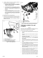
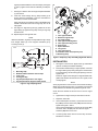
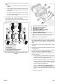
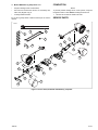
-J06145
REV. 2015-05-01
ROAD GLIDE LED BULLET FOG LAMP MOUNTING KITS
security system. Turn ignition switch OFF. IMMEDIATELY
remove the main fuse.
GENERAL
Kit Numbers
•
68000183, 68000184
Models
WITHOUT security siren: See the service manual.
Remove main fuse.
REMOVAL
For model fitment information, see the P&A retail catalog or
the Parts and Accessories section of www.harley-davidson.com
(English only).
Installation Requirements
Separate purchase of an LED Bullet Fog Lamp Kit (Part No.
68000090 or 68000092) is required for proper installation of
this kit. See the P&A retail catalog or the Parts and Accessories
section of www.harley-davidson.com (English only).
1.
Lay a clean pad or blanket on the work surface to protect
the painted surfaces of the outer fairing.
2.
Remove windshield. Remove outer fairing. See the service
manual.
3.
Disconnect the turn signal wiring from the mating connectors on the inner fairing. Record wire routing inside the
outer fairing. Peel back the adhesive-backed wire retention
pads to free the wiring.
Temporary use of two common 1/4-20 nuts (not provided) is
required for the fog lamp alignment procedure.
Loctite® 243 Medium Strength Threadlocker and Sealant - Blue
(Part No. 99642-97) is required for proper installation of this
kit.
Cut the turn signal wires about 5-6 in (125-152 mm) from
the inner fairing connector to enable turn signal removal
from stalk. Remove turn signal mount from inside the outer
fairing. Save turn signal, mount and connector for reuse.
4.
These items are available from a Harley-Davidson dealer.
The rider's safety depends upon the correct installation
of this kit. Use the appropriate service manual procedures.
If the procedure is not within your capabilities or you do
not have the correct tools, have a Harley-Davidson dealer
perform the installation. Improper installation of this kit
could result in death or serious injury. (00333a)
Place the outer fairing, bottom down, on the protected
work surface.
NOTE
The drill guides are side-specific. Guides fit into cavities in the
fairing at the turn signal mounting location.
5.
See Figure 7. Get the drill guides (9, 10) from the kit.
Temporarily position one drill guide into the correct turn
signal mounting cavities on one side of the fairing.
Note the areas where the drill guide is in contact with the
fairing paint.
NOTE
6.
This instruction sheet refers to service manual information. A
service manual for this year/model motorcycle is required for
this installation. One is available from a Harley-Davidson dealer.
Remove the drill guide. Lay strips of masking tape onto
the fairing surface to protect the finish where the drill guide
contacts the fairing.
7.
Position the drill guide back into the turn signal mounting
cavities. Secure with masking tape.
8.
Carefully insert a 1/4 in (6 mm) drill bit through the drill
guide. Drill a hole through the fairing.
Kit Contents
See Figure 7 and Table 1.
PREPARATION
Remove the drill. Remove the drill guide.
•
To prevent accidental vehicle start-up, which could cause
death or serious injury, remove main fuse before proceeding. (00251b)
NOTE
•
•
NOTES
READ ALL DIRECTIONS for enlarging the hole
BEFORE STARTING.
FAILURE TO FOLLOW THESE DIRECTIONS could
result in a visible gap between the turn signal stalk
and fairing.
WITH security siren: With security fob present, turn
ignition switch ON. See the service manual. Disarm
-J06145
Many Harley-Davidson® Parts & Accessories are made of plastics and metals which can be recycled.
Please dispose of materials responsibly.
1 of 6
9.
Carefully enlarge the hole per the following directions,
using a 5/8 in (16 mm) diameter drill bit:
a.
See Figure 1. When enlarging the hole, drill perpendicular to the fairing (1) surface (2) to avoid the bit
"walking" and marring the finish.
b.
Once through the hole, continue power to the drill.
Tip the drill into the fairing as though parallel to the
ground (3) in installed position to elongate the hole
vertically.
c.
DO NOT oversize the hole! Use a coarse round file
of 1/2 in (13 mm) diameter or less to remove excess
fairing material slowly. Test-fit the turn signal stalk
into the hole often to get a snug fit around the boss
on the stalk.
is08584
1
3
10. Repeat steps 5-9 on the opposite side.
11. See Figure 2. Remove and discard the bolt (3) and washer
from the engine guard support (2) on the inner fairing (1).
Support the rear part of the inner fairing if necessary.
Repeat on other side.
2
1. Inner fairing, FLTR
2. Engine guard support
3. Bolt
is08582
Figure 2. Remove Bolt From Engine Guard Support
TEMPORARY ASSEMBLY FOR LAMP
ALIGNMENT
3
NOTES
See Figure 3. Due to limited access to mounting screws, fog
lamps (1) MUST be aligned before final installation.
The fog lamps and gaskets are side-specific.
2
1
•
Fog lamps must be installed with the Bar & Shield logo at
the top.
•
Back side of gasket has an embossed letter "R" (right) or
"L" (left).
1.
See Figure 4. Get the correct-side turn signal standoff (1)
and gasket (4) from this kit.
Get the correct-side fog lamp (11) from the LED Bullet
Fog Lamp Kit.
1. Outer fairing, FLTR
2. Drill perpendicular to fairing surface
3. Drill as though parallel to ground
Figure 1. Drill Elongated Hole
-J06145
Get the original equipment (OE) turn signal lamp (2), screw
(5) and the correct-side turn signal mount (9) removed
earlier.
2.
Feed the turn signal wiring through the rear hole in the
standoff and the large hole in the gasket.
3.
Feed the fog lamp wiring through the large hole in the
gasket. Slide the gasket over the long boss of the standoff.
Capture the fog lamp wiring between the gasket and the
notch in the standoff.
4.
Feed the turn signal and fog lamp wiring through the
rectangular opening in the turn signal mount.
5.
Temporarily assemble the turn signal lamp (2), gasket (4),
standoff (1) and mount (9) with screw (5).Tighten securely.
6.
Get a fog lamp bracket (3), long screw (8) and a common
1/4-20 nut (10, not provided). Temporarily assemble the
bracket to the standoff with the screw and nut. Rotate the
2 of 6
fog lamp bracket toward the rear until it stops (see Figure
3, Item 2). Tighten screw and nut sufficiently to hold position.
is08599
7.
See Figure 4. Get the short screw (6) and split lockwasher
(7) from the kit.
8.
Insert the screw through the fog lamp bracket (3) as
shown. Place the lockwasher (7) into the counterbore in
the bracket, over the screw threads.
11
Apply a few drops of Loctite 243 - Blue to the clean screw
threads. Thread the screw into the fog lamp, but do not
fully tighten.
7
9.
8
1.
2.
3.
4.
5.
6.
7.
8.
9.
10.
11.
After final installation, fog lamps are adjustable through a range
from straight ahead (5) to two degrees downward (6) by
loosening screw (3).
is08591
1
6
4
1.
2.
3.
4.
5.
6.
2
Turn signal standoff
Bullet turn signal lamp
Fog lamp bracket
Turn signal standoff gasket
Turn signal mounting screw
Short screw
Split lockwasher
Long screw
Turn signal mount
Common 1/4-20 nut (temporary use)
Bullet fog lamp
Figure 4. Temporary Lamp Assembly (Right Side Shown)
INSTALLATION
1.
See Figure 4. Remove turn signal screw (5) and bracket
(9) from one lamp and standoff assembly.
2.
Place bracket inside fairing in original position. Feed the
turn signal and fog lamp wiring through the rearmost hole
in the outer fairing, and the rectangular opening in the turn
signal mount.
Bullet fog lamp
Rotate bracket toward rear until it stops
Long screw
Turn signal lamp
Fog lamp aimed parallel to turn signal
Fog lamp aimed two degrees below parallel
Figure 3. Fog Lamp Alignment
9
1
NOTE
2
5
4
10. Repeat steps for the opposite side.
5
10
3
See Figure 3. Align the fog lamp (1) parallel to the turn
signal lamp (4). Tighten the fog lamp screw per fog lamp
kit instructions.
3
6
Install turn signal screw through turn signal bracket boss,
gasket and standoff. Thread into the turn signal, but do
not fully tighten.
NOTE
Gently tug the wires to remove excess slack outside the fairing.
Make sure that the fog lamp wire is not pinched, and remains
routed between the standoff and gasket through the notch.
Route the wires behind the formed hook in the turn signal
mount.
3.
Tighten the turn signal screw per the service manual.
4.
Repeat on other side.
5.
Use a sealed splice connector (11) from the kit to secure
the (V/BN) connector wire to the (V/BN) wire from the turn
signal. See Figure 5, Item 6.
Use a second sealed splice connector to secure the (BE)
connector wire to the (BE) wire from the turn signal.
Leave the (BK) wires cut for now.
6.
-J06145
Cut the fog lamp wires close to the two-way connector.
Discard the connector.
3 of 6
7.
Measure about 8 in (200 mm) from the end of the fog lamp
wires.
a.
8.
is08590
2
Remove 1-2 in (25-50 mm) of the outer sleeve at that
location.
b.
Cut the (BK) wire inside the gap farthest from the fog
lamp. Pull the excess (BK) wire from the end of the
wire sleeve.
c.
See Figure 5. Use a sealed splice connector (6) from
the kit to secure the (BK) fog lamp wire to the (BK)
turn signal wires cut earlier.
1
3
4
5
See Figure 6. Insert a fog lamp jumper wire harness (6)
from the kit into cavity 4 of connector [31B].
7
Use a sealed splice connector to secure the (R) fog lamp
wire to the (BE/BK) jumper wire.
BK
is08583a
RE/O
BE/BK
BE
4
[31RA] 4 3 2 1
5
BK
5
BE/BK
V/BN
BK
1.
2.
3.
4.
5.
6.
7.
[31LA]
1 2 3 4 [31LB]
BE/BK
R
BE/BK
1 2 3 4
[31RB] 4 3 2 1
6
BK
BE/PK
BE
R
V/BN
BE
BE
BK
6
BK
Front turn signal connector 31B
Connector clip faces upward
Blue (BE) wire in cavity 1
Violet/brown (V/BN) wire in cavity 2
Black (BK) wire in cavity 3
Blue/black (BE/BK) jumper wire into cavity 4
Terminal clips face downward
Figure 6. Insert Jumper Terminal Into Cavity 4
9.
3
1
3
2
1.
2.
3.
4.
5.
6.
Right front turn signal
Left front turn signal
Fog lamp (2)
FLTR fairing harness
Fog lamp jumper wire harness (2)
Sealed splice connector (8)
Figure 5. Wiring Diagram, Road Glide LED Bullet Fog
Lamps
-J06145
Repeat steps 1-8 on the opposite side.
10. Secure the turn signal wiring and fog lamp wires under
the adhesive-backed wire retention pads peeled back
earlier. Replace any damaged pads (F, available separately).
11. Secure excess wire with tape or cable straps in original
locations.
12. Position outer fairing near the front of the vehicle. Connect
turn signal wiring.
13. Get the two long screws (8) from the kit. Apply a few drops
of Loctite 243 - Blue to the clean screw threads.
14. Install the outer fairing per the service manual, with the
following exception:
a.
Use long screws (8, installed earlier with temporary
nuts) from this kit to secure the fog lamp (Item B)
bracket (5) to the turn signal standoff (1, 2).
b.
Remove and discard temporary nuts. Hand thread
screw (8) into the inner fairing media box. NOTE: It
could take a few tries to get the media box threaded
insert to engage the screw threads.
c.
Once the screw threads are engaged, tighten to 7.5
ft-lbs (10.2 N-m). DO NOT OVER-TIGHTEN! Overtightening could damage threaded inserts in media
box.
d.
Repeat on other side.
4 of 6
15. Models WITHOUT fog lamp switch: See:
COMPLETION
•
the parts catalog for this model vehicle,
•
the Parts and Accessories section of www.harley-davidson.com (English only) or
To prevent possible damage to the sound system, verify that
the ignition switch is OFF before installing the main fuse.
•
a Harley-Davidson dealer
1.
NOTE
for an OE fog lamp switch. Install the switch per the service
manual.
See the service manual. Install main fuse.
SERVICE PARTS
is08558
12
E
13
11
7
D
3
10
6
F
8
A
2
E
5
6
7
4
1
3
8
A
9
Figure 7. Service Parts, Road Glide LED Auxiliary Lamp Kits
-J06145
5 of 6
SERVICE PARTS
Table 1. Service Parts
Kit
Kit 68000183
(Chrome)
Kit 68000184
(Black)
Parts common
to BOTH kits
Item
Description (Quantity)
Part Number
1
Standoff, turn signal (right, Chrome)
67800558
2
Standoff, turn signal (left, Chrome)
67800559
3
Bracket, fog lamp (Chrome) (2)
68000185
1
Standoff, turn signal (right, Black)
67800560
2
Standoff, turn signal (left, Black)
67800561
3
Bracket, fog lamp (Black) (2)
68000186
4
Gasket, right
68000187
5
Gasket, left
68000188
6
Screw, hex socket button head, 5/16-18 x 3/4 in (19 mm) (Chrome) (2)
Not sold separately
7
Lockwasher, split, 5/16 in, stainless steel (2)
Not sold separately
8
Cap screw, hex socket head, 1/4-20 x 3-1/4 in (83 mm) long, Grade 8 (2) 10500081
9
Drill guide (right)
Not sold separately
10
Drill guide (left)
Not sold separately
11
Sealed splice connector (8)
70585-93
12
Cable strap (2)
10065
13
Wire harness, fog lamp jumper (2)
69201503
Items mentioned in text, but not included in kit:
-J06145
A
Original equipment (OE) turn signal lamp (2)
B
OE turn signal mount (2)
C
OE turn signal screw (2)
D
1/4-20 nut (2, for temporary use)
E
LED Fog Lamp Kit (separate purchase)
F
Adhesive-backed wire retention pad (Part No. 11100066)
6 of 6