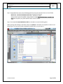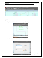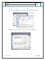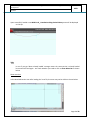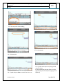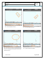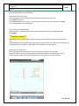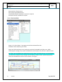
1
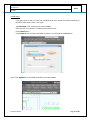
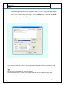
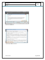
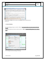
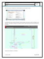
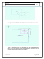
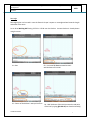
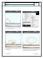
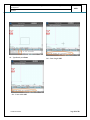
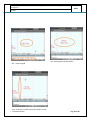
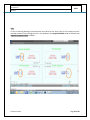
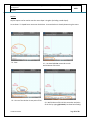
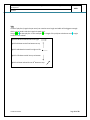
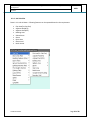
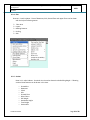
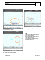
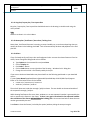
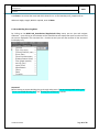
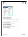
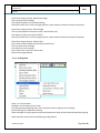
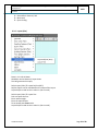
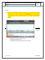
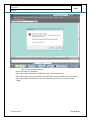
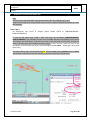
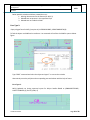
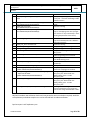
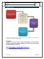
Online Building Plan Sanction User Manual - Building Plan – Fresh unauthorized regularized colony
Development
MCD
Architect
Below possible mistake could have created the error:
1. Missing relevant text for the feature (Ex: KD,2,3)
2. Related text not present in the respective layer
3. Related text not inside the PLINE
Error Type 2:
Open polygon found in MCD_Canopies At (112706.83204895,-35820.7800805769,0)
To find the object use PLINE and co-ordinate. List command will confirm the PLINE is open as below
figure.
Type ‘PEDIT’ command and select the object and type ‘C’ to correct the mistake.
Alternatively erase the polyline and corresponding text and redraw with the help of menu.
Error Type 3:
MCD_Cupboard not having expected syntax for Object handle 9B1AB at (60884.9875723905,11852.773984551,0) (Ex:CUP,1,PN,1.5)
Confidential to MCD
Page 62 of 68