1
SERVICE STATION MANUAL
898998
DORSODURO FACTORY ABS
SERVICE STATION
MANUAL
DORSODURO FACTORY ABS
THE VALUE OF SERVICE
As a result of continuous updates and specific technical training programmes for Aprilia products, only
Aprilia Official Network mechanics know this vehicle fully and have the specific tools necessary to carry
out maintenance and repair operations correctly.
The reliability of the vehicle also depends on its mechanical conditions. Checking the vehicle before riding
it, its regular maintenance and the use of original Aprilia spare parts only are essential factors!
For information on the nearest Official Dealer and/or Service Centre consult our website:
www.aprilia.com
Only by requesting aprilia original spare parts can you be sure of purchasing products that were
developed and tested during the actual vehicle design stage. All aprilia original spare parts undergo
quality control procedures to guarantee reliability and durability.
The descriptions and images in this publication are given for illustrative purposes only and are not binding.
While the basic characteristics as described and illustrated in this booklet remain unchanged, Piaggio &
C. S.p.A. reserves the right, at any time and without being required to update this publication beforehand,
to make any changes to components, parts or accessories, which it considers necessary to improve the
product or which are required for manufacturing or construction reasons.
Not all versions/models shown in this publication are available in all countries. The availability of individual
models should be confirmed with the official aprilia sales network.
The Aprilia trademark is the property of Piaggio & C. S.p.A.
© Copyright 2013 - Piaggio & C. S.p.A. All rights reserved. Reproduction of this publication in whole or
in part is prohibited.
Piaggio & C. S.p.A. Viale Rinaldo Piaggio, 25 - 56025 PONTEDERA (PI), Italy
www.piaggio.com
SERVICE STATION MANUAL
DORSODURO FACTORY ABS
This manual provides the main information to carry out regular maintenance operations on your vehicle.
This manual is intended to aprilia Dealers and their qualified mechanics; several concepts have been
deliberately omitted as they are considered unnecessary. As it is not possible to include complete
mechanical notions in this manual, users should have basic mechanical knowledge or minimum
knowledge about the procedures involved when repairing scooters. Without this knowledge, repairing or
checking the vehicle may be inefficient or even dangerous. As the vehicle repair and check procedures
are not described in detail, be extremely cautious so as not to damage components or injure individuals.
In order to optimise customer satisfaction when using our vehicles, Piaggio & C. S.p.a. commits itself
to continually improve its products and the relative documentation. The main technical modifications and
changes in repair procedures are communicated to all Aprilia Sales Outlets and its International
Subsidiaries. These changes will be introduced in the subsequent editions of the manual. In case of
need or further queries on repair and check procedures, consult Aprilia CUSTOMER DEPARTMENT,
which will be prepared to provide any information on the subject and any further communications on
updates and technical changes related to the vehicle.
NOTE Provides key information to make the procedure easier to understand and carry out.
CAUTION Refers to specific procedures to carry out for preventing damages to the vehicle.
WARNING Refers to specific procedures to carry out to prevent injuries to the repairer.
Personal safety Failure to completely observe these instructions will result in serious risk of personal
injury.
Safeguarding the environment Sections marked with this symbol indicate the correct use of the vehicle
to prevent damaging the environment.
Vehicle intactness The incomplete or non-observance of these regulations leads to the risk of serious
damage to the vehicle and sometimes even the invalidity of the guarantee
INDEX OF TOPICS
CHARACTERISTICS
CHAR
SPECIAL TOOLS
S-TOOLS
MAINTENANCE
MAIN
TROUBLESHOOTING
TROUBL
ELECTRICAL SYSTEM
ELE SYS
ENGINE FROM VEHICLE
ENG VE
ENGINE
POWER SUPPLY
ENG
P SUPP
SUSPENSIONS
SUSP
CHASSIS
CHAS
BRAKING SYSTEM
BRAK SYS
CLUTCH SYSTEM
CLU SYS
COOLING SYSTEM
COOL SYS
BODYWORK
BODYW
PRE-DELIVERY
PRE DE
INDEX OF TOPICS
CHARACTERISTICS
CHAR
Characteristics
DORSODURO FACTORY ABS
Rules
Safety rules
Carbon monoxide
If you need to keep the engine running while working on the vehicle, please ensure that you do so in
an open or very well ventilated area. Never run the engine in an enclosed area. If you do work in an
enclosed area, make sure to use a fume extraction system.
CAUTION
EXHAUST EMISSIONS CONTAIN CARBON MONOXIDE, A POISONOUS GAS WHICH CAN CAUSE
LOSS OF CONSCIOUSNESS AND EVEN DEATH.
Fuel
CAUTION
THE FUEL USED TO POWER INTERNAL COMBUSTION ENGINES IS HIGHLY FLAMMABLE AND
MAY BE EXPLOSIVE UNDER CERTAIN CONDITIONS. IT IS THEREFORE RECOMMENDED TO
CARRY OUT REFUELLING AND MAINTENANCE PROCEDURES IN A VENTILATED AREA WITH
THE ENGINE SWITCHED OFF. DO NOT SMOKE DURING REFUELLING AND NEAR FUEL VAPOURS, AVOIDING ANY CONTACT WITH NAKED FLAMES, SPARKS OR OTHER SOURCES
WHICH MAY CAUSE THEM TO IGNITE OR EXPLODE.
DO NOT DISPERSE FUEL IN THE ENVIRONMENT.
KEEP OUT OF THE REACH OF CHILDREN
Hot components
The engine and the exhaust system components become very hot and remain hot for some time after
the engine has been switched off. When handling these components, wear insulating gloves or wait
until the engine and the exhaust system have cooled down.
Coolant
The coolant contains ethylene glycol which, under certain conditions, can become flammable.
When it burns, ethylene glycol produces an invisible flame which however can cause burns.
CAUTION
TAKE CARE NOT TO POUR COOLANT ONTO HOT ENGINE OR EXHAUST SYSTEM COMPONENTS; THE FLUID MAY CATCH FIRE AND BURN WITH INVISIBLE FLAMES. WHEN CARRYING
OUT MAINTENANCE OPERATIONS, IT IS ADVISABLE TO WEAR LATEX GLOVES. EVEN
THOUGH IT IS TOXIC, COOLANT HAS A SWEET FLAVOUR WHICH MAKES IT VERY ATTRACTIVE TO ANIMALS. NEVER LEAVE THE COOLANT IN OPEN CONTAINERS IN AREAS ACCESSIBLE TO ANIMALS AS THEY MAY DRINK IT.
CHAR - 8
DORSODURO FACTORY ABS
Characteristics
KEEP OUT OF THE REACH OF CHILDREN
DO NOT REMOVE THE RADIATOR CAP WHEN THE ENGINE IS STILL HOT. THE COOLANT IS
UNDER PRESSURE AND MAY CAUSE BURNS.
Used engine oil and transmission oil
CAUTION
IT IS ADVISABLE TO WEAR PROTECTIVE IMPERMEABLE GLOVES WHEN SERVICING THE VEHICLE.
THE ENGINE OR GEARBOX OIL MAY CAUSE SERIOUS INJURIES TO THE SKIN IF HANDLED
FOR PROLONGED PERIODS OF TIME AND ON A REGULAR BASIS.
WASH YOUR HANDS CAREFULLY AFTER HANDLING OIL.
HAND THE OIL OVER TO OR HAVE IT COLLECTED BY THE NEAREST USED OIL RECYCLING
COMPANY OR THE SUPPLIER.
DO NOT DISPOSE OF OIL IN THE ENVIRONMENT
KEEP OUT OF THE REACH OF CHILDREN
Brake and clutch fluid
BRAKE AND CLUTCH FLUIDS CAN DAMAGE THE PLASTIC OR RUBBER PAINTED SURFACES.
WHEN SERVICING THE BRAKING SYSTEM OR THE CLUTCH SYSTEM, PROTECT THESE COMPONENTS WITH A CLEAN CLOTH. ALWAYS WEAR PROTECTIVE GOGGLES WHEN SERVICING
THESE SYSTEMS. BRAKE AND CLUTCH FLUIDS ARE EXTREMELY HARMFUL FOR YOUR
EYES. IN THE EVENT OF ACCIDENTAL CONTACT WITH THE EYES, RINSE THEM IMMEDIATELY
WITH ABUNDANT COLD, CLEAN WATER AND SEEK MEDICAL ADVICE.
KEEP OUT OF THE REACH OF CHILDREN
Battery electrolyte and hydrogen gas
CAUTION
THE BATTERY ELECTROLYTE IS TOXIC, CORROSIVE AND AS IT CONTAINS SULPHURIC ACID,
IT CAN CAUSE BURNS WHEN IN CONTACT WITH THE SKIN. WHEN HANDLING BATTERY
ELECTROLYTE, WEAR TIGHT-FITTING GLOVES AND PROTECTIVE APPAREL. IN THE EVENT
OF SKIN CONTACT WITH THE ELECTROLYTIC FLUID, RINSE WELL WITH PLENTY OF CLEAN
WATER. IT IS PARTICULARLY IMPORTANT TO PROTECT YOUR EYES BECAUSE EVEN TINY
AMOUNTS OF BATTERY ACID MAY CAUSE BLINDNESS. IF THE FLUID GETS IN CONTACT WITH
YOUR EYES, WASH WITH ABUNDANT WATER FOR FIFTEEN MINUTES AND CONSULT AN EYE
SPECIALIST IMMEDIATELY. THE BATTERY RELEASES EXPLOSIVE GASES; KEEP IT AWAY
FROM FLAMES, SPARKS, CIGARETTES OR ANY OTHER HEAT SOURCES. ENSURE ADEQUATE VENTILATION WHEN SERVICING OR RECHARGING THE BATTERY.
KEEP OUT OF THE REACH OF CHILDREN
BATTERY LIQUID IS CORROSIVE. DO NOT POUR IT OR SPILL IT, PARTICULARLY ON PLASTIC
COMPONENTS. ENSURE THAT THE ELECTROLYTIC ACID IS COMPATIBLE WITH THE BATTERY TO BE ACTIVATED.
Maintenance rules
GENERAL PRECAUTIONS AND INFORMATION
When repairing, dismantling and reassembling the vehicle, follow the recommendations given below
carefully.
CHAR - 9
Characteristics
DORSODURO FACTORY ABS
BEFORE DISASSEMBLING COMPONENTS
•
Before dismantling components, remove dirt, mud, dust and foreign bodies from the vehicle.
Use the special tools designed for this bike, as required.
COMPONENTS REMOVAL
•
Do not loosen and/or tighten screws and nuts using pliers or any other tools than the specific
wrench.
•
Mark positions on all connection joints (pipes, cables etc.) before separating them, and
identify them with distinctive symbols.
•
Each component needs to be clearly marked to enable identification during reassembly.
•
Clean and wash the dismantled components carefully using a low-flammability detergent.
•
Keep mated parts together since they have "adjusted" to each other due to normal wear.
•
Some components must be used together or replaced completely.
•
Keep away from heat sources.
REASSEMBLING COMPONENTS
CAUTION
BEARINGS MUST ROTATE FREELY, WITHOUT JAMMING AND/OR NOISE, OTHERWISE, THEY
NEED TO BE REPLACED.
•
Only use ORIGINAL Aprilia SPARE PARTS.
•
Comply with lubricant and consumables use guidelines.
•
Lubricate parts (whenever possible) before reassembling them.
•
When tightening nuts and screws, start either from the components with the largest diameter
or from the innermost components, proceeding diagonally. Tighten nuts and screws in successive steps before applying the tightening torque.
•
Always replace self-locking nuts, washers, sealing rings, circlips, O-rings (OR), cotter pins
and screws with new parts if the thread is damaged.
•
When assembling the bearings, make sure to lubricate them well.
•
Check that each component is assembled correctly.
•
After a repair or routine maintenance, carry out pre-ride checks and test the vehicle on
private grounds or in an area with low traffic.
•
Clean all mating surfaces, oil seal rims and gaskets before refitting. Smear a thin layer of
lithium-based grease on the oil seal rims. Reassemble oil seals and bearings with the brand
or batch number facing outward (visible side).
ELECTRICAL CONNECTORS
Electric connectors must be disconnected as described below; failure to comply with this procedure
causes irreparable damage to both the connector and the wiring harness:
Press the relative safety clips, if applicable.
•
CHAR - 10
Grip the two connectors and disconnect them by pulling them in opposite directions.
DORSODURO FACTORY ABS
•
Characteristics
If any signs of dirt, rust, moisture, etc. are noted, clean the inside of the connector carefully
with a jet of compressed air.
•
Ensure that the cables are correctly fastened to the internal connector terminals.
•
Then connect the two connectors, ensuring that they couple correctly (if fitted with clips, you
will hear them "click" into place).
CAUTION
DO NOT DISCONNECT CONNECTORS BY PULLING THE CABLES.
NOTE
THE TWO CONNECTORS CAN ONLY BE CONNECTED IN ONE DIRECTION: CONNECT THEM
THE RIGHT WAY ROUND.
TIGHTENING TORQUES
CAUTION
IN THE EVENT THAT A SELFBRAKING NUT IS UNSCREWED, IT IS NECESSARY TO REPLACE
IT WITH A NEW ONE.
CAUTION
REMEMBER THAT THE TIGHTENING TORQUES FOR ALL FASTENING ELEMENTS ON WHEELS,
BRAKES, WHEEL AXLES AND ANY OTHER SUSPENSION COMPONENTS PLAY A KEY ROLE
IN ENSURING VEHICLE SAFETY AND MUST COMPLY WITH SPECIFIED VALUES. CHECK THE
TIGHTENING TORQUES OF FASTENING ELEMENTS ON A REGULAR BASIS AND ALWAYS USE
A TORQUE WRENCH TO REASSEMBLE THESE COMPONENTS. FAILURE TO COMPLY WITH
THESE RECOMMENDATIONS MAY CAUSE ONE OF THESE COMPONENTS TO LOOSEN OR
EVEN DETACH, CAUSING A WHEEL TO LOCK OR COMPROMISING VEHICLE HANDLING. THIS
MAY LEAD TO FALLS, WITH THE RISK OF SERIOUS INJURY OR DEATH.
Running-in
Running the engine in correctly is essential for ensuring engine longevity and functionality. Twisty roads
and gradients are ideal for running in the engine, brakes and suspension effectively. Vary your riding
speed during the running in period. This ensures that components operate in "loaded" conditions and
then "unloaded" conditions, allowing the engine components to cool.
CAUTION
THE FULL PERFORMANCE OF THE VEHICLE IS ONLY AVAILABLE AFTER THE SERVICE AT
THE END OF THE RUNNING IN PERIOD.
Follow these guidelines:
•
Do not twist the throttle grip abruptly and completely when the engine is working at a low
revs, either during or after run-in.
•
During the first 100 Km (62 miles) use the brakes gently, avoiding sudden or prolonged
braking. That is to permit the adequate adjustment of the pad friction material to the brake
discs.
AFTER THE SPECIFIED MILEAGE, TAKE YOUR VEHICLE TO AN Official Aprilia Dealer FOR THE
CHECKS INDICATED IN THE "AFTER-RUN-IN" TABLE IN THE SCHEDULED MAINTENANCE
SECTION TO AVOID INJURING YOURSELF, OTHERS AND /OR DAMAGING THE VEHICLE.
CHAR - 11
DORSODURO FACTORY ABS
Characteristics
Vehicle identification
Write down the chassis and engine number in the specific space in this booklet. The chassis number
is handy when purchasing spare parts.
CAUTION
THE MODIFICATION OF THE IDENTIFICATION CODES IS A SERIOUS PUNISHABLE CRIME.
HOWEVER, THE LIMITED WARRANTY FOR NEW VEHICLES WILL BE VOID IF THE VEHICLE
IDENTIFICATION NUMBER (VIN) HAS BEEN MODIFIED OR NOT PROMPTLY DETERMINED.
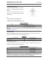
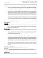
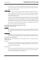
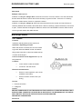
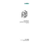
This number consists of numbers and letters, as in the example shown below.
ZD4SMB000YSXXXXXX
KEY:
ZD4: WMI (World manufacturer identifier) code;
SM: model;
B00: version variation;
0: free digit
Y year of manufacture
S: production plant (S= Scorzè);
XXXXXX: serial number (6 digits);
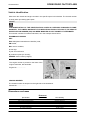
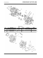
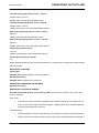
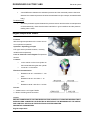
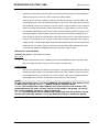
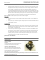
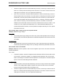
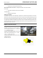
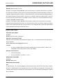
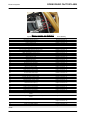
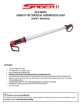
ENGINE NUMBER
The engine number is printed on the base of the
engine crankcase, left hand side.
Engine No. ....................
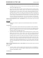
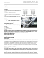
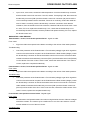
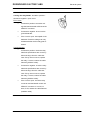
CHASSIS NUMBER
The chassis number is stamped on the right side of the headstock.
Chassis No. ....................
Dimensions and mass
DIMENSIONS
Specification
Max. length
Max. width (at hand guards)
Max. height
Saddle height
Wheelbase
Kerb weight
Dry weight (unfuelled)
CHAR - 12
Desc./Quantity
2210 mm (87.01 in)
905 mm (35.63 in)
1185 mm (46.65 in)
900 mm (35.43 in)
1505 mm (59.25 in)
206 kg (454 lb)
196 kg (432 lb)
DORSODURO FACTORY ABS
Characteristics
Engine
ENGINE
Specification
Model
Type
Desc./Quantity
M551M
90° longitudinal V-twin, 4-stroke, 4 valves per cylinder, 2 overhead camshafts.
2
749.9 cm³ (45.76 cu.in)
92 x 56.4 mm (3.62 x 2.22 cu.in)
0.11 - 0.18 mm (0.0043 - 0.0071 in)
0.16 - 0.23 mm (0.0063 - 0.0091 in)
11.0: 1
Electric starter
1400 ± 100 rpm
Multiple-disk, oil-bathed clutch with control on the left side of
the handlebar
Wet crankcase. Pressure system regulated by a trochoidal
pump
With dry cartridge filter
Fluid
No. of cylinders
Total engine capacity
Bore / stroke
Intake valve clearance
Exhaust valve clearance
Compression ratio
Electric
Engine idle speed
Clutch
Lubrication system
Air filter
Cooling
GEARBOX
Specification
Type
Desc./Quantity
Mechanical, 6 speeds with foot lever on the left hand side of
the engine
Transmission
GEAR RATIOS
Specification
Gear ratio
1st gear ratio
2nd gear ratio
3rd gear ratio
4th gear ratio
5th gear ratio
6th gear ratio
Final drive gear ratio
Desc./Quantity
Gear primary drive 38/71
14/36 (secondary)
17/32 (secondary)
20/30 (secondary)
22/28 (secondary)
23/26 (secondary)
24/25 (secondary)
16/46
Capacities
CAPACITY
Specification
Fuel capacity (reserve included)
Fuel reserve
Engine oil
Fork oil (check also the correct air level in the stem)
Coolant
Seats
Maximum weight limit
Desc./Quantity
12 l (2.64 UKgal; 3.17 US gal)
2.8 l (0.62 UKgal; 0.74 US gal)
3.0 l (without oil filter change) (0.66 UKgal; 0.79 USgal)
3.2 l (with oil filter change) (0.70 UKgal; 0.85 USgal)
441 cm³ (26.91 cu.in) (for each stanchion)
1.8 l (0.40 UKgal; 0.48 USgal)
2
400 kg (882 lb)
CHAR - 13
DORSODURO FACTORY ABS
Characteristics
Drive chain
DRIVE CHAIN
Specification
Type
Model
Desc./Quantity
Endless (without master link) and with sealed links. No. of links
108
525 ZRPK
Electrical system
ELECTRICAL SYSTEM
Specification
Battery
Main fuses
Secondary fuses
Alternator (permanent magnet type)
Desc./Quantity
12 V - 10 Ah YTX 12 - BS
30A
3A, 10A, 15A, 20A
13.5 V - 450 W at 6000 rpm
SPARK PLUGS
Specification
Standard spark plugs
Spark plug electrode gap
Resistance
Desc./Quantity
NGK CR7EKB
0.6 - 0.7 mm (0.024 - 0.028 in)
5 kOhm
BULBS
Specification
High beam light
Low beam light
Front daylight running light
Turn indicator light
Rear daylight running light / stop light
License plate light
Rpm indicator lighting
Multifunction display lighting
Desc./Quantity
12 V - 60 W H4
12 V - 50 W H4
12V - 6W H6
12V - 10W
LED
12V - 5W
LED
LED
WARNING LIGHTS
Specification
High beam light
Right turn indicator
Left turn indicator
General warning
Gear in neutral
Side stand down
Fuel reserve
ABS
Desc./Quantity
LED
LED
LED
LED
LED
LED
LED
LED
Frame and suspensions
CHASSIS
Specification
Type
Steering inclination angle
Trail
CHAR - 14
Desc./Quantity
Component chassis (bolted). Die-cast aluminium plates and
high-strength steel tubular chassis.
25.8°
108 mm (4.25 in)
DORSODURO FACTORY ABS
Characteristics
SUSPENSION
Specification
Front
Travel
Rear
Wheel travel
Desc./Quantity
Sachs upside-down stanchions with adjustable hydraulic
damping and 43mm (1.69 in) diameter stanchions
160 mm (6.3 in)
Oscillating swingarm with Sachs piggy-back single shock absorber and adjustable spring preloading, wheelbase and hydraulic compression and rebound damping.
155 mm (6.1 in)
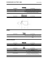
SIZES A AND B
Specification
Size A
Size B
Desc./Quantity
693.1 mm (27.29 in)
369.8 mm (14.56 in)
Brakes
BRAKES
Specification
Front
Rear
Desc./Quantity
Double floating disc, Ø 320 mm (12.60 in), radially-mounted
calliper with four Ø 32 mm (1.26 in) pistons and two calliper
pads
240 mm (9.45 in) disc brake with 34 mm (1.34 in) single piston
calliper
Wheels and tyres
WHEEL RIMS
Specification
Type
Front
Rear
Desc./Quantity
Light alloy rims with extractable bolt
3.50 x 17"
6.00 x 17"
TYRES
Specification
Tyre type (standard)
Front tyre
Front tyre pressure
Rear tyre
Rear tyre pressure
Desc./Quantity
PIRELLI CORSA III
DUNLOP SPORTMAX QUALIFIER
120/70 ZR17"
rider only: 2.3 bar (230 kPa) (33.36 PSI)
rider + passenger: 2.4 bar (240 kPa) (34.81 PSI)
180/55 ZR17"
rider only: 2.5 bar (250 kPa) (36.26 PSI)
rider + passenger: 2.7 bar (270 kPa) (39.16 PSI)
CHAR - 15
DORSODURO FACTORY ABS
Characteristics
Supply
FUEL SYSTEM
Specification
Type
Throttle valve diameter
Fuel
Desc./Quantity
Electronic injection (Multipoint)
Ø 52 mm (2.05 in)
Premium unleaded petrol, minimum octane rating 95 (NORM)
and 85 (NOMM)
Tightening Torques
Chassis
Front side
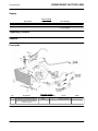
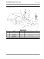
COOLING SYSTEM
pos.
1
2
Description
Fan fastener screw
Flanged TE screw fixing LH side radiator to trellis frame and radiator
bracket to engine
CHAR - 16
Type
M6x25
Quantity
3
2
Torque
3 Nm (2.21 lbf ft)
10 Nm (7.37 lbf ft)
Notes
-
DORSODURO FACTORY ABS
Characteristics
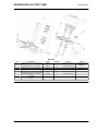
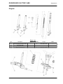
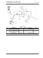
FRONT FORK - SHOWA
pos.
Description
Screws (fasten onto fork hubs)
pos.
Description
Screws (fasten onto fork hubs)
Bottom screw
Cap
1
Type
M8x40
Quantity
4
Torque
25 Nm (18.44 lb ft)
Notes
-
Torque
25 Nm (18.44 lb ft)
30 Nm (22.13 lb ft)
20 Nm (14.75 lb ft)
Notes
Loctite 242
-
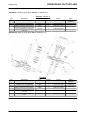
FRONT FORK - SACHS
1
2
3
Type
M8x40
-
Quantity
4
2
2
CHAR - 17
DORSODURO FACTORY ABS
Characteristics
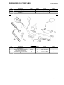
pos.
Description
Nut on pumping member pin
4
Type
Quantity
2
Torque
20 Nm (14.75 lb ft)
Notes
-
OPTION 01- Steering upper plate without a headstock cut.
STEERING - OPTION 1
pos.
1
1
2
3
4
Description
Headstock ring nut - pre-tightening
Type
M25x1
Quantity
1
Torque
30 Nm (22.13 lb ft)
Headstock ring nut - tightening
Headstock cap
Stainless steel TCC screw fastening
stanchions to upper and lower yokes
TCEI screw fastening U-bolt onto
fork yoke
M25x1
M22x1
M8x30
1
1
6
12 Nm (8.85 lb ft)
100 Nm (73.75 lb ft)
25 Nm (18.44 lb ft)
Notes
Steering package
settlement
-
M10x60
2
50 Nm (36.88 lb ft)
-
OPTION 02- Steering upper plate with a headstock cut.
CHAR - 18
DORSODURO FACTORY ABS
Characteristics
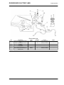
STEERING
pos.
1
1
2
2
3
4
5
Description
Headstock ring nut - pre-tightening
Type
M25x1
Quantity
1
Torque
30 Nm (22.13 lb ft)
Headstock ring nut - tightening
Headstock nut - pre-tightening
Headstock nut
Stainless steel TCC screw fastening
stanchions to upper and lower yokes
TCEI screw fastening U-bolt onto
fork yoke
Steering upper plate clamp closing
screw
M25x1
M22x1
M22x1
M8x30
1
1
1
6
12 Nm (8.85 lb ft)
10 Nm (7.37 lb ft)
25 Nm (18.44 lb ft)
25 Nm (18.44 lb ft)
Notes
Steering package
settlement
Loctite 243
Loctite 243
-
M10x60
2
50 Nm (36.88 lb ft)
-
M8x30
1
25 Nm (18.44 lb ft)
Loctite 243
CHAR - 19
DORSODURO FACTORY ABS
Characteristics
INSTRUMENT PANEL
pos.
1
Description
TCEI screw fastening instrument
panel mounting to fork yoke
Type
M6x20
Quantity
2
Torque
10 Nm (7.37 lbf ft)
Notes
-
Torque
6 Nm (4.42 lbf ft)
Notes
Loct. 243
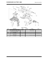
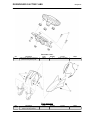
FRONT MUDGUARD
pos.
1
Description
TBEI screw fastening fork guard to
calliper mounting bracket
CHAR - 20
Type
M5x9
Quantity
6
DORSODURO FACTORY ABS
pos.
2
3
Characteristics
Description
TBEI screw fastening mudguard to
stanchions
Screw fastening number panel to
headlamp
Type
M5x9
Quantity
4
Torque
4 Nm (2.95 lbf ft)
Notes
-
-
4
1 Nm (0.74 lbf ft)
-
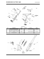
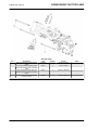
Description
TCEI screw fastening counterweight
to handlebar end
Stainless steel TCC screw fastening
upper U-bolt to lower clamp
Screws fastening light switch assembly
Type
M6x50
Quantity
2
Torque
10 Nm (7.37 lbf ft)
Notes
-
M8x25
4
25 Nm (18.44 lbf ft)
-
M4
2
1.5 Nm (1.11 lbf ft)
-
HANDLEBAR
pos.
1
2
3
CHAR - 21
DORSODURO FACTORY ABS
Characteristics
CLUTCH PUMP
pos.
1
2
3
4
5
6
Description
Clutch cylinder fastener
Union with breather and fixing pipe
Fastener for clutch pump on handlebar
Screw fastening clutch control
mounting on flywheel side crankcase
half
TBEI tank fixing screw
TBEI plate fixing screw
CHAR - 22
Type
M6
M10x1
-
Quantity
2
1+1
2
Torque
10 Nm (7.37 lbf ft)
25 Nm (18.44 lbf ft)
10 Nm (7.37 lbf ft)
Notes
-
M6
1
10 Nm (7.37 lbf ft)
-
M5x10
M6x12
1
1
6 Nm (4.42 lbf ft)
10 Nm (7.37 lbf ft)
-
DORSODURO FACTORY ABS
Characteristics
FRONT BRAKE PUMP
pos.
1
2
3
4
5
Description
Pipe union fastening brake pipe to
pump
Fastener for front brake pump on
handlebar
TBEI screw fastening the brake tank
to the plate
Plate fixing screw
Screw fastening the brake pipe to
steering base
Type
M10x1
Quantity
1
Torque
25 Nm (18.44 lbf ft)
Notes
-
-
2
10 Nm (7.37 lbf ft)
-
M6x20
1
10 Nm (7.37 lbf ft)
-
M6x12
M6x25
1
1
10 Nm (7.37 lbf ft)
10 Nm (7.37 lbf ft)
-
CHAR - 23
DORSODURO FACTORY ABS
Characteristics
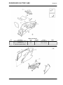
HEADLAMP
pos.
1
2
3
Description
TE screw fastening headlamp to
headlamp mounting and mudguard
to steering base
Fastener for front turn indicators
TCEI screw fastening headlamp
mounting to fork yoke
CHAR - 24
Type
M6x16
Quantity
2
Torque
10 Nm (7.37 lbf ft)
Notes
-
M5
M6
2
3
3 Nm (2.21 lbf ft)
10 Nm (7.37 lbf ft)
-
DORSODURO FACTORY ABS
Characteristics
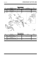
FRONT BODYWORK
pos.
1
2
3
-
Description
TBEI screw fastening front side panels to tank
TBEI screw fastening front side panels and duct to radiator
TBEI screw fastening ignition block
cover to spacer
Front tank fastener spacer
Type
M5x9
Quantity
6
Torque
4 Nm (2.95 lbf ft)
Notes
-
M6x16
4
6 Nm (4.42 lbf ft)
-
M5x9
3
4 Nm (2.95 lbf ft)
-
M6
2
10 Nm (7.37 lbf ft)
-
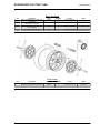
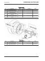
Quantity
1
12
Torque
80 Nm (59 lbf ft)
30 Nm (22.13 lbf ft)
Notes
Loctite 243
FRONT WHEEL
pos.
1
2
Description
Wheel axle nut
TE flanged screw fastening front disc
Type
M8x20
CHAR - 25
DORSODURO FACTORY ABS
Characteristics
FRONT BRAKE
pos.
1
2
-
Description
Union with breather (fixing pipe to
callipers)
TEFL screw (Fixing calliper to fork
stems)
Fastener for brake pipe on steering
base
CHAR - 26
Type
M10x1
Quantity
2
Torque
25 Nm (18.44 lbf ft)
Notes
-
M10x1.25
4
50 Nm (36.88 lbf ft)
-
M6x25
1
10 Nm (7.37 lbf ft)
-
DORSODURO FACTORY ABS
Characteristics
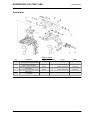
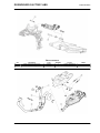
Central part
FRONT CHASSIS
pos.
1
2
3
4
5
Description
TCEI screw fastening shock absorber counterplate to RH frame bracket
TC TORX screw fastening trellis
frame to frame side panels
Screw fastening chain roller bracket
to LH plate
Screw fastening chain roller to chain
roller bracket
Screw fastening chain roller bracket
to LH plate
Type
M10x30
Quantity
1
Torque
50 Nm (36.88 lbf ft)
Notes
-
M12x53
4
80 Nm (59 lbf ft)
-
M8x35
1
25 Nm (18.44 lbf ft)
Loctite 243
M8x45
1
25 Nm (18.44 lbf ft)
Loctite 243
M8x20
1
25 Nm (18.44 lbf ft)
Loctite 243
CHAR - 27
DORSODURO FACTORY ABS
Characteristics
CENTRE FRAME
pos.
1
2
3
4
Description
TCEI screws fastening side panels to
engine
TCEI screw fastening lambda probe
plate to RH frame (pre-fit on RH side
panel
SWP self-tapping screw fastening
demand sensor mounting to demand
sensor
Flanged TE screw fastening demand
sensor to frame
CHAR - 28
Type
M12x282
Quantity
3
Torque
80 Nm (59 lbf ft)
Notes
-
M4x10
2
3 Nm (2.3 lbf ft)
-
M5x14
4
2.6 Nm (1.92 lbf ft)
-
M6x20
3
10 Nm (7.37 lbf ft)
-
DORSODURO FACTORY ABS
Characteristics
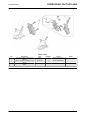
FOOTPEGS
pos.
1
2
3
Description
Upper screw fastening passenger
footrests to frame side panels
Lower TCEI screw fastening passenger footrests to rider footrest mounting
TCEI screw fastening rider footrest
mounting to frame
Type
M8x35
Quantity
2
Torque
25 Nm (18.44 lbf ft)
Notes
Loct. 243
M8x35
2
25 Nm (18.44 lbf ft)
Loct. 243
M8x35
4
28 Nm (20.65 lbf ft)
Loctite 243
CHAR - 29
DORSODURO FACTORY ABS
Characteristics
STAND ASSEMBLY
pos.
1
2
3
4
Description
Stand screw
Thin nut
Spring fixing pin
TCEI screw fastening stand switch
Type
M10x1.25
M10x1.25
M5x16
Quantity
1
1
1
2
Torque
10 Nm (7.37 lbf ft)
30 Nm (22.13 lbf ft)
7.5 Nm (5.53 lbf ft)
7 Nm (5.16 lbf ft)
Notes
Loctite 243
Loctite 243
-
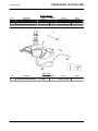
Torque
3 Nm (2.21 lbf ft)
10 Nm (7.37 lbf ft)
Notes
-
FUEL TANK
pos.
1
2
Description
TCEI screw fastening filler cap flange
Rear TE screw fastening tank
CHAR - 30
Type
M5x16
M6x90
Quantity
5
1
DORSODURO FACTORY ABS
Characteristics
FUEL PUMP
pos.
Description
TEFL screw fastening fuel pump
pos.
Description
Cross head self-tapping screw fastening separator / filter box
1
Type
M5x16
Quantity
6
Torque
6 Nm (4.42 lbf ft)
Notes
-
Torque
3 Nm (2.21 lbf ft)
Notes
-
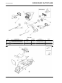
AIR FILTER BOX
1
Type
M5x20
Quantity
10
CHAR - 31
DORSODURO FACTORY ABS
Characteristics
pos.
2
3
4
-
Description
SWP self-tapping screw
Cross head self-tapping screw fastening cover / filter box
Cross head self-tapping screw fastening lateral cap / filter box
Cross head self-tapping screw
Type
M2.9x12 TCCR
M5x20
Quantity
2
8
Torque
3 Nm (2.21 lbf ft)
3 Nm (2.21 lbf ft)
Notes
-
M5x20
3
3 Nm (2.21 lbf ft)
-
M5x10
2
3 Nm (2.21 lbf ft)
-
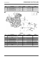
Description
Flanged TE screw fastening pinion
TCEI screw fastening Pin to gearbox
lever and Gearbox Lever to knurled
shaft
LH lock nut for ball joint
RH lock nut for ball joint
Screw fastening engine bracket /
clutch side crankcase half
Map sensor union (brass)
Map sensor union (steel)
LH ball joint on gearbox control lever
RH ball joint on gearbox control lever
Fastener for positive cable on engine
TE screw fastening negative cable to
engine
Type
M10x1.25x25
M6x16
Quantity
1
2
Torque
50 Nm (36.88 lbf ft)
10 Nm (7.37 lbf ft)
Notes
Loctite 270
-
M6
M6
M6
1
1
2
10 Nm (7.37 lbf ft)
10 Nm (7.37 lbf ft)
12 Nm (8.85 lbf ft)
-
M6x12
2
2
1
1
1
1
2 Nm (1.48 lbf ft)
3.50 Nm (2.58 lbf ft)
10 Nm (7.37 lbf ft)
10 Nm (7.37 lbf ft)
10 Nm (7.37 lbf ft)
10 Nm (7.37 lbf ft)
Loctite 243
Loctite 243
Loctite 243
Loctite 243
-
ENGINE
pos.
1
2
3
4
5
6
6
7
8
-
CHAR - 32
DORSODURO FACTORY ABS
Characteristics
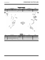
ELECTRICAL SYSTEM 1
pos.
1
2
Description
Coil fixing screw
TE screw fastening regulator to
frame
Type
M6
M6x30
Quantity
2
2
Torque
13 Nm (9.59 lbf ft)
10 Nm (7.37 lbf ft)
Notes
-
CHAR - 33
DORSODURO FACTORY ABS
Characteristics
ELECTRICAL SYSTEM 2
pos.
1
-
Description
Screw fastening ECU to filter box
base
Starter relay fastener
Type
-
Quantity
4
Torque
2.5 Nm (1.47 lbf ft)
Notes
-
-
2
3 - 4.2 Nm (2.21 - 3.1 lbf
ft)
-
Description
TCEI screw
Switch fastener
Type
M8x40
shear head
screw
M6x25
Quantity
1
1
Torque
25 Nm (18.44 lbf ft)
Manual
Notes
-
2
10 Nm (7.37 lbf ft)
-
LOCKS
pos.
1
2
3
TE screw fastening saddle lock / battery compartment to saddle mounting
CHAR - 34
DORSODURO FACTORY ABS
Characteristics
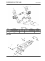
THROTTLE BODY
pos.
1
2
3
4
Description
Intake union fastener screw
RBW control unit fastener screw
Injector fastener screw
Injection Throttle Body fastener
screw
Type
M6
M5
M6
M6
Quantity
8
2
2
8
Torque
12 Nm (8.85 lb ft)
3.50 Nm (2.58 lbf ft)
12 Nm (8.85 lb ft)
12 Nm (8.85 lb ft)
Notes
Loctite 242
Loctite 242
Loctite 242
Loctite 242
Back side
CHAR - 35
DORSODURO FACTORY ABS
Characteristics
SADDLE MOUNTING
pos.
1
2
3
-
Description
Upper LH TCEI screw fastening saddle mounting to frame
Upper RH TCEI screw fastening saddle mounting to frame
Lower TCEI screw fastening Saddle
mounting to frame
TCEI screw fastening passenger
grab handles to frame
Type
M8x55
Quantity
1
Torque
25 Nm (18.44 lbf ft)
Notes
-
M8x60
1
25 Nm (18.44 lbf ft)
-
M8x40
2
25 Nm (18.44 lbf ft)
-
M8x80
4
30 Nm (22.13 lbf ft)
-
Description
Swingarm Pin adjustment bushing
Swingarm pin ring nut
Swingarm pin nut
TPSI screw fastening rear stand
bushing
TBEI screw fastening chain guard to
swingarm
TBEI screw fastening rear mudguard
to swingarm
TBEI screw fastening chain guard to
rear mudguard
TBEI screw fastening chain guide to
swingarm
Wheel axle nut
Flanged TBEI screw fastening chain
casing
Type
M6x40
Quantity
1
1
1
2
Torque
12 Nm (8.85 lb ft)
60 Nm (44.25 lb ft)
90 Nm (66.38 lb ft)
10 Nm (7.37 lb ft)
Notes
-
M5x9
1
6 Nm (4.42 lbf ft)
-
M5x9
2
6 Nm (4.42 lbf ft)
Loctite 243
M5x9
1
4 Nm (2.95 lbf ft)
-
M5x9
2
6 Nm (4.42 lbf ft)
-
M25x1.5
M5x9
1
2
120 Nm (88.5 lbf ft)
4 Nm (2.95 lbf ft)
Loctite 243
SWINGARM
pos.
1
2
3
4
5
6
7
8
9
10
CHAR - 36
DORSODURO FACTORY ABS
Characteristics
REAR SUSPENSION
pos.
1
2
Description
Upper TCEI mounting screw
Lower TCEI mounting screw
Type
M10x50
M10x90
Quantity
1
1
Torque
50 Nm (36.88 lbf ft)
50 Nm (36.88 lbf ft)
Notes
-
CHAR - 37
DORSODURO FACTORY ABS
Characteristics
EXHAUST SYSTEM
pos.
1
2
3
4
5
Description
SERPRESS self-locking nut fastening flange on head
Primary Clamp (between front/rear
manifolds and central manifold)
Silencer Clamp (between central
manifold and silencer)
Self-tapping TE screw fastening silencer mounting bracket to saddle
mounting
Self-tapping TE screw fastening front
silencer fixture to silencer mounting
bracket
Type
M8
Quantity
4
Torque
25 Nm (18.44 lbf ft)
Notes
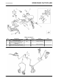
-
M6
2
7 Nm (5.16 lbf ft)
-
M6
1
7 Nm (5.16 lbf ft)
-
M8x20
2
25 Nm (18.44 lbf ft)
-
M8x35
2
35 Nm (25.81 lbf ft)
-
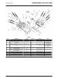
Type
M10
Quantity
5
Torque
50 Nm (36.88 lb ft)
Notes
-
M10x30
5
50 Nm (36.88 lb ft)
Loctite 270
REAR WHEEL
pos.
1
2
Description
Lower self-locking nut fastening
sprocket to sprocket carrier
TCEI screw fastening flexible coupling mounting on wheel
CHAR - 38
DORSODURO FACTORY ABS
Characteristics
REAR BRAKE
pos.
1
2
3
4
5
6
1
-
Description
Rear brake lever pin
Flanged TE screw fastening pump to
footrest mounting
TBEI screw fastening oil pipe to
swingarm and rubber pipe to footrest
mounting
Flanged self-locking nut
Screw + nut fastening pedal to brake
lever
Brake pipe union
Flanged TE screw fastening rear disc
Flanged TE screw
Type
M6
M6x20
Quantity
1
2
Torque
25 Nm (18.44 lbf ft)
10 Nm (7.37 lbf ft)
Notes
-
M5x12
4
6 Nm (4.42 lbf ft)
-
M6
M6
1
1+1
10 Nm (7.37 lbf ft)
10 Nm (7.37 lbf ft)
-
M10x1
M8x20
M6x16
2
5
1
25 Nm (18.44 lbf ft)
30 Nm (22.13 lbf ft)
10 Nm (7.37 lbf ft)
Loctite 243
-
CHAR - 39
DORSODURO FACTORY ABS
Characteristics
TAILLIGHT
pos.
1
2
3
4
CHAR - 40
Description
TE screw fastening tail light to license plate mounting frame
Fastener for rear turn indicators
Reflector fastener
Fastener for license plate light
Type
M6x45
Quantity
3
Torque
10 Nm (7.37 lbf ft)
Notes
-
M6
M5
M5
2
2
1
3 Nm (2.21 lbf ft)
2 Nm (1.47 lbf ft)
5 Nm (3.69 lbf ft)
-
DORSODURO FACTORY ABS
Characteristics
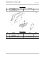
REAR BODYWORK 1
pos.
1
2
Description
Screws fastening battery cover to
compartment
TBEI screw fastening battery compartment to saddle mounting
Type
M5
Quantity
2+1
Torque
4 Nm (2.95 lbf ft)
Notes
-
M5x9
2
6 Nm (4.42 lbf ft)
-
REAR BODYWORK 2
pos.
1
2
3
Description
TBEI screw fastening LH - RH covers
to silencer
TBEI screw fastening tail fairing to
saddle mounting
Screw fastening tail fairing to battery
compartment
Type
M6x20
Quantity
4
Torque
10 Nm (7.37 lbf ft)
Notes
-
M5x9
2
6 Nm (4.42 lbf ft)
-
-
3
4 Nm (2.95 lbf ft)
-
CHAR - 41
DORSODURO FACTORY ABS
Characteristics
REAR BODYWORK 3
pos.
1
2
3
Description
TBEI screw fastening license plate
mounting to mounting
Fastener for license plate mounting
frame assembly to gusset plate saddle lock
Screw fastening license plate mounting cover to license plate mounting
CHAR - 42
Type
M5x9
Quantity
3
Torque
6 Nm (4.42 lbf ft)
Notes
-
M6
4
10 Nm (7.37 lbf ft)
-
-
3
0.8 Nm (0.59 lbf ft)
-
DORSODURO FACTORY ABS
Characteristics
ABS SYSTEM
pos.
-
Description
ABS ECU fastener screw
ABS ECU fastener nut
Type
M6x25
M6
Description
Special screw for fastening head
cover
Type
M6
Quantity
1
2
Torque
10 Nm (7.37 lbf ft)
10 Nm (7.37 lbf ft)
Notes
Loctite 243
-
Torque
9 Nm (6.64 lbf ft)
Notes
-
Engine
HEAD COVER
pos.
1
Quantity
8
CHAR - 43
DORSODURO FACTORY ABS
Characteristics
HEAD
pos.
Description
Water Temperature Sensor
Threaded plug for water sensor seat
Head stud bolt fastener nut - pretightening
Type
M12x1.5
M12x1.5
M10x1.25
Quantity
1
1
8
3
Head stud bolt fastener nut - tightening
M10x1.25
8
4
Fastener for Head / Cylinder / Outer
side crankcase
Fastener for Head / Cylinder / Inner
side crankcase
Nut fastening Stud Bolts / Head
Nut fastening Stud Bolts / Head
Bleed union fastener screw
Water bleed union (steel)
Water bleed union (brass)
M6
2
M6
4
12 Nm (8.85 lbf ft)
-
M6
M8
M5
-
4
2
4
1
2
12 Nm (8.85 lbf ft)
26 Nm (19.18 lbf ft)
6.5 Nm (4.79 lbf ft)
3.50 Nm (2.58 lbf ft)
2 Nm (1.48 lbf ft)
Loctite 243
Loctite 243
1
2
3
5
6
7
8
9
10
CHAR - 44
Torque
23 Nm (16.96 lbf ft)
10 Nm (7.38 lbf ft)
10 Nm (7.38 lbf ft)
Notes
Loctite Drise AL 506
Lubricate the
threads before tightening
13 Nm (9.59 lbf ft) + 90°
Lubricate the
+ 90°
threads before tightening
13 Nm (9.59 lbf ft)
-
DORSODURO FACTORY ABS
Characteristics
CYLINDER
pos.
1
2
Description
Chain tensioner fastener screw
Cylinder plate fastener screw
Type
M6
M6
Quantity
4
4
3
Chain tensioner adjustment screw
M6
2
Torque
13 Nm (9.59 lb ft)
7.84-9.81 Nm
(5.78-7.23 lb ft)
5.50 Nm (4.06 lb ft)
Notes
-
CHAR - 45
DORSODURO FACTORY ABS
Characteristics
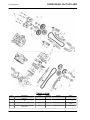
TIMING SYSTEM
pos.
1
1
2
3
Description
Camshaft gear fastener nut - pretightening
Camshaft gear fastener nut - tightening
Timing drive gear fastener screw
Special screw for fastening mobile /
fixed shoes
CHAR - 46
Type
M15x1
Quantity
4
Torque
30 Nm (22.13 lbf ft)
Notes
-
M15x1
4
90 Nm (66.38 lbf ft)
-
M24x1.5
2
40 Nm (29.50 lbf ft)
M8
4
19 Nm (14.01 lbf ft)
3M SCOTCH GRIP
2353
Loctite 242
DORSODURO FACTORY ABS
pos.
4
4
4
5
Description
Cam tower / head fastener screws pre-tightening
Cam tower / head fastener screws tightening
Viti fissaggio castelletto / testa - serraggio
Camshaft retainer plate fastener
screw
Characteristics
Type
M6
Quantity
16
M6
16
Torx
16
torx M3
8
Torque
4.90 - 6.86 Nm (3.61 5.06) lbf ft
9.81 - 12.75 Nm (7.24 9.40 lbf ft)
12 - 14 Nm (8.85 - 10.32
lbf ft)
3 Nm (2.21 lbf ft)
Notes
Loctite 270
CRANKSHAFT
pos.
1
2
Description
Crankshaft primary gear fastener nut
Connecting rod screw
Type
M24x1.5
M10
Quantity
1
4
Torque
Notes
270 Nm (199.14 lbf ft)
Anticlockwise nut
15 + 30 Nm (11.06 +
Lubricate the
22.13 lbf ft) + 50° ± 2°, threads before tightfinal control torque 65 ening
78 Nm (47.94 - 57.53 lbf
ft)
CHAR - 47
DORSODURO FACTORY ABS
Characteristics
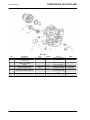
OIL PUMP
pos.
4
5
6
7
8
Description
Oil drainage plug
Fastening oil sensor on clutch side
crankcase half
Fastening oil filter union on clutch
side crankcase half
Oil filter
Oil pressure regulator valve
Oil pump fastener screw
Rose pipe fastener screw
Complete oil pump gear fastener
9
Oil pump cover fastener screw
1
2
3
CHAR - 48
Type
M16x1.5
-
Quantity
1
1
Torque
19 Nm (14.01 lbf ft)
13 Nm (9.59 lbf ft)
Notes
-
-
1
20 Nm (14.75 lbf ft)
-
3/4" Unf 16
M6
-
1
1
2
2
1
Loctite 242
-
M3
2
14 Nm (10.33 lbf ft)
43 Nm (31.72 lbf ft)
5.50 Nm (4.06 lbf ft)
12 Nm (8.85 lbf ft)
9-11 Nm (6.64-8.11 lbf
ft)
0.80 Nm (0.59 lbf ft)
-
DORSODURO FACTORY ABS
Characteristics
GEAR SELECTOR
pos.
1
2
3
4
5
6
7
Description
Gear retainer pawl fastener screw
Selector plate fastener screw
Type
M6
M5
Quantity
1
3
Torque
12 Nm (8.85 lb ft)
5.50 Nm (4.06 lb ft)
Screw fastening Desmodromic selector drum / Selector sprocket
Gear sensor fastener screw
Selector pin fastener onto clutch side
crankcase half
Gear retainer pawl fastener pin
M8
1
20 Nm (14.75 lb ft)
M5
M10x1.5
2
1
5.50 Nm (4.06 lb ft)
16 Nm (11.80 lb ft)
-
1
-
1
11-13 Nm (8.11-9.59 lb
ft)
10-12 Nm (7.38-8.85 lb
ft)
Gear retainer pawl fastener flanged
nut
Notes
Loctite dry loc 2040
3M SCOTCH GRIP
2353
3M SCOTCH GRIP
2353
Loctite 270
Loctite 242
-
CHAR - 49
DORSODURO FACTORY ABS
Characteristics
CLUTCH COVER
pos.
1
2
3
4
5
6
Description
Fastener screw for Clutch Cover /
Clutch side cover
Clutch fastener nut
Fastening oil filler plug on Clutch cover
Screw fastening fixing Plate / Clutch
control Mounting
Screw fastening clutch control
mounting on flywheel side crankcase
half
Clutch Cover / Clutch side Cover
TCEI fixing screw (inox protection)
CHAR - 50
Type
M6
Quantity
4
Torque
13 Nm (9.59 lbf ft)
Notes
-
M24x1.5
1
Chamfer
-
1
180 Nm (132.76 lbf ft) ±
5%
2 Nm (1.48 lbf ft)
M5
3
5.50 Nm (4.06 lbf ft)
-
M6
2
13 Nm (9.59 lbf ft)
-
M6x55
2
10 Nm (7.38 lbf ft)
-
-
DORSODURO FACTORY ABS
Characteristics
CLUTCH
pos.
1
Description
Clutch spring fastener screw
Type
M6
Quantity
6
Torque
12 Nm (8.85 lbf ft)
Notes
-
OPTION 01
CHAR - 51
DORSODURO FACTORY ABS
Characteristics
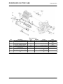
WATER PUMP
pos.
1
2
3
4
5
Description
Clutch side cover fastener screw
Fastener screw for Pump Cover /
Clutch side cover
Screw fastening Pump Cover /
Clutch Cover / clutch side crankcase
half
Nut fastening pump drive input gear
on shaft
Water pump rotor
Type
M6
M6
Quantity
13
3
Torque
13 Nm (9.59 lbf ft)
13 Nm (9.59 lbf ft)
Notes
-
M6
2
13 Nm (9.59 lbf ft)
-
M6
1
12 Nm (8.85 lbf ft)
Loctite 244
-
1
4.50 Nm (3.32 lbf ft)
-
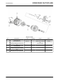
Type
M6
M6
Quantity
11
3
Torque
13 Nm (9.59 lbf ft)
13 Nm (9.59 lbf ft)
Notes
-
M6
2
13 Nm (9.59 lbf ft)
-
M6
1
12 Nm (8.85 lbf ft)
-
M6
1
1
-
M6
M6x10
3
1
4.50 Nm (3.32 lbf ft)
8-10 Nm (5.90-7.38 lbf
ft)
12 Nm (8.85 lbf ft)
6.5 Nm (4.79 lbf ft)
OPTION 02
WATER PUMP
pos.
1
2
3
4
5
6
7
8
Description
Clutch side cover fastener screw
Fastener screw for Pump Cover /
Clutch side cover
Screw fastening Pump Cover /
Clutch Cover / clutch side crankcase
half
Nut fastening water pump drive gear
sprocket
Water pump rotor
Screw fastening chain tensioner slider to water pump
Water pump support fixing screw
Water pump support plug
CHAR - 52
3M SCOTCH GRIP
2353
DORSODURO FACTORY ABS
Characteristics
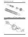
IGNITION
pos.
1
2
3
3
4
5
6
7
8
9
-
Description
Spark plug
Freewheel Ring fastener screw
Screw fixing rotor - Crankshaft - (12
mm - 0.47 in)
Screw fixing rotor - Crankshaft - (14
mm - 0.55 in)
Screw fastening Stator / Flywheel
Cover
Screw fastening pick-up / Flywheel
cover
Flywheel cover fastener screw
Screw fastening starter motor bracket to crankcase
Crankshaft access cap
Retainer plate fastener screw
Screw fastening bracket to starter
motor
Pick-up cable retainer screw
Type
M6
M12x1.25
Quantity
2
6
1
Torque
13 Nm (9.59 lbf ft)
14 Nm (10.33 lbf ft)
130 Nm (95.88 lb ft)
Notes
Loctite 242
-
M12x1.25
1
-
M6
3
190-200 Nm
(140.14-147.51 lb ft)
9 Nm (6.64 lb ft)
M5
2
3.50 Nm (2.58 lbf ft)
-
M6
M6
10
2
13 Nm (9.59 lb ft)
13 Nm (9.59 lbf ft)
-
M6
M6x14
1
1
2
4 Nm (2.95 lb ft)
8 Nm (5.90 lbf ft)
13 Nm (9.59 lbf ft)
-
M5
2
3 Nm (2.21 lbf ft)
-
-
CHAR - 53
DORSODURO FACTORY ABS
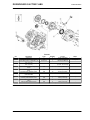
Characteristics
CRANKCASE 1
pos.
1
2
3
4
Description
Bearing retainer fastener screw
Piston oil jet fastener screw
Tapered plug for crankshaft main
bearing lubrication
Calibrated Brass dowel fixed to complete crankcase
CHAR - 54
Type
M6
M5
M8x1
Quantity
3
2
4
Torque
10 Nm (7.38 lbf ft)
5.50 Nm (4.06 lbf ft)
15 Nm (11.06 lbf ft)
Notes
Loctite 270
Loctite 242
-
M8
2
5.50 Nm (4.06 lbf ft)
-
DORSODURO FACTORY ABS
Characteristics
CRANKCASE 2
pos.
1
2
3
4
Description
Engine speed sensor fixing screw
Screw fastening flywheel side /
clutch side crankcase halves
Screw fastening flywheel side /
clutch side crankcase halves
Special calibrated screw for gearbox
lubrication
Type
M6
M6
Quantity
1
8
Torque
13 Nm (9.59 lbf ft)
13 Nm (9.59 lbf ft)
Notes
Loctite 243
-
M8
9
29 Nm (21.39 lbf ft)
-
-
1
18 Nm (13.28 lbf ft)
-
Overhaul data
Assembly clearances
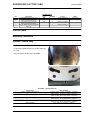
Cylinder - piston assy.
The pistons are available in four size types (A, B,
C, D) to be coupled to the four cylinder types (A,
B, C, D).
Only one type of piston ring is available.
CYLINDER - PISTON COUPLING
Specification
Piston - cylinder coupling Type A
Piston - cylinder coupling Type B
Piston - cylinder coupling Type C
Piston - cylinder coupling Type D
Fitting clearance
Desc./Quantity
Cylinder: 91.990 - 91.977 mm (3.6216 - 3.6219 in)
Piston: 91.933 - 91.940 mm (3.6217 - 3.6197 in)
Cylinder: 91.997 - 92.004 mm (3.6219 - 3.6222 in)
Piston: 91.940 - 91.947 mm (3.6197 - 3.6199 in)
Cylinder: 92.004 - 92.011 mm (3.6222 - 3.6225 in)
Piston: 91.947 - 91.954 mm (3.6199 - 3.6202 in)
Cylinder: 92.011 - 92.018 mm (3.6225 - 3.6227 in)
Piston: 91.954 - 91.961 mm (3.6202 - 3.6205 in)
0.050 - 0.064 mm (0.00197 - 0.00252 in)
CHAR - 55
DORSODURO FACTORY ABS
Characteristics
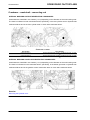
Crankcase - crankshaft - connecting rod
INTERNAL MARKING ON FIRST GENERATION CRANKCASES
Crankcases are classified in two classes (1 or 2) depending on the diameter of the main bearing seat.
The class is indicated on both crankcase halves, specifically, in the rear cylinder area on flywheel side
crankcase halves and in the front cylinder area on clutch side crankcase halves.
CRANKCASE CLASSES
Specification
Crankcase class 1
Crankcase class 2
Desc./Quantity
Bushing seat diameter: 53.954 - 53.960 mm (2.1241 - 2.1244
in)
Bushing seat diameter: 53.960 - 53.966 mm (2.1244 - 2.1246
in)
INTERNAL MARKING ON SECOND GENERATION CRANKCASES
Crankcases are classified in two classes (1 or 2) depending on the diameter of the main bearing seat.
The class is indicated on both crankcase halves, specifically, in the starter gear area on flywheel side
crankcase halves and in the gearbox control mechanism area on clutch side crankcase halves.
See also
Removing the flywheel cover
CHAR - 56
DORSODURO FACTORY ABS
Characteristics
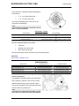
There are three crankshaft classes selectable for
each bearing:
•
4 - 5 - 6 for the flywheel side;
•
7 - 8 - 9 for the clutch side;
The class is stamped on the outer face of the
crankshaft counterweight.
NOTE
TWO DIFFERENT CRANKSHAFT CLASSES MAY BE POSSIBLE ON THE TWO BEARINGS.
CRANKSHAFT CLASSES
Specification
Crankshaft classes 4 - 7
Desc./Quantity
Main journals - diameter: 49.978 - 49.984 mm (1.9676 - 1.9679
in)
Main journals - diameter: 49.972 - 49.978 mm (1.9674 - 1.9676
in)
Main journals - diameter: 49.990 - 49.984 mm (1.9681 - 1.9679
in)
Crankshaft classes 5 - 8
Crankshaft classes 6 - 9
Once the categories below are checked:
•
crankcase
•
flywheel side main journal
•
clutch side main journal
choose the bushings used for assembly from the following table
See also
Removing the flywheel cover
MAIN BUSHINGS
Main journal
Class 4 main journal (l.v.)
Class 5 main journal (l.v.)
Class 6 main journal (l.v.)
Class 7 main journal (l.f.)
Class 8 main journal (l.f.)
Class 9 main journal (l.f.)
Crankcase class 1
Semi-bushing type A (red)
Semi-bushing type B (blue)
Semi-bushing type E (green)
Semi-bushing type A (red)
Semi-bushing type B (blue)
Semi-bushing type E (green)
Crankcase class 2
Semi-bushing type B (blue)
Semi-bushing type C (yellow)
Semi-bushing type A (red)
Semi-bushing type B (blue)
Semi-bushing type C (yellow)
Semi-bushing type A (red)
Crankcase class (internal marking on first generation crankcases)
Two different crankcase classes (A or B) are available, selected in relation to the centre-to-centre
distance between the primary reduction gears.
The class is indicated on the clutch side crankcase
half near the front cylinder area.
NOTE
IN THE EVENT OF CRANKCASE REPLACEMENT, THE PRIMARY REDUCTION GEAR IS SUPPLIED READY MESHED.
CHAR - 57
DORSODURO FACTORY ABS
Characteristics
CRANKCASE CLASSES 01
Specification
Crankcase class A
Desc./Quantity
Centre-to-centre distance: 110.50 - 110.54 mm (4.3504 4.3519 in)
Centre-to-centre distance: 110.46 - 110.50 mm (4.3488 4.3504 in)
Crankcase class B
See also
Removing the flywheel cover
Crankcase class (internal marking on second
generation crankcases)
Two different crankcase classes (A or B) are available, selected in relation to the centre-to-centre
distance between the primary reduction gears.
The class is indicated on the clutch side crankcase
half, in the gearbox control mechanism area.
NOTE
IN THE EVENT OF CRANKCASE REPLACEMENT, THE PRIMARY REDUCTION GEAR IS SUPPLIED READY MESHED.
CRANKCASE CLASSES 02
Specification
Crankcase class A
Crankcase class B
Class one
Two different pinion classes (A or B) are available,
selected in relation to the centre-to-centre distance between the primary reduction gears.
On class B pinions only, the class is indicated on
the pinion itself.
See also
Removing the flywheel cover
CHAR - 58
Desc./Quantity
Centre-to-centre distance: 110.50 - 110.54 mm (4.3504 4.3519 in)
Centre-to-centre distance: 110.46 - 110.50 mm (4.3488 4.3504 in)
DORSODURO FACTORY ABS
Characteristics
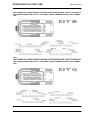
Crankshaft class (crank pin)
There are four different classes of crankshaft available (0, 1, 2, 3), selected in relation to crank pin
diameter.
There are four different classes of crankshaft available (E1, E2, ...) selectable in relation to connecting rod weight.
Key:
* Class according to connecting rod weight.
** Class according to crank pin diameter.
*** Serial number for traceability and indicating date.
SHAFT CATEGORY
Class
Crank pin diameter (mm)
42.000 - 42.006 mm (1.65354 - 1.65377 in)
41.994 - 42.000 mm (1.65330 - 1.65354 in)
41.988 - 41.994 mm (1.65307 - 1.65330 in)
41.982 - 41.988 mm (1.65283 - 1.65307 in)
0
1
2
3
See also
Removing the flywheel cover
Selecting bushings
There is only one dimension class for the connecting rod. As a result, the bushings used must be
selected in accordance with the dimension class of the crank pin.
BUSHINGS
Crank pin diameter
Connecting rod class 1
Semi-bushing type E (green)
Semi-bushing type A (red)
Semi-bushing type B (blue)
Semi-bushing type C (yellow)
Crankshaft class 0
Crankshaft class 1
Crankshaft class 2
Crankshaft class 3
Selecting connecting rods
Not all weight classes are available as spare parts. Only the two most significant weight classes are
available - refer to the following table for selection:
CONNECTING RODS
Class according to crankshaft weight
E1
E2
E3
E4
E5
E6
E7
Original connecting rod class
Brown connecting rod
Blue connecting rod
Yellow connecting rod
Green connecting rod
Pink connecting rod
Black connecting rod
White connecting rod
CAUTION
THE CONNECTING RODS INSTALLED ON THE SAME ENGINE MUST BE OF THE SAME COLOUR
AND MUST USE THE SAME TYPE OF ASSEMBLY WITH THE CRANKSHAFT.
CHAR - 59
DORSODURO FACTORY ABS
Characteristics
WHEN REFITTING, ALSO ENSURE THAT THE SEMI-BUSHINGS ARE ALL OF THE SAME CLASS.
See also
Removing the flywheel cover
Recommended products chart
RECOMMENDED PRODUCTS TABLE
Product
ENI i-RIDE PG 15W-50
Description
Engine oil
AGIP FORK 5W
FUCHS TITAN SAF 1091 (Sachs)
AGIP MP GREASE
AGIP CHAIN LUBE SPRAY
AGIP BRAKE 4
Fork oil (Showa)
Fork oil
Black smooth textured lithium-calcium
soap based grease containing EP (extreme pressure) additives with optimal
water-repellent properties
Spray lubricating grease
Brake fluid
AGIP BRAKE 5.1
Clutch fluid
AGIP PERMANENT SPECIAL
Ethylene glycol-based antifreeze fluid
with organic inhibition additives. Red,
ready to use.
CHAR - 60
Specifications
Use branded oils with performance
equivalent to or exceeding API SJ, JASO
MA - ACEA A3 - JASO MA2 specifications.
SAE 5W
ISO L-X-BCHB 2 - DIN 51 825 KP2K-20
SAE J 1703 -FMVSS 116 - DOT 3/4 - ISO
4925 - CUNA NC 956 DOT 4 synthetic
fluid
FMVSS 116 - DOT 5.1 Non-silicone synthetic fluid
ASTM D 3306 - ASTM D 4656 - ASTM D
4985 - CUNA NC 956-16
INDEX OF TOPICS
SPECIAL TOOLS
S-TOOLS
DORSODURO FACTORY ABS
Special tools
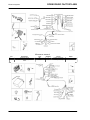
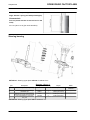
SPECIAL TOOLS
Stores code
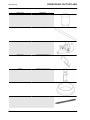
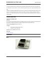
020709Y
Description
Engine support
020710Y
Engine plate
AP8140187
Engine support stand
020711Y
Engine pinion locking
020712Y
Handle for Flywheel cover removal
020713Y
Flywheel extractor
S-TOOLS - 62
DORSODURO FACTORY ABS
Stores code
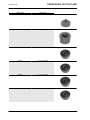
020714Y
Description
Dial gauge mounting
020715Y
Tone wheel removal
9100896
Clutch housing locking tool
020716Y
Connecting rod locking
020470Y
Pin snap ring fitting tool
AP8140302
tool for sealing ring fitting
Special tools
S-TOOLS - 63
DORSODURO FACTORY ABS
Special tools
Stores code
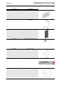
020718Y
Description
Camshaft gear alignment pin
020719Y
Timing pin
020720Y
Timing tool
AP8140179
Valve spring compressor
020721Y
Adaptor for valve removal
020722Y
Guide for oil seal
020376Y
Adapter handle
S-TOOLS - 64
DORSODURO FACTORY ABS
Special tools
Stores code
020629Y
Description
8 mm (0.31 in) guide
020412Y
15-mm Oil seal guide
020439Y
17-mm guide for oil seal
020263Y
Sheath for fitting the driven pulley
020365Y
22 mm (0.87 in) guide
020364Y
25-mm Guide
S-TOOLS - 65
DORSODURO FACTORY ABS
Special tools
Stores code
020483Y
Description
30 mm guide
020441Y
Oil seal punch
020358Y
37 x 40-mm adaptor
020357Y
32 x 35 mm adaptor
020359Y
42 x 47-mm adaptor
020360Y
52 x 55-mm adaptor
S-TOOLS - 66
DORSODURO FACTORY ABS
Stores code
020723Y
Description
Jig for timing overhead camshafts
020724Y
Gear control rod roller cage punch
020661Y
Water pump overall seal replacement kit
020725Y
Punch for water pump overall sealing
020885Y
Water pump oil seal punch
020726Y
Extractor for bushings
020727Y
Punch for bushings
Special tools
S-TOOLS - 67
DORSODURO FACTORY ABS
Special tools
Stores code
AP8140180
Description
Extractor for bushings
8140181
manometer for fuel - oil - compression
pressure
AP8140199
Tool panel
8202222
Generic adhesive film for panel
8140426
Hooks for panel
020880Y
Panel graphics
AP8140149
Protection for fitting operations
S-TOOLS - 68
DORSODURO FACTORY ABS
Special tools
Stores code
AP8140189
Description
Oil seal fitting tool for Ø 43 mm (1.69 in)
orifices
AP8140146
Weight
020889Y
Pumping member ring nut locking spanner
020888Y
Pliers for pre-fill pipe
020884Y
46 mm wrench for steering ring nut
020890Y
Pumping member stanchion support rod
S-TOOLS - 69
INDEX OF TOPICS
MAINTENANCE
MAIN
DORSODURO FACTORY ABS
Maintenance
Maintenance chart
Correct maintenance is fundamental for ensuring the longevity of your vehicle and maintaining optimum
function and performance.
To this end, Aprilia offers a set of checks and maintenance services (at the owner's expense), that are
summarised in the table shown on the following page. Any minor faults must be reported without delay
to an Authorised Aprilia Dealer or Sub-Dealer without waiting until the next scheduled service to
solve it.
All scheduled services must be carried out at the specified intervals and mileage, as soon as the predetermined mileage is reached. Carrying out scheduled services on time is essential for the validity of
your warranty. For further information regarding Warranty procedures and ''Scheduled Maintenance'',
please refer to the ''Warranty Booklet''.
NOTE
CARRY OUT MAINTENANCE OPERATIONS AT HALF THE INTERVALS SPECIFIED IF THE VEHICLE IS USED IN PARTICULAR RAINY OR DUSTY CONDITIONS, OFF ROAD OR FOR TRACK
USE.
NOTE
THE TIMES LISTED ON THE SCHEDULED MAINTENANCE TABLE INCLUDE TIME DEDICATED
TO MANAGEMENT ACTIVITIES.
I: INSPECT AND CLEAN, ADJUST, LUBRICATE OR REPLACE IF NECESSARY
C: CLEAN, R: REPLACE, A: ADJUST, L: LUBRICATE
(1) Check and clean and adjust or replace, if necessary, every 1.000 Km (621.37 mi)
(2) Replace every 2 years
(3) Replace every 4 years
(4) At each engine start
(5) Check every month
(6) Check each time the rear tyre is replaced
(7) Replace at whichever of the following occurs first: 40.000 km (24,854 mi) or 48 months
ROUTINE MAINTENANCE TABLE
km x 1,000
Rear shock absorber
Spark plug
Drive chain (2)
Transmission cables and controls
Steering bearings and steering clearance
Wheel bearings
Control unit diagnosis
Brake discs
Air filter
Engine oil filter
Fork
General vehicle operation
Valve clearance
Cooling system
Braking systems
Light circuit
1
5
10
I
I
I
I
I
I
R
I
I
I
I
15
20
I
R
I
I
I
I
I
I
R
R
I
I
A
I
I
I
25
30
I
35
40
I
R
I
I
I
I
I
I
R
R
I
I
A
I
I
I
MAIN - 71
DORSODURO FACTORY ABS
Maintenance
km x 1,000
Safety switches
Clutch control fluid (2)
Brake fluid (2)
Coolant (2)
Fork oil (7)
Engine oil
Light aiming
Fork oil seals
Flexible coupling (6)
Tyres - pressure/wear (5)
Wheels
Bolts and nuts tightening
Suspension and setting
Fault warning light on instrument panel (4)
Fuel lines (3)
Clutch wear
Brake pad wear
Labour time (minutes)
1
5
10
15
I
I
I
R
I
I
I
I
I
230
I
I
10
I
I
30
I
I
10
20
I
I
I
I
R
I
I
I
I
I
I
I
I
I
I
340
25
30
35
I
I
I
I
10
I
30
I
10
40
I
I
I
I
R
R
I
I
I
I
I
I
I
I
I
I
400
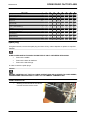
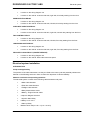
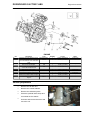
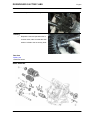
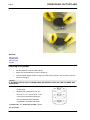
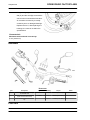
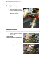
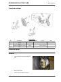
Spark plug
At regular intervals, remove the spark plug and clean off any carbon deposits or replace as required.
CAUTION
ALWAYS REPLACE BOTH SPARK PLUGS EVEN IF ONLY ONE NEEDS REPLACING.
•
Remove the saddle.
•
Remove the lower air deflector.
•
Remove the side fairings.
In order to reach the spark plugs:
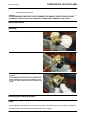
CAUTION
BEFORE CARRYING OUT THE FOLLOWING OPERATIONS AND IN ORDER TO AVOID BURNS,
LEAVE ENGINE AND SILENCER TO COOL OFF TO AMBIENT TEMPERATURE.
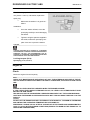
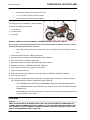
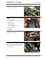
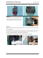
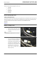
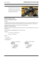
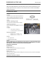
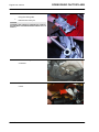
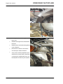
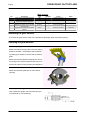
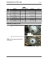
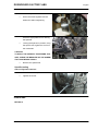
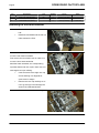
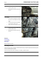
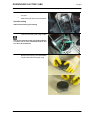
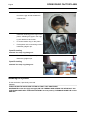
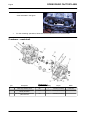
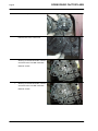
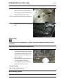
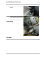
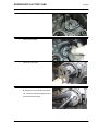
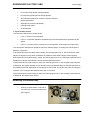
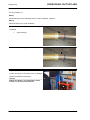
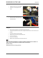
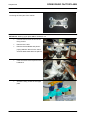
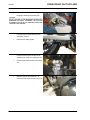
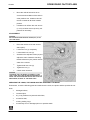
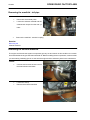
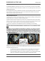
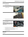
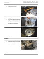
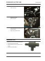
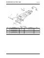
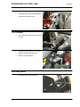
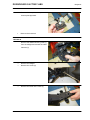
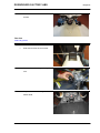
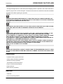
FRONT SPARK PLUG
•
Working on the left side of the vehicle,
unscrew and remove the screw.
MAIN - 72
DORSODURO FACTORY ABS
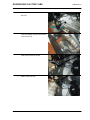
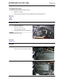
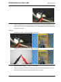
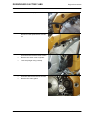
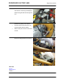
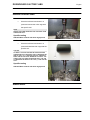
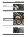
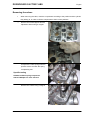
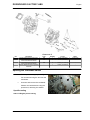
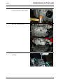
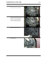
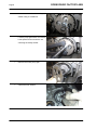
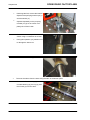
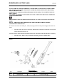
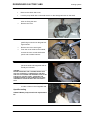
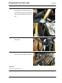
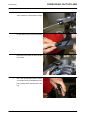
•
Maintenance
Undo and remove the screw, remove
the horn.
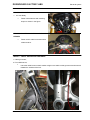
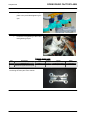
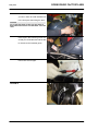
•
Turn the radiator forwards and lower it
to act on the coil.
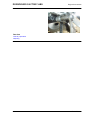
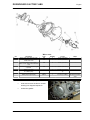
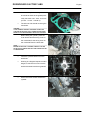
•
Undo and remove the screw.
•
Slide off the front coil.
MAIN - 73
Maintenance
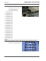
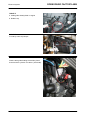
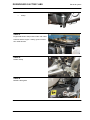
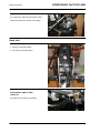
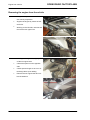
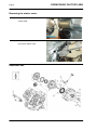
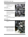
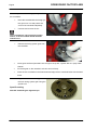
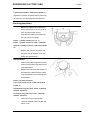
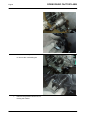
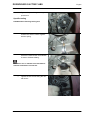
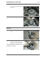
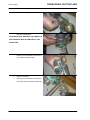
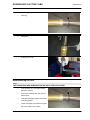
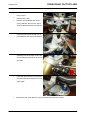
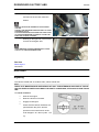
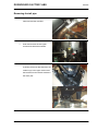
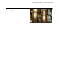
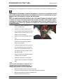
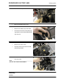
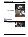
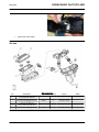
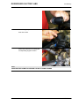
•
DORSODURO FACTORY ABS
Unscrew and remove the front spark
plug.
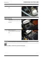
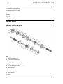
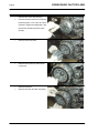
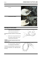
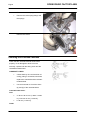
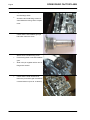
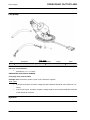
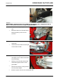
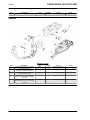
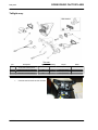
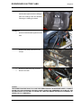
REAR SPARK PLUG
•
Lift the tank.
•
Unscrew and remove the rear coil fixing screw.
•
Slide off the rear coil.
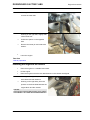
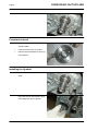
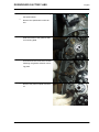
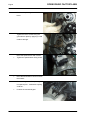
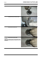
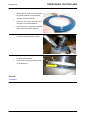
•
Unscrew and slide off the rear spark
plug.
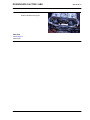
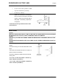
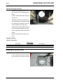
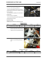
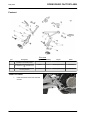
•
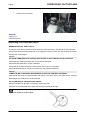
Check the gap between the electrodes with a feeler gauge.
CAUTION
DO NOT ATTEMPT TO READJUST THE ELECTRODE GAP.
MAIN - 74
DORSODURO FACTORY ABS
Maintenance
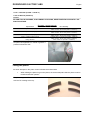
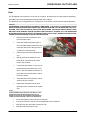
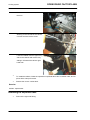
The electrode gap should be between 0.6 ÷ 0.7
mm (0.023 ÷ 0.027 in). Otherwise, replace the
spark plug.
•
Make sure the washer is in good conditions.
Installation:
•
Once the washer is fitted, screw the
spark plug carefully to avoid damaging
the thread.
•
Tighten it using the spanner supplied in
the toolkit, make each spark plug complete 1/2 a turn to press the washer.
CAUTION
TIGHTEN THE SPARK PLUG CORRECTLY, OTHERWISE
THE ENGINE MAY OVERHEAT AND GET IRRETRIEVABLE
DAMAGED. USE ONLY THE RECOMMENDED TYPE OF
SPARK PLUG, OTHERWISE, THE ENGINE DURATION AND
PERFORMANCE COULD BE COMPROMISED.
Locking torques (N*m)
Spark plug 13 Nm (9.59 lbf ft)
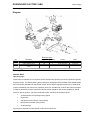
Engine oil
Check
Check the engine oil level frequently.
NOTE
CARRY OUT MAINTENANCE OPERATIONS AT HALF THE INTERVALS SPECIFIED IF THE VEHICLE IS USED IN PARTICULAR RAINY OR DUSTY CONDITIONS, OFF ROAD OR FOR TRACK
USE.
ENGINE OIL LEVEL MUST BE CHECKED WHEN THE ENGINE IS WARM.
IF YOU CHECK LEVEL WHEN THE ENGINE IS COLD, OIL LEVEL COULD TEMPORARILY DROP
BELOW THE "MIN" MARK.
THIS SHOULD NOT BE CONSIDERED A PROBLEM PROVIDED THAT THE ALARM WARNING
LIGHT AND THE ENGINE OIL PRESSURE ICON DO NOT TURN ON SIMULTANEOUSLY ON THE
DISPLAY.
CAUTION
DO NOT LET THE ENGINE IDLE WITH THE VEHICLE AT STANDSTILL TO WARM UP THE ENGINE
AND OBTAIN THE OPERATING TEMPERATURE OF ENGINE OIL.
PREFERABLY CHECK THE OIL AFTER A JOURNEY OF AFTER TRAVELLING APPROXIMATELY
15 Km (10 miles) IN EXTRAURBAN CONDITIONS (ENOUGH TO WARM UP THE ENGINE OIL TO
OPERATING TEMPERATURE).
MAIN - 75
Maintenance
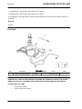
•
Shut off the engine.
•
Keep the vehicle upright with both
DORSODURO FACTORY ABS
wheels on the ground.
•
Check the correct oil level through the
appropriate sight glass on the engine
crankcase.
MAX = maximum level.
MIN = minimum level
•
The oil level is correct when it is close
to the "MAX" reference.
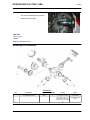
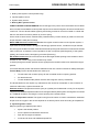
Replacement
Check the engine oil level frequently.
To change the oil:
CAUTION
HOT OIL IS MORE FLUID AND WILL DRAIN OUT MORE EASILY AND COMPLETELY; IDEAL
TEMPERATURE IS REACHED AFTER THE ENGINE HAS RUN FOR ABOUT TWENTY MINUTES.
OIL BECOMES VERY HOT WHEN THE ENGINE IS HOT; BE CAREFUL NOT TO GET BURNED
WHEN CARRYING OUT THE OPERATIONS DESCRIBED BELOW.
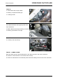
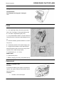
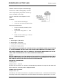
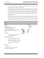
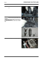
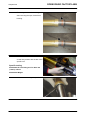
•
Use a cloth to wipe off any mud deposit
on the area next to the filler plug (1).
•
Place a container with + 4000 cm³ (244
cu.in) capacity under the drainage plug
(2).
•
Unscrew and remove the drainage
plug (2).
•
Unscrew and remove the filler plug (1).
•
Drain the oil into the container; allow
several minutes for oil to drain out completely.
•
Replace the sealing washer of the
drainage plug (2).
•
Remove any metal scrap attached to
the drainage plug (2) magnet.
•
Screw and tighten the drainage plug
(2).
MAIN - 76
DORSODURO FACTORY ABS
Maintenance
Locking torques (N*m)
Oil drainage plug - M16x1.5 19 Nm (14.01 lbf ft)
•
Replace the oil filter.
•
Fill up to the right engine oil level by adding recommended engine oil.
See also
Engine
oil filter
Check
Engine oil filter
•
Drain the engine oil.
•
Remove the oil filter.
•
Fit a new engine oil filter.
•
Add engine oil up to the correct level.
CAUTION
NEVER REUSE AN OLD FILTER.
See also
Replacement
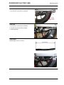
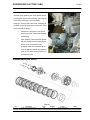
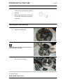
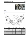
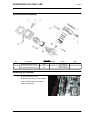
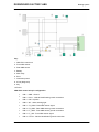
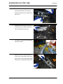
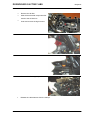
Air filter
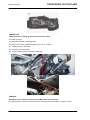
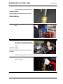
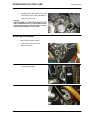
•
Remove the fuel tank.
•
Disconnect the air temperature sensor.
•
Undo and remove the nine screws.
MAIN - 77
Maintenance
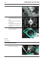
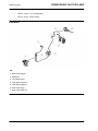
•
DORSODURO FACTORY ABS
Remove the clamp and slide off the
blow-by tube.
•
Remove the filter box cover.
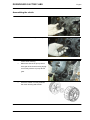
•
Working on both ducts, turn the upper
part of the intake ducts anticlockwise
and remove it.
•
Remove the filtering element.
COVER THE INTAKE DUCTS WITH A CLEAN CLOTH SO
THAT FOREIGN BODIES DO NOT GET INTO THE INLET
DUCTS. UPON REFITTING AND BEFORE PLACING THE
FILTER BOX COVER, MAKE SURE NEITHER THE CLOTH
NOR ANY OTHER OBJECT HAS BEEN LEFT INSIDE THE
FILTER BOX. MAKE SURE THE FILTERING ELEMENT IS
CORRECTLY PLACED SO THAT UNFILTERED AIR DOES
NOT FLOW IN. DO NOT FORGET THAT EARLY WEAR OF
THE PISTON RINGS AND THE CYLINDER CAN BE
CAUSED BY A MALFUNCTIONING OR MISPLACED FILTERING ELEMENT.
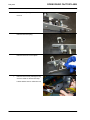
REFITTING
•
Upon refitting, pay attention when inserting intake ducts and check that the bayonet joint is
released once every duct has been inserted and rotated.
MAIN - 78
DORSODURO FACTORY ABS
Maintenance
Checking the valve clearance
The following operation can be carried out also with the engine fitted on the vehicle.
•
Remove both head covers.
CAUTION
WHENEVER THE HEAD COVER IS REMOVED, ALL FOUR RUBBER RINGS AND THE GASKET
SHOULD BE REPLACED.
•
Using a thickness gauge, measure the
distance between the tip of the crankshaft and the valve bowl.
•
Take note of the measurement.
If valve clearance is not within the tolerance range,
adjust as follows:
•
Take the engine to the TDC.
•
Lock the camshafts by using the corresponding timing pins.
Specific tooling
020719Y Timing pin
Characteristic
Intake valve clearance
0.11 - 0.18 mm (0.0043 - 0.0071 in)
Exhaust valve clearance
0.16 - 0.23 mm (0.0063 - 0.0091 in)
•
Remove one camshaft at a time
•
Leave the other camshaft assembled and blocked by means of the timing pin.
CAUTION
IF BOTH CAMSHAFTS ARE REMOVED, THE ENGINE SPINS MAKING TIMING NECESSARY.
•
Remove the bowl tappets and the adjustment shims using a magnet.
NOTE
GREASE THE BOWL TAPPETS AND THE ADJUSTMENT
SHIMS PROPERLY EACH TIME THEY ARE REMOVED.
MAIN - 79
Maintenance
•
DORSODURO FACTORY ABS
Replace calibrated pads with a pad
thick enough to correct the valve clearance previously detected.
•
List of calibrated break pads:
1. Calibrated pad 2.60
2. Calibrated pad 2.65
3. Calibrated pad 2.70
4. Calibrated pad 2.75
5. Calibrated pad 2.80
6. Calibrated pad 2.85
7. Calibrated pad 2.90
8. Calibrated pad 2.95
9. Calibrated pad 3.00
10.Calibrated pad 3.05
11.Calibrated pad 3.10
12.Calibrated pad 3.15
13.Calibrated pad 3.20
14.Calibrated pad 3.25
15.Calibrated pad 3.30
16.Calibrated pad 3.35
17.Calibrated pad 3.40
18.Calibrated pad 2.55
19.Calibrated pad 2.50
20.Calibrated pad 2.45
21.Calibrated pad 2.40
CAUTION
BEFORE REFITTING HEAD COVERS, CLEAN HEAD AND COVER SURFACES CAREFULLY.
•
Apply THREEBOND on the head cover
perimeter along the gasket housing.
MAIN - 80
DORSODURO FACTORY ABS
•
Maintenance
Apply THREEBOND on the head in the
areas indicated in the figure.
See also
Removing the
head cover
MAIN - 81
INDEX OF TOPICS
TROUBLESHOOTING
TROUBL
DORSODURO FACTORY ABS
Troubleshooting
TROUBLESHOOTING PROCEDURE IF THE EFI WARNING LIGHT ON THE INSTRUMENT PANEL
TURNS ON OR IF THERE IS ABNORMAL ENGINE PERFORMANCE
CAUTION
BEFORE CARRYING OUT ANY TROUBLESHOOTING, CAREFULLY READ THE GENERAL TROUBLESHOOTING CONCEPTS FOR ELECTRICAL DEVICES AT THE BEGINNING OF THE CHECK
AND CONTROL SECTION IN THE ELECTRICAL SYSTEM CHAPTER.
•
1 - THE "EFI" WARNING LIGHT IS ON AND THE WORD "SERVICE" IS SHOWN or THE
"EFI" WARNING LIGHT IS FLASHING AND THE WORDS "URGENT SERVICE" ARE
SHOWN or ONE OF THE TWO SITUATIONS TAKES PLACE AND IS SUDDENLY OUT or
THERE IS ABNORMAL ENGINE PERFORMANCE
•
2 - CONNECT TO THE CONTROL UNIT THROUGH NAVIGATOR BY SELECTING "SELFDIAGNOSIS, APRILIA, DORSODURO, 750 i.e."
•
3 - ARE CURRENT- "ATT"- or STORED- "MEM"- ERRORS SHOWN IN THE "ERRORS
DISPLAY" SCREEN PAGE?
YES, go to 4; NO, go to 12.
•
4 - IF THE ERROR IN THE CENTRAL WINDOW IS SELECTED AND "?" IS DISPLAYED,
PRESS THE KEY "?" TO OBTAIN FURTHER INFORMATION ABOUT THE ERROR. THEN
GO TO THE "ELECTRICAL SYSTEM/CHECKS AND CONTROLS" CHAPTER AND READ
THE INFORMATION CONCERNING THE DEFECTIVE COMPONENT
•
5 - ACCORDING TO WHAT IS INDICATED ABOUT THE ERROR/S, PROCEED AS SUGGESTED AND SOLVE THE PROBLEM
•
6 - WAS THE PROBLEM SOLVED BY REPLACING THE MARELLI CONTROL UNIT?
YES, go to 7; NO, go to 8.
•
7 - READ THE ACTIVATION PROCEDURE FOR A NEW CONTROL UNIT ON THE "ELECTRICAL SYSTEM/CHECKS AND CONTROLS/ECU/MARELLI CONTROL UNIT" CHAPTER - END
•
8 - SELECT "ERROR CLEARING" FROM THE "DEVICES ACTIVATION (INJECTOR)"
SCREEN PAGE
•
9 - WAS THE PROBLEM SOLVED BY REPLACING THE THROTTLE GRIP SENSOR
(DEMAND) OR THE THROTTLE BODY?
NO, END; YES, go to 10
•
10 - READ THE RESET PROCEDURE ON THE "ELECTRICAL SYSTEM/CHECKS AND
CONTROLS/THROTTLE GRIP POSITION SENSOR OR THROTTLE BODY" CHAPTER END
•
11 - CHECK IF THERE ARE CURRENT OR STORED ERRORS DETECTED BY THE INSTRUMENT PANEL REFERRING TO THE "DIAGNOSIS" CHAPTER, "INSTRUMENT
TROUBL - 83
Troubleshooting
DORSODURO FACTORY ABS
PANEL ERRORS" SECTION. IF THERE ARE ERRORS PRESENT, SOLVE THE FAULT
AND SELECT "CLEAR ERRORS"; IF THERE ARE NO ERRORS PRESENT, go to 12
•
12 - IN THE "ENGINE PARAMETER READING" SCREEN PAGE, DOES THE "AIR TEMPERATURE" PARAMETER INDICATE A VALUE EQUIVALENT TO ROOM TEMPERATURE?
YES, go to 13; NO, note A
•
13 - IN THE "ENGINE PARAMETER READING" SCREEN PAGE, DOES THE ENGINE
TEMPERATURE PARAMETER WITH COLD ENGINE INDICATE A VALUE SIMILAR TO
THAT OF THE AIR TEMPERATURE PARAMETER? AFTER STARTING THE ENGINE,
DOES THE PARAMETER INCREASE GRADUALLY INDICATING A CORRECT VALUE?
YES, go to 14; NO, note B
•
14 - IN THE "ENGINE PARAMETER READING" AND THE "LAMBDA SENSOR CORRECTION" SCREEN PAGES, WITH ENGINE AT IDLE AND ENGINE TEMPERATURE AT >
90°C, DOES THE VALUE VARY WITHIN THE 0.9 - 1.1 RANGE?
YES, go to 15; NO, note C
•
15 - IN THE "ENGINE PARAMETER READING" SCREEN PAGE AND WITH ENGINE AT
IDLE, ARE "FRONT THROTTLE CORRECTION PARAMETERS" OR "REAR THROTTLE
CORRECTION" WITHIN THE (-0.4° - +0.4°) RANGE? AND IN THE SAME SCREEN PAGE,
ARE THE "FRONT THROT., POT. 1 (DEGREES)" AND " "REAR THROT., POT. 1 (DEGREES)", WITH ENGINE AT IDLE, > OR = A 0.5°? CAUTION: THE DIFFERENCE OF THE
THROTTLE CORRECTION VALUES BETWEEN THE REAR AND FRONT CYLINDER
MUST NOT BE >0.4°
YES, go to 16; NO, note D
•
16 - CHECK: ENGINE SPEED SENSOR, FUEL PRESSURE, INJECTORS (MECHANICAL
OPERATION), COILS (SPARK), ENGINE MECHANICS - END
Note A: SEE THE "ELECTRICAL SYSTEM/CHECKS AND CONTROLS/AIR TEMPERATURE SENSOR" CHAPTER.
Note B: SEE THE "ELECTRICAL SYSTEM/CHECKS AND CONTROLS/ENGINE TEMPERATURE
SENSOR" CHAPTER.
Note C: SEE THE "ELECTRICAL SYSTEM/CHECKS AND CONTROLS/LAMBDA PROBE" CHAPTER.
Note D: SEE THE "ELECTRICAL SYSTEM/CHECKS AND CONTROLS/THROTTLE BODY" CHAPTER.
See also
Checks and inspections
TROUBL - 84
DORSODURO FACTORY ABS
Troubleshooting
Engine
The engine does not start
THE ENGINE DOES NOT START
CAUTION
NAVIGATOR SHOULD BE WORKING PROPERLY AND UPGRADED.
CAUTION
BEFORE ANY TROUBLESHOOTING, MAKE SURE THAT:
1) BATTERY VOLTAGE IS ABOVE 12V;
2) THE MAIN 30A FUSE IS NOT DAMAGED AND IS ADEQUATELY FITTED;
3) SECONDARY FUSES ARE NOT DAMAGED AND ARE ADEQUATELY FITTED.
NOTE
THE RELAY NUMBER SPECIFIED REFERS TO THE WIRING DIAGRAM. THE POSITION OF THE
RELAY ON THE VEHICLE IS INDICATED IN THE "ELECTRICAL SYSTEM/COMPONENT LAYOUT/
RELAY LAYOUT" CHAPTER.
•
1 - WITH THE KEY TURNED TO "ON", THE INSTRUMENT PANEL LIGHTS UP BUT NO
FAILURE INDICATION IS SHOWN. IS THE FUEL PUMP ACTIVATED?
YES, go to 27; NO, go to 2
•
2 - DOES NAVIGATOR COMMUNICATE WITH THE CONTROL UNIT?
YES, go to 3; NO, go to 4
•
3 - ACTIVATE ONE INJECTOR BY MEANS OF NAVIGATOR ("DEVICES ACTIVATION"
SCREEN PAGE, INJECTOR ICON): IS THE INJECTOR ACTIVATED?
YES, go to 17; NO, go to 12
•
4 - WITH THE IGNITION OFF, CHECK FOR VOLTAGE ON THE ORANGE/RED WIRE OF
THE MAIN INJECTION RELAY (POLARISED) 39.
YES, go to 6; NO, go to 5
•
5 - LOCATE THE INTERRUPTION IN THE ORANGE/RED WIRE FROM THE MAIN INJECTION RELAY (POLARISED) 39 TO BATTERY POSITIVE.
•
6 - WITH THE IGNITION ON, CHECK FOR VOLTAGE ON THE GREEN/BLACK WIRE OF
THE MAIN INJECTION RELAY (POLARISED) 39.
YES, go to 8; NO, go to 7
•
7 - LOCATE THE GREEN/BLACK WIRE FROM THE MAIN INJECTION RELAY (POLARISED) 39 TO THE IGNITION SWITCH - END
•
8 - IS THE BLUE CABLE GROUNDED?
YES, go to 10; NO, go to 9
•
9 - RESTORE THE CABLE HARNESS.
•
10 - CHECK IF THERE IS VOLTAGE ON THE RED/BLACK CABLE.
NOT OK, go to 11; OK, go to 12
TROUBL - 85
DORSODURO FACTORY ABS
Troubleshooting
•
11 - REPLACE THE MAIN INJECTION RELAY (POLARISED) 39 - END
•
12 - CHECK FOR VOLTAGE ON THE ORANGE/RED WIRE OF THE AUXILIARY INJECTION RELAY 40.
YES, go to 13; NOT OK, go to 14
•
13 - CHECK IF THERE IS VOLTAGE ON THE YELLOW/PURPLE CABLE.
OK, go to 15; NOT OK, go to 16
•
14 - RESTORE THE CABLE HARNESS - END
•
15 - SET THE KEY TO "OFF" AND THEN "ON": DOES THE VOLTAGE ON THE YELLOW/
PURPLE CABLE REACH APPROX. 1-2V FOR 2 SECONDS?
YES, go to 17; NO, go to 18
•
16 - REPLACE THE AUXILIARY INJECTION RELAY 40- END
•
17 - WITH THE IGNITION OFF, CHECK THE RED/BROWN WIRE FROM THE AUXILIARY
INJECTION RELAY 40 TO THE FUEL PUMP CONNECTOR FOR CONTINUITY AND
GROUND INSULATION.
YES, go to 20; NO, go to 19
•
18 - WHEN THE KEY IS TURNED TO "OFF", CHECK CONTINUITY AND GROUND INSULATION OF THE YELLOW/PURPLE CABLE FROM THE RELAY TO PIN 62, VEHICLE
CONNECTOR.
YES, go to 22; NO, go to 21
•
19 - RESTORE THE CABLE HARNESS.
•
20 - CHECK THERE IS GROUND INSULATION FOR THE BLUE CABLE OF THE PUMP
CONNECTOR.
OK, go to 24; NOT OK, go to 23
•
21 - RESTORE THE CABLE HARNESS - END
•
22 - CHECK THE VEHICLE CONNECTOR.
OK, go to 25; NOT OK, go to 26
•
23 - RESTORE THE CABLE HARNESS - END
•
24 - CHECK THAT THE RESISTANCE OF THE PUMP IS APPROX. 1 OHM. IF THE RESISTANCE IS INCORRECT, REPLACE THE PUMP - END
•
25 - REPLACE THE CONTROL UNIT - END
•
26 - RESTORE THE CABLE HARNESS - END
•
27 - DOES THE MOTOR TURN WHEN THE STARTER BUTTON IS PRESSED?
YES, go to 29; NO, go to 28
•
28 - WHAT DOES THE "START-UP ENABLING SWITCH" STATUS ON NAVIGATOR (DEVICE STATUS/ICON "0/1" SCREEN PAGE) MEAN?
YES, go to 43; NO, go to 64
TROUBL - 86
DORSODURO FACTORY ABS
•
Troubleshooting
29 - CHECK FOR VOLTAGE ON THE BROWN/WHITE WIRE OF STARTER MAINTENANCE RELAY (POLARISED) 37
OK, go to 30; NOT OK, go to 31
•
30 - WITH THE STARTER MAINTENANCE RELAY (POLARISED) 37 DISCONNECTED,
KEEP THE STARTER BUTTON PRESSED AND CHECK THAT A VOLTAGE OF APPROX.
1-2V IS MEASURED ON THE YELLOW/RED WIRES
OK, go to 32; NOT OK, go to 33
•
31 - CHECK FOR CONTINUITY ON THE BROWN/WHITE CABLE
OK, go to 31a; NOT OK, go to 31b
31a - WITH THE LIGHT LOGIC RELAY 7 DISCONNECTED, CHECK THE CONTINUITY BETWEEN
PIN 87 AND PIN 30
OK, go to 31c; NOT OK, go to 31d
31b - RESTORE THE CABLE HARNESS
31c - CHECK CONTINUITY ON GREEN/WHITE CABLE FROM THE LIGHT LOGIC RELAY 7 TO
SECONDARY FUSE B
OK, go to 31e; NOT OK, go to 31f
31d - REPLACE THE RELAY - END
31e - CHECK CONTINUITY ON RED/BLACK CABLE FROM SECONDARY FUSE B THE TO MAIN
INJECTION RELAY 39
OK, go to 4; NOT OK, go to 31g
31f - RESTORE THE CABLE HARNESS
31g- RESTORE THE CABLE HARNESS
•
32 - CHECK CONTINUITY OF PINK/BLACK CABLE FROM STARTER MAINTENANCE
RELAY (POLARISED) 37 TO START BUTTON CONNECTOR
OK, go to 34; NOT OK, go to 35
•
33 - RESTORE THE CABLE HARNESS
•
34 - CHECK THAT THE STARTER MAINTENANCE RELAY (POLARISED) 37 WORKS
CORRECTLY
OK, go to 36; NOT OK, go to 37
•
35 - RESTORE THE CABLE HARNESS
•
36 - CHECK CONTINUITY OF PINK/BLACK CABLE FROM STARTER MAINTENANCE
RELAY (POLARISED) 37 TO PIN14 ON VEHICLE CONNECTOR
OK, go to 38; NOT OK, go to 39
•
37 - REPLACE THE STARTER MAINTENANCE RELAY (POLARISED) 37
•
38 - CHECK THE VEHICLE CONNECTOR (PIN 14)
OK, go to 40; NOT OK, go to 41
TROUBL - 87
DORSODURO FACTORY ABS
Troubleshooting
•
39 - RESTORE THE CABLE HARNESS
•
40 - REFER TO THE CHAPTER ON "ELECTRICAL SYSTEM/CHECKS AND CONTROLS/
ENGINE REVOLUTION SENSOR"; FOLLOW THE TROUBLESHOOTING STEPS IN THE
SECTION REFERRING TO "NAVIGATOR: ELECTRICAL ERRORS".
CAUTION: failure NOT identified, go to 42; failure identified, END
•
41 - RESTORE THE CABLE HARNESS
•
42 - CHECK INJECTORS AND ENGINE FOR CORRECT MECHANICAL OPERATION,
CHECK FUEL CIRCUIT PRESSURE.
•
43 - WHEN THE STARTER BUTTON IS PRESSED, DOES THE VOLTAGE TO THE YELLOW/PINK WIRE OF THE CONTROL RELAY (START LOGIC) 38 CHANGE TO APPROX.
ZERO?
YES, go to 44; NO, go to 45
•
44 - CHECK FOR VOLTAGE ON THE RED/BLACK WIRES OF THE COMMAND RELAY
(START LOGIC) 38
YES, go to 50; NO, go to 51
•
45 - CHECK CONTINUITY AND GROUND INSULATION OF THE YELLOW/PINK CABLE
FROM THE RELAY TO THE ENGINE CONNECTOR (PIN 2)
OK, go to 47; NOT OK, go to 46
•
46- RESTORE THE CABLE HARNESS - END
•
47 - CHECK THE CONTROL UNIT CONNECTOR
OK, go to 49; NOT OK, go to 48
•
48 - RESTORE THE CABLE HARNESS - END
•
49 - REPLACE THE CONTROL UNIT - END
•
50 - WHILE PRESSING THE STARTER BUTTON, DISCONNECT THE CONNECTOR FOR
THE WHITE/SKY BLUE AND WHITE/RED WIRES OF THE STARTER RELAY 34 AND
CHECK FOR VOLTAGE ON YELLOW/RED WIRE OF THE (START LOGIC) CONTROL
RELAY 38
OK, go to 52; NOT OK, go to 53
•
51 - REPLACE THE RELAY - END
•
52 - PRESSING THE STARTER BUTTON, CHECK IF THERE IS VOLTAGE TO THE YELLOW/RED CABLE OF THE START-UP RELAY
OK, go to 54; NOT OK, go to 55
•
53 - REPLACE THE RELAY - END
•
54 - CHECK IF THE BLUE WIRE OF THE STARTER RELAY 34 IS GROUNDED
OK, go to 56; NOT OK, go to 57
TROUBL - 88
DORSODURO FACTORY ABS
Troubleshooting
•
55 - RESTORE THE CABLE HARNESS -END
•
56 - WITH THE IGNITION OFF, CHECK FOR VOLTAGE ON THE REAR RED WIRE (WITH
CAP) OF THE STARTER RELAY 34
OK, go to 58; NOT OK, go to 59
•
57 - RESTORE THE CABLE HARNESS -END
•
58 - WITH THE STARTER BUTTON PRESSED, CHECK FOR VOLTAGE ON THE FRONT
RED WIRE OF THE STARTER RELAY 34
OK, go to 60; NOT OK, go to 61
•
59 - RESTORE THE CABLE HARNESS
•
60 - CHECK FOR CONTINUITY ON THE RED WIRE BETWEEN THE STARTER RELAY
34 AND THE STARTER MOTOR
YES, go to 62; NO, go to 63
•
61 - REPLACE THE STARTER RELAY 34 - END
•
62 - REPLACE THE STARTER MOTOR - END
•
63 - RESTORE THE CABLE HARNESS - END
•
64 - WHAT DOES THE "FALL SENSOR" STATUS ON NAVIGATOR (DEVICE STATUS/
ICON "0/1" SCREEN PAGE) MEAN?
If "NORMAL" is shown, go to 65; If "TIP OVER" is shown, go to 68
•
65 - WITH THE SWITCH SET TO "RUN", WHAT DOES THE "RUN-STOP SWITCH" STATUS ON NAVIGATOR ("DEVICE STATUS/ICON "0/1" SCREEN PAGE) MEAN?
If "RUN" is shown, go to 66; If "STOP" is shown, go to 67
•
66 - USING NAVIGATOR CHECK THAT THE SIDE STAND, NEUTRAL SENSOR AND
CLUTCH SENSOR FUNCTION CORRECTLY; OPERATE ANY DEVICE AND CHECK THE
SUITABLE INDICATION ON THE "DEVICE STATUS/ICON "0/1" SCREEN PAGE
If "MALFUNCTION" is shown, go to 71; If "CORRECT OPERATION" is shown, go to 72
•
67 - REFER TO THE CHAPTER ON "ELECTRICAL SYSTEM/CHECKS AND CONTROLS/
FALL SENSOR; INDICATION ON NAVIGATOR ALWAYS STOP- END
•
68 - IS THE SENSOR VERTICAL?
YES, go to 69; NO, go to 70
•
69 - REFER TO THE CHAPTER ON "ELECTRICAL SYSTEM/CHECKS AND CONTROLS/
FALL SENSOR, INDICATION ON NAVIGATOR ALWAYS TIP OVER - END
•
70 - SET THE SENSOR TO THE CORRECT POSITION - END
•
71 - ACCORDING TO THE FAILURE, REFER TO CHAPTER ON "ELECTRICAL SYSTEM/
CHECKS AND CONTROLS/GEAR IN NEUTRAL SENSOR", or "CLUTCH LEVER SENSOR" or "SIDE STAND SENSOR" - END
TROUBL - 89
Troubleshooting
•
72 - REPLACE THE CONTROL UNIT - END
TROUBL - 90
DORSODURO FACTORY ABS
INDEX OF TOPICS
ELECTRICAL SYSTEM
ELE SYS
DORSODURO FACTORY ABS
Electrical system
ELECTRICAL SYSTEM 1
pos.
1
2
Description
Coil fixing screw
TE screw fastening regulator to
frame
ELE SYS - 92
Type
M6
M6x30
Quantity
2
2
Torque
13 Nm (9.59 lbf ft)
10 Nm (7.37 lbf ft)
Notes
-
DORSODURO FACTORY ABS
Electrical system
ELECTRICAL SYSTEM 2
pos.
1
-
Description
Screw fastening ECU to filter box
base
Starter relay fastener
Type
-
Quantity
4
Torque
2.5 Nm (1.47 lbf ft)
Notes
-
-
2
3 - 4.2 Nm (2.21 - 3.1 lbf
ft)
-
Components arrangement
Key
ELE SYS - 93
Electrical system
DORSODURO FACTORY ABS
1. fall sensor
2. Intake air pressure sensor
3. Intake air temperature sensor
4. Instrument panel
5. Engine control unit
6. Headlamp
7. Start-up relay
8. Front ABS sensor
9. Starter motor
10.Engine revolution sensor
11.Lambda probe
12.Rear ABS sensor
13.Coils
14.Main fuses
15.Hand grip position sensor
16.Main injection relay
17.Throttle control unit
18.Spark plugs
19.Taillight
20.Engine revolution sensor - pick up
21.Gear in neutral sensor
22.ABS control unit (modulator)
23.Engine temperature sensor
24.Secondary fuses
CAUTION
A RELAY CANNOT BE IDENTIFIED BASED ONLY ON THE FOLLOWING INDICATIONS: THIS
SHOULD BE DONE ALSO IDENTIFYING THE COLOUR OF THE RELAY CABLES.
RELAY LAYOUT ON THE WIRING DIAGRAM AND ON THE VEHICLE
LIGHT LOGIC RELAY
•
Location on the wiring diagram: 7
•
Location on the vehicle: under the fuel tank, right side, first relay starting from the rear side.
START-UP RELAY
•
Location on the wiring diagram: 34
•
Location on the vehicle: under the fuel tank, left side, second relay starting from the front.
RETENTION RELAY
•
Location on the wiring diagram: 37
•
Location on the vehicle: under the fuel tank, right side, second relay starting from the front.
CONTROL RELAY
ELE SYS - 94
DORSODURO FACTORY ABS
Electrical system
•
Location on the wiring diagram: 38
•
Location on the vehicle: under the fuel tank, right side, third relay starting from the front.
MAIN INJECTION RELAY
•
Location on the wiring diagram: 39
•
Location on the vehicle: under the fuel tank, left side, third relay starting from the front.
AUXILIARY INJECTION RELAY
•
Location on the wiring diagram: 40
•
Location on the vehicle: under the fuel tank, right side, second relay starting from the front.
FAN CONTROL RELAY
•
Location on the wiring diagram: 41
•
Location on the vehicle: under the fuel tank, left side, first relay starting from the front.
HIGH BEAM LIGHTS RELAY
•
Location on the wiring diagram: 64
•
Location on the vehicle: under the fuel tank, right side, first relay starting from the front.
RECOVERY LOGIC RELAY (URGENT SERVICE)
•
Location on the wiring diagram: 65
•
Location on the vehicle: behind the instrument panel.
Electrical system installation
INTRODUCTION
Scope and applicability
The position of the cable harnesses, how they are fixed to the motorcycle and potential problems are
defined on the following sections in order to reach the objectives of vehicle reliability.
Materials used and corresponding quantities
The electrical system consists of the following cable harnesses and parts:
•
1 Main Cable Harness
•
1 Filter Box Cable Harness
•
1 Taillight Cable harness
•
1 Relay-Starter Motor Cable
•
1 Battery - Engine Ground Cable
•
2 Caps for Magura Switches
•
1 Injection Main Relay
•
6 Relays 12 V / 30 A
•
1 Start-up Relay
•
Medium black clamps 178 x 4 (7.01 x 0.16 in)
ELE SYS - 95
Electrical system
•
Small black clamps 98 x 2.5 (3.86 x 0.01 in)
•
1 10-cm (3.94 in) spiral for start-up cable
•
1 Pick-Up divider cable harness (if fitted)
DORSODURO FACTORY ABS
Motorcycle division
The wiring timing is subdivided in three essential
sections, as indicated in the figure.
1. Front section
2. Central section
3. Rear part
SPECIAL CHECKS FOR THE CORRECT CONNECTION AND LAYING OF CABLES
Carry out the checks described below once the electrical system is refitted, connectors reconnected and clamps and retainers restored.
•
Check the connector block for connections and correct tightening in the following connectors.
1. Instrument panel connector: FRONT SECTION.
2. Handgrip sensor connectors: CENTRAL SECTION, TABLE G
3. Pick Up Connector: CENTRAL SECTION.
4. Side Stand Switch Connector: CENTRAL SECTION, TABLE C.
5. Regulator Connector: CENTRAL SECTION, TABLE O.
6. Front cylinder coil and rear cylinder coil connectors.
7. Filter Housing Connectors.
8. ECU and Ground Lead Connectors for the filter casing: CENTRAL SECTION, TABLE C.
9. Fuel Pump Connector.
10.Key Connector - Right Light Switch Connectors - Left Light Switch Connectors: Connectors inside
the housing behind the radiator: FRONT SECTION, TABLE B.
•
THE CONNECTORS LISTED ARE CONSIDERED CRITICAL IN COMPARISON WITH
ANY OTHER BECAUSE THE VEHICLE WILL STOP IF THEY ARE ACCIDENTALLY DISCONNECTED.
•
Undoubtedly the connection of the rest of connectors is also important and essential for the
correct operation of the vehicle.
Front side
CAUTION
ONCE THE ELECTRICAL SYSTEM IS REFITTED, THE CONNECTORS RECONNECTED AND
CLAMPS AND RETAINERS RESTORED, CARRY OUT THE CHECKS INDICATED UNDER "SPECIAL CHECKS FOR THE CORRECT CONNECTION AND LAYING OF CABLES" IN THE "ELECTRICAL SYSTEM INSTALLATION" SECTION.
ELE SYS - 96
DORSODURO FACTORY ABS
Electrical system
TABLE A - RECOVERY
1. 12V 30A Relay
•
Fasten cable harness with retaining
straps as shown in the figure.
TABLE B - FASTENING SWITCH CABLE HARNESSES
•
Fasten switch cable harnesses with a
rubber retainer.
TABLE C - FRONT ABS SENSOR FASTENER
1. Cable grommets;
2. Front ABS sensor;
•
Leave the cable loosen so that it makes a slight curve and the cable grommet must be turned
towards the outside of the fork.
ELE SYS - 97
Electrical system
DORSODURO FACTORY ABS
TABLE D - Lay the cable as shown and fasten it with a 2.5x160 clamp
TABLE E - Fasten with a 2.5x160 clamp
Central part
CAUTION
ONCE THE ELECTRICAL SYSTEM IS REFITTED, THE CONNECTORS RECONNECTED AND
CLAMPS AND RETAINERS RESTORED, CARRY OUT THE CHECKS INDICATED UNDER "SPECIAL CHECKS FOR THE CORRECT CONNECTION AND LAYING OF CABLES" IN THE "ELECTRICAL SYSTEM INSTALLATION" SECTION.
TABLE A - MAIN CABLE HARNESS LAYING
•
View of main cable harness laying
without airbox.
ELE SYS - 98
DORSODURO FACTORY ABS
Electrical system
TABLE B - CABLE HARNESS FOR RELAY UNIT
The shortest cables must be connected to the
three closest relays
TABLE C
To lay the auxiliary fuses box under the airbox:
•
slide off the protection cap.
•
reinsert it observing the correct poles
1. Side stand switch
2. Neutral switch
3. Horn
4. Control unit connectors
TABLE D
The generator output cable must be laid behind the
thermostatic valve, under the airbox.
ELE SYS - 99
Electrical system
TABLE E
5. Cable guide already fitted on engine
6. Rubber cap
TABLE F
4.5x180 (0.18x7.08) Clamps
TABLE G
Plastic cable guide holding the auxiliary fuses
branch and the cylinder coil cable 1 (horizontal).
ELE SYS - 100
DORSODURO FACTORY ABS
DORSODURO FACTORY ABS
Electrical system
TABLE H
4.5x290 (0.18x11.42) Clamp
TABLE I
1. 12V / 30A Fan relay
2. Relay with ignition maintenance diode (service) 12V / 20A
3. Main injection relay
4. Resistance module
5. High- and low-beam lights relay
6. Auxiliary injection relay
7. Control relay
8. Logic relay
TABLE J
4.5x290 (0.18x11.42) Clamp
TABLE K
Plastic cable guide that holds the lambda probe
branch, the rear stop switch branch and the rear
wheel speed sensor.
ELE SYS - 101
Electrical system
TABLE L
First of all connect the light switches connectors
and the key switch inside the rubber cap and position the latter as in the figure, then the Demand
Master (BLUE tape) connector and then the "regulator" connector.
9. Regulator connector
10. Rubber cap that hosts light switch and key
switch connectors.
11. Demand 1 Master Connector
TABLE M
The clamp holds the cables going out from the light
switches and the immobilizer aerial cable going
out from the key switch.
4.5x180 (0.18x7.08) Clamp
TABLE N
2.5x160 (0.10x6.30) Clamp
TABLE O
12. Cable grommet
13. 2.5x98 (0.10x3.86) Clamps
14. 4.5x290 (0.18x11.42) Clamps
ELE SYS - 102
DORSODURO FACTORY ABS
DORSODURO FACTORY ABS
Electrical system
TABLE O1
•
Clamp.
TABLE P
Engine attachment clamps that coil the main cable
harness and the engine - battery ground connection cable harness.
TABLE Q
Rubber clamp
TABLE R
Metallic cable guide
ELE SYS - 103
Electrical system
DORSODURO FACTORY ABS
TABLE S
15. Side stand switch output sheath
16. Battery compartment bleed pipe
17. Cable grommet
TABLE T
The cables fastened to the engine ground must
face downwards.
18. Main cable harness engine earthing on the left
19. Battery ground lead on the right
TABLE U
2 4.5x180 (0.18x7.08) Clamps
TABLE V - LAMBDA PROBE
Place the cable harness of the lambda probe in the cable grommet on the clutch crankcase.
20. Fasten the cable harness to the chassis with the clamp.
21. Place the cable harness of the lambda probe behind the cable grommet on the clutch crankcase.
ELE SYS - 104
DORSODURO FACTORY ABS
Electrical system
TABLE Z
Connector insertion on Demand and secondary lock closing
TABLE ZA-ZB
Tables with tips on filter box cable harness fitting.
ELE SYS - 105
Electrical system
DORSODURO FACTORY ABS
TABLE ZC-ZD
Tables with tips for fitting ground lead and start-up cable
22. Cable grommet
23. ABS cable harness connecting cable
24. Starter motor cable coiled with pigtail wire L=10 cm (3.93 in)
25. 4.5x290 (0.18x11.42) Clamp
26. 2.5x160 (0.10x6.30) Clamp
ZD - engine- battery ground connection cable path
TABLE ZE
Procedure for the correct insertion of the ABS control unit connector
The initial position of the lever that couples the connector must be as shown in figures 1 and 2
ELE SYS - 106
DORSODURO FACTORY ABS
Electrical system
TABLE ZF
Place the connector on the opposite side of the
control unit and lower the driving lever until the
"click" that signals the end of the stroke is heard
TABLE ZG
When the connector is fully inserted, the distance between the connector and the ABS control unit must
be 7.5 mm (0.29 in).
If the initial position of the connector and the driving lever is not as shown in figure ZE, the connector
will not get properly coupled and the distance measured will be longer (12 mm approx. (0.47 in)).
In this case, repeat the operation as described in the ZF-ZG picture.
It is advisable to create a template to check the correct connector insertion.
ELE SYS - 107
Electrical system
TABLE ZH
27. Fasten the cable harness with a clamp.
Insert the housing as shown in the figure.
Back side
TABLE A - Taillight cable harness fitting
1. 2.5x98 (0.10x3.86) Clamp
2. 4.5x180 (0.18x7.08) Clamp
TABLE B - SPEED SENSORS / FRONT AND
REAR WHEEL ABS FITTING
TABLE B1
2.5x160 mm (0.01x6.30 in) Clamps
ELE SYS - 108
DORSODURO FACTORY ABS
DORSODURO FACTORY ABS
Electrical system
TABLE B1/A
3. 2.5x160 mm (0.01x6.30 in) Clamps
TABLE B2
4. 2.5x160 mm (0.01x6.30 in) Clamps
5.4.5x180 mm (0.18x7.08 in) Clamps
6. Cable grommet
TABLE B2/A
Spiral length 110 mm (4.33 in)
ELE SYS - 109
Electrical system
TABLE B3
Cable guide
TABLE B4
2.5x160 mm (0.1x6.30 in) Clamps
ELE SYS - 110
DORSODURO FACTORY ABS
DORSODURO FACTORY ABS
Electrical system
General wiring diagram
key:
1. MULTIPLE CONNECTORS
2. FRONT RIGHT TURN INDICATOR
3. COMPLETE HEADLAMP
4. TAIL LIGHT BULB
5. TWIN HIGH-/LOW BEAM BULB
6. FRONT LEFT TURN INDICATOR
7. LOGIC RELAY WITH N.C. MATING
8. CLUTCH SWITCH
9. HORN
10.Left light switch
11.INSTRUMENT PANEL
12.Right light switch
ELE SYS - 111
Electrical system
13.OIL PRESSURE SENSOR
14.INSTRUMENT PANEL DIAGNOSIS
15.SIDE STAND SWITCH
16.ECU AND ABS DIAGNOSIS
17.IMMOBILIZER AERIAL
18.IGNITION SWITCH
19.REAR LEFT TURN INDICATOR
20.Rear right turn indicator
21.LICENSE PLATE LIGHT BULB
22.23.COMPLETE TAILLIGHT (WITH LED)
24.REAR STOP SWITCH
25.FRONT STOP SWITCH
26.SPEED SENSOR
27.Fall sensor
28.NEUTRAL SENSOR
29.TIMING SENSOR (OPTIONAL)
30.Secondary fuses
31.Flywheel
32.Voltage regulator
33.STARTER MOTOR
34.START-UP RELAY
35.MAIN FUSE
36.BATTERY
37.START-UP MAINTENANCE RELAY
38.CONTROL RELAY (START-UP LOGIC)
39.MAIN INJECTION RELAY (POLARISED)
40.AUXILIARY INJECTION RELAY
41.FAN
42.FAN CONTROL RELAY
43.FUEL LEVEL SENSOR
44.FUEL PUMP
45.REAR CYLINDER COIL
46.FRONT CYLINDER COIL
47.REAR CYLINDER SPARK PLUG
48.FRONT CYLINDER SPARK PLUG
49.INTAKE AIR TEMPERATURE SENSOR
50.Water Temperature Sensor
ELE SYS - 112
DORSODURO FACTORY ABS
DORSODURO FACTORY ABS
Electrical system
51.LAMBDA PROBE
52.PURGE VALVE (OPTIONAL)
53.REAR CYLINDER PRESSURE SENSOR
54.FRONT CYLINDER PRESSURE SENSOR
55.REAR CYLINDER INJECTOR
56.FRONT CYLINDER INJECTOR
57.EFG 1X THROTTLE CONTROL UNIT
58.REAR CYLINDER THROTTLE
59.FRONT CYLINDER THROTTLE
60.DEMAND CONTROL UNIT
61.PICK-UP
62.ECU
63.64.LOW-/HIGH- BEAM / PASSING LIGHT RELAY WITH N.C. MATTING
65.RECOVERY LOGIC RELAY (URGENT SERVICE)
66.PROTECTION RESISTANCES
67.ABS CONTROL UNIT
68.FRONT ABS SENSOR
69.REAR ABS SENSOR
70.ABS CONTROL UNIT FUSE
Colour key:
Ar Orange
Az Sky blue
B Blue
Bi White
G Yellow
Gr Grey
M Brown
N Black
R Red
Ro Pink
V Green
Vi Purple
Conceptual diagrams
Checks and inspections
GENERAL CONCEPTS OF ELECTRICAL TROUBLESHOOTING
ELE SYS - 113
Electrical system
DORSODURO FACTORY ABS
THE CONNECTION DIAGRAMS ARE IN THE ELECTRICAL SYSTEM SECTIONS; PAY ATTENTION
TO THESE DIAGRAMS AS THEY SHOW THE CONNECTOR/COMPONENT AS VIEWED FROM
THE CABLE HARNESS SIDE, THAT IS LOOKING AT THE CABLES WHEN GOING OUT OF THE
"MAIN" CABLE HARNESS AND INTO THE CONNECTOR/COMPONENT.
CAUTION
BEFORE CARRYING OUT ANY TROUBLESHOOTING PROCEDURE ON THE VEHICLE, CHECK
THAT THE BATTERY VOLTAGE IS ABOVE 12V.
CONNECTOR CHECK PROCEDURE
The procedure includes the following checks:
1. Observation and check of the connector correct
position on the component or on the coupling connector, making sure that the locking catch is released.
2. Observation of the terminals on the connector:
no rust marks or dirt should be present and it is
important to check terminal correct positioning on
the connector (i.e., all terminals aligned at the
same depth) and terminal integrity (i.e., that terminals are not loose, open/bent, etc.). For connectors whose terminals are not visible (e.g. Marelli
control unit) use a metal cable of suitable diameter
and introduce it carefully in the connector slot at
the same depth as for the other terminals of the
connector.
CAUTION
IN CASE OF TEMPORAL MALFUNCTIONING, CARRY OUT
ALL DUE CHECKS LOOKING FOR FAULT BY MOVING
SLIGHTLY THE CABLE HARNESS BEING INSPECTED.
3. Pulling the cables slightly from the back of the connector in order to check the correct position of
terminals on the connector and of the cable on the terminal.
CONTINUITY check
Check goal: this control is to check that there are not any circuit interruptions nor excessive resistance,
for instance caused by rust, on the two terminals being inspected.
Tester: set the tester on the "continuity" symbol and place the tester probes on the two circuit ends:
the tester emits a sound signal only if there is continuity; the tester can also be set to the Ohm symbol
to check that the circuit resistance is null or a few tenths of an Ohm.
CAUTION: THE CIRCUIT SHOULD NOT BE ENERGISED, OTHERWISE THE TEST IS IRRELEVANT.
GROUND CONNECTION check
ELE SYS - 114
DORSODURO FACTORY ABS
Electrical system
Check goal: this control is to check if a cable or a circuit is in contact with the vehicle ground (-)
connection.
Tester: set the tester on the "continuity" symbol and place one tester probe on the vehicle ground
connection (or on the battery - terminal) and the other probe on the cable being inspected: the tester
sends out a sound signal only if there is continuity. The tester can also be set to the Ohm symbol to
check that the circuit resistance is null or a few tenths of an Ohm.
CAUTION! IF THERE IS A GROUND CONNECTION COMING FROM THE CONTROL UNIT, MAKE
SURE THAT DURING THE TEST THE CONTROL UNIT IS GROUND CONNECTED TO THE CIRCUIT.
VOLTAGE check
Check goal: this control is to check if a cable is energised, i.e. if it receives power supply from the
battery or the control unit.
Tester: set the tester on the direct current symbol and place the tester red probe on the cable being
inspected and the black probe on the vehicle ground connection (or on the battery - terminal).
CAUTION
IN CASE OF TEMPORAL MALFUNCTIONING, CARRY OUT ALL DUE CHECKS LOOKING FOR
FAULT BY MOVING SLIGHTLY THE CABLE HARNESS BEING INSPECTED.
Dashboard
In case the EFI warning light turns on and the words SERVICE or URGENT SERVICE are shown on
the display, due to an error detected in the injection ECU, the malfunction indication will be deactivated
only after the vehicle has been used for a pre-set number of minutes of operation. However, even though
the malfunction is no longer present and the control unit considers the error no longer current but memorised (MEM error indication on Navigator), the instrument panel may keep showing there is an error
present.
Diagnosis
An access code is required to enter this menu which controls the diagnosis function:
•
ENTER SERVICE CODE
This is a 5-digit code, fixed for each vehicle. For these vehicles, the code is:
98789
If the code is incorrect, the following message is displayed:
•
INCORRECT CODE
and the instrument panel goes back to the main menu. Otherwise, the following menu is displayed:
•
Exit
•
ECU diagnosis
•
INSTRUMENT PANEL ERRORS
ELE SYS - 115
Electrical system
•
Error Clearing
•
VEHICLE SERVICING RESET
•
Update
•
CHANGE KEYS
•
KM / MILES
DORSODURO FACTORY ABS
ECU diagnosis
In this mode a chart is displayed showing potential
errors in the control unit.
IT IS NECESSARY TO REFER TO THE ERROR
INDICATIONS GIVEN BY NAVIGATOR FOR
THIS VEHICLE.
The instrument panel does not keep all previous errors stored in its memory.
INSTRUMENT PANEL ERRORS
In this mode, a chart is displayed showing potential
errors in the immobilizer and the sensors connected to it.
Instrument panel errors
In this mode, a chart is displayed showing potential errors in the immobilizer and the sensors connected
to it.
DSB 01 - Immobilizer fault: key code read but not recognised.
DSB 02 - Immobilizer fault: key code not read (key not present or transponder not working)
DSB 03 - Immobilizer fault: aerial not working (open or short-circuited)
DSB 04 - Internal controller fault
DSB 05 - DSB 06 - Error cause
•
An oil sensor fault is signalled when it is detected that the sensor circuit is open or shorted
to positive.
DSB 07 - Oil pressure sensor
Error cause
An oil sensor fault is signalled when, with engine off, it is detected that the sensor circuit is open.
Troubleshooting
ELE SYS - 116
DORSODURO FACTORY ABS
Electrical system
The test is performed only once when the key is set to ON. This error is signalled by the bulb icon, and
the general warning light turns on as well.
DSB 08 - Oil pressure sensor
Error cause
An oil sensor fault is signalled when, with engine running, it is detected that the sensor circuit is closed.
There is an error when the general warning light turns on.
Troubleshooting
This error is signalled by the bulb icon, and the general warning light turns on as well.
The instrument panel must keep all previous errors stored in its memory.
DELETE ERRORS
This option deletes all instrument panel errors; a further confirmation is requested. Use Navigator to
reset ECU errors.
VEHICLE SERVICING RESET
This function is used to reset vehicle servicing. Using this function, the odometer can be reset only once
within the first 200 km (124 mi) of the vehicle, provided this has not been done by the Quality Check.
UPDATE
This function is used to program the instrument panel again. This screen page shows the software
version currently loaded; the LCD reads:
•
INSTRUMENT PANEL DISCONNECTED. NOW CONNECT THE DIAGNOSIS INSTRUMENT.
The instrument panel will restart to work normally after the key is inserted-extracted.
Modify Keys
With this function the instrument panel can update the keys. Up to 4 keys can be stored.
The user code is first requested to be entered:
•
ENTER THE CODE
After entering the correct code, the following message should be shown on the display:
•
INSERT THE X KEY
•
INSERT THE X+1 KEY
At least one key must be programmed for the next start-ups. If no other key is inserted within 20 seconds
or if there is no power or after the fourth key is programmed, the procedure finishes and all the functions
of the vehicle and the instrument panel must be enabled (even if only one key has been programmed).
KM / MILES
This menu selects the unit of measurement, either for the speed or the total or partial odometers.
•
KM
•
MILES
LANGUAGES
ELE SYS - 117
Electrical system
DORSODURO FACTORY ABS
Select the user interface language from this menu.
•
ITALIANO
•
ENGLISH
•
FRANCAIS
•
DEUTSCH
•
ESPAÑOL
Service warning light reset
VEHICLE SERVICING RESET
This function is used to reset vehicle servicing. Using this function, the odometer can be reset only once
within the first 200 km (124 mi) of the vehicle, provided this has not been done by the Quality Check.
In order to activate this function follow the instructions in the DIAGNOSIS section.
See also
Diagnosis
Battery recharge circuit
RECHARGING SYSTEM
•
Remove the tank and the filter casing;
•
Disconnect the three-way connector
(1) (white).
NOTE
THE ENGINE SIDE IS IDENTIFIED WITH THE LETTER "A"
Measurement of resistance (with engine off)
•
For a correct detection of the alternator
resistance, an ambient temperature
measurement must be carried out and
afterwards a heat stabilisation (after
turning fan on) by using a tester, using
alternatively the 3 connector pins:
stage "1" (pin 1-2), stage "2" (pin 1-3),
stage "3" (pin 2-3).
ELE SYS - 118
DORSODURO FACTORY ABS
•
Electrical system
Take the measurement; The correct value is determined by the value measured for each
stage in which from time to time the resistance of the tester wires is subtracted, obtained by
touching the two lugs.
Example:
•
Resistance of stage 1 read on the display = 0.65 Ohm
•
Resistance of the wires read on the display = 0.47 Ohm
•
Effective resistance stage 1 = 0.65-0.47 = 0.18 Ohm
•
If there is a significant difference between one stage and another (other than 0.15 Ohm),
this means that the alternator is defective and must be replaced.
ELE SYS - 119
DORSODURO FACTORY ABS
Electrical system
RESISTANCE MEASUREMENT
Winding stage
Stage 1
Stage 2
Stage 3
Ambient temperature (ohm)
0.15 - 0.20
0.15 - 0.20
0.15 - 0.20
Afterwards heat stabilisation (ohm)
0.18 - 0.23
0.18 - 0.23
0.18 - 0.23
Empty voltage
•
Disconnect the three-way connector (1);
•
For a correct detection of the alternator voltage, a measurement must be carried out using
alternatively the 3 engine side connector pins: stage "1" (pin 1-2), stage "2" (pin 1-3), stage
"3" (pin 2-3).
•
Take the measurements;
•
If there is a significant difference between one stage and another (other than 15 V), this
means that the alternator is defective and must be replaced.
CAUTION
WITH THE ENGINE HOT THE VALUES RECORDED ARE ON AVERAGE 4-5 V LESS THAN THOSE
DETECTED WITH THE ENGINE COLD.
EMPTY VOLTAGE
rpm
Vm linked voltage Reference values (V rms)
Short circuit current
•
For a correct detection of the short circuit current, a connector must be prepared that generates a downstream
short circuit between the three alternator cables;
•
Start the engine and with an ammeter
clamp measure each single cable.
•
If there is a significant difference between the measure of the single cables
(other than 10 A), this means that the
alternator is defective and must be replaced.
CAUTION
WITH THE ENGINE HOT THE VALUES RECORDED ARE
ON AVERAGE 2-3 A LESS THAN THOSE DETECTED WITH
THE ENGINE COLD.
WARNING
NEVER KEEP THE ENGINE RUNNING FOR MORE THAN
ONE MINUTE; FAILURE TO DO SO COULD CAUSE SERIOUS OVERHEATING DAMAGES TO THE MOTORCYCLE
CIRCUITS.
ELE SYS - 120
2000
20 - 30
6000
75 - 85
8000
95 - 105
DORSODURO FACTORY ABS
Electrical system
COLD SHORT CIRCUIT CURRENT
RPM
RMS DC current (Arms) (average of the 3 stage
currents)
2000
26 - 31
4000
26 - 31
6000
26 - 31
8000
26 - 31
Voltage on battery poles with engine speed always between 3000 - 5000 RPM
•
Start the engine, after about one minute of operating bring the speed to 3000-5000 RPM,
then measure with a tester the voltage at the battery poles that must always be between
13V and 15V. Otherwise, if the correct operation of the alternator has already been checked,
replace the regulator.
CAUTION
PERFORM THE CHECK DESCRIBED ABOVE WITH A BATTERY IN GOOD CONDITION (START
VOLTAGE ABOUT 13V) MAKING SURE THAT THERE ARE NO ELEMENTS IN THE SHORT CIRCUIT.
level indicators
Fuel reserve sensor
Check proper operation of the sensor by adding a 2W bulb in series to the sensor.
Place a bulb between the battery power supply cable and the connector terminal and connect the
negative terminal to the ground connection:
•
if the sensor is submerged in petrol (sensor high electrical resistance, approx. 5-7 kOhm),
the bulb should remain off.
•
if the sensor is not submerged in petrol, the bulb should turn on.
Lights list
Front headlamp
Characteristic
Front daylight running light
12V - 6W H6
Low beam light
12 V - 50 W H4
High beam light
12 V - 60 W H4
ELE SYS - 121
Electrical system
Taillight
Characteristic
Rear daylight running light / stop light
LED
Fuses
AUXILIARY FUSES
A - Coil, Light logic relay, Recovery logic relay,
Stop, Horn, Tail lights, License plate light (10A).
B - Low-beam / high-beam lights (15A).
C - Live positive lead to EFG-1x control unit and to
instrument panel, Instrument panel diagnosis (10
A).
D - Instrument battery positive and EFG-1x control
unit (15 A).
E - Permanent positive, ECU power supply (3A).
F - Oxygen sensor heater, Coils, Start-up logic,
Fan and injection relay, Fuel pump, Purge valve,
Injectors, ECU, Start-up logic (20A).
G - Spare fuses (10 - 15 - 20 A)
MAIN FUSES
H - Spare fuses (30 A)
I - Battery charging, fan relay, live positive (30 A)
Control unit
MARELLI CONTROL UNIT
Function
It controls the Ride by wire system, the injection/
ignition, the system safety checks and the self-diagnosis function.
Location:
•
left side, next to the engine
ELE SYS - 122
DORSODURO FACTORY ABS
DORSODURO FACTORY ABS
Electrical system
Connector location:
•
ENGINE connector: upper connector
with control unit on the vehicle; a letter
E is stamped on the control unit, to the
right of the connector.
•
VEHICLE connector: lower connector
with control unit on the vehicle; a letter
V is stamped on the control unit, to the
right of the connector.
Pin-out: see the CONNECTORS section
NAVIGATOR: STATUSES
Engine status
Example value:Indefinite_Key ON_Running engine_Stopped_Power latch_Power latch 2_Power latch
finished
Engine mode
Example value: Indefinite_Start-up_Stable_Idle_Acceleration_Deceleration_Enters Cut Off_Cut
Off_Exits Cut Off
Immobilizer signal
Example value: yes/no
Indicates whether the control unit has received the consent by the instrument panel regarding the immobilizer: coded key or user code entered manually. Potential errors will be shown on the Instrument
Panel Errors screen page, on the DIAGNOSIS section of the instrument panel.
Start-up signal
Example value: yes/no
Indicates whether the control unit will enable start-up when requested: in case the safety measures are
not respected (side stand, neutral sensor and clutch in correct position) or if the immobilizer does not
send the start-up consent to the control unit, the status is NO.
NAVIGATOR: FUEL INJECTION SYSTEM
PARAMETERS
Target idle rpm
NAVIGATOR: ELECTRICAL ERRORS
EEPROM Error P0601 - circuit not operational.
Error cause
•
Replace injection ECU. The instrument panel does not indicate the presence of this error
even in the ATT status.
RAM Error P0604 - circuit not operational.
Error cause
ELE SYS - 123
Electrical system
•
DORSODURO FACTORY ABS
Replace injection ECU. The instrument panel does not indicate the presence of this error
even in the ATT status.
ROM Error P0605 - circuit not operational.
Error cause
•
Replace injection ECU. The instrument panel does not indicate the presence of this error
even in the ATT status.
A/D converter P0607- circuit not operational.
Error cause
•
Replace injection ECU.
Level 2 safety reset P0608
Error cause
•
As the level 2 safety system (comparison between requested torque and calculated torque)
has detected a fault, the control unit has reset engine (C gravity).
Troubleshooting
•
Continue fault search for the other errors detected.
Safety Engine Stop P0609
Error cause
•
As the level 3 safety system (control EEPROM) has detected a fault, the control unit has
shut off the engine (D gravity).
Troubleshooting
•
Replace Marelli control unit.
Reset lines error P0610- circuit not operational
Error cause
•
Problems on the reset lines (PINS 55 and 56 of the VEHICLE connector) of the throttle
motors: lines used to interrupt motor functioning for safety reasons.
Troubleshooting
•
Check the VEHICLE connector of the Marelli control unit, the filter box large connector and
the throttle control unit connector: if not OK, restore. If OK, check continuity between the
Marelli control unit and the throttle control unit connector from VEHICLE PIN 55 to PIN B7
and from PIN 56 to PIN A7: if not OK, restore. If OK, check that with throttle control unit
connector disconnected and with key set to ON, there is no voltage on PINS A7 and B7: if
there is voltage, replace the cable harness. If there is no voltage, check that PINS A7 and
B7 are insulated from ground connection: if they are not insulated from the ground connection, replace the cable harness. If they are insulated, replace the throttle control unit or the
Marelli control unit.
NAVIGATOR: NOTES
ELE SYS - 124
DORSODURO FACTORY ABS
Electrical system
After installing the control unit and setting the key to ON, wait for 3 seconds, time during which the
control unit detects the throttle valve position.
Connect to Navigator and check that the status for Throttle self-learning is carried out and the status
for Handle self-learning is not carried out (this last status entails Urgent service being displayed on
the instrument panel).
If Throttle Self-learning shows Not carried out, go to stage 1. If it shows Carried out, go to stage 2.
Stage 1: current errors have probably been detected by the control unit: solve these malfunctions and
check the Throttle Self-learning status again. Throttle Self-learning can also be checked from the Parameter adjustment (screwdriver and hammer) screen page.
Stage 2: Carry out the Handle Self-learning from the Parameter adjustment (screwdriver and hammer)
screen page and check that Handle Self-learning status is Carried out. If it is not correct or the voltage
detected on the throttle is out of scale (check with Navigator) or if current errors are probably detected
by the control unit: solve these malfunctions and repeat the procedure.
Battery
Characteristic
Battery
12V - 10 Ah
Battery installation
NOTE
THE FIRST TIME THE ENGINE IS STARTED AFTER RECONNECTING THE BATTERY LEADS,
WAIT 20 SECONDS BETWEEN THE MOMENT THE KEY IS SET TO "KEY ON" AND THE MOMENT
THE STARTER BUTTON CAN BE PUSHED.
THE ENGINE WILL NOT START IF START-UP IS ATTEMPTED BEFORE THE PRE-SET 20 SECONDS ELAPSE.
ELE SYS - 125
Electrical system
DORSODURO FACTORY ABS
Speed sensor
VEHICLE FRONT SPEED SENSOR
FUNCTION:To indicate the vehicle speed by reading the front wheel turning speed.
OPERATION / OPERATING PRINCIPLE:Magnetoresistive sensor: a square-wave pulse is generated with voltage approx. between 11.55 V and
11.25 V
WIRING DIAGRAM Level in wiring diagram: ABS.
REMOVAL
LOCATION ON THE VEHICLE:on the fork, right
stem, next to the brake calliper support.
CONNECTOR LOCATION (if available): under
the helmet compartment.
PINS
•
PIN 1- Ground connection (white)
•
PIN 2 - Power supply voltage/Output
signal (white/brown)
NAVIGATOR
Parameters: Speed (km/h) - Vehicle speed.
ELECTRICAL ERRORS
Speed sensor
5D90 electric malfunction: Electrical fault in sensor or cable harness.
Troubleshooting: Check the sensor connector and the ABS control unit connector. If they are not OK,
restore the connectors. If they are OK, check continuity of the white/brown cable between PIN 2 of the
sensor on the cable harness side and PIN 14 of the ABS control unit connector. If there is no continuity,
restore them. If there is, PIN 2 of the sensor on the cable harness side, with the sensor disconnected
and key set to ON, must have 12V voltage approximately: if there is no voltage, check PIN 2 for continuity
with the vehicle ground connection: if it is grounded, restore the cable harness. If OK, replace the control
unit. If PIN 2 has approx. 12 V, check the continuity of the white cable between PIN 1 of the sensor on
the cable harness side and PIN 13 of the ABS control unit connector. If there is no continuity, restore
the cable harness. If there is, replace the logic errors sensor.
LOGIC ERRORS
Speed sensor
5D91 the signal works irregularly: faulty sensor or signal interference.
ELE SYS - 126
DORSODURO FACTORY ABS
Electrical system
Troubleshooting: Check speed sensor retainer. If it is not OK, restore it. If it is OK, check if the tone
wheel is dirty, deformed or wrongly fixed. If any of this happens, replace the tone wheel. Otherwise,
replace the speed sensor.
5D92 the signal decreases periodically: Possible tone wheel fault due to deformations or dirt; possible alterations on the wheel bearing surface. In very rare cases, abnormal tone wheel vibrations.
Troubleshooting: Check if the tone wheel is dirty, deformed or wrongly fixed. If the tone wheel is not
OK, replace it. If it is OK, check for possible faults in the wheel bearings and if it is not OK, replace the
bearings.
5D93 missing signal or speed measured too low in relation to the rear wheel: faulty sensor or
missing sensor/tone wheel. Or excessive distance between the sensor and the tone wheel or tone wheel
with wrong number of teeth.
Troubleshooting: Check that the speed sensor and the tone wheel are installed. If they are not, install
them. If they are, check the speed sensor retainer. If it is not OK, restore it. If it is, check if the tone
wheel has the correct number of teeth or if it is dirty, deformed or wrongly fixed. If it is not OK, replace
the tone wheel and if it is OK, replace the speed sensor.
5D94 no acceleration after pressure reduction: Faulty sensor or missing sensor/tone wheel or excessive distance between the sensor and the tone wheel.
Troubleshooting: Check that the speed sensor and the tone wheel are installed. If they are not, install
them. If they are, check the speed sensor retainer. If it is not OK, restore it. If it is, check if the tone
wheel has the correct number of teeth or if it is dirty, deformed or wrongly fixed. If it is not OK, replace
the tone wheel and if it is OK, replace the speed sensor.
5D95 excessive speed measured: Faulty sensor or tone wheel, or tone wheel with wrong number of
teeth or wrong tyre size.
Troubleshooting: Check that the speed sensor and the tone wheel are installed. If they are not, install
them. If they are, check the speed sensor retainer. If it is not OK, restore it. If it is, check if the tone
wheel has the correct number of teeth or if it is dirty, deformed or wrongly fixed. If it is not OK, replace
the tone wheel and if it is OK, check that the tyre size is the correct one. If it is not OK, replace it. If it is
OK, check that the tyre pressure is the correct one. If it is not OK, restore it; if it is OK, replace the speed
sensor.
VEHICLE REAR SPEED SENSOR
FUNCTION:To indicate the vehicle speed by reading the rear wheel turning speed.
OPERATION / OPERATING PRINCIPLE:Magnetoresistive sensor: a square-wave pulse is generated with voltage approx. between 11.55 V and
11.25 V
WIRING DIAGRAM Level in wiring diagram: ABS.
ELE SYS - 127
Electrical system
DORSODURO FACTORY ABS
REMOVAL
LOCATION ON THE VEHICLE:on the swingarm,
right side, under the chain tension screw.
CONNECTOR LOCATION (if available): under
the saddle, right side.
PINS
•
PIN 1- Ground connection (yellow)
•
PIN 2 - Power supply voltage/Output
signal (yellow/brown)
NAVIGATOR
Parameters: Speed (km/h) - Vehicle speed.
ELECTRICAL ERRORS
Speed sensor
5DA0 electric malfunction:Electrical fault in sensor or cable harness.
Troubleshooting:Check the sensor connector and the ABS control unit connector. If they are not OK,
restore the connectors. If they are OK, check continuity of the yellow/brown cable between PIN 2 of the
sensor on the cable harness side and PIN 11 of the ABS control unit connector. If there is no continuity,
restore them. If there is, PIN 2 of the sensor on the cable harness side, with the sensor disconnected
and key set to ON, must have 12V voltage approximately: if there is no voltage, check PIN 2 for continuity
with the vehicle ground connection: if it is grounded, restore the cable harness. If OK, replace the control
unit. If PIN 2 has approx. 12 V, check continuity of the yellow cable between PIN 1 of the sensor on the
cable harness side and PIN 12 of the ABS control unit connector. If this is not OK, restore the cable
harness. If it is OK, replace the sensor.
LOGIC ERRORS
Speed sensor
5DA1 the signal works irregularly:faulty sensor or signal interference.
Troubleshooting:Check speed sensor retainer. If it is not OK, restore it. If it is OK, check if the tone
wheel is dirty, deformed or wrongly fixed. If any of this happens, replace the tone wheel. Otherwise,
replace the speed sensor.
5DA2 the signal decreases periodically: Possible tone wheel fault due to deformations or dirt; possible alterations on the wheel bearing surface. In very rare cases, abnormal tone wheel vibrations.
Troubleshooting: Check if the tone wheel is dirty, deformed or wrongly fixed. If the tone wheel is not
OK, replace it. If it is OK, check for possible faults in the wheel bearings and if it is not OK, replace the
bearings.
5DA3 no signal or speed measured too low in relation to the front wheel: Faulty sensor or missing
sensor/tone wheel. Or excessive distance between the sensor and the tone wheel or tone wheel with
wrong number of teeth.
ELE SYS - 128
DORSODURO FACTORY ABS
Electrical system
Troubleshooting: Check that the speed sensor and the tone wheel are installed. If they are not, install
them. If they are, check the speed sensor retainer. If it is not OK, restore it. If it is, check if the tone
wheel has the correct number of teeth or if it is dirty, deformed or wrongly fixed. If it is not OK, replace
the tone wheel and if it is OK, replace the speed sensor.
5DA4 missing acceleration after pressure reduction: Faulty sensor or missing sensor/tone wheel
or excessive distance between the sensor and the tone wheel.
Troubleshooting: Check that the speed sensor and the tone wheel are installed. If they are not, install
them. If they are, check the speed sensor retainer. If it is not OK, restore it. If it is, check if the tone
wheel has the correct number of teeth or if it is dirty, deformed or wrongly fixed. If it is not OK, replace
the tone wheel and if it is OK, replace the speed sensor.
5DA5 excessive measured speed: Faulty sensor or tone wheel, or tone wheel with wrong number of
teeth or wrong tyre size.
Troubleshooting:Check that the speed sensor and the tone wheel are installed. If they are not, install
them. If they are, check the speed sensor retainer. If it is not OK, restore it. If it is, check if the tone
wheel has the correct number of teeth or if it is dirty, deformed or wrongly fixed. If it is not OK, replace
the tone wheel and if it is OK, check that the tyre size is the correct one. If it is not OK, replace it. If it is
OK, check that the tyre pressure is the correct one. If it is not OK, restore it; if it is OK, replace the speed
sensor.
Engine rpm sensor
ENGINE SPEED SENSOR
Function
It informs crankshaft position and speed to the
Marelli control unit.
Operation / Operating principle
Inductive sensor: sinusoidal-type generated voltage; two teeth are missing on the flywheel for the
reference position.
Level in electrical circuit diagram: engine speed sensor
Location:
•
on the vehicle: inside the flywheel cover
•
connector (if available): near the Marelli control unit
Electrical characteristics:
ELE SYS - 129
Electrical system
•
DORSODURO FACTORY ABS
Resistance at ambient temperature:
130 +/- 20 Ohm
Pin-out:
1. Negative signal
2. Positive signal
CAUTION
BEFORE CARRYING OUT ANY TROUBLESHOOTING, CAREFULLY READ THE GENERAL TROUBLESHOOTING CONCEPTS FOR ELECTRICAL DEVICES AT THE BEGINNING OF THE CHECK
AND CONTROL SECTION IN THE ELECTRICAL SYSTEM CHAPTER.
NAVIGATOR: PARAMETERS
Engine rpm
NAVIGATOR: STATUSES
Synchronised panel
Example value:Start-up_Lean_Rich_Fault due to rich value_Fault due to lean value
If the probe connector is removed (voltage almost equal to zero), the status is Fault due to lean value
Example value:No_under analysis_standby_Yes
The parameter refers to the engine revs signal: in case the signal has not been correctly identified yet,
the under analysis or standby statuses may be displayed.
NAVIGATOR: ACTIVATION
NAVIGATOR: ELECTRICAL ERRORS
CAUTION
IF THE ELECTRIC CIRCUIT IS INTERRUPTED OR SHORT-CIRCUITED OR NO ERROR IS DISPLAYED, CHECK THE ENGINE SPEED SENSOR CONNECTOR AND THE MARELLI CONTROL
UNIT CONNECTOR: IF NOT OK, RESTORE; IF OK, CHECK THE SENSOR ELECTRIC CHARACTERISTIC IS THE CORRECT ONE: IF IT IS NOT, REPLACE THE SENSOR. IF IT IS THE CORRECT
ONE, CHECK THAT THERE IS CONTINUITY ON BOTH CABLES, SUPPLY INSULATION AND
GROUND CONNECTION INSULATION. CARRY OUT THE TESTS FROM THE SENSOR CONNECTOR TO THE SENSOR. IF NOT OK, RESTORE THE CABLE HARNESS/REPLACE THE SENSOR.
IF OK, PERFORM THE TEST FROM PINS 9 AND 23 OF THE MARELLI CONTROL UNIT ENGINE
CONNECTOR.
NAVIGATOR: LOGIC ERRORS
Engine speed sensor P0336 - Synchronism lost
Error cause
•
Displayed if the signal is not as the control unit expects, for example due to voltage fluctuations not correctly repeated.
Troubleshooting
•
Check that the flywheel teeth are clean and the sensor is adequately placed in its fitting: if
not OK, restore; if OK, replace the sensor.
ELE SYS - 130
DORSODURO FACTORY ABS
Electrical system
Twistgrip position sensor
THROTTLE GRIP POSITION SENSOR
Function
The throttle grip is the part to which the throttle control cables arrive; its task is to translate the rider's
power request (Demand) into an electrical signal to be sent to the electronic control unit.
Operation / Operating principle
The two throttle cables (opening and closing) actuate on a scroll mounted on a shaft which is sent back
to its home position by a return spring. On the shaft covers there are 2 double track potentiometers (4
control tracks) by means of which the torque demand is read (and checked). The 4 potentiometers are
tinned and magnetically controlled (contactless); they cannot be overhauled nor replaced
Level in electrical circuit diagram:Throttle grip position sensor.
Location:
•
on the vehicle: under the fuel tank
•
connector: direct to the Marelli control unit
Electrical characteristics:
•
Not detected by a multimeter as they are contactless: read voltage on the 4 tracks through
Navigator.
CAUTION
BEFORE CARRYING OUT ANY TROUBLESHOOTING, CAREFULLY READ THE GENERAL TROUBLESHOOTING CONCEPTS FOR ELECTRICAL DEVICES AT THE BEGINNING OF THE CHECK
AND CONTROL SECTION IN THE ELECTRICAL SYSTEM CHAPTER.
CAUTION
THE TWO CONNECTORS WHICH GET TO THE THROTTLE
GRIP SENSOR ARE ALIKE BUT THEY SHOULD NEVER BE
INVERTED. MARK OR CHECK THE CONNECTOR MARKING BEFORE REMOVING THEM (BLUE STAMP + BLUE
BAND). THE CONNECTOR AND THE BLUE BAND SHOULD
BE PLACED TO THE LEFT. THE CONNECTOR AND THE
WHITE BAND SHOULD BE PLACED TO THE RIGHT.
NAVIGATOR: PARAMETERS
ELE SYS - 131
Electrical system
DORSODURO FACTORY ABS
Left side throttle grip position sensor - track A
example value: 1107 mV
Voltage value of the left potentiometer track A
Left side throttle grip position sensor - track B
example value: 1107 mV
Voltage value times 2 of the left potentiometer track B
Right side throttle grip position sensor - track C
3560 mV
Voltage value of the left potentiometer track C
Right side throttle grip position sensor - track D
3555 mV
Voltage value times 2 of the left potentiometer track D
Throttle grip position sensor
1107 mV
Voltage corresponding to the potentiometer track A
Throttle grip opening percentage
0%
With a released throttle grip, the value read should be 0%, whereas 100 % should be read with throttle
grip fully twisted.
NAVIGATOR: STATUSES
Throttle grip
Example value:Slightly twisted_choked_fully twisted
Handle self-learning
Example value: carried out/not carried out
NAVIGATOR: PARAMETER ADJUSTMENT
Handle self-learning
NAVIGATOR: ELECTRICAL ERRORS
Left side throttle grip position sensor track A P0150- short circuit to positive / open circuit, short
circuit to negative
Error cause
•
If shorted to positive: excessive voltage has been detected at PIN 42 of the VEHICLE connector. If the circuit is open, shorted to negative: voltage equal to zero has been detected
at PIN 42 of the VEHICLE connector.
Troubleshooting
•
shorted to positive: check the value shown by the parameter of the left Throttle Grip Position
Sensor - track A: disconnect the left connector and see the value displayed by Navigator: if
ELE SYS - 132
DORSODURO FACTORY ABS
Electrical system
the voltage does not vary, there is a short circuit in the cable wiring; replace the throttle grip
sensor if the voltage drops to zero.
•
if the circuit is open, shorted to negative: check the throttle grip sensor connector and the
Marelli control unit connector. If not OK, restore. If OK, check circuit continuity between the
two cable terminals. If not OK, restore; if OK, check the cable ground insulation (from the
throttle grip sensor connector or the control unit connector): if the cable is not ground insulated, restore the wiring. If it is ground insulated, and with the key set to ON, check that there
is power supply for the potentiometer PIN A and that PIN C is connected to ground. If both
are correct, replace the throttle grip sensor; if not, check the continuity of the cable that is
not functioning properly: if there is continuity, replace the control unit; if not, restore the wiring
Left side Throttle Grip Position sensor - track B P0151- short circuit to positive / open circuit, short
circuit to negative
Error cause
•
Voltage that is excessive / equal to zero has been detected at PIN 40 of the VEHICLE
connector.
Troubleshooting
•
short circuit to positive: check the value shown by the parameter of the left Throttle Grip
position Sensor track B: disconnect the left connector and see the value displayed by Navigator: if the voltage does not vary, there is a short circuit in the cable wiring; replace the
throttle grip sensor if the voltage drops to zero.
•
if the circuit is open, shorted to negative: check the throttle grip sensor connector and the
Marelli control unit connector. If not OK, restore. If OK, check circuit continuity between the
two cable terminals. If not OK, restore; if OK, check the cable ground insulation (from the
throttle grip sensor connector or the control unit connector): if the cable is not ground insulated, restore the wiring. If it is ground insulated, and with the switch key set to ON, check
that there is power supply for the potentiometer PIN D and that PIN F is connected to ground.
If both are correct, replace the throttle grip sensor; if not, check the continuity of the cable
that is not functioning properly: if there is continuity, replace the control unit; if not, restore
the wiring.
Right side Throttle Grip Position sensor - track C P0152- short circuit to positive / open circuit, short
circuit to negative.
Error cause
•
If shorted to positive: excessive voltage has been detected at PIN 30 of the ENGINE connector. If the circuit is open, shorted to negative: voltage equal to zero has been detected
at PIN 30 of the ENGINE connector.
Troubleshooting
ELE SYS - 133
Electrical system
•
DORSODURO FACTORY ABS
shorted to positive: check the value shown by the parameter of the right Throttle Grip position
Sensor - track C: disconnect the right connector and see the value displayed by Navigator:
if the voltage does not vary, there is a short circuit in the cable wiring; replace the throttle
grip sensor if the voltage drops to zero.
•
if the circuit is open, shorted to negative: check the throttle grip sensor connector and the
Marelli control unit connector. If not OK, restore. If OK, check circuit continuity between the
two cable terminals. If not OK, restore; if OK, check the cable ground insulation (from the
throttle grip sensor connector or the control unit connector): if the cable is not ground insulated, restore the wiring. If it is ground insulated, and with the key set to ON, check that there
is power supply for the potentiometer PIN A and that PIN C is connected to ground. If both
are correct, replace the throttle grip sensor; if not, check the continuity of the cable that is
not functioning properly: if there is continuity, replace the control unit; if not, restore the wiring
Right side Throttle Grip Position sensor - track D P0153 - short circuit to positive / open circuit, short
circuit to negative.
Error cause
•
If shorted to positive: excessive voltage has been detected at PIN 44 of the ENGINE connector. If the circuit is open, shorted to negative: voltage equal to zero has been detected
at PIN 44 of the ENGINE connector.
Troubleshooting
•
shorted to positive: check the value shown by the parameter of the right Throttle Grip Position
Sensor - track D: disconnect the right connector and see the value displayed by Navigator:
if the voltage does not vary, there is a short circuit in the cable wiring; replace the throttle
grip sensor if the voltage drops to zero.
•
if the circuit is open, shorted to negative: check the throttle grip sensor connector and the
Marelli control unit connector. If not OK, restore. If OK, check circuit continuity between the
two cable terminals. If not OK, restore; if OK, check the cable ground insulation (from the
throttle grip sensor connector or the control unit connector): if the cable is not ground insulated, restore the wiring. If it is ground insulated, and with the switch key set to ON, check
that there is power supply for the potentiometer PIN D and that PIN F is connected to ground.
If both are correct, replace the throttle grip sensor; if not, check the continuity of the cable
that is not functioning properly: if there is continuity, replace the control unit; if not, restore
the wiring.
NAVIGATOR: LOGIC ERRORS
Left side Throttle Grip Position (tracks A-B) P0154 - illogical signals.
Error cause
•
Two illogical voltage signals have been detected at PINS 42 and 40 of the VEHICLE connector (tracks A-B)
Troubleshooting
ELE SYS - 134
DORSODURO FACTORY ABS
•
Electrical system
Check the parameters of the left Throttle Grip Position Sensor - tracks A and B: if one of the
two values clearly deviates from 600-1400 mV, it means that this potentiometer is defective.
Check the throttle grip sensor connector and the control unit connector: if not OK, restore.
If OK, check that cable resistance between the throttle grip sensor connector and the control
unit is a few tenths of Ohm: if this is not the case, restore wiring. If the value is correct,
replace the complete throttle grip sensor.
Right side Throttle Grip Position (tracks C-D) P0155 - illogical signal.
Error cause
•
Two illogical voltage signals have been detected at PINS 30 and 44 of the ENGINE connector (tracks A-B)
Troubleshooting
•
Check the parameters of the left Throttle Grip Position Sensor - tracks C and D: if one of the
two values clearly deviates from 600-1400 mV, it means that this potentiometer is defective.
Check the throttle grip sensor connector and the control unit connector: if not OK, restore.
If OK, check that cable resistance between the throttle grip sensor connector and the control
unit is a few tenths of Ohm: if this is not the case, restore wiring. If the value is correct,
replace the complete throttle grip sensor
Throttle Grip position P0156 - illogical signal.
Error cause
•
The value of the left side sensor (tracks A-B) does not coincide with the value of the right
side sensor (tracks C-D).
Troubleshooting
•
Replace the throttle grip sensor
RESET PROCEDURE
If the Marelli control unit or the throttle grip sensor is replaced, check the Handle self-learning with the
diagnosis instrument: once the check is completed, make sure that the Handle self-learning status
indicates: carried out.
CAUTION
THE TWO CONNECTORS WHICH GET TO THE THROTTLE GRIP SENSOR ARE ALIKE BUT THEY
SHOULD NEVER BE INVERTED. MARK OR CHECK THE CONNECTOR MARKING BEFORE REMOVING THEM (BLUE STAMP + BLUE BAND). THE CONNECTOR AND THE BLUE BAND
SHOULD BE PLACED TO THE LEFT. THE CONNECTOR AND THE WHITE BAND SHOULD BE
PLACED TO THE RIGHT.
NOTES The two connectors which get to the throttle grip sensor are the same but they should NEVER
be inverted. Mark or check the connector marking before removing them (blue stamp+blue band).
ELE SYS - 135
Electrical system
DORSODURO FACTORY ABS
Removal
•
When required, disconnect the corresponding connectors, undo and remove the two screws and remove the
throttle grip position sensor.
Intake pressure sensor
INTAKE AIR PRESSURE SENSOR
Function
The pressure sensors (one per cylinder) are fundamental not only for the injection configuration at low
and stabilised speeds, but also for checking the Ride by wire system: their signal is connected to a
TORQUE CHAIN for checking the correct opening of the throttle valves.
Operation / Operating principle
Diaphragm sensor which translates the diaphragm position into electrical voltage when in contact with
the intake air.
Level in electrical circuit diagram:intake air pressure sensor
Location:
•
on the vehicle: inside the filter box
•
connector: on the sensor
Pin-out:
1. Fuel system
2. Ground connection
3. Output signal
ELE SYS - 136
DORSODURO FACTORY ABS
Electrical system
NAVIGATOR: PARAMETERS
Front Cylinder Intake Pressure
example value: 1003 mbar
Pressure read by the front sensor.
Rear Cylinder Intake Pressure
example value: 1004 mbar
Pressure read by the rear sensor.
Front Cylinder estimated Intake Pressure
example value: 1003 mbar
Pressure estimated by the control unit according to the throttle position.
Rear Cylinder estimated Intake Pressure
example value: 1004 mbar
Pressure estimated by the control unit according to the throttle position.
NAVIGATOR: ELECTRICAL ERRORS
Front cylinder air pressure sensor P0105 - short circuit to positive / open circuit, short circuit to
negative.
Error cause
•
If shorted to positive: excessive voltage has been detected at PIN 34 of the VEHICLE connector.
•
If the circuit is open, shorted to negative: voltage equal to zero has been detected at PIN 34
of the VEHICLE connector.
Troubleshooting
•
If short circuit to positive, see that the parameter of the front Cylinder Intake Pressure on
the diagnosis instrument reads approx. 1200 mbar; disconnect the large connector from the
filter box: if the value does not vary, it means that the cable is shorted between the filter box
connector and the control unit connector; restore the cable harness. If the value varies,
reconnect the filter box connector and disconnect the sensor connector: if the value does
not vary, it means that the cable is shorted between the filter box connector and the sensor
connector; restore the cable harness. Replace the sensor if the value varies.
ELE SYS - 137
Electrical system
•
DORSODURO FACTORY ABS
If the circuit is open, short circuit to negative, check filter box large connector, the Marelli
control unit connector and the sensor connector. If not OK, restore. If everything is OK, and
with key set to OFF, check if there is continuity between the VEHICLE PIN 34 of the Marelli
control unit and the sensor connector PIN 3: if there is no continuity, restore the cable harness. If there is continuity, check the cable ground insulation: if there is continuity to ground,
restore the cable harness; if not, with key set to ON check that the voltage on sensor connector PIN 1 is approx. 5 V: if this is not correct, set the key to OFF and check continuity
between the ENGINE connector PIN 15 and the sensor connector PIN 1: If not OK, restore
the cable harness; if it is OK, replace the control unit. if there is 5V voltage at PIN 1, and
with key set to ON, check the continuity to ground of the sensor connector PIN 3: if not OK,
restore the cable harness; if OK, replace the sensor.
Rear cylinder air pressure sensor P0106 -short circuit to positive / open circuit, short circuit to negative.
Error cause
•
If shorted to positive: excessive voltage has been detected at PIN 5 of the VEHICLE connector.
•
If the circuit is open, shorted to negative: voltage equal to zero has been detected at PIN 5
of the VEHICLE connector.
Troubleshooting
•
If short circuit to positive, see that the parameter of the front Cylinder Intake Pressure on
the diagnosis instrument reads approx. 1200 mbar; disconnect the large connector from the
filter box: if the value does not vary, it means that the cable is short circuited between the
filter box connector and the control unit connector; restore the cable harness. If the value
varies, reconnect the filter box connector and disconnect the sensor connector: if the value
does not vary, it means that the cable is short circuited between the filter box connector and
the sensor connector; restore the cable harness. Replace the sensor if the value varies.
•
If the circuit is open, short circuit to negative, check the filter box large connector, the Marelli
control unit connector and the sensor connector; If not OK, restore. If everything is OK, and
with key set to OFF, check if there is continuity between the VEHICLE PIN 5 of the Marelli
control unit and the sensor connector PIN 3: if there is no continuity, restore the cable harness. If there is continuity, check the cable ground insulation: if there is continuity to ground,
restore the cable harness; if not, with key set to ON check that the voltage on sensor connector PIN 1 is approx. 5 V: if this is not correct, set the key to OFF and check continuity
between the ENGINE connector PIN 15 and the sensor connector PIN 1: If not OK, restore
the cable harness; if it is OK, replace the control unit. if there is 5V voltage at PIN 1, and
with key set to ON, check the continuity to ground of the sensor connector PIN 3: if not OK,
restore the cable harness; if OK, replace the sensor.
NAVIGATOR: LOGIC ERRORS
ELE SYS - 138
DORSODURO FACTORY ABS
Electrical system
front cylinder air pressure sensor P0107 - signal not valid.
Error cause
•
According to the engine operation data (rpm, throttle, etc.) an average value for the intake
pressure is estimated: if the value read deviates by a given percentage, this error is activated. The most frequent causes can be: abnormal resistance in the sensor circuit (for
example, rusted terminals) or sensor with poor performance.
Troubleshooting
•
Check the filter box large connector, the Marelli control unit connector and the sensor connector; if not OK, restore. If everything is OK, check that cable resistance between VEHICLE
connector PIN 34 and sensor connector PIN 3 is a few tenths of an Ohm. If it is above that
value, restore cable harness. Replace the sensor if it is correct.
rear cylinder air pressure sensor P0108 - signal not valid.
Error cause
•
According to the engine operation data (rpm, throttle, etc.) an average value for the intake
pressure is estimated: if the value read deviates by a given percentage, this error is activated. The most frequent causes can be: abnormal resistance in the sensor circuit (for
example, rusted terminals) or sensor with poor performance.
Troubleshooting
•
Check the filter box large connector, the Marelli control unit connector and the sensor connector; if not OK, restore. If everything is OK, check that resistance between VEHICLE
connector PIN 5 and sensor connector PIN 3 is a few tenths of an Ohm. If it is above that
value, restore cable harness. Replace the sensor if it is correct.
Error for unexpected intake air in the front cylinder manifold P0210 - signal not valid.
Error cause
•
A small difference between the estimated pressure and the measured pressure has been
detected: the measured pressure is higher than the estimated one (for example, cut or
wrongly connected pipe between sensor and throttle body or a hole in the intake manifold).
Troubleshooting
•
Check the pneumatic system between the pressure sensor and the socket to read pressure
on the throttle body; check that the intake manifold is in good conditions and the pressure
reading hole is clean.
Error for unexpected intake air in the rear cylinder manifold P0211 - signal not valid.
Error cause
•
A small difference between the estimated pressure and the measured pressure has been
detected: the measured pressure is higher than the estimated one (for example, cut or
wrongly connected pipe between sensor and throttle body or a hole in the intake manifold).
ELE SYS - 139
Electrical system
DORSODURO FACTORY ABS
Troubleshooting
•
Check the pneumatic system between the pressure sensor and the socket to read pressure
on the throttle body; check that the intake manifold is in good conditions and the pressure
reading hole is clean.
Estimation error for front cylinder intake manifold pressure P0215 - pressure too high/pressure
too low.
Error cause
•
A substantial difference between the estimated pressure and the measured pressure has
been detected (for example, the pipe between sensor and throttle body is fully detached/
clogged or squashed).
Troubleshooting
•
Check the pneumatic system between the pressure sensor and the socket to read pressure
on the throttle body; check that the intake manifold is in good conditions and the pressure
reading hole is clean: there is an evident defect in the intake and pressure reading systems.
Estimation error for rear cylinder intake manifold pressure P0216 - pressure too high/pressure too
low.
Error cause
•
A substantial difference between the estimated pressure and the measured pressure has
been detected (for example, the pipe between sensor and throttle body is fully detached/
clogged or squashed).
Troubleshooting
•
Check the pneumatic system between the pressure sensor and the socket to read pressure
on the throttle body; check that the intake manifold is in good conditions and the pressure
reading hole is clean: there is an evident defect in the intake and pressure reading systems.
Pressure too low at front cylinder manifold error P0217 - signal not valid.
•
A small difference between the estimated pressure and the measured pressure has been
detected: the measured pressure is below the estimated one (for example, smeared throttle
body).
Troubleshooting
•
Check the pneumatic system between the pressure sensor and the socket to read pressure
on the throttle body; check that the intake manifold is in good conditions and the pressure
reading hole is clean.
Pressure too low at rear cylinder manifold error P0218 - signal not valid.
Error cause
ELE SYS - 140
DORSODURO FACTORY ABS
•
Electrical system
A small difference between the estimated pressure and the measured pressure has been
detected: the measured pressure is below the estimated one (for example, smeared throttle
body).
Troubleshooting
•
Check the pneumatic system between the pressure sensor and the socket to read pressure
on the throttle body; check that the intake manifold is in good conditions and the pressure
reading hole is clean.
Engine temperature sensor
ENGINE TEMPERATURE SENSOR
Function
tells the engine temperature to the control unit so
as to optimise its operation.
Operation / Operating principle
NTC type sensor (resistance sensor, inversely
variable with temperature).
Level in electrical circuit diagram:Temperature
sensors
Location:
•
on the vehicle: on the front cylinder on
the internal side facing the rear cylinder
•
connector: on the sensor
Electrical characteristics:
•
Resistance at 25°: 2.05 kOhm +/- 100
Ohm
•
Resistance at 60°: 575 Ohm +/- 15
Ohm
•
Resistance at 90°: 230 Ohm +/- 5 Ohm
Pin-out:
1. Yellow brown: 0-5 V signal: PIN B1
2. Brown: PIN B2 ground connection
CAUTION
BEFORE CARRYING OUT ANY TROUBLESHOOTING, CAREFULLY READ THE GENERAL TROUBLESHOOTING CONCEPTS FOR ELECTRICAL DEVICES AT THE BEGINNING OF THE CHECK
AND CONTROL SECTION IN THE ELECTRICAL SYSTEM CHAPTER.
NAVIGATOR: PARAMETERS
Engine temperature
ELE SYS - 141
Electrical system
DORSODURO FACTORY ABS
example value: 75° C
In case of recovery, this value is set by the control unit.
Engine Temp. before Recovery
example value: -40° C
Value drawn from the signal read without taking into account any recovery: the value in the example
refers to an open circuit.
NAVIGATOR: ELECTRICAL ERRORS
engine temperature sensor P0115 - open circuit, shorted to positive / shorted to negative.
Error cause
•
If the circuit is open, shorted to positive: excessive voltage has been detected at PIN 45 of
the ENGINE connector. If shorted to negative: voltage equal to zero has been detected at
PIN 45 of the ENGINE connector.
•
If the circuit is open, shorted to positive: check the sensor connector and the Marelli control
unit connector. If they are OK, check sensor continuity: replace the sensor if not OK; if it is
OK, check the continuity between the ENGINE connector PIN 45 and the sensor PIN 1:
restore cable harness if there is not continuity; if it is OK, reconnect the control unit connector
and, with key set to key ON, check the continuity between the sensor connector PIN 2 and
the vehicle ground connection: if it is correct, it means that the error cause is that the cable
is short circuit to positive and it is necessary to restore the cable harness between the ENGINE PIN 45 and the sensor PIN 1; if there is no continuity with the ground connection,
check the sensor connector and the Marelli control unit connector. If not OK, restore the
cable harness. If OK, check continuity between the ENGINE connector PIN 35 and the sensor connector PIN 2: restore the cable harness if there is not continuity. If there is, it means
that the control unit does not supply the ground connection and therefore should be replaced.
Troubleshooting
•
If shorted to negative, check sensor correct resistance: if resistance is null, replace the sensor; if resistance is correct, it means that the cable has ground connection: restore the cable
harness.
NAVIGATOR: LOGIC ERRORS
engine temperature sensor P0116 - signal not valid.
Error cause
•
An excessive temperature variation has been detected: for example, the cause may be a
contact resistance between the terminals.
Troubleshooting
•
Check the sensor connector and the ENGINE connector of the Marelli control unit.
NOTES No error is detected if the sensor does not work correctly or the control unit connector
or sensor terminals are rusty: then check through Navigator if the temperature indicated is the
ELE SYS - 142
DORSODURO FACTORY ABS
Electrical system
same as the engine temperature. Check also that the sensor electrical characteristics are observed: replace the sensor if not OK; if it is OK, check the sensor connector and the Marelli
control unit connector
Air temperature sensor
INTAKE AIR TEMPERATURE SENSOR
Function
It tells the control unit the intake air temperature in
order to calculate oxygen presence so as to optimise the petrol quantity necessary for correct combustion.
Operation / Operating principle
NTC type sensor (resistance sensor, inversely
variable with temperature).
Level in electrical circuit diagram:Temperature
sensors
Location:
•
on the vehicle: on filter box
•
on connector sensor: near the probes
Electrical characteristics:
•
Resistance at 0°: 32.5 kΩ +/- 5%
•
Resistance at 25°: 10.0 kΩ +/- 5%
Pin-out:
1. 0-5 V signal: PIN 1
2. Ground connection: PIN 2
CAUTION
BEFORE CARRYING OUT ANY TROUBLESHOOTING, CAREFULLY READ THE GENERAL TROUBLESHOOTING CONCEPTS FOR ELECTRICAL DEVICES AT THE BEGINNING OF THE CHECK
AND CONTROL SECTION IN THE ELECTRICAL SYSTEM CHAPTER.
NAVIGATOR: PARAMETERS
Air temperature
Example value: 26° C
In case of recovery, this value is set by the control unit.
Air Temp. before Recovery
Example value: -40° C
Value drawn from the signal read without taking into account any recovery: the value in the example
refers to an open circuit.
NAVIGATOR: ELECTRICAL ERRORS
ELE SYS - 143
Electrical system
DORSODURO FACTORY ABS
air temperature sensor P0110 - open circuit, shorted to positive / shorted to negative.
Error cause
•
If the circuit is open, shorted to positive: excessive voltage has been detected at PIN 63 of
the ENGINE connector. If shorted to negative: voltage equal to zero has been detected at
PIN 63 of the ENGINE connector.
Troubleshooting
•
If the circuit is open, shorted to positive: check the sensor connector and the Marelli control
unit connector. If they are OK, check sensor continuity: replace the sensor if not OK; if it is
OK, check continuity between the ENGINE connector PIN 63 and the sensor PIN 1: restore
cable harness if there is not continuity; if it is OK, reconnect the control unit connector and,
with key set to key ON, check the continuity between the sensor connector PIN 2 and the
vehicle ground connection: if it is OK, it means that the error cause is that the cable is short
circuit to positive and it is necessary to restore the cable harness between the ENGINE PIN
63 and the sensor PIN 1; check the sensor connector and the Marelli control unit connector.
If not OK, restore the cable harness. If OK, check continuity between the ENGINE connector
PIN 35 and the sensor connector PIN 2: restore the cable harness if there is not continuity.
If there is, it means that the control unit does not supply the ground connection and therefore
should be replaced.
•
If shorted to negative, check sensor correct resistance: if resistance = 0, replace the sensor;
if resistance is correct, it means that the cable has ground connection: restore the cable
harness.
NOTES No error is detected if the sensor does not work correctly or the control unit connector
or sensor terminals are rusty: then check through Navigator if the temperature indicated is
plausible in relation to the ambient temperature. Check also that the sensor electrical characteristics are observed: replace the sensor if not OK; if it is OK, check the sensor connector and
the Marelli control unit connector.
Lambda sensor
LAMBDA PROBE
Function
In charge of telling the control unit whether the
mixture is lean or rich.
Operation / Operating principle
The Marelli injection control unit reads and interprets a voltage generated by the difference in oxygen content between the exhaust fumes and the
ELE SYS - 144
DORSODURO FACTORY ABS
Electrical system
ambient. It does not require an external supply
source but, in order to work properly, it should
reach a high operating temperature: that is why
there is a heating circuit inside.
Level in electrical circuit diagram:Lambda
probe
Location:
•
on the vehicle: exhaust pipe
•
connector: over the clutch side housing
Electrical characteristics:
•
Oxygen probe with preheating circuit
(power 7W)
•
It generates voltage within: 0 - 1000
mV
•
Heater circuit: continuity (7 - 9 Ohm at
ambient temperature)
Pin-out:
1. Sensor signal + (black wire)
2. Sensor signal - (grey wire)
3. Heater ground connection (white)
4. Heater power supply (white)
THE CONNECTION DIAGRAMS ARE IN THE ELECTRICAL SYSTEM SECTIONS; PAY ATTENTION
TO THESE DIAGRAMS AS THEY SHOW THE CONNECTOR/COMPONENT AS VIEWED FROM
THE CABLE HARNESS SIDE, THAT IS LOOKING AT THE CABLES WHEN GOING OUT OF THE
"MAIN" CABLE HARNESS AND INTO THE CONNECTOR/COMPONENT.
CAUTION
BEFORE CARRYING OUT ANY TROUBLESHOOTING, CAREFULLY READ THE GENERAL TROUBLESHOOTING CONCEPTS FOR ELECTRICAL DEVICES AT THE BEGINNING OF THE CHECK
AND CONTROL SECTION IN THE ELECTRICAL SYSTEM CHAPTER.
NAVIGATOR: PARAMETERS
Lambda probe
example value: 0 - 1000 mV
If there is a short circuit at + 5 V or above, the lambda probe parameter is not equal to the value read
by the control unit; a recovery value is displayed instead.
Lambda sensor correction
example value: 1.00
In closed loop, the value must be close to 1.00 (values not within the 0.90 - 1.10 interval indicate a fault):
for example, value 0.75 corresponds to +25% with respect to the reference injection time; 1.25 correELE SYS - 145
Electrical system
DORSODURO FACTORY ABS
sponds to -25%. In an open circuit, the lambda probe signal is too low. Therefore, the control unit takes
it as a lean combustion condition and will try to enrich it. The value read will be 0.75: once this correction
has been tried, the value shifts to 1.00 fixed and the Lambda probe error is signalled.
NAVIGATOR: STATUSES
Lambda
Example value:Start-up_Lean_Rich_Fault due to rich value_Fault due to lean value
If the probe connector is removed (voltage almost equal to zero), the status is Fault due to lean value
Lambda check
Example value: Open loop/Closed loop/Rich in closed loop/Lean in closed loop/enriched
Closed loop indicates that the control unit is using the lambda probe signal to keep the combustion as
close as possible to the stoichiometric value.
NAVIGATOR: ACTIVATION
Lambda probe heating
The auxiliary injection relay (No. 40 in the wiring diagram, placed under the fuel tank, right side, second
relay starting from the front; CHECK, however, the identification of the relay with the colour of the cables)
is energised and the heating circuit is closed to ground 5 times (pin 3 of the lambda probe connector).
The continuity of the wiring is necessary for correct activation: no error indications are displayed in case
of lack of activation.
NAVIGATOR: ELECTRICAL ERRORS
Lambda probe P0130 - Shorted to positive.
Error cause
•
Excessive voltage (battery voltage) has been detected at PIN 43 of the ENGINE connector.
Caution: the 'lambda probe' parameter is not the real value that is read; a recovery value is
displayed instead.
Troubleshooting
•
Shorted to positive: with key set to ON, disconnect the sensor connector and measure PIN
1 voltage on the cable harness side (grey cable): if there is voltage (5 or 12 V), restore the
cable harness; if there is not, replace the lambda probe.
Lambda probe heating P0135 - shorted to positive / open circuit, shorted to negative.
Error cause
•
Shorted to positive: excessive voltage has been detected at PIN 32 of the ENGINE connector.
•
If the circuit is open, shorted to negative: voltage equal to zero has been detected at PIN 32
of the ENGINE connector.
Troubleshooting
ELE SYS - 146
DORSODURO FACTORY ABS
•
Electrical system
Shorted to positive: disconnect the probe connector and check the sensor correct resistance:
replace the sensor if not OK; if it is OK, restore the cable harness.
•
circuit is open, shorted to negative: check the continuity from probe connector (PIN 3 and
4) towards the probe: if not OK, replace the probe; if it is correct, check the sensor connector
and the Marelli control unit connector. If not OK, restore. If OK, and with key set to ON and
sensor connector disconnected, check if there is battery voltage at PIN 4: if not ok, check
the red/black cable between the probe connector and the auxiliary injection relay (No. 40 in
the wiring diagram, located under the fuel tank, right side, second relay starting from the
front; CHECK, however, the identification of the relay with the colour of the cables). If there
are also coil and injector errors, check the relay and its excitation and power line; if there is
voltage at PIN 4, check the grey/blue cable ground insulation (PIN 3): if not OK, restore the
cable harness. If it is OK, check the continuity of the grey/blue cable (between the sensor
connector PIN 3 and the ENGINE PIN 32) and restore the cable harness.
NAVIGATOR: LOGIC ERRORS
Lambda probe P0134 - voltage without variation.
Error cause
•
An abnormal behaviour of the voltage at PIN 43 of the ENGINE connector has been detected: the voltage, that should vary over time, keeps a constant value.
Troubleshooting
•
Check circuit continuity from probe connector (PIN 1 and PIN 2) toward the probe: replace
the lambda probe if there is no continuity; if there is continuity, check the sensor connector
and the Marelli control unit connector: If not OK, restore. If OK, check continuity between
the ENGINE connector PIN 43 and PIN 60 and restore the cable harness.
CAUTION
IN CASE THE Lambda sensor correction PARAMETER, WITH ENGINE AT IDLE AND H2O T >90
°C, WHICH IS NOT WITHIN THE 0.9 - 1.1 RANGE, WITHOUT ERRORS, CHECK:
- IF < 0.9, THE PROBE READS LEAN COMBUSTION CONDITIONS AND THE CONTROL UNIT
INCREASES INJECTION TIME; CAUSES: CHECK FOR INCORRECT AIR INTAKE, LITTLE PETROL, RUSTY TERMINAL CONTACTS, DEFECTIVE PROBE.
- IF > 1.1, THE PROBE READS RICH COMBUSTION CONDITIONS AND THE CONTROL UNIT REDUCES INJECTION TIME; CAUSES: LITTLE AIR, EXCESSIVE PETROL, DEFECTIVE PROBE.
ELE SYS - 147
Electrical system
DORSODURO FACTORY ABS
Injector
INJECTOR
Function
To supply the correct amount of petrol at the right
timing.
Operation / Operating principle
Injector coil is excited for the petrol passage to
open.
Level in electrical circuit diagram:Coils and injectors.
Location:
•
on the vehicle: inside the filter box
•
connector: on injector
Electrical characteristics:
•
14.8 Ohm +/- 5% (at 20 °C (68 °F))
Pin-out:
1. Supply: "+"
2. Ground connection
CAUTION
BEFORE CARRYING OUT ANY TROUBLESHOOTING, CAREFULLY READ THE GENERAL TROUBLESHOOTING CONCEPTS FOR ELECTRICAL DEVICES AT THE BEGINNING OF THE CHECK
AND CONTROL SECTION IN THE ELECTRICAL SYSTEM CHAPTER.
NAVIGATOR: PARAMETERS
Front cylinder injection time
Rear cylinder injection time
NAVIGATOR: ACTIVATION
Front injector
The auxiliary injection relay (No. 40 in the wiring diagram, placed under the fuel tank, right side, second
relay starting from the front; CHECK, however, the identification of the relay with the colour of the cables)
is energised for 5 seconds and the grey/green cable of the injector is closed to ground for 4 ms per
second. Disconnect the 4-way connector of the fuel pump to be able to hear the relay and injector
activation. The continuity of the wiring is necessary for correct activation: no error indications are displayed in case of lack of activation.
Rear injector
The auxiliary injection relay (No. 40 in the wiring diagram, placed under the fuel tank, right side, second
relay starting from the front; CHECK, however, the identification of the relay with the colour of the cables)
is energised for 5 seconds and the grey/red cable of the injector is closed to ground for 4 ms per second.
Disconnect the 4-way connector of the fuel pump to be able to hear the relay and injector activation.
ELE SYS - 148
DORSODURO FACTORY ABS
Electrical system
The continuity of the wiring is necessary for correct activation: no error indications are displayed in case
of lack of activation.
NAVIGATOR: ELECTRICAL ERRORS
Front cylinder injector P0201 - shorted to positive / shorted to negative / open circuit.
Error cause
•
If shorted to positive: excessive voltage has been detected at PIN 50 of the ENGINE connector.
•
If shorted to negative: no voltage has been detected.
•
If the circuit is open: an interruption has been detected.
Troubleshooting
•
shorted to positive: disconnect the injector connector, set key to ON, activate the component
with Navigator and check the voltage on the grey/green cable on the filter box small connector towards the Marelli control unit: if there is voltage, restore the cable harness between
the filter box connector and the Marelli control unit. If there is no voltage, reconnect the
connector and check if there is voltage at PIN -: if there is voltage, restore the filter box cable
harness. If there is no voltage, replace the sensor.
•
shorted to negative: disconnect the injector connector, set the key to ON and check if there
is a ground connection on the grey/green cable: if there is voltage, restore the cable harness
between the filter box connector and the Marelli control unit; if there is no voltage, reconnect
the connector and disconnect the injector connector and check if there is a ground connection on PIN -: if there is voltage, restore the filter box cable harness. If there is no voltage,
replace the injector.
•
the circuit is open: check the component correct electrical characteristic: if it is not correct,
replace the component; if it is correct, check the filter box small connector, the connector on
the component and the Marelli control unit connector: If not OK, restore; if OK, check cable
continuity between ENGINE PIN 50 and component PIN - and restore the cable harness.
Front cylinder injector P0202 - See front injector
Error cause
•
If shorted to positive: excessive voltage has been detected at PIN 34 of the ENGINE connector.
•
If shorted to negative: no voltage has been detected.
•
If the circuit is open: an interruption has been detected.
Troubleshooting
•
shorted to positive: disconnect the injector connector, set key to ON, activate the component
with Navigator and check the voltage on the grey/green cable on the filter box small connector towards the Marelli control unit: if there is voltage, restore the cable harness between
the filter box connector and the Marelli control unit. If there is no voltage, reconnect the
ELE SYS - 149
Electrical system
DORSODURO FACTORY ABS
connector and check if there is voltage at PIN -: if there is voltage, restore the filter box cable
harness. If there is no voltage, replace the sensor.
•
shorted to negative: disconnect the injector connector, set the key to ON and check if there
is a ground connection on the grey/red cable: if there is voltage, restore the cable harness
between the filter box connector and the Marelli control unit; if there is no voltage, reconnect
the connector and disconnect the injector connector and check if there is a ground connection on PIN -: if there is voltage, restore the filter box cable harness. If there is no voltage,
replace the injector.
•
the circuit is open: check the component correct electrical characteristic: if it is not correct,
replace the component; if it is correct, check the filter box small connector, the connector on
the component and the Marelli control unit connector: If not OK, restore. If OK, check cable
continuity between the ENGINE PIN 34 and component PIN - and restore the cable harness.
Coil
COIL
Function
Spark generation.
Operation / Operating principle
Inductive discharge system.
Level in electrical circuit diagram:coils and injectors.
Location:
•
on the vehicle: on the cylinder head
•
connector (if available): -
Electrical characteristics:
•
Primary circuit resistance: approx. 1
Ohm at 20°C between PIN 1 and 3.
•
Secondary circuit resistance: MOhm
value range (with positive probe on
coil).
Pin-out:
1. Supply + batt V
2. Secondary circuit ground connection
3. Activation from control unit
ELE SYS - 150
DORSODURO FACTORY ABS
Electrical system
CAUTION
BEFORE CARRYING OUT ANY TROUBLESHOOTING, CAREFULLY READ THE GENERAL TROUBLESHOOTING CONCEPTS FOR ELECTRICAL DEVICES AT THE BEGINNING OF THE CHECK
AND CONTROL SECTION IN THE ELECTRICAL SYSTEM CHAPTER.
NAVIGATOR: PARAMETERS
Rear coil ignition advance
Front coil ignition advance
NAVIGATOR: STATUSES
NAVIGATOR: ACTIVATION
Front coil
The auxiliary injection relay (No. 40 in the wiring diagram, placed under the fuel tank, right side, second
relay starting from the front; CHECK, however, the identification of the relay with the colour of the cables)
is energised for 5 seconds and the sky blue/orange cable of the coil is closed to ground for 2 ms per
second. Disconnect the 4-way connector of the fuel pump to be able to hear the relay and injector
activation. The continuity of the wiring is necessary for correct activation: no error indications are displayed in case of lack of activation.
Rear coil
The auxiliary injection relay (No. 40 in the wiring diagram, placed under the fuel tank, right side, second
relay starting from the front; CHECK, however, the identification of the relay with the colour of the cables)
is energised for 5 seconds and the sky blue/green of the coil is closed to ground for 2 ms per second.
Disconnect the 4-way connector of the fuel pump to be able to hear the relay and injector activation.
The continuity of the wiring is necessary for correct activation: no error indications are displayed in case
of lack of activation.
NAVIGATOR: ELECTRICAL ERRORS
Lambda probe P0130 - shorted to positive / circuit, shorted to negative
Error cause
•
If shorted to positive: excessive voltage has been detected at PIN 17 of the ENGINE connector. If the circuit is open, shorted to negative: voltage equal to zero has been detected
at PIN 17 of the ENGINE connector.
Troubleshooting
ELE SYS - 151
Electrical system
•
DORSODURO FACTORY ABS
shorted to positive: disconnect the coil connector, set the key to ON, activate the coil with
Navigator and check voltage at connector PIN 3: if there is voltage, restore the cable harness; if voltage = 0, replace the coil. Open circuit, shorted to negative: check the coil
connector and the Marelli control unit connector. If not OK, restore; if everything is OK, check
cable continuity between the two cable terminals. If there is no continuity, restore the cable
harness; if there is cable continuity, with key set to ON, check the cable ground insulation
(from coil connector or control unit connector). If not OK, restore the cable harness.
Rear coil P0352- shorted to positive / open circuit, shorted to negative.
Error cause
•
If shorted to positive: excessive voltage has been detected at PIN 19 of the ENGINE connector.
•
If the circuit is open, shorted to negative: voltage equal to zero has been detected at PIN 19
of the ENGINE connector.
Troubleshooting
•
Shorted to positive: disconnect the coil connector, set the key to ON, activate the coil with
Navigator and check voltage at connector PIN 3: if there is voltage, restore the cable harness; if voltage = 0, replace the coil.
•
If the circuit is open, shorted to negative: check the coil connector and the Marelli control
unit connector. If not OK, restore; if everything is OK, check cable continuity between the
two cable terminals. If there is no continuity, restore the cable harness; if there is cable
continuity, with key set to ON, check the cable ground insulation (from coil connector or
control unit connector). If not OK, restore the cable harness.
NAVIGATOR: LOGIC ERRORS
-
Throttle body
THROTTLE BODY
Function
To inform the throttle control unit the position of the
two throttle valves and to drive them both.
Operation / Operating principle
All the unit internal components (potentiometer
and electric motor) are contactless; therefore, no
electrical diagnosis is possible for the throttle
body, only for the circuits connected to it.
Throttle body activation takes place every time the key is set to ON: correct activation is indicated when the stop lights turn on.
ELE SYS - 152
DORSODURO FACTORY ABS
Electrical system
If during activation, the engine is started, the activation is not completed and the stop lights do
not turn on.
Every 150 key-ONs, however, the throttle valves are forced to activation. If start-up is attempted
during this activation (which requires 3 seconds), the engine will not start.
Level in electrical circuit diagram:
throttle control unit.
Location:
•
on the vehicle: inside the filter box
•
connector: on the throttle body
Pin-out:
1. potentiometer signal: 1
2. supply voltage + 5V
3. throttle valve control (+)
4. potentiometer signal: 2
5. throttle valve control (+)
6. ground connection
CAUTION
BEFORE CARRYING OUT ANY TROUBLESHOOTING, CAREFULLY READ THE GENERAL TROUBLESHOOTING CONCEPTS FOR ELECTRICAL DEVICES AT THE BEGINNING OF THE CHECK
AND CONTROL SECTION IN THE ELECTRICAL SYSTEM CHAPTER.
NAVIGATOR: PARAMETERS
Front throttle Potentiometer 1 (voltage)
Example value: 800 mV
The value in the example refers to engine conditions with key set to ON.
Front throttle Potentiometer 2 (voltage)
Example value: 3878 mV
The value in the example refers to engine conditions with key set to ON.
Rear throttle Potentiometer 1 (voltage)
Example value: 780 mV
The value in the example refers to engine conditions with key set to ON.
Rear throttle Potentiometer 2 (voltage)
Example value: 3756 mV
The value in the example refers to engine conditions with key set to ON.
Front throttle Potentiometer 1 - 2 (degrees) / Rear throttle Potentiometer 1 - 2 (degrees)
Example value: 6.5°
With key set to ON, the throttle is kept in position by the springs (approximately 5 - 7°). After the engine
starts up at idle, the throttle is kept close to the mechanical minimum (above or equal to 0.5°). When
the gear is not engaged, at approx. 6000 rpm, throttles open very little because the requested torque
is too low (approximately 5 - 7°).
ELE SYS - 153
Electrical system
DORSODURO FACTORY ABS
Front / rear cylinder throttle correction
Example value: 0.0°
For example, if there is a hole in the intake manifold, the pressure read is different from the pressure
estimated by the control unit and the system tries to reach an "estimated" situation by opening the
throttle a little bit more; therefore, this parameter takes a value different from zero: an acceptable value
should be between -0.7º and +0.7º.
Front cylinder Limp home position / Rear cylinder Limp home position
Example value: 800 mV / 780 mV
Voltage stored in the control unit corresponding to the throttle Limp home position.
Front throttle lower position / Rear throttle lower position
Example value: 502 mV / 492 mV
Voltage stored in the control unit corresponding to the throttle mechanical minimum position.
NAVIGATOR: STATUSES
Throttle Self-learning
Example value:carried out/not carried out
Indicates whether or not the self-acquisition process has been carried out through the diagnosis instrument.
NAVIGATOR: ACTIVATION
NAVIGATOR: ELECTRICAL ERRORS
Potentiometer 1 sensor, front throttle position P0120
Example value:short circuit to positive / open circuit, short circuit to negative
Error cause
•
If shorted to positive: excessive voltage has been detected at PIN A6 of the throttle control
unit. If the circuit is open, shorted to negative: voltage equal to zero has been detected at
PIN A6 of the throttle control unit.
Troubleshooting
•
shorted to positive: check the value shown by the parameter of the front throttle Potentiometer 1 (voltage): disconnect the left connector and see the value displayed by Navigator: if
the voltage does not vary, there is a short circuit in the cable wiring; replace the throttle body
if the voltage drops to zero.
•
if the circuit is open, shorted to negative: check the throttle body connector and the throttle
valve connector. If not OK, restore; if everything is OK, check circuit continuity between the
two terminals. If not OK, restore the cable harness; if OK, check the circuit ground insulation
(from throttle sensor connector or control unit connector). If it is ground insulated, check that
there is power (+5 V) at the throttle body connector PIN 2, and that PIN 6 is connected to
ground. If both are correct, replace the throttle body.
Potentiometer 2 sensor, front throttle position P0122
ELE SYS - 154
DORSODURO FACTORY ABS
Electrical system
Example value:short circuit to positive / open circuit, short circuit to negative
Error cause
•
If shorted to positive: excessive voltage has been detected at PIN A5 of the throttle control
unit. If the circuit is open, shorted to negative: voltage equal to zero has been detected at
PIN A5 of the throttle control unit.
Troubleshooting
•
shorted to positive: check the value shown by the parameter of the front throttle Potentiometer 2 (voltage): disconnect the left connector and see the value displayed by Navigator: if
the voltage does not vary, there is a short circuit in the cable wiring; replace the throttle body
if the voltage drops to zero.
•
if the circuit is open, shorted to negative: check the throttle body connector and the throttle
valve connector. If not OK, restore; if everything is OK, check circuit continuity between the
two terminals. If not OK, restore the cable harness; if OK, check the circuit ground insulation
(from throttle sensor connector or control unit connector). If it is ground insulated, check that
there is power (+5 V) at the throttle body connector PIN 2, and that PIN 6 is connected to
ground. If both are correct, replace the throttle body.
Potentiometer 1 sensor, rear throttle position P0125
Example value:short circuit to positive / open circuit, short circuit to negative
Error cause
•
If shorted to positive: excessive voltage has been detected at PIN B6 of the throttle control
unit. If the circuit is open, shorted to negative: voltage equal to zero has been detected at
PIN B6 of the throttle control unit.
Troubleshooting
•
shorted to positive: check the value shown by the parameter of the Rear throttle Potentiometer 1 (voltage): disconnect the left connector and see the value displayed by Navigator:
if the voltage does not vary, there is a short circuit in the cable wiring; replace the throttle
body if the voltage drops to zero.
•
if the circuit is open, shorted to negative: check the throttle body connector and the throttle
valve connector. If not OK, restore; if everything is OK, check circuit continuity between the
two terminals. If not OK, restore the cable harness; if OK, check the circuit ground insulation
(from throttle sensor connector or control unit connector). If it is ground insulated, check that
there is power (+5 V) at the throttle body connector PIN 2, and that PIN 6 is connected to
ground. If both are correct, replace the throttle body.
Potentiometer 2 sensor, rear throttle position P0127
Example value:short circuit to positive / open circuit, short circuit to negative
Error cause
ELE SYS - 155
Electrical system
•
DORSODURO FACTORY ABS
If shorted to positive: excessive voltage has been detected at PIN B5 of the throttle control
unit. If the circuit is open, shorted to negative: voltage equal to zero has been detected at
PIN B5 of the throttle control unit.
Troubleshooting
•
shorted to positive: check the value shown by the parameter of the Rear throttle Potentiometer 2 (voltage): disconnect the left connector and see the value displayed by Navigator:
if the voltage does not vary, there is a short circuit in the cable wiring; replace the throttle
body if the voltage drops to zero.
•
if the circuit is open, shorted to negative: check the throttle body connector and the throttle
valve connector. If not OK, restore; if everything is OK, check circuit continuity between the
two terminals. If not OK, restore the cable harness; if OK, check the circuit ground insulation
(from throttle sensor connector or control unit connector). If it is ground insulated, check that
there is power (+5 V) at the throttle body connector PIN 2, and that PIN 6 is connected to
ground. If both are correct, replace the throttle body.
Front throttle supply voltage during self-acquisition P0164
Example value:low supply voltage
Error cause
•
The throttle power supply voltage is too low to carry out the self-acquisition test correctly (at
each key ON). The instrument panel does not indicate the presence of this error even in the
ATT status.
Troubleshooting
•
The throttle test is not carried out when the key is set to ON because the test could show
unreal errors (because the voltage is too low). Voltage is detected by the Marelli control unit.
Front throttle control circuit P0166
Example value:short circuit to positive / short circuit to negative / open circuit, overvoltage, excessive
internal temperature.
Error cause
•
If shorted to positive: excessive voltage has been detected at PIN C1 of the throttle control
unit connector. If shorted to negative: no voltage has been detected. If the circuit is open:
an interruption has been detected.
Troubleshooting
•
shorted to positive: disconnect the throttle body connector, set key to ON and check voltage
at PIN 3: if the voltage read is higher or equal to 5V, there is a short circuit on the cable
harness; replace the throttle body if the voltage is null
ELE SYS - 156
DORSODURO FACTORY ABS
•
Electrical system
shorted to negative: disconnect the throttle body connector, set the key to ON and check if
PIN 3 is in continuity with the vehicle ground connection: if it is, there is a short circuit in the
cable ground connection; if it is not, replace the throttle body.
•
open circuit, overcurrent, excessive inside temperature: check the throttle body connector
and the throttle control unit connector. If not OK, restore. If everything is OK, disconnect the
throttle body connector (PIN 3) and the throttle control unit connector (C1) and check the
circuit continuity between the two terminals; if there is no continuity, restore the cable harness. If there is continuity, with the throttle body connector connected, check that the
resistance, from the throttle control unit connector, between PIN A1 and C1 is within 1 and
2.5 Ohm; if it is not, replace the throttle body; if it is, check that the throttle body is not
mechanically blocked: if blocked, solve the problem and replace the body; if it is not, replace
the throttle control unit.
Rear throttle supply voltage during self-acquisition P0184
Example value:low supply voltage
Error cause
•
The throttle power supply voltage is too low to carry out the self-acquisition test correctly (at
each key ON). The instrument panel does not indicate the presence of this error even in the
ATT status.
Troubleshooting
•
The throttle test is not carried out when the key is set to ON because the test could show
unreal errors (because the voltage is too low). Voltage is detected by the Marelli control unit.
Rear throttle control circuit P0186
Example value:short circuit to positive / short circuit to negative / open circuit, overcurrent, excessive
internal temperature.
Error cause
•
If shorted to positive: excessive voltage has been detected at PIN 8A of the throttle control
unit connector. If shorted to negative: no voltage has been detected. If the circuit is open,
there is overvoltage or excessive internal temperature: an interruption or excessive ampere
input or control unit overheating has been detected.
Troubleshooting
•
shorted to positive: disconnect the throttle body connector, set key to ON and check voltage
at PIN 3: if the voltage read is higher or equal to 5V, there is a short circuit on the cable
harness; replace the throttle body if the voltage is null.
•
shorted to negative: disconnect the throttle body connector, set the key to ON and check if
PIN 3 is in continuity with the vehicle ground connection: if it is, there is a short circuit in the
cable ground connection; if it is not, replace the throttle body.
ELE SYS - 157
Electrical system
•
DORSODURO FACTORY ABS
open circuit, overcurrent, excessive inside temperature: check the throttle body connector
and the throttle control unit connector. If not OK, restore. If everything is OK, disconnect the
throttle body connector (PIN 3) and the throttle control unit connector (C8) and check the
circuit continuity between the two terminals; if there is no continuity, restore the cable harness. If there is continuity, with the throttle body connector connected, check that the
resistance, from the throttle control unit connector, between PIN A8 and C8 is within 1 and
2.5 Ohm; if it is not, replace the throttle body; if it is, check that the throttle body is not
mechanically blocked: if blocked, solve the problem and replace the body; if it is not, replace
the throttle control unit.
NAVIGATOR: LOGIC ERRORS
Potentiometer 1 sensor, front throttle position P0121 - signal not valid.
Error cause
•
Signal not within the expected value drawn according to the values of the intake pressure.
Troubleshooting
•
Check the parameter of the Potentiometer 1 Front throttle (voltage) to get which signal the
control unit receives and to compare it to the Potentiometer 1 Rear throttle (voltage). Check
the throttle body connector as well as the throttle control unit connector. Check that cable
resistance between the throttle body connector (PIN 1) and the throttle control unit (PIN 6A)
is a few tenths of an Ohm. If this is not the case, restore the cable harness. If the value is
correct, replace the complete throttle body.
Potentiometer 2 sensor, front throttle position P0123 - signal not valid.
Error cause
•
Signal not within the expected value drawn according to the values of the intake pressure.
Troubleshooting
•
Check the parameter of the Potentiometer 1 Front throttle (voltage) to get which signal the
control unit receives and to compare it to the Potentiometer 2 Rear throttle (voltage). Check
the throttle body connector as well as the throttle valve control unit connector. Check that
cable resistance between the throttle body connector (PIN 4) and the throttle control unit
(PIN 5A) is a few tenths of an Ohm. If this is not the case, restore the cable harness. If the
value is correct, replace the complete throttle body.
Front throttle valve position sensors P0124 - illogical signal.
Error cause
•
Potentiometer 1 and potentiometer 2 do not show a logical value: the sum of the two voltages
should be constant. The cause may be a malfunction in one of the two sensors or an abnormal resistance in one of the two circuits.
Troubleshooting
ELE SYS - 158
DORSODURO FACTORY ABS
•
Electrical system
Check the throttle body connector as well as the throttle control unit connector. Check that
cable resistance between the throttle body connector (PIN 1) and the throttle control unit
(PIN 6A) is a few tenths of an Ohm. Check that cable resistance between the throttle body
connector (PIN 4) and the throttle control unit (PIN 5A) is a few tenths of an Ohm. If one of
the two is different, restore the cable harness. If correct, replace the complete throttle body.
Potentiometer 1 sensor, rear throttle position P0126 - signal not valid.
Error cause
•
Signal not within the expected value drawn according to the values of the intake pressure.
Troubleshooting
•
Check the parameter of the Potentiometer 1 Rear throttle (voltage) to get which signal the
control unit receives and to compare it to the Potentiometer 1 Front throttle (voltage). Check
the throttle body connector as well as the throttle control unit connector. Check that cable
resistance between the throttle body connector (PIN 1) and the throttle control unit (PIN 6B)
is a few tenths of an Ohm. If this is not the case, restore the cable harness. If the value is
correct, replace the complete throttle body.
Potentiometer 2 sensor, rear throttle position P0128 - signal not valid.
Error cause
•
Signal not within the expected value drawn according to the values of the intake pressure.
Troubleshooting
•
Check the parameter of the Potentiometer 2 Rear throttle (voltage) to get which signal the
control unit receives and to compare it to the Potentiometer 2 Front throttle (voltage). Check
the throttle body connector as well as the throttle control unit connector. Check that cable
resistance between the throttle body connector (PIN 4) and the throttle control unit (PIN 5B)
is a few tenths of an Ohm. If this is not the case, restore the cable harness. If the value is
correct, replace the complete throttle body.
Rear throttle position sensors P0129 - illogical signal.
Error cause
•
Potentiometer 1 and potentiometer 2 do not show a logical value: the sum of the two voltages
should be constant. The cause may be a malfunction in one of the two sensors or an abnormal resistance in one of the two circuits.
Troubleshooting
•
Check the throttle body connector as well as the throttle control unit connector. Check that
cable resistance between the throttle body connector (PIN 1) and the throttle control unit
(PIN 6B) is a few tenths of an Ohm. Check that cable resistance between the throttle body
connector (PIN 4) and the throttle control unit (PIN 5B) is a few tenths of an Ohm. If one of
the two is different, restore the cable harness. If correct, replace the complete throttle body.
Front throttle Limp Home self-acquisition P0160 - test failed.
ELE SYS - 159
Electrical system
DORSODURO FACTORY ABS
Error cause
•
Throttle position, kept by the springs, not within the expected range (at each key ON). The
instrument panel does not indicate the presence of this error even in the ATT status.
Troubleshooting
•
Check if the throttle body and the intake duct are clean. If they are, replace the throttle body.
Front throttle mechanical springs self-acquisition P0161 - test failed.
Error cause
•
Return time of the throttle, kept in position by the springs, not within the expected limits: the
causes can be a deterioration of the performance of the springs or excessive throttle friction
(at each key ON).
Troubleshooting.
•
Check if the throttle body and the intake duct are clean. If they are, replace the throttle body.
Front throttle minimum mechanical position self-acquisition P0162 - test failed.
Error cause
•
Position of the throttle stop not within the expected range (at each key ON).
Troubleshooting.
•
Check if the throttle body and the intake duct are clean. If they are, replace the throttle body.
Detection of front throttle valve Recovery conditions (air Tº,water Tº) P0163 - possible presence
of ice.
Error cause
•
A correct throttle rotation cannot be detected given low ambient and engine temperatures:
some ice may have formed in the duct (at each key ON). The instrument panel does not
indicate the presence of this error even in the ATT status.
Troubleshooting
•
Check that the throttle body is clean and that there is no ice or condensation in the intake
duct. If they are, replace the throttle body.
Front throttle first self-learning NOT performed P0165 - test not carried out.
Error cause
•
The first throttle self-acquisition process has not been successful or has not been carried
out. The instrument panel does not indicate the presence of this error even in the ATT status.
Troubleshooting.
•
Delete errors hindering throttle self-learning.
Front throttle position error P0167 - misalignment between control and activation.
Error cause
ELE SYS - 160
DORSODURO FACTORY ABS
•
Electrical system
The throttle mechanical control may be damaged.
Troubleshooting.
•
Replace the throttle body.
Rear throttle Limp Home self-acquisition P0180 - test failed.
Error cause
•
Throttle position, kept by the springs, not within the expected range (at each key ON). The
instrument panel does not indicate the presence of this error even in the ATT status.
Troubleshooting
•
Check if the throttle body and the intake duct are clean. If they are, replace the throttle body.
Rear throttle mechanical spring self-acquisition P0181 - test failed.
Error cause
•
Return time of the throttle, kept in position by the springs, not within the expected limits: the
causes can be a deterioration of the performance of the springs or excessive throttle friction
(at each key ON).
Troubleshooting.
•
Check if the throttle body and the intake duct are clean. If they are, replace the throttle body.
Rear throttle minimum mechanical position self-acquisition P0182 - test failed.
Error cause
•
Position of the throttle stop not within the expected range (at each key ON).
Troubleshooting.
•
Check if the throttle body and the intake duct are clean. If they are, replace the throttle body.
Detection of the rear throttle Recovery conditions (air Tº, water Tº) P0183 - possible presence of
ice.
Error cause
•
A correct throttle rotation cannot be detected given low ambient and engine temperatures:
some ice may have formed in the duct (at each key ON). The instrument panel does not
indicate the presence of this error even in the ATT status.
Troubleshooting
•
Check that the throttle body is clean and that there is no ice or condensation in the intake
duct. If they are, replace the throttle body.
Rear throttle first self-acquisition NOT performed P0185 - test not carried out.
Error cause
•
The first throttle self-acquisition process has not been successful or has not been carried
out. The instrument panel does not indicate the presence of this error even in the ATT status.
Troubleshooting.
ELE SYS - 161
Electrical system
•
DORSODURO FACTORY ABS
Delete errors hindering throttle self-learning.
Rear throttle position error P0187 - misalignment between control and activation.
Error cause
•
The throttle mechanical control may be damaged.
Troubleshooting.
•
Replace the throttle body.
RESET PROCEDURE
If the Marelli control unit or the throttle body is replaced, do not start the engine within the 3 seconds
after the key is set to ON; during this time the control unit carries out the throttle self-learning process:
then make sure that the throttle self-learning status reads: carried out. If the indication is "Not carried
out", delete any possible errors present in the vehicle. Carry out Throttle self-learning process on the
adjustable parameters screen page (screwdriver and hammer), and check again that the throttle selflearning status reads: carried out.
Engine oil pressure sensor
ENGINE OIL PRESSURE SENSOR
Function: it indicates to the instrument panel if
there is enough oil pressure (0.5 + / - 0.2 bar (7.25
+ / - 2.9 PSI)) in the engine.
Operation / Operating principle: normally closed
switch. With oil pressure above 0.5 + / -0.2 bar
(7.25 + / - 2.9 PSI), open circuit.
Location on the vehicle: right side of the vehicle,
under the oil sump
Pin-out: Voltage 5V
ELE SYS - 162
DORSODURO FACTORY ABS
Electrical system
Instrument panel
Error DSB 07
Error cause
•
An oil sensor fault is signalled when,
with engine off, it is detected that the
sensor circuit is open. The test is performed only once when the key is set
to ON. There is an error when the general warning light turns on.
Troubleshooting
•
Check the sensor connector and the
instrument panel connector (PIN 17): if
they are not OK, restore. If OK, check
continuity of the purple cable between
the sensor connector and the instrument panel connector PIN 17: if not
OK, restore the cable harness; if OK,
replace the sensor.
Error DSB 08
Error cause
•
An oil sensor fault is signalled when,
with engine running, it is detected that
the sensor circuit is closed. There is an
error when the general warning light
turns on.
Troubleshooting
•
Check if oil pressure is low with the
specific gauge.
ELE SYS - 163
Electrical system
DORSODURO FACTORY ABS
Neutral sensor
GEAR IN NEUTRAL SENSOR
Function
it tells the gear position to the control unit: if it is in
neutral or in gear.
Operation / Operating principle
for gear in neutral, the circuit is closed to ground
connection: then, via CAN, the control unit sends
the signal to the instrument panel which turns on
the neutral speed warning light.
Level in electrical circuit diagram:Start-up enabling switches
Location:
•
on the vehicle: left side of the vehicle,
near flywheel cover
•
connector: upper part of the flywheel
cover
Electrical characteristics:
•
gear in neutral: closed circuit (continuity)
•
gear engaged: open circuit (infinite resistance)
Pin-out:
1. Voltage 12V
CAUTION
BEFORE CARRYING OUT ANY TROUBLESHOOTING, CAREFULLY READ THE GENERAL TROUBLESHOOTING CONCEPTS FOR ELECTRICAL DEVICES AT THE BEGINNING OF THE CHECK
AND CONTROL SECTION IN THE ELECTRICAL SYSTEM CHAPTER.
NAVIGATOR: STATUSES
Gear in neutral
Example value:yes/no
NAVIGATOR: NOTES
•
Indication on the instrument panel always gear engaged: check the correct position of the
cable terminals on the connector and the correct connection of the cables on the terminals.
If they are not correct, restore the cable harness; if correct, disconnect the connector and,
with gear in neutral, check continuity to terminal ground connection, sensor side: if there is
no continuity, replace the sensor (after checking cable continuity on the sensor side and the
correct mechanical position). If there is, check the correct position of the terminal on the
ELE SYS - 164
DORSODURO FACTORY ABS
Electrical system
control unit connector and the correct connection of the cables on the terminals. If they are
not correct, restore the cable harness; if OK, check the cable continuity between the sensor
connector and ENGINE connector PIN 16: if there is no continuity, restore the cable harness.
If there is, replace the instrument panel if the vehicle performance is correct (the engine
starts with gear in neutral but the neutral warning light is off) or replace the control unit if the
vehicle performance is not correct (the engine does not start with gear in neutral).
•
Indication on the instrument panel always gear in neutral: disconnect the terminals from the
sensor and check if there is continuity between the ground connection and the PIN towards
the sensor, with gear engaged: if there is continuity, replace the sensor. If it is insulated from
the ground connection, it means that the green/black cable from sensor PIN 1 to ENGINE
connector PIN 16 is shorted to ground: restore the cable harness
Clutch lever sensor
CLUTCH LEVER SENSOR
Function
It tells the clutch lever position to the control unit.
Operation / Operating principle
If there is gear engaged but the clutch is pulled, i.e. circuit closed to ground, vehicle start-up is not
enabled.
Level in electrical circuit diagram:Start-up enabling switches.
Location:
•
on the vehicle: under clutch lever
•
connector: behind the instrument panel
Electrical characteristics:
•
Clutch pulled: closed circuit (continuity)
•
Clutch released: open circuit (infinite resistance)
Pin-out:
1. Voltage 12V
2. Ground connection
CAUTION
BEFORE CARRYING OUT ANY TROUBLESHOOTING, CAREFULLY READ THE GENERAL TROUBLESHOOTING CONCEPTS FOR ELECTRICAL DEVICES AT THE BEGINNING OF THE CHECK
AND CONTROL SECTION IN THE ELECTRICAL SYSTEM CHAPTER.
NAVIGATOR: STATUSES
Clutch
Example value:Indefinite - released - pulled
The statuses regularly viewed are Released / Pulled
Troubleshooting:
ELE SYS - 165
Electrical system
•
DORSODURO FACTORY ABS
Indication on Navigator always released: check the correct position of the cable terminals
on the connector and the correct connection of the cables on the terminals. If they are not
correct, restore the cable harness; if correct, disconnect the two terminals from the sensor
and, with key set to ON, check continuity to ground connection of PIN 2: if there is no continuity, restore the cable harness; if there is, replace the sensor
•
Indication on Navigator always pulled: disconnect the terminals from the sensor and check
if there is continuity between the two PINS, with clutch released: if there is continuity, replace
the sensor. If the circuit is open, it means that the brown/purple cable from sensor PIN 1 to
ENGINE connector PIN 50 is shorted to ground: restore the cable harness
Side stand sensor
SIDE STAND SENSOR
Function
It tells the side stand position to the control unit.
Operation / Operating principle
If the gear is engaged and the side stand is unfolded, and therefore the circuit is open, the control
unit does not enable vehicle start-up or shuts off
the engine if it is rotating.
Level in electrical circuit diagram:Start-up enabling switches
Location:
•
on the vehicle: on the side stand
•
connector: left side, near the Marelli
control unit
Electrical characteristics:
•
Side Stand Up: closed circuit (continuity)
•
Side Stand Down: open circuit (infinite
resistance)
Pin-out:
1. Ground connection
2. Voltage 12V
CAUTION
BEFORE CARRYING OUT ANY TROUBLESHOOTING, CAREFULLY READ THE GENERAL TROUBLESHOOTING CONCEPTS FOR ELECTRICAL DEVICES AT THE BEGINNING OF THE CHECK
AND CONTROL SECTION IN THE ELECTRICAL SYSTEM CHAPTER.
NAVIGATOR: STATUSES
ELE SYS - 166
DORSODURO FACTORY ABS
Electrical system
Side stand
Example value:up/down
Indication on Navigator always down: check the connector: if not OK, restore; if it is OK, disconnect
the two terminals from the sensor and check continuity to ground of PIN 1: if there is no continuity,
restore the cable harness; if there is, replace the sensor.
Indication on Navigator always up: disconnect the terminals from the sensor and check if there is
continuity between the two PINS, with stand down: if there is continuity, replace the sensor; if the circuit
is open, it means that the brown/green cable from sensor PIN 2 to ENGINE connector PIN 6 is short
circuit to ground: restore the cable harness.
Bank angle sensor
FALL SENSOR
Function
it tells the vehicle position to the control unit.
Operation / Operating principle
When the sensor is inverted, the circuit is closed
to ground: When the Marelli control unit detects
this ground connection, it does not enable start-up
or shuts off the engine.
Level in electrical circuit diagram:Start-up enabling switches.
Location:
•
on the vehicle: under the saddle
•
connector: near the sensor
Electrical characteristics:
•
Sensor in vertical position: open circuit
(resistance: 62 kOhm)
•
Sensor inverted: closed circuit (continuity)
Pin-out:
1. Ground connection
2. Voltage 5V
CAUTION
BEFORE CARRYING OUT ANY TROUBLESHOOTING, CAREFULLY READ THE GENERAL TROUBLESHOOTING CONCEPTS FOR ELECTRICAL DEVICES AT THE BEGINNING OF THE CHECK
AND CONTROL SECTION IN THE ELECTRICAL SYSTEM CHAPTER.
NAVIGATOR: PARAMETERS
Fall sensor
ELE SYS - 167
Electrical system
DORSODURO FACTORY ABS
Example value: Normal / Tip over
Indication on Navigator always Normal, even when the sensor is inverted: disconnect the connector
and, with sensor inverted, check if there is continuity between the two PINS of the sensor: if there is no
continuity, replace the sensor; if there is, check the connector. If not OK, restore the cable harness; if
OK, check continuity to ground of PIN 1: if there is no continuity, restore the cable harness; if there is,
with key set to ON, check if there is 5V voltage at PIN 2. If there is not, check the Marelli control unit
connector (ENGINE connector PIN 8).
Indication on Navigator always Tip over: disconnect the connector and check if there is continuity
between the two PINS when the sensor is in vertical position: if there is continuity, replace the sensor;
if there is not, it means that, with key set to ON, there is no 5V voltage at PIN 2: restore the cable harness
whose pink/white cable will be shorted to ground
Electric fan circuit
ELECTRIC FAN CIRCUIT
Function
Radiator fan and coolant - Operation.
Operation / Operating principle
When the control unit detects a temperature of approx. 102 °C, it closes the fan control relay pickup
circuit to ground.
Level in electrical circuit diagram:electric fan
Location:
•
the relay is located under the fuel tank, left side, first front relay (CHECK, however, the
identification of the relay with the colour of the cables).
Electrical characteristics:
•
relay normally open;
•
drive coil resistance 110 Ohm (+/- 10 %)
NAVIGATOR: STATUSES
Fan relay
Example value:on/off
NAVIGATOR: ACTIVATION
Fan:
The fan relay (No. 44 in the wiring diagram, placed under fuel tank, left side, first front relay; CHECK,
however, the identification of the relay with the colour of the cables) is energised for 10 seconds. The
continuity of the wiring is necessary for correct activation: no error indications are displayed in case of
lack of activation.
ELE SYS - 168
DORSODURO FACTORY ABS
Electrical system
NAVIGATOR: ELECTRICAL ERRORS
Cooling fan relay P0480 - shorted to positive /
shorted to negative / open circuit.
Error cause
•
If shorted to positive: excessive voltage has been detected at PIN 54 of the
VEHICLE connector.
•
If shorted to negative: short circuit to
ground detected.
•
If the circuit is open: interrupted circuit
detected. Excessive voltage can only
be detected after the fan relay gets activated.
Troubleshooting
•
If shorted to positive: check the relay
electrical specifications are correct by
disconnecting it from the cable harness. If they are not correct, replace
the relay; if correct, restore the cable
harness (pink/blue cable).
•
If shorted to negative: check the relay
electrical specifications are correct by
disconnecting it from the cable harness. If they are not correct, replace
the relay; if correct, restore the cable
harness (pink/blue cable).
•
If the circuit is open: check the relay
connector and the Marelli control unit
VEHICLE connector: If not OK, restore; if OK, restore the cable harness
(red/blue cable).
ELE SYS - 169
Electrical system
DORSODURO FACTORY ABS
RUN/STOP switch
Run / stop switch
Function
It tells the control unit if the driver wishes to enable
engine start-up or to keep the engine running.
Operation / Operating principle
If the driver wants to shut off the engine or to disable engine start-up, the switch should be open,
i.e. the Marelli control unit should not detect voltage at VEHICLE connector PIN 26.
Level in electrical circuit diagram:Start-up enabling switches.
Location:
•
on the vehicle: right light switch
•
connector: fixed to the "L" support
bracket placed over the clutch housing.
Electrical characteristics:
•
STOP position: the circuit is open
•
RUN position: closed circuit (continuity)
Pin-out:
1. Yellow/grey cable: 2. Red/black cable: Voltage 12V
CAUTION
BEFORE CARRYING OUT ANY TROUBLESHOOTING, CAREFULLY READ THE GENERAL TROUBLESHOOTING CONCEPTS FOR ELECTRICAL DEVICES AT THE BEGINNING OF THE CHECK
AND CONTROL SECTION IN THE ELECTRICAL SYSTEM CHAPTER.
NAVIGATOR: PARAMETERS
NAVIGATOR: STATUSES
Run / stop switch
Example value:Run/Stop
Indication on Navigator always STOP: disconnect the connector and, with the switch set to RUN, check
if there is continuity toward the switch of the two yellow/grey and red/black cables: if there is no continuity, replace the sensor; if there is, check the connector. If not OK, restore the cable harness; if it is
OK, with key set to ON, check if there is voltage to the red/black cable: if there is no voltage, restore
the cable harness; if there is, check the yellow/grey cable ground insulation: if there is continuity to
ground, restore the cable harness; if it is correct, take the key to OFF and check the VEHICLE connector
ELE SYS - 170
DORSODURO FACTORY ABS
Electrical system
is in good conditions and the continuity of the grey/yellow cable between the sensor in question and
the VEHICLE connector PIN 26: if not OK, restore the cable harness; if OK, replace the Marelli control
unit.
Indication on Navigator always RUN: disconnect the connector and, with the switch set to STOP, check
if there is continuity between the two cables of the switch: if there is continuity, replace the switch; if
there is not, it means that, with key set to ON, the yellow/grey cable is shorted to positive: restore the
cable harness.
Throttle control unit
THROTTLE CONTROL UNIT
Function
It receives the throttles target position from the Marelli control unit and it moves them so that they reach
that target by reading their position through the potentiometers (2 per throttle body).
Level in wiring diagram:throttle control unit
Location:
•
on the vehicle: inside the filter casing
•
connector: on the control unit
Pin-out: see the CONNECTORS section
See also
Throttle control unit
Connectors
ECU
ELE SYS - 171
DORSODURO FACTORY ABS
Electrical system
MARELLI CONTROL UNIT PIN OUT
41
42
Specification
Key switch
Revolution sensor input (+)
Revolution sensor input (-)
Vehicle speed input
Throttle grip input - Track A
Throttle grip input - Track B
Throttle grip input - Track C
Throttle grip input - Track D
Front cylinder intake pressure sensor input
Rear cylinder intake pressure sensor input
Water temperature sensor input
Side stand input
"start engine" input
Clutch sensor input
Fall sensor input
Gear/neutral input
Start-up control output
Serial line K for diagnosis
Auxiliary injection relay control output
Front coil control output
Rear coil control output
Front injector control output
Rear injector control output
Air temperature sensor input
Front throttle reset output
Rear throttle reset output
"Engine stop" input
Electric fan relay control output
STOP light relay control output
Lambda heater control output
Lambda sensor input (+)
Lambda sensor input (-)
Purge Canister valve control output (optional)
Control unit direct power supply
Power ground connection 1
Power ground connection 2
Power ground connection 3
Power ground connection 4
Reference voltage output +5V: tracks A-C and pressure
sensor
Reference voltage output +5V: tracks B-D and speed
sensor
Analogue ground connection 1
Analogue ground connection 2
43
44
45
CAN H Line (high speed)
CAN L Line (high speed)
Timing sensor
1
2
3
4
5
6
7
8
9
10
11
12
13
14
15
16
17
18
19
20
21
22
23
24
25
26
27
28
29
30
31
32
33
34
35
36
37
38
39
40
NOTE
ELE SYS - 172
Desc./Quantity
Vehicle connector: 12/29
Engine connector: 9
Engine connector: 23
Vehicle connector: 49
Vehicle connector: 42
Vehicle connector: 40
Engine connector: 30
Engine connector: 44
Vehicle connector: 34
Vehicle connector: 5
Engine connector: 45
Vehicle connector: 6
Vehicle connector: 14
Vehicle connector: 50
Engine connector: 8
Engine connector: 16
Engine connector: 2
Vehicle connector: 10
Vehicle connector: 62
Engine connector: 17
Engine connector: 19
Engine connector: 50
Engine connector: 34
Engine connector: 63
Vehicle connector: 56
Vehicle connector: 55
Vehicle connector: 26
Vehicle connector: 54
Vehicle connector: 59
Engine connector: 32
Engine connector: 43
Engine connector: 60
Engine connector: 51
Vehicle connector: 16
Engine connector: 21
Engine connector: 5
Engine connector: 22
Engine connector: 6
Engine connector: 15
Engine connector: 13
Engine connector: 35
Vehicle connector: 46
Engine connector: 36
Vehicle connector: 51
Vehicle connector: 20
Engine connector: 24
DORSODURO FACTORY ABS
Electrical system
THE CONNECTOR CAN BE VIEWED FROM THE CABLE HARNESS SIDE, THAT IS LOOKING AT
THE CABLES WHEN GOING OUT OF THE "MAIN" CABLE HARNESS AND INTO THE CONNECTOR.
NOTE
THE CONNECTOR CAN BE VIEWED FROM THE CABLE HARNESS SIDE, THAT IS LOOKING AT
THE CABLES WHEN GOING OUT OF THE "MAIN" CABLE HARNESS AND INTO THE CONNECTOR.
ELE SYS - 173
DORSODURO FACTORY ABS
Electrical system
Throttle control unit
EFI THROTTLE CONTROL UNIT PIN OUT
1
2
3
4
5
6
7
8
9
10
11
12
13
14
15
16
17
18
19
20
21
22
23
24
Specification
1A - Front throttle motor control (-)
2A - CAN L
3A - Voltage for front throttle potentiometers (+ 5 V)
4A - Key input
5A - Input for front throttle potentiometer 2 signal
6A - Input for front throttle potentiometer 1 signal
7A - Front throttle reset signal input
8A - Rear throttle motor control (+)
1B - Battery power supply input
2B - CAN H
3B - Voltage for rear throttle potentiometers (+ 5 V)
4B - Firmware reprogramming power supply
5B - Input for rear throttle potentiometer 2 signal
6B - Input for rear throttle potentiometer 1 signal
7B - Rear throttle reset signal input
8B - Battery power supply input
1C - Front throttle motor control (+)
2C - Ground connection
3C - Ground connection
4C - Ground connection
5C - Ground connection
6C - Ground connection
7C - Ground connection
8C - Rear throttle motor control (-)
Desc./Quantity
Front throttle body PIN: 5
Front throttle body PIN: 2
Front throttle body PIN: 4
Front throttle body PIN: 1
Rear throttle body PIN: 3
Rear throttle body PIN: 2
Rear throttle body PIN: 4
Rear throttle body PIN: 1
Front throttle body PIN: 3
Front throttle body PIN: 6
Rear throttle body PIN: 6
Rear throttle body PIN: 5
NOTE
THE CONNECTOR CAN BE VIEWED FROM THE CABLE HARNESS SIDE, THAT IS LOOKING AT
THE CABLES WHEN GOING OUT OF THE "MAIN" CABLE HARNESS AND INTO THE CONNECTOR.
ELE SYS - 174
DORSODURO FACTORY ABS
Electrical system
Dashboard
NOTE
THE CONNECTOR CAN BE VIEWED FROM THE CABLE
HARNESS SIDE, THAT IS LOOKING AT THE CABLES
WHEN GOING OUT OF THE "MAIN" CABLE HARNESS
AND INTO THE CONNECTOR.
INSTRUMENT PANEL PIN
1
2
3
4
5
6
7
8
9
10
11
12
13
14
15
16
17
18
19
20
21
22
23
24
25
26
27
28
29
30
31
32
33
34
35
36
37
38
39
40
Specification
GREY BODY: + Live
GREY BODY: Right indicator control
GREY BODY: *
GREY BODY: High-beam lights input
GREY BODY: *
GREY BODY: Select 3 (Set)
GREY BODY: Select 2 (Down)
GREY BODY: Select 1 (Up)
GREY BODY: Fuel reserve sensor
GREY BODY: *
GREY BODY: + Battery
GREY BODY: Left indicator control
GREY BODY: Hazard control
GREY BODY: *
GREY BODY: *
GREY BODY: Indicator reset
GREY BODY: Oil sensor input
GREY BODY: 750/1200 Selection
GREY BODY: *
GREY BODY: K Line
BLACK BODY: + Battery
BLACK BODY: Front left turn indicator activation
BLACK BODY: Front right turn indicator activation
BLACK BODY: Aerial 2
BLACK BODY: *
BLACK BODY: CAN H
BLACK BODY: CAN L
BLACK BODY: ABS warning light input
BLACK BODY: *
BLACK BODY: Ground for sensors
BLACK BODY: + Battery
BLACK BODY: Rear left turn indicator activation
BLACK BODY: Rear right turn indicator activation
BLACK BODY: Aerial 1
BLACK BODY: Light relay activation
BLACK BODY: *
BLACK BODY: *
BLACK BODY: General ground
BLACK BODY: General ground
BLACK BODY: General ground
Desc./Quantity
PIN 1
PIN 2
PIN 3
PIN 4
PIN 5
PIN 6
PIN 7
PIN 8
PIN 9
PIN 10
PIN 11
PIN 12
PIN 13
PIN 14
PIN 15
PIN 16
PIN 17
PIN 18
PIN 19
PIN 20
PIN 21
PIN 22
PIN 23
PIN 24
PIN 25
PIN 26
PIN 27
PIN 28
PIN 29
PIN 30
PIN 31
PIN 32
PIN 33
PIN 34
PIN 35
PIN 36
PIN 37
PIN 38
PIN 39
PIN 40
Can line
CAN line
Function
ELE SYS - 175
Electrical system
DORSODURO FACTORY ABS
It allows communication between the Marelli injection control unit, the throttle control unit and the instrument panel.
Level in electrical circuit diagram:CAN line
Pin-out: see wiring diagram
NAVIGATOR: ELECTRICAL ERRORS
U1602 CAN line without signals - Bus Off.
Error cause
•
No communication on CAN line (PIN 20 and/or PIN 51 VEHICLE): problem on the whole
network (for example, battery cut-off or short circuited or shorted to ground).
Troubleshooting
•
Check the Marelli control unit VEHICLE connector: if not OK, restore; if OK, check the ground
insulation of the two CAN lines from PIN 20 and PIN 51 of the VEHICLE connector: If not
OK, restore the cable harness; if OK, check continuity of the two CAN lines from the Marelli
control unit VEHICLE connector to the filter box large connector and to the instrument panel
connector: if not OK, restore the cable harness; if OK, check that the two lines are not shorted
to positive testing each of the 3 connectors (Marelli control unit connector, filter box large
connector and instrument panel connector) with 1 connector disconnected at a time and by
setting the key to ON: If not OK, restore; if OK, replace the Marelli control unit.
Mute Node CAN Line, U1601 - Mute Node
Error cause
•
The injection ECU cannot send CAN signals; it receives signals from the instrument panel
and the throttle control unit: the control unit may need replacing.
Troubleshooting
•
Replace the Marelli control unit.
CAN line to instrument panel, U1701 - no signal
Error cause
•
No signal is received from the instrument panel.
Troubleshooting
•
Check the connector of the instrument panel: if not OK, restore; if OK, check the continuity
of the two lines from the instrument panel connector to the VEHICLE connector of the Marelli
control unit: if not OK, restore the cable harness; if OK, replace the instrument panel.
CAN line to the throttle control unit, U1705 - no signal
Error cause
•
No signal is received by the throttle control unit.
Troubleshooting
ELE SYS - 176
DORSODURO FACTORY ABS
•
Electrical system
Check the filter box large connector and the throttle control unit connector: if not OK, restore;
if OK, check the continuity of the two lines from the filter box large connector to the VEHICLE
connector of the Marelli control unit: if not OK, restore the cable harness; if OK, check the
continuity of the two lines from the filter box large connector to the throttle control unit connector: if not OK, restore the cable harness; if OK, replace the throttle control unit.
NAVIGATOR: LOGIC ERRORS
CAN Line to throttle control unit, U1706 - no message update.
Error cause
•
No updated signal is received from the throttle control unit.
ELE SYS - 177
INDEX OF TOPICS
ENGINE FROM VEHICLE
ENG VE
DORSODURO FACTORY ABS
Engine from vehicle
FRONT CHASSIS
pos.
1
2
3
4
5
Description
TCEI screw fastening shock absorber counterplate to RH frame bracket
TC TORX screw fastening trellis
frame to frame side panels
Screw fastening chain roller bracket
to LH plate
Screw fastening chain roller to chain
roller bracket
Screw fastening chain roller bracket
to LH plate
Type
M10x30
Quantity
1
Torque
50 Nm (36.88 lbf ft)
Notes
-
M12x53
4
80 Nm (59 lbf ft)
-
M8x35
1
25 Nm (18.44 lbf ft)
Loctite 243
M8x45
1
25 Nm (18.44 lbf ft)
Loctite 243
M8x20
1
25 Nm (18.44 lbf ft)
Loctite 243
ENG VE - 179
DORSODURO FACTORY ABS
Engine from vehicle
CENTRE FRAME
pos.
1
2
3
4
Description
TCEI screws fastening side panels to
engine
TCEI screw fastening lambda probe
plate to RH frame (pre-fit on RH side
panel
SWP self-tapping screw fastening
demand sensor mounting to demand
sensor
Flanged TE screw fastening demand
sensor to frame
ENG VE - 180
Type
M12x282
Quantity
3
Torque
80 Nm (59 lbf ft)
Notes
-
M4x10
2
3 Nm (2.3 lbf ft)
-
M5x14
4
2.6 Nm (1.92 lbf ft)
-
M6x20
3
10 Nm (7.37 lbf ft)
-
DORSODURO FACTORY ABS
Engine from vehicle
ENGINE
pos.
Description
Flanged TE screw fastening pinion
TCEI screw fastening Pin to gearbox
lever and Gearbox Lever to knurled
shaft
LH lock nut for ball joint
RH lock nut for ball joint
Screw fastening engine bracket /
clutch side crankcase half
Map sensor union (brass)
Map sensor union (steel)
LH ball joint on gearbox control lever
RH ball joint on gearbox control lever
Fastener for positive cable on engine
TE screw fastening negative cable to
engine
1
2
3
4
5
6
6
7
8
-
Type
M10x1.25x25
M6x16
Quantity
1
2
Torque
50 Nm (36.88 lbf ft)
10 Nm (7.37 lbf ft)
Notes
Loctite 270
-
M6
M6
M6
1
1
2
10 Nm (7.37 lbf ft)
10 Nm (7.37 lbf ft)
12 Nm (8.85 lbf ft)
-
M6x12
2
2
1
1
1
1
2 Nm (1.48 lbf ft)
3.50 Nm (2.58 lbf ft)
10 Nm (7.37 lbf ft)
10 Nm (7.37 lbf ft)
10 Nm (7.37 lbf ft)
10 Nm (7.37 lbf ft)
Loctite 243
Loctite 243
Loctite 243
Loctite 243
-
Vehicle preparation
•
Remove the air filter box.
•
Remove the coolant radiator.
•
Remove the exhaust system.
•
Place the optional under-sump and
rear wheel service stands.
•
Unscrew and remove the screw and
move the coil.
ENG VE - 181
Engine from vehicle
•
Disconnect the engine temperature
sensor connector.
•
Disconnect the engine oil pressure
sensor connector.
•
Disconnect the starter motor power
supply cable.
•
Unscrew and remove the screw and
collect the washer.
•
Disconnect the ground leads.
ENG VE - 182
DORSODURO FACTORY ABS
DORSODURO FACTORY ABS
•
Move the breather pipe.
•
Disconnect the speed sensor connec-
Engine from vehicle
tor.
•
Unscrew and remove the three screws.
•
Remove the clutch control cylinder.
•
Lock the plunger using a clamp.
•
Unscrew and remove the two screws.
•
Remove the chain guard.
ENG VE - 183
Engine from vehicle
•
Unscrew and remove the three screws
fixing the chain guide.
•
Remove the clutch pin.
CAUTION
UPON REFITTING, PROPERLY GREASE THE O-RING INDICATED WITH THE ARROW AND BE CAREFUL NOT TO
PINCH IT.
•
Disconnect the gear in neutral sensor
connector.
•
Disconnect the side stand sensor connector.
ENG VE - 184
DORSODURO FACTORY ABS
DORSODURO FACTORY ABS
•
Engine from vehicle
Loosen the screw and slide off the gear
transmission connecting rod keeping it
linked to the gear shift lever through the
rod.
•
Slacken the gearing chain tension.
•
Unscrew and remove the screw; collect the washer and the spacer.
•
Slide off the pinion from the chain and
remove.
•
Disconnect the generator connections.
See also
Air box
Removing the
radiator
ENG VE - 185
Engine from vehicle
Removing the engine from the vehicle
•
Carry out the operations described under Vehicle preparation.
•
Support the engine by means of belt
and hoist.
•
Working on the left side, unscrew and
remove the two upper nuts.
•
Working on the right side, slightly slide
off the two upper bolts.
•
Collect the spacers on the opposite
side.
•
Check spacers length so as not to interchange them upon refitting
•
Remove the two upper bolts and collect the washers.
ENG VE - 186
DORSODURO FACTORY ABS
DORSODURO FACTORY ABS
•
Engine from vehicle
Working on the left side, unscrew and
remove the lower bolt.
•
Working on the right side, slightly slide
off the lower bolt.
•
Collect the spacer on the opposite
side.
•
Remove the lower pin and collect the
washer.
•
Lower the engine.
See also
Vehicle preparation
Installing the engine to the vehicle
•
Place the engine on a suitable lower stand.
•
Lift the engine.
•
Place the engine so that the rear attachments on the chassis are aligned.
•
Working on the right side, insert the
three bolts with their washers.
•
Working on the right side, place the
spacers on the three bolts between the
engine block and the chassis.
CAUTION
THE SPACERS HAVE DIFFERENT SIZES. REFIT THEM IN
THE SAME WAY THEY WERE BEFORE BEING REMOVED.
ENG VE - 187
Engine from vehicle
•
Working from the left side, tighten the
three nuts.
•
Release the engine from the belt and
the hoist.
•
Refit the pinion and restore the gearing
chain clearance.
•
Reconnect the electric connections
and clamp the cable harnesses.
•
Carry out the vehicle preparation operations but in reverse order, restore the
correct level of all fluids and carry out
the adjustments that may be required.
ENG VE - 188
DORSODURO FACTORY ABS
DORSODURO FACTORY ABS
Engine from vehicle
See also
Vehicle preparation
Adjusting
ENG VE - 189
INDEX OF TOPICS
ENGINE
ENG
DORSODURO FACTORY ABS
Engine
Gearbox
Diagram
Key
1. Complete gear shaft and spring
2. Selector lock
3. Selector sprocket wheel
4. M5x16 Screw
5. Sprocket wheel pawl
6. Spring
7. Pin for spring
8. Complete transmission gear shaft
9. Forks
10.Fork shaft
11.Gear selector
12.Fork shaft
13.Fork
14.Gear selector drum
15.M8x1.25 threaded pin
16.Selector locking plate
ENG - 191
Engine
17.Complete main gear shaft
18.TE flanged screw, M6x15
19.Complete index lever
20.Spring
21.Nut
22.Threaded pin
Gearbox shafts
Gearbox shafts diagram
key:
1. Main gear shaft Z=14
2. 2nd gear on primary Z=17
3. 3rd - 4th gear on secondary Z=20/22
4. 5th gear on primary Z=23
5. 6th gear on primary Z=24
6. Thrust washer
7. Circlip
8. Thrust washer
9. Thrust washer
10.Circlip
ENG - 192
DORSODURO FACTORY ABS
DORSODURO FACTORY ABS
Engine
11.Transmission shaft
12.1st gear on primary Z=36
13.2nd gear on secondary Z=32
14.3rd gear on secondary Z=30
15.4th gear on secondary Z=28
16.5th gear on secondary Z=26
17.6th gear on secondary Z=25
18.Thrust washer
19.Circlip
20.Thrust washer
21.Thrust washer
22.Thrust washer
23.Floating bushing
24.Floating bushing
25.Floating bushing
Disassembling the gearbox
•
Remove the gear selector as described in the Crankcase Opening section.
•
Remove the two bolts of the forks.
ENG - 193
DORSODURO FACTORY ABS
Engine
•
Slide off the desmodromic drum control.
•
Remove the three gear selection forks.
CAUTION
THE MAIN SHAFT FORK IS SMALLER THAN THOSE OF
THE SECONDARY SHAFT.
ALL THE SECONDARY SHAFT FORKS ARE THE SAME
SIZE.
•
ENG - 194
Carefully rotate the engine support.
DORSODURO FACTORY ABS
•
Engine
Carefully slide off the whole gear unit.
Refitting
•
Repeat the removal operations but in
reverse order, make sure that the shim
washer is fitted to the secondary shaft.
See also
Splitting the
crankcase halves
Gear selector
ENG - 195
DORSODURO FACTORY ABS
Engine
GEAR SELECTOR
pos.
1
2
3
4
5
6
Description
Gear retainer pawl fastener screw
Selector plate fastener screw
Screw fastening Desmodromic selector drum / Selector sprocket
Gear sensor fastener screw
Selector pin fastener onto clutch side
crankcase half
Tightening tone wheel on secondary
gearbox
Type
M6
M5
M8
Quantity
1
3
1
Torque
12 Nm (8.85 lbf ft)
5.50 Nm (4.06 lbf ft)
23 Nm (16.96 lbf ft)
Notes
-
M5
M10x1.5
2
1
5.50 Nm (4.06 lbf ft)
16 Nm (11.80 lbf ft)
Loctite 243
-
M16x1
1
43 Nm (31.72 lbf ft)
Loctite 270
Removing the gear selector
To remove the gear selector refer to the operations described under Crankcase opening.
Checking the gear selector
Selector spring
Make sure that the spring ends on the two shifting
positions (forward = downshifting and backward =
up-shifting) are always in contact with the selector
plate
Make sure that the clearance between the end of
the spring on the selector plate and the stop pin is
almost null, when in home position (see diagrams)
Pawl
Make sure that both pawl tips run free, without
jamming
Selector plate spring
With a thickness gauge, check that the spring is
not deformed by over-stretching.
ENG - 196
DORSODURO FACTORY ABS
Engine
Gearbox Selector Shaft
Removal
•
Place the left hand crankcase in a
press and extract the roller cage with
the specific tool.
NOTE
REPEAT THE SAME OPERATION FOR THE RIGHT HAND
CRANKCASE HALF.
Specific tooling
020724Y Gear control rod roller cage punch
INSTALLATION
•
Place the left hand crankcase in a
press and install the roller cage with the
specific tool.
CAUTION
TO INSTALL THE ROLLER CAGE IN THE RIGHT HAND
CRANKCASE HALF, WORK WITH THE CYLINDER ON THE
SIDE OF THE 1 mm (*) STEP ON THE TOOL TURNED TOWARD THE ROLLER CAGE, WHEREAS TO INSTALL THE
CAGE IN THE LEFT HAND CRANKCASE HALF, USE THE
CYLINDER ON THE SIDE OF THE 2 mm (**) STEP ON THE
TOOL.
Specific tooling
020724Y Gear control rod roller cage punch
Starter motor
ENG - 197
DORSODURO FACTORY ABS
Engine
Removing the starter motor
•
Disconnect the starter motor power
supply cable.
•
Undo and remove the four screws and
remove the starter motor.
Generator side
ENG - 198
DORSODURO FACTORY ABS
Engine
IGNITION
pos.
Description
Spark plug
Freewheel Ring fastener screw
Screw fixing rotor - Crankshaft - (12
mm - 0.47 in)
Screw fixing rotor - Crankshaft - (14
mm - 0.55 in)
Screw fastening Stator / Flywheel
Cover
Screw fastening pick-up / Flywheel
cover
Flywheel cover fastener screw
Screw fastening starter motor bracket to crankcase
Crankshaft access cap
Retainer plate fastener screw
Screw fastening bracket to starter
motor
Pick-up cable retainer screw
1
2
3
3
4
5
6
7
8
9
-
Type
M6
M12x1.25
Quantity
2
6
1
Torque
13 Nm (9.59 lbf ft)
14 Nm (10.33 lbf ft)
130 Nm (95.88 lb ft)
Notes
Loctite 242
-
M12x1.25
1
-
M6
3
190-200 Nm
(140.14-147.51 lb ft)
9 Nm (6.64 lb ft)
M5
2
3.50 Nm (2.58 lbf ft)
-
M6
M6
10
2
13 Nm (9.59 lb ft)
13 Nm (9.59 lbf ft)
-
M6
M6x14
1
1
2
4 Nm (2.95 lb ft)
8 Nm (5.90 lbf ft)
13 Nm (9.59 lbf ft)
-
M5
2
3 Nm (2.21 lbf ft)
-
-
Removing the flywheel cover
•
Remove the flywheel cover inspection
cap.
•
Unscrew and remove the ten screws (1
- 2).
NOTE
SCREW (2) ON THE FLYWHEEL COVER IS SHORTER
THAN SCREWS (1).
ENG - 199
DORSODURO FACTORY ABS
Engine
•
Remove the flywheel cover using the
specific tool.
Specific tooling
020712Y Handle for Flywheel cover removal
Removing the flywheel cover components
•
Remove the two pick-up fixing screws.
•
Remove the three stator fixing screws.
CAUTION
THE PICK-UP AND STATOR SHALL BE REMOVED SIMULTANEOUSLY AS THEY ARE PART OF THE SAME ELECTRICAL BRANCH.
Magneto flywheel removal
•
Remove the flywheel cover.
•
Unscrew and remove the screw and
remove the retention plate.
ENG - 200
DORSODURO FACTORY ABS
•
Engine
Heat the magneto flywheel with the
specific heater.
•
Lock the flywheel using the specific
tool and loosen the screw.
Specific tooling
020713Y Flywheel extractor
•
Screw the anticlockwise bolt of the
special tool on the external body.
•
Keeping the external body blocked and
gripping the key, screw the anticlockwise bolt so as to remove the flywheel
from the crankshaft.
Specific tooling
020713Y Flywheel extractor
•
Unscrew and remove the anticlockwise bolt of the special tool from the external body.
•
Unscrew the screw from the crankshaft.
Specific tooling
020713Y Flywheel extractor
•
Remove the flywheel together with the
freewheel.
•
Remove the start-up transmission
gear.
•
In case of malfunction, the start-up
transmission gear cannot be overhauled. Therefore, the complete transmission gear should be replaced.
ENG - 201
DORSODURO FACTORY ABS
Engine
•
Collect the crankshaft woodruff key.
Freewheel removal
•
Heat the magneto flywheel with the
specific heater.
•
Undo and remove the six screws.
•
Remove the freewheel from the magneto flywheel.
Installing the flywheel
•
Insert the woodruff key on the crankshaft.
•
Insert the start-up transmission gear
after applying a layer of grease.
ENG - 202
DORSODURO FACTORY ABS
•
Insert the flywheel on the crankshaft.
•
Screw the screw together with the
Engine
washer but without tightening.
•
Place the appropriate tool for locking
the flywheel.
•
Locking the flywheel in position, using
the specific tool, tighten the screw on
the crankshaft.
CAUTION:
TO APPLY THE CORRECT TIGHTENING TORQUE, CHECK THE MEASURE OF THE SCREW
THAT CAN BE M12 OR M14.
•
Remove the special tool.
Specific tooling
020713Y Flywheel extractor
•
Place the retention plate.
•
Tighten the screw.
Clutch side
OPTION 01
ENG - 203
DORSODURO FACTORY ABS
Engine
WATER PUMP
pos.
1
2
3
4
5
Description
Clutch side cover fastener screw
Fastener screw for Pump Cover /
Clutch side cover
Screw fastening Pump Cover /
Clutch Cover / clutch side crankcase
half
Nut fastening pump drive input gear
on shaft
Water pump rotor
OPTION 02
ENG - 204
Type
M6
M6
Quantity
13
3
Torque
13 Nm (9.59 lbf ft)
13 Nm (9.59 lbf ft)
Notes
-
M6
2
13 Nm (9.59 lbf ft)
-
M6
1
12 Nm (8.85 lbf ft)
Loctite 244
-
1
4.50 Nm (3.32 lbf ft)
-
DORSODURO FACTORY ABS
Engine
WATER PUMP
pos.
Description
Clutch side cover fastener screw
Fastener screw for Pump Cover /
Clutch side cover
Screw fastening Pump Cover /
Clutch Cover / clutch side crankcase
half
Nut fastening water pump drive gear
sprocket
Water pump rotor
Screw fastening chain tensioner slider to water pump
Water pump support fixing screw
Water pump support plug
1
2
3
4
5
6
7
8
Type
M6
M6
Quantity
11
3
Torque
13 Nm (9.59 lbf ft)
13 Nm (9.59 lbf ft)
Notes
-
M6
2
13 Nm (9.59 lbf ft)
-
M6
1
12 Nm (8.85 lbf ft)
-
M6
1
1
-
M6
M6x10
3
1
4.50 Nm (3.32 lbf ft)
8-10 Nm (5.90-7.38 lbf
ft)
12 Nm (8.85 lbf ft)
6.5 Nm (4.79 lbf ft)
•
Remove the water pump cover.
•
Undo and remove the eleven screws
3M SCOTCH GRIP
2353
working in a diagonal sequence.
•
Collect the gasket.
ENG - 205
DORSODURO FACTORY ABS
Engine
Removing the clutch cover
CLUTCH COVER
pos.
Description
Fastener screw for Clutch Cover /
Clutch side cover
Clutch fastener nut
1
2
3
Fastening oil filler plug on Clutch cover
Screw fastening fixing Plate / Clutch
control Mounting
Screw fastening clutch control
mounting on flywheel side crankcase
half
Clutch Cover / Clutch side Cover
TCEI fixing screw (inox protection)
4
5
6
•
Type
M6
Quantity
4
Torque
13 Nm (9.59 lbf ft)
Notes
-
M24x1.5
1
Chamfer
-
1
180 Nm (132.76 lbf ft) ±
5%
2 Nm (1.48 lbf ft)
M5
3
5.50 Nm (4.06 lbf ft)
-
M6
2
13 Nm (9.59 lbf ft)
-
M6x55
2
10 Nm (7.38 lbf ft)
-
Undo and remove the perimeter fastener screws.
•
Remove the protection plate and the
clutch cover and collect the spacers.
ENG - 206
-
DORSODURO FACTORY ABS
Engine
Removing the clutch cover alone is only recommended when replacing the clutch plates. When
removing the entire clutch assembly, removing the
clutch side crankcase is recommended.
However, removing the entire clutch assembly is
possible by removing the clutch cover alone. In this
case, proceed as follows:
•
measure the projection of the clutch
housing from the crankcase before disassembling;
•
when refitting, check that the projection
has not changed before tightening the
clutch nut. If the projection has
changed, rotate the crankshaft to correctly engage the engine oil pump drive
gear on the clutch housing with the oil
pump driven gear.
Disassembling the clutch
CLUTCH
pos.
1
Description
Clutch spring fastener screw
Type
M6
Quantity
6
Torque
12 Nm (8.85 lbf ft)
Notes
-
ENG - 207
DORSODURO FACTORY ABS
Engine
•
Remove the clutch side housing.
•
Unscrew and remove the six screws by
loosening them 1/4 of a turn at a time;
operate in stages and diagonally, and
retrieve the washers and the clutch
springs.
•
Remove the thrust plate.
•
Remove the mushroom head clutch
control rod.
•
Remove the discs.
•
Remove the shim and the cup spring.
ENG - 208
DORSODURO FACTORY ABS
•
Engine
Fasten the clutch housing using the
specific tool.
Specific tooling
9100896 Clutch housing locking tool
•
Undo and remove the clutch hub nut,
retrieving the washer.
•
Remove the clutch hub.
•
Retrieve the special washer between the clutch hub and the clutch housing.
•
Collect the clutch housing.
ENG - 209
DORSODURO FACTORY ABS
Engine
•
Collect the spacer and the needle
bearings.
•
Collect the shim washer.
Checking the clutch plates
•
Lay the friction discs and steel discs on
a level surface and check them for
cracks and potential distortions.
Maximum distortion allowed: 0.20 mm (0.0079
in)
•
Measure the driving plate thickness at
four positions, replace them all if not
complying with specifications.
CAUTION
THE STEEL DISCS MUST SHOW NO SCORES OR TEMPERING COLOUR.
•
Measure the thickness of the clutch
discs at four positions, replace them if
not complying with specifications.
Thickness of nine drive discs: 2.5 mm (0.10 in).
Driven disc thickness: 2,75 - 2,85 mm (0.108 ÷
0.112 in).
ENG - 210
DORSODURO FACTORY ABS
Engine
MUSHROOM VALVE CHECK
•
Check if the valve slides freely, without
jamming.
•
Blow compressed air into the valve and
check that the lubricating oil passage
holes open.
Checking the clutch housing
•
Remove the clutch bell.
•
Remove the seeger ring.
•
Remove the oil pump control gear.
UPON REFITTING, THE GEAR COLLAR MUST ALWAYS
BE FACING THE CLUTCH BELL.
•
Remove the rotation locking pin from
the oil pump control gear.
Check the clutch bell for damage and wear that may result in clutch irregular operation. Deburr the teeth
or replace the bell.
MAIN DRIVEN GEAR CHECK
ENG - 211
DORSODURO FACTORY ABS
Engine
Check the main driven gear for damage and wear and, if necessary, replace the main transmission
driving gear and the clutch bell all together.
Make sure there is not excessive noise during operation; if necessary, replace the main transmission
driving gear and the clutch bell all together.
Checking the pusher plate
Check the thrust plate and the bearing for damage
and wear. If necessary, replace the parts.
Checking the clutch hub
Check the clutch hub for damage and wear that
may result in clutch irregular operation. If necessary, replace the bell.
Checking the springs
•
Check the springs for damage and, if
necessary, replace the them all together.
•
Measure the clutch spring length when
unloaded; if necessary, replace the
springs all together.
Clutch spring length when unloaded: 46.6 mm
(1.83 in)
ENG - 212
DORSODURO FACTORY ABS
Engine
Assembling the clutch
•
Fit the shim washer.
•
Fit the needle bearing and the spacer.
•
Fit the clutch housing.
•
Make sure that the oil pump control
drive gear of the clutch housing engages correctly with the oil pump driven
gear.
•
Place the washer correctly between
the clutch housing and the hub.
ENG - 213
DORSODURO FACTORY ABS
Engine
•
Position the clutch hub.
•
Fit the clutch cover.
•
Check that the measurement has not
changed compared with the one carried out upon removal; tighten the
clutch nut afterwards. If it has changed,
rotate the crankshaft so that the oil
pump control drive gear engages correctly with the oil pump driven gear on
the clutch bell.
•
Fit the washer and a new clutch hub
nut.
•
Tighten the clutch hub nut using the
specific tool.
Specific tooling
9100896 Clutch housing locking tool
•
Tighten the nut and proceed to caulk.
•
Insert the flat ring (1).
•
Insert the cupped ring (2).
CAUTION
BE CAREFUL WITH THE CUPPED RING FITTING SIDE; THE RING CONE SHALL BE DIRECTED
TOWARDS THE ENGINE.
ENG - 214
DORSODURO FACTORY ABS
•
Fit the lathed driven disc (3).
•
Fit the nitrided steel disc (4).
•
Fit the clutch plates. Start with the fric-
Engine
tion material discs and alternate with
steel discs.
•
Position all friction material discs with
their teeth aligned in one of the long
slots of the clutch housing.
•
Place the control rod.
•
Place the thrust plate.
CAUTION
ENSURE TO ALIGN THE ARROW ON THRUST PLATE
WITH THE MACHINED REFERENCE ON HUB.
•
Fit the clutch springs.
•
Fit the screw washers.
•
Tighten the six screws operating in
stages and diagonally.
•
Replace the gasket upon refitting.
Head and timing
ENG - 215
DORSODURO FACTORY ABS
Engine
Removing the head cover
The operations described below are valid for both
heads.
•
Unscrew and remove the four screws
and collect the rubber rings.
•
Remove the head cover.
Removing the cylinder head
NOTE
THE OPERATIONS DESCRIBED BELOW REFER TO ONE HEAD REMOVING ONLY BUT APPLY
TO BOTH HEADS.
•
Remove the head cylinder unit.
•
Unscrew and remove the screw on the
intake side.
•
Unscrew and remove the screws on
the exhaust side.
ENG - 216
DORSODURO FACTORY ABS
Engine
•
Separate the cylinder from the head.
•
Collect the gasket.
See also
Removing the
cylinder
Cylinder head
HEAD
pos.
Description
Water Temperature Sensor
Threaded plug for water sensor seat
Head stud bolt fastener nut - pretightening
Type
M12x1.5
M12x1.5
M10x1.25
Quantity
1
1
8
3
Head stud bolt fastener nut - tightening
M10x1.25
8
4
Fastener for Head / Cylinder / Outer
side crankcase
Fastener for Head / Cylinder / Inner
side crankcase
Nut fastening Stud Bolts / Head
M6
2
M6
4
12 Nm (8.85 lbf ft)
-
M6
4
12 Nm (8.85 lbf ft)
-
1
2
3
5
6
Torque
23 Nm (16.96 lbf ft)
10 Nm (7.38 lbf ft)
10 Nm (7.38 lbf ft)
Notes
Loctite Drise AL 506
Lubricate the
threads before tightening
13 Nm (9.59 lbf ft) + 90°
Lubricate the
+ 90°
threads before tightening
13 Nm (9.59 lbf ft)
-
ENG - 217
DORSODURO FACTORY ABS
Engine
pos.
7
8
9
10
Description
Nut fastening Stud Bolts / Head
Bleed union fastener screw
Water bleed union (steel)
Water bleed union (brass)
Type
M8
M5
-
Removing the overhead camshaft
•
Remove the clutch side crankcase
half.
•
Rotate the crankshaft until the rear cylinder reaches the TDC.
First remove the rear head cover in order to remove the rear head camshafts.
First remove the front head cover in order to remove the front head camshafts.
Mark the head camshafts, the corresponding
sprocket wheels and cam caps in order not to interchange them upon refitting.
•
Undo and remove the eight cam cap
screws working in a diagonal sequence and in stages.
•
Remove the cam cap carefully so as
not to go through it and damage the
seats of the calibrated dowels.
•
ENG - 218
Remove the camshafts with the gears.
Quantity
2
4
1
2
Torque
26 Nm (19.18 lbf ft)
6.5 Nm (4.79 lbf ft)
3.50 Nm (2.58 lbf ft)
2 Nm (1.48 lbf ft)
Notes
Loctite 243
Loctite 243
DORSODURO FACTORY ABS
Engine
Removing the valves
•
When removing the valve, mark the components according to the position and the cylinder
they belong to, in order to refit the components to their correct positions.
•
Remove the bucket tappets and the
adjustment shims using a magnet.
•
Compress the valve springs with the
specific wrench and with the spring
compressing tool.
Specific tooling
AP8140179 Valve spring compressor
020721Y Adaptor for valve removal
•
Remove the cotters using a magnet.
ENG - 219
DORSODURO FACTORY ABS
Engine
•
Release the valve springs.
•
Remove the valve spring fittings and
the springs.
•
Remove the valves.
Checking the overhead camshaft
Check that the camshaft toothed wheel works
properly: if it is damaged or does not move
smoothly, replace both the timing chain and the
camshaft toothed wheel.
CAMSHAFT LOBES
•
Check that they do not show blue colouring, pitting or scratches; otherwise,
replace the camshaft and the relevant
toothed wheel.
•
Use a micrometer to check the sizes
(a) and (b) of the camshaft lobes.
Camshaft lobes sizes:
Inlet
•
a: 36.28 / 36.32 mm (1.4283 / 1.4299
in); Limit: 36.15 mm (1.4232 in);
•
Outlet
ENG - 220
b: 28 mm (1.1023 in);
DORSODURO FACTORY ABS
•
Engine
a: 35.13 / 35.17 mm (1.3831 / 1.3846
in); Limit: 35.00 mm (1.3779 in);
•
b: 28 mm (1.1023 in);
•
Fasten the camshaft in horizontal position, as shown in the figure, and make
it spin to check the eccentricity with a
dial gauge; if necessary, replace the
component.
Camshaft eccentricity maximum limit 0.040
mm (0.0016 in)
Valve check
CAUTION
REPLACE THE VALVES ONE AT A TIME. DO NOT MIX THE COMPONENTS. EACH VALVE MUST
BE INSERTED INTO ITS SEAT, WHICH IS MARKED PRIOR TO REMOVAL.
CAUTION
THE SEAT (1) ON THE VALVE HEAD CANNOT BE REGROUND. IF REQUIRED, REPLACE THE
VALVE.
GRINDING WITH ABRASIVE PASTE IS ALLOWED; VALVE STEM END REGRINDING IS NOT ALLOWED.
Clean off any combustion residues from the
valves.
Check the seat (1) on the valve head with a ruler
flush.
The surface of the seat must not be concave; replace the valve if necessary.
Check the clearance between the stem and the
valve guide:
inlet: 0.013 - 0.040 mm (0.00051 - 0.00157 in);
limit: 0.080 mm (0.00315 in)
outlet: 0.025 - 0.052 mm (0.00098 - 0.00205 in);
limit: 0.100 mm (0.00394 in)
ENG - 221
DORSODURO FACTORY ABS
Engine
Check the valve eccentricity:
valve stem (3) maximum eccentricity allowed:
0.05 mm (0.00197 in)
valve head (4) maximum eccentricity allowed:
0.05 mm (0.00197 in)
Check that the fixing grooves (5) of the valve cotters are in proper conditions.
VALVE SPRINGS
Carry out a measurement and a visual inspection
of the valve springs for damage, distortion or loss
of tension.
Measure the spring length at release position.
Valve springs: minimum wear limit (6) 42.5 mm
(1.673 in).
Valve springs: minimum wear limit (7) 38 mm
(1.496 in).
Checking the cylinder head
•
Using a round scraper, clean off any carbon deposits in the combustion chamber.
CAUTION
DO NOT USE A POINTED INSTRUMENT TO AVOID DAMAGING OR SCRATCHING THE SPARK
PLUG THREADS OR THE VALVE SEATS.
•
Check the head for damage or scratches and replace it if necessary.
•
Check there are no mineral deposits or rust in the head water cooled jacket; clean off if
required.
•
Use a checking ruler and a thickness gauge positioned diagonally to the ruler to measure
the cylinder head distortion.
Maximum cylinder head distortion: 0.03 mm (0.0012 in)
•
Check that the tappet covers and the camshaft toothed wheel cover are not damaged or
worn; replace the defective part(s).
Installing the overhead camshaft
The camshaft refitting procedure is described in the "Timing" section.
See also
Timing
ENG - 222
DORSODURO FACTORY ABS
Engine
Timing
TIMING SYSTEM
pos.
1
1
2
Description
Camshaft gear fastener nut - pretightening
Camshaft gear fastener nut - tightening
Timing drive gear fastener screw
Type
M15x1
Quantity
4
Torque
30 Nm (22.13 lbf ft)
Notes
-
M15x1
4
90 Nm (66.38 lbf ft)
-
M24x1.5
2
40 Nm (29.50 lbf ft)
3M SCOTCH GRIP
2353
ENG - 223
DORSODURO FACTORY ABS
Engine
pos.
Description
Special screw for fastening mobile /
fixed shoes
Cam tower / head fastener screws pre-tightening
Cam tower / head fastener screws tightening
Viti fissaggio castelletto / testa - serraggio
Camshaft retainer plate fastener
screw
3
4
4
4
5
Type
M8
Quantity
4
Torque
19 Nm (14.01 lbf ft)
Notes
Loctite 242
M6
16
-
M6
16
Torx
16
torx M3
8
4.90 - 6.86 Nm (3.61 5.06) lbf ft
9.81 - 12.75 Nm (7.24 9.40 lbf ft)
12 - 14 Nm (8.85 - 10.32
lbf ft)
3 Nm (2.21 lbf ft)
Removing the chain tensioner
•
Unscrew and remove the screw and
collect the washer and the internal
spring.
•
Unscrew and remove the two screws.
•
Remove the chain tensioner and collect the gasket.
Chain removal
•
Remove the chain tensioner.
•
Remove the main pinion.
•
Remove the movable chain slider and
release the fixed chain slider from the
clamp.
•
Unscrew and remove the pin of the timing chain intermediate gear paying attention not to damage the O-ring.
•
ENG - 224
Collect the washer.
Loctite 270
DORSODURO FACTORY ABS
•
Engine
Remove the timing chain intermediate
gear.
•
Slide off the timing chain from the
crankshaft.
NOTE
IT IS ADVISABLE TO MARK THE CHAIN IN ORDER TO ENSURE THAT THE INITIAL DIRECTION OF ROTATION IS
MAINTAINED.
See also
Removing the
chain sliders
Removing the
chain tensioner
Removing the chain sliders
•
Remove the chain tensioner and the
camshafts from the corresponding
head.
FRONT HEAD
•
First remove the clutch cover in order
to remove the chain sliders from the
front head.
•
Unscrew and remove the movable
chain tensioner slider screw.
•
Slide it off from the head to remove it.
ENG - 225
DORSODURO FACTORY ABS
Engine
•
Unscrew and remove the fixed chain
tensioner slider screw.
•
First remove the head in order to remove it.
REAR HEAD
•
First remove the flywheel in order to
remove the chain sliders from the front
head.
•
Unscrew and remove the movable
chain tensioner slider screw.
•
Slide it off from the head to remove it.
•
Unscrew and remove the fixed chain
tensioner slider screw.
•
First remove the head in order to remove it.
See also
Removing the
chain tensioner
Removing the
head cover
Magneto flywheel removal
Checking the chain
Check the timing chain for damage or stiffness while moving. If required, replace both the timing chain
and the camshaft sprocket wheels.
Check the timing chain guide for damage. If necessary, replace the parts.
ENG - 226
DORSODURO FACTORY ABS
Engine
Installing the chain tensioner
Refit the removed timing system chain tensioner
on the cylinder - head:
•
Fit the timing chain on the crankshaft
and on the intermediate gear.
•
Remove the screw and collect the
washer and the spring.
•
Fit the chain tensioner body on the cylinder and insert a new paper gasket.
•
Tighten the two screws to the prescribed torque.
•
Insert the spring and tighten the screw
together with the washer.
Cam timing
Timing
•
Rotate the crankshaft until the front cylinder piston reaches the top dead centre.
•
Lock the crankshaft with the specific special tool
Specific tooling
020720Y Timing tool
ENG - 227
DORSODURO FACTORY ABS
Engine
If necessary, remove the timing system gears from
the camshafts:
•
Place the camshaft with the timing system gear on a vice and protect the
cams of the camshaft adequately.
•
Unscrew and remove the nut.
ANTICLOCKWISE NUT FOR BOTH REAR CYLINDER
SHAFTS, AN ANTICLOCKWISE ARROW HAS BEEN
PUNCHED ON IT.
•
Collect the washer.
•
Remove the timing system gear from
the camshaft.
•
Clean gears surfaces (camshaft cone and gear cone) with: "System MC 217 spray metal
cleaner".
•
Pre-fit the gear on the camshaft, so that it can turn freely.
•
Place the two camshafts in the head seats and align the two camshaft holes with the head
holes.
•
Align the clearance recovery gear to
the main timing system gear using the
specific tool.
Specific tooling
020718Y Camshaft gear alignment pin
ENG - 228
DORSODURO FACTORY ABS
•
Engine
Using the specific jig, check the correct
position of the cams.
NOTE
USE OF THE JIG: THIS TOOL IS PLACED ON THE CAMS
WITHOUT THE CAM TOWER, USING THE PROFILE
MARKED WITH THE NUMBER OF THE CYLINDER BEING
USED, WITH THE MARKINGS FACING THE FLYWHEEL
SIDE.
NOTE
THE JIG IS NOT A TOOL DESIGNED FOR TIMING BUT FOR
IDENTIFYING THE CORRECT DIRECTION FOR CAMSHAFT FITTING (THE SHAFTS MAY BE FITTED ROTATED
BY 180° WITH REFERENCE TO THE CORRECT POSITION).
Specific tooling
020723Y Jig for timing overhead camshafts
•
Place the cam tower.
•
Pre-tighten the eight screws in the sequence indicated, to the prescribed torque.
•
Tighten the eight screws in the sequence indicated, to the prescribed torque.
•
Carry out camshaft timing with the appropriate dowels.
Specific tooling
020719Y Timing pin
Locking torques (N*m)
Cam tower / head fixing screws - M6 (16) Pretightening: (4.90 - 6.86) Nm ((3.61 - 5.06) lb ft) Tightening:
(9.81 - 12.75) Nm ((7.24 - 9.40) lb ft)
ENG - 229
DORSODURO FACTORY ABS
Engine
CAUTION
PAY ATTENTION TO THE SCREW FIXING TYPE OF THE
VALVE CAM TOWER,
THREE DIFFERENT TYPES OF SCREWS CAN BE FOUND.
•
HEXAGONAL HEAD WITH 8 MM (0.31 in)
SOCKET (1).
•
HEAD WITH TORX MARK (2).
•
FLANGED HEXAGONAL HEAD WITH 7 MM
(0.27 in) SOCKET (3).
FOR THIS LAST TYPE, THE TIGHTENING TORQUE GOES
TO 12-14 Nm (8.85-10.32 lb ft). THE PRE-TIGHTENING IS
THE SAME. THE SCREWS AND CAM TOWER CANNOT BE
INTERCHANGED WITH THE PREVIOUS ONES.
CAUTION
INSTALL THE CAMSHAFT TIGHTENING NUTS WITH THE MARK FACING UP.
•
Pre-tighten the gear nut on the camshaft.
REFIT THE NUT WITH THE MACHINED SURFACE FACING THE GEAR (THE MATERIAL ACRONYM SHOULD BE VISIBLE).
Locking torques (N*m)
Nut fixing camshaft gears (pre-tightening) - M15x1 (4) 30 Nm (22.13 lb ft)
•
Remove the camshaft, lock it on a vice
with aluminium jaws, then tighten it to
the prescribed torque.
DO NOT TIGHTEN THE CAMSHAFT GEAR NUT TO THE
ULTIMATE TIGHTENING TORQUE WITH THE SHAFT
MOUNTED ON THE CYLINDER.
THIS OPERATION WOULD IRRETRIEVABLY DAMAGE
THE HEAD.
Locking torques (N*m)
Nut fixing camshaft gears - M15x1 (4) 90 Nm
(66.38 lb ft)
•
Remove the gear alignment tool.
Specific tooling
020718Y Camshaft gear alignment pin
•
Release the crankshaft from the specific special tool.
•
Rotate the crankshaft in the riding direction until the rear cylinder piston reaches the top
dead centre.
•
Lock the crankshaft with the specific special tool.
•
Carry out the timing operations performed for the front cylinder.
Specific tooling
020720Y Timing tool
ENG - 230
DORSODURO FACTORY ABS
Engine
Cylinder-piston assembly
CYLINDER
pos.
1
2
Description
Chain tensioner fastener screw
Cylinder plate fastener screw
Type
M6
M6
Quantity
4
4
3
Chain tensioner adjustment screw
M6
2
Torque
13 Nm (9.59 lb ft)
7.84-9.81 Nm
(5.78-7.23 lb ft)
5.50 Nm (4.06 lb ft)
Notes
-
Removing the cylinder
•
Remove the timing chain.
•
Unscrew and remove the two head fastener screws located in the timing
chain compartment.
ENG - 231
DORSODURO FACTORY ABS
Engine
•
Unscrew and remove the outer screw.
•
Unscrew and remove the four nuts,
proceeding in stages and in a diagonal
pattern.
•
Ease the cylinder head assembly off
the stud bolts.
•
Remove the three nuts fastening the
cylinder head on the intake and exhaust sides.
•
Remove the gasket between the cylinder and the crankcase.
See also
Chain removal
Disassembling the piston
•
Remove the head and cylinder.
•
Take out the pin locking ring.
ENG - 232
DORSODURO FACTORY ABS
•
Engine
Lock the connecting rod using the specific tool.
•
Slide off the pin and remove the piston.
Specific tooling
020716Y Connecting rod locking
•
Lock the connecting rod using circlips.
FOR SAFETY REASONS COVER THE CRANKCASE WITH
A CLEAN CLOTH SO THAT THE SEEGER RINGS DO NOT
FALL INTO THE CRANKCASE.
•
Remove the top ring, the intermediate
ring and the three oil scraper rings.
ENG - 233
DORSODURO FACTORY ABS
Engine
See also
Removing the
cylinder head
Removing the
cylinder
Checking the cylinder
•
All seal surfaces must be clean and flat.
•
Make sure all threads are in proper conditions.
•
Check cylinder sliding surface for signs of friction and scratches. Also check the seal surfaces for damages.
CAUTION
IF THE GROOVES ON THE CYLINDER LINER ARE EVIDENT, REPLACE THE CYLINDER AND
THE PISTON.
•
Clean off lime scales on the cylinder
cooling slots.
•
Measure the cylinder bore at a distance of 10 - 43 - 90 mm (0.39 - 1.69 3.54 in) from the head coupling surface; the highest value should be
considered to estimate wear limits.
Cylinder bore "C": 92.000 mm (3.6220 - in) C=
D1 or D2 max
ENG - 234
DORSODURO FACTORY ABS
Engine
Cylindricity tolerance: 0.020 mm (0.00079 in)
Replace the cylinder, the piston and the piston ring
all together if not complying with specifications.
Checking the piston
•
Measure the piston skirt diameter "P"
with a micrometer (a=10 mm (0.39 in)
from the piston lower border).
•
Calculate the clearance between piston and cylinder as follows:
Piston - cylinder clearance C = C - P
Piston - cylinder clearance: 0.050 - 0.064 mm
(0.00197 - 0.00252 in) Limit: 0.100 mm (0.00039
in)
•
Replace the cylinder, the piston and
the piston ring all together if not complying with specifications.
PISTON RINGS
•
Clean off any carbon deposits from the
grooves in the piston rings and from the
rings themselves.
•
Measure the piston ring side clearance
and replace the piston and the piston
rings all together if not complying with
specifications.
Piston ring side clearance:
Top ring (1st slot): 0.030 - 0.065 mm (0.0012 0.0026 in)
Intermediate ring (2nd slot): 0.020 - 0.055 mm
(0.0008 - 0.0022 in)
Oil scraper ring (3rd slot): 0.010 - 0.045 mm
(0.0004 - 0.0018 in)
•
Fit the piston ring to the cylinder.
•
Level the installed piston ring with the
piston crown.
ENG - 235
DORSODURO FACTORY ABS
Engine
•
Measure piston ring port and replace it
if not complying with specifications.
CAUTION
IT IS NOT POSSIBLE TO MEASURE THE GAP OF THE OIL
SCRAPER RING END: IF CLEARANCE IS EXCESSIVE, REPLACE THE THREE PISTON RINGS.
Piston ring end gap:
Top ring: 0.25 - 0.40 mm (0.0079 - 0.0157 in)
Intermediate ring: 0.35 - 0.55 mm (0.0138 0.0216 in)
Oil scraper ring: 0.20 - 0.70 mm (0.0079 - 0.0276
in)
PIN
•
Clean off combustion residues from the piston crown and from the area above the top ring.
•
Check for cracks on the piston and for compression on the piston sliding surface (seizing);
Replace the piston if required.
CAUTION
SMALL STRIATIONS ON THE PISTON LINER ARE ADMISSIBLE.
•
Measure the pin outside diameter (a)
and if not complying with specifications, replace the pin.
Pin outside diameter: 22.00 - 21.97 mm (0.8661
- 0.8650 in) Limit: 21.96 mm (0.8646 in)
•
Measure the pin housing diameter (b)
and replace the piston if not complying
with specifications.
Pin housing diameter (b): 22.010 - 22.015 mm
(0.8665 - 0.8667 in)
•
Calculate the clearance between pin
and pin hole and, if not complying with
specifications, replace both pin and
piston.
Pin - piston clearance: C = b - a
ENG - 236
DORSODURO FACTORY ABS
Engine
0.010 - 0.045 mm (0.0004 - 0.0018 in)
Limit: 0.060 mm (0.0024 in)
CAUTION
AD OGNI TIPO DI CILINDRO, IN ALLUMINIO O IN GHISA, DEVE ESSERE ACCOPPIATO L'APPOSITO PISTONE.
CYLINDER - PISTON COUPLING
Specification
Piston - cylinder coupling Type A
Piston - cylinder coupling Type B
Piston - cylinder coupling Type C
Piston - cylinder coupling Type D
Fitting clearance
Desc./Quantity
Cylinder: 91.990 - 91.977 mm (3.6216 - 3.6219 in)
Piston: 91.933 - 91.940 mm (3.6217 - 3.6197 in)
Cylinder: 91.997 - 92.004 mm (3.6219 - 3.6222 in)
Piston: 91.940 - 91.947 mm (3.6197 - 3.6199 in)
Cylinder: 92.004 - 92.011 mm (3.6222 - 3.6225 in)
Piston: 91.947 - 91.954 mm (3.6199 - 3.6202 in)
Cylinder: 92.011 - 92.018 mm (3.6225 - 3.6227 in)
Piston: 91.954 - 91.961 mm (3.6202 - 3.6205 in)
0.050 - 0.064 mm (0.00197 - 0.00252 in)
Sui pistoni accoppiabili con i cilindri in ghisa è riportata l'indicazione "GH".
Fitting the piston
An arrow stamped on the piston crown indicates the exhaust side.
•
When refitting the piston rings on the piston, the arrow stamped inside the piston must be
turned towards the operator.
The piston rings are different and must be installed
with the "N" marking at the top.
ENG - 237
DORSODURO FACTORY ABS
Engine
•
Fit the lower oil scraper ring on the piston with the gap turned towards the
exhaust side.
•
Install the remaining piston rings on the
piston, offsetting the gaps in the rings
by 90° relative to each other.
•
Fit a new retainer ring on the piston.
•
Fit the piston on the connecting rod and
install the gudgeon pin.
Specific tooling
020470Y Pin snap ring fitting tool
•
Fit a new retainer ring on the piston to
fasten the gudgeon pin.
Specific tooling
020470Y Pin snap ring fitting tool
Installing the cylinder
Fit the stud bolts, if previously removed.
CAUTION
THE STUD BOLTS SHOULD BE FITTED SO THAT THEY PROTRUDE.
DISTRIBUTE Loctite 270 (high-strength) ON THE THREAD AND SCREW THE STUD BOLT ON
THE CRANKCASE UNTIL THEY PROTRUDE BY 137 mm (5.39 in), THEN MAKE SURE THE Loctite
HAS SET.
ENG - 238
DORSODURO FACTORY ABS
•
Engine
Insert a new cylinder base gasket, it
should be as thick as the gasket previously removed: 0.40 - 0.50 - 0.60 mm
(0.0157 - 0.0197 - 0.0236 in).
•
The silicone side should be facing the
crankcase.
CAUTION
IF THE ORIGINAL GASKET THICKNESS CANNOT BE
CHECKED OR SHOULD THE CYLINDER BE REPLACED,
REFER TO THE "BASE GASKET SELECTION" SECTION.
•
Before fitting the cylinder, place the
chain sliders and the timing chain on
the crankshaft; fit the timing chain on
the crankshaft from the base side.
NOTE
BEFORE FITTING THE CYLINDER, CAREFULLY BLOW
AIR INTO THE LUBRICATION DUCT AND LUBRICATE THE
CYLINDER LINER.
•
Insert the cylinder-head unit on the
stud bolts.
•
Working in a diagonal sequence and in
stages, screw the four nuts once the
stud bolt threads have been greased.
•
Screw the screw located outside the
cylinder.
ENG - 239
DORSODURO FACTORY ABS
Engine
•
Tighten the three screws on the intake
and discharge sides.
•
Screw the two head fixing screws located inside the timing chain compartment.
•
Check that the intermediate gear pin
lubrication holes are clean.
•
With a hook, hold the timing chain.
•
Fit the timing chain on the intermediate
gear.
•
Slide in the pin together with a new ORing and a washer.
•
Check that the axial clearance between the pin and the gear is between
0.30 and 0.60 mm (0.0118 - 0.0236 in).
ENG - 240
DORSODURO FACTORY ABS
•
Engine
Tighten the intermediate gear pin once
Loctite residues are thoroughly removed and a high-strength threadlock
is applied on the thread.
•
Make sure that both timing chain sliders are correctly fitted.
•
Refit the overhead camshafts following
the procedure described in the "Timing" section.
See also
Selecting the base gasket
Selecting the base gasket
•
Place the specific special tool on the
piston, which should have sealing rings
and be fitted on the connecting rod.
•
Lock the special tool with the clamp.
Specific tooling
AP8140302 tool for sealing ring fitting
•
Temporarily, fit the piston to the cylinder, without base or head gasket.
•
Remove the clamp from the sealing
ring locking tool.
•
Remove the special tool for locking the
connecting rod.
•
Fit a dial gauge on the specific tool.
•
Set the dial gauge to zero on a reference surface with a medium preload,
e.g. 5 mm (0.2 in). Keeping the zero
setting, fit the tool on the cylinder and
lock it with two nuts (10 Nm - 7.38 lb ft)
as shown in the figure.
Specific tooling
ENG - 241
DORSODURO FACTORY ABS
Engine
020714Y Dial gauge mounting
•
Rotate the crankshaft up to the TDC
(the reversal point of the dial gauge rotation).
•
Lock the crankshaft at TDC using the
specific tool.
•
Calculate the difference between the
two measurements: using the chart below, identify the thickness of the cylinder base gasket to be used upon
refitting. By correctly identifying the cylinder base gasket thickness, an adequate compression ratio can be maintained
•
Remove the specific tool and the cylinder.
Specific tooling
020720Y Timing tool
BASE GASKET
Specification
Measured protrusion -0.10 / + 0.0 mm (- 0.0039 / 0.0000 in)
Measured protrusion 0.05 / 0.10 mm (0.0020 / 0.0039 in)
Measured protrusion 0.15 / 0.30 mm (0.0059 / 0.0118 in)
Installing the cylinder head
•
Place the fixed chain tensioner slider
on the cylinder timing chain compartment, opposite to the chain tensioner.
ENG - 242
Desc./Quantity
Gasket 0.4 mm (0.0157 in)
Gasket 0.5 mm (0.0197 in)
Gasket 0.6 mm (0.0236 in)
DORSODURO FACTORY ABS
•
Engine
Fit a new gasket between the cylinder
and the head.
•
Couple the cylinder and the head.
•
Screw without tightening the two
screws on the outlet side.
•
Screw without tightening the screw on
the intake side.
•
Tighten the cylinder-head fixing
screws to the prescribed torque.
•
Place the cylinder-head unit on the
crankcase stud bolts.
Installing the head cover
CAUTION
BEFORE REFITTING HEAD COVERS, CLEAN HEAD AND COVER SURFACES CAREFULLY.
•
Apply THREEBOND on the head cover
perimeter along the gasket housing.
ENG - 243
DORSODURO FACTORY ABS
Engine
•
Apply THREEBOND on the head in the
areas indicated in the figure.
•
For the remaining operations, follow the removal operations but in reverse order.
Crankcase - crankshaft
CRANKCASE 1
pos.
1
2
3
4
Description
Bearing retainer fastener screw
Piston oil jet fastener screw
Tapered plug for crankshaft main
bearing lubrication
Calibrated Brass dowel fixed to complete crankcase
ENG - 244
Type
M6
M5
M8x1
Quantity
3
2
4
Torque
10 Nm (7.38 lbf ft)
5.50 Nm (4.06 lbf ft)
15 Nm (11.06 lbf ft)
Notes
Loctite 270
Loctite 242
-
M8
2
5.50 Nm (4.06 lbf ft)
-
DORSODURO FACTORY ABS
Engine
CRANKCASE 2
pos.
Description
Engine speed sensor fixing screw
Screw fastening flywheel side /
clutch side crankcase halves
Screw fastening flywheel side /
clutch side crankcase halves
Special calibrated screw for gearbox
lubrication
1
2
3
4
Type
M6
M6
Quantity
1
8
Torque
13 Nm (9.59 lbf ft)
13 Nm (9.59 lbf ft)
Notes
Loctite 243
-
M8
9
29 Nm (21.39 lbf ft)
-
-
1
18 Nm (13.28 lbf ft)
-
Splitting the crankcase halves
•
Fit the special tool, tightly fastening the
four screws securing the tool onto the
crankcase.
•
Unscrew and remove the crankshaft
fastener nut anticlockwise using the
special tool, retrieving the washer.
Specific tooling
020711Y Engine pinion locking
ENG - 245
DORSODURO FACTORY ABS
Engine
•
Use a commercially available extractor
to remove the crankshaft gear.
•
Remove the gearbox control rod, retrieving the washer.
ENG - 246
DORSODURO FACTORY ABS
•
Engine
Unscrew and remove the screw fixing
the speed sensor.
•
Remove the speed sensor with caution.
•
Heat the screws of the gearbox selector mounting plate.
•
Unscrew and remove the three screws
fastening the gearbox selector mounting plate.
•
Remove the plate complete with selector
ENG - 247
DORSODURO FACTORY ABS
Engine
•
Unscrew the two neutral sensor fastener screws.
•
Remove the neutral sensor.
•
Retrieve the sensor contact complete
with spring.
•
If the pinion has been removed, refit,
fastening with the special tool.
Specific tooling
9100896 Clutch housing locking tool
ENG - 248
DORSODURO FACTORY ABS
Engine
The tone wheel is fixed with Loctite threadlock
and must therefore be heated with a special hot
air gun, taking particular care not to heat excessively.
•
Remove the speed sensor tooth with
the special tool.
When refitting, fix the tone wheel with strong
Loctite threadlock.
Specific tooling
020715Y Tone wheel removal
•
Unscrew and remove the selector
drum fastener screw.
•
Remove the selector drum.
ENG - 249
DORSODURO FACTORY ABS
Engine
•
Remove the pinion.
•
Remove the clutch control rod.
•
Working on the left hand side, unscrew
and remove the nine M8 crankcase
fastener screws.
•
Working on the left hand side, unscrew
and remove the nine M6 crankcase
fastener screws.
ENG - 250
DORSODURO FACTORY ABS
•
Engine
Remove the fuel vapour breather pipe
mounting plate.
CAUTION
DURING REASSEMBLY, REMEMBER TO FIT THE FUEL
VAPOUR BREATHER PIPE MOUNTING PLATE NEAR THE
PINION.
•
Rotate the engine and the engine
mounting into a horizontal position.
•
Unscrew and remove the pin, then retighten by one turn to give the crankcase halves clearance and verify tightness.
CAUTION
TAKE PARTICULAR CARE TO ENSURE THAT THE ENGINE AND ENGINE MOUNTING ARE STABLE AND ENSURE THAT THE ENGINE IS SECURELY FASTENED TO
THE MOUNTING PLATE.
•
Remove the two screws fastening the
mounting.
ENG - 251
DORSODURO FACTORY ABS
Engine
•
Separate the crankcase halves by giving short taps with a rubber mallet.
•
Open the crankcase halves.
•
Retighten the two screws to the engine
mounting.
ENG - 252
DORSODURO FACTORY ABS
•
Engine
If necessary, unscrew and remove the
two screws fastening the rose pipe.
•
Remove the rose pipe.
See also
Removing the
cylinder
Magneto flywheel removal
Removing the crankshaft
CRANKSHAFT
pos.
1
2
Description
Crankshaft primary gear fastener nut
Connecting rod screw
Type
M24x1.5
M10
Quantity
1
4
Torque
Notes
270 Nm (199.14 lbf ft)
Anticlockwise nut
15 + 30 Nm (11.06 +
Lubricate the
22.13 lbf ft) + 50° ± 2°, threads before tightfinal control torque 65 ening
78 Nm (47.94 - 57.53 lbf
ft)
ENG - 253
DORSODURO FACTORY ABS
Engine
•
Remove the crankshaft.
See also
Splitting the
crankcase halves
Inspecting the crankcase halves
BEARINGS AND OIL SEAL CHECK
Thoroughly clean the two sections of the crankcase, the ball bearings, the threads of the crankcase
fixing screws and the bearing seats with a non-aggressive solvent. Clean the seal surfaces and check
that they are not damaged.
CAUTION
TO AVOID DAMAGING BOTH CRANKCASE HALVES PLACE THEM ON A FLAT SURFACE.
Check that both crankcase halves are not cracked or damaged.
Check that all threads are in proper conditions.
Check that all oil seals remaining in their position are not worn or damaged.
Check all ball bearings for clearance, smoothness and potential distortions.
CAUTION
LUBRICATE BALL BEARINGS WITH ENGINE OIL BEFORE FURTHER CHECKING.
If the internal ring does not rotate smoothly and silently or if there is some noise while it turns, it means
that the bearing is faulty and must be replaced.
OIL FILTER AND OIL DELIVERY PIPE CHECK
Check the oil filter for damage. If necessary, replace the part.
Clean the oil net with petrol and inspect the net links for potential damage.
CHECK THE ENGINE OIL FILTER O-RING.
ENG - 254
DORSODURO FACTORY ABS
Engine
LUBRICATION CHECK
•
Working on both crankcase halves, remove and thoroughly clean the nozzle
that lubricates the piston crown.
REPLACE THE SPRAY NOZZLE O-RING IF NECESSARY.
•
Replace the O-ring on the oil passage
duct.
Before refitting
UPON REFITTING THE CRANKSHAFT, GREASE THE SHAFT BUSHING-CONNECTING ROD
COUPLING.
Inspecting the crankshaft components
Crankshaft axial clearance check
•
The shaft axial clearance on the crankcase should be checked with a comparator mounted on the specific comparator support.
•
The clearance should be between 0.1
- 0.4 mm (0.0039 - 0.0157 in).
•
If the clearance is beyond tolerance,
check the reference surfaces.
Specific tooling
020714Y Dial gauge mounting
Main bearing journal
ENG - 255
DORSODURO FACTORY ABS
Engine
Removal
•
Mark the position of the original semi-bushings on the crankcase.
•
To reduce the installation force necessary, score an incision approximately
0.5 mm (0.02 in) deep (without cutting
into the steel shell) in each semi-bushing in the area indicated in the figure.
•
Remove the bushings with the crankcase cold, using a press and the specific tool and pushing inward from the
outside of the crankcase.
Specific tooling
020726Y Extractor for bushings
Installing
•
The orientation of the semi-bushings
must match the specifications indicated in the drawing as closely as possible.
NOTE
WHEN REPLACING THE SEMI-BUSHINGS ALONE, THE
NEW COMPONENTS MUST BE THE SAME COLOUR AS
THE REMOVED COMPONENTS. IF THE COLOUR OF THE
OLD COMPONENTS IS NO LONGER VISIBLE, USE THE
TABLE TO IDENTIFY THE CORRECT COMPONENTS, REFERRING TO THE CRANKCASE AND CRANKSHAFT
CLASSES.
Key:
* Semi-bushing joint line.
ENG - 256
DORSODURO FACTORY ABS
•
Engine
Fit the new bushings with the crankcase cold, using a press and the specific tool and pushing outward from the
inside of the crankcase, until the punch
comes into contact with the crankcase
surface.
Specific tooling
020727Y Punch for bushings
Assembling the connecting rod
CAUTION
TO FIT THE CONNECTING RODS, CHECK THE COUPLING TYPES INDICATED IN THE "CRANKCASE- CRANKSHAFT CONNECTING ROD" SECTION, IN THE "CHARACTERISTICS" CHAPTER
OF THE WORKSHOP MANUAL.
Installing the crankshaft
•
Place the left side crankcase half on
the engine support adequately.
•
Place the crankshaft on the seat of the
crankcase half with caution.
Refitting the crankcase halves
•
Fit the strum box, if previously removed.
•
Tighten the two strum box fixing
screws.
•
Turn the engine support into horizontal position.
•
Place the left crankcase half on the engine support, fitting it on the engine support pins.
CAUTION
TAKE PARTICULAR CARE TO ENSURE THAT THE ENGINE AND ENGINE MOUNTING ARE STABLE AND ENSURE THAT THE ENGINE IS SECURELY FASTENED TO THE MOUNTING PLATE.
ENG - 257
DORSODURO FACTORY ABS
Engine
•
Fit the complete transmission gears unit.
•
Apply black sealing paste (Threebond)
on the left crankcase half.
CAUTION
BE CAREFUL NOT TO APPLY THREEBOND IN EXCESS AS
IT MAY BLOCK OIL DUCTS THROUGH THE CRANKCASE
HALVES.
•
Place the right crankcase half with the
aid of a rubber hammer.
•
Tighten the two fixing pins.
•
Rotate the engine and the engine support into vertical position.
ENG - 258
DORSODURO FACTORY ABS
•
Engine
Working on the left side, place the nine
M6 screws fixing the crankcase.
•
Working on the left side, place the nine
M8 screws fixing the crankcase.
•
Tighten all the crankcase fixing
screws, both M6 and M8 type.
•
Slide in the clutch control rod.
•
Place the pinion.
ENG - 259
DORSODURO FACTORY ABS
Engine
•
Place the gear selector drum and
check that it is correctly timed; thrust
the desmo drum axially from the flywheel side so that the timing roller protrudes.
•
Tighten the gear selector drum fixing
screw.
•
Position the tone wheel.
•
Tighten the tone wheel with the special
tool.
Use Loctite medium-strength for sealing.
Specific tooling
020715Y Tone wheel removal
ENG - 260
DORSODURO FACTORY ABS
•
Engine
Tighten the pinion fixing nut using the
special tool.
Specific tooling
9100896 Clutch housing locking tool
•
Position the sensor contact together
with the spring.
•
Place the neutral sensor and lubricate
its seat to facilitate refitting.
BE CAREFUL NOT TO DAMAGE THE O-RING WHEN INSERTING THE SENSOR IN ITS POSITION.
•
Tighten the two screws fixing the neutral sensor.
ENG - 261
DORSODURO FACTORY ABS
Engine
•
Position the plate together with the selector.
•
Tighten the three screws fixing the
gear selector plate by applying Loctite
medium-strength.
•
Place the speed sensor with caution.
•
Tighten the speed sensor fixing screw.
•
Place the transmission control rod with
the washer.
•
Remove the grease off the primary pinion tapered pins - crankshaft coupling
surfaces .
•
ENG - 262
Position the crankshaft gear.
DORSODURO FACTORY ABS
•
Engine
Position the washer and the crankshaft
lock-nut.
•
Fit the special tool and fix it steadfastly
to the crankcase by tightening the four
fixing screws on the crankcase.
•
Tighten the crankshaft gear lock-nut.
Specific tooling
020711Y Engine pinion locking
Lubrication
ENG - 263
DORSODURO FACTORY ABS
Engine
Oil pump
OIL PUMP
pos.
4
5
6
7
8
Description
Oil drainage plug
Fastening oil sensor on clutch side
crankcase half
Fastening oil filter union on clutch
side crankcase half
Oil filter
Oil pressure regulator valve
Oil pump fastener screw
Rose pipe fastener screw
Complete oil pump gear fastener
9
Oil pump cover fastener screw
1
2
3
Type
M16x1.5
-
Quantity
1
1
Torque
19 Nm (14.01 lbf ft)
13 Nm (9.59 lbf ft)
Notes
-
-
1
20 Nm (14.75 lbf ft)
-
3/4" Unf 16
M6
-
1
1
2
2
1
Loctite 242
-
M3
2
14 Nm (10.33 lbf ft)
43 Nm (31.72 lbf ft)
5.50 Nm (4.06 lbf ft)
12 Nm (8.85 lbf ft)
9-11 Nm (6.64-8.11 lbf
ft)
0.80 Nm (0.59 lbf ft)
Removing
OLD GENERATION PUMP REMOVAL
•
Lock the pump gear with the commercially available hook spanner and undo
the screw; then collect the washer.
ENG - 264
-
DORSODURO FACTORY ABS
•
Collect the shim washer.
•
Undo and remove the two screws fixing
Engine
the oil pump.
•
Remove the entire pump.
NEW GENERATION PUMP REMOVAL
ENG - 265
DORSODURO FACTORY ABS
Engine
•
Press the raised side of the safety
washer using a screwdriver.
•
Lock the pump gear with a commercial
hook spanner and unscrew the nut,
collecting the safety washer.
•
Remove the water pump gear.
•
Collect the shim washer.
ENG - 266
DORSODURO FACTORY ABS
•
Engine
Undo and remove the two screws fixing
the oil pump.
•
Remove the entire pump.
Inspection
•
Undo and remove the two fixing
screws.
•
Using a thickness gauge check clearance between rotor and stator and replace the rotor / stator unit if necessary.
clearance between rotor and stator: 0.04 ± 0.10
mm (0.0016 in - 0.0039 in).
ENG - 267
DORSODURO FACTORY ABS
Engine
•
Slide off the shaft with the cover.
•
Collect the lock pin from the shaft.
•
Remove the oil pump rotor.
•
Remove the oil pump stator.
CAUTION
CHECK THAT THE ROTOR AND STATOR ARE NOT DAMAGED (NO EVIDENT ABRASIONS, SCORES OR ANY OTHER MARKS).
ENG - 268
DORSODURO FACTORY ABS
Engine
Installing
NOTE
PAY ATTENTION TO ALIGN THE REFERENCES ON STATOR AND ROTOR DURING INSTALLATION AND CHECK
CLEARANCE WITH A FEELER GAUGE.
IF REQUIRED, REPLACE THE STATOR / ROTOR UNIT.
OLD GENERATION PUMP INSTALLATION
•
Fit the oil pump in its seat.
•
Tighten both oil pump fixing screws.
ENG - 269
DORSODURO FACTORY ABS
Engine
•
Fit the shim washer.
•
Fit the oil pump gear and fasten it
through appropriate screw with corresponding washer.
•
By means of a commercial hook spanner, lock the pump and tighten the
screw to the prescribed torque.
NEW GENERATION PUMP INSTALLATION
•
ENG - 270
Fit the oil pump in its seat.
DORSODURO FACTORY ABS
•
Tighten both oil pump fixing screws.
•
Fit the shim washer.
•
Fit the oil pump gear.
•
Fit the safety washer.
•
By means of a commercial hook span-
Engine
ner, lock the pump and tighten the nut
to the prescribed torque.
ENG - 271
DORSODURO FACTORY ABS
Engine
•
By means of a screwdriver, lift and
bend the safety washer opposite the
fitting tabs, until it rests on the nut.
ENG - 272
INDEX OF TOPICS
POWER SUPPLY
P SUPP
DORSODURO FACTORY ABS
Power supply
Fuel pump
FUEL PUMP
pos.
1
Description
TEFL screw fastening fuel pump
Type
M5x16
Quantity
6
Torque
6 Nm (4.42 lbf ft)
Notes
-
Electrical characteristics:
•
Resistance: 0.7 +/- 0.2 Ohm
NAVIGATOR: ELECTRICAL ERRORS
Fuel pump relay control P0230
Example value: shorted to positive / open circuit, shorted to negative.
Error cause
•
If shorted to positive: excessive voltage has been detected at PIN 62 of the VEHICLE connector.
•
If the circuit is open, shorted to negative: voltage equal to zero has been detected at PIN 62
of the VEHICLE connector
Injection
P SUPP - 274
DORSODURO FACTORY ABS
Power supply
Diagram
THROTTLE BODY
pos.
1
2
3
4
Description
Intake union fastener screw
RBW control unit fastener screw
Injector fastener screw
Injection Throttle Body fastener
screw
Type
M6
M5
M6
M6
Quantity
8
2
2
8
Torque
12 Nm (8.85 lb ft)
3.50 Nm (2.58 lbf ft)
12 Nm (8.85 lb ft)
12 Nm (8.85 lb ft)
Notes
Loctite 242
Loctite 242
Loctite 242
Loctite 242
Ride by Wire
RIDE BY WIRE
Operating logic
Those riding motorbikes do not require a specific throttle valve opening from their engines but actually
a specific torque. The Ride by Wire system has been so designed that the throttles of the throttle bodies
are mechanically isolated from the throttle control; their actuation depends exclusively on 2 electrical
motors controlled by the control unit. Therefore, there is a "Throttle map" to which the control unit refers
in order to decide the position at which the throttle valves should be and at what speed they should
reach the pre-set position. The main parameters which influence the throttle map are:
•
Throttle position and opening/closing speed
•
Engine rpm
•
Inlet pressure read at each inlet manifold
•
Rear and front throttle valve position
•
Air temperature
The functions required from the Marelli control unit therefore are:
P SUPP - 275
Power supply
DORSODURO FACTORY ABS
1. Ride by Wire system control (throttle map)
2. Injection/ignition control
3. System safety checks
1 - Ride by Wire system control
THROTTLE GRIP POSITION SENSOR The throttle grip is the part to which the throttle control cables
arrive; its task is to translate the rider's power request into an electrical signal to be sent to the electronic
control unit. The two throttle cables (opening and closing) actuate on a scroll mounted on a shaft and
which is sent back to its home position by a return spring.
On the shaft covers there are 2 double track potentiometers (4 control tracks) by means of which the
torque demand is read (and checked).
Marelli 5DM electronic control unit Besides the regular control functions of the injection system, it
supervises the throttle bodies: Through the throttle grip position sensor, it reads the torque demand
and, through the THROTTLE MAP, it decides the throttle opening and sends the command to the throttle
valve control unit. It checks the correct operation of each component (Self-diagnosis), of the system
(Safety), and carries out the emergency procedure (Recovery).
EFI throttle control unit The control unit receives the target throttle opening to be carried out and it
actuates on the control acting on the throttle body motors.
It checks (through the throttle position sensor signal) that the throttle bodies have reached the target
position.
It communicates the position reached to the Marelli control unit. It does not actuate on Safety strategies.
Throttle Body The two throttle bodies are made up of:
•
Throttle valve with 2 return springs for the controlled minimum opening position.
•
DC electrical motor
•
Tinned double throttle position sensors with magnetic control (contactless)
The throttle bodies do not require any maintenance and cannot be overhauled. In case of electric or
mechanic malfunction, replace the whole unit.
Pressure sensors The pressure sensors (one per cylinder) are fundamental not only for the injection
map at low and stabilised speeds but also for checking the Ride by Wire system: their signal is connected
to a TORQUE CHAIN for checking the correct opening of the throttle valves.
Intake air temperature sensor The signal coming from the sensor is used to calculate the estimated
torque since the oxygen in the air also depends on its density which varies according to temperature.
2 - Injection/ignition control
Map for injection type (alpha-D)/rpm where:
•
alpha is the throttle position
•
D is the pressure measured at inlet ducts
•
Rpm are the engine revolutions
•
At idle and for slow and stabilised speeds D/n
P SUPP - 276
DORSODURO FACTORY ABS
•
For medium-high throttle openings alpha/n
•
For temporary speed (speed change) alpha/n
•
The main parameters that correct the injection map are:
•
Engine temperature
•
Atmospheric pressure (calculated)
•
Lambda probe signal
•
Air temperature
Power supply
3 - System safety checks
The checks are structured in several levels:
•
Level 1 - sensor correct operation
•
Level 2 - comparison between requested torque and estimated torque generated by the
engine
•
Level 3 - a microprocessor controls the correct operation of the regular microprocessor
The consequent maintenance operations may be of different gravity according to the level and the
defective component:
A the malfunction does not affect riding in safety, the warning light turns on, the word Service is displayed, the signal recovery value considered not reliable is used and the engine works regularly.
B the malfunction may affect riding in safety, the warning light turns on, the message Urgent Service is
displayed, the torque demands are not fully activated (reduced torque).
C the malfunction may affect riding in safety, the warning light turns on, the message Urgent Service
is displayed, the engine operates in Limp Home function (accelerated idle), the throttles which are at
the position exclusively depending on the springs are not moved. The engine may shut off during the
operation if it is running at idle speed and the gear is in neutral.
D the malfunction may affect riding in safety, the warning light turns on, the message Urgent Service
is displayed, the engine stops running.
Removing the throttle body
•
Remove the filter casing.
•
Working on both bodies, undo and remove the four screws and slide off the
filter support.
P SUPP - 277
Power supply
•
Remove the upper plate.
•
Remove both bodies.
UPON REFITTING, REPLACE THE THROTTLE
BODY GASKET WITH A NEW ONE OF THE
SAME TYPE.
•
Working on both bodies, undo and remove the two plate screws.
•
Remove the plate.
•
Working on both bodies, undo and remove the screw and detach the body.
P SUPP - 278
DORSODURO FACTORY ABS
DORSODURO FACTORY ABS
•
Power supply
Working on the body in question, remove the injector, slide off the clip and
the injector itself.
CAUTION
NEVER UNDO THE SCREWS IN THE FIGURE
Use of diagnostics instrument for injection system
The complete list of all the parameters- device status, errors, etc.- is available at the home page of the
website www.serviceaprilia.com in the search section: Parameters Navigator.
The same parameters- device status, errors, etc. -are grouped per type of component they refer to in
the Electrical system chapter, Checks and Controls
P SUPP - 279
INDEX OF TOPICS
SUSPENSIONS
SUSP
DORSODURO FACTORY ABS
Suspensions
Front
FRONT WHEEL
pos.
Description
Wheel axle nut
TE flanged screw fastening front disc
1
2
Type
M8x20
Quantity
1
12
Torque
80 Nm (59 lbf ft)
30 Nm (22.13 lbf ft)
Notes
Loctite 243
Removing the front wheel
•
Hold the vehicle front part.
•
Unscrew the screws fixing the front pliers and slide them off the disc.
SUSP - 281
Suspensions
•
Remove the wheel axle fixing nut.
•
Retrieve the sealing washer.
•
Loosen the screws on the wheel axle
DORSODURO FACTORY ABS
clamps.
•
Tap the wheel axle slightly with a rubber mallet so that the hole on the opposite side is
exposed.
•
Remove the wheel axle by inserting a screwdriver in the holes on the pin.
•
During extraction, support the wheel
and then remove it.
•
Collect the spacer from the front wheel
right side.
SUSP - 282
DORSODURO FACTORY ABS
Suspensions
Checking the front wheel
FRONT WHEEL BEARINGS
Carry out the check with the bearings fitted on the wheel.
CHECK THAT ALL PARTS ARE IN GOOD CONDITION, ESPECIALLY THOSE LISTED AS FOLLOWS.
ROTATION CHECK
•
Manually rotate the inside ring of each bearing. Rotation must be constant, smooth and
noiseless.
If one or both bearings do not fall within the control parameters:
•
Replace both wheel bearings.
RADIAL AND AXIAL CLEARANCE CHECK
•
Check the radial and axial clearance.
Axial clearance: a minimum axial clearance is allowed.
Radial clearance: none.
If one or both bearings do not fall within the control parameters:
•
Replace both wheel bearings.
ALWAYS REPLACE BOTH BEARINGS.
ALWAYS REPLACE THE BEARINGS WITH OTHERS OF THE SAME TYPE.
GASKETS
•
Check that the gaskets are in good conditions; replace them if they show signs of damage
or excessive wear.
ALWAYS REPLACE BOTH GASKETS.
ALWAYS REPLACE THE GASKETS WITH OTHERS OF THE SAME TYPE.
WHEEL AXLE
•
Use a dial gauge to check the wheel
axle eccentricity. Replace the wheel
axle if the eccentricity exceeds the limit
value.
Characteristic
Maximum eccentricity:
0.25 mm (0.0098 in)
SUSP - 283
DORSODURO FACTORY ABS
Suspensions
•
Using a dial gauge, check that the radial (A) and the axial (B) eccentricities
of the rim do not exceed the limit value.
An excessive eccentricity is usually
caused by worn or damaged bearings.
Replace the rim if, after replacing the
bearings, the value is not within the
specified limit.
Characteristic
Maximum radial and axial eccentricity:
2 mm (0.0079 in)
Handlebar
HANDLEBAR
pos.
1
2
3
Description
TCEI screw fastening counterweight
to handlebar end
Stainless steel TCC screw fastening
upper U-bolt to lower clamp
Screws fastening light switch assembly
Front fork
SUSP - 284
Type
M6x50
Quantity
2
Torque
10 Nm (7.37 lbf ft)
Notes
-
M8x25
4
25 Nm (18.44 lbf ft)
-
-
2+2
1.5 Nm (1.11 lbf ft)
-
DORSODURO FACTORY ABS
Suspensions
Diagram
FRONT FORK
pos.
1
2
3
4
Description
Screws (fasten onto fork hubs)
Screw (Pumping member pin fixing
to the stem base)
Upper cover
Upper cover locking nut
Type
M6x40
-
Quantity
4
2
Torque
12 Nm (8.85 lb ft)
30 Nm (22.13 lb ft)
Notes
-
-
2
2
20 Nm (14.75 lb ft)
20 Nm (14.75 lb ft)
-
SUSP - 285
DORSODURO FACTORY ABS
Suspensions
OPTION 01- Steering upper plate without a headstock cut.
STEERING - OPTION 1
pos.
1
1
2
3
4
Description
Headstock ring nut - pre-tightening
Type
M25x1
Quantity
1
Torque
30 Nm (22.13 lb ft)
Headstock ring nut - tightening
Headstock cap
Stainless steel TCC screw fastening
stanchions to upper and lower yokes
TCEI screw fastening U-bolt onto
fork yoke
M25x1
M22x1
M8x30
1
1
6
12 Nm (8.85 lb ft)
100 Nm (73.75 lb ft)
25 Nm (18.44 lb ft)
Notes
Steering package
settlement
-
M10x60
2
50 Nm (36.88 lb ft)
-
OPTION 02- Steering upper plate with a headstock cut.
STEERING
pos.
1
1
2
2
3
4
5
Description
Headstock ring nut - pre-tightening
Type
M25x1
Quantity
1
Torque
30 Nm (22.13 lb ft)
Headstock ring nut - tightening
Headstock nut - pre-tightening
Headstock nut
Stainless steel TCC screw fastening
stanchions to upper and lower yokes
TCEI screw fastening U-bolt onto
fork yoke
Steering upper plate clamp closing
screw
M25x1
M22x1
M22x1
M8x30
1
1
1
6
12 Nm (8.85 lb ft)
10 Nm (7.37 lb ft)
25 Nm (18.44 lb ft)
25 Nm (18.44 lb ft)
Notes
Steering package
settlement
Loctite 243
Loctite 243
-
M10x60
2
50 Nm (36.88 lb ft)
-
M8x30
1
25 Nm (18.44 lb ft)
Loctite 243
SUSP - 286
DORSODURO FACTORY ABS
Suspensions
Removing the fork legs
•
Remove the front wheel.
•
Support the stanchion and loosen the
screws on the upper and then the lower
plate.
•
Remove the stanchion.
Disassembling the fork
NOTE
THE OPERATIONS DESCRIBED BELOW ARE VALID FOR BOTH STEMS.
•
Using the appropriate tool fasten the
fork in the vice.
Specific tooling
AP8140149 Protection for fitting operations
•
Operating on the upper screw, unload
the spring.
SUSP - 287
Suspensions
•
Loosen the cover without unscrewing it
completely.
•
Place the fork vertically locking it in a
vice by the specific tool.
•
Completely unscrew the plug.
Specific tooling
AP8140149 Protection for fitting operations
•
Using the specific tool, fixed to the preloading pipe, compress the spring.
•
Insert a spanner in the lock nut of the
cover.
Specific tooling
020888Y Pliers for pre-fill pipe
•
SUSP - 288
Unscrew the cap and remove it.
DORSODURO FACTORY ABS
DORSODURO FACTORY ABS
•
Remove the spring preload pipe.
•
Remove the lock nut and the washer.
•
Remove the spring paying attention to
Suspensions
drain the oil correctly.
•
Drain the oil into a container of suitable
capacity to collect fluids.
DO NOT DISPOSE OF OIL INTO THE ENVIRONMENT.
DISPOSE OF ENGINE OIL IN A SEALED CONTAINER AND
TAKE IT TO YOUR SUPPLIER OR TO THE NEAREST USED
OIL COLLECTION CENTRE.
SUSP - 289
Suspensions
•
DORSODURO FACTORY ABS
Discharge the fork, remove the internal
dipstick of the pumping member pin (1)
and the washer (2).
•
Operate repeatedly on the pumping
member pin (3) so as to drain completely the oil from inside.
•
Slide off the dust scraper from the
sleeve using a screwdriver as a lever.
•
During this operation, pay attention not
to damage the sleeve rim.
•
Remove the retainer ring.
•
Take out the sleeve from the stem using the stem as a hammer puller.
•
Remove the fixed bushing (1), the
movable bushing (2), the ring (3) and
the oil seal (4) from the stem.
SUSP - 290
DORSODURO FACTORY ABS
•
Suspensions
Remove the lock seeger ring of the
spring guide.
•
Remove the spring guide.
•
Using a hook spanner lock the pumping member pin
•
Remove the stem bottom screw.
Specific tooling
020889Y Pumping member ring nut locking
spanner
•
Remove the pumping member pin.
Checking the components
Stem
Check the sliding surface for scorings and/or scratches.
These scorings can be eliminated by rubbing them with wet sandpaper (grain 1).
If the scorings are deep, replace the stem.
Use a dial gauge to check that the stem bending is below the limit value.
If over the value, replace the stem.
CAUTION
A BENT STEM SHOULD NEVER BE STRAIGHTENED BECAUSE ITS STRUCTURE WOULD BE
WEAKENED AND USING THE VEHICLE MAY BECOME DANGEROUS.
Characteristic
Bending limit:
SUSP - 291
Suspensions
DORSODURO FACTORY ABS
0.2 mm (0.00787 in)
Sleeve
Check that there are no damages and/or cracks; otherwise, replace it.
Spring
Check the spring is in good conditions.
Check that the following components are in good
conditions:
•
upper bushing;
•
lower bushing;
•
piston.
If there are signs of excessive wear or damage,
replace the affected component.
CAUTION
REMOVE ANY IMPURITY IN THE BUSHINGS, TAKING
CARE NOT TO SCRATCH THEIR SURFACE.
SUSP - 292
DORSODURO FACTORY ABS
Suspensions
Replace the following components with new ones:
•
seal ring;
•
dust gaiter;
•
O-Ring on the cap.
Reassembling the fork
NOTE
THE OPERATIONS DESCRIBED BELOW ARE VALID FOR BOTH STEMS.
•
Lock the stem in a vice without damaging the surface.
•
Protect the bearing tube end with adhesive tape.
•
Lubricate the sliding edges with fork oil
or sealing grease.
•
Fit the dust gaiter, the retainer ring and
the dust scraper on the stem.
SUSP - 293
Suspensions
•
Fit the ring, the movable bushing and,
after removing the tape, fit the fixed
bushing.
•
Fit the sleeve on the stem and set the
oil seal into position with the aid of the
specific tool.
Specific tooling
AP8140189 Oil seal fitting tool for Ø 43 mm
(1.69 in) orifices
AP8140146 Weight
•
SUSP - 294
Insert the retainer ring in its position.
DORSODURO FACTORY ABS
DORSODURO FACTORY ABS
•
Suspensions
Fit the dust gaiter with the specific tool.
Specific tooling
AP8140189 Oil seal fitting tool for Ø 43 mm
(1.69 in) orifices
AP8140146 Weight
•
Insert the pumping member pin in the
stem.
•
Using a hook spanner lock the pumping member pin and tighten the fixing
screw on the fork end to the prescribed
torque.
Specific tooling
020889Y Pumping member ring nut locking
spanner
•
Insert the spring guide and lock it by the appropriate seeger.
•
Place the fork vertically.
•
Insert the washer.
SUSP - 295
Suspensions
•
Refill the fork with oil according to the
prescribed quantity.
•
Fit the spring.
CAUTION
BE CAREFUL WHEN INSERTING THE SPRING SINCE THE
COMPRESSED SPIRAL PART MUST BE PLACED DOWNWARDS.
See also
Filling oil
•
Insert the washer that will be supported
on the spring
•
Insert and hand tighten the nut on the
pumping member pin
•
Place the preload pipe.
•
Tighten the appropriate tool on the
pumping member pin rod and keep it
raised to allow, inserting a wrench in
the nut by compressing the spring.
Specific tooling
020890Y Pumping member stanchion support
rod
AP8140147 Spacer tool
SUSP - 296
DORSODURO FACTORY ABS
DORSODURO FACTORY ABS
•
Tighten the nut as much as possible.
•
Insert the cover and tighten until it
Suspensions
stops.
•
Remove the specific tools.
•
Screw the cover in the sleeve to the
prescribed torque.
Filling oil
•
Place the sleeve upright in a vice fitted with protection shoes.
•
Compress the sleeve in the stem. Place a support under the stem in order to leave it compressed.
•
Pour part of the fork oil into the sleeve.
•
Wait some minutes until the oil fills all the ducts.
•
Pour the remaining oil.
•
Pump out oil a few times.
•
Measure the air gap between the oil level and the rim.
THE SLEEVE MUST BE PERFECTLY UPRIGHT IN ORDER TO MEASURE THE CORRECT OIL
LEVEL. THE OIL LEVEL MUST BE THE SAME IN BOTH STANCHIONS.
Specific tooling
AP8140149 Protection for fitting operations
SUSP - 297
DORSODURO FACTORY ABS
Suspensions
Oil level: 135 mm (5.31 in) (from the sleeve
edge, without a spring and with preload pipe).
Characteristic
Fork oil (check also the correct air level in the
stem)
441 cm³ (26.91 cu.in) (for each stanchion)
Steering bearing
OPTION 01- Steering upper plate without a headstock cut.
STEERING - OPTION 1
pos.
1
1
2
3
4
Description
Headstock ring nut - pre-tightening
Type
M25x1
Quantity
1
Torque
30 Nm (22.13 lb ft)
Headstock ring nut - tightening
Headstock cap
Stainless steel TCC screw fastening
stanchions to upper and lower yokes
TCEI screw fastening U-bolt onto
fork yoke
M25x1
M22x1
M8x30
1
1
6
12 Nm (8.85 lb ft)
100 Nm (73.75 lb ft)
25 Nm (18.44 lb ft)
Notes
Steering package
settlement
-
M10x60
2
50 Nm (36.88 lb ft)
-
OPTION 02- Steering upper plate with a headstock cut.
SUSP - 298
DORSODURO FACTORY ABS
Suspensions
STEERING
pos.
1
1
2
2
3
4
5
Description
Headstock ring nut - pre-tightening
Type
M25x1
Quantity
1
Torque
30 Nm (22.13 lb ft)
Headstock ring nut - tightening
Headstock nut - pre-tightening
Headstock nut
Stainless steel TCC screw fastening
stanchions to upper and lower yokes
TCEI screw fastening U-bolt onto
fork yoke
Steering upper plate clamp closing
screw
M25x1
M22x1
M22x1
M8x30
1
1
1
6
12 Nm (8.85 lb ft)
10 Nm (7.37 lb ft)
25 Nm (18.44 lb ft)
25 Nm (18.44 lb ft)
Notes
Steering package
settlement
Loctite 243
Loctite 243
-
M10x60
2
50 Nm (36.88 lb ft)
-
M8x30
1
25 Nm (18.44 lb ft)
Loctite 243
Adjusting play
•
Place the vehicle so that the front wheel is off the ground.
•
Carry out a handlebar rotation test, using a dynamometer at the hand grip external end.
•
The handlebar resistance to rotation must be of 400 ± 150 g (0.88 ± 0.33 lb) in both directions.
•
Adjust if clearance is detected.
OPTION 01- Steering upper plate without a headstock cut.
SUSP - 299
Suspensions
•
DORSODURO FACTORY ABS
Unscrew and remove the U-bolt four
fixing screws.
•
Remove the U-bolt.
•
Remove the handlebar and place it
paying attention that oil in the clutch
and front brake tanks does not spill out.
•
Unscrew and remove the top bolt on
the headstock and retrieve the washer.
•
Operating from both sides, loosen the
screws fixing the stanchions to the upper plate.
•
Undo and remove the two screws fixing
the instrument panel support to the fork
upper plate.
•
Slide off the fork upper plate by moving it towards the instrument panel.
SUSP - 300
DORSODURO FACTORY ABS
Suspensions
Get the suitable tool for the tightening of the ring
nut. Carry out the following operations:
- carry out a first tightening of the ring nut to the
indicated tightening torque for the settlement of the
steering package.
- turn the steering completely from both sides, for
several times.
Loosen the ring nut completely.
- carry out the final tightening of the ring nut to the
indicated tightening torque.
Specific tooling
020884Y 46 mm wrench for steering ring nut
STEERING RING NUT
1
pos.
Description
Headstock ring nut - pre-tightening
Type
M25x1
Quantity
1
Torque
30 Nm (22.13 lb ft)
1
Headstock ring nut - tightening
M25x1
1
12 Nm (8.85 lb ft)
•
Notes
Steering package
settlement
-
Fit the entire fork upper plate, adjusting
with short taps with a rubber hammer
•
Tighten the nut to the specified torque.
•
Tighten the fixing screws of the upper
plate to the prescribed tightening torque.
STEERING UPPER PLATES
pos.
2
3
Description
Headstock nut
Stainless steel TCC screw fastening
stanchions to upper and lower yokes
Type
M22x1
M8x30
Quantity
1
6
Torque
100 Nm (73.76 lbf ft)
25 Nm (18.44 lb ft)
Notes
-
SUSP - 301
Suspensions
When refitting the U-bolt, position the two references facing the front part of the vehicle.
OPTION 02- Steering upper plate with a headstock cut.
•
Unscrew and remove the U-bolt four
fixing screws.
•
Remove the U-bolt.
•
Remove the handlebar and place it
paying attention that oil in the clutch
and front brake tanks does not spill out.
•
Undo and remove the top bolt on the
headstock.
•
Screw the fixing screws of the upper
plate.
SUSP - 302
DORSODURO FACTORY ABS
DORSODURO FACTORY ABS
•
Suspensions
Undo and remove the two screws fixing
the instrument panel support to the fork
upper plate.
•
Slide off the fork upper plate by moving it towards the instrument panel.
Get the suitable tool for the tightening of the ring
nut. Carry out the following operations:
- carry out a first tightening of the ring nut to the
indicated tightening torque for the settlement of the
steering package.
- turn the steering completely from both sides, for
several times.
Loosen the ring nut completely.
- carry out the final tightening of the ring nut to the
indicated tightening torque.
Specific tooling
020884Y 46 mm wrench for steering ring nut
STEERING RING NUT
pos.
1
Description
Headstock ring nut - pre-tightening
Type
M25x1
Quantity
1
Torque
30 Nm (22.13 lb ft)
1
Headstock ring nut - tightening
M25x1
1
12 Nm (8.85 lb ft)
•
Notes
Steering package
settlement
-
Fit the entire fork upper plate, adjusting
with short taps with a rubber hammer.
•
Scatter the nut thread with the specific
product and pre-fit it to the indicated
tightening torque.
Recommended products
LOCTITE® 243 Loctite adhesive to assemble
cylindrical pieces
Loctite adhesive to assemble cylindrical pieces
SUSP - 303
DORSODURO FACTORY ABS
Suspensions
•
Tighten the fixing screws of the upper
plate to the prescribed tightening torque.
•
Finish the nut tightening to the indicated tightening torque.
STEERING UPPER PLATE
pos.
2
2
3
Description
Headstock nut - pre-tightening
Headstock nut
Stainless steel TCC screw fastening
stanchions to upper and lower yokes
Type
M22x1
M22x1
M8x30
When refitting the U-bolt, position the two references facing the front part of the vehicle.
SUSP - 304
Quantity
1
1
6
Torque
10 Nm (7.37 lb ft)
25 Nm (18.44 lb ft)
25 Nm (18.44 lb ft)
Notes
Loctite 243
Loctite 243
-
DORSODURO FACTORY ABS
Suspensions
Assembling
•
Grease the lower and upper bearing
rollers
•
Prefit the shim, dust gaiter and lower
bearing on the steering yoke as shown
in the figure.
Recommended products
AGIP MP GREASE Grease for bearings, joints,
couplings and linkages
As an alternative to the recommended product,
use top brand grease for roller bearings with an
operating temperature range of -22°F to +284°F
(-30°C to +140°C), drop point between 302ºF to
446°F (150°C to 230°C), high corrosion protection
qualities and good water and rust resistance.
•
Install the upper bearing on the steering tube as shown in the figure, with the
conical part facing down.
•
After inserting, the bearing must slide
freely on the steering column till matching with the steering bearing conic in
the frame.
•
Ensure the bearing mating in its seat,
using a teflon buffer from a suitable diameter.
SUSP - 305
Suspensions
•
Fit the specific upper seal ring with the
lip placed upwards and the surface
with the words downwards.
•
Enter it on the column and place it on
the upper rim of the headstock.
•
Finish inserting, until the stop, with the
teflon buffer and rubber hammer.
•
Pass with a brush on the seal ring to
lay down potential grease storage.
•
Place the tightening ring nut with the
rim placed downwards.
•
Carry out the steering bearings clearance adjustment.
See also
Assembling
SUSP - 306
DORSODURO FACTORY ABS
DORSODURO FACTORY ABS
Suspensions
Rear
REAR WHEEL
pos.
Description
Lower self-locking nut fastening
sprocket to sprocket carrier
TCEI screw fastening flexible coupling mounting on wheel
1
2
Type
M10
Quantity
5
Torque
50 Nm (36.88 lb ft)
Notes
-
M10x30
5
50 Nm (36.88 lb ft)
Loctite 270
Removing the rear wheel
•
Place the vehicle on its rear service
stand.
•
Fasten the vehicle handlebar to the
bench using belts.
•
To facilitate operations, it is advisable
to remove the chain protection by unscrewing the two screws.
SUSP - 307
Suspensions
DORSODURO FACTORY ABS
CAUTION
RIMUOVERE IL SENSORE VELOCITA' PRIMA DI PROCEDERE CON LA RIMOZIONE DELLA
RUOTA POSTERIORE EVITANDO QUINDI DI DANNEGGIARLO
•
Fully slacken the gearing chain tension.
•
Make the wheel move forward and release the gearing chain from the
sprocket.
•
Unscrew and remove the nut on the
wheel axle.
•
Collect the thrust washer and the right
chain tensioner slider.
•
Working on the right side, hit the wheel
axle lightly so as to take out the head
from its housing.
•
Working on the left side, slide off the
wheel axle together with the chain
guide slider.
•
Remove the wheel by freeing the disc
from the brake calliper.
•
Collect the spacer from the rear wheel right side.
SUSP - 308
DORSODURO FACTORY ABS
•
Suspensions
Working from the left side, unscrew
and remove the five nuts and remove
the sprocket and the bolts.
•
Unscrew and remove the five screws
and remove the anti-vibration buffer
holder.
•
Check the flexible couplings according
to the routine maintenance table.
See also
Adjusting
Checking the rear wheel
CHECK THAT ALL PARTS ARE IN GOOD CONDITION, ESPECIALLY THOSE LISTED AS FOLLOWS.
REAR WHEEL BEARINGS
Carry out the check with the bearings fitted on the wheel.
ROTATION CHECK
•
Manually rotate the inside ring of each bearing. Rotation must be constant, smooth and
noiseless.
If one or both bearings do not fall within the control parameters:
SUSP - 309
Suspensions
•
DORSODURO FACTORY ABS
Replace both wheel bearings.
ALWAYS REPLACE BOTH BEARINGS.
ALWAYS REPLACE THE BEARINGS WITH OTHERS OF THE SAME TYPE.
•
Check the radial and axial clearance.
Axial clearance: a minimum axial clearance is allowed.
Radial clearance: none.
If one or both bearings do not fall within the control parameters:
•
Replace both wheel bearings.
REAR WHEEL GASKETS
•
Check that the gaskets are in good conditions; replace them if they show signs of damage
or excessive wear.
ALWAYS REPLACE BOTH GASKETS.
ALWAYS REPLACE THE GASKETS WITH OTHERS OF THE SAME TYPE.
REAR WHEEL AXLE
•
Use a dial gauge to check the wheel
axle eccentricity (1). Replace the
wheel axle if the eccentricity exceeds
the limit value (1).
Characteristic
Maximum eccentricity:
0.25 mm (0.0098 in)
REAR WHEEL RIM
•
Using a dial gauge, check that the radial (A) and the axial eccentricity (B) of
the rim (2) do not exceed the limit value.
An excessive eccentricity is usually caused by
worn or damaged bearings. Replace the rim (2) if
after replacing the bearings, the value is not within
the specified limit.
Characteristic
Maximum radial and axial eccentricity:
2 mm (0.0079 in)
SUSP - 310
DORSODURO FACTORY ABS
Suspensions
Shock absorbers
REAR SUSPENSION
pos.
Description
Upper TCEI mounting screw
Lower TCEI mounting screw
1
2
Type
M10x50
M10x90
Quantity
1
1
Torque
50 Nm (36.88 lbf ft)
50 Nm (36.88 lbf ft)
Notes
-
Removing
•
Place the optional under-sump and rear wheel service stands.
•
Unscrew and remove the upper screw and collect the washer.
•
Loosen the under-sump optional service stand to lower the engine.
•
Unscrew and remove the lower screw
and retrieve the nut.
•
Remove the shock absorber.
SUSP - 311
INDEX OF TOPICS
CHASSIS
CHAS
DORSODURO FACTORY ABS
Chassis
Swinging arm
SWINGARM
pos.
1
2
3
4
5
6
7
8
9
10
Description
Swingarm Pin adjustment bushing
Swingarm pin ring nut
Swingarm pin nut
TPSI screw fastening rear stand
bushing
TBEI screw fastening chain guard to
swingarm
TBEI screw fastening rear mudguard
to swingarm
TBEI screw fastening chain guard to
rear mudguard
TBEI screw fastening chain guide to
swingarm
Wheel axle nut
Flanged TBEI screw fastening chain
casing
Type
M6x40
Quantity
1
1
1
2
Torque
12 Nm (8.85 lb ft)
60 Nm (44.25 lb ft)
90 Nm (66.38 lb ft)
10 Nm (7.37 lb ft)
Notes
-
M5x9
1
6 Nm (4.42 lbf ft)
-
M5x9
2
6 Nm (4.42 lbf ft)
Loctite 243
M5x9
1
4 Nm (2.95 lbf ft)
-
M5x9
2
6 Nm (4.42 lbf ft)
-
M25x1.5
M5x9
1
2
120 Nm (88.5 lbf ft)
4 Nm (2.95 lbf ft)
Loctite 243
Removing
•
Remove the exhaust system.
•
Support the vehicle by means of the engine service stand and a hoist with belts fastened to
the rear section of the frame.
•
Remove the rear wheel.
CHAS - 313
DORSODURO FACTORY ABS
Chassis
•
Slide off the rear calliper holding plate,
keeping it linked to the brake pipe.
CAUTION
DO NOT ACTUATE ON THE REAR BRAKE LEVER AFTER
REMOVING THE WHEEL. OTHERWISE, THE CALLIPER
PLUNGERS COULD GO OUT OF THEIR SEAT, RESULTING
IN BRAKE FLUID LEAKAGE.
•
Unscrew and remove the two lower
swingarm screws.
•
Remove the cable guides.
•
Unscrew and remove the shock absorber lower screw and collect the nut.
•
Fasten the shock absorber to the chassis.
•
With the specific box-spanner, unscrew and remove the locking ring nut.
CHAS - 314
DORSODURO FACTORY ABS
•
Chassis
Working from the left side, unscrew
and remove the nut and collect the
washer.
REMOVAL SHOULD BE CARRIED OUT WITH UTMOST
CAUTION.
SUPPORT THE SWINGARM FROM THE FRONT TO AVOID
ACCIDENTAL FALLS.
PLACE A WOODEN SUPPORT UNDER THE FRONT PART
OF THE REAR SWINGARM TO PREVENT IT FROM LOWERING AND TO KEEP IT UPRIGHT.
•
Working on the right side, unscrew and
remove the swingarm bolt.
UPON REMOVING THE REAR SWINGARM PAY ATTENTION NOT TO JAM THE GEARING CHAIN.
See also
Removing the
rear wheel
Drive chain
Adjusting
The vehicle is fitted with an endless chain, without master link.
NOTE
CARRY OUT MAINTENANCE OPERATIONS AT HALF THE INTERVALS SPECIFIED IF THE VEHICLE IS USED IN PARTICULAR RAINY OR DUSTY CONDITIONS, OFF ROAD OR FOR TRACK
USE.
To check clearance:
•
Shut off the engine.
•
Rest the vehicle on its stand.
•
Engage neutral gear.
•
Check that the vertical oscillation at a
point between the pinion and the
sprocket on the lower branch of the
chain is approx. 25 - 30 mm (0.98 - 1.18
in).
CHAS - 315
DORSODURO FACTORY ABS
Chassis
•
Move the vehicle forward so as to
check vertical oscillation of the chain in
other positions too. clearance should
remain constant at all wheel rotation
phases.
•
If clearance is uniform but over 30 mm
(1.18 in) or below 25 mm (0.98 in), adjustment is necessary.
ADJUSTMENT
CAUTION
GET A SPECIFIC REAR SERVICE STAND (OPT) TO ADJUST THE CHAIN.
If you need to adjust chain tension after the check:
•
Place the vehicle on its rear service
stand (OPT).
•
Loosen the nut (1) completely.
•
Loosen both lock nuts (4).
•
Actuate on the adjuster screws (5) and
adjust the chain clearance checking
that the references (2-3) match on both
sides of the vehicle.
•
Tighten both lock nuts (4).
•
Tighten the nut (1).
•
Check chain clearance.
CAUTION
TO ENSURE THAT THE WHEEL IS CORRECTLY CENTRED, THERE ARE FIXED REFERENCE MARKINGS (2-3)
INSIDE THE CHAIN TENSIONER SLIDER SEATS ON THE
SWINGARMS, IN FRONT OF THE WHEEL AXLE.
CHECKING THE CHAIN, THE PINION AND THE SPROCKET FOR WEAR
Furthermore, check the following parts and make sure the chain, the pinion and the sprocket do not
show:
•
damaged rollers;
•
loosened pins;
•
dry, rusty, flattened or jammed chain links;
•
excessive wear;
•
missing sealing rings;
•
excessively worn or damaged pinion or sprocket teeth.
CHAS - 316
DORSODURO FACTORY ABS
Chassis
IF THE CHAIN ROLLERS ARE DAMAGED, THE PINS ARE LOOSE AND/OR THE SEAL RINGS
ARE MISSING OR DAMAGED, THE WHOLE CHAIN UNIT (PINION, SPROCKET AND CHAIN)
SHOULD BE REPLACED.
LUBRICATE THE CHAIN ON A REGULAR BASIS, PARTICULARLY IF YOU DETECT DRY OR
RUSTY PARTS.
FLATTENED OR JAMMED CHAIN LINKS SHOULD BE LUBRICATED AND GOOD OPERATING
CONDITIONS RESTORED.
THE GEARING CHAIN HAS SEALING RINGS AMONG THE LINKS THAT KEEP THE GREASE
INSIDE.
ADJUST, LUBRICATE, WASH AND REPLACE THE CHAIN WITH UTMOST CAUTION.
CLEANING AND LUBRICATION
Do not wash the chain with water jets, steam jets, high-pressure water jets and highly flammable solvents.
•
Wash the chain with fuel oil or kerosene. Maintenance operations should be more frequent
if there are signs of quick rust.
Lubricate the chain at the intervals specified on the routine maintenance table and whenever necessary.
•
Wash the chain, allow to dry and lubricate with spray grease for sealed chains.
Stand
STAND ASSEMBLY
pos.
1
2
3
Description
Stand screw
Thin nut
Spring fixing pin
Type
M10x1.25
M10x1.25
-
Quantity
1
1
1
Torque
10 Nm (7.37 lbf ft)
30 Nm (22.13 lbf ft)
7.5 Nm (5.53 lbf ft)
Notes
Loctite 243
Loctite 243
-
CHAS - 317
DORSODURO FACTORY ABS
Chassis
pos.
4
Description
TCEI screw fastening stand switch
Type
M5x16
Quantity
2
Torque
7 Nm (5.16 lbf ft)
Notes
-
Exhaust
EXHAUST SYSTEM
pos.
1
2
3
4
5
Description
SERPRESS self-locking nut fastening flange on head
Primary Clamp (between front/rear
manifolds and central manifold)
Silencer Clamp (between central
manifold and silencer)
Self-tapping TE screw fastening silencer mounting bracket to saddle
mounting
Self-tapping TE screw fastening front
silencer fixture to silencer mounting
bracket
CHAS - 318
Type
M8
Quantity
4
Torque
25 Nm (18.44 lbf ft)
Notes
-
M6
2
7 Nm (5.16 lbf ft)
-
M6
1
7 Nm (5.16 lbf ft)
-
M8x20
2
25 Nm (18.44 lbf ft)
-
M8x35
2
35 Nm (25.81 lbf ft)
-
DORSODURO FACTORY ABS
Chassis
Removing the tail pipe
•
Loosen the clamp between the exhaust end and the manifold.
•
Remove the saddle.
•
Undo and remove the two upper
screws and collect the washers.
•
Remove the exhaust end backwards
by sliding off the two brackets from the
rubber rings in the upper section and
the bracket from the chassis retainer in
the lower part.
CHAS - 319
DORSODURO FACTORY ABS
Chassis
Removing the manifold - tail pipe
•
Remove the front exhaust manifold.
•
Disconnect the lambda probe.
•
Loosen the exhaust manifold and the
exhaust end clamps from the rear cylinder.
•
Remove the manifold - terminal coupling.
See also
Removing the
exhaust manifold
Removing the exhaust manifold
The engine and the exhaust system components get very hot and remain in this condition for a certain
time interval after the engine has been switched off. Before handling these components, make sure that
you are wearing insulating gloves or wait until the engine and the exhaust system have cooled down.
FRONT
•
Unscrew and remove the two nuts on
the head exhaust stud bolts.
•
Loosen the clamp.
•
Remove the exhaust manifold.
CHAS - 320
DORSODURO FACTORY ABS
Chassis
REAR
•
Loosen the exhaust pipe between the
manifold and the exhaust end.
•
Unscrew and remove the two nuts on
the head exhaust stud bolts.
See also
Removing the manifold - tail pipe
Removing the lambda sensor
•
Unscrew and remove the fixing screw
of the lambda probe connector bracket.
•
Move the breather pipe and the bracket
with the lambda probe connector fixed
to it.
•
Disconnect the lambda sensor connector.
CHAS - 321
DORSODURO FACTORY ABS
Chassis
•
Unscrew and remove the lambda sensor.
CHAS - 322
INDEX OF TOPICS
BRAKING SYSTEM
BRAK SYS
DORSODURO FACTORY ABS
Braking system
Interventions rules
CAUTION
THE FRONT BRAKE DISC SHAPE DOES NOT CHANGE THE OPERATING AND MAINTENANCE
SPECIFICATIONS OF THE SYSTEM.
ABS
ABS SYSTEM
pos.
-
Description
ABS ECU fastener screw
ABS ECU fastener nut
BRAK SYS - 324
Type
M6x25
M6
Quantity
1
2
Torque
10 Nm (7.37 lbf ft)
10 Nm (7.37 lbf ft)
Notes
Loctite 243
-
DORSODURO FACTORY ABS
Braking system
key:
1. ABS ECU control unit
2. Front ABS sensor
3. Rear ABS sensor
4. Battery
5. Main relay
6. ECU
7. Instrument panel
8. K line (diagnosis)
9. Key
10.Fuses
ABS ECU control unit pin configuration
•
PIN 1 - GND - Ground
•
PIN 2 - PCC1 - Vehicle identification ground connection
•
PIN 4 - IGN - Injection
•
PIN 8 - WL - Alarm warning light
•
PIN 11 - R_SIGN - Rear ABS sensor signal
•
PIN 12 - R_GND - Rear ABS sensor ground connection
•
PIN 13 - F_GND - Front ABS sensor ground connection
•
PIN 14 - F_SIG - Front ABS sensor signal
•
PIN 15 - PCC2 - Vehicle identification ground connection
BRAK SYS - 325
Braking system
•
PIN 16 - ISO_K - K line (diagnosis)
•
PIN 18 - KL30 - Power supply
Foreword
key:
1. Rear brake calliper
2. Modulator
3. Front bleed valve
4. Front brake reservoir
5. Front brake callipers
6. Rear brake pump
7. Rear brake reservoir
BRAK SYS - 326
DORSODURO FACTORY ABS
DORSODURO FACTORY ABS
Braking system
Operating diagram
ABS functional diagram key
1. Front system circuit
2. Front brake pump
3. Front brake lever
4. Rear system circuit
BRAK SYS - 327
Braking system
DORSODURO FACTORY ABS
5. Rear brake pump
6. Rear brake pedal control
7. ABS control unit
8. Rear brake calliper
9. Front calliper (2 callipers)
10.Front brake circuit intake solenoid valve (normally open)
11.Humidifier
12.Rear brake circuit intake solenoid valve (normally open)
13.Rear brake exhaust circuit solenoid valve (normally closed)
14.Rear/front brake circuit low pressure accumulator
15.Front brake exhaust circuit solenoid valve (normally closed)
16.DC electric motor
17.Double circuit hydraulic pump (ABS)
18.Rear brake reservoir
19.Front brake reservoir
ABS OPERATION
General specifications:
The front circuit is similar to the rear circuit.
•
The ABS inlet valve (10 - 12) is normally open and it is closed only when the system intervenes to avoid wheel locking.
•
The outlet valve (13 - 15) is normally closed and it is opened only when the system intervenes
to avoid wheel locking.
•
When the system is in standby, the ABS processor never stops monitoring the speed of the
wheels in order to assess potential wheel slippage.
•
When in standby, the system does not intervene at all when the rider brakes; the braking
system is the same as the one without ABS.
Stages in ABS cycle (the following operations refer to the front circuit but are also applicable to
the rear one):
A - Brake activation: the rider starts braking as he would usually do.
B - Pressure reduction: it coincides with danger recognition (wheel slippage above threshold): the
system closes the inlet valve (10-12) and opens the outlet valve (13-15) temporarily.
At this stage the rider cannot increase the pressure on the callipers (8-9) and the system reduces the
pressure on the callipers partially. The excess fluid temporarily fills the front reservoir (18-19) until the
ABS pump (17) self-activates and delivers the fluid back to the brake pump (2-5).
C - Pressure maintained: the pressure in the callipers (8-9) remains low until total recovery of speed /
wheel grip.
The system restores the fluid taken from the calliper (8-9) in the section of the system between the
brake pump (2-5) and the ABS inlet valve (10-12).
BRAK SYS - 328
DORSODURO FACTORY ABS
Braking system
D - Pressure restored: by opening the inlet valve (10-12) momentarily, the pressure of the callipers
(8-9) is increased until maximum deceleration is reached. Then, the system gives the control over the
braking back to the rider.
E - If the wheel does not reach complete grip, the system continues operating as before until complete
grip is obtained or until the vehicle stops. An error can be detected if the duration of the pressure
reduction phase exceeds the pre-set time limit.
ABS SYSTEM DESCRIPTION
The ABS system is a device to avoid wheels locking in case of emergency braking, increasing vehicle
braking stability when compared to a traditional braking system.
Sometimes when the brake is operated, the tyre locks with a consequent loss of grip, which makes it
difficult to control the vehicle. A position sensor (3) on the tone wheel (2), forming an integral unit with
the vehicle wheel, "reads" the status of the vehicle wheel spotting any possible lock.
A control unit (1) signals this out and adjusts the pressure in the braking circuit accordingly.
NOTE
WHEN THE ABS SYSTEM STARTS WORKING, A VIBRATION IS FELT ON THE BRAKE LEVER.
THE WHEEL ANTILOCK BRAKING SYSTEM DOES NOT PREVENT FALLS WHILE ON A BEND.
AN EMERGENCY BRAKING WITH THE VEHICLE INCLINED, HANDLE BAR TURNED, ON UNEVEN OR SLIPPERY ROADS, OR WITH POOR GRIP CREATES LACK OF STABILITY DIFFICULT
TO HANDLE. THEREFORE, RIDE CAREFULLY AND SENSIBLY AND ALWAYS BRAKE GRADUALLY. BRAKING WHILE TURNING A CORNER IS SUBJECT TO LAWS OF PHYSICS WHICH NOT
EVEN ABS CAN ELIMINATE.
When the sensors (3) detect a significant speed difference between the rear and the front wheels (for
example, when rearing up on the back wheel), the ABS system could take this as a dangerous situation.
In this case, two things may occur:
•
The ABS system intervenes by releasing pressure from the calliper until the wheel turns
again at the same speed of the other wheel. It is not possible to brake for an instant.
•
if the speed difference lasts long, the system may detect an error and deactivate the ABS
system. As a consequence, the system works like any regular braking system.
BRAK SYS - 329
Braking system
DORSODURO FACTORY ABS
Riding with an active ABS system
•
At engine start-up, the ABS warning
light (5) on the instrument panel (4)
turns on and remains on until the vehicle exceeds 5 km/h (3.1 mph).
If the ABS warning light remains on when the
vehicle is running, it means that a fault has
been detected and the ABS system has been
automatically deactivated.
20 A fuse (ABS Main fuse) (6)
Protects: ABS Control unit.
Guide to diagnosis
PREMISE
Each time the key is ON, at least one current or stored* error of the ABS system is often detected:
•
the EFI warning light turns on permanently and the word ABS is shown on the display (NA
850 Mana ABS).
•
the ABS warning light turns on permanently (SL 750 SHIVER ABS / DORSODURO 750
ABS).
If on the vehicle NA 850 Mana ABS, temporary errors of other control units are detected, the word ABS
shown on the display is displayed instead of the word relative to the other control units where errors
have been detected (e.g. GEAR or SERVICE).
The ABS system is deactivated!
The system operates perfectly just as any other braking system without ABS
* The diagnosis requires exceeding the 5 km/h.
Each time the key is ON, if at least one current or stored* error of the ABS system is not detected:
•
the EFI warning light flashes and the word ABS is shown on the display (NA 850 Mana ABS).
•
the ABS warning light flashes (SL 750 Shiver ABS / Dorsoduro 750 ABS)
When the 5 km/h (3.11 mph) are exceeded:
- if errors are not detected
BRAK SYS - 330
DORSODURO FACTORY ABS
•
Braking system
the EFI warning light turns off and the word ABS on the display disappears (NA 850 Mana
ABS).
•
the ABS warning light turns off (SL 750 Shiver ABS / Dorsoduro 750 ABS)
- if at least one malfunction is detected
•
the EFI warning light turns on permanently and the word ABS appears on the display (NA
850 Mana ABS)
•
the ABS warning light turns on permanently (SL 750 Shiver ABS / Dorsoduro 750 ABS)
The ABS system is deactivated!
The system operates perfectly just as any other braking system without ABS.
The detection of malfunctions may require more or less time according to the type of failure.
Error detection logic foresees that for the errors to be diagnosed one or more conditions must persist
within a given time.
If during this given time one of the conditions is missing but then it comes back, the timer is reset and
the system is no longer able to diagnose the error.
The ABS system is still inactive.
Example:
- error code 5D93 requires some minutes before it is diagnosed during the given time:
•
A - The EFI warning light keeps flashing with the word ABS on the display (NA 850 Mana
ABS)
•
B - The ABS warning light keeps flashing (SL 750 Shiver ABS / Dorsoduro 750 ABS)
ABS FAULTS - GUIDE TO THE DIAGNOSIS
1a. NA 850 Mana - ABS WARNING LIGHT + ICON 1b. Dorsoduro 750 - SL 750 Shiver - ABS WARNING LIGHT LIT
2- CONNECT NAVIGATOR
DOES NAVIGATOR COMMUNICATE? (NO, go to 3; YES, go to 4)
3.PERFORM THESE CHECKS:
•
A. Ground connection PIN 1
•
B. +12V at PIN 18
•
C. +12V at PIN 4 with key ON
4. ARE THERE ANY ERRORS? (YES, go to 5; NO, go to 6)
5. CONSULT THE ERRORS TABLE
6. ABS WARNING LIGHT ACTIVATION
ACTIVE?(YES, go to 7; NO, go to 8)
7. CONTACT TECHNICAL SERVICE
8. CHECK:
BRAK SYS - 331
DORSODURO FACTORY ABS
Braking system
•
A. Cable continuity between PIN 8 of the ABS control unit connector and PIN 28 of the
instrument panel.
•
B. Check connectors - refer to the operations described in the chapter
If the previous checks are OK, the causes might be:
•
C. ABS control unit malfunction
•
D. Instrument panel malfunction
NOTE: to check the wheel speed sensor using the NAVIGATOR, follow the instructions given in
chapter "ELECTRICAL SYSTEM/CHECKS AND TESTS/SPEED SENSOR".
Use of diagnostics instrument for ABS system
ECU INFO screen page
This screen page shows general data regarding
the control unit, for example software type, mapping, control unit programming date
INFO ECU SCREEN PAGE
Characteristic
Vehicle manufacturing date
Frame number
Software version
Vehicle code
Vehicle identification according to
the status of Pin 2 and 15 of the ABS
control unit connector
BRAK SYS - 332
Value/example
Mana/Shiver/Dorsoduro/Scarabeo
Mana/Shiver/Dorsoduro/Scarabeo
Unit of
measure
ment
Notes
The vehicle code stored in the control unit is read.
The vehicle type (Mana/Shiver/Dorsoduro) is defined according to the connection found for PIN 2
and PIN 15 of the ABS control unit connector. see
the following table
DORSODURO FACTORY ABS
Braking system
NOTE: the "X" in the table identifies the connector pin is grounded.
PARAMETERS screen page
This screen page shows the parameters measured by the several sensors (engine revs, engine
temperature, etc.) or values set by the control unit
(injection time, ignition advance, etc.)
PARAMETERS
Characteristic
Front wheel speed
Rear wheel speed
Battery voltage
Value/example
0
0
11.9
Unit of
measure
ment
km/h
km/h
V
Notes
With stopped wheel, 0 Km/h is displayed
With stopped wheel, 0 Km/h is displayed
BRAK SYS - 333
DORSODURO FACTORY ABS
Braking system
ACTIVATION screen page
This screen page is used to delete errors in the
control unit memory and to activate some systems
controlled by the control unit.
ACTIVATION
Characteristic
Value/example
Front brake bleeding procedure
Rear brake bleeding procedure
ABS warning light
Ambient parameter error reading (1)
Ambient parameter error reading (2)
Ambient parameter error reading (3)
Ambient parameter error reading (4)
Ambient parameter error reading (5)
Error clearing (1)
Error clearing (2)
ERRORS screen page
This screen page shows potential errors detected
in the vehicle (ATT) or stored in the control unit
(MEM) and it allows to check error clearing (STO).
BRAK SYS - 334
Unit of
measure
ment
Notes
Useful in case of lever sponginess although the
bleeding has been done as in a regular braking
system
Useful in case of lever sponginess although the
bleeding has been done as in a regular braking
system
During the test the warning light stays on
The ambient parameters are 4: Number of error
detections, Operation cycles from the last detection, Battery voltage, Speed.
Number of error detections: number of times the
error has been detected by the control unit;
for example, if it indicates 2, it means that the error
has been detected (ATT), then it has not been detected for a while (sent to the MEM) and then it
has been detected again.
Operation cycles from the last reading: a cycle is
counted if the following occurs: key ON and speed
over 20 km/h.
If for example 5 is shown, it means that the last
time the error has been measured was 5 cycles
ago.
Press "enter" to transfer errors from the memory
(MEM) to the historical record (STO).
In the next connection between Navigator and the
control unit, the historical errors (STO) are no longer shown.
DORSODURO FACTORY ABS
Braking system
ERRORS
Characteristic
Front speed sensor: 5D90 electric
malfunction
Front speed sensor: 5D91 the signal
works irregularly
Front speed sensor: 5D92 the signal
decreases periodically
Front speed sensor: no signal or
speed measured too low in relation
to the rear wheel 5D93
Front speed sensor: 5D94 no acceleration after pressure reduction
Front speed sensor: 5D95 excessive
measured speed
Rear speed sensor: 5DA0 electric
malfunction
Rear speed sensor: 5DA1 the signal
works irregularly
Rear speed sensor: 5DA2 the signal
decreases periodically
Rear speed sensor: 5DA3 no signal
or speed measured too low in relation to the front wheel
Rear speed sensor: 5DA4 no acceleration after pressure reduction
Rear speed sensor: excessive measured speed 5DA5
Control unit: missing valve calibration 5DD2
Control unit 5DD3
Recirculation pump 5DF0
Recirculation pump 5DF1
Control unit 5DF2
Low electric voltage - long period
measurement 5DF3
Control unit 5DF5
High electric voltage 5DF7
Vehicle code 5E59
Control unit F000
Value/example
Unit of
measure
ment
Notes
Electrical fault in sensor or cable harness
Faulty sensor or signal interference
Possible tone wheel fault due to deformations or
dirt; possible alterations on the wheel bearing surface. In very rare cases, abnormal tone wheel
vibrations
Faulty sensor or missing sensor/tone wheel or excessive distance between the sensor and the tone
wheel or tone wheel with wrong number of teeth
Faulty sensor or missing sensor/tone wheel or excessive distance between the sensor and the tone
wheel
Faulty sensor/tone wheel, or tone wheel with
wrong number of teeth or wrong tyre size
Electrical fault in sensor or cable harness
Faulty sensor or signal interference
Possible tone wheel fault due to deformations or
dirt; possible alterations on the wheel bearing surface. In very rare cases, abnormal tone wheel
vibrations
Faulty sensor or missing sensor/tone wheel or excessive distance between the sensor and the tone
wheel or tone wheel with wrong number of teeth
Faulty sensor or missing sensor/tone wheel or excessive distance between the sensor and the tone
wheel
Faulty sensor or tone wheel with wrong number of
teeth or wrong tyre size
Possible control unit fault
Possible control unit fault
Possible control unit fault
Possible control unit fault
Possible control unit fault
Voltage too low measured for 30 seconds at PIN
18 of the ABS control unit:
Possible control unit fault
Excessive voltage measured at PIN 18 of the ABS
control unit
Inconsistency detected between memory coding
(INFO ECU/Vehicle code) and what is measured
at cable harness identification PIN (INFO ECU
screen page, Vehicle identification line - Pins 2-15
of ABS control unit)
Possible control unit fault
BRAK SYS - 335
DORSODURO FACTORY ABS
Braking system
SETTINGS screen page
This screen page is used to adjust some control
unit parameters.
ADJUSTMENTS
Characteristic
Value/example
Coding (1)
Coding (2)
Coding (3)
NOTE: the "X" in the table identifies the connector pin is grounded.
BRAK SYS - 336
Unit of
measure
ment
Notes
Used for re-coding the control unit or coding a new
one.
Vehicle identification is done according to the connection of PINS 2 and 15 of the ABS control unit
connector and is stored in the control unit memory.
The identification can be read in the INFO ECU
screen page in the line: Vehicle code.
DORSODURO FACTORY ABS
Braking system
Modulator
MODULATOR REMOVAL
•
Remove the fairing lug.
•
Release clamp (1) and disconnect connector (2).
•
By unscrewing the nuts, remove and
plug the brake oil pipes following this
sequence: (3) - (4) - (6) - (5).
•
Slide off the rear system pipes from the hooks (7).
•
Undo and remove the three screws,
collect the washers and remove the
ABS modulator.
BRAK SYS - 337
DORSODURO FACTORY ABS
Braking system
Rear brake calliper
REAR BRAKE
pos.
1
2
3
4
5
6
1
-
Description
Rear brake lever pin
Flanged TE screw fastening pump to
footrest mounting
TBEI screw fastening oil pipe to
swingarm and rubber pipe to footrest
mounting
Flanged self-locking nut
Screw + nut fastening pedal to brake
lever
Brake pipe union
Flanged TE screw fastening rear disc
Flanged TE screw
BRAK SYS - 338
Type
M6
M6x20
Quantity
1
2
Torque
25 Nm (18.44 lbf ft)
10 Nm (7.37 lbf ft)
Notes
-
M5x12
4
6 Nm (4.42 lbf ft)
-
M6
M6
1
1+1
10 Nm (7.37 lbf ft)
10 Nm (7.37 lbf ft)
-
M10x1
M8x20
M6x16
2
5
1
25 Nm (18.44 lbf ft)
30 Nm (22.13 lbf ft)
10 Nm (7.37 lbf ft)
Loctite 243
-
DORSODURO FACTORY ABS
Braking system
Front brake calliper
FRONT BRAKE
pos.
Description
Union with breather (fixing pipe to
callipers)
TEFL screw (Fixing calliper to fork
stems)
Fastener for brake pipe on steering
base
1
2
-
Type
M10x1
Quantity
2
Torque
25 Nm (18.44 lbf ft)
Notes
-
M10x1.25
4
50 Nm (36.88 lbf ft)
-
M6x25
1
10 Nm (7.37 lbf ft)
-
Front brake pads
Removal
•
Turn the pins and remove both split
pins.
•
Remove both pins.
•
Collect the anti-vibration springs.
BRAK SYS - 339
Braking system
•
DORSODURO FACTORY ABS
Extract one pad at a time.
CAUTION
AFTER REMOVING THE PADS, DO NOT OPERATE THE BRAKE LEVER OR THE CALLIPER
PLUNGERS COULD GO OUT OF THEIR SEATS RESULTING IN BRAKE FLUID LEAKS.
Rear brake pads
Removal
•
Remove the safety circlip.
•
Unscrew and remove the pin.
•
Extract one pad at a time.
CAUTION
AFTER REMOVING THE PADS, DO NOT OPERATE THE
BRAKE LEVER OR THE CALLIPER PLUNGERS COULD
GO OUT OF THEIR SEATS RESULTING IN BRAKE FLUID
LEAKS.
Bleeding the braking system
Front
Any air trapped in the hydraulic circuit acts as a cushion, absorbing much of the pressure applied by
the brake pump and minimising the braking power of the calliper.
BRAK SYS - 340
DORSODURO FACTORY ABS
Braking system
The presence of air is signalled by the "sponginess" of the brake control and poor braking efficiency.
CONSIDERING THE DANGER FOR VEHICLE AND RIDER, IT IS STRICTLY NECESSARY, AFTER
REFITTING BRAKES AND RESTORING THE BREAKING SYSTEM TO THE REGULAR USE CONDITIONS, THAT THE HYDRAULIC CIRCUIT BE AIR PURGED.
NOTE
THE FOLLOWING OPERATIONS REFER TO ONLY ONE FRONT BRAKE CALLIPER BUT APPLY
TO BOTH CALLIPERS. THE VEHICLE MUST BE ON LEVEL GROUND TO BE PURGED. WHILE
PURGING THE HYDRAULIC SYSTEM, FILL THE RESERVOIR WITH THE NECESSARY QUANTITY
OF BRAKE FLUID. CHECK THAT, DURING THE OPERATION, THERE IS ALWAYS BRAKE FLUID
IN THE RESERVOIR.
•
Remove the rubber protection cover
from the bleed valve.
•
Insert the transparent plastic pipe in
the front brake calliper bleed valve and
slide the other end of this pipe in a container to collect the fluid.
•
Remove the front brake fluid reservoir
cap.
•
Quickly press and release the front
brake lever several times and then
keep it fully pressed.
•
Loosen the bleed valve 1/4 of a turn so
that the brake fluid flows into the container. This will release the tension on
the brake lever and will make it reach
the end of stroke.
•
Close the bleed valve before the lever
reaches its end of stroke.
•
Repeat the operation until the fluid
draining into the container is air-bubble
free.
NOTE
WHILE PURGING THE HYDRAULIC SYSTEM, FILL THE
RESERVOIR WITH THE NECESSARY QUANTITY OF
BRAKE FLUID. CHECK THAT, DURING THE OPERATION,
THERE IS ALWAYS BRAKE FLUID IN THE RESERVOIR.
•
Screw the bleeding valve and remove the pipe.
•
Top-up the reservoir until the correct brake fluid level is obtained.
•
Refit and block the front brake oil reservoir cap.
•
Refit the rubber protection cover.
BRAK SYS - 341
Braking system
DORSODURO FACTORY ABS
Rear
Any air trapped in the hydraulic circuit acts as a cushion, absorbing much of the pressure applied by
the brake pump and minimising the braking power of the calliper.
The presence of air is signalled by the "sponginess" of the brake control and poor braking efficiency.
CAUTION
CONSIDERING THE DANGER FOR VEHICLE AND RIDER, IT IS STRICTLY NECESSARY, AFTER
REFITTING BRAKES AND RESTORING THE BRAKING SYSTEM TO THE REGULAR USE CONDITIONS, THAT THE HYDRAULIC CIRCUIT BE AIR PURGED. THE VEHICLE MUST BE ON LEVEL
GROUND TO BE PURGED. WHILE PURGING THE HYDRAULIC SYSTEM, FILL THE RESERVOIR
WITH THE NECESSARY QUANTITY OF BRAKE FLUID. CHECK THAT, DURING THE OPERATION,
THERE IS ALWAYS BRAKE FLUID IN THE RESERVOIR.
•
Remove the rubber protection cover
from the bleed valve.
•
Insert the transparent plastic pipe in
the rear brake calliper bleed valve and
insert the other end of this pipe into a
container to collect the fluid.
•
Remove the rear brake fluid reservoir
cap.
•
Quickly press and release the rear
brake lever several times and then
keep it fully pressed.
•
Loosen the bleed valve 1/4 of a turn so
that the brake fluid flows into the container. This will release the tension on
the brake lever and will make it reach
the end of stroke.
•
Close the bleed valve before the lever
reaches its end of stroke.
•
Repeat the operation until the fluid
draining into the container is air-bubble
free.
NOTE
WHILE PURGING THE HYDRAULIC SYSTEM, FILL THE
RESERVOIR WITH THE NECESSARY QUANTITY OF
BRAKE FLUID CHECK THAT, DURING THE OPERATION,
THERE IS ALWAYS BRAKE FLUID IN THE RESERVOIR.
•
Screw the bleeding valve and remove the pipe.
•
Top-up the reservoir until the correct brake fluid level is obtained.
•
Refit and lock the rear brake oil reservoir cap.
•
Refit the rubber protection cover.
BRAK SYS - 342
DORSODURO FACTORY ABS
Braking system
Front brake pump
FRONT BRAKE PUMP
pos.
1
2
3
4
5
Description
Pipe union fastening brake pipe to
pump
Fastener for front brake pump on
handlebar
TBEI screw fastening the brake tank
to the plate
Plate fixing screw
Screw fastening the brake pipe to
steering base
Type
M10x1
Quantity
1
Torque
25 Nm (18.44 lbf ft)
Notes
-
-
2
10 Nm (7.37 lbf ft)
-
M6x20
1
10 Nm (7.37 lbf ft)
-
M6x12
M6x25
1
1
10 Nm (7.37 lbf ft)
10 Nm (7.37 lbf ft)
-
BRAK SYS - 343
INDEX OF TOPICS
CLUTCH SYSTEM
CLU SYS
DORSODURO FACTORY ABS
Clutch system
CLUTCH PUMP
pos.
1
2
3
4
5
6
Description
Clutch cylinder fastener
Union with breather and fixing pipe
Fastener for clutch pump on handlebar
Screw fastening clutch control
mounting on flywheel side crankcase
half
TBEI tank fixing screw
TBEI plate fixing screw
Type
M6
M10x1
-
Quantity
2
1+1
2
Torque
10 Nm (7.37 lbf ft)
25 Nm (18.44 lbf ft)
10 Nm (7.37 lbf ft)
Notes
-
M6
1
10 Nm (7.37 lbf ft)
-
M5x10
M6x12
1
1
6 Nm (4.42 lbf ft)
10 Nm (7.37 lbf ft)
-
CLU SYS - 345
INDEX OF TOPICS
COOLING SYSTEM
COOL SYS
DORSODURO FACTORY ABS
Cooling system
Circuit diagram
COOLING SYSTEM
pos.
Description
Fan fastener screw
Flanged TE screw fixing LH side radiator to trellis frame and radiator
bracket to engine
1
2
Type
M6x25
Quantity
3
2
Torque
3 Nm (2.21 lbf ft)
10 Nm (7.37 lbf ft)
Notes
-
Electric fan
•
Remove the radiator
•
Undo and remove the three screws
and collect the washers; remove the
electric fan.
See also
Removing the
radiator
COOL SYS - 347
Cooling system
DORSODURO FACTORY ABS
Coolant replacement
•
Remove the right side fairing.
•
Place a container of suitable capacity.
•
Loosen the screw, move the clamp and
slide off the sleeve.
•
Remove the cap.
•
Empty the system into the specific container.
•
Loosen the screw and move the clamp.
•
Slide off the sleeve and empty the system completely.
CAUTION
SHOULD GREASE BE NOTED IN THE WATER THIS IS TO
BE CONSIDERED NORMAL BECAUSE DURING THE ASSEMBLY PHASE OF THE WATER PUMP SIGNIFICANT LUBRICATION OF THE SAME IS REQUIRED IN ORDER TO
PREVENT DAMAGE.
•
Refit both sleeves, place the corresponding clamps and tighten their screws.
•
Fill the expansion tank up to the marked level.
•
After bleeding the air from the tank, fit the expansion tank cap.
•
Refit the front protection and tighten the screw.
•
Fit the right side fairing.
Water pump
OPTION 01
COOL SYS - 348
DORSODURO FACTORY ABS
Cooling system
WATER PUMP
pos.
1
2
3
4
5
Description
Clutch side cover fastener screw
Fastener screw for Pump Cover /
Clutch side cover
Screw fastening Pump Cover /
Clutch Cover / clutch side crankcase
half
Nut fastening pump drive input gear
on shaft
Water pump rotor
Type
M6
M6
Quantity
13
3
Torque
13 Nm (9.59 lbf ft)
13 Nm (9.59 lbf ft)
Notes
-
M6
2
13 Nm (9.59 lbf ft)
-
M6
1
12 Nm (8.85 lbf ft)
Loctite 244
-
1
4.50 Nm (3.32 lbf ft)
-
OPTION 02
COOL SYS - 349
DORSODURO FACTORY ABS
Cooling system
WATER PUMP
pos.
Description
Clutch side cover fastener screw
Fastener screw for Pump Cover /
Clutch side cover
Screw fastening Pump Cover /
Clutch Cover / clutch side crankcase
half
Nut fastening water pump drive gear
sprocket
Water pump rotor
Screw fastening chain tensioner slider to water pump
Water pump support fixing screw
Water pump support plug
1
2
3
4
5
6
7
8
Type
M6
M6
Quantity
11
3
Torque
13 Nm (9.59 lbf ft)
13 Nm (9.59 lbf ft)
Notes
-
M6
2
13 Nm (9.59 lbf ft)
-
M6
1
12 Nm (8.85 lbf ft)
-
M6
1
1
-
M6
M6x10
3
1
4.50 Nm (3.32 lbf ft)
8-10 Nm (5.90-7.38 lbf
ft)
12 Nm (8.85 lbf ft)
6.5 Nm (4.79 lbf ft)
Removal
OPTION 01
COVER REMOVAL
•
Drain off the cooling circuit completely.
•
Undo and remove the five screws.
•
Remove the water pump cover.
PUMP ROTOR REMOVAL
COOL SYS - 350
3M SCOTCH GRIP
2353
DORSODURO FACTORY ABS
Cooling system
•
Remove the clutch-side cover.
•
Lock the pump shaft with a universal wrench on the hexagonal insert on the shaft.
•
Unscrew and remove the anticlockwise nut fixing the rotor.
•
Remove the rotor.
•
Unscrew and remove the rotor control
gear fixing nut and act on the gear hexagonal insert.
•
Remove the rotor control gear.
•
From the cover inside to the outside,
remove the rotor control shaft with a
punch and a rubber hammer.
•
Use a screwdriver to remove the upper
part of the shaft and integrated seal assembly as indicated.
CAUTION
BEFORE TIGHTENING THE 3 SCREWS, ENSURE THAT
THE TOOL IS PERFECTLY CENTRED WITH THE SEAL
AND THAT THE SCREWS ARE PERPENDICULAR TO THE
SURFACE OF THE SEAL ITSELF. TIGHTENING THE
SCREWS INCORRECTLY MAY DAMAGE THE OIL SEAL
UNDERNEATH THE WATER SEAL AND THE COVER ITSELF.
•
Fit the tool and use the specific punch
to make 3 holes in the integrated seal.
Specific tooling
020661Y Water pump overall seal replacement
kit
COOL SYS - 351
Cooling system
•
Tighten the three screws.
•
Fit the upper part of the tool.
•
Fully tighten the pin with the bolt.
•
Preventing the bolt from turning, tighten the nut to that the lower part of the
tool, onto which the shaft and integrated seal are connected, raises.
•
Remove the oil seal.
OPTION 02
COVER REMOVAL
•
Drain off the cooling circuit completely.
•
Unscrew and remove the five water
pump cover fixing screws.
COOL SYS - 352
DORSODURO FACTORY ABS
DORSODURO FACTORY ABS
•
Release the clamp.
•
Remove the water pump cover.
Cooling system
PUMP ROTOR REMOVAL
•
Remove the water pump cover H20.
•
Unscrew and remove the impeller paying attention to the left-handed threading of the pin.
COMPLETE H2O PUMP REMOVAL
•
Remove the clutch cover.
•
Unscrew and remove the three H2O
pump fixing screws.
•
Remove the H2O pump and slide off
the drive chain.
NOTE
REPLACE THE O-RINGS ON REASSEMBLY
Installing
CAUTION
COOL SYS - 353
Cooling system
DORSODURO FACTORY ABS
PAY ATTENTION TO THE TYPE OF PUMP FITTED DURING FITTING. THERE ARE TWO TYPES,
WITH (1) AND WITHOUT O-RING (2). THEY CANNOT BE INTERCHANGED BETWEEN THEM.
IT IS POSSIBLE TO CHECK THE PRESENCE OF O-RING ON THE CARTER OR DIRECTLY ON
THE PUMP. THE SEAT MUST BE AS SHOWN IN THE FIGURE.
FURTHERMORE, THE CARTERS STAMPED WITH NUMBER 28127 AND FOLLOWING ARE ALL
WITH O-RING SEAT.
OPTION 01
COOL SYS - 354
DORSODURO FACTORY ABS
Cooling system
REFITTING
•
Insert a new oil seal using the appropriate tool to a depth of 2 mm (0.079 in)
(determined by the tool), relative to the
upper part of the crankcase, at the end
of the flanged part of the seat orifice.
CAUTION
AFTER INSTALLING THE OIL SEAL, CHECK THAT THE
WATER DRAINAGE HOLE UNDER THE OIL SEAL ITSELF
IS NOT OBSTRUCTED.
Specific tooling
020885Y Water pump oil seal punch
•
Fit a new shaft and integrated seal assembly using the specific tool.
Specific tooling
020725Y Punch for water pump overall sealing
•
Fit the rotor drive gear.
•
Fit the rotor drive gear fastener nut, applying leverage on the hexagonal insert on the gear itself.
COOL SYS - 355
Cooling system
•
Fit the rotor and tighten with the relative
nut while preventing the pump shaft
from turning with a spanner.
•
Fit the water pump cover, fastening the
five screws.
OPTION 02
COMPLETE H2O PUMP INSTALLATION
•
Insert the drive chain and position the
H2O pump in its seat.
•
Insert the three H2O pump fixing
screws and tighten then to the prescribed torque.
COOL SYS - 356
DORSODURO FACTORY ABS
DORSODURO FACTORY ABS
•
Cooling system
Spread grease generously on the side
of the H2O pump, thereby facilitating
insertion of the cover.
CAUTION
DURING ASSEMBLY OF THE COVER BE CAREFUL TO INSERT IT PERPENDICULARLY TO THE CRANKCASE WITH
UNIFORM PRESSURE ON THE ENTIRE SURFACE, THEREFORE AVOIDING DAMAGE TO THE O-RINGS.
Removing the radiator
•
Drain off the cooling system.
•
Undo and remove the screw.
•
Remove the filler.
•
Remove both clamps and slide off the
corresponding pipes.
•
Disconnect the electric fan connector.
COOL SYS - 357
Cooling system
•
DORSODURO FACTORY ABS
Undo and remove the screw, remove
the horn.
•
Working on the left side of the vehicle,
unscrew and remove the screw.
•
Lower the radiator from the upper fixing
side to the chassis and remove it by
sliding it off toward the vehicle righthand side.
•
To install the radiator, follow the operations explained above but in reverse order, and replace all the clamps removed.
•
Restore the correct coolant level.
See also
Coolant replacement
Removing the expansion tank
•
Remove the right side fairing.
COOL SYS - 358
DORSODURO FACTORY ABS
•
Loosen and move the clamp.
•
Slide off the pipe.
•
Release the clamp.
•
Slide off the pipe.
•
Undo and remove the screw and col-
Cooling system
lect the washer.
•
Slide off the expansion tank.
Thermostatic valve
Traditional circuit, three-way thermostatic valve:
1. Hot water inlet from the heads.
2. Outlet towards the short circuit (direct to the
pump).
3. Outlet towards the radiator
COOL SYS - 359
INDEX OF TOPICS
BODYWORK
BODYW
DORSODURO FACTORY ABS
Bodywork
INSTRUMENT PANEL
pos.
1
Description
TCEI screw fastening instrument
panel mounting to fork yoke
Type
M6x20
Quantity
2
Torque
10 Nm (7.37 lbf ft)
Notes
-
Torque
6 Nm (4.42 lbf ft)
Notes
Loct. 243
FRONT MUDGUARD
pos.
1
Description
TBEI screw fastening fork guard to
calliper mounting bracket
Type
M5x9
Quantity
6
BODYW - 361
DORSODURO FACTORY ABS
Bodywork
pos.
2
3
Description
TBEI screw fastening mudguard to
stanchions
Screw fastening number panel to
headlamp
Type
M5x9
Quantity
4
Torque
4 Nm (2.95 lbf ft)
Notes
-
-
4
1 Nm (0.74 lbf ft)
-
FRONT BODYWORK
pos.
1
2
3
-
Description
TBEI screw fastening front side panels to tank
TBEI screw fastening front side panels and duct to radiator
TBEI screw fastening ignition block
cover to spacer
Front tank fastener spacer
BODYW - 362
Type
M5x9
Quantity
6
Torque
4 Nm (2.95 lbf ft)
Notes
-
M6x16
4
6 Nm (4.42 lbf ft)
-
M5x9
3
4 Nm (2.95 lbf ft)
-
M6
2
10 Nm (7.37 lbf ft)
-
DORSODURO FACTORY ABS
Bodywork
REAR BODYWORK 1
pos.
1
2
Description
Screws fastening battery cover to
compartment
TBEI screw fastening battery compartment to saddle mounting
Type
M5
Quantity
2+1
Torque
4 Nm (2.95 lbf ft)
Notes
-
M5x9
2
6 Nm (4.42 lbf ft)
-
BODYW - 363
DORSODURO FACTORY ABS
Bodywork
REAR BODYWORK 2
pos.
1
2
3
Description
TBEI screw fastening LH - RH covers
to silencer
TBEI screw fastening tail fairing to
saddle mounting
Screw fastening tail fairing to battery
compartment
Type
M6x20
Quantity
4
Torque
10 Nm (7.37 lbf ft)
Notes
-
M5x9
2
6 Nm (4.42 lbf ft)
-
-
3
4 Nm (2.95 lbf ft)
-
REAR BODYWORK 3
pos.
1
2
3
Description
TBEI screw fastening license plate
mounting to mounting
Fastener for license plate mounting
frame assembly to gusset plate saddle lock
Screw fastening license plate mounting cover to license plate mounting
BODYW - 364
Type
M5x9
Quantity
3
Torque
6 Nm (4.42 lbf ft)
Notes
-
M6
4
10 Nm (7.37 lbf ft)
-
-
3
0.8 Nm (0.59 lbf ft)
-
DORSODURO FACTORY ABS
Bodywork
SADDLE MOUNTING
pos.
1
2
3
-
Description
Upper LH TCEI screw fastening saddle mounting to frame
Upper RH TCEI screw fastening saddle mounting to frame
Lower TCEI screw fastening Saddle
mounting to frame
TCEI screw fastening passenger
grab handles to frame
Type
M8x55
Quantity
1
Torque
25 Nm (18.44 lbf ft)
Notes
-
M8x60
1
25 Nm (18.44 lbf ft)
-
M8x40
2
25 Nm (18.44 lbf ft)
-
M8x80
4
30 Nm (22.13 lbf ft)
-
BODYW - 365
DORSODURO FACTORY ABS
Bodywork
Headlight assy.
HEADLAMP
pos.
Description
TE screw fastening headlamp to
headlamp mounting and mudguard
to steering base
Fastener for front turn indicators
TCEI screw fastening headlamp
mounting to fork yoke
1
2
3
•
Type
M6x16
Quantity
2
Torque
10 Nm (7.37 lbf ft)
Notes
-
M5
M6
2
3
3 Nm (2.21 lbf ft)
10 Nm (7.37 lbf ft)
-
Operating from both sides, unscrew
and remove the front frame fixing
screw and collect the nut.
BODYW - 366
DORSODURO FACTORY ABS
•
Remove the instrument panel.
•
Working from the vehicle left side, un-
Bodywork
screw and remove the pin, and collect
the nut and the washer from the right
side.
•
Disconnect the front turn indicator cable harness.
•
Disconnect the headlamp connector
and remove the headlamp assembly.
See also
Instrument cluster support
BODYW - 367
DORSODURO FACTORY ABS
Bodywork
Taillight assy.
TAILLIGHT
pos.
Description
TE screw fastening tail light to license plate mounting frame
Fastener for rear turn indicators
Reflector fastener
Fastener for license plate light
1
2
3
4
Type
M6x45
Quantity
3
Torque
10 Nm (7.37 lbf ft)
Notes
-
M6
M5
M5
2
2
1
3 Nm (2.21 lbf ft)
2 Nm (1.47 lbf ft)
5 Nm (3.69 lbf ft)
-
•
Remove the license plate support.
•
Unscrew and remove the four screws.
BODYW - 368
DORSODURO FACTORY ABS
•
Unscrew and remove the screw.
•
Unscrew and remove the three internal
Bodywork
screws.
•
Working from both sides, unscrew and
remove the screw.
•
Disconnect the taillight connectors.
•
Remove the taillight.
See also
Tail guard
BODYW - 369
DORSODURO FACTORY ABS
Bodywork
Footrest
FOOTPEGS
pos.
Description
Upper screw fastening passenger
footrests to frame side panels
Lower TCEI screw fastening passenger footrests to rider footrest mounting
TCEI screw fastening rider footrest
mounting to frame
1
2
3
Type
M8x35
Quantity
2
Torque
25 Nm (18.44 lbf ft)
Notes
Loct. 243
M8x35
2
25 Nm (18.44 lbf ft)
Loct. 243
M8x35
4
28 Nm (20.65 lbf ft)
Loctite 243
RIGHT FOOTREST
•
Undo and remove the two external
screws.
BODYW - 370
DORSODURO FACTORY ABS
•
Remove the right footrest
•
Unscrew and remove both rear brake
Bodywork
pump internal fixing screws.
LEFT FOOTREST
•
Unscrew and remove the two external
screws.
•
Loosen the gear shift lever rod screw.
•
Slide off the gear shift lever rod.
•
Remove the left footrest.
Side body panels
•
Unscrew and remove the screw.
BODYW - 371
DORSODURO FACTORY ABS
Bodywork
•
Unscrew and remove the rear screw.
•
Remove the side fairing.
License plate holder
PLATE HOLDER REMOVAL
•
Remove the saddle.
•
Remove the tail fairing.
•
Unscrew and remove the three screws.
•
Disconnect the taillight connector.
•
Release the taillight cable harness
from the clamps.
BODYW - 372
DORSODURO FACTORY ABS
•
Bodywork
Disconnect the saddle unlocking cable.
•
Slide off the license plate holder towards the back.
See also
Seat
Tail guard
LICENCE PLATE HOLDER REMOVAL
OPTION 01
•
Remove the saddle unlocking cable (1)
from the taillight and release the cable
harness (2)
BODYW - 373
DORSODURO FACTORY ABS
Bodywork
•
Remove the three rear lower screws
(3).
•
Remove the rear cover of the license
plate holder assembly (4)
•
Remove the cable harness clamp
•
Disconnect the connectors
BODYW - 374
DORSODURO FACTORY ABS
•
Bodywork
Remove the screws (5) that secure the
license plate holder to the internal
structure and be sure to collect the internal nuts
•
Separate the license plate holder (6) by
removing the rear cable harness (7)
from the internal structure (8)
•
Turn the turn indicators by 180 degrees
and remove them.
•
Remove the four screws (9) that secure the two components of the internal structure of the license plate holder
and be sure to collect the internal nuts
BODYW - 375
DORSODURO FACTORY ABS
Bodywork
•
Release the opening cable and remove it
•
Remove the fork spring
•
Remove the hose control plate
•
Remove the license plate light fixing
screw in order to remove the lamp
holder and be sure to collect the nut
BODYW - 376
DORSODURO FACTORY ABS
•
Bodywork
Remove the lamp holder to replace the
license plate light bulb.
•
Remove the lock block
OPTION 02
•
Remove the saddle unlocking cable (1)
from the taillight and release the cable
harness (2)
•
Remove the taillight
•
Remove the screw (3)
•
Remove the three rear screws (4)
BODYW - 377
DORSODURO FACTORY ABS
Bodywork
•
Remove the screw (5) and the same
from the opposite side
•
Remove the screw (6) that secures the
turn indicator to the license plate holder
and to the rear section.
•
Repeat the operation for the screw that
secures the other turn indicator.
•
Now it is possible to separate the front
section of the plate from the rear.
•
Remove the clamp and release the cable harness
•
Turn the turn indicators by 180 degrees
and remove them.
BODYW - 378
DORSODURO FACTORY ABS
•
Bodywork
Remove the license plate light fixing
screw in order to remove the lamp
holder and be sure to collect the nut
•
Remove the lamp holder to replace the
license plate light bulb.
•
Release the opening cable and remove it
•
Remove the fork spring
BODYW - 379
DORSODURO FACTORY ABS
Bodywork
•
Remove the hose control plate
•
Remove the lock block
Air box
AIR FILTER BOX
pos.
1
2
3
4
-
Description
Cross head self-tapping screw fastening separator / filter box
SWP self-tapping screw
Cross head self-tapping screw fastening cover / filter box
Cross head self-tapping screw fastening lateral cap / filter box
Cross head self-tapping screw
BODYW - 380
Type
M5x20
Quantity
10
Torque
3 Nm (2.21 lbf ft)
Notes
-
M2.9x12 TCCR
M5x20
2
8
3 Nm (2.21 lbf ft)
3 Nm (2.21 lbf ft)
-
M5x20
3
3 Nm (2.21 lbf ft)
-
M5x10
2
3 Nm (2.21 lbf ft)
-
DORSODURO FACTORY ABS
•
Remove the air filter.
•
Slide off the electrical components fas-
Bodywork
tened to the air filter box.
•
Undo and remove the eight screws.
•
Unscrew and remove the inner screw.
•
Unscrew and remove the screw.
•
Remove the filter support partition.
•
Release the cable harness from the clamps.
BODYW - 381
DORSODURO FACTORY ABS
Bodywork
•
Unscrew and remove the two screws
after loosening the front and rear manifold clamps.
•
Loosen the clamp to slide off the bleed
pipe.
•
Lift the filter box and working on both
cylinders, loosen and move the clamp
and slide off the oil vapour recovery
pipe.
BODYW - 382
DORSODURO FACTORY ABS
•
Bodywork
Working on the left side, disconnect the
two control unit connectors.
CAUTION
THE CONNECTORS ARE MARKED BY THE LETTERS
"V" (VEHICLE) AND "E" (ENGINE).
DO NOT INTERCHANGE THEM WHEN REFITTING.
•
Unscrew and remove the screw and
remove the ground lead.
•
Disconnect the two connectors.
•
Remove the filter box together with the
throttle body, by lifting it up from behind.
CAUTION
COVER THE SLEEVE OPENINGS SO THAT NO FOREIGN
BODIES COME IN.
Should the throttle body be removed, disconnect either the map sensor pipes or the intake ducts; it is
necessary to check the air system tightness. Using Navigator, check the following parameters:
a - take the vehicle temperature to 90 °C (194 °F) or above.
b - front cylinder throttle valve correction between - 60 and 60.
b - rear cylinder throttle valve correction between - 60 and 60.
BODYW - 383
DORSODURO FACTORY ABS
Bodywork
c - potentiometer 1 front throttle valve value is 0.5 or above.
d - potentiometer 1 rear throttle valve value is 0.5 or above.
e - the difference of throttle valve correction values between the front and rear cylinders should not
exceed 0.6.
See also
Air filter
Fuel tank
FUEL TANK
pos.
1
2
Description
TCEI screw fastening filler cap flange
Rear TE screw fastening tank
Type
M5x16
M6x90
Quantity
5
1
Torque
3 Nm (2.21 lbf ft)
10 Nm (7.37 lbf ft)
Notes
-
CAUTION
DURING FUEL TANK LIFTING AND REPOSITIONING, BE CAREFUL SO AS NOT TO CRUSH/
BEND OR SLIDE OFF TANK BREATHERS FROM THE CORRESPONDING TUBE-GUIDES
LIFTING THE FUEL TANK
•
Remove the saddle.
•
Remove both side fairings.
BODYW - 384
DORSODURO FACTORY ABS
•
Bodywork
Undo and remove the two tank front
screws.
See also
Side body panels
TANK REMOVAL
•
Undo and remove the rear screw.
•
Remove the rubber ring on the ignition
lock.
•
Pay attention not to damage the immobilizer aerial.
BODYW - 385
DORSODURO FACTORY ABS
Bodywork
•
Draw the tank backward as much as
you can in order to avoid interferences
in the front part when lifting the tank.
CAUTION
PAY ATTENTION WHEN LIFTING THE TANK SINCE IF
BREATHER PIPES ARE NOT ACCOMPANIED, THEY MAY
TEAR.
•
Insert a pin in the rear fixing screw hole
so that you can lift the tank and be able
to disconnect the breather pipes.
•
Disconnect the fuel pipe.
OPTION 01
BODYW - 386
DORSODURO FACTORY ABS
•
Bodywork
If there is a "Y" joint, disconnect the
tank breather pipe and when refitting it,
place it according to the new standard
following the refitting procedure.
OPTION 02
•
Disconnect the breather pipes from the
tank.
•
Release the cable harness from the
clamps.
•
Disconnect the fuel pump connector.
•
Remove the tank.
CAUTION
UPON REFITTING THE TANK, FOLLOW THE SAME STEPS BUT IN REVERSE ORDER. CONNECT
AGAIN THE FUEL PIPES AND THE FUEL PUMP CONNECTOR. REMEMBER TO SLIDE OFF THE
PIN PREVIOUSLY FITTED AND TO DRAW THE TANK BACKWARD AS MUCH AS POSSIBLE IN
ORDER TO FIT IT PROPERLY.
BODYW - 387
DORSODURO FACTORY ABS
Bodywork
Instrument cluster support
•
Working on both sides, loosen the nuts
and screws and remove them.
•
Disconnect the connectors of arrow indicators, headlamps, ignition switch
assembly and relay.
•
Remove the three screws that fix the
instrument panel.
•
Slide off the instrument panel from its
support.
BODYW - 388
DORSODURO FACTORY ABS
•
Bodywork
Disconnect the instrument panel connector.
•
Remove the instrument panel.
Radiator cover
•
Working from both sides, unscrew and
remove the screw.
•
Remove the radiator cover.
BODYW - 389
DORSODURO FACTORY ABS
Bodywork
Tail guard
•
Remove the saddle.
•
Remove the rear passenger grab handle (if present).
•
Working from both sides, unscrew and
remove the external screw.
•
Unscrew and remove the three screws.
•
Slide off the tail fairing backwards.
BODYW - 390
INDEX OF TOPICS
PRE-DELIVERY
PRE DE
DORSODURO FACTORY ABS
Pre-delivery
Carry out the listed checks before delivering the motorcycle.
WARNING
HANDLE FUEL WITH CARE.
Aesthetic inspection
- Paintwork
- Fitting of Plastic Parts
- Scratches
- Dirt
Tightening torques inspection
- Safety fasteners:
front and rear suspension unit
front and rear brake calliper retainer unit
front and rear wheel unit
engine - chassis retainers
steering assembly
- Plastic parts fixing screws
Electrical system
- Main switch
- Headlamps: high beam lights, low beam lights, tail lights (front and rear) and their warning lights
- Headlight adjustment according to regulations in force
- Front and rear stop light switches and their bulbs
- Turn indicators and their warning lights
- Instrument panel lights
- Instrument panel: fuel and temperature indicator (if present)
- Instrument panel warning lights
- Horn
- Electric starter
- Engine stop via emergency stop switch and side stand
- Helmet compartment electrical opening switch (if present)
PRE DE - 393
Pre-delivery
DORSODURO FACTORY ABS
- Through the diagnosis tool, check that the last mapping version is present in the control unit/s and, if
required, program the control unit/s again: consult the technical service website to know about available
upgrades and details regarding the operation.
CAUTION
TO ENSURE MAXIMUM PERFORMANCE, THE BATTERY MUST BE CHARGED BEFORE USE.
INADEQUATE CHARGING OF THE BATTERY WITH A LOW LEVEL OF ELECTROLYTE BEFORE
IT IS FIRST USED SHORTENS BATTERY LIFE.
CAUTION
UPON INSTALLING THE BATTERY, ATTACH THE POSITIVE LEAD FIRST AND THEN THE NEGATIVE ONE, AND PERFORM THE REVERSE OPERATION UPON REMOVAL.
WARNING
THE BATTERY ELECTROLYTE IS POISONOUS AS IT MAY CAUSE SERIOUS BURNS. IT CONTAINS SULPHURIC ACID. AVOID CONTACT WITH YOUR EYES, SKIN AND CLOTHING.
IF IT ACCIDENTALLY COMES INTO CONTACT WITH YOUR EYES OR SKIN, WASH WITH ABUNDANT WATER FOR APPROX. 15 MIN. AND SEEK IMMEDIATE MEDICAL ATTENTION.
IF ACCIDENTALLY SWALLOWED, IMMEDIATELY DRINK LARGE QUANTITIES OF WATER OR
VEGETABLE OIL. SEEK IMMEDIATE MEDICAL ATTENTION.
BATTERIES PRODUCE EXPLOSIVE GASES; KEEP CLEAR OF NAKED FLAMES, SPARKS OR
CIGARETTES. VENTILATE THE AREA WHEN RECHARGING INDOORS. ALWAYS WEAR EYE
PROTECTION WHEN WORKING IN THE PROXIMITY OF BATTERIES.
KEEP OUT OF THE REACH OF CHILDREN.
CAUTION
NEVER USE FUSES WITH A CAPACITY HIGHER THAN THE RECOMMENDED CAPACITY. USING
A FUSE OF UNSUITABLE RATING MAY SERIOUSLY DAMAGE THE VEHICLE OR EVEN CAUSE
A FIRE.
Levels check
- Hydraulic braking system fluid level
- Clutch system fluid level (if present)
- Gearbox oil level (if present)
- Transmission oil level (if present)
- Engine coolant level (if present)
- Engine oil level
- Mixer oil level (if present)
Road test
- Cold start
- Instrument panel operation
PRE DE - 394
DORSODURO FACTORY ABS
Pre-delivery
- Response to throttle control
- Stability when accelerating and braking
- Front and rear brake efficiency
- Front and rear suspension efficiency
- Abnormal noise
Static test
Static check after test drive:
- Restarting when warmed up
- Starter operation (if present)
- Minimum holding (turning the handlebar)
- Uniform turning of the steering
- Possible leaks
- Radiator electric fan operation (if present)
Functional inspection
- Hydraulic braking system
- Stroke of brake and clutch levers (if present)
- Clutch - Check for correct operation
- Engine - Check for correct general operation and absence of abnormal noise
- Other
- Documentation check:
- Chassis and engine numbers check
- Supplied tools check
- License plate fitting
- Locks checking
- Tyre pressure check
- Installation of mirrors and any possible accessories
NEVER EXCEED THE RECOMMENDED INFLATION PRESSURES AS TYRES MAY BURST.
CAUTION
CHECK AND ADJUST TYRE PRESSURE WITH TYRES AT AMBIENT TEMPERATURE.
PRE DE - 395
DORSODURO FACTORY ABS
Pre-delivery
Specific operations for the vehicle
LEFT
•
Remove the left side chain protection
•
Fit a left bracket and a left chain protection; fasten then with a TEFL M8x35
mm screw at the top and with a TCEI
M8x35 mm screw at the bottom
NOTE
FINGER TIGHTEN THE SCREWS AND AFTERWARDS USE
THE SPECIFIC WRENCH
WARNING
OPERATIONS REQUIRED TO RENDER VEHICLE COMPLIANT WITH TWO SEATER TYPE APPROVAL.
RH
•
Remove the rubber cap.
PRE DE - 396
DORSODURO FACTORY ABS
•
Pre-delivery
Remove the shock absorber protection
on the exhaust.
•
Fit a right bracket; fasten then with a
TEFL M8x35 mm screw at the top and
with a TCEI M8x35 mm screw at the
bottom.
NOTE
FINGER TIGHTEN THE SCREWS AND AFTERWARDS USE
THE SPECIFIC WRENCH
•
Refit the shock absorber protection on
the exhaust.
HAND GUARDS
PRE DE - 397
DORSODURO FACTORY ABS
Pre-delivery
•
Remove the TCEI M6 X 50 screw
which fastens the antivibration weight.
•
Fit the rubber ring in the hand guards.
•
Place the lower spacer on the rear view
mirror hole.
•
Place the hand guards fastening them
on the sides using TCEI M6 X 50 screw
being careful when inserting the bushing.
PRE DE - 398
DORSODURO FACTORY ABS
•
Pre-delivery
Place the upper spacer on the rear
view mirror hole.
•
Fit the rear view mirror screwing the
corresponding support column.
NOTE
PERFORM THE SAME PROCEDURE FOR BOTH HAND GUARDS
PRE DE - 399
A
ABS: 324, 332
Air filter: 77, 384
Air temperature sensor: 143
B
Battery: 118, 125
Brake: 338–340, 343
Brake calliper: 338, 339
Brake pads: 339, 340
Brake pump: 343
Bulbs:
Bushings:
C
CAN line: 175
Chain: 14, 224–227, 232, 315
Chain tensioner: 224–227
Clutch: 165, 203, 206, 207, 210–213, 345
Coil: 150
Connecting rods:
Connectors: 171
coolant: 348, 358
Coolant: 348, 358
Crankcase: 56, 195, 244, 245, 254, 257
Crankshaft: 56, 244, 253, 255, 257
Cylinder: 55, 216, 217, 222, 231, 234, 238, 242, 253
D
Diagnostics: 279, 332
Drive chain: 14, 315
E
ECU: 171, 332
Electric fan: 168, 347
Electrical system: 14, 92, 95, 393
Engine oil: 75
Engine temperature sensor: 141
Exhaust: 318, 320
Exhaust manifold: 320
F
Filter box:
Fork: 284, 287, 293
Front wheel: 281, 283
Fuel: 274, 384
Fuel pump: 274
Fuses: 122
G
Gearbox selector: 197
H
Handlebar: 284
Head cover: 81, 216, 226, 243
Headlight: 366
I
Identification: 12
Instrument panel:
Intake pressure sensor: 136
L
License plate holder: 372
M
Magneto flywheel: 200, 226, 253
Maintenance: 9, 71
Maintenance Table:
Mudguard:
O
Oil filter: 77
Oil pressure sensor: 162
R
Radiator: 185, 347, 357, 389
Rear wheel: 307, 309, 315
Recommended products: 60
Ride by wire: 275
Run/Stop switch: 170
S
Saddle:
Saddle mounting:
Shock absorbers: 311
Side stand: 166
Side stand sensor: 166
Spark plug: 72
Spark plugs:
Speed sensor: 126
Stand: 166, 317
Starter motor: 197, 198
T
Tank: 358, 384
Throttle body: 152, 277
Transmission: 13
Tyres: 15
W
Warning lights:
Water pump: 348
Wiring diagram: 111