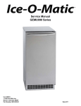
1
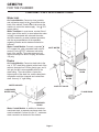
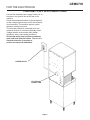
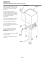
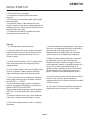
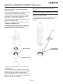
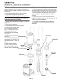
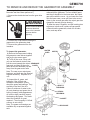
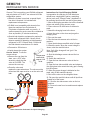
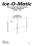
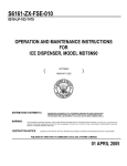
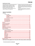
Installation and Service Manual GEMD790 Ice-O-Matic 11100 East 45th Ave Denver, Colorado 80239 P tN Part Number b 9081424-01 9081424 01 Date D t 2/11 Ice-O-Matic Parts and Labor Domestic & International Limited Warranty Mile High Equipment LLC (the “Company”) warrants Ice-O-Matic brand ice machines, ice dispensers, remote condensers, water filters, and ice storage bins to the end customer against defects in material and factory workmanship for the following: Cube ice machines,”GEM” model compressed ice machines , “MFI” model flake ice machines and remote condensers. Thirty-six (36) months parts and labor “EF” model flake ice machines and GEMD maker dispensersTwenty-four (24) months parts and labor CD model dispensers - Thirty-six (36) months parts and labor Ice storage bins -Twenty-four (24) month parts and labor IOD model dispensers - Twenty-four (24) months parts, Twelve (12) months labor Water filter systems - Twelve (12) months parts and labor (not including filter cartridges) An additional twenty-four (24) month warranty on parts (excluding labor) will be extended to all cube ice machine evaporator plates and compressors, “GEM” model compressed ice machine compressors, and “MFI” model flake ice machine compressors from the date of original installation. An additional thirty-six (36) month warranty on parts (excluding labor) will be extended to all “EF” model flake ice machine and “GEMD” maker dispenser compressors from the date of original installation. The company will replace EXW (Incoterms 2000) the Company plant or, EXW (Incoterms 2000) the Companyauthorized distributor, without cost to the Customer, that part of any such machine that becomes defective. In the event that the Warranty Registration Card indicating the installation date has not been returned to Ice-O-Matic, the warranty period will begin on the date of shipment from the Company. Irrespective of the actual installation date, the product will be warranted for a maximum of seventy-two (72) months from date of shipment from the Company. ICE-model cube ice machines which are registered in the Water Filter Extended Warranty Program will receive a total of eighty-four (84) months parts and labor coverage on the evaporator plate from the date of original installation. Water filters must be installed at the time of installation and registered with the Company at that time. Water filter cartridges must be changed every six (6) months and that change reported to the Company to maintain the extended evaporator warranty. No replacement will be made for any part or assembly which (I) has been subject to an alteration or accident; (II) was used in any way which, in the Company’s opinion, adversely affects the machine’s performance; (III) is from a machine on which the serial number has been altered or removed; or, (IV) uses any replacement part not authorized by the Company. This warranty does not apply to destruction or damage caused by unauthorized service, using other than Ice-O-Matic authorized replacements, risks of transportation, damage resulting from adverse environmental or water conditions, accidents, misuse, abuse, improper drainage, interruption in the electrical or water supply, charges related to the replacement of non-defective parts or components, damage by fire, flood, or acts of God. This warranty is valid only when installation, service, and preventive maintenance are performed by a Company-authorized distributor, a Companyauthorized service agency, or a Company Regional Manager. The Company reserves the right to refuse claims made for ice machines or bins used in more than one location. This Limited Warranty does not cover ice bills, normal maintenance, after-install adjustments, and cleaning. Limitation of Warranty This warranty is valid only for products produced and shipped from the Company after March 2011. A product produced or installed before that date shall be covered by the Limited Warranty in effect at the date of its shipment. The liability of the Company for breach of this warranty shall, in any case, be limited to the cost of a new part to replace any part, which proves to be defective. The Company makes no representations or warranties of any character as to accessories or auxiliary equipment not manufactured by the Company. REPAIR OR REPLACEMENT AS PROVIDED UNDER THIS WARRANTY IS THE EXCLUSIVE REMEDY OF THE CUSTOMER. MILE HIGH EQUIPMENT SHALL NOT BE LIABLE FOR ANY INCIDENTAL OR CONSEQUENTIAL DAMAGES FOR BREACH OF ANY EXPRESS OR IMPLIED WARRANTY ON THIS PRODUCT. EXCEPT TO THE EXTENT PROHIBITED BY APPLICABLE LAW, ANY IMPLIED WARRANTY OR MERCHANTABILITY OR FITNESS FOR A PARTICULAR PURPOSE ON THIS PRODUCT IS LIMITED IN DURATION TO THE LENGTH OF THIS WARRANTY. Filing a Claim All claims for reimbursement must be received at the factory within 90 days from date of service to be eligible for credit. All claims outside this time period will be void. The model, the serial number and, if necessary, proof of installation, must be included in the claim. Claims for labor to replace defective parts must be included with the part claim to receive consideration. Payment on claims for labor will be limited to the published labor time allowance hours in effect at the time of repair. The Company may elect to require the return of components to validate a claim. Any defective part returned must be shipped to the Company or the Company-authorized distributor, transportation charges pre-paid, and properly sealed and tagged. The Company does not assume any responsibility for any expenses incurred in the field incidental to the repair of equipment covered by this warranty. The decision of the Company with respect to repair or replacement of a part shall be final. No person is authorized to give any other warranties or to assume any other liability on the Company’s behalf unless done in writing by an officer of the Company. GOVERNING LAW This Limited Warranty shall be governed by the laws of the state of Delaware, U.S.A., excluding their conflicts of law principles. The United Nations Convention on Contracts for the International Sale of Goods is hereby excluded in its entirety from application to this Limited Warranty. Mile High Equipment LLC, 11100 East 45th Avenue, Denver, Colorado 80239 (303) 371-3737 March 2011 Ice‐O‐Matic is devoted to sustainability in every aspect of our business. So to help offset our carbon footprint, we work with American Forests to plant a tree for every ice machine we sell. Our ultimate goal is to plant 150,000 trees over the next several years. GEMD790 INTRODUCTION To the owner or user: The service manual you are reading is intended to provide you, and the maintenance or service technician with the information needed to install, start up, clean, maintain, and service this ice maker-dispenser. The GEMD790 is a combination GEM ice maker and countertop dispenser. A water station is standard. The ice making section is equipped with the following features: electronic controls for bin level and low water; thermostatic expansion valve; front service for most components; and R-404A refrigerant. The ice dispensing section is a seamless plastic storage bin, with a stainless steel ice agitator at the bottom to sweep the ice into the dispensing chute. Table of Contents FOR THE INSTALLER: Specifications · · · · · · · · · · · · · FOR THE INSTALLER · · · · · · · · · · · · · · · · · · · · · FOR THE PLUMBER · · · · · · · · · · · · · · · · · · · · · · FOR THE ELECTRICIAN · · · · · · · · · · · · · · · · · · · · FOR THE INSTALLER: Final Check List · · · · · · · · · · · · INITIAL START UP · · · · · · · · · · · · · · · · · · · · · · · COMPONENT DESCRIPTION · · · · · · · · · · · · · · · · · COMPONENT DESCRIPTION · · · · · · · · · · · · · · · · · CONTROL BOX · · · · · · · · · · · · · · · · · · · · · · · · ELECTRICAL SEQUENCE · · · · · · · · · · · · · · · · · · · OPERATION: Water · · · · · · · · · · · · · · · · · · · · · · OPERATION: Refrigeration · · · · · · · · · · · · · · · · · · OPERATION: Ice Vending · · · · · · · · · · · · · · · · · · · DISPENSE AREA SANITATION · · · · · · · · · · · · · · · · CLEANING and SANITIZING · · · · · · · · · · · · · · · · · · SENSOR MAINTENANCE · · · · · · · · · · · · · · · · · · · BEARING MAINTENANCE · · · · · · · · · · · · · · · · · · · AUGER MAINTENANCE · · · · · · · · · · · · · · · · · · · · SERVICE DIAGNOSIS · · · · · · · · · · · · · · · · · · · · · CONTROL SYSTEM DIAGNOSTICS · · · · · · · · · · · · · REMOVAL AND REPLACEMENT · · · · · · · · · · · · · · · REMOVAL AND REPLACEMENT: Bearing And Breaker · · · REMOVAL AND REPLACEMENT · · · · · · · · · · · · · · · REMOVAL AND REPLACEMENT: Water Seal · · · · · · · · REMOVAL AND REPLACEMENT · · · · · · · · · · · · · · · TO REMOVE AND REPAIR THE GEARMOTOR ASSEMBLY · REFRIGERATION SERVICE · · · · · · · · · · · · · · · · · · WIRING DIAGRAMS · · · · · · · · · · · · · · · · · · · · · · · · · · · · · · · · · · · · · · · · · · · · · · · · · · · · · · · · · · · · · · · · · · · · · · · · · · · · · · · · · · · · · · · · · · · · · · · · · · · · · · · · · · · · · · · · · · · · · · · · · · · · · · · · · · · · · · · · · · · · · · · · · · · · · · · · · · · · · · · · · · · · · · · · · · · · · · · · · · · · · · · · · · · · · · · · · · · · · · · · · · · · · · · · · · · · · · · · · · · · · · · · · · · · · · · · · · · · · · · · · · · · · · · · · · · · · · · · · · · · · · · · · · · · · · · · · · · · · · · · · · · · · · · · · · · · · · · · · · · · · · · · · · · · · · · · · · · · · · · · · · · · · · · · · · · · · · · · · · · · · · · · · · · · · · · · · · · · · · · · · · · · · · · · · · · · · · · · · · · · · · · · · · · · · · · · · · · · · · · · · · · · · · · · · · · · · · · · · · · · · · · · · · · · · · · · · · · · · · · · · · · · · · · · · · · · · · · · · · · · · · · · · · · · · · · · · · · · · · · · · · · · · · · · · · · · · · · · · · Page 2 Page 3 Page 4 Page 5 Page 6 Page 7 Page 8 Page 9 Page 10 Page 11 Page 12 Page 13 Page 14 Page 15 Page 16 Page 17 Page 18 Page 19 Page 20 Page 21 Page 22 Page 23 Page 24 Page 25 Page 26 Page 27 Page 28 Page 29 Note this symbol when it appears. This manual was printed on recycled paper. Keep it for future reference. It marks a possible hazard. Page 1 GEMD790 FOR THE INSTALLER: Specifications This ice maker-dispenser is designed to be mounted on a machine stand, or a countertop. Before beginning the installation, check that all the materials and kits required are available at the installation location. Ice-O-Matic ice machines are designed and manufactured with the highest regard for safety and performance. They meet or exceed the standards of U.L., N.S.F., and C.U. L. Ice-O-Matic assumes no liability or responsibility of any kind for products manufactured by Ice-O-Matic that have been altered in any way, including the use of any parts and/or other components not specifically approved by Ice-O-Matic. Ice-O-matic reserves the right to make design changes and/or improvements at any time. Specifications and designs are subject to change without notice. BACK VIEW Water Limitations: An ice machine is a food manufacturing plant; it takes in a raw material, water, and turns it into a food product, ice. The purity of the water is very important in obtaining pure ice and in maximizing product life. General recommendations Electrical Junction are: Box 1. Filter the water used to produce ice. 3/8" Flare Water Inlet 2. Check with a water treatment specialist for a water test, and any 6.63" recommendations regarding 12.5" filters and treatment. 3/8" FPT Cond. Water Inlet (W/C) 1/2" FPT Cond. Drain (W/C) 3/4 FPT Drain 4.63" 3.84" .75" 2.63" 3/4" FPT Drain Model Number GEMD790 7.93" 5.59" 17.59" Basic Minimum Max. Condenser Refrigerant Dimensions Fuse Electrical Circuit Type Charge (w/o stand) Ampacity* Size (R-404A) H" x W" x D" 45.80 x 35.20 x 27.31 Air 32 115/60/1 18.1 25 *Minimum circuit ampacity is used to determine wire size and type per National Electric Code. Options: Machine stand GEMD5 or GEMD7. Page 2 GEMD790 FOR THE INSTALLER Location This ice system is designed to be installed indoors, in a controlled environment. Minimum Maximum 1000F. Air Temp 500F. 1000F. Water Temp 400F. Water Pressure 20 psi 80 psi Voltage 104 126 Operating the machine outside of the above limitations, or outdoors, is potentially damaging to the machine; also it is misuse of the machine which may void the warranty. Service Limitations Do not install in a location where the top of the machine is within 6" of a fixed ceiling. Air cooled models require a minimum of 6 inches to the left and right of the machine for air circulation. It is important that the machine be installed in a location where it has enough space above and behind it for service. After uncrating and inspection, the unit is ready for installation. Machine Stand Installation Tip the stand on its back and install the legs, return the stand to the upright position. Adjust leg levelers so that the stand does not “rock”. Counter Top or Machine Stand Installation The base of the icemaker-dispenser must be sealed to the object it rests upon. Food grade silastic sealant is recommended. Place a bead of the sealant on the machine stand or counter top to match the outside edge of the cabinet base and sink. The icemaker-dispenser is heavy: use of a mechanical hoist is recommended to lift it to the height required to install it. The DMS machine stand has holes in the top that match up with threaded holes in the base of the machine. Secure the machine stand to the base with 4 5/16" bolts. In both counter top and machine stand installations, wipe off and neatly smooth any excess sealant. Level the machine stand and cabinet. Unpack and install the sink brackets. Fit the sink assembly onto the two sink brackets, and press onto the bead of sealant. Wipe off and neatly smooth any excess sealant from under the sink edge. Connect the sink drain to the dispenser drain system. SEAL ICEMAKERDISPENSER TO THE COUNTER TOP OR MACHINE STAND Page 3 Airflow GEMD790 FOR THE PLUMBER CONFORM TO ALL APPLICABLE CODES Water Inlet Air Cooled Models: Connect a clean, potable and cold water supply to the 3 8” male flare at the back of the cabinet. Install a hand valve near the machine to control the water supply. Use 3 8” O.D. copper tubing. Water Treatment: In most areas, a water filter of some type will be useful. In areas where the water is highly concentrated with minerals the water should be tested by a water treatment specialist, and the recommendations of the specialist regarding filtration and/or treatment should be followed. Water Cooled Models: Connect a separate 3 8” INLET WATER O.D. copper line, with a separate hand valve to control it, to the 3 8” FPT condenser inlet at the back of the cabinet. The water pressure to all lines must always be above 20 psig, and below 120 psig. Drains Air Cooled Models: Connect a drain tube to the one ¾” FPT drain fitting (plastic) at the back of the cabinet, the drain line is of the gravity type, and ¼ inch per foot fall is an acceptable pitch for the drain tubing. There should be a vent at the highest point of the drain line, and the ideal drain receptacle would be a trapped and vented floor drain. Use only ¾” rigid tubing. VENTED DRAIN OPTIONAL WATER FILTER WATER COOLED SHUT OFF VALVE CONDENSER WATER INLET FLOOR DRAIN CONDENSER DRAIN Water Cooled Models: In addition to the above mentioned drain, a separate condenser drain line must be installed. Connect it to the ½ " condenser drain connection at the back of the cabinet. Page 4 GEMD790 FOR THE ELECTRICIAN CONFORM TO ALL APPLICABLE CODES Connect the electrical power supply for the unit to the wires in the junction box at the rear of the machine. Check the nameplate (located on the back panel) for the voltage requirements, and for the minimum circuit ampacity. The machine requires a solid chassis to earth ground wire. The ice maker should be connected to its own electrical circuit so it would be individually fused. Voltage variation must remain within design limitations, even under starting conditions. All external wiring must conform to national, state, and local electrical codes. The use of a licensed electrician is required to perform the electrical installation. POWER SUPPLY ELECTRICAL CONNECTION Page 5 GEMD790 FOR THE INSTALLER: Final Check List 1. Is the icemaker-dispenser installed indoors, in a location where the air and water temperatures are controlled, and where they do not go beyond design limitations? ELECTRICAL? 2. is there an electrical service disconnect within sight of the installed machine? Is the machine on a separate circuit? Has the voltage been checked and compared to nameplate requirements? 3. Have all of the plumbing connections been made and checked for leaks? 4. Has the machine been leveled? 5. Is there a minimum of 6 inches of clearance at the left and right sides of an air cooled machine? 6. Is there a minimum of 6 inches of clearance at the top and back of the machine for service and utility connections? 7. Is there a water shut off valve installed near the machine? WATER INLET? 8. Have all of the shipping blocks been removed? DRAINS? Page 6 LEVELED? GEMD790 INITIAL START UP Pre Start Inspection 1. Remove the two front panels. 2. Check that all shipping blocks have been removed. 3. Remove any and all packing tape (check inside the storage bin). 4. Inspect the interior of the machine for loose screws or wires. Check that no refrigerant lines are rubbing each other. Check that the fan blade on air cooled models turns freely. 5. Check that the machine is installed correctly according to the final check list. Start Up 1. Go through the pre start inspection. 7. Check ice dispensing by pushing in on the glass filler lever. Ice dispenses are portion controlled; by turning a knob, the length of time the unit dispenses when the glass filler lever is pushed (and the amount of ice dispensed) is adjusted. 2. Open the water hand valve, observe that water enters the water reservoir, fills the tube from the reservoir to the evaporator and then shuts off. Check for leaks. 3. Switch the mode switch to ON. The auger drive motor and compressor start, beginning the ice making process. 4. On air cooled models, warm air will begin to flow from the condenser. Water cooled models will begin to discharge warm water down the drain. 5. The unit should soon be making ice. If desired, the low side pressure may be checked: it should be 38 PSIG + or - 4 PSIG. The air cooled discharge pressure will depend upon air and water temperatures, but should be between 200 PSIG and 300 PSIG. Water cooled discharge pressure should be about 245 PSIG. If needed, adjust the water regulating valve. The above numbers are for new, clean machines. Field values may be somewhat higher or lower. 8. Switch off the icemaker-dispenser, remove the top panel and the top of the ice storage bin. Sanitize the interior of the ice storage bin with a locally approved sanitizer. A possible sanitizer is a mixture of 1 ounce of household bleach to 2 gallons of water. Wash the interior of the bin with the sanitizing solution. Replace all covers and panels. Switch the icemaker-dispenser back on. 9. Give the owner/user the service manual, instruct him/her in the operation and maintenance requirements of the unit. Make sure they know who to call for service. 10. Fill out the Customer Evaluation and warranty Registration form, and mail it in to Ice-O-Matic. 6. There are no adjustments to make, so replace the panels. Page 7 GEMD790 COMPONENT DESCRIPTION RESERVOIR WATER LEVEL SENSOR ICE LEVEL SENSOR ICE STORAGE BIN CONTROL BOX EVAPORATOR DRAIN TUBE CONDENSER HI PRESSURE Ice Level Sensor: An electronic “eye”, it senses the presence of ice in the bottom of the ice CUT OUT discharge chute. Operates to turn the ice machine on and off automatically as the level of ice in the bin changes. Control Box: Contains the electrical controls that operate the machine. High Pressure Cut Out Switch: An automatic reset switch sensing the high side refrigeration pressure. It is set to shut the machine off if the discharge pressure should ever exceed 450 psig. Evaporator: A vertical stainless steel tube, refrigerated, and water filled. In it there is a stainless steel auger. Reservoir: Float operated, it maintains the water level in the evaporator at a constant level, it also contains the water level sensor. Water Level Sensor: Senses if there is water in the reservoir to make ice out of. Will shut the machine off it there is none. Drain Tube: When uncapped and lowered, drains the evaporator. Condenser: Air or water cooled, where the heat removed in ice making is discharged. Ice Storage Bin Assembly: A plastic lined, insulated cylinder that receives, stores and dispenses the ice. Fresh ice enters at the top, and when the bin is full enough the ice will be between the ice level sensors, and the icemaking will stop. Ice is dispensed through a chute at the bottom front when the agitator assembly sweeps the ice through the chute. Page 8 GEMD790 COMPONENT DESCRIPTION Evaporator: A refrigerated vertical tube filled with water and containing a water seal and auger. Auger: A solid stainless steel double spiral auger, it pushes the ice crystals up to the top of the evaporator. Water Seal: A two part “face” seal, the top half rotating with the auger, the bottom half stationary, the sealing action being where the two seal “faces” meet. Ice Sweep: A plastic cap with “fingers”. It revolves with the auger to “sweep” the ice into the ice chute. Breaker: Where the ice is compressed and much of the extra water is squeezed out of it before it is discharged into the bin. Motor: A split phase motor that drives the gear reducer. Thrust Bearing: As the ice is pushed up the evaporator, the auger is thrust down, and pressure from the auger thrust is taken up by this bearing. ICE SWEEP BEARING BREAKER ICE CHUTE EVAPORATOR AUGER WATER SEAL WATER INLET GEAR MOTOR Page 9 GEMD790 CONTROL BOX Circuit Board: The circuit board receives input signals from several sensors and translates them to control the electrical power supply to the various loads. The sensors include: · Touch Free ice or water. · Ice level in the bin. · Water level in the reservoir. The loads include: · Compressor contactor · Fan motor · Bin drive motor · Auger drive motor · Water solenoid. In addition, a “Clean” switch is available to temporarily disable the Touch-Free sensors for cleaning of the splash panel. On/Off Switch: Manual control for the machine. Contactor: A definite purpose contactor connecting the compressor to the power supply. Potential Relay: The compressor start relay. Touch Free Control Board Page 10 GEMD790 ELECTRICAL SEQUENCE Refer the wiring diagram as needed. The “Power” light on the board glows whenever there is power to the machine (and the master switch is ON). If the machine is switched off at the master switch, but is otherwise ready to go, switching the master switch to ON does the following: · The bin empty and power lights on the circuit After a 6 minute delay, If the ice level sensor is clear (bin empty) for more than 15 seconds, the machine will start up again. Another purpose of the circuit board is to turn the machine off if there is not enough water in the machine. · When the water level in the reservoir falls below the tip of the water level sensor, the machine will “shut down” board glow. · After a 6 minute delay, if the water refills the · There is a 15 second delay · If there is enough water in the reservoir, the reservoir, the machine will start up again. Separate from the circuit board: circuit board will allow the machine to start up. Start up consists of: · If the high pressure control (cut out switch) opens, the compressor will stop immediately (through the contactor). It will automatically reset when the discharge pressure drops below 350 PSIG. · The compressor contactor coil receives power from the circuit board. · The contactor is energized, connecting power to the compressor, and the compressor starts. · The auger motor receives power from the circuit board and starts. · As ice goes past the ice level sensors, the bin empty light will stay on and the machine will continue to run, unless the ice stays between the sensors for more than 15 seconds (bin full). At that point, the bin empty light goes out, and the machine shuts down. Other reasons for shut down: · The master switch is the manual control for the complete machine, but it is not a service disconnect. Ice Vending · When a user places a container in front of the · Low water level (as sensed by the thermistor in the reservoir). Shut Down consists of: · The compressor contactor opens · The compressor stops · The auger motor is run by the circuit board for 2 more minutes, clearing out ice in the evaporator, and then · The auger motor no longer receives power from the circuit board, and the auger motor stops. Page 11 Touch Free ice sensor and below the ice delivery chute, the circuit board connects power to the bin drive motor and ice is dispensed for as long as the container is present. If the user does not remove the container, ice will be dispensed for 60 seconds and then stop. GEMD790 OPERATION: Water Water enters the machine through the 3/8" male flare at the rear of the cabinet, goes to the water reservoir which it enters through the float valve. The water then goes out the bottom of the reservoir tank to the bottom of the evaporator. Reservoir overflow, evaporator condensation and water in the sink are all routed to the drain. Water cooled models have a separate water circuit for the cooling water: it enters the fitting at the rear, goes to the water regulating valve, then to the water cooled condenser and down the drain. The water dispensing station adds an additional water circuit. When the water station sensor detects a container in front of it, the control board closes a circuit to an electric water valve and water is dispensed. Note: The correct water level is determined when the machine is operating. Check the water level and compare it to the line molded into the side of the reservoir. The water level should be between 1 " above and 1 " below the line. 8 4 If needed, adjust the water level by bending the float arm. WATER LEVEL RESERVOIR RESERVOIR OVERFLOW DRAIN WATER INLET BIN DRAIN WATER VALVE SINK DRAIN WATER SCHEMATIC Page 12 GEMD790 OPERATION: Refrigeration Beginning at the compressor, the refrigerant is compressed into a high temperature gas. The discharge line directs this gas to the condenser. At the condenser (air or water cooled) the gas is cooled by either air or water and it then condenses into a liquid. This high pressure liquid then goes through the liquid line to the expansion valve. The thermostatic expansion valve meters liquid refrigerant into the evaporator, the volume of liquid refrigerant depending upon the temperature of the evaporator; warmer evaporators get more refrigerant and colder evaporators get less. At the evaporator, the refrigerant enters an area of relatively low pressure, where it can easily “boil off” or evaporate. As it evaporates, it absorbs heat from the evaporator and whatever is in contact with it (such as the water inside it). After the evaporator, the refrigerant, now a low pressure vapor, goes through the suction line back to compressor, where the cycle is repeated. REFRIGERATION SCHEMATIC (AIR COOLED SHOWN) SUCTION LINE THERMOSTATIC EXPANSION VALVE LIQUID LINE DISCHARGE LINE EVAPORATOR FAN MOTOR CONDENSER COMPRESSOR Page 13 GEMD790 OPERATION: Ice Vending When the ice dispensing sensor detects a container in front of it, the control board connects an electrical circuit to the ice chute door solenoid causing the ice chute door to open. At the same time power is connected to the agitator drive motor. Dispensing takes place when the agitator sweeps the ice through the ice dispensing chute: ice will continue to discharge out this chute as long as the agitator is turning. It stops when the agitator stops. ICE DISCHARGE CHUTE DOOR SOLENOID ICE CHUTE DOOR STORAGE BIN ICE CHUTE AGITATOR AGITATOR DRIVE MOTOR TOUCH FREE SENSOR SINK Page 14 GEMD790 DISPENSE AREA SANITATION The dispense area; spouts, sink, grill and splash panel will need periodic cleaning and maintenance. 1. The ice chute may be pulled down to remove it from the ice dispenser. Wash and sanitize it. 2. The sink grill may be removed for washing and sanitizing. 3. The sink should be flushed with hot water and wiped clean with sanitizer. 4. The splash panel requires special attention to clean it. · Push and release the Splash Panel Cleaning switch located to the left of the water spout. This disables the Touch Free sensors so the splash panel may be cleaned without vending ice and/or water. · Wash the splash panel and wipe with with sanitizer. Re-push the clean switch or allow 2 minutes to pass for the Touch Free system to reset. Page 15 GEMD790 CLEANING and SANITIZING It is the USER’S RESPONSIBILITY to see that the unit is properly maintained. It is always preferable, and less costly in the long run, to avoid possible down time by keeping it clean; adjusting it as needed; and by replacing worn parts before they can cause failure. The following is a list of recommended maintenance that will help keep the machine running with a minimum of problems. Cleaning should be scheduled at a minimum of twice per year. Sanitizing of the ice storage bin should be scheduled for a minimum of 4 times a year. Electrical power will be ON when doing in place cleaning. ICEMAKING SYSTEM: In place cleaning 1. Check and clean any water treatment devices, if any are installed. 2. Remove screws and remove the upper front panel. 3. Move the ON-OFF switch to OFF. 4. Remove the cover to the ice storage bin, and remove the ice. 5. Remove the cover to the water reservoir and block the float up. 6. Drain the water reservoir and freezer assembly using the drain tube attached to the freezer water inlet. Return the drain tube to its normal upright position and replace the end cap. 7. Prepare the cleaning solution: Mix eight ounces of Ice Machine Cleaner with three quarts of hot water. The water should be between 90-115 Ice Machine Cleaner contains acids. These compounds may cause burns. If swallowed, DO NOT induce vomiting. Give large amounts of water or milk. Call Physician immediately. In case of external contact, flush with water. Keep out of the reach of children. 10. After all of the cleaning solution has been added to the reservoir, and the reservoir is nearly empty, switch the master switch to OFF. 11. After draining the reservoir, as in step 6, wash and rinse the water reservoir. To Sanitize: Repeat steps 8-11, except substitute sanitizer solution for the cleaning solution. A possible sanitizer solution may be made by mixing 1 ounce of household bleach and 2 gallons of warm (95oF. - 115oF.) potable water. 12. Remove the block from the float in the water reservoir. 13. Switch the master switch to ON 14. Continue ice making for at least 15 minutes, to flush out any cleaning solution. Check ice for acid taste - continue icemaking until ice tastes sweet. DO NOT USE any ice produced from the cleaning solution. Be sure no ice remains in the bin. 15. Remove all ice from the storage bin. 16. Add warm water to the ice storage bin and thoroughly wash and rinse all surfaces within the bin. 17. Sanitize the bin interior, cover, door and agitator with an approved sanitizer using the directions for that sanitizer. 18. Replace the ice storage bin cover, and the front panel. degrees F. 8. Slowly pour the cleaning solution into the water reservoir until it is full. Wait 15 minutes, then switch the master switch to ON. 9. As the ice maker begins to use water from the reservoir, continue to add more cleaning solution to maintain a full reservoir. Page 16 GEMD790 SENSOR MAINTENANCE 1. The ice machine senses water level by a probe located in the water reservoir. At least twice a year, the probe should be removed from the reservoir, and the tip wiped clean of mineral build-up. 2. The bin control uses devices that sense light, therefore they must be kept clean enough so that they can “see”. At least twice a year, remove the bin control sensors from the ice chute, and wipe them clean. SLIDE SENSORS UP TO REMOVE Clean the Probe's Tip with ice machine cleaner and a clean, soft cloth. Page 17 GEMD790 BEARING MAINTENANCE The bearing in the breaker should also be checked at least two times per year. A. Check the bearing by: · unscrewing the breaker cover. · removing the ice chute cover Auger Stud Ice Sweep Cap Screw · unscrewing the auger stud · unscrewing the ice sweep · removing the water shed Breaker Cover Inspect the bearing. There should be plenty of grease in sight. If grease is needed the bearing and breaker should be removed to check the action of the bearing. It should rotate smoothly. To remove the breaker remove the lower ice chute then take out all four allen head cap screws and pull the breaker off the auger and evaporator. If the bearing only needs grease, inject grease into the bearing using Ice-O-Matic grease needle pn 1011380-230 and Ice-O-Matic bearing grease , pn 6051062-01. Be sure to inject grease evenly and thoroughly. See Removal and Replacement section to replace bearing or seals. Off Bearing Reverse to reassemble. Page 18 Needle, pn 1011380-230 GEMD790 AUGER MAINTENANCE In some areas, the water supply to the ice maker will contain a high concentration of minerals, and that will result in an evaporator and auger becoming coated with these minerals, requiring a more frequent removal than twice per year. If in doubt about the condition of the evaporator and auger, the auger can be removed so the parts can be inspected. Note: Water filters can filter out suspended solids, but not dissolved solids. “Soft” water may not be the complete answer. Check with a water treatment specialist regarding water treatment. For more information on removal of these parts, see REMOVAL AND REPLACEMENT. Moving Parts Hazard. Disconnect electrical power to the icemaker dispenser before beginning. Disconnect electrical power, and shut off the water supply. Use care when removing the auger, it has sharp edges. 1. To remove the auger, remove the front and top panels. 2. Drain evaporator using drain hose. 3. Remove bail clamp from over ice chute cover and remove cover. 4. Unscrew and remove ice sweep. 5. Remove ice chute from evaporator. 6. Remove 4 allen screws holding breaker to evaporator. 7. Pull up to remove auger. After the auger has been removed, allow the auger to dry: if the auger is not bright and shiny, it must be cleaned. Clean the auger and evaporator as required. DO NOT HONE THE EVAPORATOR. 8. Replace the water seal. 9. Reverse to reassemble. Page 19 BREAKER AND AUGER ASSEMBLY GEMD790 SERVICE DIAGNOSIS Symptom No ice is made, nothing operates No ice, auger motor is turning Unit makes ice, but very slowly. Possible Cause Unit off due to no power Unit off due to master switch in OFF position. Unit off due to low water level. Probable Correction Restore Power Switch master switch to ON. Check water supply, filter, float valve. Correct water supply. Check/clean ice level sensors. Unit off due to ice level sensors (photo-electric eyes) blocked. Unit off due to scale on water level Clean water level sensor. sensor. Unit off due to high pressure Check for water interruption (water control open. cooled) or fan motor failure (air cooled). Auger motor hums but does not Auger can’t turn. turn. No power to circuit board. Check harness HI pressure cut out open Circuit Board gear motor relay will Check, replace board not close Water level or ice level sensor Check, replace sensor failed. Compressor contactor coil is open Check/replace contactor Compressor will not start Check start capacitor. Check start relay Check compressor windings Circuit board compressor relay will Check, replace board not close. High discharge pressure because Clean the condenser. of a dirty condenser Clean the water system Low capacity because the auger and evaporator are coated with mineral scale Low suction pressure due to low Locate leak. Recover refrigerant, refrigerant charge repair leak, replace dryer, evacuate and weigh in the nameplate charge Page 20 GEMD790 CONTROL SYSTEM DIAGNOSTICS The control system consists of: · Control Board · Water Sensor · Ice Sensors · Vending Sensors 1, Power Light 2, Bin Empty Light 3, Delay Timer Light 4, No Water Light Explanation of Indicator Light On at all times when the master switch is ON and machine is connected to electrical power. On when ice level is low (unit making ice). Normal 6 minute off/delay start. To prevent short cycling, the machine will not restart after any shut off (except power to the board) until 6 minutes have passed. On when water level is low in the reservoir. Page 21 Position On Board 1 2 3 4 Name and Meaning of Light or Reset Power, ON = Normal Bin Empty, ON = Needs Ice Off Timer, ON = Unit cycling off No Water, ON = Trouble GEMD790 REMOVAL AND REPLACEMENT WATER RESERVOIR 1. Shut off the water supply to the icemaker. 2. Remove front panel and reservoir cover. 3. To remove float only, pry the mounting flanges apart enough to lift one float pivot pin out of the flange hole, and pull float up and out of the reservoir. 4. To remove reservoir, disconnect water inlet compression fitting at reservoir inlet. 5. Remove drain hose from reservoir. 6. Remove evaporator inlet hose from reservoir. 7. Remove water level sensor probe. 8. Remove mounting screws from reservoir bracket, and remove reservoir from icemaker. 9. Reverse to reassemble. FLOAT ASSEMBLY Water Sensor LOCKING TABS BIN CONTROLS (Ice Level Sensors) 1. Disconnect electrical power. 2. Remove front panel. 3. Remove control box cover. 4. Locate bin top, in front of and behind it are two rubber bin control grommets. 5. Pull each bin control out, and in the control box, disconnect the electrical leads connecting the bin control to the circuit board. 6. Reverse to reassemble, be certain that the bin controls are aligned so that the ice level sensors are visible (centered) through the holes in the ice chute. Page 22 GEMD790 REMOVAL AND REPLACEMENT: Bearing And Breaker Note: Removal of the auger, water seal, evaporator and gearmotor must begin at the top of the assembly. To Remove the Breaker Bearing Assembly: Moving Parts Hazard. Disconnect electrical power to the icemaker dispenser before beginning. 1. Remove panels and disconnect electrical power. 2. Unscrew three studs and remove ice chute cover. 3. Unscrew and remove ice sweep. 4. Lift up and remove ice chute. 5. The breaker may be removed from the auger and evaporator without disturbing the auger. a. Unscrew breaker cover from breaker (left hand threads) b. Unscrew auger stud from top of auger. c. Unscrew 4 allen head cap screws holding breaker to evaporator. ICE SWEEP STEP 5-A d. Lift up, and remove breaker/bearing assembly from auger & evaporator. 6. Service the bearing. Check for rust, rough spots and damage. a. The bearing is pressed into the breaker, to remove the bearing and replace it an arbor press is needed. b. Replace lower seals before installing new bearing in breaker. Note: seals must be pressed in with a tool pushing against the outer edge only, they will not install by hand. Replace parts as required. Re-grease bearing with Ice-O-Matic part no. 6051062-01 bearing grease. Replace top seal, and check the o-rings, replace if cut or torn. 7. Reverse to reassemble: specific tools and materials are required to install properly. a. Add food grade grease such as Ice-O-Matic part number 6051036-01 to the seal area before installing on the auger. b. Check the seal to shaft areas for cuts, or rough spots: none are permitted. STEP 5-B STEPS 5-C AND 6 BREAKER Page 23 BEARING GEMD790 REMOVAL AND REPLACEMENT To Remove the Auger: Turn off the water to the machine, and unclip the evaporator drain hose, pull it down and drain the evaporator into the bin or a container. e. If the auger is stuck use a slide hammer type puller to pull on the auger at the threaded hole. The size of that hole is 5/8"-18. Inspect the auger, the critical areas of the auger are: 1. The auger body. It should be clean and shining. Sometimes an auger will appear clean when wet, but after it is dry it will be seen to be stained. Scrub the auger with ice machine cleaner and hot water. Moving Parts Hazard. Disconnect electrical power to the icemaker dispenser before beginning. Ice machine cleaner is an acid. Handle it with extreme care, keep out of the reach of children. 2. The water seal area. Because the auger has been removed, the water seal will have to be replaced. Remove the water seal top half from the auger, and inspect the auger for minerals clean as required. 1. The top panel must be removed. 2. Remove ice chute cover. 3. Unscrew ice sweep. 4. Remove ice chute body. 5. The auger and breaker/bearing may now be removed as an assembly. BREAKER/ BEARING/ AUGER ASSEMBLY SHARP EDGES! SLIDE HAMMER PULLER THREAD INTO AUGER a. Unscrew 4 allen head cap screws holding breaker to evaporator. b. Lift up on breaker and remove auger from evaporator. Note: If the auger is stuck, the breaker must be removed from the auger. The breaker may be removed from the auger and evaporator without disturbing the auger. a. Unscrew breaker cover from breaker (left hand threads) b. Unscrew auger stud from top of auger. c. Unscrew 4 allen head cap screws holding breaker to evaporator. d. Lift up & remove breaker from evaporator. Page 24 GEMD790 REMOVAL AND REPLACEMENT: Water Seal To Remove the Water Seal: (Assuming all steps to remove the auger have been performed.) 1. The gearmotor/evaporator assembly will have to be exposed. (See illustration - next page) 2. Remove the 4 hex head cap screws holding the evaporator to the gearmotor assembly. Lift the evaporator up and off of the gearmotor. 3. Remove the snap ring or wire retainer from the grove under the water seal. 4. Pull or drive out the lower half of the water seal. To Replace the Water Seal: 1. Lubricate the water seal with water, and push the water seal into the bottom of the evaporator slightly past the grove for the snap ring. 5. Carefully push the water seal (rubber side against the auger shoulder and the silastic sealant.) Do not get any sealant onto the face of the seal. 6. Allow the auger and seal to air dry until the sealant is dry on the surface. 7. If the original water seal was leaking, it would be a good idea to inspect the interior of the gearmotor. WATER SEAL RETAINING RING 2. Replace the snap ring and pull the water seal down against it. 3. The part of the water seal that rotates with the auger must also be replaced. Remove the old part from the auger and clean the mounting area. 4. Place a small bead of food grade silastic sealant (such as 732 RTV ) on the area of the auger where the water seal is to be mounted. Page 25 FOOD GRADE SEALANT HERE GEMD790 REMOVAL AND REPLACEMENT To Replace the Evaporator: (Assuming all the steps for removal of the thrust bearing, breaker, auger, and water seal have been performed.) 1. Recover the refrigerant from the ice maker. 2. Unsweat the refrigerant connections: a) At the thermostatic expansion valve outlet. Heat sink the TXV body when unsweating or resweating the adjacent tubing. b) At the suction line at the joint about 3" from the evaporator. 3. Remove the evaporator. 4. Unsweat the drier from the liquid line. 5. After installing a new water seal in the new evaporator (see “To Replace the Water Seal”) sweat in the new evaporator at the old tubing connections. 6. Install an new drier in the liquid line. EVAPORATOR 7. Evacuate the system until dehydrated, then weigh in the nameplate charge. Check for leaks. 8. Install auger, breaker, breaker bearing assembly, WATER and ice discharge chute in SEAL reverse order of disassembly. To Reassemble the Evaporator and Auger 1. After the gearmotor has been inspected, fasten the evaporator to the gear motor, be sure that the number of shims indicated on the gear case cover is in place between the gearcase cover and the drip pan gasket. Torque the bolts to 110 inch pounds. 2. Lower the auger into the evaporator barrel, slightly turning it to match up with the drive end. Do Not Drop Into the Evaporator. 3. Complete the reassembly by reversing the disassembly for the breaker & thrust bearing assembly. BREAKER ICE SWEEP RETAINING RING BREAKER COVER DRIP PAN BEARING AUGER Page 26 GEMD790 TO REMOVE AND REPAIR THE GEARMOTOR ASSEMBLY (Assuming that the procedures through removal of the water seal have been performed.) 1. Remove the electrical wires from the gear drive motor. Electrical Shock Hazard. Disconnect electrical power to the icemaker dispenser before beginning. D) After replacing parts as required, (if any) reassemble the gearcase. The two smaller gears and the oil should be in the lower case, the output gear will be with the cover. As you lower the cover onto the lower case, cover will have to be moved closer to the second gear after the output gear has cleared the second gear top bearing. E) After the case is together, and the locating pins are secure in both ends, replace all cap screws. 4. Bench test the gearmotor, check for oil leaks, noise, and amp draw. 2. Unscrew the 4 cap screws holding the gearmotor to the gearmotor plate. 3. Remove the gearmotor from the icemaker. To Inspect the gearmotor. A) Remove the cap screws holding the gearmotor case halves together and pry the two cases apart. B) To lift off the cover, lift up until you can feel internal contact, then pull the cover towards the output GEARCASE gear end, and then lift the cover COVER (with drive motor attached) up and away from the gear motor case. Note: The case cover output gear, bearings, and shaft are one pressed together assembly. Replace as a unit. C) Inspect the oil, gears, and bearings. If the oil level and condition is acceptable, quickly check the gears and bearings. They are likely to be fine if the oil is. If there is evidence of water in the oil (rusty bearings and gears; the oil having a creamy white appearance; oil level too high) carefully inspect the bearings and gears. If in doubt about the condition of a part, replace it. The oil quantity is 14 fluid ounces, do not overfill. Note: The gears and bearings are available only as pressed together sets. WATER SHED SWITCH MOTOR BEARING GEAR & BEARINGS GEAR & BEARINGS GASKET GEAR CASE Page 27 GEMD790 REFRIGERATION SERVICE General: This ice machine uses R-404A refrigerant and polyolester oil. Do NOT use mineral oil in this refrigeration system. Instructions for Liquid Charging R-404A In preparation for charging, the low side hose should have a sight glass, and/or a restricting device (such as a “Charge Faster”) installed in it · When the system is serviced, a special liquid for metering liquid into the low side of the system. line drier is required. It is included with 1. After a thorough evacuation shut off the manifold replacement compressors. valves and switch off the vacuum pump. · R-404A is not compatible with mineral oil so 2. Place a drum of R-404A onto an electronic these ice machines use Polyolester oil. scale. Polyolester oil absorbs water very easily. A 3. Attach the charging hose to the drum. system opened for service must be re-sealed as 4. Open the valve on the drum and purge the soon as possible (15 minutes maximum). charging hose. · Special leak detection equipment is required to 5. Zero out the scale. locate small refrigerant leaks. Usually a leak 6. Shut the low side access valve at the ice detector capable of detecting a Halongenated machine. refrigerant or HFC-134a will work. Check with 7. Open the discharge manifold valve full open. the leak detector manufacturer if in doubt. 8. Watch the scale, when the correct charge is · Evacuate to 300 microns. shown, shut the manifold valve. Note: If all of the charge will not “go in” the · Liquid charge the system discharge side: Access Valves: To use the A. Shut the discharge access valve at the ice access valves: Torque stem machine. · Remove the cap from the to 6-8 ft.-lb., B. Switch the machine on. stem, use a 3/16" allen caps to 7-12 C. Open the low side access valve at the ice wrench to check that the ft.-lb. machine. valve is CLOSED. The D. Open the low side manifold valve and observe remove the core cap. the sight glass to be certain that only gas is flowing · Close the valve and into the system. replace the caps when done. The valve must be E. When the proper charge is indicated on the closed and the caps must be on or the valve will scale, shut off the manifold valve(s). leak. 9. Shut off the valve on the refrigerant drum. 10. Re-open the manifold valves until all liquid has flowed out of the hoses. 11. Shut the low side access valve on the ice R-404A machine. Tank Must 12. Remove hoses from ice machine and replace Be in Liquid all caps. Dispensing Sight Glass Position Check Tank! SCALE Hose Connection Schematic for Liquid Charging Page 28 GEMD790 Schematic Diagram Page 29 GEMD790 Wiring Diagram, 115/60/1 Page 30