1
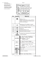
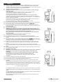
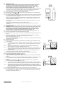
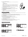
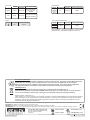
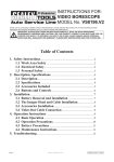
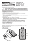
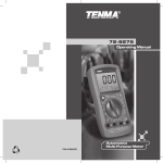
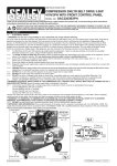
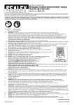
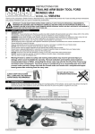
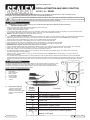
INSTRUCTIONS FOR: DIGITAL AUTOMOTIVE ANALYSER 8 FUNCTION MODEL No: TA200 Thank you for purchasing a Sealey product. Manufactured to a high standard, this product will, if used according to these instructions, and properly maintained, give you years of trouble free performance. IMPORTANT: PLEASE READ THESE INSTRUCTIONS CAREFULLY. NOTE THE SAFE OPERATIONAL REQUIREMENTS, WARNINGS & CAUTIONS. USE THE PRODUCT CORRECTLY AND WITH CARE FOR THE PURPOSE FOR WHICH IT IS INTENDED. FAILURE TO DO SO MAY CAUSE DAMAGE AND/OR PERSONAL INJURY AND WILL INVALIDATE THE WARRANTY. KEEP THESE INSTRUCTIONS SAFE FOR FUTURE USE. 1. SAFETY WARNING! It is the user’s responsibility to read, understand and abide by the following safety instructions. 1.1. PERSONAL PRECAUTIONS When using this meter, please observe all normal safety rules concerning: Protection against the dangers of electric current. Protection of the meter against misuse. Full compliance with safety standards can only be guaranteed if used with the test leads supplied. If necessary, they must be replaced with genuine Sealey leads with the same electronic ratings. Failure to do so will invalidate the warranty. DO NOT use leads if damaged or if the wire is bared in any way. 1.2. GENERAL SAFETY INSTRUCTIONS Familiarise yourself with the applications, limitations and hazards of the meter. IF IN ANY DOUBT CONSULT A QUALIFIED ELECTRICIAN. Before using the meter inspect the case. If you suspect any part of the case to be damaged or missing DO NOT USE THE METER. Remove it from service immediately and contact your local Sealey dealer for advice/repairs. When the meter is linked to a measurement circuit, do not touch unused meter terminals. When the scale of the value to be measured is unknown set the selector to the highest range available. Before rotating the rotary switch to change functions, disconnect test leads from the circuit under test. WARNING! Never perform resistance measurements on live circuits. Always be careful when working with voltages above 60Vdc or 30Vac rms. Keep your fingers behind the probe guards while measuring. When not in use, store the meter carefully in a safe, dry, childproof location. Storage temperature range -10ºC to 50ºC. Never apply voltage or current to the meter that exceeds the specified maximum. Should the low battery indicator appear on the LCD display, replace the battery immediately (PP3). A low battery level could cause the meter to produce inaccurate readings. When not in use, store the meter in a safe, dry, cool and childproof location. DO NOT place in the proximity of a powerful source of electromagnetic radiation. The user shall ensure that test probes are correctly selected in order to prevent danger. Probes shall be selected to ensure that adequate barriers guard against inadvertent hand contact with live conductors under test and that probes have minimal exposed probe tips. Where there is a risk of the probe tip short circuiting with other live conductors under test, it is recommended that the exposed tip length shall not exceed 4mm. 2. INTRODUCTION Durable bi-composite case and integral stand suitable for the toughest workshop conditions. Large, hi-contrast LCD display with 21mm high digital read-out. Unique Test Lead Connection feature indicates correct hook-up. Includes data hold feature and low battery display. Supplied with test probes, crocodile clips and comprehensive manual. Fig.1 3. FEATURES 1. LCD display 2. Data hold button 3. Rotary switch 4. Input terminals 5. Power ON/OFF 6. Crocodile clips 7.Probes 6 7 3.1. Rotary Switch (fig.1(3)) The rotary switch allows selection of the various functions available and of the settings for each individual function. Rotary Switch Position Function DC voltage measurement AC voltage measurement DC Current measurement Diode test Continuity test Resistance measurement Automotive ignition dwell testing (degrees) Automotive engine tach (rotation speed) testing (x10 rpm) © Jack Sealey Limited Original Language Version TA200 Issue No: 4(L) - 16/06/14 3.2. Fig 2 Display (Fig 2) The LCD displays the measured values obtained in tests and various other information regarding the state/operation of the meter. The following is an illustration and descriptive list to enable the user to understand the information presented. Battery is low. Replace immediately using a PP3 9V battery. Failure to do so could lead to inaccurate readings. Indicates an AC voltage or current. The displayed value is the mean value Indicates a negative reading Diode test Continuity buzzer is on Data hold function is active Indicates the requirement for test leads to be connected. Ω: Ohm. The unit of resistance. kΩ: kilohm. 1x10³ or 1000 ohms. MΩ:Megaohm. 1x10⁶ or 1,000,000 ohms. V: Volts. The unit of voltage. mV:Millivolt. 1x10⁻³ or 0.001 volts A: Amperes (amps). The unit of current. mA:Milliamp. 1x10⁻³ or 0.001 amperes Test of Dwell. Tach x 10 Number of cylinders Caution - high voltage testing © Jack Sealey Limited Original Language Version TA200 Issue No: 4(L) - 16/06/14 6. OPERATION Note: During any of the following testing procedures, the data hold function can be employed. When the “HOLD” button (see fig 1.2) is pressed, data hold is activated and the value displayed at that instant on the LCD is held until the HOLD button is pressed again, at which point the LCD once more displays the current measured value. 4.1. AC or DC voltage testing (fig 3) WARNING! To reduce risk of electric shock, DO NOT attempt to measure voltages higher than 1000V. The measurement ranges DC voltage are 200mV, 2V, 20V, 200V and 1000V. The measurement ranges AC voltage are 2V, 20V, 200V and 750V. Select the range appropriate to the expected reading. If the voltage to be measured is unknown, use the maximum measurement position (1000V DC, 750V AC) and reduce the range, step by step until a satisfactory reading is obtained. Should the meter become overloaded, the LCD will display “1”. This indicates that a higher range must be selected. In each range, the meter has an input impedance of approx 10MΩ. This may give rise to measurement errors when dealing with high impedance circuits. If the circuit impedance is <= 10kΩ, the error is negligible (0.1% or less). 4.1.1. To measure DC or AC voltage, connect the meter as follows: 4.1.2.Insert the red test lead into the “V” terminal and the black test lead into the “COM” terminal. 4.1.3.Set the rotary switch to an appropriate measurement position in or 4.1.4.Connect the test leads across the source being measured. The measured value will be displayed. When the measurement has been completed, disconnect the test leads from the circuit being tested. 4.2. DC Current testing (fig 4) WARNING! Never attempt an in-circuit current measurement where the open circuit voltage between terminals and ground is greater than 250V. If the fuse burns out during measurement, the meter may be damaged and the user may be injured. Always use correct terminals, function and range for the measurement. When the test leads are connected to the current terminals, DO NOT parallel them across any circuit. The measurement ranges for DC current are 200.0mA and 10.00A. 4.2.1.To measure DC current, use the following procedure: 4.2.2.Turn off/disconnect power to the circuit, discharge all high voltage capacitors. 4.2.3.Insert the red test lead into the mA or 10A terminal and the black test lead into the COM terminal. 4.2.4.Set the rotary switch to an appropriate measurement position in . If the current to be measured is unknown, use the maximum measurement position (10A) and the 10A terminal, then reduce the range step by step until a satisfactory reading is obtained. 4.2.5.Break the current path to be tested, connect the red test lead to the positive side of the break and the black test lead to the negative side of the break (i.e. connect the meter in series). 4.2.6.Turn on/reconnect power to the circuit. The measured value is shown on the display. When the measurement has been completed, disconnect the test leads from the circuit being tested. Note: Within the 10A range, the meter must not be used for a period of greater than 10 seconds more than once in any 15mins. 4.3. Resistance testing (fig 5) WARNING! To avoid damage to the meter and/or the devices being tested, disconnect circuit power and discharge all the high-voltage capacitors before measuring resistance. Never attempt an in-circuit current measurement where the open circuit voltage between terminals and ground is greater than 60V DC or 30V AC rms. The measurement ranges for resistance are: 200Ω, 2kΩ, 20kΩ, 200kΩ, 2MΩ, and 20MΩ. 4.3.1.To measure resistance, connect the meter as follows: 4.3.2.Insert the red test lead into the Ω terminal and the black test lead into the COM terminal. 4.3.3.Set the rotary switch to an appropriate measurement position in Ω. 4.3.4.Connect the test leads across the object being measured. The measured value will be displayed. Note: The test leads themselves can add 0.1-0.2Ω to the resistance measurement. To obtain a precision reading in the low-resistance range (i.e. 200Ω, short-circuit the input terminals using the test leads beforehand and record the measured resistance as x. Then measure the resistance of the object under test and record this value as y. Fig.3 Fig.4 Fig.5 y – x = Correct value of resistance If the resistance reading ≥ 0.5Ω in the short circuit condition, the test leads may be loose or damaged. If damaged, replace immediately with suitable leads from your authorised Sealey dealer. For high resistance (>1MΩ) several seconds may be required to obtain a stable reading and it is recommended that you use short test leads. Where there is no input, the meter displays “1”. When resistance measurement has been completed, disconnect the test leads from the circuit being tested. © Jack Sealey Limited Original Language Version TA200 Issue No: 4(L) - 16/06/14 4.4. Diode testing (fig 6) WARNING! To avoid damage to the meter and/or devices being tested, disconnect circuit power and discharge all high-voltage capacitors before testing diodes. Never attempt an in-circuit current measurement where the open circuit voltage between terminals and ground is greater than 60V DC or 30V AC rms. Use the diode test to check diodes, transistors, and other semiconductor devices. The diode test sends current through the semiconductor junction, then measures the voltage drop across the junction. A good silicon junction drops between 0.5V and 0.8V 4.4.1.To test a diode out of circuit, connect the meter as follows: 4.4.2.Insert the red test lead into the terminal and the black test lead into the COM terminal. 4.4.3.Set the rotary switch to . 4.4.4.For forward voltage drop readings on any semiconductor component, place the red test lead on the components anode (+) and place the black test lead on the components cathode (-). The measured value will be displayed. Note: In a circuit, a good diode should still produce a forward voltage drop reading of 0.5- 0.8V but the reverse voltage drop reading can vary depending on the resistance of other pathways between the probe tips. Connect the test leads to the appropriate terminals as described in section 4.4.2 to avoid error display. The open circuit voltage is around 2.7V when testing a diode. The LCD will display “1” indicating open-circuit if the meter test leads are incorrectly connected. When diode test has been completed, disconnect the test leads from the circuit being tested. 4.5. Continuity testing WARNING! To avoid damage to the meter and to the device being tested, disconnect circuit power and discharge all high-voltage capacitors before testing continuity. Never attempt an in-circuit current measurement where the open circuit voltage between terminals and ground is greater than 60V DC or 30V AC rms. 4.5.1.To test for continuity, connect the meter as you would for diode testing (see section 4.4). 4.5.2.Connect the test leads across the object/circuit being tested. 4.5.3.If the resistance value is >50Ω (i.e. the circuit is damaged/disconnected) the buzzer will not sound. 4.5.4.The buzzer sounds continuously when the resistance is ≤30Ω. The circuit is operational. Note: The LCD displays “1” indicating the circuit being tested is open. Open circuit voltage is approx 2.7V. When continuity testing has been completed, disconnect the connection between the testing leads and the circuit under test. 4.6. Dwell testing (fig 7) 4.6.1.This function can be used to test the dwell of the cut-off switch (points or electronic) of an ignition system. 4.6.1.1. Turn the rotary switch to the appropriate setting within the “DWELL” function area. There is a choice between 4, 6 & 8 cylinders. Choose the setting appropriate to the engine in question. 4.6.1.2. Insert the red test lead into the terminal and the black test lead into the COM terminal. Connect the ends to be tested as shown in fig 7. 4.6.1.3. When testing the cut-off switch of an ignition system, connect the red test lead probe to the primary negative end of the ignition coil (refer to the vehicle service manual for the specific position). 4.6.2.If the dwell of arbitrary ON/OFF equipment is to be tested, connect the red probe to the end of the equipment in question fitted with an ON/OFF switch. 4.6.3.Connect the black test lead probe to the good ground terminal of the automobile. 4.6.4.The measured dwell will be displayed on the LCD. 4.7. Engine tach (rotation speed) RPM x 10 (fig 8) Engine tach RPM is the number of rotations completed by the main shaft of the engine per minute. 4.7.1.Turn the rotary switch to the appropriate setting within the “RPM x 10” function area. There is a choice between 4, 6 & 8 cylinders. Choose the setting appropriate to the engine in question. 4.7.2.Insert the red test lead into the terminal and the black lead into the COM terminal. Connect the ends to be tested as shown in fig 8. 4.7.2.1. If the vehicle uses a DIS ignition system with no distributor board, connect the red test lead probe to the TACH (tachometer) signal line (which is connected to the computer DIS module of the engine). Refer to the vehicle service manual for the specific location. 4.7.2.2. If the vehicle uses an ignition system with a distributor board, connect the red test lead probe to the primary negative end of the ignition coil. Refer to the vehicle service manual for the specific location. 4.7.3.Connect the black test lead probe to the good ground terminal of the automobile. 4.7.4.On starting the engine or whilst it is running, test the rotation speed of the engine and read the value displayed. The display is RPM ÷ 10 i.e. the actual rotation speed is obtained by multiplying the displayed value by 10. © Jack Sealey Limited Original Language Version Fig.6 Fig.7 Fig.8 4.8. Mass Air Flow (MAF) Sensor (fig 9) 4.8.1.A mass air flow sensor converts air flow readings into one of the following, depending on the sensor: a) a DC voltage b) a low frequency signal c) a high frequency signal The TA200 is suitable for testing those sensors with a DC voltage or low frequency signal output. 4.8.2.Connect the DC voltage type MAF sensor in the DC voltage testing fashion (see section 4.1) and set the rotary switch on the meter to 20V DC. For a low frequency signal type MAF sensor, connect the meter in the RMPx10 testing fashion (see section 4.7) and choose the appropriate setting for number of cylinders. 4.8.3.Connect the black test lead probe to the ground terminal of the sensor and connect the red one as illustrated in fig 9. 4.8.4.Switch on the meter and the vehicles ignition but DO NOT start the engine. 4.8.5.DC Voltage type sensor: The displayed value should usually be less than or equal to 1V (consult the vehicle manufacturer’s specifications). 4.8.6.Frequency type sensor: Refer to the vehicle manufacturer’s specifications to compare against your readings. 4.9. Other functions 4.9.1.The TA200 can also be used to test the following automotive components: Oxygen sensors, fuel injectors, temperature sensors, position sensors, MAP and baro sensors. 4.9.2.Please refer to the vehicle manufacturer’s manual for specific test procedures. Fig.9 5. MAINTENANCE WARNING! DO NOT attempt to repair or service your meter unless you are qualified to do so and have the relevant calibration, performance test and service information. 5.1. General maintenance: 5.1.1.Periodically wipe the case with a damp cloth and mild detergent. DO NOT use abrasives or solvents. 5.1.2.Clean the terminals with a cotton bud and mild detergent to prevent the build up of dirt/moisture in the terminals which may affect readings. 5.1.3.Turn the meter off when not in use and remove the battery if the meter is not to be used for some time. 5.2. To replace the fuses: 5.2.1.Turn the meter off and disconnect any leads/equipment from the terminals. 5.2.2.Remove the protective rubber jacket from the meter. 5.2.3.Remove the 3 larger screws from the rear of the case and open the meter. 5.2.4.Remove the fuse in question and replace with a fuse of identical type and specification: Fuse 1: CE 315mA, 250V, fast type, 5x20mm Fuse 2: CE 10A, 250V, fast type, 5x20mm 5.2.5.Close the meter case and replace the three screws and rubber jacket. 5.3. To replace the battery: 5.3.1.Turn the meter off and disconnect and leads/equipment from the terminals. 5.3.2. Remove the small screw holding the battery compartment lid, then remove the lid and the old battery. 5.3.3.Place a new 9V (PP3) battery into the meter taking care to observe the correct polarity. 5.3.4.Replace the battery compartment lid and the holding screw. 6. TECHNICAL SPECIFICATIONS DC Voltage Range 200mV 2V 20V 200V Resistance Resolution Accuracy Overload protection 0.1mV 230V AC 1mV ±(0.5%+5) 10mV 1000V DC or 750V AC continuous 100mV Range 200Ω 2kΩ 20kΩ 200kΩ 1000V 1V ±(0.8%+5) Input impedance: 10MΩ 2MΩ 2MΩ Resolution Accuracy Overload protection Range 2V 1mV ±(0.8%+5) 20V 10mV 1000V DC or 750V AC continuous 200V 100mV 750V 1V ±(1.0%+4) Input impedance: 10M Frequency response: 40Hz ~ 400Hz © Jack Sealey Limited 1kΩ 10kΩ ±(1.5%+5) Continuity testing AC Voltage Range Resolution Accuracy Overload protection 0.1Ω 1Ω 10Ω ±(0.8%+5) 600Vp 100Ω Original Language Version Resolution Overload protection 1mV 600Vp TA200 Issue No: 4(L) - 16/06/14 DC Current Range 200mA 10A Dwell testing Resolution Accuracy Overload protection 0.1mA 10mA ±(0.8%+5) ±(1.2%+5) Range 4CYL 6CYL CE: Fuse 315mA, 250V, fast type, 5x20mm 0.1º ±(3%+5) 600Vp 8CYL Input amplitude: ≥ 10V in direct impulse; ≥ 0.5mS in width. CE: Fuse 10A, 250V, fast type, 5x20mm Tach (rotation speed) testing Diode Range Resolution Accuracy Overload protection Range 4CYL Resolution Overload protection 1mV 600Vp 6CYL Resolution Accuracy Overload protection 10RPM ±(3%+5) 600Vp 8CYL Input amplitude: ≥ 10V in direct impulse; ≥ 0.5mS in width. Maximum tach: 10000 RPM, displayed as RPM x10. Environmental Protection Recycle unwanted materials instead of disposing of them as waste. All tools, accessories and packaging should be sorted, taken to a recycling centre and disposed of in a manner which is compatible with the environment. When the product becomes completely unserviceable and requires disposal, drain off any fluids (if applicable) into approved containers and dispose of the product and the fluids according to local regulations. WEEE Regulations Dispose of this product at the end of its working life in compliance with the EU Directive on Waste Electrical and Electronic Equipment (WEEE). When the product is no longer required, it must be disposed of in an environmentally protective way. Contact your local solid waste authority for recycling information. Battery Removal: See Section 5.3. ONLY dispose of or recycle according to local authority regulations. Under the Waste Batteries and Accumulators Regulations 2009, Jack Sealey Ltd are required to inform potential purchasers of products containing batteries (as defined within these regulations), that they are registered with Valpak’s registered compliance scheme. Jack Sealey Ltd’s Batteries Producer Registration Number (BPRN) is BPRN00705. NOTE: It is our policy to continually improve products and as such we reserve the right to alter data, specifications and component parts without prior notice. IMPORTANT: No liability is accepted for incorrect use of this product. WARRANTY: Guarantee is 12 months from purchase date, proof of which will be required for any claim. INFORMATION: For a copy of our latest catalogue and promotions call us on 01284 757525 and leave your full name and address, including postcode. Sole UK Distributor, Sealey Group, Kempson Way, Suffolk Business Park, Bury St. Edmunds, Suffolk, IP32 7AR © Jack Sealey Limited Original Language Version 01284 757500 www.sealey.co.uk 01284 703534 [email protected] TA200 Issue No: 4(L) - 16/06/14