1
SERVICE MANUAL
UPRIGHT MODEL
I TAlTO
CORPORAnON
I
•
•
SPECIFICATIONS;
1. l'o\\'�f �\lppl)
140f220 VAC (Hamarex us 250 power supply)
2. Power Consumption
140w
3. Play Pricing
Adjustable on Dip switches
4. TV Monitor
2
5. Dimensioru
Width
966mm
Depth
II36mm
Height
1886mm
21" FSf Wells-Gardner colour monitors
x
250KG
Approximatdy
6 Weight
a The specifications
and appearance may be changed for improvement.
Table of Contents
.
Installation .
Play Instructions .
Test
Mode
.
.
.
.
.
.
Dip Switch Settings
...
.
_
.
.
.
.
Adjustments of Game PC
.
.
.
. . .
.
•
.
.
.
.
.
.
Board
. . . .
.
.
.
. . .
.
.
.
.
.
Main Loom CoMedor Infonnation
•
.
.
.
.
•
.
.
.
.
.
.
•
.
.
.
•
.
Credit Board In(onTlation (UK Model Only)
.
.
.
.
.
•
•
.
.
.
•
•
.
. .
.
.
.
•
Power Supply Schemalic: Drawing
_
_
_
_
.
.
_
_
2.3
.
..
4.5
. . . . . .
.
.
•
.
.
.
•
•
•
•
.
.
•
.
.
.
_
.
6
. .
.
.
Colour Monilor Sel-Up Instructions . . . . . . . . . . . . . . . ..
Removal & Installation of HorizonlaJ Monitor
I
. . .
.
.
.
.
.
.
.
.
•
.
•
.
.
.
.
.
.
.
.
•
.
.
.
.
.. .
.
.
.
.
.
•
•
.
.
.
•
.
.
.
.
.
.
7
8.9.10.1 1,12
13.14
15
16
17
(For Power Supply Information Refer to Han1arex Manua!)
1
,
v'.... ... ....
,
_
PRECAUTIONS TO BE OBSERVED WHEN INSTAL LING M A C HINE
THIS VIDEO GAME IS FOR INDOOR U S E ONLY.
WHEN INSTALLING AVOIO PLACES MENTIONED B ELOW
I.
2.
3.
4.
S.
6.
7.
PLACES SUBJECT TO CONDENSATION DUE TO HUMIDITY.
IN THE PROXIMITY Of AN INDOOR SWIMMING J'(X)L OR SHOWER.
PLACES SUBJECT TO DIRECT SUNUGHT.
VICINITY OF HIGHLY INFUMMABLE/VOLATILE CHEMICALS.
UNEVEN SURFACES.
VICINITY OF FIRE EXITS AND FIRE EXTINGUISHERS.
DUSTY ATMOSPHERE.
INST ALLATlON
IT 15 IMPORTANT TO Avom ROUGH HANDUNG OF 1l-US MACHINE AS CERTAIN PARTS
ARE fRAGILE.
UPON REMOVAL OF THE SHIPPING CARTON EXAMINE THE EXTERIOR OF THE CABINET
FOR DENTS. CHIPS OR BROKEN PARTS.
ACCESS TO THE APPLIANCE SHOULD ONLY BE MADE BY QUALIFIED PERSONNEL fOR
ANY PURPOSE.
INSPECT THE INTERIOR OF THE CABINET AS FOUQWS:
B) CHECK THAT ALL PLUG-IN INTEGRATED CIRCUITS AND SUB BOARDS ON THE GAME
PCB ARE FlRML Y SEATED IN TH8R SOCKETS.
•
C)
CHECK AU SUB ASSEMBUES SOCH AS THE POWER SUPPLY FOR SECURE MOUNTING .
ENSURE THE 'MAINS SUPPLY IS CORRECT FOR OPERATION OF THE MACHINE. AND 1lIAT
TIlE SUPPLY HAS A GOOD EARTH OONNECTION.
SAFETYIMAINTENANCE
THIS VIDEO GAME REQUIRES CERTAIN MAINTENANCE TO KEEP IT IN GOOD WORKING
ORDER.
IT IS ADVISED THAT THE SITE MANAGER mECKS mE SERVICEABIUTY OF THE
MAOiINE DAILY.
WARNING
HIGH VOLTAGES MAY EXIST IN ANY MONITOR UNIT, EVEN WITH THE POWER
DISCONNECTED. USE EXTREME CAUTION AND 00 NOT TOUCH ELECTR1CAL PARTS. OR
THE YOKE WITH YOUR HANDS OR WITH METAL OBJECTS HELD IN YOUR HANDS.
INFORMATION ON THE MONITOR FUSES ARE CONTAINED IN THE MONITOR MANUAL
SUPPUED WIlli nus MAOIINE.
CAUTION
00 NOT USE FUSES OTHER THAN TIiOSE SPECIFIED, FOR THE CONTINUED PROTECTION
OF YOUR GAME.
NEVER o)NNECT OR DISCONNECT ANY CONNECTORS OF TIiE PCB, OR RESET THE DIP
SWITCH SETTINGS WHILE mE POWER IS ON.
REGULARLY CLEAN THE OlITSIDE OF THE CABINET DO NOT DRY WIPE ANY OF
THE ACRYUC PANELS. BECAUSE ANY DUST CAN SCRATCH THE SURFACE AND RESULT
IN FOGGING THE PLASTIC. ACRYUC SURFACES MAY BE ClEANED WITH ANY NON
ABRASIVE HOUSEHOLD a.£ANER..
.
•
•
PAGE 1
..;.1
_
.... ....
..
� :......;.
...... _�, �
.
• «i-"",,
·.<1.
· i-
•
•
SAGAIA PLAY INSTRUCTIONS
FEMALE
MALE
NAME:
PROCO JR
NAME:
TAfT YOUNG
AGE:
22
AGE:
20
BLOOD:
AS
BLOOD:
AB
GAME DESCRIPTION
Onc� Proco and Tail left the ruined planet Darius for a beneT world. They built their brave
uew world on � planet Drug.a.
A few thousand years pasSed when an unidentified radio wave was received from
somewhe� out of the Galactic System.
Descendants of Proco and Tail Jdl Druga for the Galactic System immediately in the highly
tuned spaceship "Silver-Hawk", scnsing by instinct that the radio wave was an 50S call
from the pwple of Darius.
The object of the ga� is 10 travel through the various woes deSlroying everything in your
path. on your quest to the planet D:Hius. Wntch out though. for some weird :1Ix1 wonderful
crt:atures e n route, which have to be destroyed to enable you to progress to the next zon�.
"
1P
1P JOYSTICK
BO-18
� �©©
1 A
�
fiR!:
2P
© ©
..
'"
"'"
tHIRECTIDNS
2PJOYSTICK
.6.
�"g
..
�.
..
8-OJREmoNS
\
PAGE 2
•
•
SAGAIA "LAY INSTRUCTIONS
HOW TO PLAY
insel1 coin{s} and press either the
IP or
2P button.
Use the Joyslick{s) to manoeuver the Maler-HawkCs) anywhere
on
Ihe screen.
Dc.<;lroy the eut"lIlies using the Fire and Bomb bullons.
Whilst a person is playin� the game. another person
coin(s) and pressing either the t P or 21' hulton.
can
JOIIl
in at any lime by inserting
The game has a special Nuclear Attack Feature, so when the ground or air Nuclear Tochika
are destroyed they cause a wide explosion which destroys the enemy.
SPECIAL NUClEAR ArrACK
I
!
r\
•
I'
I'
TAKE POWER-UP lINITS!
N
MISSILE POIER IS
INCREASED BY TAKING RED.
I�' ,I
I�-i�1
..
LASER-GUN 1'011F.fl IS
INCREASED BY TAKING YELLOW,
--
\
!
I!
,
,
,1
�
fi
BOMB POllER IS
INCREASED BY TAKING GREEN.
DEFBiSE rowEl! IS
IHCIlEASED BY TAKING BLUE.
"AGE 3
•
•
TEST MENU
By
turning on
the Dip Swil<:h A-J localc'd 011 the IlHlin PC board
The screen changes 10 the Test Mooe menu.
IXlwer switch.
1.
CRT
and
by turning on the maill
TEST
When the Cross Hatch and colour bars are displayed on the screen. colours :md brightness
call be adjusteJ.
Refer t o colour monitor sci-up instructions 011 Page 15.
CROSS HA1CH
VERTICAL MONITm 1
HffiIZONTAL MONITeR 2
R D
R
E
L E
LUE
HT
HT
When Ihe Start buUoll
instructions on Page 5 .
is
prc.<;.SCu the screen relums 10 the next lest.
Refer 10 Test Mode
•
•
PAGE 4
",
',".>.
".
.tl..:.-.. _
•
•
TEST MODE
TEST MODE
OFF
COIN A
OFF
SERVICE
OFF
IP SELECT
OFF
IP • FIRE
WARP OFF
IP
IP
LH U OFF
D OFF
L OFF
R OFF
S
DIP SW A
B
7
H H
H H
COIN B
TILT
2P SELECT
2P
FIRE
WARP
2P
LH U
2P
D
L
R
6
5
H
H
H
H
SOUND CODE
RAM
ROM
4
H
Ii
OFF
OFF
OFF
OFF
OFF
OFF
OFF
OFF
OFF
3
L
H
2
H
H
I
H
H
L
H
ON
OFF
00
OK
OK
I
iI
W�n uch SW is turned on, the display is changed from "OFF"' 10 "ON",
DIP SW is display� as shown below.
"OFF"
"ON"
=
=
"H"
"L "
For Ihe RAMs, if any {'rror exists. "ERROR" is displayed.
The sound outputs can be checked by selecting the sound codes with the joystick. then by
pil'ssing the start button.
After Test. switch machine off and reset D ip Switch A·3 to contimle with game .
•
•
PAGE 5
•
•
•
SAGAI" OIl' SWITCIIES
PLEASE NOTE:
<)
BCfOIU:, GlANCING THE SElTINGS OF DIP SWITCHES, l1JRN TH E POWER eFf
SEmNG Of OIl' SWITCH A
SElTINGS
2
POSITIONS
3
,
5
6
7
8
TURBO
Bullon Full AI110
TEST MODE
ATTRACT
SOUND
OFF
PLAY PRICING
COIN A
•
PLAY PRICING
COIN 8
() THE SETIINC OF DIP SWITCH B
SElTlNGS
7
POSITIONS
·GAME DIFFICULTY
A <EASY)
o <DIfFICULT>
•
BONUS POINTS
( I UP)
NUMBER OF
PLAYERS
OFf
CONTINUE
MODE
•
" FACTORY SETflNGS.
.
•
PAGE
6
8
•
AOJJSMNTS ON SAGArA
�B
•
0
0
DIP SWITo-ES
ON
!
11
A
-
8111
B
-
ON
81 !
00
�
scum
VOJJME
@
0)
RIGHT SPEAKER VOL. 1
MAX
0)
LEFT SPEAKER VOL. 2
MAX
®
MAINPCBASSY
0
0
VIOEO SlH'LY
CON/IEClOR B
10-W'\Y JST (}1"PlTCH(Fl\RTNO.Hl0P-SHF·AAI
trnJZONW. MONITOR 2
\,ffifICAl MONIIDR 1
•
•
vuq�
-J"
-'I,�
NO . RKTION !ll.OUl
6
IlJ(IBW
VIDEO SYNC
au
9 VICl:O mN ffiN
10 VIOEO RED RED
PAGE
7
co
•
SAGAIA MAIN LOOM
LOGIC PCB
CONNECTOR A
28 WAY EDGE CONNECTOR KEYWAY PINS 7,H
BLK
BLK
PNK
PNK
VIO
ORG
•
I
•
WHTfORG
GND
GND
+5v
+5v
-5v
+12v
KEYWAY
METER A
WHTIGRY
BLK/GRY
L SPEAKER (+)
R SPEAKER (+)
ORG/BlK
GRNIBLK
YELfWHT
GRYIYEL
BLUNIO
BLUIYEL
BLU/BLK
RED/GRN
COIN A
PLAYER I
IP UP
IP DOWN
IP LEFT
IP RIGHT
IP MISSILE
IP BOMB
BLK
BLK
GND
GND
[1
12
13
4
5
6
I A
I B
I C I
101
tEl
I F I
I H
7
8 I J
9 I K
10 I L
111M
12 I N
131 P
141R
151 S
I 161 T
I 171 u
I 181 V
I 191w
1201X
1211 Y
1221Z
[ 231a
1241b
1251c
1261 d
I 271�
128 t r
•
•
PAGE 8
GND
GND
+5v
+5v
-5v
+I2v
KEYWAY
METER B
BLK
BLK
PNK
PNK
VIO
ORG
L SPEAKER (-)
R SPEAKER H
GRYfWHT
GRY/BLK
COIN B
PLAYER 2
2P UP
2P DOWN
2P LEFT
2P RIGHT
2P MISSILE
2P BOMB
YEL/BlK
GRN/RED
GRY/GRN
GRY/RED
GRY/ORG
GRYI8LU
WHTIBLU
REDfBLU
GND
GND
BLK
BLK
WHTIYEL
"
•
VIDEO SUI'I'L Y
CONNECTOR 13
10 WAY JST 0.1" I'ITCIl (PAin No. IJ10[,-SHf'-AA)
I
VIDEO
VIDEO
J VIDEO
4 VIDEO
5 VIDEO
6 VIDEO
7 VIDEO
8 VIDEO
9 VIDEO
10 VIDEO
2
GND
SYNC
BlU
GRN
RED
GND
SYNC
BlU
GRN
RED
BLKIVIO
WHTIVIO
BLUIVIO
GRNIVIO
REDIVIO
BLKfBLU
WHT
BLU
GRN
RED
P.s.u.
CONNECTOR C
9 WAY AMP M+L PLUG MALE PINS
I
2
3
4
5
6
7
8
9
+5,
+5,
rNK
PNK
GND
GND
GND
BLK
BLK
BLK
+12v
-5,
ORG
vIa
CONNECTOR
0
COIN DOOR
6 WAY AMP M+L SOCKET MALE PINS
1
2
3
4
5
6
+12v
+5v
COIN B
METER DRIVE
GND
COIN A
ORG
PNK
YEUBLK
WHTfRED
BLK
ORGlnLK
•
I
j
•
PAGE 9
•
•
CONTROL PANEL
CONNECTOR F
':J \\,\
- Y AMI' MII\J M+L j'l.LG !"EMill.t-. PINS
1
2
3
4
5
6
7
8
9
GND
I P START
I P UP
I P DOWN
iP LEFf
I P RIGHT
I P MISSILE
I P BOMB
BLK
GRNiBLK
YELlWHT
GRY/YEL
BLUNIC
BLUIYEL
BlUlBLK
REDfGRN
CONTROL PANEL
CONNECTOR G
9 WAY AMP MINI M+L PLUG FEMALE PINS
GND
2r START
2P UP
4 21' DOWN
5 21' LEFT
6 2P RIGHT
7 21' MISSILE
8 21' BOMB
9
I
2
3
BLK
GRNiRED
GRYfGRN
GRY/RED
GRY/ORG
GRY/BLU
WHT/BLU
RED/BLU
CONNECTOR H
SPEAKERS
4 WAY AMP MINI M+L SOCKET MALE PINS
I
2
3
4
LEFr SPEAKER (+)
LEFT SPEAKER{-)
RIGHT SPEAKER (+)
RIGHT SPEAKER (-)
YEL!GRN
GRytWHT
YEURED
GRYfBLK
•
•
PAGE 10
•
•
CONNECTOR I
SERVICE SWITCH
MINI rliSH BliTTOi\" (PART ;-":u ..J3EC45AO:D
•
I
2
GND
SERVICE
BlK
REDfORG
CONNECTOR J
RIGHT SPEAKER
100 OHM POT.
,
2
3
SPEAKER BAL
SPEAKER (+)
SPEAKER BAL
BLK/GRY
YELfRED
GRY/BLK
CONNECTOR K
LEFT SPEAKER
100 OHM POT.
I
2
J
SPEAKER BAL
SPEAKER (+)
SPEAKER BAL
WHTJGRY
YELfGRN
GRytWHT
CONNECTOR L
o
METER
3 WAY AMP M+L SOCKET MALE PINS
1
2
3
4
+5v
CREDIT BD
METER A
METER B
PNK
WHTfRED
WHT/ORG
WHTIYEL
(TIED BACK)
•
•
PAGE II
•
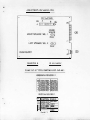
VEIn'ICAL MONITOR ''I''
CONNECTOR i\1
\0 \VA Y MOLEX 0.156" PITCH KEYWA Y PIN 4
1
j
2
3
4
5
6
7
8
9
10
VIDEO SYNC
WHT
KEYWAY
VIDEO
VIDEO
VIDEO
VIDEO
GND
BLU
GRN
RED
BLK/BLU
BLU
GRN
RED
HORIZONTAL MONITOR "2"
CONNECTOR N
,
j
10
WAY MOLEX 0.156" PITCB KEYWAY PIN 4
I
,
I
2
3
4
5
6
7
,
I
8
9
10
VIDEO SYNC
WHTIVIO
KEYWAY
VIDEO
VIDEO
VIDEO
VIDEO
GND
BLU
GRN
RED
BLKIVIO
BLUIVIO
GRNIVIO
REDNIO
•
PAGE 12
PAIn' No 12164
•
ELECTRONIC CREDIT BOARD
PINOUT INFORMATION
PIN COLOUR
1. YELlBLK
2. Me
FUNCTION
101'
MrCROSWITCIl OR N.P.N OPEN COLLECTOR INPUT.
MICROSWITCIl OJ{ N.P.N. OPEN COLLECTOR INPUT.
PNI' INPUT (MS I I I \SENTINEU
INPUT (MICROSWITCH)
INPUT (MS I I I ISENTINEU
INPUT (MICROSWITCH)
INPUT (MS 111\SENTINEU
INPUT (MICROSWITCH)
INPUT {MS 111\SENTINEU
VOLTS (lOp INlilBlT)
VOLTS (201' INHIBIT)
VOLTS (50p INHIBIT)
VOLTS (£1 INJ-III3lT)
VOLTS
VOLTS
VOLTS
lOp
lOp
3. WHlIBLU
20p
4. Nle
5. WHT\GRN
201 '
SOp
6. Nle
7. WHTIBLK
.sop
8. Nle
£1
£1
9. WH1WEl
10. BLUIBLK
o
o
11. BLU\YEL
o
12. BLUIORG
o
13. BLU\WHT
14. BLACK
o
15. BLACK
o
o
16. Me
17. KEYWAY
DC
+ 12"
18. ORANGE
DC
+ J 2v
19. ORANGE
DC
+ 12"
W. ORANGE
- POSITIVE COMMON FOR MSlll\SENTINEL
ll. BLU\VIO
METER OUTPUT (NPN OPEN COLLECTOR)
22. WHTIRED
CREDIT OUTPUT (NPN OPEN COLLECTOR)
23.0RG\BLK
o
VOLTS
14. BLACK
1) Use 0 volts for negative. common if plugging into MS 125 seperator uriit.,
2) Ensure that there is no coin meter connccted across any' input, ego via a '
1ll.c
.i roswitch or an adaptor card.
NOTE: On most uiligame adaptors pin 10 is linked 10 pin 24. and pin 11 is linked
to pin 25, these links should be removed completely. Then short pin t1 to
pin 12 on the adaptor card. l1us then uses the output from the credit board
meter drive.
3) The meter will always total cash in lOp lInits regardless of any credit
setting.
4) More than one coin mech may be fed into UlC PCB.
NOTES:-
c.g.
A)
B)
C)
D)
slO
SIO
slO
SIO
(up 10 four)
X MS 111
X MS 125
X Sentinel
5) Most credit -boards are supplied with a standard credit loom.
(Port No 16315) fitted with a male 6 way amp mate 'N' lock COlUlecior.
Pinouts arc shown below.
•
0;1
PINCOLOUR
ruNCTION
1. ORANGE
2. PINK
3. YEL/BLK
4. WHT\RED
5. BLACK
6.0RG\BLK
DC SUPPLY
+12\'
+5\'
DC (LAMP SUPPLY)
2nd COIN INPUT (SlO)
TO COIN METER
DC
Ov
COIN INPUT TO GAME rCB.
PAGE 13
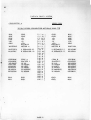
DIP SWITCH SElTlNGS v·2
•
FUNCTION
1
2
4
5
6
7
8
on
off
on
off
on
off
on
off
on
on
off
off
on
Not used
Bonus Gaines
N o",
For every SOp
For every £1
For every £2
3
on
off
on
off
on
on
off
off
I Pulse per credit
2 Pulses per credit
""
orr
Price per play
lOp
20p
JO p
40p
SOp
60p
£1
£2
on
on
off
off
on
on
on
off
off
off
off
Please Note:- A bonus game will only be awanJed if the game price of play is less than the
bonus value set. Also if a mixture of coins are inserted. the time interval
between coins inserted must be of less than 5 seconds for the bonus to be awarded.
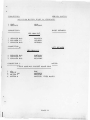
EXAMPLES OF SETTINGS (FOR £1 INSERTED).
•
,
Price of Play Bonus Games
I
lOp
lOp
lOp
20p
20p
20p
I
,
�
JO p
40p
40p
40p
SOp
SOp
orr
For every SOp
For every £1
orr
For every SOp
For every £1
orr
For every SOp
For every £1
orr
For every .sop
For every £1
orr
For every £1
Credits
Bonus
Total
10
10
10
NOn<
2
1
N On<
2
1
10
12
11
5
5
5
3
No",
3
2
No",
3
2
2
2
2
2
1
2
1
NOn<
1
•
•
PAGE 14
5
7
6
3
5
4
3
4
3
2
3
"
COLOUR MONITOH SETUP INSTRUCTIONS
L
HORIZONTAL FREQUENCY
With the monitor being driven with the display signal. conucct one jumper between TPI and
TP2 and another jumper between TP3 and TP4.
Adjust the horizonlal hold control until the picture stops sliding horizontally. Remove the
jumpers.
00 not use the horizontal hold control for horizontal centralizing.
NOTE:
2.
If the sync signal .is composite. use the horizontal sync input of the same polarity
as the composite sync signal.
PICTURE SIZE
Adjust the vertical size contro\. and the horizontal width coil for desired picture size.
3.
PICTURE CENTRALIZING
If the video is off centre vel1ically. tum the ver1ical raster position control to move the raster
up or down. If the video is off centre horizontally adjust the horizontal video shift control
to centre the picture. If any additional horizontal positioning is required. move the horizontal
raster position jumper to the len or right IlOsition.
l,
4.
BRIGHTNESS
Adjust the brightness control to obtain the proper illumination. Adjust this control such that
the illumination is just b.1rely extinguished from portions of the display which s1lOUld be black.
,
5.
•
CONTRAST CONTROL
Adjust the contrast control for the desired picture intensity.
6.
FOCUS
Adjust the focus control for the best overall dcrinition and
fine
picture detail.
""£III OMIV[
..... CU."H
nAST"E/I
1'OS1UON
"nil
..
,m
tlORll VtnEO
SHIFT
,
HOnlZ HOLO
•
•
7
VEIn RASTER PQS
V(RT SIZf·
VERT .1UI.1l
lIIIUJ"TN(SS
PAGE 15
j
I
t
•
HEMOVAL AND INSTALLATION OF HORIZONTAL MONIT01�
1.
I'i.:k mOllitor up using the slots 101:31«1 on c.1ch side of the monilor chassis.
Ihe neck of the Illonitor is facing away from YOll.
2.
Lift monitor onlo Ihc·front instruction shelf of lhe machine.
3.
Slide the edges of the monitor chassis underneath the lips of the two monitor brkts.
4.
Adjust your h.'looS so thai your Icft hand is on UK: top of the monitor, and your right
hand is underneath the monitor.
5.
Slowly lower the monitor into the nruchine, and onlo the (wo monitor brkts.
6.
Whilst lowering the monitor. care should [)e taken not to damage the tube neck of the
monitor on the shelf behind.
7.
The same instructions as above should be followed when rtmoving Ihe monitor from Ihe
machine. Only Ihis lime follow the instructions i n reverse order. Again care should
be taken not 10 dlllllage the tube neck of the monitor on the shelf.
(
•
I
SLOwtY LOWER MONITOR
ONTO TI£ TWO I3RKTS
ensure
thaI
lEFT fWU ON
TOP OF MONITOR
/
/ /'
'\1>----;Y
MONITOR NECK
RIGHT HAND
OOERNEATH
�TOR
INSTRUCTION
SIlli
•
•
,.
•
U1S i"IJI'iITm BRKT
flIRT NO. 201180
PAGE 16
.,
••
"
_
...._
�i�
�.·
.
•
,"""""
'io" '�'
ELECTROCOIN AF7ERSALES
&-
SER VICE LT.D
as part of the Eleclrocoin Automatics Group
at the Cardiff factory to provide the AftcrSales Service ncccssal)' to 9.lpport the
variety of machines manufactured by EIectrocoi n Automatics Ltd. The company will
be responsible for servicing both Spares and Teclu:tical �uirements for .11 UK.
manufactured Eledcocoin machines. all "Famous Games" products, and all Board
Games distributed by Eleclrocoin Ltd.
llle above company has been fonned
NonnaJ working hours
are
Monday to Friday 08.00 to
and Saturday morning OS.()O to 12..30.
17.30
Afte.rSates & Serviu Tel No: 0222 373059 during working hours,
0836 536195 after hours/weekends.
Please contact
the (aUowing staff for.-
PARTS ENQUIRlES
GARY SCOBLE
TECHNICAL INFORMATJON
IAN COlLEY
ACCOlMI'S ENQUIRIES
JULIE TIPPER
WORKSHOP MANAGER
MIKE CAll.AN
CREDIT CONTROLLER
IAN HEPPENSTALL
PLEASE REMEMBER. TO HELP US HELP YOU, PROMPT RETURN OF
FAULTY PARTS IS ESSENTIAL..
Assuring you of the best attention at all times.
JEFF LANGLEY
General Manager
ELECfRQCOIN AFTERSALES
& SERVICE LID.
•
'lI.....: