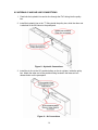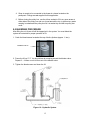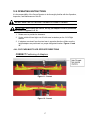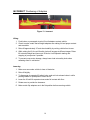
1
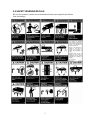
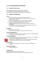
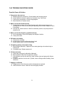
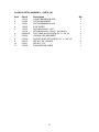
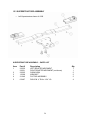
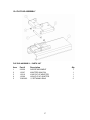
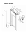
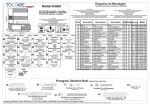
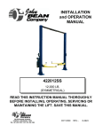
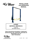
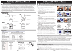
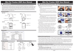
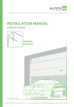
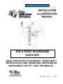
EELR504A, is a 10K 2post inground with stack pads INSTALLATION and OPERATION MANUAL 10K 10K 22 POST POST IN-GROUND IN-GROUND 40HP210ES 40HP210ES READ THIS INSTRUCTION MANUAL THOROUGHLY BEFORE INSTALLING, OPERATING, SERVICING OR MAINTAINING THE LIFT. SAVE THIS MANUAL. NOV 2009 REV. - 6-3667 Table of Contents 1.0 SAFETY AND OPERATING INSTRUCTIONS ........................................................... 3 2.0 SAFETY WARNING DECALS .................................................................................... 5 3.0 GENERAL SPECIFICATIONS .................................................................................... 6 4.0 SHIPPING CONTENTS .............................................................................................. 7 5.0 INSTALLATION REQUIREMENTS AND TOOLS....................................................... 7 6.0 BAY LAYOUT ............................................................................................................. 8 7.0 EXCAVATION ............................................................................................................. 9 8.0 INSTALLATION INSTRUCTIONS ............................................................................ 10 8.1 UNPACKING PROCEDURE ......................................................................... 10 8.2 LIFT INSTALLATION .................................................................................... 10 8.3 POWERPACK INSTALLATION .................................................................... 13 8.4 ELECTRICAL CONNECTIONS..................................................................... 13 8.5 HYDRAULIC AND AIR LINE CONNECTIONS ............................................. 14 9.0 BLEEDING PROCEDURE ........................................................................................ 15 10.0 FINAL CHECK OF ASSEMBLED LIFT ................................................................... 16 11.0 OPERATION TEST WITH VEHICLE ...................................................................... 16 12.0 OPERATING INSTRUCTIONS ............................................................................... 17 13.0 LIFT MAINTENANCE GUIDELINES....................................................................... 19 14.0 TROUBLE SHOOTING GUIDE............................................................................... 21 15.0 PARTS LIST ........................................................................................................... 22 15.1 CASING & PISTON ASSEMBLY ................................................................ 22 15.2 CASING & PISTON ASSEMBLY ................................................................ 24 15.3 SUPERSTRUCTURE ASSEMBLY ............................................................. 26 15.4 FLIP PAD ASSEMBLY ................................................................................ 27 15.5 HYDRAULIC & AIR ASSEMBLY................................................................. 28 16.0 POWER PACK ASSEMBLY ................................................................................... 30 17.0 AVAILABLE ACCESSORIES.................................................................................. 33 2 IMPORTANT * This lift requires at least 2 persons for assembly / installation. The use of a lifting device capable of safely lifting 2000 lbs is required for installation. 1.0 SAFETY AND OPERATING INSTRUCTIONS When using this lift, basic safety precautions should always be followed, including the following: 1. Thoroughly read all instructions in this manual and on the lift before installing, operating, servicing or maintaining the lift. 2. Inspect lift daily. Do not operate if it malfunctions or problems have been encountered. 3. Never attempt to overload the lift. The manufacturer’s rated capacity is shown on the identification label. Do not override the operating controls or the warranty will be void. 4. Before driving vehicles into the lift area, position the arms to the drive-through position to ensure unobstructed clearance. Do not hit or run over arms as this could damage the lift and/or vehicle. 5. Only trained and authorized personnel should operate the lift. Do not allow customers or bystanders to operate the lift or be in the lift area. 6. Position the lift support pads to contact the vehicle manufacturer’s recommended lifting points. Raise the lift until the pads contact the vehicle. Check pads for secure contact with the vehicle. Check all arm restraints and ensure they are properly engaged. Raise the lift to the desired working height. 7. Some pickup trucks may require an optional truck adapter to clear running boards or other accessories. 8. NOTE: Always use all 4 arms to raise and support vehicle. 9. Caution! Never work under the lift unless the mechanical safety locks are engaged. 10. Note that the removal or installation of some vehicle parts may cause a critical load shift in the center of gravity and may cause the vehicle to become unstable. Refer to the vehicle manufacturer’s service manual for recommended procedures. 11. Always keep the lift area free of obstruction and debris. Grease and oil spills should always be cleaned up immediately. 12. Never raise vehicle with passengers inside. 13. Before lowering check area for any obstructions. 14. Before removing the vehicle from the lift area, position the arms to the drive-thru position to prevent damage to the lift and or vehicle. 15. Do not remove hydraulic fittings while under pressure. 3 SAVE THESE INSTRUCTIONS For additional safety instructions regarding lifting, lift types, warning labels, preparing to lift, vehicle spotting, vehicle lifting, maintaining load stability, emergency procedures, vehicle lowering, lift limitations, lift maintenance, good shop practices, installation, operator training and owner/employer responsibilities, please refer to “Lifting It Right” (ALI/SM) and “Safety Tips” (ALI/ST). For additional instruction on general requirements for lift operation, please refer to “Automotive Lift-Safety Requirements For Operation, Inspection and Maintenance” (ANSI/ALI ALOIM). Installation shall be performed in accordance with ANSO/ALI ALIS, Safety Requirements for Installation and Service of Automotive Lifts. 4 2.0 SAFETY WARNING DECALS Be sure the operator is aware and understands all safety warning labels and follows them accordingly. 5 3.0 GENERAL SPECIFICATIONS Maximum Capacity: Maximum Capacity per Arm: Overall Width: Height to Lowered Lift Pads Height to Lift Pad (3” Adapter): Height to Lift Pad (6” Adapter): Height to Lift Adapter (9” Truck Adapter): Arm Extended Length: Arm Retracted Length: Maximum Lifting Height (No Adapter): Maximum Lifting Height (9” Truck Adapter): Lifting Time (approx.): Lowering Time (approximately): Power Requirements: Air Requirements: Oil Requirements: Shipping Weight 10000 lbs. 4536 kg 2500 lbs. 1134 kg 88” 2235 mm 4 ½” 114 mm 6 5/8 ” 178 mm 9 ½” 241 mm 12 ¼” 311 mm 41 ½” 1054 mm 28 ⅛” 714 mm 73 ½” 1867 mm 82” 2086 mm 63 sec. at max capacity 47 sec. at max capacity 230 Volts AC, 1 Ph., 60 Hz. 90 – 120 psi Shop Air 4.0 gal – ISO 32 (10 wt.) hydraulic oil 2300 lbs 1043 kg Figure 1 – Front view Figure 2 – Top view 6 4.0 SHIPPING CONTENTS The complete lift is contained in two (2) packages: 1. The main structural components are pre-assembled and packaged together onto one skid. 2. The remaining parts are packed in an accessory box. Refer to the packing slip inside for a list of contents. Components include: 1 – Complete casing and piston assembly 2 – Lifting superstructures (Left and Right) 1 – Accessory box (see Accessory box list for contents) 5.0 INSTALLATION REQUIREMENTS AND TOOLS Important: It is the user’s responsibility to provide a satisfactory installation area for the lift. Lifts must be installed level within the pit with a minimum concrete thickness of 10” the base of the pit ensuring that at least 6” of the concrete is encasing the bottom portion of the lift. Please consult the architect, contractor or engineer if doubt exists as to the strength and feasibility of the pit structure and footings. It is the user’s responsibility to provide all wiring for electrical hook-up prior to installation and to ensure that the electrical installation conforms to local building codes. Where required, it is the user’s responsibility to provide an electrical isolation switch located in close proximity to the lift that will enable emergency stop capability and isolate electrical power from the lift for any servicing requirements. 5.1 Tools Required • • • • • • • • • • • • • • • Lifting device capable of safely lifting 2000 lbs. Allen Key Set Ratchet & Socket Set SAE Wrench Set Phillips Screwdriver #2 Side cutters Rotary Hammer Drill ¼” Masonry Drill bit Impact Gun Torque Gun Funnel Tape Measure 6ft Level Caulking gun Tube of silicon sealant ** Fittings for running shop air to lift are not supplied. NOTE: Apply LOCTITE #242 on required fasteners where symbol is shown. If fasteners are removed, reapply LOCTITE before re-installing. 7 6.0 BAY LAYOUT 1. Make certain there is at least 70” between the lowest ceiling obstruction and the roofline of the highest vehicle to be raised. 12 ft. of ceiling height is sufficient for passenger cars. 2. A minimum of 12 ft. of stall space is required from the center of both front and rear of lift to nearest obstruction. Figure 3. 3. A minimum of 6 ft. is recommended between the center of the lift and side walls or nearest obstruction. 4. When determining measurements, take into account the areas required for work areas and benches. Figure 3 - Bay Layout 8 7.0 EXCAVATION 1. Excavate the location desired with minimum dimensions of 24”L x 84”W x 100”D as per Figure 4. 2. Dig a 9” deep trench (pipe chase for hydraulic and air lines) from the cylinder pulley box center fitting to the location you have selected to mount the pump and controls. Figure 4 – Plan and Excavation 9 8.0 INSTALLATION INSTRUCTIONS When the lifts arrives on site: • • • • Read the owners manual and make sure the installation instructions are fully understood. Check for any freight damages. Check the contents of the accessory and hardware boxes to make sure no parts are missing. Gather all tools required for installation ( Section 5.0) 8.1 UNPACKING PROCEDURE 1. Remove the plastic wrapping and metal ties. 2. Remove the accessory box and superstructures and place to the side away from the excavated pit. 3. Ensure all holes in the pistons and locking legs are covered. Do not spill any concrete, water or foreign objects into these openings. 4. Check the installation area for possible obstructions. (Lights, Heating Ducts, Ceiling, etc.) 8.2 LIFT INSTALLATION 1. Attach a lifting chain to the brackets on the upper spacer bar between the casings. Raise the lift slowly off the wooden skid and maneuver the lift to align with the pit. 2. Ensure the lift is rotated in the correct position so that the PVC fitting in the pulley box will be facing the side that the powerpack is located. Do not drill any holes in the pulley box to redirect the hydraulic and air lines. The lift must be rotated. 3. Slowly lower the lift into the pit. Secure the lift so that it is suspended into the pit ensuring that 1/4” will be above floor grade. Figure 4. 4. Place a 6’ level across the top of the pistons (not the casings or flanges), in both directions and adjust until the pistons are plumb. 5. Pour concrete around the base of the lift ensuring that a minimum of 10” is poured, with at least 6” encasing the bottom of the lift. Figure 4. Allow a minimum of 24hrs for concrete to cure. Refer to concrete specification for drying time. 6. Backfill the pit with a clean dry washed sand fill to a level just below the pulley box. Firmly tamp the sand during the filling process to ensure the sand is compacted and even. 10 7. In the 9” deep trench, layout PVC electrical tubing along the trench and up the wall to at least 6” above the surface. Figure 4 8. Install the PVC fitting and O-ring gasket to the pulley box and fit the electrical tubing inside the fitting. Ensure the assembly is fully tightened. Figure 5 - PVC Assembly 9. Using a silicon sealant and caulking gun, ensure all openings in the bottom and sides of the pulley box have been sealed and are water tight. 10. If the drain in the bottom of the pulley box has not been hooked up to a drainage system, fill hole with silicon sealant or install a 1-1/4” NPT plug. 11. Complete the backfill using clean dry washed sand to 9” below floor grade. Firmly tamp the sand during filling to ensure the sand is compacted and even. 12. After rechecking that the lift is level in all directions, the concrete floor can be poured. Ensure that the concrete is a minimum thickness of 9” with the lift at a minimum of 1/4” above floor grade. Taper the concrete away from the lift in all directions to ensure that water will be allowed to flow away from the lift. Ensure that the pulley box in the center of the lift has concreted tapered front and back. A taper of 1/8” over a foot would be recommended. It is also recommended to 11 slightly taper the concrete up the sides of the cylinders to prevent any standing water around the lift. 13. Install the wheel spotting plate using the ¼” anchors supplied in the hardware kit. Refer to Figure 3 for location. 14. Allow 48 hours before installing the lifting assemblies to the top of the cylinders. Use the 7/8” bolts to install the bolster plate to the pistons, and the ½” lockwasher and ½” hex bolt to secure the safety to the anti rotation tab. Apply loctite to threads on the bolts during installation. Figure 6 – Superstructure Assembly 12 8.3 POWERPACK INSTALLATION 1. Remove the red plastic cap located on the left side of the powerpack and install the 90° elbow provided in the hardware kit. 2. Secure the powerpack to the wall, in a predetermined location, using the ¼” anchors provided. The connection fittings should be at a minimum of 36” off the ground. 3. Remove the filler cap from the powerpack reservoir and fill the tank with 3.5 Gal (13L) of ISO32 hydraulic oil. (10 wt. hydraulic oil) 8.4 ELECTRICAL CONNECTIONS DANGER! ENSURE THAT ELECTRICAL CONNECTIONS ARE COMPLETED BY A LICENSED ELECTRICIAN! ELECTRICAL SHOCKS CAN CAUSE SERIOUS INJURY OR EVEN DEATH. 1. Connect the 230 Volt / 1 Ph power to the motor Figure 7 – Electrical Connections 13 8.5 HYDRAULIC AND AIR LINE CONNECTIONS 1. Feed both the hydraulic line and air line through the PVC tubing into the pulley box. 2. Install the hydraulic line to the “T” fitting inside the pulley box, while the other end is attached to the 90°elbow on the powerpack. Figure 8 – Hydraulic Connections 3. Install the air line to the 90° pushlock elbow on the air cylinder, inside the pulley box. Attach the other end to the pushlock fitting located in the brass air lock release button on the powerpack. Figure 9 – Air Connections 14 4. Shop air needs to be connected to the brass air release located on the powerpack. Fittings are not supplied for this application. 5. Before closing the pulley box, use the silicon sealant to fill in any open areas at either side of the pulley box and run a bead around the top, to prevent any water seeping in underneath the pulley box lid. Let sealant dry and bolt on pulley box cover. 9.0 BLEEDING PROCEDURE After filling the unit, there will still be trapped air in the system. You must bleed the system as instructed for proper operation of lift. 1. Crack the bleed screws located at the top of both cylinders (approx. ¼ turn). BLEEDER VALVE 2. Power the lift up 2”-3”. You should hear air escaping around the bleeder valve. Repeat 3 – 4 times or until oil flows out of the bleeder valve. 3. Tighten the bleed screws and lower the lift. Figure 10 – Hydraulic System 15 10.0 FINAL CHECK OF ASSEMBLED LIFT 1. Check for air and hydraulic leaks. ___ 2. Ensure all safety lock mechanisms are working correctly. ___ 3. Check all fasteners, tighten if necessary. ___ 4. Check that LOCTITE has been applied to all hardware where required. ___ 5. Operate lift to full stroke then lower to ground while checking for proper functionality. ___ 6. Ensure Customer Care Kit is complete and given to operator. ___ a. Operation Manual ___ b. ANSI / ALI Lift It Right Manual ___ c. ANSI / ALI Safety Tip Card ___ d. ANSI / ALI ALIS Safety Requirements for Installation and Service of Automotive Lifts ___ e. ANSI / ALI Quick Reference Guide ___ 7. Train end user on operation of the lift. ___ ___ 11.0 OPERATION TEST WITH VEHICLE 1. Lower lift to ground. 2. Drive vehicle on to lift and locate the arms as per the “Lift it Right” manual. 3. Raise lift to and lower onto 3-4 lock positions during full rise to ensure all locks are working correctly. 4. Re-adjust cables if necessary while vehicle is on. 5. Check lowering speed and smooth decent rate. 6. Lower lift to ground and drive vehicle off lift. If any problems occur during the final checkout or operation of the lift please contact customer service at 1-800-268-7959. 16 12.0 OPERATING INSTRUCTIONS It is the responsibility of the Owner/Operator to be thoroughly familiar with the Operation, Inspection, and Maintenance of this lift. DO NOT RAISE THE LIFT WITHOUT SUPERSTUCTURES ATTACHED. IMPORTANT: When lifting the vehicle, the flip pad adapters must be positioned as shown in Figures 11 or 12. 1. Rotate arms to provide tire clearance. 2. Center vehicle left and right over lift with arms located as per the “Lift it Right manual. 3. If adapters are raised, face front and rear in opposite directions. Make sure the height adapters are positioned in a proper designated location. Figures 11 and 12. • ALL FLIP PADS MUST FACE OPPOSITE DIRECTIONS CORRECT Positioning of Adapters Figure 11 - Correct Figure 12 - Correct 17 INCORRECT Positioning of Adapters Figure 13 - Incorrect Lifting: 1. Push button on powerpack to raise lift until adapters contact vehicle. 2. Check to make certain that all height adapters are making full and proper contact and are stable. 3. Raise lift approximately 18” and check stability by rocking vehicle front to rear. 4. While raising the lift, the air lift safety locks will engage at different stages. Raise lift to desired height and lower onto lift locks. Avoid sporadic starting and stopping of pump motor if possible. 5. To prevent pump motor damage, always lower load onto safety locks when restarting motor in mid-stroke. Lowering: 1. Make sure area under vehicle is clear of obstacles. 2. Raise lift slightly. 3. To disengage air-operated lift safety locks, push air lock release button in while pushing handle on powerpack to lower the lift. 4. Lower the lift until lift superstructures make full contact with floor. 5. Rotate arms to provide tire clearance. 6. Make certain flip adapters are in the flat position before removing vehicle. 18 13.0 LIFT MAINTENANCE GUIDELINES 13.1 SAFETY INSTRUCTIONS Read the operating and safety manuals before using any lift. Do not operate a lift that has been damaged or is in disrepair. Proper inspection and maintenance is necessary for safe operation. 13.2 PERIODIC MAINTANENCE DAILY: 1. Inspect all superstructure fasteners. Tighten if necessary. 2. Inspect arms for overload dropping from stretched or loosened arm bolts. Replace bolts if stretched. 3. Inspect the height adapters for damage and replace if necessary. 4. Check all electrical wiring for pinch points , cracks or damage 5. Check all moving parts for uneven or excessive wear. 6. Repair or replace all damaged, defective, worn or broken components immediately. 7. Raise and lower the lift at the beginning of each shift, without a vehicle on, to verify the lift is leveled and operating properly. BI-WEEKLY 1. Grease swivel arm rub bars. 2. Clean and re-grease glide block channels inside of both columns EVERY THREE MONTHS: 1. Lubrication of lift. Clean and wipe down pistons with a clean dry cloth and apply a silicon lubricant spray to the piston surfaces. EVERY SIX MONTHS: 1. Have cables examined for damage or fraying by a lift inspector. If any damage is evident, replace cables and DO NOT use the lift. 2. If cables are to be replaced ensure LOCTITE is to be applied to the threads of the cable & nuts located at the bottom of the safety ladder. EVERY YEAR: 1. Inspect lift as per Automotive Lift Operation, Inspection and Maintenance (ALOIM) EVERY TWO YEARS: 1. Change hydraulic fluid. LUBRICATION: Where grease is required > silicon based lubricant Where hydraulic oil is required > ISO 32 10W - non detergent hydraulic oil 19 13.3 MAINTENANCE SCHEDULE Records of all lift maintenance and operator training should be recorded in the following table. Maintenance and Training Performed Date By Notes 20 14.0 TROUBLE SHOOTING GUIDE Possible Cause & Solution 1. Pump motor does not run A. Breaker tripped or fuse blown. Check breaker and incoming power. B. Check thermal overload in starter box (3 phase only). Push reset. C. Faulty wiring connections. Check wiring diagram. D. Motor burned out. Replace motor. 2. Motor runs but the lift will not rise A. Contaminant in decent valve. Press descent valve while running pump to try clearing dirt from valve, by releasing and pressing several times. Replace if valve if necessary. B. Oil level low. Check reservoir. With lift in the down position, the pump reservoir should be full. 3. Motor runs but the lift picks up partial load only A. Lift is overloaded. Check lifts capacity and weight of vehicle. B. Faulty relief valve. 4. Oil blows out breather A. Oil reservoir overfilled. B. Lift lowered too quickly while under heavy load. C. Broken pickup tube or return line damage. 5. Lift makes groaning sound when rising A. Bleed cylinder manually. Trapped air can cause groaning noise when rising or lowering lift. B. Cavitated pump. Replace power unit. 6. Lift rises unevenly. A. Cables are not properly adjusted or tightened. B. Bleed cylinders. May have air pocket in cylinder. C. Outer pistons are very dry and dirty. Wipe surface clean and spray with silicone lubricant. D. Hydraulic restriction on one side. Cylinder, hose or fitting could be leaking. Hose restriction. 7. Sagging or stiff arms A. Sagging Arms. Arm bolts may need to be adjusted or replaced. B. Arms are hard to move. Clean rub rails and lightly lubricate. 21 15.0 PARTS LIST 15.1 CASING & PISTON ASSEMBLY 22 LIFT ASSEMBLY – PARTS LIST Item Part # Description 1 2 3 4 5 6 7 8 9 10 11 12 13 14 15 16 6-2445 1-3361 1-3358 2-2546 2-2547 6-3698 1-3360 6-0059 82546508 6-3532 4-1207 4-1206 2-2544 6-0126 6-0141 2-2549 ¾” RETAINING RING PULLEY ASSEMBLY PULLEY PIN 3-1/4” LG TRIGGER WELDMENT HOUSING WELDMENT 1/8” ALUMINUM CABLE CRIMP TRIGGER CABLE ½” LOCKWASHER ½” HEX BOLT x 2” LG. GR.8 7/8” HEX BOLT x 3” LG. GR.8 RIGHT SUPERSTRUCTURE ASSEMBLY LEFT SUPERSTRUCTURE ASSEMBLY TOP COVER ¼” HEX BOLT x ½” LG. ¼” NAIL-IN ANCHOR WHEEL SPOTTING PLATE Qty 23 4 2 2 2 2 2 2 2 2 8 1 1 1 4 4 1 15.2 CASING & PISTON ASSEMBLY * Left Piston & Casing Assembly shown 24 CASING & PISTON ASSEMBLY – PARTS LIST Item Part # Description 1 2 3 4 5 1-3312 3-1000 1-3331 1-3332 1-3333 1-3518 K82846J0 2-2538 6-3530 6-0673 6-3531 2-2539 CASING BEARING BLOCK PISTON WELDMENT PISTON BEARING BLOCK 8-5/8” WIPER RETAINING RING – LEFT RETAINING RING – RIGHT (not shown) FLAT HEAD ALLEN SCREW 3/4” x 1-3/4” LG LOCKING LEG WELDMENT SOCKET HEAD CAP SCREW 7/16” x 1-3/4” LG. HEX NUT 5/8” GRADE 8 HEX NUT 7/16” EQUALIZATION CABLE 6 7 8 9 10 11 Qty 25 4 1 4 1 1 1 4 1 1 2 1 1 15.3 SUPERSTRUCTURE ASSEMBLY • Left Superstructure shown: 4-1206 SUPERSTRUCTURE ASSEMBLY – PARTS LIST Item Part # Description 1 2-2530 2-2531 2-2525 1-3308 3-1040 6-3487 LEFT BOLSTER WELDMENT RIGHT BOLSTER WELDMENT (not shown) SWING ARM ARM BOLT FLIP PAD ASSEMBLY ROLLPIN ¼” DIA x 1/-34” LG. 2 3 4 5 Qty 26 1 1 2 2 2 4 15.4 FLIP PAD ASSEMBLY FLIP PAD ASSEMBLY – PARTS LIST Item Part # Description Qty 1 2 3 4 5 2-2529 1-3307 1-3310 1-3309 70452180 SLEEVE WELDMENT ADAPTER WING PIN LOW FLIP UP ADAPTER HIGH FLIP UP ADAPTER ½” RETAINING RING 27 1 1 1 1 2 15.5 HYDRAULIC & AIR ASSEMBLY 28 HYDRAULIC & AIR ASSEMBLY – PARTS LIST Item Part # Description Qty 1 2 3 4 5 6 7 8 9 10 11 12 13 14 15 16 17 18 19 20 21 22 23 24 25 3-0990 1-3473 6-1510 6-2095 1-3326 6-3488 6-3495 6-0714 6-3806 1-3471 6-3602 6-3603 6-3604 8-0141 6-0709 6-3523 1-3359 6-3490 6-3540 6-3170 6-3552 1-3365 6-3548 6-3549 6-0804 HYDRAULIC CYLINDER HYDRAULIC HOSE 138” FLOW CONTROL ¼” NPT MALE NIPPLE COUPLER 3/8” SET SCREW x 1” LG HOSE CLAMP HOSE GUARD BULKHEAD “T” 3/8” JIC FITTING HYDRAULIC HOSE 252” 1-1/2” LOCKNUT O-RING 1-1/2” PVC MALE ADAPTER ¼” DIA. POLYTUBE SWIVEL ELBOW, ¼” POLY x 1/8” NPT AIR LOCK CYLINDER CABLE END POWERPACK ASSEMBLY ¼” WEDGE ANCHOR x 3” LG 6-32 HEX NUT 12-24 SCREW x 3/4” LG AIR LOCK BUTTON BRACKET AIR LOCK BUTTON 6-32 SCREW 1-1/4” LG 90° ELBOW 9/16” SAE – 3/8” JIC 1 2 2 2 2 2 2 4 ft 1 1 1 1 1 21 ft 1 1 1 1 4 2 1 1 1 2 1 29 16.0 POWER PACK ASSEMBLY 30 POWERPACK – PARTS LIST Item. 1 2 3 4 5 6 7 8 9 10 11 12 13 14 15 16 Part No. 6-2298 6-0774 6-2158 6-1392 6-0916 6-2301 6-2157 6-2162 6-2164 6-2165 6-2166 6-3782 6-3553 6-1087 6-2159 6-2167 Description BOLT, 5/16” – 24” x 2-3/4” LG COUPLING (4 POST POWER PACK) SEAL SHAFT 0.5x1x0.25 CAPSCREW 5/16-18 x 1.00 SOCKET HD MICRO-SWITCH PACKAGE PLUG 9/16” SAE PLUMBING PLUG 9/16 SAE PLUMBING MAGNET SCREW TAPTITE TORX COVER ASY. SUCTION CLAMPHOSEADJ. INLET END HEAD UNIV. BLANK COVER VALVE CARTRIDGE CHECK WASHER 0.338x0.625x0.06 NUT 3/4"-16x1" HEX. 0.25 31 17 18 19 20 21 22 23 24 25 26 27 28 29 30 31 32 33 34 35 36 37 38 39 40 41 42 43 44 45 46 6-2168 6-1108 6-2169 6-2170 6-1091 6-3790 6-0884 6-1376 6-1089 6-3791 6-2154 6-0875 6-0782 6-3795 6-2153 6-0880 6-1846 6-2156 6-2301 6-2302 6-2151 6-2161 1-3365 1-3471 6-3548 6-3549 6-3550 6-0709 6-3552 8-0141 WASHER ¾" INT. TOOTH RELEASE HANDLE ASS'Y SHCS, M6x1 .35MM WASHER 1/4 LC HI-COLLR RESERVOIR SCREW TANK 3.0 GAL WHITE INLET HOSE/FILTER ASS'Y BREATHER FILLER CAP RELIEF VALVE CAP RETURN HOSE 1/2” O.D. x 19.00” COMP. TUBE SLEEVE RESERVOIR O-RING PUMP ASSEMBLY RELIEF VALVE ASSEMBLY 180 BAR COMPRESSION TUBE NUT VALVE CARTRIDGE RELEASE MANUAL CABLE TIE 8” LONG WHITE WIRING ASSEMBLY AC 1PH FENNER PACKAGE PLUG 9/16" SAE ELECTRICAL STAKON NUT SPRING 0.48x0.063x0.42 PLUMB. PLUG 3/8NPT AIR LOCK BUTTON BRACKET HYD. HOSE PUMP 2P/SING IN-GROUND AIR LOCK BUTTON VALVE 6-32 SCREW 1-1/4” LG AIR LOCK BUTTON VALVE NUT SWL. ELBOW, ¼” POLY x 1/8” NPT 12-24 ¾” HEX. HD SCREW TUBE, POLY., ¼” DIA. x 0.038” WALL 32 17.0 AVAILABLE ACCESSORIES Truck Height-Extension Adapter, Part No. 3-1028 (Set of 4) 33