1
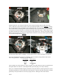
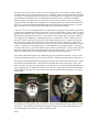
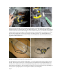
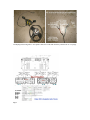
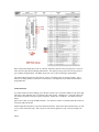
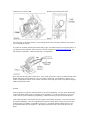
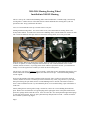
2010-2014 Mustang Steering Wheel
Installed into 2005-09 Mustang
This is a write up for a 2005-09 Ford Mustang audio control modification. It installs using a 2010 and up
steering wheel. It makes the use of the audio./SYNC controls and makes the steerring wheel your new
operations center. Keep you hands on the wheel.
Let’s see if I can make this write up so it make sense to everyone.
Starting with the steering wheel. You won’t be able to use your current 2005-09 steering wheel to use
factory audio controls. You will need a 2010 to 2014 Mustang wheel, with the double row switches on each
side. There are numerous write ups on how to remove the steering wheel, so let’s not go into that.
2005-09 Steering Wheel (GT shown above on left). What you will need to replace the 2005-09 wheel with
is shown, 2nd picture, or similar, using these radio switches (rt side of wheel) and these cruise control
switches (left side of wheel). If your strg wheel comes with the D pad on the left side, you would need to
change it out to the regular cruise control style switch as shown in this picture.
The air bag is your choice of whatever logo you decide. All the bags seem to interchange between the years
and all fit the same mounting places, using the same bolts and cover caps. I reused the running Mustang
Tri-bar original.
Now on to the internals of the wheel, with the air bag removed. Since you have to remove the wheels to
switch, I did mine on a bench. I found it just easier to work that way. How you go about it, is your choice.
Me I prefer having the open bench, not the crowded Mustang interior. Besides, who wants to solder in
there? Some could land in some very uncomfortable places, not to mention burning a spot in the leather or
cloth seats.
Start by taking the new steering wheel, using a Torx30 bit, remove the 3 screws holding down the horn
plate. Remove the red (both mine were) ground plug on the right upper corner of the plate and lift out the
plate and 3 springs that are under the screws. Set it off to the side. Now unclip both the right and left plugs
to each side control switch. These are just a push down clip and pull, but be careful. A small screwdriver
does wonders if you have big fingers.
Page 1
Wiring with plate removed.
Plate shown removed with bolts and springs.
With the harness out, you will clip off and remove the 10 pin clock spring connector (black with read
insert). Make sure to leave about 2 inches of wire to keep the plug reusable, in case of whatever. Separate
the two sides and leave the red and black wires together (don’t cut). The red is power for both sides of the
wheel, and the black is common ground. These two will hook to the 5 pin clock spring connector that has
to be put back on from the old wheel (or substitute from another donor like I used.). I didn’t want to tear up
my almost new 2005-09 GT wheel, so I used a plug from a late model Focus. The wire colors didn’t match,
but they run in a set series, so it was easy to figure out the connections, in case you want to go that route and
save your old steering wheel for whatever.
The first picture shows where everything is. The next picture shows it when its all together for reference.
Now, the red and black wires need to be connected to the 5pin connector, along with the cruise control
wires. They go like this: Original 5 pin to new harness:
New Harness
Old Connector
Gray
White
Brown
Blue
Black
Green or Black
Red
Red
There is another wire on the connector, it also is a ground. If you look closely you can see it attached to the
horn plate with the red connector. That completes that 5 pins on the plug. It is ready to finish up.
Once you’ve soldered and shrink wrapped your harness to the 5pin connector, bolt the ground wire eyelet to
the marked “ground screw” shown in the above left side picture. This gives the whole strg wheel a common
ground loop. The 5pin connector is now ready to plug to the car. Moving on to the radio controls.
Page 2
There are 4 wires in this system. There are 6 wires in the plug, but one is red and one is black, which are
already hooked up, so you only use the other 4 wires. Some have 2 more wires, but with what we are using,
4 is perfect. Use a Motorcraft WPT1242 connector to attach both the lower and upper clock spring plugs.
The old number was WPT440 (most are familiar with this number but like everything else, things &
numbers change). You will need any 4 of the 6 wires to make it work. Whichever you use, you have to
exactly match the other WPT1242’s configuration, so everything matches up. I left the first and last wires
open, in case I wanted to add or change anything since I am making my own harness anyways. You can
make any combo out you want, just make sure to match the second connector exactly.
I took the 2nd and 3rd wires and made them for my audio positive and negative wires needed to go into the J1
connector in the ACM (radio head 24 pin connector). These are used on SWC1 systems. SWC2 use other
plug in points in the head. Wire 2 goes into the (Gy/Ye) #18 slot and wire 3 (Bn//Gn) into #19. Navigation
heads require the pins going into #16 & #17. Wires 4 and 5 were originally given to the wires going into
the J3 plug, but since I didn‘t have a Shaker head anymore, I needed to use #16 & #17 instead. You are
best off, if you run a ohm meter on the 4 wires to tell which is which to be safe. I set mine up so that the
one on the top row (plugged in) was the positive and pin directly below was the negative. The red and
black are already taken so you only have the 4 wires to worry about. Check which is which before you tape
it all up. It would best be safe, than sorry later. I cannot find the color to pinout anywhere. I just lost it.
Just ohm out the first wire, see which control it works, and the rest fall into place. The one on the same row
nest to that would be the other positive and the bottom other the other negative. Also the wiring colors
listed, are from the factory service manual, and are at the ACM, not the steering wheel.
Now soldered and shrink wrap all 4 wires and set the plug up to go under the horn plate. Wires 1 & 6 are
taped on the ends and put away in case of need or want later. You know, different switches, different toys.
Now plug in both the right and left harness plugs into the strg wheel switches and route the wiring so that it
won’t interfere with the horn plate. This can be tricky and tight with a lot of shrink wrap or tape, or use
what is necessary, and don’t over wrap anything. It’s tight in there. Set in the horn plate, and reattach the 3
bolts. Tighten securely so that the horn doesn’t come loose later. Plug in the horn connector on the upper
corner, and make sure your wires run to the two hole in the strg wheel for them specifically. See second
picture below.
You now have a steering wheel ready to go into the car, but you still need another jumper harness to make
this work out. This is where the second of the WPT1242’s comes in. It has to be made with the same 4
wires that match up to the harness you made for inside the wheel.
Page 3
On the lower left side of the steering column, facing the dash, you will find another plug, just under the
headlight control lever, which is where the other WPT1242 goes into. You will need to add about 24 inches
of wire to each of the 4 wires to have enough to fit. On the ends of each wire, you will need a female spade
terminal connector for the Ford plug. I took another connector, and took out the wire terminal, so I would
have the correct fitting ends. It takes a bit of practice, but with a good tool, very small flat blade screw
driver, you can get them out. Once you have 4 ends, you can attach them to the wires and then you have to
plug them into the ACM harness.
.
Harness I made up (above) showing the 4 leads. Second picture shows clock spring with WPT1242
attached. This harness is run up to the ACM connectors.
My made up harness with 4 end leads and disconnect. The clock spring showing where the lower harness
attaches. Note in picture 2 below, the J1 connector pins go into different slots if navigation head is used.
You have to be careful, since Ford uses many different setups, that you use #18 & #19, then which of the
other pairings you might need. They will either be in the #16 & #17 pair or the #4 & #5 pair, depending on
the way it is set up originally and if it is navigation or Shaker (6 disc audiophile).
Page 4
Clockspring and steering wheel. Next picture shows the 4 leads and where they attach to the J1 or J3 plugs.
Page 5
Back of radio head and pictures of the J1 connector, marked to show the #18 & #19 pin points. These are
where the wires plug into the Mustang radio harness. The other two pins go into ports #16 (neg) and #17
(pos) with the navigation head. The Shaker shows 4 & 5 in J3, but I am starting to question that.
The Taurus radio head, the wires show that J3 is where you add the wires for the radio controls. I have
marked it as fitting ‘shaker” but that isn’t necessarily true. It all depends on your radio head and what is
programmed to it.
SYNC INSTALL
If you have SYNC kit and are adding, now is the time to hook it up. The SYNC module ties up on the right
side of the center dash stack area. It is held on with 2 long zip ties. Nothing more. You need to drill your
left console trim panel (removable console side panel). It takes an 11/16 drill bit. You drill near the top
Page 5
upper corner a hole to accept the HMI controller. You also have to drill a ¾ inch hole inside the console to
accept the USB cable mount.
Pull the right side kick panel to expose the Smart Junction Box. Pull it down and on the back side, you will
see a red wire with a blue stripe. This is keyed to work with the ignition on only. Hook your single wire
here.
Page 6
Red/blue wire on back of SJB
Drill hole in left console trim panel
This will power up the SYNC module. You next hook the two wires to the DLC and check the system to
see if everything is working.
If you have no problems, button up the interior and go enjoy your hand controls on your steering wheel. If
you should have any questions, that I can answer, feel free to email me at [email protected]. No
solicitations a offers please. Only about this setup. NO Spammers.
DTC connector showing where to hook wires. These solder into the DLC and are accessible thru the SYNC
module and proper software/hardware. Once everything is hooked up, you should have control of your
SYNC, steering wheel controls, cruise control (of course), and overall, just a better set up than the original
Shaker 500 that came with it.
NOTES:
Some people have run into the common problem of incorrect programming. The new SYNC module that
comes in the 9R3Z-14D212-A kit, is basically a start up module. It “can be programmed” to your exact
vehicle, but isn’t perfect without the programming. Some functions may or may not work all the time.
I have found, and others on YouTube also, have gotten a used module (9E3T-BC, or CE codes will work
best with the Mustangs). These are programmed to fit SYNC vehicles and as long as you get the second
generation plug type module, you should be good to go. I used the BC module and have perfect voice
recognition and does what it’s suppose to. Wrecking yards and other places have them for $50 on up.
Page 7
You can’t go to the dealer for that and have your radio reprogrammed. Most of the dealerships won’t even
do the work. This is a cheap alternative to the problem. The 14D212 kit, when bought from a guy on eBay
sells for about 65 or so delivered. Add a $50 module, and you still have a very inexpensive set up. You
can always sell your module on eBay and get some money back.
Doing this was sort of a nightmare to figure out, but with enough of the go juice, it finally got done and now
written. If anyone tries this, and if you have problems, note what they are so we can update this and maybe
keep everyone trouble free.
I hope that this helps some of you guys out with this project. Bill
Page 8