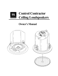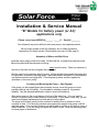
1
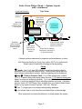
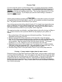
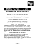
Piston
Pump
Solar Force
TM
Installation & Service Manual
“B” Models for battery power (or AC)
applications only
Please record your MODEL #_______ -_____B
Serial # ________
Your shipment may arrive with the motor and pump in two separate parcels.
We no longer include oil with the shipment, due to safety regulations
imposed by our freight carriers. Please obtain your own oil (see page 3.)
Assembly of Motor and Belt Drive
Install the motor pulley on the motor shaft. Oil the shaft first, to make future removal easier.
Mount the pulley with the setscrew end facing
away from the motor. Place one setscrew in
the slot on the shaft, but do not tighten the screws yet.
Bolt the motor to the mounting blocks, loosely. Hold a straight-edge against the motor face
to check that it is parallel to the large pulley. Adjust belt tension for about 1/2 inch deflection,
and tighten the motor mounting bolts. Turn the pump by hand, and then tighten the
setscrews on the motor pulley.
Locating and Mounting the Pump -- See Diagram
If the pump is to be located higher than the water source, mount the pump as low as
possible (without risk of flooding). It is desirable to minimize suction lift, for greatest
reliability. See the attached specification sheet for suction lift limitations.
Allow easy access to the round plate on the front of the water box. You may need to
remove it to replace piston seals (leathers) occasionally. If your water is very dirty, you will
need more frequent maintenance so leave plenty of work space.
The pump and the belt guard must be screwed or bolted down to a base of wood,
concrete or steel. Your mounting structure must support the weight of the pump, and the
attached piping. Your mounting structure should be able to hold up for 20 years or more, in
damp conditions. If it is not strong, the pump will shake it loose. Level the mounting base,
to insure proper oil distribution.
-- Page 1 --
Solar Force Piston Pump -- System Layout
with clearances
Corner Wall Clearance:
(Mirror may be used to
inspect oil
window.)
Top View
6 in.
Belt Guard
requires 12 in.
clearance above
it, for removal.
Leave space
open here for
servicing rod
seal, oil, belt
drive and motor
brushes.
Water Box
Leave clearance
above and below
to service pump
valves.
(pressurizing
systems only)
Check
Valve
Union
A
Pressure Tank
C
Gate
Valve
D
B
Accessory Tee
holds Pressure Switch,
Pressure Gauge and
Drain (hose) Valve
E
Leave space
open here for
servicing cup
leathers.
Surge Tank (if required)
mounts here, requiring 15
in. vertical clearance.
Observe minimum clearances for inspection and maintenance, as show.
Bolt the pump directly to a strong, firm surface, NOT on on rubber pads.
Expect traces of water and oil leakage at the rod packing.
Piping
A
Intake: Use 1 1/4" pipe OR LARGER (consult a pipe sizing chart to
determine a size for very low pressure drop). Treat this much like a drain line.
Avoid humps to eliminate air pockets. See text regarding suction limitations!
B
C
and
Outlet to Pressure Tank: For a 3040 model pump, install a
1 1/4" X 1" reducer fitting at the pump outlet, then use 1 1/4" pipe and check valve.
Keep it as short and straight as possible. Try to use 45° elbows instead of 90°
elbows. Low friction piping will help to eliminate pulsation and noise. If pulsation
persists, install a ST-3000 Surge Tank, available from your Dankoff Solar Pumps
dealer, or any expansion tank of around 1 Gal. size. See text.
D
Use 1" or larger pipe in accordance with plumbing standards.
E
(not shown) Pipe or hose from Pressure Relief Valve to safe drainage.
Store spare parts and Instruction Manual in a clearly marked box nearby.
-- Page 2 --
Expect some water to drip from the rod packing. Traces of oil may also leak from the
crankcase, around the shaft and window. Mount the pump so that it cannot leak into your
water supply. If that is not practical, place some rags under it, to absorb oil and water that
may drip.
Place the belt guard over the belt drive assembly. Position it so that the pulleys turn freely,
then screw it down to your mounting surface.
WARNING:
DO NOT OPERATE PUMP WITHOUT BELT GUARD IN PLACE.
Catching a finger or loose clothing or hair in the mechanism
can lead to serious injury.
Shelter your pump from rain, dirt and hot sun, as well as from children and other wildlife. If it
is outdoors, provide a good cover. Leave some air space around the motor for cooling. If
you insulate the pump for freeze protection, do not wrap insulation around the motor.
Adding Crankcase Oil
Do not run your pump until you have added 8 oz. (240 cc) SAE 30-weight (ISO 100) oil to
the crankcase. The best oil is hydraulic oil with good water-resistance. You can also use air
compressor oil or motor oil. To add oil, either remove the brass plug above the clear sightwindow, or remove the sight-window. Bring the oil up only to the bottom edge of the
window. Any more will leak out.
Intake Plumbing
It is most important to minimize resistance to flow on the intake side.Place the pump as near
as possible to the water supply. Model 3040: Your intake pipe must be no smaller than
1 1/4 inch size (the size of the intake port on the pump). Models 3010 & 3020: You may
reduce down to 1 inch pipe if you wish. If intake pipe is more than 25 feet (8m) long, and
yours is the higher flow model (#3040), then go one size larger.
Do not restrict intake with undersized pipe or suction lift beyond specified limits. Doing so
will cause "cavitation" (formation of vapor bubbles). A slapping sound is evidence of
cavitation, which will cause excessive wear and loss of performance.
Do not use flexible hose that crushes or kinks easily. Do not allow intake to draw sediment
from the bottom of water source. Avoid humps in the intake pipe. They can cause air
pockets that will obstruct the flow of water. A gradual incline is best.
If your pump is placed higher than high-water level in your water source, you will need a
foot valve, available from any pump supplier. You will also need to “prime” the pump by
pouring water into the port marked “prime” on the pump. The idea is to completely fill the
intake pipe so that the pump does not have to pump air in order to draw up the water.
Shutoff Valve: If your pump is placed lower than your water source, install a shutoff valve
to stop water flow when you are working on the pump.
Foot Valve: If your pump’s intake is to be higher than the water source, it must have a
check valve or a foot valve at the intake. These items are available from your local pump
supplier. See “priming”.
Screening Debris: If your water contains sand, consider the addition of a sand screen. If
your water contains various debris, use a foot valve with a large intake screen. This will
keep out large particles and sticks that can catch in your foot valve. Near the pump’s intake,
you can add in-line screen or disc filter to catch finer debris where it may be cleaned out
easily. Contact pump or irrigation suppliers for these items. It is not necessary to filter the
water to a totally clear state. Your pump can tolerate a moderate amount of sediment.
-- Page 3 --
Outlet Plumbing
A check valve must be installed at the pump outlet. This will make the system more
efficient and easier to service, and will prevent continuous leakage at the rod packing. Use a
spring-loaded check valve with a rubber seat.
If your outlet pipe is long, you will need to increase the size to larger than 1 inch. Look at a
pipe sizing chart or ask your dealer for advice. Also see “Surge Tank” option.
Electrical Wiring
Low voltage power requires larger wire than conventional 115 Volt power. Consult a low
voltage wire size chart, or ask your dealer for wire size recommendations. Undersized wire
will reduce pump speed, and may be hazardous. Always follow the National Electrical
Code®. If you are not experienced with electrical installation, hire a qualified electrician.
Motor Wiring, DC Models
1/2 HP models: Red = Positive Black = Negative.
1/4 HP models: White = Negative Black = Positive
Direction of Rotation: Clockwise.
If motor turns in the wrong direction, reverse the wiring.
115VAC Models: To reduce shock hazard, connect the green wire to
a grounding conductor in accordance with electrical codes.
Protection from Electrical Overload
A mechanical or hydraulic fault in your system can cause motor overload. If protection is not
provided, this can cause damage to your motor or other parts of your power system,
including fire hazard. A circuit breaker or fuse is the electrical “safety valve” that prevents
such damage.
Failure to install a proper fuse or circuit breaker
will void your warranty.
A circuit breaker is better than a fuse. Most AC breakers cannot be used for DC circuits.
We recommend only Square-D® QO or QB-Series breakers. They are commonly
available at electric supply stores and are UL-listed for low voltage DC up to 48V.
If you use a fuse, use either a plastic plug type automotive fuse (24V, 30 Amp Max.) or a
cartridge type time-delay fuse the same as used for AC power. Do not use the small glass
type of fuse. Keep spare fuses nearby. DO NOT substitute a larger fuse if there is a
problem.
Amp Rating of fuse or breaker: The breaker of fuse must be rated NO MORE than 10%
higher than the “Amps" rating on the motor label.
Place the fuse or breaker close to the power source, rather than at the motor, so that it
protects the entire wire run from faults, as well as the motor.
-- Page 4 --
Pressure Switch
If you are using this pump in a pressurizing system, you need a pressure switch, available
from any pump or electric supply, or from your dealer. You may use the type used for AC
pumps. 1/2 HP models require the large “heavy duty” size. The pressure switch
determines at what pressures your pump will turn on (cut-in) and off (cut-out). You may
adjust your switch to your liking, or leave it set at the factory settings. The lower the
pressure, the less energy will be required.
Ground
+
Ground
+
DC Power
Source
Pump
First-Tall Screw:
Adjust this one to set
both cut-in &
cut-out pressure. Set
it for the cut-in that
you desire.
Counterclockwise will
lower the setting.
Second-Short Screw:
This one adjusts
cut-out pressure only.
115VAC Models: Wire exactly as above. White is “neutral” and black is “hot”.
Explanation: The National Electrical Code® specifies that switches not disconnect the
“grounded conductor”, which is the negative. So, we are switching only the positive. Using
both sets of contacts as shown (wired in series) will extinguish the arc (spark) that forms
when the contacts break. This greatly increases switch reliability.
-- Page 5 --
Pressure Tank
If you are using this pump in a pressurizing system, you need a pressure tank, available
from any pump supplier, or from your dealer. Use a MINIMUM 40 GALLON sized tank.
Important: Adjust the “precharge” air properly. You must do this with water exhaused
from the tank, so that your water pressure is zero. Then, set the air pressure to 2 or 3 PSI
below your cut-in pressure. If you readjust your pressure switch settings, remember to
adjust the precharge again.
Surge Tank
A piston pump produces a pulsating flow. A surge tank is a tank with a cushion of air inside
(a small pressure tank) that takes water in and out, and completely smoothes the pulsating
flow. This greatly increases the efficiency of your system.
Your existing pressure tank will provide this function IF it is located very close to the pump
(with no more than one or two elbows between the pump and the tank) AND IF it is no
larger than 45 gallons. Otherwise, add a surge tank . In any case, if your pipes shake or if
you observe pressure pulsations in your system, add a surge tank.
The surge tank contains an air bladder, much like a balloon inside, with a tire-type air fitting on
top. In order to function, the air pressure MUST be set properly for your system, as
follows:
1. Be sure that there is NO water pressure at the tank’s pipe fitting. The tank can be
detached from the pump to do this.
2. Measure and note the existing air pressure in the surge tank, using a tire gauge.
3. Note the CUT-IN pressure as determined by your pressure switch (typically about 30
PSI). Is there much vertical lift from the pump outlet up to your pressure tank? If so, add
the lift pressure: Note the vertical lift (feet) from the pump to the tank. This number
divided by 2.31 = PSI. Add this to your cut-in pressure for the next step.
4. Adjust the air pressure by letting some air out, or pumping more in, to approximately
ONE HALF of the cut-in pressure (PSI). This setting does not need to be exact. If it is
too high, the air bladder will be too hard, and will not act like a cushion.
5. Screw the Surge Tank in to the port marked “Prime” on top of the pump water box.
Priming -- If pump intake is higher than the water source
Remove the plug (or surge tank) from the port called "prime", and pour water in while pump
is running, then reinstall the plug. This is an outlet port, but water will seep through the outlet
valves when they are not under pressure, and fill the cylinder. If any point on the intake line
is higher than the top of the pump’s water box, install a pipe tee and plug at that point.
Remove that plug to prime the pump. You must displace any air that may get trapped in
the high point on the intake line. Install a check valve or foot valve at the base of the intake
line so that it holds prime.
-- Page 6 --
Startup Proceedure & Servicing the Leather Cup Seals
DO NOT RUN THE PUMP DRY. If it does not work after priming, it may be because the
leather seals are dry. They need to soak up water and expand. If it still doesn't work,
remove the piston and stretch the leathers with your fingers, then replace them in the
cylinder. 3040 Models: Use your spare brass cylinder as an installation guide.
If pump is pushing only 1/2 capacity and pulsating, one leather is not sealing. It will usually
seat itself in a short time. If not, remove the piston and stretch leathers again.
You will need a 3/4 INCH SOCKET WRENCH and straight pliers to service the leathers.
When unscrewing the piston, the piston rod may turn and come out with it -- no problem.
When replacing the piston assembly, screw it in firmly. WARNING: DO NOT tighten the
piston very much, or the “piston follower” (part #19) will crack.
Run-in: Your new pump may be stiff at first, causing higher current draw than anticipated.
This will correct itself as parts wear in.
A new belt will stretch after the first few hours of use. Re-tighten as necessary.
Adjusting the Packing Nut
The piston rod enters the water box through a packing seal. When you first start your
pump, it will leak. While the pump is running, tighten the packing nut. You may use the
wrench supplied with your pump. Tighten it until the pump slows down substantially. This
will compress the packing. Now loosen the nut slightly, until the pump runs faster and is
slowed only very slightly by the packing pressure. There should now be little or no
accumulation of water.
Pressure Relief Valve
A Pressure Relief Valve is supplied. This is an important safety device that must be
installed on the front of your water box, above the round plate. If your pump’s outlet is
ever blocked, excessive pressure will build, and water will escape from this valve. Fit a
pipe or hose to the valve to conduct water safely away to prevent water damage should
the valve open. Position the valve so that its outlet does not block access to the round
cover plate. The valve is factory pre-set for 80 PSI (180 feet / 55 m). If you are pushing
more pressure (total lift) turn its adjustment screw clockwise until water leakage stops (no
further). To reach the adjustment screw, remove the flat front cover screw (stamped “100
psi”). You will see the adjustment screw inside.
MAINTENANCE
Parts of your pump will wear with normal use. Your pump came with a box of spare parts.
Keep it labeled and stored in a safe place so it can be found years from now.
(1) TIGHTEN THE PACKING NUT around the piston rod when water leaks too much.
Tighten it lightly, while the pump is running. Do not overtighten it, or more power will be
consumed. It will always leak slightly.
(2) CHECK BELT TENSION. Belt should deflect no more than about 1/2" (12 mm). A
repeating groaning noise indicates a slipping belt. Tighten it immediately.
(3) PUMP LEATHERS are the seals that form the heart of the pump. When they are
worn, the pump will turn faster, draw less current, and pump less water. Order them
from your dealer or factory, or other pump supplier. They are similar to those used in
windmill and hand pump cylinders. Do NOT use rubber seals. They cause excessive
friction and may cause sand particles to scratch the cylinder wall. When replacing
leathers on Model 3040, use your spare brass cylinder as an insertion guide. See
“Starting the Pump & Servicing the Leathers”.
-- Page 7 --
(4) CHECK OIL LEVEL. Keep oil filled ONLY to the bottom of the inspection window.
(5) CHANGE OIL every 2 to 5 years, depending on use. Use 8 oz. (240 cc) SAE 30weight (ISO 100) oil. The best oil is hydraulic oil with good water-resistance. You can
also use air compressor oil or motor oil. If the oil develops an opaque light-brown
(milky) color, it is contaminated with water and must be changed immediately. Wipe out
the crank case to remove water, and leave it open to dry out before you refill it.
(6) CHECK ROD WIPER (see diagram, part #57). This is a rubber disk on the piston rod.
It prevents water from leaking into the crank case and displacing the oil. It MUST FIT
TIGHTLY on the piston rod so it MOVES WITH THE ROD. If it is loose on the rod,
GLUE it to the rod using silicone sealant or similar rubber adhesive.
(7) CHECK MOTOR BRUSHES. These are small blocks of carbon-graphite that make
the contact to the spinning part of your motor. When they wear out, the motor will stop
completely, as the circuit is broken.
1/2 HP models: Remove the two curved plates on the rear of the motor. The brushes
are held in with clips that are easy to remove with your finger. New brushes measure 1
1/4 " (3 cm) long. When your brushes are worn half-way, replace them. Brushes
should last about 10 years or more. After a few years you can measure your wear and
predict the life expectancy.
1/4 HP models: Remove the two plastic screws on the rear of the motor. Be gentle!
Pick out the metal piece and withdraw the brushes. New brushes measure 3/4” long.
Replace them before they wear to 1/4”. They should last about 5 years or more.
Storing and Restarting Your Pump
If you will not be using your pump for periods of 2 months or more, please drain it. This will
allow the leathers to dry so that they don’t grow mold or mildew, and will prevent heavy
accumulation of rust. Remove one of the plugs under the water box. Remove the round
cover plate on front of the water box, and then remove the piston assembly using a 3/4”
socket wrench. Replace the cover plate loosely to keep rodents out.
To restart the pump, soak the piston assembly, stretch the leathers out, then replace it in the
cylinder. See “Startup Proceedure”.
Long-Term Care
Crankcase Oil: If your pump runs all-day, please change the oil during the first year. After
that, change oil at 2 year intervals. Check for contamination: See #5 and #6 under
Maintenance, above.
Cup Leathers: Leathers may last for 5-10 years. However, we recommend changing
them periodically to protect your cylinder. Leather is used because it can absorb particles
of dirt that would otherwise scratch the cylinder. If the leather becomes saturated with
abrasive material, it acts like sandpaper. We have a customer who pumps water that looks
like creamed coffee. After about 2000 hours with the original leathers, the flow began to
diminish due to grooves worn in the cylinder.
Even clear water may contain occasional particles of sand, or traces of clay. You can easily
inspect your cylinder by removing the round plate from the water box. Turn the pulley to
draw the piston inward, then feel the cylinder wall with your finger. If it is not very smooth,
then replace your cup leathers at more frequent intervals.
Valve Parts: The rubber valve discs will wear if the water is dirty, but will generally last for
5000-10,000 hours. Replace them if they develop any cracks. Replace the valve springs
at the same time.
-- Page 8 --
Tools: Keep these tools at hand for inspection and maintenance:
Wrenches
Packing Nut Wrench (included with pump)
(or substitute 1 1/8” open-end)
7/16”, 1/2” and 9/16”, box-end wrenches
Socket wrench with 3/4” deep socket
(or shallow socket with short extension)
Pliers
Common straight slipjoint type
Screwdriver
phillips head (1/2 HP models), or flat head (1/4 HP models)
to fit motor brush covers
Pipe Wrenches
as appropriate
Operating Solar Force by Hand
You may operate your pump by means of any mechanical power source that will turn the
pump pulley. To work it by hand, attach a lever to the pulley. You need only to work it
back and forth within a 90° arc. Make a handle of wood or metal (square or angle stock).
Drill two pairs of holes, and use small U-bolts, or bolts with a metal plate, to mount the
handle to the pulley. Position the lever so that its motion causes the the piston rod to move
through its full stroke.
-- Page 9 --
History
Brass cylinders with leather cups have been used to pump water since the dawn of the
industrial revolution. Double-acting piston pumps similar to ours were very popular for
pumping shallow wells and for pressurizing, from the 1920’s to the 60’s. Old folks have
told us that they had piston pumps like this that lasted 30 years!
Cheaper submersible and jet pumps took over the market by the 60’s. The modern
pumps have one moving part, and require no maintenance. The problem is, they consume
twice as much energy. The piston pump has two other advantages. One is that we can
use our choice of DC motors. Another is that it can develop full pressure even when turning
very slowly. We use this advantage on our solar-direct pumping systems. It is curious to
note that we had to look to the past to utilize the energy source of the future.
We have sold our Solar Force pumps since 1989 with terrific results. It is rare for any of
them to need any more than the inexpensive parts included in our parts kits.
Regarding 115VAC Models Only
Your motor is a DC motor. AC power is converted to DC by a “rectifier” in the
junction box on the motor. If you have a long power line leading to your pump, it
may be susceptible to high voltage surges induced by lightning. Surges can
destroy the rectifier. Observe proper grounding and install a lightning arrestor at each
end of your power line. You may obtain such devices from a pump supplier. A
failed rectifier will usually causing a short-circuit , blowing your fuse or breaker. If you
obtain one from an electronic supplier, be sure it is rated at a high voltage. We use
“1000 PIV”, 15 Amps or larger.
KEEP THESE INSTRUCTIONS IN A DRY, SAFE PLACE
You will want to refer to them years from now.