1
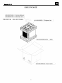
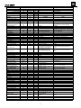
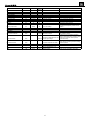
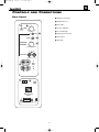
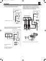
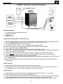
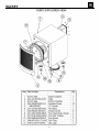
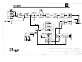
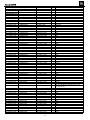
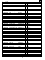
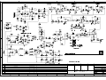
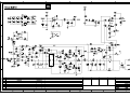
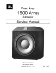
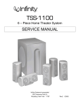
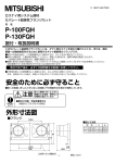
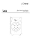
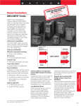
Venue™ Series
SUB12
Amplifier/Subwoofer
SERVICE MANUAL
JBL Consumer Products
250 Crossways Park Dr.
Woodbury, New York 11797
Rev0
7/2006
Venue SUB12
- CONTENTS -
BASIC SPECIFICATIONS……………….….….….….…………….1
PACKAGING…………………………….………………………......2
DETAILED SPECIFICATIONS
……..…………….……………..3
CONNECTIONS..……………………………………………………5
OPERATION ………….……………………………..…………….7
TEST SET-UP AND PROCEDURE……………………………….8
EXPLODED VIEW/PARTS LIST…………………………………..9
BLOCK DIAGRAM..……………………………………….…........10
120V ELECTRICAL PARTS LIST ……………………………….11
PCB DRAWINGS………………..………………………………...14
INTEGRATED CIRCUIT/TRANSISTOR PINOUTS……………..16
120V SCHEMATICS.……….…………….…………..…. ………17
BASIC SPECIFICATIONS
SUB12 Subwoofer
Frequency response:
25Hz – 150Hz
Amplifier Power output:
250W Continuous RMS power
Amplifier Peak Dynamic Power†:
500W
Crossover Frequencies
50Hz – 150Hz, 24dB/octave, continuously variable
Woofer:
12" (305mm) PolyPlas™ cone
Dimensions (including grille):
19-3/4" x 14-3/8" x 18" (502mm x 365mm x 457mm)
Weight:
39.5 lb/18kg
† The Peak Dynamic Power is measured by recording the highest center-to-peak voltage measured across the
output of a resistive load equal to minimum impedance of the transducer, using a 50Hz sine wave burst, 3 cycles
on, 17 cycles off.
Occasional refinements may be made to existing products without notice but will always meet or exceed original
specifications unless otherwise stated
1
Venue SUB12
2
Venue SUB12
VENUE SUB12
LINE VOLTAGE
US 120vac/60Hz
EU 230vac/50-60Hz
150W Powered Sub/ Plate Amp
Yes/No
Yes
Yes
Hi/Lo Line
108-132
207-264
Nom.
120
230
Specification
Unit
QA Test
Limits
D
150
150
n/a
Watts
Watts
n/a
140
130
AVG RMS Dynamic Power
THD @ Rated Power
THD @ 1 Watt
DC Offset
250
0.3
0.1
10
Watts
%
%
mV-DC
225
1
0.5
30
22k filter
22k filter
@ Speaker Outputs
Damping factor
>50
DF
35
Measured at amplifier board
Measured at the speaker cable. 150 Watts @
THD < 0.1 % @ 50 Hz
Input Sensitivity
Input Frequency
L&R
LFE input
Speaker/Hi Level Input
50
240
240
2.4
Hz
mVrms
mVrms
Vrms
50
±2dB
±2dB
±2dB
Nominal Freq.
To 150 Watts
To 150 Watts
To 150 Watts
Single input driven
Single input driven, LFE switch ON
Single input driven
Signal to Noise
SNR-A-Weighted
SNR-unweighted
SNR rel. 1W-unweighted
90
85
65
dBA
dBr
dBr
70
70
60
relative to rated power
relative to rated power
relative to 1W Output
A-Weighting filter
22k filter
22k filter
Residual Noise Floor
1
mVrms
2
Line level inputs must be terminated using
1KOHM
Residual Noise Floor
1.5
mVrms(max)
2
Volume @max, using RMS reading
DMM/VOM (or A/P) BW=20 Khz.
Volume @max, w/ A/P Swept
Bandpass Measurement (Line
freq.+ harmonics) (BW=20 Khz)
10K
> 4.7K
ohms
ohms
n/a
n/a
Parameter
Amp Section
Type (Class AB, D, other)
Rated Output Power (120VAC)
Rated Output Power (230VAC)
Input Impedance
Line Input (L, R,LFE)
Speaker/Hi Level Input
Unit
Vrms
Vrms
Notes
Normal Operation
Normal operation, MOMS required
Conditions
Notes
Domestic version only 120 VAC-60 Hz
EU Version only 230 VAC-50 Hz
Average RMS power, 3/20 Cycles 50 Hz, Driven
6dB above its input sensitivity sensitivity
145 Watts
Line level inputs must be terminated using
1KOHM
Nominal
Nominal
Filters
LP filter 4th order fixed
Subsonic filter (HPF) 3rd Order
LFE Low pass 2nd order
HP speaker out connector
Note: 120V Models do not
have speaker output
Hz
200
Hz
± 10
100
Hz
± 10
Limiter
THD at Max. Output Power
n/a
Features
Volume pot Taper (lin/log)
HP Speaker out
Phase switch
LP Filter defeat switch
-LOG
230v version
0-180
YES
See AP curves 2nd order variable + 2nd order
fix-24 db/Octave
± 10
60-180
Fixed
200>LP<1K
Hz
n/a
-deg
LFE input driven only
Speaker input driven - Speaker out
loaded with 4 Ohms
(Applies only to 230V Model)
Speaker input driven - Speaker out
loaded with 8 Ohms
(Applies only to 230V Model)
functional Maximum Output Power
Maximum THD as a result of limiting.
functional
functional
functional
functional
A Taper
Refer to Filter section
Disables LP filter, intended for LFE
Input Configuration
Line In (L,R) & LFE
Spkr/Hi Level In
YES
YES
---
functional
functional
Dual RCA jack
Binding post connector L&R
Signal Sensing (ATO)
Auto-Turn-On (yes/no)
ATO Input test frequency
ATO Level LFE Input
ATO Level Speaker in
YES
50
4
50
Hz
mV
mV
functional
functional
functional
functional
Maximum acceptable level.
Maximum acceptable level.
ATO Turn-on time
5
ms
Auto Mute/ Turn-OFF Time
15
minutes
Amp connected and AC on, then
functional input signal applied
T before muting, after signal is
15
removed
Auto turn of time (T) must be 5 > T < 15
Minutes
Power on Delay time
3
sec.
4
AC Power Applied
3
Venue SUB12
Specification
Unit
QA Test
Limits
Transients/Pops
ATO Transient
Turn-on Transient
Turn-off Transient
5
50
50
mV-peak
mV-peak
mV-peak
n/a
2v-pp
2v-pp
Efficiency
Efficiency
65
%
64
Stand-by Input Power
Power Cons. @ rated power
24
234
Watts
Watts
26
240
Parameter
Conditions
Notes
@ Speaker Outputs
@ Speaker Outputs
@ Speaker Outputs
AC Line cycled from OFF to ON
AC Line cycled from ON to OFF
@ nom. line voltage
@ nom. line voltage
Nominal Line voltage 120 VAC
Maximum allowable input power under nominal
Input voltage and frequency, HOT or COLD
operation.
150 Watts @ 5.6 Ohms nominal line voltage
Protections
Short Circuit Protection
YES
Thermal Protection
YES
DC Offset Protection
Line Fuse Rating
USA-Domestic
YES
EU
Amplifier should resume operation after short
circuit condition removal
Temperature rise in accessible metal parts
should not exceed 35K rise for domestic version
@1/8 max unclipped Power at 1.06 or 30K rise for European versions (refer to
functional times the input voltage
requirements sheet).
Design must insure no Offset at the speaker
output under any operating condition including
abnormal operation
DC present at Speaker Out leads
functional Direct short at output
2
Amps
2
1.25
Amps
1.25
Type-T or Slo Blo-250 V
Type-T or Slo Blo-250 V, Low
Breaking capacity
4
Internal fuse with UL/SEMKO rated holder
Internal fuse with UL/SEMKO rated holder
Venue Sub OM
1/27/06
9:26 AM
Page 6
Venue SUB12
CONTROLS
AND
CONNECTIONS
Rear Panel
¡ Subwoofer-Level Control
™ LFE/Normal Selector
•
£ Phase Switch
¡
¢ Crossover Adjustment
LEVEL
Green: On
Red: Standby
∞ Line-Level/LFE Input
Max
Min
LFE
PHASE
NORMAL
0º
180º
™
§ High (Speaker)-Level Inputs
¶ Power Switch
£
80Hz
• Status LED
CROSSOVER
FREQUENCY
¢
150Hz
50Hz
L
∞
R
LINE LEVEL IN
For LFE use L or R
L
HIGH
LEVEL
IN
§
R
+ –
ON
OFF
¶
POWER
120V
60Hz
JBL Venue
SUB12
CAUTION
RISK OF ELECTRIC SHOCK
DO NOT OPEN
WARNING: TO REDUCE THE RISK OF FIRE OR ELECTRICAL
SHOCK DO NOT EXPOSE THIS APPLIANCE TO RAIN OR MOISTURE.
AVERTISSEMENT:
NRTL/C
CSA 22.2
UL1492
POUR PRÉVENIR LES RISQUES D'INCENDIE OU DE CHOC
ÉLECTRIQUE, ÉVITER D'EXPOSER CET APPAREIL A LA PLUIE OU A L'HUMIDITÉ.
5
Venue Sub OM
1/27/06
9:26 AM
Page 7
Venue SUB12
SYSTEM CONNECTIONS
If you have a Dolby® Digital or DTS® receiver/processor with a
low-frequency-effects (LFE) or subwoofer output:
If your receiver/processor does not have subwoofer outputs
for the left and right channels or an LFE output, connect
speaker wire from your receiver/amplifier to your speakers
and subwoofer using two sets of speaker wire:
SUBWOOFER OR
LFE OUTPUT
LEVEL
Green: On
Red: Standby
Max
Min
LFE
NORMAL
LEVEL
Green: On
Red: Standby
PHASE
Max
Min
LFE
PHASE
0º
0º
180º
80Hz
NORMAL
RECEIVER/AMPLIFIER
Front Speaker Output
180º
CROSSOVER
FREQUENCY
80Hz
150Hz
50Hz
CROSSOVER
FREQUENCY
150Hz
50Hz
L
R
LINE LEVEL IN
R
L
Set LFE/Normal switch to “LFE.”
For LFE use L or R
LINE LEVEL IN
For LFE use L or R
L
L
HIGH
LEVEL
IN
HIGH
LEVEL
IN
R
R
+
–
L
HIGH
LEVEL
OUT
If your receiver/processor does not contain a Dolby Digital
or DTS processor, but has subwoofer outputs:
R
ON
OFF
120V
60Hz
POWER
LEVEL
RECEIVER/PROCESSOR
Green: On
Red: Standby
Max
Min
LFE
PS-10/PS-12
PHASE
L
NORMAL
0º
180º
80Hz
R
CROSSOVER CAUTION
SHOCK
FREQUENCY RISK OFDOELECTRIC
NOT OPEN
150Hz
50Hz
L
R
LINE LEVEL IN
For LFE use L or R
L
This figure shows how to connect bare wires to the terminals.
HIGH
LEVEL
IN
Set line-level/LFE switch to
“Normal.”
R
+
–
NOTE: If your receiver/processor
has only one sub out, you may
use either the L or R input.
ON
OFF
POWER
120V
60Hz
PS-10/PS-12
CAUTION
RISK OF ELECTRIC SHOCK
DO NOT OPEN
6
5
Venue Sub OM
1/27/06
9:26 AM
Page 8
Venue SUB12
OPERATION
MAINTENANCE AND SERVICE
Power On
Plug your subwoofer’s AC cord into a wall outlet. Do not use the outlets on the
back of the receiver.
Initially set the Subwoofer-Level Control ¡ to the “min” position.
The enclosure may be cleaned using a soft cloth to remove fingerprints or to
wipe off dust.
Turn on your sub by pressing the Power Switch ¶ on the rear panel.
All wiring connections should be inspected and cleaned or remade periodically.
The frequency of maintenance depends on the metals involved in the connections,
atmospheric conditions and other factors, but once per year is the minimum.
The grille may be gently vacuumed. Stains may be removed with an aerosol
cleaner, following its instructions. Do not use any solvents on the grille.
Turn on your entire audio system and start a CD or movie soundtrack at a
moderate level.
If a problem occurs, make sure that all connections are properly made and
clean. If a problem exists in one loudspeaker, reverse the connection wires to
the left and right system. If the problem remains in the same speaker, then the
fault is with the loudspeaker. If the problem appears in the opposite speaker,
the cause is in another component or cable. In the event that your subwoofer
ever needs service, contact your local JBL dealer or visit www.jbl.com for
a service center near you.
Auto On/Standby
With the Power Switch ¶ in the ON position, the Status LED • on the
back panel will remain lit in red or green to indicate the On/Standby mode
of the subwoofer.
RED = STANDBY (No signal detected, Amp Off)
GREEN = ON (Signal detected, Amp On)
The subwoofer will automatically enter the Standby mode after approximately
10 minutes when no signal is detected from your system. The subwoofer will
then power ON instantly when a signal is detected. During periods of normal
use, the Power Switch ¶ can be left on. You may turn off the Power Switch
¶ for extended periods of nonoperation, e.g., when you are away on vacation.
Adjust Gain
Turn your Subwoofer-Level Control ¡ up to the halfway position. If no sound
emanates from the subwoofer, check the AC-line cord and input cables. Are the
connectors on the cables making proper contact? Is the AC plug connected to
a “live” receptacle? Has the Power Switch ¶ been pressed to the “On” position? Once you have confirmed that the subwoofer is active, proceed by playing a CD, record or cassette. Use a selection that has ample bass information.
Set the overall volume control of the preamplifier or stereo to a comfortable
level. Adjust the Subwoofer-Level Control ¡ until you obtain a pleasing blend
of bass. Bass response should not overpower the room but rather be adjusted
so there is a harmonious blend across the entire musical range. Many users
have a tendency to set the subwoofer volume too loud, adhering to the belief
that a subwoofer is there to produce lots of bass. This is not entirely true. A
subwoofer is there to enhance bass, extending the response of the entire system so the bass can be felt as well as heard. However, overall balance must
be maintained or the music will not sound natural. An experienced listener will
set the volume of the subwoofer so its impact on bass response is always
there but never obtrusive.
Phase Control
The Phase Switch £ determines whether the subwoofer speaker’s pistonlike
action moves in and out with the main speakers, 0˚, or opposite the main
speakers, 180˚. Proper phase adjustment depends on several variables such
as room size, subwoofer placement and listener position. Adjust the phase
switch to maximize bass output at the listening position.
Crossover Adjustment
The Crossover Adjustment Control ¢ determines the highest frequency at
which the subwoofer reproduces sounds. If your main speakers can comfortably
reproduce some low-frequency sounds, set this control to a lower frequency
setting, between 50Hz and 100Hz. This will concentrate the subwoofer’s
efforts on the ultradeep bass sounds required by today’s films and music.
If you are using smaller bookshelf speakers that do not extend to the lower
bass frequencies, set the Crossover Adjustment control to a higher setting,
between 120Hz and 150Hz.
NOTE: This control will have no effect if the LFE/Normal Selector ™ is set
to LFE. If you have a Dolby Digital or DTS processor/receiver, the Low-Pass
Frequency is set by the processor/receiver. Consult your owner’s manual
to learn how to view or change this setting.
7
Venue SUB12
SUB12 Test Set Up and Procedure
Equipment needed:
• Function/signal generator/sweep generator
• Integrated Amplifier
• Multimeter
• Speaker cables
General Unit Function (UUT = Unit Under Test)
1) From the signal generator, connect line level (RCA) cables to the Subwoofer Line Level Input jacks L/R on
the UUT. Use a Y-cable from a mono source if necessary to connect to both inputs.
2) Turn the CROSSOVER control to maximum (150).
3) Turn the LEVEL control on the UUT to completely counterclockwise (MIN).
4) Phase switch position = does not matter; LFE/Normal switch should be on NORMAL
5) Turn on generator; adjust to 150mV, 50 Hz.
6) Plug in UUT; turn the power switch ON. LED should switch from Red to Green.
7) Turn LEVEL control full clockwise (MAX); immediate and vigorous bass response should be heard and felt
from port tube opening on the bottom.
8) Turn off generator, turn LEVEL control full counterclockwise (MIN), and disconnect RCA cable.
9) Connect one pair of speaker cables to Speaker Level input terminal (IN) on UUT. Cables should be
connected to an integrated amplifier fed by the signal generator.
10) Turn on generator and adjust so that speaker level input at the amplifier is 3.3V, 50 Hz. Turn LEVEL control
full clockwise (MAX).
11) Green LED should light; immediate and vigorous bass response should be heard and felt from the port
tube opening.
Sweep Function
1) Follow steps 8-10 above, using a sweep generator as a signal source.
2) Sweep generator from 20Hz to 300Hz. Listen to the cabinet and drivers for any rattles, clicks, buzzes or
any other noises. If any unusual noises are heard, remove woofers and test.
Driver Function
1) Remove woofer from cabinet (instructions on exploded view drawing); detach + and - wire clips.
2) Check DC resistance of woofer; it should be 4.8 ohms ±10%
3) Connect a pair of speaker cables to driver terminals. Cables should be connected to an integrated amplifier
fed by a signal generator. Turn on generator and adjust so that speaker level output is 5.0V.
4) Sweep generator from 20Hz to 1kHz. Listen to driver for any rubbing, buzzing, or other unusual noises.
8
Venue SUB12
9
Venue SUB12
10
Venue SUB12
SUB12 120V Electrical parts list
Part number
Description
Qty Reference Designator
MAIN/PREAMP PCB
Resistors
021-220202-120ZS
021-120403-020ZS
021-120405-020ZS
024-000098-120ZS
024-100398-120ZS
024-100598-120ZS
024-100698-120ZS
024-100898-120ZS
024-120698-120ZS
024-121598-100ZS
024-137698-100ZS
024-150498-120ZS
024-180598-120ZS
024-187698-100ZS
024-220498-121ZS
024-237598-120ZS
024-243698-100ZS
024-270498-120ZS
024-300398-120ZS
024-300598-120ZS
024-330498-120ZS
024-332498-100ZS
024-360498-120ZS
024-453598-100ZS
024-470598-120ZS
024-470698-120ZS
024-470798-120ZS
024-487498-100ZS
024-510398-120ZS
024-560598-120ZS
024-620398-100ZS
024-680498-120ZS
024-680598-120ZS
024-820598-120ZS
024-330598-120ZS
024-330498-120ZS
020-220497-120ZS
021-100401-120ZS
022-500003-020ZS
024-100298-120ZS
024-100498-120ZS
MOF resistor
GS MOF Resistor
GS MOF Resistor
GS SMD Resistor
GS SMD Resistor
GS SMD Resistor
GS SMD Resistor
GS SMD Resistor
GS SMD Resistor
GS SMD Resistor
GS SMD Resistor
GS SMD Resistor
GS SMD Resistor
GS SMD Resistor
GS SMD Resistor
GS SMD Resistor
GS SMD Resistor
GS SMD Resistor
GS SMD Resistor
GS SMD Resistor
GS SMD Resistor
GS SMD Resistor
GS SMD Resistor
GS SMD Resistor
GS SMD Resistor
GS SMD Resistor
GS SMD Resistor
GS SMD Resistor
GS SMD Resistor
GS SMD Resistor
GS SMD Resistor
GS SMD Resistor
GS SMD Resistor
GS SMD Resistor
GS SMD Resistor
GS SMD Resistor
GS film resistor
GS MOF resistor
GS Resistor KNP
GS SMD resistor
GS SMD resistor
22R 2W(S) J MB TY
1K2 3WS J 8x20 Kink
1K2 5WS J 8x25 Kink
0R 1/8W J 0805
100R 1/8W J 0805
10K 1/8W J 0805
100K 1/8W J 0805
10M 1/8W J 0805
120K 1/8W J 0805
12K1 1/8W F 0805
137K 1/8W F 0805
1K5 1/8W J 0805 T
18K 1/8W J 0805 T
187K 1/8W F 0805
2K2 1/8W J 0805 T
23K7 1/8W F 0805
243K 1/8W F 0805
2K7 1/8W J 0805 T
300R 1/8W J 0805
30K 1/8W J 0805 T
3K3 1/8W J 0805 T
3K32 1/8W F 0805
3K6 1/8W J 0805 T
45K3 1/8W F 0805
47K 1/8W J 0805 T
470K 1/8W J 0805
4M7 1/8W J 0805 T
4K87 1/8W F 0805
510R 1/8W J 0805
56K 1/8W J 0805 T
620R 1/8W F 0805
6K8 1/8W J 0805 T
68K 1/8W J 0805 T
82K 1/8W J 0805 T
33K 1/8W J 0805 T
3K3 1/8W J 0805 T
2K2 1/4W J
1K 1W J Kink
0R05 3WS J FK TYP
10R 1/8W J 0805 T
1K 1/8W J 0805 TA
1
1
1
2
1
13
4
1
1
1
1
2
1
1
1
1
1
1
1
1
5
2
1
1
3
1
1
2
1
1
2
5
4
1
2
2
1
1
1
2
8
024-100598-120ZS
GS SMD resistor
10K 1/8W J 0805 T
19
024-100698-120ZS
024-110598-100ZS
024-200598-120ZS
024-220398-120ZS
024-220498-121ZS
024-220598-120ZS
024-220798-120ZS
024-270498-120ZS
024-390498-120ZS
024-390598-120ZS
024-430498-100ZS
024-470298-120ZS
024-470398-120ZS
024-470498-120ZS
024-470598-120ZS
024-560498-120ZS
GS SMD resistor
GS SMD resistor
GS SMD resistor
GS SMD resistor
GS SMD resistor
GS SMD resistor
GS SMD resistor
GS SMD resistor
GS SMD resistor
GS SMD resistor
GS SMD resistor
GS SMD resistor
GS SMD resistor
GS SMD resistor
GS SMD resistor
GS SMD resistor
100K 1/8W J 0805
11K 1/8W F 0805 T
20K 1/8W J 0805 T
220R 1/8W J 0805
2K2 1/8W J 0805 T
22K 1/8W J 0805 T
2M2 1/8W J 0805 T
2K7 1/8W J 0805 T
3K9 1/8W J 0805 T
39K 1/8W J 0805 T
4K3 1/8W F 0805 T
47R 1/8W J 0805 T
470R 1/8W J 0805
4K7 1/8W J 0805 T
47K 1/8W J 0805 T
5K6 1/8W J 0805 T
2
1
1
1
2
1
1
1
1
1
1
2
3
2
1
1
11
R10
R9
R6
R125,126
R62
R17,19,37,54,58,63,71,72,111,123,124,20,21
R22~25
R121
R39
R38
R32
R67,68
R29
R45
R61
R48
R36
R64
R55
R56
R12-15,59
R26,27,
R28
R30
R44,47,49
R70
R60
R51,53
R57
R122
R16,18
R46,40,41,43,42
R33,34,31,5
R69
R4,5
R7,8
R11
R103
R104
R81,82
R79,83,92,95,96,105,108,110
R2,74,75,84,88,89,97,106,109,113-117,119,
120,138,139,141
R3,112,
R98
R94
R90
R1,87
R118
R80
R73
R93
R77
R78
R101,102
R76,99,100
R85,86
R107
R140
Venue SUB12
Part number
Description
024-680498-120ZS
026-200595-269ZS
026-500495-005ZS
GS SMD resistor
GS VR 20k x 2 CROSSOVER
GS VR 5K LEVEL
Qty Reference Designator
6K8 1/8W J 0805 T
PN:RD163121R03D-2
PN:RD163111R22B-5
1
1
1
R91
VR2
VR1
PN:LL4148 MINI-ME
PN:MPSW56RLRAR TO
PN:NJM4558M-TE3-*
PN:TL072CDR SO-8
PN:LT-2402-21
PN:ES1D 200V 1A
GR SMD ZENER DIODE 15V, 0.35W PN:BZX84C15-7-F S
GS Transistor NPN
PN:TIP 31C TO-220
GR Bridge Rectifier
PN:RS804 400V,8A
GR SMD Transistor PNP
PN:MMBT5401 LT1 S
GR SMD Transistor
PN:MMBT3904LT1G S
GR SMD IC:(Quad Op-amp)
PN:TL074CDR
GR SMD Transistor
PN:DTC114TKA SMT3
GR Transistor NPN
PN:MPSW06RLRA TOGR Transistor NPN (ON
PN:MPS2222ARLRAR
GR Transistor PNP (ON
PN:MPS2907A RLRAR
GR Transistor PNP(FAI
PN:2N5401 TO-92 T
GR Transistor NPN
PN:2N5551 TO-92 T
GR MOSFET N-Chann
PN:IRF640NPBF TOGR IC:DIP,DRIVER
PN:IR2111 8PIN (I
GS SMD DIODE:
PN:ES1D 200V 1A T
GR SMD IC (Dual Op-amp)
PN:TL072CDR SO-8
GR SMD ZNR DIODE 10V 350MW )PN:BZX84C10-7-F S
GR SMD ZNR DIODE 5.6V 350MW PN:BZX84C5V6-7-F
GR SMD (TRANSISTOR)
PN:MMBT3904LT1G S
GR SMD Transistor (ON)
PN:MMBT3906LT1G S
GS SMD DIODE:
PN:LL4148 MINI-ME
GR SMD Transistor PNP
PN:MMBT5401 LT1 S
GR SMD Transistor (NPN
PN:MMBT5551 LT1R
15
1
1
1
1
2
3
1
1
2
5
2
1
2
1
2
1
1
2
1
4
2
1
3
3
3
10
3
1
D3,4,10~22
Q3
U4
U5
GR Safety Capacitor 0u1/250V
GS Elect. Cap.
GS Elect. Cap.
GS SMD Ceramic cap.
GS SMD Cap.
GS SMD Cap.
GS SMD Cap.
GS SMD Cap.
GS SMD Cap.
GS Elect. Cap.
GS Elect. Cap.
GR Electrolytic cap. 85℃
GS Elect. Cap.
GR Electrolytic cap.
GR MPE Cap. P:5
GR MPECap. P:5
GR MPE Cap. P:5
GS END Mylar cap.
GS SMD Ceramic cap.
GS SMD Cap.
GS SMD cap.
GS SMD cap.
GS SMD cap.
GS SMD cap.
GS END Mylar cap.
GS NPE cap. 印ELYT
GS NPE cap.印ELYT
GS Electrolytic cap.
1
1
4
3
2
1
2
4
2
4
1
2
1
1
5
1
1
1
4
1
17
2
2
1
1
1
1
1
CXAC1
C35
C4,9,41,39,
C33,5,10
C36,16
C11
C3,7
C20,21,19,1
C40,34
C4,9,41,39
C12
C6,8
C2
C37
C26,27,28,29,30
C25
C31
C70B
C45,51,66,67
C58
C42-44,46-49,52,54,55,60,63,71,74,77,82,81
C62,59
C57,61
C56
C70
C73
C72
C64
Semiconductors
054-414803-100ZS
051-005600-100ZR
054-045580-100ZS
054-007200-100ZR
050-505200-001ZS
054-000100-100ZS
054-008407-000ZR
051-003100-000ZS
052-400080-000ZR
054-540100-100ZR
054-033904-100ZR
054-007400-100ZR
054-011400-100ZR
051-000600-100ZR
051-222200-100ZR
051-290700-100ZR
051-540101-000ZR
051-555100-000ZR
051-640001-000ZR
053-211100-000ZR
054-000100-100ZS
054-007200-100ZR
054-008406-000ZR
054-008408-000ZR
054-033904-100ZR
054-033906-100ZR
054-414803-100ZS
054-540100-100ZR
054-555100-100ZR
GS SMD DIODE
GR Transistor PNP
GS SMD IC:(Dual Op-amp)
GR SMD IC (Dual Op-amp)
GS LED
GS SMD DIODE
D38,39
D6,7,9
Q4
BR1
Q24,26
Q5~9
U2,3
Q7
Q2,Q16
Q21
Q19,23
Q1
Q17
Q18,22
U7
D5,26,29,33
U6,8
D35
D24,36,37
Q11,14,13
Q10,12,15
D1,2,23,27,28,30-32,34,44
Q20,24,26
Q25
Capacitors
039-100384-100ZR
034-100525-300ZS
034-220525-301ZS
031-100244-100ZS
031-100343-100ZS
031-100344-100ZS
031-100384-100RZS
031-220344-100ZS
031-330444-300ZS
034-220525-301ZS
034-330615-300ZS
034-330780-300ZR
034-470415-301ZS
034-470515-200ZR
038-100363-300ZR
038-150393-300ZR
038-330393-300ZR
032-100484-200ZS
031-100244-100ZS
031-100343-100ZS
031-100344-100ZS
031-470244-102ZS
031-560243-100ZS
031-560343-102ZS
032-100484-200ZS
033-470444-270ZS
033-680464-270ZS
034-100625-300ZS
PN:HQX0.1K275VACx
10uF/25V M (R)051
22uF/25V M (R)5x1
0u01/50V K 0805 X 7R
100pF/50V J 0805 NPO
0u1/50V K 0805 X7R
0u1/250V K 1206 X
220pF/50V J 0805 NPO
3300pF/50V K 0805 X7R
22uF/25V M (R)5x1
330uF/16V M (R)08
3300uF/80V M (R)2
4u7/50V M (R)0511
47uF/16V M (R)051
0u1/100V J
0u15/63V J
0u33/63V J
1uF/250V K P:15
0u01/50V K 0805 X
100pF/50V J 0805
0u1/50V K 0805 X7
0u047/50V K 0805
56pF/50V J 0805 N
560pF/50V J 0805
1uF/250V K P:15
4u7/50V K10 (R)8x
6u8/100V K10 (R)1
100uF/25V M (R)6.
12
Venue SUB12
Part number
Description
Qty Reference Designator
034-220525-301ZS
034-330525-300ZR
034-330615-300ZS
034-470515-307ZR
038-100363-300ZR
GS Electrolytic cap.
GR Electro. Cap.
GS Electrolytic cap.
GS Electrolytic cap. LOW ES
GR MPE cap. P:5
22uF/25V M (R)5x1
33uF/25V M (R)051
330uF/16V M (R)08
47uF/16V M (R)05
0u1/100V J
2
1
1
1
2
C50,53
C1
C78
C65
C68,69
GR BEAD COIL
GR INDUCTOR
GR INDUCTOR
GR TOROIDAL INDUC
GR Thermister
GS SMD FERRITE BE
GR Mica
GR Bracket for Transistor
GR RELAY
GS Heatsink
GR Terminal (PCB TYPE)
GR Connector
GR Terminal (PCB TYPE)
GR INDUCTOR
PN:YT-10911
PN:YT-10033 30uH
56uH YT-10779
70uH YT-10682
PN:NTSE103KZ072 K
PN:321611 600R/10
13x18mm TO-220 無
P/N:TRK-1
1
1
1
1
1
2
3
4
1
1
L5
L2
L1
L3
TH1,
FB1,FB2
Miscellaneous
041-115001-000ZR
043-300101-000ZR
043-560200-000ZR
043-700101-000ZR
025-010300-000ZR
044-100100-000ZS
061-700044-000ZR
063-010012-000ZR
074-300018-000ZR
073-032315-601ZS
072-040064-000ZR
077-100102-100ZR
043-324300-000ZR
PC250 (t=0.8m/m)
PN:JS-1001-02 P=2
PC205 (t=0.8m/m)
324uH YT-10778
1
1
S+)
CONN3A
S-)
L4
MISCELLANEOUS/MECHANICAL
061-020000-000ZS
074-030002-000ZR
061-400014-000BZR
072-040096-000ZR
086-021818-005ZR
093-105202-300ZR
072-060170-000ZR
073-050001-000ZS
074-020018-000ZR
072-010058-000ZR
042-010053-003ZR
063-321101-000ZR
063-531808-000ZR
008-060303-042ZR
008-061215-000ZR
008-062002-002ZR
008-062002-012ZR
008-063208-000ZR
008-069304-000ZR
GS Knob ABS HTS-1
GR TOGGLE SW
GR RUBBER FOOT
GR T187MA(PCB
GR Power Cord NIS
GR FUSE:UL GSL(2A
GR B.P
GS FUSE CLIP
GR ROCKER SW (Power)
RCA jacks
GR Transformer, Main 120v
Plastic Panel
Plastic Bucket
GR GASKET
GR GASKET C4305
GR GASKET (PB10/12)
GR GASKET (PB10/12)
GR GASKET C4305
GR GASKET C4305
φ20x15m/m UL94VPN:L101-T2B4QE (點
ID:6.2 OD:11.5 t=
(t=0.8mm) PC187(0
2L=1830mm 105C+T18
FUSE:2A,250V,5*20
Binding post set
P/N:CT-FH1206
PN:RF1003-BB4-0
Dual
YT-10616-4
322x105.7x15mm BL
322x105.7x146.5mm
25.4x25.4x38mmPOR
12x15 t=5mm CR
PN:L-32 200x20mm
200x20mm t=2mm CR
321x8 t=1mm CR
93x4 t=1mm CR
13
2
2
4
7
1
1
2
2
1
1
1
1
1
1
1
1
1
2
2
Level, crossover
SW5,SW6
for Transformer
AC1,AC3,T1,
F1
BP/IP
for F1
CONN1
for X'former
for Thermister
COVER底
COVERx2
COVERx2
Venue SUB12
14
Venue SUB12
15
Venue SUB12
16
Venue SUB12
17
音律電子股份有限公司
Venue SUB12
18