1
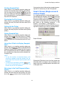
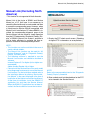
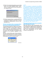
Using this Manual
Though the SSMΙΙΙ is designed for fault diagnosis
operations using an interactive user interface, there
may be times that you will need to refer to this manual to find out more about using more complex procedures. When performing actual fault diagnostic
work, you should also refer to the Service Manual.
Click the title in contents to go to the relevant page.
1
Contents
Creating a Mode File ................................46
Reading a Mode File for Sampling ...........48
Trigger ...........................................................50
Getting Ready ...........................................50
Configuring Trigger of input data
Settings .....................................................52
Configuring a Manual Trigger ...................54
Two Cursor Analysis .....................................56
Cursor Numerical Value Information
between Two Points .................................56
Data Cut-and-Save ...................................58
Converting Sampled Data to CSV .................61
How to Convert to CSV from Menu ..........61
How to Convert to CSV with Save Icon or
Save Button ..............................................62
In the Case of Too Many Sampled Data ...63
Saving Displayed Data ..................................66
How to Save .............................................66
Saved Data Display .......................................67
Display Screen Operations .......................68
Multiple display of saved data ...................68
Diagnostic Codes Display .............................71
Manual Link (Excluding North America) ........74
Clearing Memory ...........................................76
System Operation Check Mode ....................78
Actuator ON/OFF Operation .....................79
Fuel Pump Control ....................................79
Fixed Idle Ignition Timing ..........................80
Idle Speed Control ....................................80
Injector Control .........................................80
EGR Valve Control ...................................80
Dealer Check Mode Procedure .....................81
OBD System ..................................................85
Function Check Sequence ............................89
ABS Function Check Mode .......................90
VDC Function Check Mode ......................90
Steering Angle Sensor Neutral and Lateral
G Sensor Zero Setting Mode ....................90
Fault Data Display .........................................91
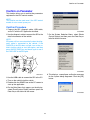
Selection of Parameter ..................................93
Using this Manual ....................................... 1
Introduction ..................................................... 5
List of Abbreviation ......................................... 6
Before Starting Diagnosis ............................... 9
Handling Precautions ................................. 9
SSMΙΙΙ Features ......................................... 9
Switching the SDI Mode ................................ 11
SDI Mode Types ....................................... 11
Switching a Mode ..................................... 11
Display Software Version Information ........... 12
PC Application Version Information .......... 12
CF Application Version Information .......... 12
Starting Up the System ................................. 13
Main Menu Items ...................................... 13
Quitting the System .................................. 14
Wireless LAN Communication ...................... 16
Caution items ........................................... 16
Parts required for wireless LAN
communication ......................................... 17
Outline of the wireless LAN connection
procedure ................................................. 17
Wireless LAN setting on the PC side ....... 17
Wireless LAN setting on the SDI side ...... 24
Switching to wireless LAN connection ...... 25
Switching to USB connection ................... 26
When using equipment already set for
wireless LAN ............................................ 27
List of terms related to Wireless LAN
communication ......................................... 28
Communication Messages ............................ 29
All Systems Diagnosis .................................. 30
Each System Check ...................................... 31
Current Data Display and Save .................... 33
Digital Data Screen Operations ................ 34
Graph 1 Screen ........................................ 38
Graph 2 Screen (Single-screen 8-channel
Graph) ...................................................... 44
Setting All Clear Function ......................... 45
Functions for Initializing Toolbars ............. 45
Sampling Item Memory ................................. 46
2
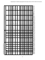
Keyless access with push button start
system: Correspondence table at the
time of parts failure .................................145
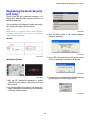
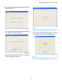
Registering the Audio Security (U.K Only) ..148
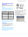
Learning and inspection mode related
to AT ............................................................151
Getting Ready .........................................151
AT learning mode ...................................152
AT air bleeding mode ..............................155
Learning, inspection, and registration mode
related to diesel engines (Excluding North
America) ......................................................156
Diesel compulsory learning mode ...........156
Registering the Injector Code .................158
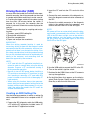
Driving Recorder (SDR) ..............................165
Creating an SDR Setting File ..................165
Saving SDR Data to CF Card .................167
Saving SDR Data to PC ..........................168
Opening and analyzing saved data ........171
Trigger Function ......................................171
ECM Analog Simultaneous Measurement
(SDR) ..........................................................175
Creating an SDR Setting File ..................175
Saving SDR Data to CF Card .................178
Saving SDR Data to PC ..........................179
Opening and analyzing saved data ........179
Remote Box .................................................180
Handling Precautions ..............................180
Names of Parts .......................................180
Connecting to the SDI .............................180
Remote Box Functions ...........................180
Sampling of G Sensor Analog Output .....181
Guideline for reprogramming procedure for
SSMΙΙΙ .........................................................183
Notes on doing ECM reprogramming .....183
ECM reprogramming ..............................183
Setting Screen Font, Display Unit and Display
Language ....................................................186
Changing the Screen Font ......................186
Changing the Display Units ....................186
Changing the Display Language .............187
Analog Sampling .........................................188
Handling Precautions ..............................188
Pulse/Analog Kit Contents ......................188
Registration Procedure ............................. 93
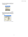
Confirm on Parameter ................................... 95
Confirm Procedure ................................... 95
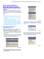
Body Integrated Module Destination
Market Registry (Excluding North America
and Japan) .................................................... 97
Confirmation of Vehicle Destination
(Part 1) ..................................................... 97
Confirmation of Vehicle Destination
(Part 2) ..................................................... 98
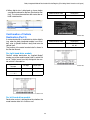
Registration Steps for Registering Vehicle
Destination ............................................... 99
Body Integrated Module Function Check .... 100
Body Integrated Module Function Setting
(Integ.Unit Customizing) ............................. 102
Display the List of Function Setting (Integ.
Unit Customizing) ........................................ 104
How to Display the List ........................... 104
Displaying Saved Files ........................... 105
Printing the Data ..................................... 106
Impact Sensor ............................................. 107
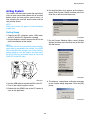
Registering the Transmitter ......................... 109
Keyless Entry Control Module Function
Setting (Keyless unit Customizing) ............. 111
Registering the Tire Pressure Monitoring
System Transmitter (ID) .............................. 113
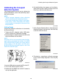
Calibrating the Occupant Detection
System ........................................................ 116
Airbag System ............................................. 120
CAN System Fault Location ........................ 122
Registering the Immobilizer (Not Equipped
with Keyless Access with Push Button Start
System) ....................................................... 123
Registering the Immobilizer (Equipped with
the Keyless Access with Push Button Start
System) ....................................................... 128
Registering the Smart Immobilizer ......... 129
Registering the Smart ECM .................... 133
Registering the Engine ECM .................. 135
Readout the Number of Mobile Key
(Access Key) Registration ...................... 138
Delete the Mobile Key (Access Key)
ID ............................................................ 139
Registering the Remote Control Engine
Starter ..................................................... 141
3
Registering the Immobilizer (Equipped with
the Keyless Access with Push Button Start
System) ...................................................228
Registering the Smart Immobilizer ..........229
Registering the Smart ECM ....................232
Registering the Engine ECM ..................234
Readout the Number of Mobile Key
(Access Key) Registration ......................236
Delete the Mobile Key (Access Key)
ID ............................................................237
Registering the Remote Control Engine
Starter .....................................................239
Configuring SDI Functions ......................240
Performing SDI Self-diagnosis ................243
SDI System Menu .......................................248
Getting Ready (Starting Up the SDI in the
System Mode) .........................................248
SELF CHECK (SDI Self-check) ..............248
VERSION CHECK ..................................253
FUNCTION SETUP (SDI Function
Setup) .....................................................253
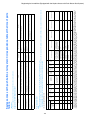
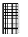
List of Contents on Displayed Data .............255
Engine .....................................................255
Transmission ..........................................271
Body Integrated Unit ...............................281
Communication Error Code List ..................300
ECM Reprogramming Error Code List ........302
ECM Reprogramming Error Code List
(PC Display) ............................................302
ECM Reprogramming Error Code List
(NSM LCD Display) ................................316
SSMΙΙΙ revision history ................................318
List of Part Numbers ....................................324
Getting Ready for Sampling ................... 188
Starting a Sampling Operation ............... 189
Configuring Analog Sampling Settings ... 190
Trigger Function ..................................... 193
Changing the Range while Using Auto
Range ..................................................... 195
Initialize Item Settings ............................ 196
Other Operations .................................... 196
ECM Analog Simultaneous Measurement .. 197
Starting ECM Analog Simultaneous
Measurement ......................................... 197
Stopping ECM Analog Simultaneous
Measurement ......................................... 200
Trigger Function ..................................... 200
Data Select Screen ................................ 201
Setting All Clear Function ....................... 201
Other Operations .................................... 202
Roughness Monitor ..................................... 203
Sampling with Simple Roughness
Monitor ................................................... 203
Sampling with High-Grade Roughness
Monitor ................................................... 205
Changing Graph Range ......................... 209
Saving Sampled Data ............................. 209
Saved Data Display ................................ 210
SDI Stand-alone Diagnosis ......................... 212
Getting Ready (Starting Up the SDI in
Stand-alone Mode) ................................. 212
All Systems Diagnosis ............................ 212
Diagnostic Codes Check on Each
System ................................................... 213
Data Display ........................................... 214
Saving Sampled Data ............................. 216
Save data stored in a
CF card to a PC. ..................................... 216
Clearing Memory .................................... 220
Body Integrated Module Function Setting
(ECM Customizing) ................................ 221
Impact Sensor ........................................ 222
Registering the Tire Pressure Monitoring
System Transmitter (ID) ......................... 223
Registering the Immobilizer (Not Equipped
with Keyless Access with Push Button Start
System.) ................................................. 225
4
Introduction
Introduction
The SSMΙΙΙ is a powerful fault diagnosis device that
has been developed using the latest advanced
technology. Used in combination with a PC, it provides a tool for quick and efficient analysis of vehicle
faults.
Application software running on a PC provides an
interactive user interface for very simple operation.
High-speed communication with the engine control
system and transmission control system help to
make checking of various phenomena faster than
ever before.
Be sure to carefully read this manual in combination
with the Service Manual to develop fault diagnostic
skills by using SSMΙΙΙ functions to their fullest.
Note that the illustrations and display screens
shown in this manual may differ from those of the
actual SSMΙΙΙ due to specification modifications.
Microsoft, Windows 2000, Windows XP, Internet Explorer are either registered
trademarks of Microsoft Corporation.
Intel, Pentium M is a registered trademark of Intel Corporation.
Adobe Acrobat Reader is a registered trademark of Adobe Systems Incorporated.
EFI (Electronic Fuel Injection) is a trademark of TOYOTA MOTOR CORPORATION.
is a registered trademark of FUJI HEAVY INDUSTRIES Ltd.
© copyright 2004- FUJI HEAVY INDUSTRIES Ltd.
5
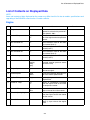
List of Abbreviation
List of Abbreviation
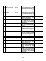
Abbreviation
Spell-out
A/C
Air Conditioner
A/F
Air/Fuel ratio
ABS
Anti-lock Brake System
AC
Alternating Current
ACC
Accessory
AET
AT Engine Torque request
ASSY
Assembly
AT
Automatic Transmission
ATF
Automatic Transmission Fluid
AWD
All Wheel Drive
BIU
Body Integrated Unit
BMP
Bit MaP
CAM
Camshaft
CAN
Controller Area Network
CD
Compact Disk
CD-ROM
Compact Disk Read Only Memory
CF
Compact Flash
CID
Calibration Identification
CNG
Compressed Natural Gas
COM
Common
CPC
Canister Purge Control solenoid valve
CR
Crankshaft
CSV
Comma Separated Values
DC
Direct Current
DCCD
Drivers Control Center Differential
DRL
Daytime Running Lights
D-sub
D subminiature
DTC
Diagnostic Trouble Code
EAM
Engine AT Masking flag
ECM
Electronic Control Module
EGR
Exhaust Gas Recirculation
ETC
Electronic Throttle Control system
FWD
Front Wheel Drive
6
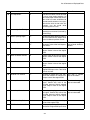
List of Abbreviation
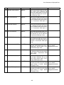
Abbreviation
Spell-out
IC
Integrated Circuit
ID
Identification
IG
Ignition
ISC
Idle Speed Control
LAN
Local Area Network
LCD
Liquid Crystal Display
LED
Light Emitting Diode
LH
Left Hand
LSD
Limited Slip Differential
MIL
Malfunction Indication Lamp
MT
Manual Transmission
NSM
New Select Monitor
OBD
On Board Diagnosis
OCV
Oil flow Control solenoid Valve
OS
Operating System
OSV
Oil Switching solenoid Valve
P/W
Power Window
PAK
Pack
Pass
Passing
PC
Personal Computer
PTC
Positive Temperature Coefficient
PV
Power system supply Voltage *1
RAM
Random Access Memory
RH
Right Hand
ROM
Read Only Memory
RTC
Real Time Clock
SAE
Society of Automotive Engineers
SDI
SUBARU Diagnostic Interface
SDR
SUBARU Driving Recorder
SI
International System of Units
SSMΙΙΙ
SUBARU Select Monitor ΙΙΙ
SW
Switch
TCM
Transmission Control Module
TCS
Traction Contorol System
TGV
Tumble Generator Valve
7
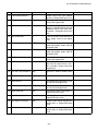
List of Abbreviation
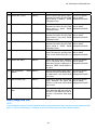
Abbreviation
Spell-out
TPMS
Tire Pressure Monitoring System
Tr
Transistor
USB
Universal Serial Bus
VDC
Vehicle Dynamics Control
VVL
Variable Valve Lift
VVT
Variable Valve Timing
*1: There are two power supplies, “Power system supply voltage” actuates an actuator and “Sensor system
supply voltage” activates a sensor.
8
Before Starting Diagnosis
Before Starting Diagnosis
2) Powerful Application Software
Application software running on a PC provides an
interactive user interface for very simple operation. A hierarchical menu system simplifies routine operations, even for novice users.
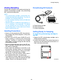
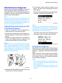
Handling Precautions
• The SDI is a precision measuring instrument.
Prevent water, oil, grease or other substance
from getting on the SDI.
• Never try to take the SDI or its bundled items
apart.
• Never disconnect the diagnosis cable from the
vehicle data link connector or the SDI while the
system is ON. Doing so can damage the SDI.
• Never insert or remove a CF card while SDI power is turned on.
• Always insert the bundled dummy card in the
card slot when not using a CF card.
• Take care to avoid damage to the LCD of the SDI.
Should the LCD panel ever become cracked and
start leaking liquid, do not touch the liquid. If you
get the liquid on your skin, immediately flush the
exposed area with large volumes of water.
Should you experience any skin abnormalities,
consult with a skin specialist immediately.
• Whenever using the SSMΙΙΙ for fault diagnosis
while the vehicle is in motion, never allow the
driver to operate the SSMΙΙΙ or SDI.
3) Communication Functions
The SDI communicates directly with the vehicle’s
ECMs, while transfer between the SDI and PC is
performed over a high-speed USB 1.1 connection. The SDI is also equipped with card slots,
creating hardware architecture that can support
both wired and wireless LAN communication between the SDI and PC.
4) Multilingual Support
The SSMΙΙΙ supports five languages: English,
French, German, Spanish, and Japanese.
The language switches automatically in accordance with the language of the operating system
running on the connected PC, eliminating operator confusion.
5) Data Sampling
Data sampling is performed for all items, which
eliminates the chance of the operator forgetting to
obtain required data. After all data is sampled and
stored, specific data items can be recalled for
analysis as required. Communication speed is
fast enough to support normal diagnosis without
any problem. This system can be configured to
select measurement items during sampling,
which switches the communication protocol for
high-speed data communication.
Switching is performed at intervals of some tens
of ms, so phenomena can be reliably recorded,
even if they have a very short life. (This capability
is available with engines and transmission control
systems that employ the latest communication
protocol.)
SSMΙΙΙ Features
The SSMΙΙΙ is a fault diagnosis device that provides
a standard means of automotive fault diagnosis. It
communicates with the various system control modules equipped in a vehicle to monitor control module
input/output data, and to allow checking and deletion of diagnostic codes generated by the control
module. It also provides means to reset control
module learning values and other control parameters, and to force operation of engine control system
actuators.
1) Bi-directional Communication with Vehicle Electronic Control Modules (ECM)
The SSMΙΙΙ makes it possible to perform bi-directional communication between a PC and each of
a vehicle’s on-board ECMs via a SUBARU Diagnostic Interface (SDI). This makes it possible to
monitor ECM data, check ECM diagnostic codes,
and force operation of actuators.
6) Digital Data Display
Data is displayed on a PC monitor making it easier to view.
Though the number of items that can be displayed depends on the size of the PC monitor
screen and the font size, typically more than 25
items can be displayed simultaneously.
9
Before Starting Diagnosis
7) Graph Data Display
Data displayed on PC monitor in color greatly facilitates interpretation and analysis of diagnostic
phenomena. Graph line colors can be specified
as desired, which makes it possible to display
graphs that suit individual preferences and
needs.
8) Diagnosis Cable
A standard SAE J1962 connector is used on the
end of the cable that connects to the vehicle.
The end that connects to the SDI is a highly durable D-Sub 44-pin connector.
The length of the cable is a convenient 2.3 m (7.5
ft). Reprogramming work can also be performed
using this cable.
9) USB cable
Since communication between the PC and SDI is
performed using USB 1.1 protocol, a USB cable
is used to connect the PC and SDI.
The cable is 3 m (10 ft) long, which allows computer analysis even when the PC is located at a
considerable distance from the vehicle.
10)SDI Cushioning Rubber
Cushioning rubber attached to SDI absorbs
shock and protects the interface from damage if it
is dropped.
10
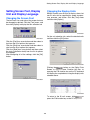
Switching the SDI Mode
Switching the SDI Mode
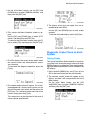
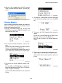
Stand-alone Mode
To enter the Stand-alone Mode, hold down both the
[MENU] key and the [C] key of the SDI for at least
two seconds, during the Driving Recorder Mode, or
at the initial screen of the PC Application Mode.
Exiting the Stand-alone Mode automatically enters
the Driving Recorder Mode.
SDI Mode Types
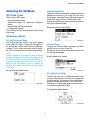
There are four SDI modes.
• Driving Recorder Mode
• Stand-alone Mode (CF Application Diagnosis
Mode)
• System Mode (SDI System Mode)
• PC Application Mode
The following sections provide details about using
each mode.
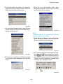
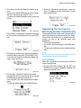
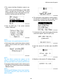
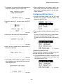
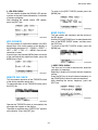
Stand-alone Mode Initial Screen
Switching a Mode
Driving Recorder Mode
SMU-00513
The Driving Recorder Mode is the initial default
mode when SDI power is turned on. Exiting any of
the other modes always enters the Driving Recorder Mode. That is, unless any other mode is operated, the SDI maintains the Driving Recorder Mode.
System Mode
To enter the System Mode, hold down the SDI’s
[MENU] key as you turn on the SDI.
Exiting the System Mode automatically enters the
Driving Recorder Mode.
NOTE:
A special setting file is required only when using the
Driving Recorder Mode. If there is no setting file on
the CF card when the Driving Recorder Mode is entered, the message “No Setting File in CF Card” appears on the SDI display. Lack of a setting file
presents no problem if the Driving Recorder Mode
is not used.
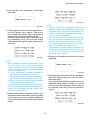
System Mode Initial Screen
Driving Recorder Mode Screen
SMU-00322
PC Application Mode
The SDI will enter the PC Application Mode automatically whenever you start up the PC application
on the computer and execute various diagnostics,
sampling or registration while in any other mode.
Exiting the PC Application Mode automatically enters the Driving Recorder Mode.
SMU-00548
PC Application Mode Screen
SMU-00519
11
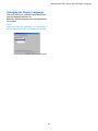
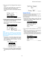
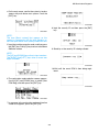
Display Software Version Information
Display Software Version
Information
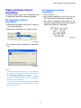
CF Application Version
Information
To display software version of PC application and
CF application, perform the following procedure.
1. Turn on the SDI.
2. Press the both [MENU] key and [C] key on the
SDI at the same time more than two seconds.
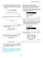
PC Application Version
Information
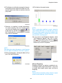
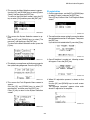
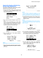
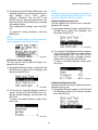
3. The version information shown below is displayed few seconds before Initial Menu screen of
Stand-alone Diagnosis is displayed.
1. Double-click the SSMΙΙΙ icon on the PC screen to
start up the application.
2. Select “About application” from “Help” in menu.
SMU-00812
SMU-00810
3. This displays version information as shown below.
SMU-00811
NOTE:
• To confirm version information, it is not necessary
to connect a PC to vehicle. The version information can be displayed on a PC alone.
• In High-Grade Roughness Monitor sampling
screen, the version information of Roughness
Monitor will be displayed.
• To confirm the functions supported in displayed
version (for software currently installed), see “SSMΙΙΙ revision history”.
12
Starting Up the System
Starting Up the System
With the SSMΙΙΙ, the PC application communicates
via the SDI with the control modules for which SSMΙΙΙ diagnosis is supported. In order to enable normal communication, start up the SSMΙΙΙ using the
procedure described below.
NOTE:
• Power from the vehicle’s battery is supplied to the
SDI via the fault diagnostic cable.
• If you use the SSMΙΙΙ when the vehicle’s battery
is low, then a communication error may occur
when the engine is started. This is caused by a
drop in the voltage as a large current flows to the
starter motor, because the SDI stops operating. If
this happens do the following.
1. To continue testing for faults after starting the
engine, after starting the engine press the
[PWR] key on the SDI to turn on the power,
then restart the SSMΙΙΙ operation.
2. To do fault diagnosis while the engine is running, charge the battery completely before doing the fault diagnosis.
• If the PC has more than one USB port, the PC
USB port where the SDI is connected when you
install the USB driver will become the special SSMΙΙΙ port. Whenever using the SSMΙΙΙ, always
connect the USB cable to the special SSMΙΙΙ port
only.
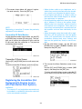
SMU-00113
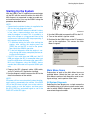
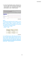
3. Use the USB cable to connect the SDI to the PC.
4. Turn on the vehicle’s ignition switch.
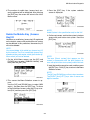
5. Double-click the SSMΙΙΙ icon on the PC screen to
start up the application. This causes the Main
Menu to appear.
SMU-00600
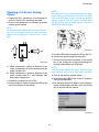
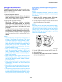
1. Prepare the SDI, diagnosis cable, USB cable,
and a PC with the PC application installed.
Main Menu Items
Explanations of each of the Main Menu items are
provided below. Select the item you want on the
Main Menu to perform fault diagnostic word, to configure settings, and to perform other tasks.
2. Use the diagnosis cable to connect the SDI to the
data link connector of the vehicle.
NOTE:
SDI power will turn on automatically when the diagnosis cable is connected to the vehicle. If the PWR
LED of the SDI does not light, turn on the vehicle’s
ignition switch or start the engine, and then press
the SDI [PWR] key and check again to see if the
PWR LED of the SDI lights.
All System Diagnosis
Selecting this item displays on a single screen the
fault detect status of all control system control modules for which SSMΙΙΙ diagnosis is supported, and
memorized diagnostic codes.
13
Starting Up the System
Each System Check
• SDI power will turn off automatically if you leave
the diagnosis cable connected to the SDI and do
not perform any operation on the PC for a certain
period. This is indicated when the PWR LED of
the SDI goes out.
If this happens, press the SDI [PWR] key to turn
it back on again.
Selecting this item makes it possible to select a particular system from among the control systems for
which SSMΙΙΙ diagnosis is supported, and perform
fault diagnosis.
This item can be used to view input/output data of
the system control modules that perform fault diagnosis, memorized diagnostic codes, and other data
on the PC display.
This menu item is also used after repair work is
complete to delete diagnostic codes, to configure
control module settings, etc.
Quitting the System
1. On the Main Menu, select [Quit] and then press
the Enter key or left-click with the mouse.
You can also quit the system by selecting [Quit]
on the [File] menu, by clicking the
button
on the function Key Bar, or by pressing the F12
function key on the PC keyboard.
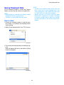
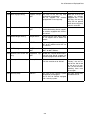
Saved Data Display
This item can be used to save various data sampled
during fault diagnosis operations, and to load data
for viewing after work is complete.
Immobilizer
This item performs immobilizer registration.
Reprogram
This item performs reprogramming of the control
module.
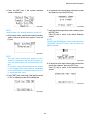
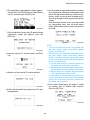
Read CF application measurement data
SMU-00568
This item performs reading stand alone measurement data saved in a CF card to hard disk of your
PC.
2. Confirm that the PC application is no longer running, and turn off the vehicle ignition key.
Convert/Save measurement data on
driving recorder
3. Disconnect the diagnosis cable from the vehicle
data link connector. The SDI is turned off when
the diagnosis cable is disconnected.
Loads data sampled on the driving recorder to the
PC from the CF card, and converts and saves that
data.
NOTE:
The SDI can also be turned off by holding down
both the [MENU] key and the [DOWN] key of the
SDI for at least two seconds.
Oscilloscope
After attaching the optional pulse/analog cartridge
to SDI, connect the pulse/analog box to the SDI and
using pulse/analog probe to perform analog sampling.
4. Disconnect the diagnosis cable and the USB cable from the PC and SDI.
NOTE:
The PC application settings listed below are remembered whenever the system is exited. These
settings are automatically restored the next time the
PC application is started up.
NOTE:
• A message may appear during system startup instructing you to update the PC application. If it
does, install the newest version of the PC application as soon as possible.
• Display order of Digital Data Screen and Graph
Screen items
• Display cell width settings
14
Starting Up the System
•
•
•
•
•
•
•
Data select function setting items
Graph Screen range settings
Graph Screen graph line colors and thicknesses
Display language
Display unit settings
Display font settings
Print settings
15
Wireless LAN Communication
Wireless LAN Communication
• As wireless LAN communication is communication
by radio waves, the communication status deteriorates when the communication distance between
PC and SDI increases. The confirmation status
can be confirmed with the “NET” lamp of the PC
wireless LAN card or the “Number of samples” of
the sampling status bar. If the communication status has become bad, reduce the distance between
PC and SDI to improve the communication status.
The system configuration is so that data measuring is possible even when the communication status has deteriorated and the sampling number is
not displayed continuously, but when the communication status deteriorates extremely, communication errors may occur. (However, data display is
not possible when the communication has been
cut completely.)
The normal communication method (connection
method) between PC and SDI is by USB cable, but
when a wireless LAN card is used, wireless LAN
communication without a USB cable is possible.
This chapter explains the setting method for wireless LAN communication when the following environment is used.
<Use environment>
OS:Windows XP or Windows 2000
Wireless LAN: PC built-in or external type (PC card
slot)
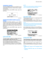
Caution items
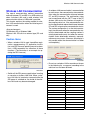
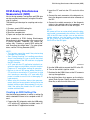
• When a wireless LAN is used, immobilizer registration, reprogramming, CF application installation, and SDI firmware updating cannot be done.
Use a USB connection for execution of these
functions. (The illustration is an example for updating the SDI firmware.)
SMU-00982
• Do not use a wireless LAN in countries not shown
in the following list, as approval according to the
radio law has not been obtained.
SMU-00993
Australia
Japan
• Switch off the SDI power supply before inserting
or removing a wireless LAN card. When a wireless LAN card is inserted or removed while the
SDI power is switched on, the inside of the wireless LAN card may become damaged.
Bulgaria
Malta
Canada
Netherlands
Chile
New Zealand
China
Norway
Cyprus
Poland
Czech
Portugal
France
Saudi Arabia
Germany
Singapore
Greece
Spain
Guam
Sweden
Hawaii
Switzerland
Iceland
Taiwan
Ireland
Turkey
Israel
U. K.
Italy
USA
16
Wireless LAN Communication
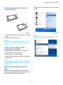
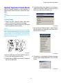
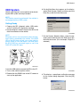
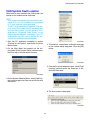
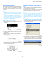
Parts required for wireless LAN
communication
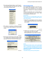
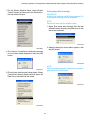
1. Click “Start” on the taskbar and select “Control
Panel”.
A
B
SMU-01023
SMU-00983
A: PC with built-in wireless LAN or external wireless
LAN
B: Wireless LAN card for SDI
NOTE:
Depending on the PC display settings, click “Start”
and select “Control Panel” from “Settings”.
NOTE:
A CD-ROM is enclosed with the wireless LAN card
for SDI, but it is not used. SDI requires no driver installation.
Outline of the wireless LAN
connection procedure
Explanations are provided only for Windows XP.
1. Install a wireless LAN for the PC.
2. Set the SDI side to wireless LAN.
3. Switch the SDI connection method from USB to
wireless LAN.
SMU-00984
NOTE:
In case of Windows 2000, use your wireless LAN
utility and perform setting for wireless LAN communication.
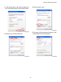
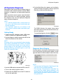
Wireless LAN setting on the PC
side
Explanations are provided only for Windows XP.
In case of an external type, connect the wireless
LAN card and install the driver on the PC.
17
Wireless LAN Communication
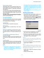
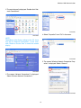
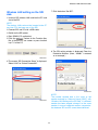
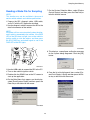
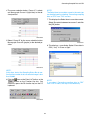
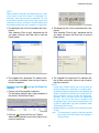
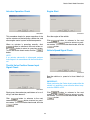
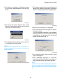
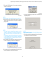
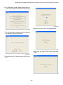
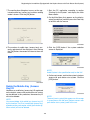
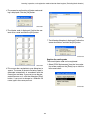
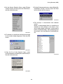
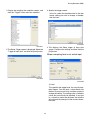
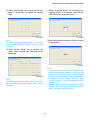
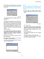
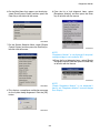
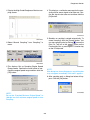
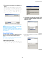
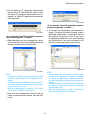
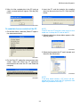
2. The control panel is displayed. Double-click “Network Connections”.
SMU-00987
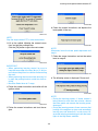
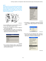
4. Select “Properties” from “File” in the menu.
SMU-00985
NOTE:
Depending on the display settings of the PC, there
may be no “Network Connections”. In this case,
click “Switch to Classic View” to switch the screen
display.
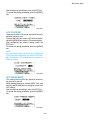
SMU-00988
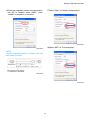
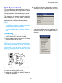
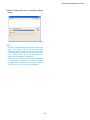
5. The screen “Wireless Network Connection Properties” is displayed. Select “General”.
SMU-00986
3. The screen “Network Connections” is displayed.
Select “Wireless Network Connections”.
SMU-00989
18
Wireless LAN Communication
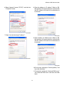
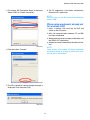
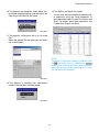
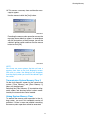
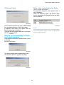
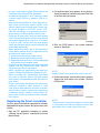
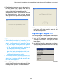
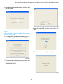
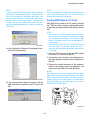
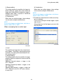
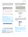
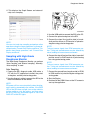
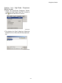
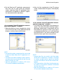
6. Select “Internet Protocol (TCP/IP)” and click the
“Properties” button.
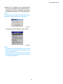
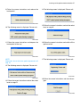
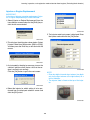
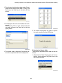
8. Enter the address to “IP address”. Refer to “SSMΙΙΙ wireless LAN communication” enclosed with
the SDI wireless LAN card for the characters to
be entered.
SMU-00990
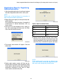
7. Check “Use the following IP address:”.
SMU-00992
9. Enter numbers for “Subnet mask”. Refer to “SSMΙΙΙ wireless LAN communication” enclosed with
the SDI wireless LAN card for the characters to
be entered.
SMU-00991
SMU-00994
10.Do not enter anything for “Default gateway” and
leave the field blank.
11.Do not enter anything for “Preferred DNS server”
and “Alternate DNS server” and leave the fields
blank.
19
Wireless LAN Communication
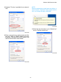
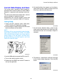
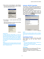
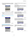
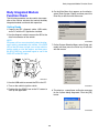
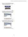
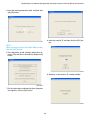
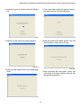
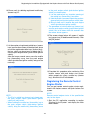
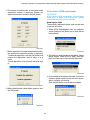
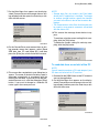
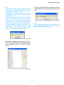
12. After confirmation of the entered setting contents, click the button [OK] and close the window.
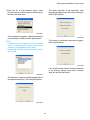
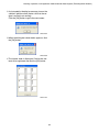
14.Click the button “Add…”.
SMU-00997
SMU-00995
15.The screen “Wireless Network Properties” is displayed. Select the tab “Association”.
13.Select the tab “Wireless Networks”.
SMU-00996
SMU-00998
20
Wireless LAN Communication
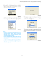
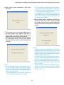
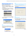
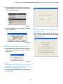
16.Enter the production number of the communication SDI in “Network Name (SSID)”. (Here,
“100001” is entered as an example.)
17.Select “Open” for “Network Authentication”.
SMU-01001
18.Select “WEP” for ”Data encryption”.
SMU-00999
NOTE:
The SDI Production Number is shown on the seal
on the side of the SDI.
SMU-01000
SMU-01002
21
Wireless LAN Communication
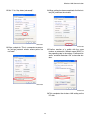
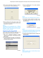
19.Uncheck “The key is provided for me automatically”.
NOTE:
Enter the network keys using lower case letters. In
case of input in “CapsLock” status (upper case letters), an warning message is displayed.
SMU-01005
21.Enter the same characters as for “Network key”
also for “Comfirm network key”.
SMU-01003
20.Enter an encryption key (alphanumeric) for “Network key”. Refer to “SSMΙΙΙ wireless LAN communication” enclosed with the SDI wireless LAN
card for the characters to be entered.
SMU-01006
SMU-01004
22
Wireless LAN Communication
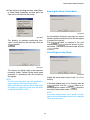
22.Set “1” for “Key index (advanced)”.
24.When setting has been completed, click the button [OK] and close the window.
SMU-01007
SMU-01009
23.Enter a check for “This is a computer-to-computer [ad hoc] network: wirelss access points are
not used”.
25.Confirm creation of a profile with the same
number as entered for “Network name (SSID)” in
the preceding step in the column “Preferred networks” and click the button “OK” to close the window.
SMU-01008
SMU-01010
26.This completes the wireless LAN setting on the
PC side.
23
Wireless LAN Communication
Wireless LAN setting on the SDI
side
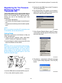
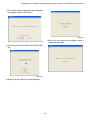
7. Click the button “Set SDI”.
1. Insert an SDI wireless LAN card into the CF card
slot of the SDI.
NOTE:
The wireless LAN card must be inserted to the CF
card slot CF2, the lower one, of the SDI.
2. Connect SDI and PC with a USB cable.
3. Switch on the SDI power.
4. Start SSMΙΙΙ (PC application).
5. Click the
botton on the Function Key
Bar of the main menu screen or press function
key F11 of the PC.
SMU-01013
8. The SDI setting window is displayed. Enter the
Production Number. (Here, “100001” is entered
as an example.)
SMU-01011
6. The screen “SDI Connection Setup” is displayed.
Select “LAN” for “Select Connection”.
SMU-01014
NOTE:
The number entered here is the same as the
number entered for “Network Name (SSID)” with
“Wireless LAN Setting on the PC Side”. If a different
number has been entered, change it to the same
number. In case of a different number, communication between SDI and PC cannot be established.
SMU-01012
24
Wireless LAN Communication
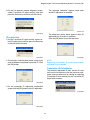
3. Click the
button on the Function Key
Bar of the main menu screen or press function
key F11 of the PC.
9. Confirm the entered number and click the button
[OK].
SMU-01011
4. The screen “SDI Connection Setup” is displayed.
Select “LAN” for “Select Connection”.
SMU-01015
10.The setting completion message is displayed.
Click the button [OK].
SMU-01012
SMU-01016
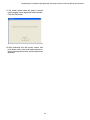
5. Click the button “SDI Search”.
11.Restart the SDI.
Switching to wireless LAN
connection
1. Wait until communication between PC and SDI
has been established.
2. When communication has been established, start
the SSMΙΙΙ (PC application).
SMU-01017
25
Wireless LAN Communication
7. The SDI connection setting change message is
displayed. Click the button [OK].
NOTE:
In some cases, depending on Windows Security
setup, the screen shown below appears. If so, click
“Unblock”.
SMU-01019
8. The PC application is shut down automatically.
Restart the PC application.
NOTE:
• From this time on, the connection method for PC
and SDI is wireless LAN.
• The present connection method for PC and SDI
is shown on the title bar at the left top of the
screen.
SMU-01038
6. The SDIs which can be connected are shown in
“List of SDI”. Enter a check for the SDI to be connected to and click the button “Connect”.
SMU-01020
Switching to USB connection
1. Start SSMΙΙΙ (PC application).
2. Click the
button on the Function Key
Bar of the main menu screen or press function
key F11 of the PC.
SMU-01018
SMU-01011
NOTE:
At this time, restart the PC if no SDIs possible for
connection are displayed.
26
Wireless LAN Communication
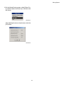
3. The screen “SDI Connection Setup” is displayed.
Select “USB” for “Select Connection”.
6. The PC application is shut down automatically.
Restart the PC application.
NOTE:
From this time on, the SDI connection method becomes “USB”.
When using equipment already set
for wireless LAN
1. Insert a wireless LAN card into the SDI and
switch on the SDI power.
2. Wait until communication between PC and SDI
has been established.
3. When communication has been established, start
the SSMΙΙΙ (PC application).
4. Afterwards, select and execute the desired function.
SMU-01021
NOTE:
Once wireless LAN setting has been completed,
connection setting or change by clicking the function key bar is not required.
4. Click the button “Connect”.
SMU-01022
5. The SDI connection setting change message is
displayed. Click the button [OK].
SMU-01019
27
Wireless LAN Communication
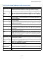
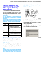
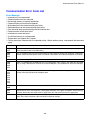
List of terms related to Wireless LAN communication
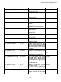
Term
Meaning
ASCII
Abbreviation of American Standard Code for Information Interchange. A general system of
specific characters allotted to recognition of characters and symbols by a computer.
DNS server
“DNS” is the abbreviation of “Domain Name System”. A system for converting a domain
name corresponding to the name of a computer on the Internet to an IP address.
IEEE
Abbreviation of Institute of Electrical and Electronic Engineers. The Institute of Electrical and
Electronic Engineers has established standards for electronic parts, communication methods, etc.
IP address
“IP” is the abbreviation of Internet Protocol. An identification number allotted to a network, a
connected computer, or communication equipment. This corresponds to the address of a
computer on the network.
LAN
The abbreviation of Local Area Network. A network for connection of computers, printers,
etc. for data exchange.
OS
The abbreviation of Operating System. This is the overall management software acting as
go-between between PC hardware and various applications for keyboard input, screen output, and other I/O functions etc.
PC card
A standardized expansion card for notebook computers.
SSID
The abbreviation of Service Set Identifier. This is something like a group name in the network, and communication is possible only when the same SSID has been registered between terminals.
TCP/IP
This is the abbreviation of Transmission Control Protocol/Internet Protocol. This is a protocol
used as standard on the Internet etc.
WEP
This is the abbreviation of Wired Equivalent Privacy. This is data encryption technology for
wireless LAN communication. For wireless LAN communication between computers, a common encryption key (like a password) is set, and the data cannot be deciphered when the
encryption keys are not the same.
Autorun
A function for automatic program start when a CD is set to the CD-ROM drive.
Gateway
This is a computer or software for connection of a computer network to another network using different media or protocols.
Subnet mask
A value defined for identification of a gigantic network like the Internet and a small network
connecting computers etc. underneath it.
Driver
Software acting as go-between for OS control of peripheral equipment with different specifications and control methods for each product.
Network key
An encryption key used with a wireless LAN.
Protocol
A protocol for communication between computers via a network.
Wireless LAN card
A communication expansion card installed in a personal computer for LAN communication
with wireless transmission and reception of data.
Wireless access point
A device relaying electric waves for connection of terminals for wireless LAN communication.
28
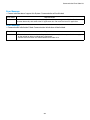
Communication Messages
Communication Messages
NOTE:
If an error occurs but an error message does not appear, restart the PC application and the SDI. When
restarting the SDI, either disconnect the diagnosis
cable from the vehicle’s data link connector, or hold
down both the [MENU] key and the [DOWN] key of
the SDI for at least two seconds to turn the SDI off,
and then confirm that the PWR LED of the SDI does
not light. Then turn on the SDI power again.
With the SSMΙΙΙ, the PC application communicates
via the SDI with the control modules for which SSMΙΙΙ diagnosis is supported.
While the PC application is performing a communication operation, various messages appear on the
display to indicate communication status. The following explains the meanings of the messages that
appear.
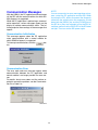
Communication Initialization
This message appears when the PC application
starts communication with a control module for
which SSMΙΙΙ diagnosis is supported.
To interrupt communication, click the
button.
SMU-00542
Communication Error
The error code and error message appear when
communication between the PC application and
control module is no longer possible for some reason.
For details about error codes and the actions required to correct the problem, see the Communication Error Code List.
SMU-00119
29
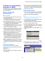
All Systems Diagnosis
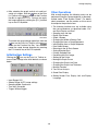
All Systems Diagnosis
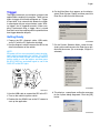
6. On the Main Menu that appears on the display,
select [All System Diagnosis] and then press the
Enter key or left-click with the mouse.
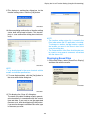
Selecting this item displays the fault detect status of
all control system control modules for which SSMΙΙΙ
diagnosis is supported, and memorized diagnostic
codes.
When a particular control system cannot be identified as the causes of a vehicle’s problem, perform
this diagnosis and use the displayed diagnostic
codes to perform diagnosis.
NOTE:
• For a vehicle equipped with a cruise control system, turn on the cruise control switch before performing inspection.
• This inspection mode may not function in the
case of certain vehicle models and vehicle specifications.
SMU-00599
The SSMΙΙΙ displays the screen shown below
when the control system and communication system are started up.
Getting Ready
To cancel the diagnosis, click the
button.
1. Prepare the SDI, diagnosis cable, USB cable,
and a PC with the PC application installed.
2. Use the diagnosis cable to connect the SDI to the
data link connector of the vehicle.
NOTE:
SDI power will turn on automatically when the diagnosis cable is connected to the vehicle. If the PWR
LED of the SDI does not light, turn on the vehicle’s
ignition switch or start the engine, and then press
the SDI [PWR] key and check again to see if the
PWR LED of the SDI lights.
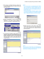
SMU-00123
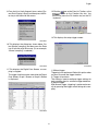
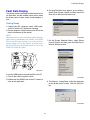
Diagnosis Result Display
A screen appears showing the fault detection status
of all of the control system control modules, and diagnostic codes that indicate details about the faults.
SMU-00124
NOTE:
• The message “No Diagnostic Code Present” indicates that no fault could be detected.
• The message “Communication Impossible” appears when the vehicle being inspected is not
equipped with the required control systems, or
when something prevents communications from
being performed.
SMU-00113
3. Use the USB cable to connect the SDI to the PC.
4. Turn on the vehicle’s ignition switch.
5. Double-click the SSMΙΙΙ icon on the PC screen to
start up the application.
30
Each System Check
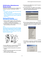
Each System Check
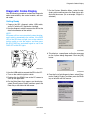
6. On the Main Menu that appears on the display,
select [Each System Check] and then press the
Enter key or left-click with the mouse.
This type of inspection allows selection of a particular system from among the control system for which
SSMΙΙΙ diagnosis is supported. Then control module input/output data, memorized diagnostic codes,
and other data can be viewed on the PC display.
This screen can also be used to delete diagnostic
codes memorized by a control module, to perform
inspections by forcing operation of actuators, to
configure control module function settings, etc.
NOTE:
• For diagnosis of the cruise control system or auto
air conditioning system, turn on the system main
switches before performing inspection.
• Some functions may not be available in the case
of certain vehicle models and vehicle specifications.
SMU-00600
7. On the System Selection Menu, select the desired system and then press the Enter key or leftclick with the mouse. (As an example, “Engine” is
selected.)
Getting Ready
1. Prepare the SDI, diagnosis cable, USB cable,
and a PC with the PC application installed.
2. Use the diagnosis cable to connect the SDI to the
data link connector of the vehicle.
NOTE:
SDI power will turn on automatically when the diagnosis cable is connected to the vehicle. If the PWR
LED of the SDI does not light, turn on the vehicle’s
ignition switch or start the engine, and then press
the SDI [PWR] key and check again to see if the
PWR LED of the SDI lights.
SMU-00665
SMU-00113
3. Use the USB cable to connect the SDI to the PC.
4. Turn on the vehicle’s ignition switch.
5. Double-click the SSMΙΙΙ icon on the PC screen to
start up the application.
31
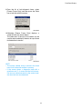
Each System Check
8. When the PC application starts communication
with the control module of the selected system, a
compliance verification message for the system
being diagnosed appears. Click the [OK] button.
NOTE:
The compliance verification message that appears
depends on vehicle model and specifications.
SMU-00128
This displays the fault diagnosis menu screen.
SMU-00601
NOTE:
• The contents of the fault diagnosis menu screen
depend on vehicle model and specifications, and
on the control system.
• Some inspection and adjustment items may not
be available in the case of certain vehicle models
and vehicle specifications.
32
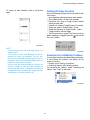
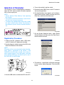
Current Data Display and Save
Current Data Display and Save
6. On the Main Menu that appears on the display,
select [Each System Check] and then press the
Enter key or left-click with the mouse.
This system allows sampling of control module input/output data of control systems for which SSMΙΙΙ
diagnosis is supported, and sampling of control data.
This data can be displayed as digital data, and can
also be switched to a graph data format.
Sampled data can also be assigned a name and
stored as a file in a particular folder in PC memory.
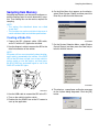
Getting Ready
1. Prepare the SDI, diagnosis cable, USB cable,
and a PC with the PC application installed.
SMU-00600
2. Use the diagnosis cable to connect the SDI to the
data link connector of the vehicle.
7. On the System Selection Menu, select the desired system and then press the Enter key or leftclick with the mouse. (As an example, “Engine” is
selected.)
NOTE:
SDI power will turn on automatically when the diagnosis cable is connected to the vehicle. If the PWR
LED of the SDI does not light, turn on the vehicle’s
ignition switch or start the engine, and then press
the SDI [PWR] key and check again to see if the
PWR LED of the SDI lights.
SMU-00113
SMU-00665
3. Use the USB cable to connect the SDI to the PC.
8. This displays a compliance verification message
for the system being diagnosed. Click the [OK]
button.
4. Turn on the vehicle’s ignition switch.
5. Double-click the SSMΙΙΙ icon on the PC screen to
start up the application.
SMU-00128
33
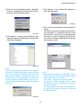
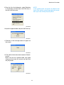
Current Data Display and Save
Digital Data Screen Operations
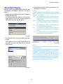
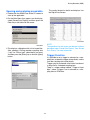
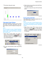
9. From the list of fault diagnosis items, select [Current Data Display & Save] and then press the Enter key or left-click with the mouse.
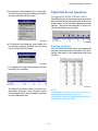
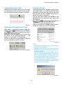
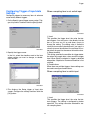
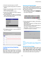
Changing the Width of Screen Cells
The widths of cells on the screen can be adjusted as
desired. Move the mouse pointer to the arrow on the
screen below so the cell width adjustment pointer
appears. Then move the pointer left or right to adjust the cell width for easy reading.
SMU-00601
SMU-00570
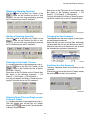
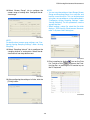
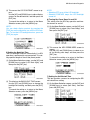
10.This displays the dialog box shown below. Select [Normal sampling] and then press the Enter
key or left-click with the mouse.
Scrolling the Screen
You can scroll the screen either by dragging the
scroll bar on the right side of the screen, or by clicking the scroll button at the upper/lower end of the
scroll bar.
SMU-00508
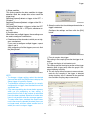
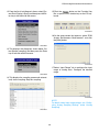
11.This displays the Digital Data Screen and automatically starts sampling.
SMU-00569
SMU-00137
The Digital Data Screen shows in real-time current values, maximum values, minimum values,
and average values of control module’s input/output data and control data.
NOTE:
Pressing the up or down arrow key on the PC keyboard will scroll the screen by one cell.
Pressing the Page Up or Page Down key on the PC
keyboard will scroll one screen.
34
Current Data Display and Save
Stopping a Sampling Operation
icon on the Data List Toolbar or the
button on the Function Key Bar to stop
sampling. You can also stop sampling by pressing
the F2 function key on the PC keyboard.
Each press of the [F3] button on the Function Key
Bar cycles in the following sequence: → [F3
Graph1] → [F3 Graph2] → [F3 Snapshot] →.
You can also display the Graph 2 Screen by pressing the F3 function key on the PC keyboard twice.
SMU-00571
SMU-00574
Click the
Starting a Sampling Operation
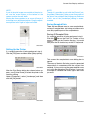
Changing the Item Sequence
Click the
The sequence that the items appear on the display
can be changed as desired.
Select the item you want to move. Next, while holding down both the Ctrl key and Shift key on the PC
keyboard, press the up or down arrow key to move
the selected item upwards or downwards.
icon on the Data List Toolbar or the
button on the Function Key Bar to start
sampling. You can also start sampling by pressing
the F2 function key on the PC keyboard.
SMU-00572
Switching to the Graph 1 Screen
SMU-00150
If a sampling operation is being performed, stop it.
Click the
icon on the Data List Toolbar or the
button on the Function Key Bar to display
the Graph 1 Screen.
Each press of the [F3] button on the Function Key
Bar cycles in the following sequence: → [F3
Graph1] → [F3 Graph2] → [F3 Snapshot] →.
You can also display the Graph 1 Screen by pressing the F3 function key on the PC keyboard.
Initializing the Item Sequence
The items’ sequence shown on the display can be
initialized.
Clicking the
icon on the Data List Toolbar makes
the items go back to their initial positions.
SMU-00728
SMU-00573
Selecting Graph 2 Screen (Single-screen
8-channel Graph)
If a sampling operation is being performed, stop it.
Click the
icon on the Data List Toolbar
twice or click the
button on the Function Key Bar
to display Graph 2 Screen.
35
Current Data Display and Save
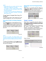
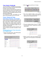
Data Select Screen
The Data Select Screen can be used to select particular data from all of the data sampled and view it.
When there is no sampling operation being performed, click the check box in front of the item you
want to view. An item is selected for viewing when
there is a check mark inside its check box. You can
also select (check) the checkbox of the highlighted
item by pressing the space bar on the PC keyboard.
SMU-00154
Returning to the All Data Screen
Click the
icon on the Data List Toolbar or the
button on the Function Key Bar to display
the All Data Screen. You can also return to the All
Data Screen by pressing the F11 function key on
the PC keyboard.
SMU-00151
Click the
icon on the Data List Toolbar or the
button on the Function Key Bar.
This will display the selected items only.
You can also display the selected items by pressing
the F6 function key on the PC keyboard.
SMU-00576
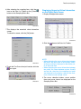
Printing Sampled Data
If a sampling operation is being performed, stop it.
Click the [File] menu and then select [Print]. You
can also print by clicking the
icon on the Data
List Toolbar, by clicking the
button on the
Function Key Bar, or by pressing the F8 function
key on the PC keyboard.
SMU-00575
NOTE:
• Displaying selected data causes data sampled up
to that point to be deleted.
• Sampling is faster when specific data items are
selected. (This applies only to engine and transmission sampling.)
• If the message dialog box shown below appears
while you are selecting data items, it means that
the limit on the number of selectable data items
has been reached. Selection of further data items
is not possible after this message appears.
To select other items, deselect the check boxes
next to the currently selected (checked) items,
and then select the new items.
SMU-00666
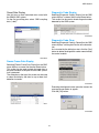
Previewing the Print Image
Print Preview lets you view the print image to confirm there are no problems before actually printing.
Click the [File] menu and then select [Print Preview].
SMU-00667
36
Current Data Display and Save
NOTE:
If part of the print image runs outside of the print area, use the arrow buttons at the bottom of the
screen to adjust the cell width.
Moving the mouse pointer to an arrow will cause it
to change to an adjustment pointer. Drag the adjustment pointer left or right to adjust cell width.
NOTE:
Though it is possible to print with the [Portrait] setting under [Orientation], doing so can cause part of
the data to run outside of the printing area. Because
of this, use of the [Landscape] setting is recommended.
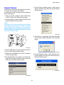
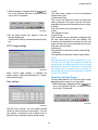
Saving Sampled Data
There are two different ways to save sampled data:
saving all sampled data and using cut-and-save to
save only specific parts of the sampled data.
Saving All Sampled Data
If a sampling operation is being performed, stop it.
Click the
icon on the Data List Toolbar, or the
button on the Function Key bar. You could
also press the F9 function key on the PC keyboard.
SMU-00162
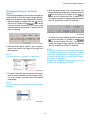
Setting Up the Printer
If a sampling operation is being performed, stop it.
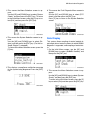
Click the [File] menu and then select [Setup printer].
SMU-00577
This causes the sampled data save dialog box to
appear.
The name of the data file being saved is generated
automatically in accordance with the current time
and date. If you want to use the generated file name
as-is, click the dialog box [Save] button. If you want
to change to a different file name, type in the name
you want.
SMU-00668
After the Print Setup dialog box shown below appears, use [Printer Name] to select the printer to be
used for printing.
Under [Orientation], select [Landscape] and then
click the [OK] button.
SMU-00164
SMU-00524
37
Current Data Display and Save
Returning to the Fault Diagnosis Menu
Screen
NOTE:
• Sample data files are saved in the Data folder
where the PC application is installed.
To change to another storage location, specify
the location you want in the Save in box of the
save data dialog box.
• The Comment box of the Save As dialog box can
be used to save general comments associated
with the data or file.
When there is no sampling operation being performed, click the
icon on the Data List Toolbar or
the
button on the Function Key Bar.
You can also return to the previous screen by pressing the F12 function key on the PC keyboard.
Saving Specific Sampled Data Using Cutand-Save
For details about how to use cut-and-save to save
specific sampled data, see “Two Cursor Analysis”.
SMU-00578
Using Non-SI Units to Display Sampled
Data
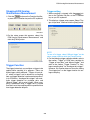
Graph 1 Screen
When there is no sampling operation being performed, click the
icon on the Data List Toolbar or
the
button on the Function Key Bar to display the Graph 1 Screen.
Each press of the [F3] button on the Function Key
Bar cycles in the following sequence: → [F3
Graph1] → [F3 Graph2] → [F3 Snapshot] →.
You can also display the Graph 1 Screen by pressing the F3 function key on the PC keyboard.
If a sampling operation is being performed, stop it.
Click the
button on the Digital Data Screen
or Graph Screen Function Key Bar, or press the F10
function key on the PC keyboard to display the sampled data using the currently selected non-SI display units.
SMU-00169
NOTE:
To use this function, the desired display units
should be selected using the window that appears
when the [Tool] menu [Option] command is executed.
SMU-00579
Graph 1 Screen
To return to SI unit display, click the
button
on the Function Key Bar or press the F10 function
key on the PC keyboard.
SMU-00580
SMU-00171
38
Current Data Display and Save
Starting a Sampling Operation
NOTE:
When operating the mouse cursor of the Graph
Screen to move the graph cursor, cursor operations
are only on the currently displayed screen. To scroll
the screen in the horizontal direction, operate the
Sampling Status Bar.
Click the
icon on the Data List Toolbar or the
button on the Function Key Bar to start
sampling. You can also start sampling by pressing
the F2 function key on the PC keyboard.
SMU-00581
Stopping a Sampling Operation
Click the
icon on the Data List Toolbar or the
button on the Function Key Bar to stop
sampling. You can also stop sampling by pressing
the F2 function key on the PC keyboard.
SMU-00693
Dragging the slider bar of the Sampling Status Bar
left or right moves the graph cursor on the Graph
Screen and scrolls the screen in the corresponding
direction.
SMU-00582
Moving the Graph Cursor
On the Graph Screen, move the mouse pointer to
your desired position and click with the mouse. The
graph cursor moves to that position. Dragging the
graph cursor also moves the graph cursor to the desired position.
The graph cursor can also be moved by operating
the left and right arrow keys on the PC. At this time,
you can also move the cursor position 10 data items
at a time by each press of either the left or right arrow key with the [Ctrl] key held down.
SMU-00185
The graph cursor also can be moved by clicking the
left or right arrow buttons at either end of the Sampling Status Bar.
SMU-00186
39
Current Data Display and Save
Sampling Status Bar Slider
Data Select Screen
Clicking within the white spaces next to the slider
bar automatically scrolls the graph screen horizontally until the slider reaches the point you clicked.
Particular graphs can be selected for display as desired. When there is no sampling operation being
performed, click the check box in front of the graph
item you want. An item is selected when there is a
check mark inside its check box.
You can also select (check) the checkbox of the
highlighted item by pressing the space bar on the
PC keyboard.
Next, click the
icon on the Data List Toolbar or
the
button on the Function Key Bar.
This will display the selected graphs only.
You can also display the selected graphs by pressing the F6 function key on the PC keyboard.
SMU-00221
Switching to the Digital Data Screen
When there is no sampling operation being performed, click the
icon on the Data List Toolbar or
the
button on the Function Key Bar twice to
display the Digital Data Screen.
Each press of the [F3] button on the Function Key
Bar cycles in the following sequence: → [F3
Graph1] → [F3 Graph2] → [F3 Snapshot] →.
You can also display the Graph Screen by pressing
the F3 function key on the PC keyboard.
SMU-00584
NOTE:
• Displaying selected data causes data sampled up
to that point to be deleted.
• Sampling is faster when specific data items are
selected. (This applies only to engine and transmission sampling.)
• If the message dialog box shown below appears
while you are selecting data items, it means that
the limit on the number of selectable data items
has been reached. Selection of further data items
is not possible after this message appears.
To select other items, deselect the check boxes
next to the currently selected (checked) items,
and then select the new items.
SMU-00583
SMU-00154
40
Current Data Display and Save
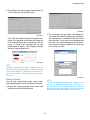
Changing the Range of the Graph
Screen
4. After the graph vertical axis and horizontal axis
range settings are configured as desired, click the
icon on the Data List Toolbar or the
button on the Function Key Bar to apply them.
You can also apply the range settings by pressing
the F11 function key on the PC keyboard.
The following procedure can be used to change the
range settings of the graph screen vertical and horizontal axes in order to make graphs easier to read.
1. While sampling is stopped, click the
icon on
the Data List Toolbar or the
button on the
Function Key Bar. You can also display the range
setting screen by pressing the F7 function key on
the PC keyboard.
SMU-00586
To cancel the range change operation, click the
icon on the Data List Toolbar or the
button on the Function Key Bar. You can also
cancel the range change operation by pressing
the F12 function key on the PC keyboard.
SMU-00585
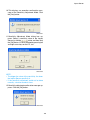
2. After the screen below appears, input a value to
specify the vertical axis range of the graph into
the range box.
NOTE:
If sampling is started while 30 sec/div or 60 sec/div
is selected with the time axis range box, sampling
results will be displayed at 10-second intervals. This
is done to prevent lag of the screen refresh operation by the PC application.
Stopping the sampling operation displays the 30
sec/div or 60 sec/div time axis screen.
NOTE:
The range box may not appear for some items.
SMU-00195
3. To specify the graph horizontal (time) axis range,
click the range selection box in the lower left corner of the screen, and then select the desired
time setting.
NOTE:
The time settings that appear depend on sampling
conditions.
SMU-00196
41
Current Data Display and Save
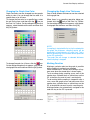
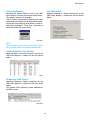
Changing the Graph Line Color
Changing the Graph Line Thickness
Graph line colors can be changed to make graphs
easier to view. You can change the line color of a
specific item or for all items.
To change the line color for a specific item, select
the cell for the item, and then click the
icon on
the Data List Toolbar. On the setting dialog box that
appears, select the desired line color and then click
the [OK] button.
One of three different thicknesses can be selected
for the graph line.
When there is no sampling operation being performed, click the
icon on the Data List Toolbar.
On the setting dialog box that appears, click the desired graph line thickness and then click [OK].
SMU-00203
NOTE:
If sampling is started while 2 pt or 3 pt is selected for
the graph line thickness, sampling results will be
displayed in a line thickness of 1 point (1 pt). This is
done to prevent lag of the screen refresh operation
by the PC application.
The graph line will change to selected thickness
when sampling is stopped.
SMU-00096
To change line color for all items, click the
icon.
On the setting dialog box that appears, click the desired graph line color and then click the [OK] button.
Marking Function
Marking a particular point on the graph is possible
while sampling is processing or stopped.
Once marked data is stored, the markings will appear even when the stored data is shown again.
To do marking during sampling, press one of the
number keys, alphabet keys or symbol keys on the
PC at the time you want to mark a certain point.
To do marking while sampling is stopped or after a
save, move the graph cursor and press one of the
number keys, alphabet keys or symbol keys on the
PC at the position you want to mark a certain point.
Marking numbers are automatically assigned in the
order the key on the PC is pressed.
SMU-00096
SMU-00461
42
Current Data Display and Save
NOTE:
• If the keys on the PC are pressed faster than the
sampling speed, the marking may not be displayed in numerical order.
• Marking is not possible with some keys.
• You can also select (check) the checkbox by
pressing the space bar on the PC keyboard.
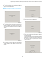
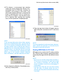
3. Click the [OK] button to close the edit screen.
Markings on the graph screen will be deleted as
soon as the edit screen is closed.
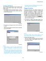
Marking Delete Function
You can delete markings.
There are two following methods to delete markings.
1) Deleting from marking edit screen
2) Deleting by PC keyboard
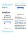
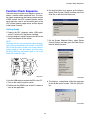
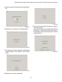
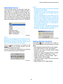
Deleting from Marking Edit Screen
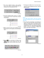
1. Display a graph on the screen and select “Edit
Markings” from “Tool” in menu.
SMU-00855
Deleting by PC Keyboard
1. Display a graph on the screen and move a cursor
to the marking to be deleted.
SMU-00853
2. Press one of the number keys, alphabet keys or
symbol keys on the PC.
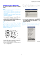
2. This displays an Edit Markings screen. Put a
check mark in the marking number to be deleted
and then click the [Confirm on Delete] button.
NOTE:
Deleting marking is not possible with some keys.
Changing the Graph Sequence
The sequence that the graphs appear on the display
can be changed as desired.
Select the graph you want to move. Next, while
holding down both the Ctrl key and Shift key on the
PC keyboard, press the up or down arrow key to
move the selected graph upwards or downwards.
Initializing the Graph Sequence
The graphs’ sequence shown on the display can be
initialized.
Clicking the
icon on the Data List Toolbar makes
the graphs go back to their initial positions.
SMU-00854
NOTE:
• Clicking the [Confirm on Delete] causes markings
on the edit screen to be deleted. However, markings on the graph are not deleted at this time.
43
Current Data Display and Save
Printing Sampled Data
You can also return to the previous screen by pressing the F12 function key on the PC keyboard.
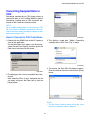
When there is no sampling operation being performed, click the [File] menu and then select [Print].
You can also print by clicking the
icon on the
Data List Toolbar, by clicking the
button on
the Function Key Bar, or by pressing the F8 function
key on the PC keyboard.
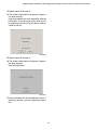
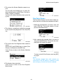
Graph 2 Screen (Single-screen 8channel Graph)
If a sampling operation is being performed, stop it.
On the Digital Data Screen, click the
icon on the
Data List Toolbar or click the
button on the
Function Key Bar twice to display Graph 2 Screen.
Each press of the [F3] button on the Function Key
Bar cycles in the following sequence: → [F3
Graph1] → [F3 Graph2] → [F3 Snapshot] →.
You can also display the Graph 2 Screen by pressing the F3 function key on the PC keyboard twice.
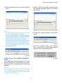
Previewing the Print Image
When there is no sampling operation being performed, click the [File] menu and then select [Print
Preview].
Setting Up the Printer
When there is no sampling operation being performed, click the [File] menu and then select [Setup
printer].
Saving Sampled Data
When there is no sampling operation being performed, click the
icon on the Data List Toolbar,
or the
button on the Function Key Bar. You
could also press the F9 function key on the PC keyboard.
SMU-00587
Graph 2 Screen
Using Non-SI Units to Display Sampled
Data
When there is no sampling operation being performed, click the
button on the Digital Data
Screen or Graph Screen Function Key Bar, or press
the F10 function key on the PC keyboard to display
the sampled data using the currently selected nonSI display units.
NOTE:
• To use this function, the desired display units
should be selected using the window that appears when the [Tool] menu [Option] command is
executed.
• To return to SI unit display, click the
button on the Function Key Bar or press the F10
function key on the PC keyboard.
SMU-00588
Clicking the [G] button in front of an item causes the
[G] button color to change to red, and displays the
name of the item to be displayed for the vertical axis
in the graph area.
Returning to the Fault Diagnosis Menu
Screen
When there is no sampling operation being performed, click the return icon on the Data List Toolbar or the
button on the Function Key Bar.
44
Current Data Display and Save
Setting All Clear Function
To cancel an item selection, click its [G] button
again.
All of the following settings can be returned to their
initial status:
• Item sequence: default setting on each models
• Data Select Screen: all items not selected
• Horizontal axis range of Graph Screen: default
setting on each item
• Vertical axis range of Graph Screen: 0.5 sec/div
• Graph line color of Graph Screen: all red
• Graph line thickness of Graph Screen: 1 point
• Trigger function: without trigger
• Two Cursor Analysis: end of Two Cursor Analysis
While sampling is stopped, click the
icon on the
Data List Toolbar.
SMU-00214
NOTE:
• You can display data for up to eight items on a
single screen.
• The location of item axes depends on the sequence the items are selected. The first four
items that are selected are displayed to the left of
the graph, while the fifth through eighth items selected are displayed to the right.
• You can use the same procedures as those for
Graph 1 Screen, to start and stop sampling, to
move the graph cursor, to display data select, to
change the range, to change the graph line color
and thickness, marking function, etc.
SMU-00694
Functions for Initializing Toolbars
It is possible to initialize the display on each toolbar.
If you initialize the toolbars, the display will be
shown as follows:
• Display or not: Displays all toolbars.
• Position of display: Initial display position.
For initializing the toolbars, select “Initializing the
toolbar” from “View” on the menu.
SMU-00867
45
Sampling Item Memory
Sampling Item Memory
6. On the Main Menu that appears on the display,
select [Each System Check] and then press the
Enter key or left-click with the mouse.
Sampling item memory can be used to configure required sampling items for each abnormality symptom. Then setting files can be read as required for
sampling.
NOTE:
• The setting files described above are called
“mode files”.
• This function may not be available in the case of
certain vehicle models and vehicle specifications.
Creating a Mode File
1. Prepare the SDI, diagnosis cable, USB cable,
and a PC with the PC application installed.
SMU-00600
7. On the System Selection Menu, select [Engine
Control System] and then press the Enter key or
left click with the mouse.
2. Use the diagnosis cable to connect the SDI to the
data link connector of the vehicle.
NOTE:
SDI power will turn on automatically when the diagnosis cable is connected to the vehicle. If the PWR
LED of the SDI does not light, turn on the vehicle’s
ignition switch or start the engine, and then press
the SDI [PWR] key and check again to see if the
PWR LED of the SDI lights.
SMU-00665
8. This displays a compliance verification message
for the system being diagnosed. Click the [OK]
button.
SMU-00113
3. Use the USB cable to connect the SDI to the PC.
4. Turn on the vehicle’s ignition switch.
5. Double-click the SSMΙΙΙ icon on the PC screen to
start up the application.
SMU-00128
46
Sampling Item Memory
9. From the list of fault diagnosis items, select [Select/save sampling items] and then press the Enter key or left-click with the mouse.
11.This displays a save confirmation dialog box.
Click the [Yes] button.
SMU-00501
12.This causes save dialog box of the mode files to
appear.
The name of the data file being saved is generated automatically in accordance with the current
time and date. If you want to use the generated
file name as-is, click the dialog box [Save] button.
If you want to change to a different file name, type
in the name you want.
SMU-00499
10.This displays a sampling item selection screen.
Select the required sampling item and then click,
[Selection Completed].
SMU-00500
NOTE:
If the message dialog box shown below appears
while you are selecting data items, it means that the
limit on the number of selectable data items has
been reached. Selection of further data items is not
possible after this message appears. To select other items, deselect the check boxes next to the currently selected (checked) items, and then select the
new items.
SMU-00502
NOTE:
• Mode files are saved in one of the folders shown
below, which ate located in the directory where
the PC application was installed.
Data folder → Engine or Transmission folder.
To change to another storage location, specify
the location you want in the Save in box of the
Save As dialog box.
• The Comment box of the Save As dialog box can
be used to save general comments associated
with the data or file.
SMU-00154
47
Sampling Item Memory
Reading a Mode File for Sampling
7. On the System Selection Menu, select [Engine
Control System] and then press the Enter key or
left click with the mouse.
NOTE:
This function may not be available in the case of
certain vehicle models and vehicle specifications.
1. Prepare the SDI, diagnosis cable, USB cable,
and a PC with the PC application installed.
2. Use the diagnosis cable to connect the SDI to the
data link connector of the vehicle.
NOTE:
SDI power will turn on automatically when the diagnosis cable is connected to the vehicle. If the PWR
LED of the SDI does not light, turn on the vehicle’s
ignition switch or start the engine, and then press
the SDI [PWR] key and check again to see if the
PWR LED of the SDI lights.
SMU-00665
8. This displays a compliance verification message
for the system being diagnosed. Click the [OK]
button.
SMU-00113
3. Use the USB cable to connect the SDI to the PC.
SMU-00128
4. Turn on the vehicle’s ignition switch.
9. From the list of fault diagnosis items, select [Current Data Display & Save] and then press the Enter key or left-click with the mouse.
5. Double-click the SSMΙΙΙ icon on the PC screen to
start up the application.
6. On the Main Menu that appears on the display,
select [Each System Check] and then press the
Enter key or left-click with the mouse.
SMU-00503
SMU-00600
48
Sampling Item Memory
10.This displays the dialog box shown below. Select {Mode reading/sampling} and then press the
Enter key or left-click with the mouse.
13.This displays the digital data screen.
You can start and stop sampling and perform other operations using the same procedures as
those described under “Current Data Display and
Save”. For details about these operations, see
“Current Data Display and Save”.
SMU-00504
11.This displays a dialog box with a list of saved
files.
Select the desired file and then press the Enter
key or click [Open].
SMU-00589
NOTE:
To display all data after reading a mode file, click
the
icon on the Data List Toolbar or the
button on the Function Key Bar. You can also display to the all data screen by pressing the F11 function key on the PC keyboard.
SMU-00505
12.This displays a sampling start confirmation
screen. Click the [Start sampling] button.
SMU-00506
49
Trigger
Trigger
6. On the Main Menu that appears on the display,
select [Each System Check] and then press the
Enter key or left-click with the mouse.
The trigger feature lets you configure a trigger to be
applied while sampling is in progress. There are two
types of triggers that can be configured: an “Trigger
of input data” that automatically detects the trigger
in accordance with pre-set parameters, and a “Manual trigger” that is triggered manually. When sampling is performed using a trigger, data is stored
from the start of the sampling until the specified time
from trigger detection elapses.
Getting Ready
1. Prepare the SDI, diagnosis cable, USB cable,
and a PC with the PC application installed.
SMU-00600
7. On the System Selection Menu, select the desired system and then press the Enter key or leftclick with the mouse. (As an example, “Engine” is
selected.)
2. Use the diagnosis cable to connect the SDI to the
data link connector of the vehicle.
NOTE:
SDI power will turn on automatically when the diagnosis cable is connected to the vehicle. If the PWR
LED of the SDI does not light, turn on the vehicle’s
ignition switch or start the engine, and then press
the SDI [PWR] key and check again to see if the
PWR LED of the SDI lights.
SMU-00665
SMU-00113
8. This displays a compliance verification message
for the system being diagnosed. Click the [OK]
button.
3. Use the USB cable to connect the SDI to the PC.
4. Turn on the vehicle’s ignition switch.
5. Double-click the SSMΙΙΙ icon on the PC screen to
start up the application.
SMU-00128
50
Trigger
9. From the list of fault diagnosis items, select [Current Data Display & Save] and then press the Enter key or left-click with the mouse.
12.Click the
icon on the Data List Toolbar, or the
button on the Function Key bar. You
could also press the F4 function key on the PC
keyboard.
SMU-00649
13.This displays the setup trigger screen.
SMU-00601
10.This displays the dialog box shown below. Select [Normal sampling] and then press the Enter
key or left-click with the mouse. (As an example,
“Normal sampling” is selected.)
SMU-00508
SMU-00650
11.This displays the Digital Data Screen, so sampling is stopped.
1) Without trigger
Triggering is not performed. Select this option when
you want to cancel the trigger function.
2) Trigger of input data
This setting is used to configure trigger settings for
each sampling item for automatic trigger detection.
3) Manual trigger
With Manual trigger, triggering is performed manually by pressing the trigger switch during data sampling.
The trigger function can be used while the Digital
Data Screen, Graph 1 Screen, or Graph 2 Screen
is displayed.
SMU-00646
51
Trigger
Configuring Trigger of input data
Settings
When a sampling item is not switch input
Configuring triggers to necessary items in advance
automatically detects triggers.
1. On the Specify type of trigger screen, select “Trigger of input data” and then click the [Next] button.
SMU-00653
1) Level
This specifies the trigger level, the value that detects triggers. You can input a value directly into the
box or you can use its up and down arrows to
change the setting. The setting value is limited to
values that can actually be obtained. If you type in a
value that cannot be obtained, the software will automatically change it to the nearest allowable value.
2) Slope condition
This setting specifies the condition for trigger detection when the sample data values reach the trigger
level. When [Both] is selected, a trigger is detected
when either a Upward or Downward condition is first
satisfied.
3) Combinations
When there are multiple triggers, these settings can
be used to configure combinations.
SMU-00651
2. Specify the trigger source.
In the list, select the checkbox next to the item
whose setting you want to change, or doubleclick the item.
When a sampling item is switch input
SMU-00652
3. This displays the Setup trigger of input data
screen. Configure the settings and then click the
[OK] button.
SMU-00654
1) Level
This specifies the trigger level, the value that detects triggers. The setting is configured by button
operation. This setting cannot be selected for certain sampling items.
52
Trigger
2) Slope condition
This setting specifies the data condition for trigger
detection when the sample data values reach the
trigger level.
Selecting [Upward] detects a trigger at the OFF →
ON point.
Selecting [Downward] detects a trigger at the ON →
OFF point.
Selecting [Both] detects a trigger at either the OFF
→ ON point or the ON → OFF point, whichever occurs first.
3) Combinations
When there are multiple triggers, these settings can
be used to configure Combinations.
SMU-00154
5. Setup the action that should be performed after a
trigger is detected.
Configure the settings and then click the [Exit]
button.
4. Checkboxes of the channels to which you set triggers are checked.
If you want to configure multiple triggers, repeat
steps 2 and 3.
After configuring all of the triggers you want, click
the [Next] button.
SMU-00656
1) Time of samples after trigger
This setting is the sampling time after the trigger is detected.
2) Trigger dot display in hold mode transit
This setting specifies the display position of the trigger
detection point (trigger point) when the graph is displayed following sampling.
6. This will display the measurement screen and automatically start sampling. If the trigger is detected
during sampling, data is collected for the specified
time and then sampling stops automatically.
SMU-00655
NOTE:
• To change a trigger setting, select the desired
item and then click the [Edit] button to display the
Setup trigger of input data screen.
• To exclude the setting of an item that is currently
configured for a trigger, clear the check box of the
applicable item.
• If the message dialog box shown below appears
while you are configuring an item setting, it
means that the limit on the number of selectable
items has been reached. Selection of further data
items is not possible after this message appears.
To select other items, deselect the check boxes
next to the currently selected (checked) items you
no longer need, and then select another item to
which you want to assign a trigger.
SMU-00770
53
Trigger
NOTE:
• Assigning an input trigger to an item causes “T” to
appear in item’s checkbox.
• Manual trigger can still be used even if input trigger sampling is in progress. In this case, the sampling time after trigger detection is the same time
set for the Trigger of input data.
• Clicking the
icon on the Data List Toolbar during sampling will terminate sampling immediately, regardless of whether or not there is a trigger.
This is also true if the Function Key Bar
button is clicked or the F2 function key on the PC
keyboard is pressed.
• On the graph, the trigger level is indicated as a
purple chain lines, while the trigger points are indicated by vertical green chain lines.
• Trigger information is displayed on the left side of
the Sampling Status Bar. Clicking the [Details]
button displays an Information of trigger of input
data screen, which you can use to view detailed
information about the currently assigned trigger.
2. Setup the action that should be performed after a
trigger is detected.
Configure the settings and then click the [Exit]
button.
SMU-00656
1) Time of samples after trigger
This setting is the sampling time after the trigger
switch is pressed.
2) Trigger dot display in hold mode transit
This setting specifies the display position of the trigger switch press point (trigger point) when the graph
is displayed following sampling.
3. This will display the measurement screen and automatically start sampling.
When sampling reaches the point where you
want to apply the trigger, click the
button
on the Function Key Bar or the F5 function key on
your PC keyboard. After you do, data is collected
for the specified time and then sampling stops automatically.
SMU-00658
Configuring a Manual Trigger
With a Manual trigger, trigger detection is not performed automatically and a trigger is applied whenever the trigger switch is pressed.
1. On the Specify type of trigger screen, select
“Manual trigger” and then click the [Next] button.
SMU-00771
SMU-00659
54
Trigger
NOTE:
• Clicking the
icon on the Data List Toolbar during sampling will terminate sampling immediately, regardless of whether or not there is a trigger.
This is also true if the Function Key Bar
button is clicked or the F2 function key on the PC
keyboard is pressed.
• On the graph, trigger points are shown as vertical
green chain lines.
• Trigger information is displayed on the left side of
the Sampling Status Bar.
55
Two Cursor Analysis
Two Cursor Analysis
2. Click the
Two Cursor Analysis is provided with two functions:
display cursor numerical value information between
two points, and cut-and-save data.
As cursor numerical value information between two
points, the numerical values of any two points in the
sampled data, and the maximum value, minimum
value and average value between two points can be
calculated and displayed.
For cut-and-save of data, the between any two
points in the sample data can be cut and save.
icon on the Data List Toolbar.
SMU-00707
3. The cursor selection buttons, cursor position
times, cursor interval and [Calculate] button are
displayed on the Sampling Status Bar.
Cursor Numerical Value
Information between Two Points
Cursor numerical value information between two
points can be used in the digital data screen, and either of the Graph 1 Screen or Graph 2 Screen.
Note, however, that on the Graph 1 Screen or
Graph 2 Screen, only selected sampling items are
displayed, and on the digital data screen, all sampling items are displayed.
Cursor numerical value information between two
points can also be used when saved data is re-displayed.
SMU-00708
4. The cursor selection button “Cursor A” is selected. Move graph Cursor A (light blue) to the desired position.
Displaying Numerical Value Information
on a Graph Screen
1. Display the Graph Screen. (The following explanation is for the Graph 1 Screen.)
SMU-00709
5. Select “Cursor B” by the cursor selection button.
Move graph Cursor B (purple) to the desired position.
SMU-00710
SMU-00705
56
Two Cursor Analysis
Displaying Numerical Value Information
on the Digital Data Screen
6. After selecting the sampling item, click the
icon on the Data List Toolbar or the [Calculate]
button on the Sampling Status Bar.
1. Display the digital data screen.
SMU-00712
7. This displays the numerical value information
screen.
To close this screen, click the [OK] button.
SMU-00715
2. Click the
icon on the Data List Toolbar.
SMU-00707
NOTE:
• When displaying the cursor information between
two points, the data value of the currently selected cursor position is displayed as the display value in the value field.
• When displaying the cursor information between
two points, the values between cursors A and B
and not the value from the sampling start point
are displayed as the display value for the maximum, minimum and average values.
SMU-00713
8. To exit the Two Cursor Analysis function, click the
icon again.
3. The cursor selection buttons, cursor position
times and cursor interval are displayed on the
Sampling Status Bar.
SMU-00714
SMU-00716
57
Two Cursor Analysis
4. The cursor selection button “Cursor A” is selected. Move Cursor A to the desired position with
“Cursor A” selected as it is.
7. To exit the Two Cursor Analysis function, click the
icon again.
SMU-00707
SMU-00717
Data Cut-and-Save
NOTE:
In the digital data screen, the cursor is not displayed. So, check the cursor position by the cursor
position time to the side of the cursor selection button.
Data cut-and-save can be used in the digital data
screen, and either of the Graph 1 Screen or Graph
2 Screen.
1. Display the sampling screen. (The following explanation is for the Graph 1 Screen.)
5. Select “Cursor B” by the cursor selection button,
and move Cursor B to the desired position.
SMU-00718
6. Check the numerical value information between
the two cursors.
In the digital data screen, the numerical value information of all sampling items is calculated to linear information and displayed when you move
the cursor position.
SMU-00705
2. Click the
icon on the Data List Toolbar.
SMU-00707
SMU-00719
58
Two Cursor Analysis
3. The cursor selection buttons, cursor position
times, cursor interval and [Calculate] button are
displayed on the Sampling Status Bar.
7. This displays the Select how to save data screen.
Select “Save data between two cursors” and click
the [OK] button.
SMU-00708
4. The cursor selection button “Cursor A” is selected. Move graph Cursor A (light blue) to the desired position.
SMU-00721
NOTE:
If you select “Save All data” at this time, cut-andsave will not be performed, and all sampled data will
be saved.
8. This causes the sampled data save dialog box to
appear. The name of the data file being saved is
generated automatically in accordance with the
current time and date. If you want to use the generated file name as-is, click the dialog box [Save]
button. If you want to change to a different file
name, type in the name you want.
SMU-00709
5. Select “Cursor B” by the cursor selection button.
Move graph Cursor B (purple) to the desired position.
SMU-00710
6. Click the
icon on the Data List Toolbar or the
button on the Function Key Bar. You
could also press the F9 function key on the PC
keyboard.
SMU-00722
SMU-00720
59
Two Cursor Analysis
NOTE:
• Sample data files are saved in the Data folder
where the PC application is installed. To change
to another storage location, specify the location
you want in the Save in box of the save data dialog box.
• The Comment box of the Save As dialog box can
be used to save general comments associated
with the data or file.
• When performing cut-and-save on selected data
in a file containing all data, the save file name
cannot be set to the same name as the save file
containing all data before the cut is performed,
and cannot be saved.
60
Converting Sampled Data to CSV
Converting Sampled Data to
CSV
Converting sampled data to CSV format allows to
analyze the data on a PC without SSMΙΙΙ installed.
Converting sampled data to CSV should be performed on the saved data analysis screen.
NOTE:
Up to 50,000 sampled data can be saved as CSV
file. For more than 50,000 sampled data, data cutand-save can be used to reduce the number of data
before converting to CSV.
How to Convert to CSV from Menu
SMU-00697
1. Double-click the SSMΙΙΙ icon on the PC screen to
start up the application.
3. This displays saved data. Select “Converting
sampling data to CSV” from “File” in menu.
On the Main Menu that appears on the display,
select [Saved Data Display] and then press the
Enter key or left-click with the mouse.
SMU-00824
4. This causes the Save CSV file dialog to appear.
Enter the desired file name, and click the [Save]
button.
SMU-00602
2. The dialog box with a list of saved data files is displayed.
After selecting “Files of type”, designate the file
you need, and press the Enter key or click the
[Open] button.
SMU-00825
NOTE:
• The file name in dafault setting will be the same
name as saved data which is opened.
61
Converting Sampled Data to CSV
• CSV files are saved in the Data folder where the
PC application is installed. To change to another
storage location, specify the location you want in
the Save in box of the save data dialog box.
• If the dialog shown below appears after clicking
the [Save] button, reduce the number of data to
be saved. In this case, convert to CSV in accordance with the procedure in “In the Case of Too
Many Sampled Data”
SMU-00697
SMU-00826
3. Click the
icon on the Data List Toolbar, or the
button on the Function Key bar. You
could also press the F9 function key on the PC
keyboard.
How to Convert to CSV with Save
Icon or Save Button
NOTE:
Converting to CSV with
icon or
button
is effective only when making changes such as added marking etc.
1. Double-click the SSMΙΙΙ icon on the PC screen to
start up the application.
SMU-00577
On the Main Menu that appears on the display,
select [Saved Data Display] and then press the
Enter key or left-click with the mouse.
4. This displays a save dialog. Select “Save data in
CSV (*.csv)” in “Save as type”.
SMU-00602
2. The dialog box with a list of saved data files is displayed.
SMU-00827
After selecting “Files of type”, designate the file
you need, and press the Enter key or click the
[Open] button.
62
Converting Sampled Data to CSV
5. Enter the desired file name, and click the [Save]
button.
1. Display a CSV file save dialog in accordance with
the procedure described before, and click the
[Save] button.
SMU-00828
SMU-00828
NOTE:
• The file name in dafault setting will be the same
name as saved data which is opened.
• CSV files are saved in the Data folder where the
PC application is installed. To change to another
storage location, specify the location you want in
the Save in box of the save data dialog box.
• If the dialog shown below appears after clicking
the [Save] button, reduce the number of data to
be saved. In this case, convert to CSV in accordance with the procedure in “In the Case of Too
Many Sampled Data”
2. This displays a dialog box below. Click the [OK]
button.
SMU-00826
3. The cursor selection buttons, cursor position
times, cursor interval and [Calculate] button are
displayed on the Sampling Status Bar.
SMU-00826
In the Case of Too Many Sampled
Data
SMU-00708
Up to 50,000 data can be converted to CSV. In the
case of more than this, use cut-and-save and convert data to CSV in accordance with the following
procedure.
NOTE:
This describes how to convert to CSV with Save
icon or Save button. However, you can also convert
data to CSV by selecting “Converting sampling data
to CSV” from “File” in menu.
63
Converting Sampled Data to CSV
4. The cursor selection button “Cursor A” is selected. Move graph Cursor A (light blue) to the desired position.
NOTE:
The Select how to save data screen in the next step
can be displayed by selecting “Converting sampling
data to CSV” from “File” in menu.
7. This displays the Select how to save data screen.
Select “Save data between two cursors” and click
the [OK] button.
SMU-00709
5. Select “Cursor B” by the cursor selection button.
Move graph Cursor B (purple) to the desired position.
SMU-00721
8. This displays a save dialog. Select “Save data in
CSV (*.csv)” in “Save as type”.
SMU-00710
NOTE:
At this time, look at the Sampling Status Bar to confirm that the number of data in selected range is less
than 50,000.
SMU-00827
6. Click the
icon on the Data List Toolbar, or the
button on the Function Key bar. You
could also press the F9 function key on the PC
keyboard.
NOTE:
If you select “Converting sampling data to CSV”
from “File” in menu, this step is not necessary.
SMU-00720
64
Converting Sampled Data to CSV
9. Enter the desired file name, and click the [Save]
button.
SMU-00828
NOTE:
• The file name in default setting will be “date and
time” at the time of saving. You can save data
with the same file name as previous one when
converting data to CSV even if you use cut-andsave. (The previous file is not overwritten because their extensions are different.)
• CSV files are saved in the Data folder where the
PC application is installed. To change to another
storage location, specify the location you want in
the Save in box of the save data dialog box.
65
Saving Displayed Data
Saving Displayed Data
NOTE:
• The file name in default setting will be “date and
time” at the time of saving sampled data if you
save sampling data, and it will be the same name
as saved data if you open the saved data.
• Screen data files are saved in the Data folder
where the PC application is installed. To change
to another storage location, specify the location
you want in the Save in box of the save data dialog box.
On the sampling screen or saved data display
screen, you can save the screen as a graphic file.
NOTE:
• Displayed data of sampling result display (except
Roughness Monitor) can be saved.
• The data is saved in BMP (bitmap) format.
How to Save
1. Display the sampling screen or saved data display screen. If you display the sampling screen,
stop sampling.
2. Select “Save displayed data” from “File” in menu.
SMU-00829
3. This causes the displayed data save dialog to appear.
Enter the desired file name, and click the [Save]
button in dialog box.
SMU-00830
66
Saved Data Display
Saved Data Display
3. This recalls the data in the file and displays it on
the Digital Data Screen.
Use the following procedure to recall data that was
saved during fault diagnosis and view it on the PC
display.
NOTE:
Supported data file name extensions are described
below. Use the [Files of types] box to select the file
type you want to view.
.ssm: This extension is used for a file that contains
data saved from the Digital Data Screen or
Graph Screen.
.obd: This extension is used for a file that contains
data saved by OBD system failure diagnosis.
.sdr: This extension is used for a file that contains
data saved by driving recorder.
.biu: This extension is used for a file that contains
data saved a body integrated unit customizing list.
.ocl:
This extension is used for a file that contains
data saved by analog sampling.
1. Double-click the SSMΙΙΙ icon on the PC screen to
start up the application.
On the Main Menu that appears on the display,
select [Saved Data Display] and then press the
Enter key or left-click with the mouse.
SMU-00602
2. The dialog box with a list of saved data files is displayed.
After selecting “Files of type”, designate the file
you need, and press the Enter key or click the
[Open] button.
SMU-00590
NOTE:
You can also view saved data by double clicking the
sample data file.
Opening the folder where the data file is located and
double-clicking the desired file will start up the PC
application automatically and display the data’s
analysis screen. Note, however, that if you start up
the PC application this way, you will not be able to
change to the sampling screen. If you want to sample data, start up the PC application using the procedure under “Starting Up the System”.
SMU-00697
67
Saved Data Display
Display Screen Operations
sample data using the same procedures you use
during data sampling.
You can also save recall data, edit it, and store your
edits.
The Data List Toolbar buttons and the Sampling
Status Bar functions on the saved data display
screen are somewhat different from those on the
Digital Data Screen and Graph Screen. The buttons
and functions on the saved file display screen are
designed to make it easy to find a desired location
within the recalled data.
Multiple display of saved data
Multiple display of data saved by SSMΙΙΙ on the
screen of the personal computer is possible.
There are the following two operation methods for
display.
• Display from the SSMΙΙΙ icon on the screen of the
personal computer.
• Display from the
icon on the Data list toolbar.
Data Scroll Buttons
The data scroll buttons on the Data List Toolbar are
for moving the graph cursor.
Clicking [<] or [>] scrolls back or forward by one
data item. You can also scroll back or forward by 1
data item by pressing the left or right arrow key on
PC keyboard.
Clicking [<<] or [>>] moves the graph cursor one
screen back or forward.
You can also make the graph cursor jump back or
forward by 10 data items by holding down the Ctrl
key and pressing the left or right arrow key on the
PC keyboard.
NOTE:
• Multiple display of saved files is possible for a
maximum of five times.
• Multiple display of the high-grade roughness
monitor saved file (.cym) cannot be done from the
icon on the data list toolbar.
Display from the SSMΙΙΙ icon on the
screen of the personal computer
1. Display one of the targeted saved data.
For the display method, refer to the procedure in
the section “Saved Data Display”.
SMU-00220
Data Cut-and-Save
After displaying previously saved sampling data,
you can cut-and-save parts of the displayed data
and store it in another file.
For information about how to do this, see “Two Cursor Analysis”.
SMU-00590
2. Display the desktop and double-click the SSMΙΙΙ
icon.
On the Main Menu that appears on the display,select [Saved Data Display] and then press
the Enter key or left-click with the mouse.
NOTE:
The name of the data file you take out from the original data CANNOT be the same as that of the original file.
In case of cutting and saving data, the file name
must be changed to something different from the
original file name.
Other Operations
SMU-00890
The marking function, cursor numerical value information between two points, range change, and other similar operations can be performed on recalled
68
Saved Data Display
NOTE:
When multiple saved data are displayed, only a part
of the items of the “Main Menu” is displayed. Accordingly, other items cannot be selected. For use
of the other functions, leave one of the saved data
and close all others. All items of the Main Menu can
be selected when only one saved data is displayed.
SMU-00591
3. The dialog box with a list of saved data files is displayed.
After selecting “Files of type”, designate the file
you need, and press the Enter key or click the
[Open] button.
3. The dialog box with a list of saved data files is displayed.
After selecting “Files of type”, designate the file
you need, and press the Enter key or click the
[Open] button.
SMU-00891
SMU-00891
4. The targeted file is displayed. For additional display of other saved data, return to step 2 and select the saved data.
4. The targeted file is displayed. For additional display of other saved data, return to step 2 and select the saved data.
NOTE:
• Saved data multiple display can also be done by
double-clicking the saved file of sampling data.
By double-clicking multiple files after opening the
folder in which the saved files are saved, the multiple saved data analysis screens are displayed.
however, that if you start up the PC application
this way, you will not be able to change to the
sampling screen. If you want to sample data, start
up the PC application using the procedure under
“Starting Up the System”.
• Multiple display is possible for the following types
of files.
.ssm: This extension is used for a file that contains
data saved from the Digital Data Screen or
Graph Screen.
Display from the
toolbar
icon on the Data list
1. Display one of the targeted saved data.
For the display method, refer to the procedure in
the section “Saved Data Display”.
SMU-00590
2. Click the
icon on the Data List Toolbar.
Select the desired file from the list of files that appears on the display.
69
Saved Data Display
.obd:
This extension is used for a file that contains
data saved by OBD system failure diagnosis.
.sdr: This extension is used for a file that contains
data saved by driving recorder.
.biu:
This extension is used for a file that contains
data saved a body integrated unit customizing list.
.ocl:
This extension is used for a file that contains
data saved by analog sampling.
cym: This extension is used for a file that contains
data saved by High-Grade Roughness
Monitor.
• Multiple display of saved data with the same
name is not possible.
• When SSMΙΙΙ is started again after a .cym file has
been opened and the display language is
switched, the language for the .cym file will not
switch.
• When SSMΙΙΙ is started again after a .biu file has
been opened and the display language is
switched, the language of the .biu file will not be
switched only for the inspection result.
• When the file name of a window minimized to the
taskbar is confirmed, the file name is displayed at
the beginning, but in case of a .cym file, the file
name is displayed at the end.
70
Diagnostic Codes Display
Diagnostic Codes Display
7. On the System Selection Menu, select the desired system and then press the Enter key or leftclick with the mouse. (As an example, “Engine” is
selected.)
Use the following procedure to check the diagnostic
codes memorized by the control module, and cancel codes.
Getting Ready
1. Prepare the SDI, diagnosis cable, USB cable,
and a PC with the PC application installed.
2. Use the diagnosis cable to connect the SDI to the
data link connector of the vehicle.
NOTE:
SDI power will turn on automatically when the diagnosis cable is connected to the vehicle. If the PWR
LED of the SDI does not light, turn on the vehicle’s
ignition switch or start the engine, and then press
the SDI [PWR] key and check again to see if the
PWR LED of the SDI lights.
SMU-00665
8. This displays a compliance verification message
for the system being diagnosed. Click the [OK]
button.
SMU-00113
SMU-00128
3. Use the USB cable to connect the SDI to the PC.
9. From the list of fault diagnosis items, select [Diagnostic Code(s) Display] and then press the Enter
key or left-click with the mouse.
4. Turn on the vehicle’s ignition switch.
5. Double-click the SSMΙΙΙ icon on the PC screen to
start up the application.
6. On the Main Menu that appears on the display,
select [Each System Check] and then press the
Enter key or left-click with the mouse.
SMU-00734
SMU-00600
71
Diagnostic Codes Display
NOTE:
Executing memory clear deletes all diagnostic
codes that are currently memorized by the control
module.
10.Select the desired item and then press the Enter
key or left-click with the mouse.
When no diagnostic codes are displayed
The message shown below appears if there are no
diagnostic codes currently memorized by the control module.
SMU-00543
11.This causes the Diagnostic Code Screen to appear.
SMU-00228
SMU-00230
In accordance with the instructions provided, click
the [OK] button.
NOTE:
The contents of the display screen depend on the
system being diagnosed, vehicle model and specifications, and system fault diagnosis mode.
The message shown below appears if there are no
cancel codes currently memorized by the control
module when cruise control system cancel codes
are checked.
{Latest Diagnostic Code(s)}
This shows the latest diagnostic codes detected by
the control module.
{Memorized Diagnostic Code(s)}
This shows diagnostic codes detected in the past
that are memorized by the control module, and the
latest currently detected diagnostic codes.
SMU-00229
NOTE:
In the case of a vehicle that is demonstrating a fault
that cannot be detected by diagnostic codes, perform repair work in accordance with the fault diagnostic procedures in the Service Manual.
{D-Check Diagnostic Code(s)}
This shows the results of fault diagnosis in the dealer check mode.
When diagnostic codes are displayed
{Temporary Diagnostic Code(s)}
This shows temporary codes detected by the OBD
system.
A screen showing the diagnostic codes and any
message text related to the source of the fault appears if there are diagnostic codes memorized by
the control module.
{Current Diagnostic Code(s)}
This shows diagnostic codes currently detected by
the control module.
{History Diagnostic Code(s)}
This shows diagnostic codes detected in the past
that are memorized by the control module, and the
latest currently detected diagnostic codes.
SMU-00230
72
Diagnostic Codes Display
Executing Memory Clear
Click the
button on the Function Key Bar or
the F2 function key on the PC keyboard.
Printing the Diagnostic Code Screen
Click the
button on the Function Key Bar or
the F8 function key on the PC keyboard.
Returning to the Fault Diagnosis Menu
Screen
Click the
button on the Function Key Bar or
the F12 function key on the PC keyboard.
73
Manual Link (Excluding North America)
Manual Link (Excluding North
America)
* This function is not supported in North America.
Manual Link is the fusion of SSMΙΙΙ and Service
Manual on a PC. Until now it was necessary to
search the Service Manual for each model and then
to search the corresponding page. However, when
a Hybrid-version Service Manual compatible with
Manual Link is installed on a PC where SSMΙΙΙ is installed, the corresponding diagnosis page of the
Service Manual can be found by simple operation
from the DTC detected by “Diagnostic Code(s) Display” of SSMΙΙΙ. Manual Link makes it possible to
aim for better efficiency by reducing the time required to search for the corresponding manual.
SMU-00889
1. Display the DTC check result screen. (Checking
of engine DTC is showed as an example here.)
NOTE:
• This function may not be available in the case of
certain vehicle models.
• The Manual Link function can be used for “All
System Diagnosis” and for “Diagnostic Code(s)
Display” for each system.
• The following software is required to use the
Manual Link function and should be installed in
advance.
Internet Explorer 5.5 or higher (6.0 or higher recommended)
Adobe Acrobat Reader 4.0 or higher
• Please install the Service Manual for each model
to be diagnosed in advance for use of the Manual
Link function. For the installation method, refer to
the Installation Manual by clicking “See Installation Manual” in the menu displayed at the time of
installation of the Hybrid-version Service Manual.
At the time of installation, install the SSMΙΙΙ PC
application first and then the Service Manual.
When the SSMΙΙΙ PC application has not been installed, the Service Manual cannot be installed.
SMU-00881
NOTE:
Refer to the corresponding item for the “Diagnostic
Code(s) Display” procedure.
2. Enter a check mark into the checkbox for the DTC
to be viewed in the Service Manual.
SMU-00882
74
Manual Link (Excluding North America)
NOTE:
A check mark can be entered only for one DTC.
3. Click the
button on the Function Key
Bar, or press the F11 function key on the PC keyboard.
SMU-00883
4. The Manual Selection screen is displayed. Select
the desired manual and click the [OK] button.
SMU-00885
NOTE:
This screen is not displayed when the search result
shows only one model.
6. The fault diagnosis screen for the Service Manual
is displayed. For the operation procedure from
this point on, refer to the “Service Manual Guide”.
SMU-00884
NOTE:
The Service Manual selected here is applied until
return is made to the “System Selection Menu”
screen. When view to a different Service Manual is
desired, return once to the “System Selection
Menu” and restart SSMΙΙΙ.
5. The DTC search result screen for the Service
Manual is displayed. Click the reference
button for the desired model.
SMU-00886
75
Clearing Memory
Clearing Memory
7. On the System Selection Menu, select the desired system and then press the Enter key or leftclick with the mouse. (As an example, “Engine” is
selected.)
Use the following procedure to delete the diagnostic
codes memorized by the control modules of each
system after correcting the fault.
Getting Ready
1. Prepare the SDI, diagnosis cable, USB cable,
and a PC with the PC application installed.
2. Use the diagnosis cable to connect the SDI to the
data link connector of the vehicle.
NOTE:
SDI power will turn on automatically when the diagnosis cable is connected to the vehicle. If the PWR
LED of the SDI does not light, turn on the vehicle’s
ignition switch or start the engine, and then press
the SDI [PWR] key and check again to see if the
PWR LED of the SDI lights.
SMU-00665
8. This displays a compliance verification message
for the system being diagnosed. Click the [OK]
button.
SMU-00113
SMU-00128
3. Use the USB cable to connect the SDI to the PC.
9. From the list of fault diagnosis, select [Clear
Memory] and then press the Enter key or left-click
with the mouse.
4. Turn on the vehicle’s ignition switch.
5. Double-click the SSMΙΙΙ icon on the PC screen to
start up the application.
6. On the Main Menu that appears on the display,
select [Each System Check] and then press the
Enter key or left-click with the mouse.
SMU-00603
SMU-00600
76
Clearing Memory
10.This causes a memory clear confirmation message to appear.
Use the mouse to click the [Yes] button.
SMU-00239
Executing the memory clear operation causes the
message shown below to appear. In accordance
with the instructions of the message, turn off the
vehicle’s ignition switch and then use the mouse
button to click [OK].
SMU-00240
NOTE:
Also, there are some systems that do not have a
memory clear item on the fault diagnosis screen.
With such a system, the dialog box will disappear
from the display when you turn off the vehicle’s ignition switch.
Transmission System Memory Clear 2
On the fault diagnosis screen for the transmission
system, [Clear Memory] and [Clear Memory 2]
items may be displayed.
Selecting the [Clear Memory 2] item deletes diagnostic codes and learning control values memorized by the transmission control module.
Airbag System Memory Clear
To execute the memory clear operation in the airbag system, you must first completely service all
problems. If there is even one problem remaining,
the memory clear operation cannot be executed.
77
System Operation Check Mode
System Operation Check Mode
6. On the Main Menu that appears on the display,
select [Each System Check] and then press the
Enter key or left-click with the mouse.
Use the following procedure to force operation of
engine control system actuators to check their operation.
NOTE:
This function is not supported in some vehicle models.
Getting Ready
1. Prepare the SDI, diagnosis cable, USB cable,
and a PC with the PC application installed.
2. Use the diagnosis cable to connect the SDI to the
data link connector of the vehicle.
SMU-00600
7. On the System Selection Menu, select [Engine
Control System] and then press the Enter key or
left-click with the mouse.
NOTE:
SDI power will turn on automatically when the diagnosis cable is connected to the vehicle. If the PWR
LED of the SDI does not light, turn on the vehicle’s
ignition switch or start the engine, and then press
the SDI [PWR] key and check again to see if the
PWR LED of the SDI lights.
SMU-00113
SMU-00665
3. Use the USB cable to connect the SDI to the PC.
8. This displays a compliance verification message
for the system being diagnosed. Click the [OK]
button.
4. Turn on the vehicle’s ignition switch.
5. Double-click the SSMΙΙΙ icon on the PC screen to
start up the application.
SMU-00128
78
System Operation Check Mode
Actuator ON/OFF Operation
9. From the list of fault diagnosis, select [System
Operation Check Mode] and then press the Enter
key or left-click with the mouse.
This function is used to perform test operation of
various actuators related to the engine control system. The test mode connector needs to be connected in order to perform the test.
Selecting actuator ON/OFF operation on the system operation check mode screen causes the
screen shown below to appear. Select the desired
item and then click the
button to force operation of the actuators for testing.
SMU-00604
10.This displays a system operation check mode
menu screen.
Select the desired item and then press the Enter
key or left-click with the mouse.
SMU-00248
NOTE:
Make sure the vehicle’s ignition switch is off before
connecting or disconnecting the test mode connector.
SMU-00877
IMPORTANT:
In System Operation Check Mode, if you work on
this in the mode with the engine started, it must only
be done when the engine is idling. It is very dangerous if you work on this mode while the vehicle is
running, because the engine may stall or the brakes
may lose some of the braking force depending on
the settings.
Fuel Pump Control
This function has 2 modes: the fuel pump “OFF
Drive” mode and the fuel pump “ON/OFF
Drive”mode.
NOTE:
• The test mode connector does not need to be
connected to operate this function.
• Always execute “Clear Memory” after operating
this function.
NOTE:
The display items that appear depend on the model
and specifications of the vehicle on which fault diagnosis is being performed.
OFF Drive
Use this function to turn the fuel pump OFF and remove the residual pressure in the fuel pipe.
Follow the on-screen instructions to execute this
procedure.
79
System Operation Check Mode
Injector Control
IMPORTANT:
This mode should be executed at the time of idling.
When the accelerator pedal has been depressed
etc., so that the engine is not in idling condition, this
mode is stopped and the fuel pump becomes ON.
This function has two modes: “Injection Stop Mode”
and “Injection Quantity Control” mode.
NOTE:
• The test mode connector does not need to be
connected to operate this function.
• Always execute “Clear Memory” after operating
this function.
ON/OFF Drive
Use this function to turn the fuel pump ON/OFF and
remove the fuel in the fuel tank.
Follow the on-screen instructions to execute this
procedure.
Injection Stop Mode
This function allows you to stop any cylinder injector
when identifying which cylinder is malfunctioning.
Follow the on-screen instructions to execute this
procedure.
IMPORTANT:
Do not operate the fuel pump if there is no fuel in the
fuel tank; otherwise, the fuel pump may be damaged.
Injection Quantity Control
Fixed Idle Ignition Timing
The injection quantity can be increased according
to the set percentage. This function can be used in
cases such as when the engine is not running properly and you need to check whether the problem is
a lean air-fuel ratio.
Follow the on-screen instructions to execute this
procedure.
This function fixes the ignition timing during idling,
and by stopping the “idle ignition timing correction”,
it allows you to check the basic idle ignition timing
and whether the idle ignition timing control is operating properly. Follow the on-screen instructions to
execute this procedure.
NOTE:
• The test mode connector does not need to be
connected to operate this function.
• The ignition timing fixed value varies depending
on the vehicle model. Also, the fixed value cannot
be changed.
• The engine speed may vary while this mode is
operated.
• Always execute “Clear Memory” after operating
this function.
IMPORTANT:
• Keep in mind that increasing the injection quantity
may cause fuel to stick to the spark plugs, resulting in engine malfunction.
• Avoid running the engine for a long period of time
with the injection quantity increased, or else the
emissions will deteriorate.
EGR Valve Control
This function allows you to operate the EGR valve
in a preset number of steps and control the EGR
rate to a desired value. It is a means of checking
whether or not the EGR valve is working properly.
Follow the on-screen instructions to execute this
procedure.
Idle Speed Control
This function allows you to set the idle speed you
want.
Follow the on-screen instructions to execute this
procedure.
NOTE:
• The test mode connector does not need to be
connected to operate this function.
• The number of steps that can be set varies depending on the vehicle models.
• Always execute “Clear Memory” after operating
this function.
NOTE:
• The test mode connector does not need to be
connected to operate this function.
• Depending on conditions such as vehicle model
and elevation, the actual idle speed may not go
up when the idle speed setting is raised.
• Always execute “Clear Memory” after operating
this function.
80
Dealer Check Mode Procedure
Dealer Check Mode Procedure
7. On the Main Menu that appears on the display,
select [Each System Check] and then press the
Enter key or left-click with the mouse.
This function can be used to perform inspection of a
simplified dealer check by performing operations as
prompted by messages that appear on the PC display.
The Dealer check mode procedure is one of the
self-diagnostic functions of the control module. The
dealer check mode provides the means to perform
more thorough system fault diagnosis.
Getting Ready
1. Prepare the SDI, diagnosis cable, USB cable,
and a PC with the PC application installed.
SMU-00600
2. Use the diagnosis cable to connect the SDI to the
data link connector of the vehicle.
8. On the System Selection Menu, select [Engine
Control System] and then press the Enter key or
left-click with the mouse.
NOTE:
SDI power will turn on automatically when the diagnosis cable is connected to the vehicle. If the PWR
LED of the SDI does not light, turn on the vehicle’s
ignition switch or start the engine, and then press
the SDI [PWR] key and check again to see if the
PWR LED of the SDI lights.
SMU-00665
SMU-00113
9. This displays a compliance verification message
for the system being diagnosed. Click the [OK]
button.
3. Use the USB cable to connect the SDI to the PC.
4. Connect the test connector. (Make sure that the
vehicle’s ignition switch is OFF.)
5. Turn on the vehicle’s ignition switch.
6. Double-click the SSMΙΙΙ icon on the PC screen to
start up the application.
SMU-00128
81
Dealer Check Mode Procedure
Entering the Dealer Check Mode
10.From the list of fault diagnosis item, select [Dealer Check Mode Procedure] and then press the
Enter key or left-click with the mouse.
SMU-00256
As instructed by the display message, turn on the
vehicle’s ignition switch (make sure that the engine
is currently not running).
Click
button to advance to the next
screen, or the
button to return to a previous screen. To exit the Dealer check mode, click the
button.
SMU-00605
This displays an operation confirmation message. As instructed by the message, click the
button.
Check Engine Lamp Check
SMU-00255
This displays the Dealer check mode operation
instruction screen. Perform Dealer check mode
operations in accordance with the instructions
that appear.
SMU-00260
Inspect the check engine lamp to see if it is lit or
flashing.
NOTE:
• The test mode connector must be connected in
order to perform the Dealer check mode.
• When performing the Dealer check mode while
the vehicle is in operation, never allow the driver
to operate the SSMΙΙΙ or SDI.
If the check engine lamp is lit or flashing, click the
button. Click the
button to return to a previous screen or the
button to
cancel the Dealer check mode.
NOTE:
If the check engine lamp is not lit, perform fault diagnosis on the check engine lamp circuit as detailed
in the Service Manual.
82
Dealer Check Mode Procedure
Actuator Operation Check
Engine Start
SMU-00264
SMU-00272
This procedure checks for proper operation of the
various actuators of the fuel pump, radiator fan, and
other engine control system-related components.
Start the engine of the vehicle.
Click
button to advance to the next
screen, or the
button to return to a previous screen. To exit the Dealer check mode, click the
button.
When an actuator is operating normally, click
button to advance to the next screen, or
the
button to return to a previous screen.
To exit the Dealer check mode, click the
button.
Vehicle Speed Signal Check
NOTE:
If an actuator abnormality is discovered, perform
fault diagnosis in accordance with the Service Manual.
Throttle Valve Position Sensor Input
Signal Check
SMU-00276
Run the vehicle at a speed of at least 10km/h (6
MPH).
IMPORTANT:
When performing the Dealer check mode while the
vehicle is in operation, never allow the driver to operate the SSMΙΙΙ or SDI.
SMU-00268
Click
button to advance to the next
screen, or the
button to return to a previous screen. To exit the Dealer check mode, click the
button.
Slowly press the accelerator pedal down as far as it
will go, and then release it.
Click
button to advance to the next
screen, or the
button to return to a previous screen. To exit the Dealer check mode, click the
button.
83
Dealer Check Mode Procedure
O2 Sensor Check
When a fault is detected by the Dealer
check mode procedure
The applicable diagnostic code appears when a
fault is detected.
Check the diagnostic codes, and perform repair
work in accordance with Service Manual fault diagnosis procedures.
SMU-00280
Increase engine speed to the range of 2000 to 3000
rpm, and keep it there for at least one minute.
A diagnostic result display will appear after the
Dealer check mode is complete.
To cancel the Dealer check mode part way through,
click the
button.
SMU-00284
NOTE:
After completing the Dealer check mode procedure,
turn off the vehicle’s ignition switch and disconnect
the test mode connector.
When no fault is detected by the Dealer
check mode procedure
The dialog box shown below appears when no fault
is detected.
Click the [OK] button.
SMU-00282
This displays dealer check mode ending screen.
Click the [Exit] button to complete the check.
SMU-00283
84
OBD System
OBD System
6. On the Main Menu that appears on the display,
select [Each System Check] and then press the
Enter key or left-click with the mouse.
Vehicle fault diagnosis can be performed by checking the OBD system control parameters.
NOTE:
This function cannot be performed if the vehicle is
not equipped with an OBD system.
Getting Ready
1. Prepare the SDI, diagnosis cable, USB cable,
and a PC with the PC application installed.
2. Use the diagnosis cable to connect the SDI to the
data link connector of the vehicle.
SMU-00600
NOTE:
SDI power will turn on automatically when the diagnosis cable is connected to the vehicle. If the PWR
LED of the SDI does not light, turn on the vehicle’s
ignition switch or start the engine, and then press
the SDI [PWR] key and check again to see if the
PWR LED of the SDI lights.
7. On the System Selection Menu, select the desired system and then press the Enter key or leftclick with the mouse. (As an example, “Engine” is
selected.)
SMU-00113
3. Use the USB cable to connect the SDI to the PC.
4. Turn on the vehicle’s ignition switch.
SMU-00665
5. Double-click the SSMΙΙΙ icon on the PC screen to
start up the application.
8. This displays a compliance verification message
for the system being diagnosed. Click the [OK]
button.
SMU-00128
85
OBD System
9. From the list of fault diagnosis items, select [OBD
System] and then press the Enter key or left-click
with the mouse.
The following describes the items that appear on
this screen.
All data display
Use this item to check OBD system diagnostic results, and control module input signals, which are
needed for diagnosis.
SMU-00592
SMU-00606
Analog data display Menu
10.This causes the OBD system menu screen to
appear.
Use this item to check control module input signals
and control module control data.
Select the desired item and then click the mouse.
NOTE:
The items that appear depend on the system being
diagnosed.
SMU-00593
O2 sensor system data display
Use this item to check O2 sensor-related control
module input signals and control data.
SMU-00545
SMU-00594
Current Data Display & Save
Selecting [Current Data Display & Save] on the
OBD menu screen displays the screen shown below.
Diagnosis process display
Use this item to check OBD system diagnostic results.
SMU-00595
SMU-00546
86
OBD System
Saved Data Display
Diagnostic Code Display
Use this item to recall and check data saved with
the SSMΙΙΙ OBD system.
On the file type dialog box, select “OBD sampling
data (*.obd)”.
Selecting [Diagnostic Code(s) Display] on the OBD
menu displays a screen like the one shown below.
This screen can be used to check diagnostic codes
detected by the OBD system.
SMU-00298
Diagnostic Code Clear
Selecting [Diagnostic Code(s) Cleared] on the OBD
menu displays a dialog box like the one shown below.
As instructed by the dialog box text, click the [Yes]
button to delete the diagnostic codes memorized by
the control module.
SMU-00698
Freeze Frame Data Display
Selecting [Freeze Frame Data Display] on the OBD
menu displays a screen like the one shown below.
This screen can be used to check the input data to
the control module at the point that the OBD system
fault is detected.
The dialog box at the top of the screen can be used
to select and display the data for up to three fault
detection instances.
SMU-00299
Executing the diagnostic clear operation causes the
message shown below to appear.
Click the [OK] button.
SMU-00297
SMU-00300
87
OBD System
O2 Sensor Monitor
Get Vehicle Info
Selecting [O2 Sensor Monitor Test] on the OBD
menu displays a screen like the one shown below.
(This display screen is an example.)
The O2 sensor related control module input signal
and control data screen can be displayed by selecting the item on the display that conforms to the vehicle being inspected. This makes it possible to
check the current O2 sensor status.
Selecting [Getting of vehicle information] on the
OBD menu displays a screen like the one shown
below.
SMU-00304
SMU-00547
NOTE:
Some functions may not be available in the case of
certain vehicle models and vehicle specifications.
Onboard Monitor Test Results
Selecting [Result of on-board monitor test] on the
OBD menu displays a screen like the one shown
below.
SMU-00302
Temporary Code Check
Selecting [Temporary Code(s) Inspection] on the
OBD menu displays a screen like the one shown
below.
This screen shows temporary codes detected by
the OBD system.
SMU-00303
88
Function Check Sequence
Function Check Sequence
6. On the Main Menu that appears on the display,
select [Each System Check] and then press the
Enter key or left-click with the mouse.
The brake control system fault diagnosis screen includes a function check sequence item. The function check sequence can be used to perform checks
of ABS system and VDC system hydraulic control
valve operation, and to set the center point of the
VDC system steering angle sensor and the 0 point
of the lateral G sensor.
Getting Ready
1. Prepare the SDI, diagnosis cable, USB cable,
and a PC with the PC application installed.
2. Use the diagnosis cable to connect the SDI to the
data link connector of the vehicle.
SMU-00600
7. On the System Selection Menu, select [Brake
Control System] and then press the Enter key or
left-click with the mouse.
NOTE:
SDI power will turn on automatically when the diagnosis cable is connected to the vehicle. If the PWR
LED of the SDI does not light, turn on the vehicle’s
ignition switch or start the engine, and then press
the SDI [PWR] key and check again to see if the
PWR LED of the SDI lights.
SMU-00113
SMU-00669
3. Use the USB cable to connect the SDI to the PC.
8. This displays a compliance verification message
for the brake control system. Click the [OK] button.
4. Turn on the vehicle’s ignition switch.
5. Double-click the SSMΙΙΙ icon on the PC screen to
start up the application.
SMU-00308
89
Function Check Sequence
VDC Function Check Mode
9. From the list of fault diagnosis items, select
[Function Check Sequence] and then press the
Enter key or left-click with the mouse.
Selecting the check sequence for a vehicle
equipped with a VDC causes the screen shown below to appear.
Perform the procedure as instructed by the text on
the screen will automatically enter the VDC function
check mode and perform a hydraulic control valve
operation check.
SMU-00607
ABS Function Check Mode
SMU-00413
Selecting the check sequence for a vehicle
equipped with an ABS causes the screen shown below to appear.
Perform the procedure as instructed by the text on
the screen will automatically enter the ABS function
check mode and perform a hydraulic control valve
operation check.
NOTE:
• Connection of the test mode connector is not required for this check.
• Be sure to refer to the Service Manual when performing this check.
Steering Angle Sensor Neutral and
Lateral G Sensor Zero Setting
Mode
Selecting the steering angle sensor neutral and lateral G sensor zero setting mode for a vehicle
equipped with a VDC causes the screen shown below to appear.
Follow the instructions that appear on the screen to
set steering sensor neutral and lateral G sensor zero.
SMU-00670
NOTE:
• Keep the brake pedal depressed until the check
is complete. Releasing the brake pedal while
checking is part way through will result in an incorrect check.
• Connection of the test mode connector is not required for this check.
• Be sure to refer to the Service Manual when performing this check.
SMU-00414
NOTE:
• Connection of the test mode connector is not required for this check.
• Be sure to refer to the Service Manual when performing this setting operation.
90
Fault Data Display
Fault Data Display
6. On the Main Menu that appears on the display,
select [Each System Check] and then press the
Enter key or left-click with the mouse.
This display makes it possible to check control module input data and the module control status when
the brake control system control module detects a
fault.
Getting Ready
1. Prepare the SDI, diagnosis cable, USB cable,
and a PC with the PC application installed.
2. Use the diagnosis cable to connect the SDI to the
data link connector of the vehicle.
NOTE:
SDI power will turn on automatically when the diagnosis cable is connected to the vehicle. If the PWR
LED of the SDI does not light, turn on the vehicle’s
ignition switch or start the engine, and then press
the SDI [PWR] key and check again to see if the
PWR LED of the SDI lights.
SMU-00600
7. On the System Selection Menu, select [Brake
Control System] and then press the Enter key or
left-click with the mouse.
SMU-00113
3. Use the USB cable to connect the SDI to the PC.
4. Turn on the vehicle’s ignition switch.
SMU-00669
5. Double-click the SSMΙΙΙ icon on the PC screen to
start up the application.
8. This displays a compliance verification message
for the brake control system. Click the [OK] button.
SMU-00308
91
Fault Data Display
9. From the list of fault diagnosis items, select
[Freeze Frame Data] and then press the Enter
key or left-click with the mouse.
SMU-00608
10.Selecting [Freeze Frame Data] displays a
screen like the one shown below.
The select box at the top of the screen can be
used to select and display the data for up to three
fault detection instances.
SMU-00316
NOTE:
• The control module always maintains the three
latest fault information entries in memory.
• If the screen shows a diagnostic code with a
question mark (?), it means that the fault information was not stored correctly by the control module when the fault was detected.
92
Selection of Parameter
Selection of Parameter
4. Turn on the vehicle’s ignition switch.
This function is used to select/register parameters
when the VDC control module has been replaced
with a normal spare part.
5. Double-click the SSMΙΙΙ icon on the PC screen to
start up the application.
6. On the Main Menu that appears on the display,
select [Each System Check] and then press the
Enter key or left-click with the mouse.
NOTE:
• Always execute “Clear Memory” after operating
this function.
• This function cannot be used with a control module that is not a normal spare part.
• To confirm the applied model, refer to the “model
No. plate” affixed to the vehicle. The location of
the model No. plate is shown in the Service Manual.
SMU-00600
7. On the System Selection Menu, select [Brake
Control System] and then press the Enter key or
left-click with the mouse.
SMU-00868
Registration Procedure
1. Prepare the SDI, diagnosis cable, USB cable,
and a PC with the PC application installed.
2. Use the diagnosis cable to connect the SDI to the
data link connector of the vehicle.
NOTE:
SDI power will turn on automatically when the diagnosis cable is connected to the vehicle. If the
PWRLED of the SDI does not light, turn on the vehicle's ignition switch or start the engine, and then
press the SDI [PWR] key and check again to see if
the PWR LED of the SDI lights.
SMU-00669
8. This displays a compliance verification message
for the system being diagnosed. Click the [OK]
button.
SMU-00113
3. Use the USB cable to connect the SDI to the PC.
SMU-00869
93
Selection of Parameter
9. From the list of fault diagnosis, select [Selection
of Parameter] and then press the Enter key or
left-click with the mouse.
NOTE:
If the applied model and grade are different than
those of the vehicle, execute the registration procedure again after clicking the [OK] button.
SMU-00870
10.Input the applied model and press the Enter key.
SMU-00871
11.Stand by as the message below will appear on
the screen.
SMU-00872
12.The vehicle information check screen will be displayed.
Make sure that the applied model and grade
shown on the screen are correct and then click
the [OK] button.
SMU-00873
94
Confirm on Parameter
Confirm on Parameter
This function allows you to confirm the parameters
registered in the VDC control module.
NOTE:
This function can be used even if the VDC control
module is not a normal spare part.
Confirm Procedure
1. Prepare the SDI, diagnosis cable, USB cable,
and a PC with the PC application installed.
SMU-00600
7. On the System Selection Menu, select [Brake
Control System] and then press the Enter key or
left-click with the mouse.
2. Use the diagnosis cable to connect the SDI to the
data link connector of the vehicle.
NOTE:
SDI power will turn on automatically when the diagnosis cable is connected to the vehicle. If the
PWRLED of the SDI does not light, turn on the vehicle's ignition switch or start the engine, and then
press the SDI [PWR] key and check again to see if
the PWR LED of the SDI lights.
SMU-00669
8. This displays a compliance verification message
for the system being diagnosed. Click the [OK]
button.
SMU-00113
3. Use the USB cable to connect the SDI to the PC.
4. Turn on the vehicle’s ignition switch.
5. Double-click the SSMΙΙΙ icon on the PC screen to
start up the application.
6. On the Main Menu that appears on the display,
select [Each System Check] and then press the
Enter key or left-click with the mouse.
SMU-00869
95
Confirm on Parameter
9. From the list of fault diagnosis, select [Confirm on
Parameter] and then press the Enter key or leftclick with the mouse.
SMU-00874
10.The parameter confirm screen will be displayed.
Make sure the “Applied model” and “Grade” of the
pertinent vehicle are displayed, and then click the
[OK] button.
SMU-00875
96
Body Integrated Module Destination Market Registry (Excluding North America and Japan)
Body Integrated Module
Destination Market Registry
(Excluding North America and
Japan)
When the body integrated module has been replaced by a normal spare part, the vehicle destination information is set to the body integrated
module.
NOTE:
• Body integrated module destination registry is a
function for markets other than North America
and Japan.
• This function cannot be used with a control module that is not a normal spare part.
• Upon replacement of body integrated module, vehicle destination input is necessary. Please confirm market destination of the vehicle which the
module replacement is to be performed, before
the module is replaced by a spare part.
SMU-00672
4. This displays a compliance verification message
for the system being diagnosed. Click the [OK]
button.
Confirmation of Vehicle
Destination (Part 1)
Confirm the vehicle destination registered in the
body integrated module prior to replacement.
SMU-00380
1. Start the PC application according to section
"Starting Up the System" and display the Main
Menu screen.
5. From the list of fault diagnosis items, select [Current Data Display & Save] and then press the Enter key or left-click with the mouse.
2. On the Main Menu that appears on the display,
select [Each System Check] and then press the
Enter key or left-click with the mouse.
SMU-01103
SMU-00600
3. On the System Selection Menu, select [Integ. unit
mode] and then press the Enter key or left-click
with the mouse.
97
Body Integrated Module Destination Market Registry (Excluding North America and Japan)
6. When digital data is displayed as shown below,
scroll down and confirm the item [Destination Setting]. The value shown defines the market the vehicle is destined for.
Model Number Label
Destination
Arabic
KS
SMU-01104
Confirmation of Vehicle
Destination (Part 2)
SMU-01106
If market destination is impossible to obtain digitally
(e.g. when the body integrated module is out of order), refer to [Model Number Label] fixed onto the
vehicle itself.
The location of the model number label is shown in
the Service Manual.
Model Number Label
Destination
Non-Arabic
EC, EL, EA, EH, E2, EP,
K4, K5
For right-hand drive models
Confirm vehicle destination by “Applied Model”
number row of the model number label, in which 5th
out of 7 digits (count from left) distinguish the market vehicle is intended for.
Applied Model
Number
5th Digit
Destination
****K**
K
EK, ER
****4**
****5**
4 or 5
JP
SMU-01105
SMU-01110
For left-hand drive models
Destination market is distinguished by whether the
model number label is in Arabic or not.
98
Body Integrated Module Destination Market Registry (Excluding North America and Japan)
Registration Steps for Registering
Vehicle Destination
1. After the vehicle destination is confirmed, replace
the body integrated module with a fresh spare.
NOTE:
Please refer to Service Manual for instruction of
body integrated module replacement.
2. Begin destination registry for the spare body integrated module.
First, follow steps shown in column 1 through 4 of
[Confirmation of vehicle destination (Part 1)]
shown above.
SMU-01108
Option Code Correlation Table
Destination
3. From the list of fault diagnosis items, select [Integ. Unit customizing] and then press the Enter
key or left-click with the mouse.
Option Code
JPN
JP00
EK , ER
EK00
EC, EL, EA, EH, E2, EP,
K4, K5
EC00
KS
KS00
6. Screen will then display message shown below.
Reconfirm the displayed vehicle destination with
the one identified by steps previously mentioned,
then click [OK] to conclude the registry operation.
SMU-00674
4. The screen shown below will appear. Click the
[OK] button.
SMU-01109
NOTE:
If the applied model and grade are different than
those of the vehicle, execute the registration procedure again after clicking the [Cancel] button.
SMU-01107
5. Option code registry screen will then be displayed. Refer to [Option Code Correlation Table]
shown below, enter the option code matching the
destination correlating to the result of steps
shown above, and then click [OK].
99
Body Integrated Module Function Check
Body Integrated Module
Function Check
6. On the Main Menu that appears on the display,
select [Each System Check] and then press the
Enter key or left-click with the mouse.
The following procedure can be used to force operation of the various actuators that control the body
integrated module and check their operation.
Getting Ready
1. Prepare the SDI, diagnosis cable, USB cable,
and a PC with the PC application installed.
2. Use the diagnosis cable to connect the SDI to the
data link connector of the vehicle.
NOTE:
SDI power will turn on automatically when the diagnosis cable is connected to the vehicle. If the PWR
LED of the SDI does not light, turn on the vehicle’s
ignition switch or start the engine, and then press
the SDI [PWR] key and check again to see if the
PWR LED of the SDI lights.
SMU-00600
7. On the System Selection Menu, select [Integ. unit
mode] and then press the Enter key or left-click
with the mouse.
SMU-00113
3. Use the USB cable to connect the SDI to the PC.
4. Turn on the vehicle’s ignition switch.
SMU-00672
5. Double-click the SSMΙΙΙ icon on the PC screen to
start up the application.
8. This displays a compliance verification message
for the system being diagnosed. Click the [OK]
button.
SMU-00380
100
Body Integrated Module Function Check
9. From the list of fault diagnosis items, select
[Function check] and then press the Enter key or
left-click with the mouse.
This forces operation of the actuator(s). After
checking the operational status of the actuator(s),
click the [Exit] button.
SMU-00673
On the screen that appears, select the actuator(s)
to be checked, and then click the [Next] button.
SMU-00384
This causes a confirmation message to appear.
Click the [OK] button.
NOTE:
• A check mark will not appear next to an actuator
when it is selected on the screen if the selected
actuator is not equipped on the vehicle.
• Perform the shift lock solenoid operation check in
the P range.
SMU-00385
If the function check reveals abnormal operation
in any actuator, perform repair work in accordance with the Service Manual.
SMU-00520
This displays a screen for confirming operation of
the selected actuator(s). Click the [Next] button.
SMU-00383
101
Body Integrated Module Function Setting (Integ.Unit Customizing)
Body Integrated Module
Function Setting (Integ.Unit
Customizing)
6. On the Main Menu that appears on the display,
select [Each System Check] and then press the
Enter key or left-click with the mouse.
The following procedure can be used to configure
operational details, operation time, and other settings for the actuators controlled by the body integrated module.
IMPORTANT:
Make sure you perform setting operations in accordance with the Service Manual when using the
unit customization function. Configuring the wrong
settings can cause abnormal system operation and
other problems.
SMU-00600
7. On the System Selection Menu, select [Integ. unit
mode] and then press the Enter key or left-click
with the mouse.
Getting Ready
1. Prepare the SDI, diagnosis cable, USB cable,
and a PC with the PC application installed.
2. Use the diagnosis cable to connect the SDI to the
data link connector of the vehicle.
NOTE:
SDI power will turn on automatically when the diagnosis cable is connected to the vehicle. If the PWR
LED of the SDI does not light, turn on the vehicle’s
ignition switch or start the engine, and then press
the SDI [PWR] key and check again to see if the
PWR LED of the SDI lights.
SMU-00672
8. This displays a compliance verification message
for the system being diagnosed. Click the [OK]
button.
SMU-00113
3. Use the USB cable to connect the SDI to the PC.
4. Turn on the vehicle’s ignition switch.
5. Double-click the SSMΙΙΙ icon on the PC screen to
start up the application.
SMU-00380
102
Body Integrated Module Function Setting (Integ.Unit Customizing)
9. From the list of fault diagnosis items, select [Integ.Unit customizing] and then press the Enter
key or left-click with the mouse.
SMU-01107
SMU-00674
This displays a customized setting screen for the
selected item(s). Select the desired setting(s),
and then click the [OK] button.
On the screen that appears, select the setting(s)
to be configured, and then click the [Next] button.
SMU-00408
This causes a message to appear indicating that
setting configuration is complete. Click the [OK]
button.
SMU-00391
NOTE:
• Make sure you perform setting operations in accordance with the Service Manual. Configuring
the wrong settings can cause abnormal system
operation and other problems.
• If there is no destination registry in the body integrated module, the screen may display message
shown below.
In such case, please refer to item [Body Integrated Module Destination Market Registry (Excluding Japan and North America)], and perform
destination registry.
SMU-00415
103
Display the List of Function Setting (Integ.Unit Customizing)
Display the List of Function
Setting (Integ.Unit
Customizing)
You can display, print, or save a list of Function Setting (Integ.Unit Customizing) status for body integrated module.
On the list, you can enter information, such as “Vehicle Registration Number”, “Vehicle Number”, etc.
NOTE:
The customized setting cannot be changed from
this function. To change customized setting, perform from “Integ.Unit customizing”.
SMU-00856
7. On the Others Menu, select [Customized Setting]
and then press the Enter key or left-click with the
mouse.
How to Display the List
1. Prepare the SDI, diagnosis cable, USB cable,
and a PC with the PC application installed.
2. Use the diagnosis cable to connect the SDI to the
data link connector of the vehicle.
NOTE:
SDI power will turn on automatically when the diagnosis cable is connected to the vehicle. If the PWR
LED of the SDI does not light, turn on the vehicle's
ignition switch or start the engine, and then press
the SDI [PWR] key and check again to see if the
PWR LED of the SDI lights.
SMU-00857
8. This displays the list of Function Setting status for
body integrated module.
Enter information into the items; Customer's
Name / Vehicle Registration Number / Vehicle
Number / Dealership / Inspector’s Name.
Confirm the entered items and then click the
[Completion of data entry] button.
SMU-00113
3. Use the USB cable to connect the SDI to the PC.
4. Turn on the vehicle's ignition switch.
5. Double-click the SSMΙΙΙ icon on the PC screen to
start up the application.
SMU-00878
6. On the Main Menu that appears on the display,
select [Others] and then press the Enter key or
left-click with the mouse.
NOTE:
The items displayed in the list depend on vehicle
model and specifications.
104
Display the List of Function Setting (Integ.Unit Customizing)
9. This displays a confirmation dialog box for the
function setting status. Click the [Yes] button.
SMU-00859
10.After completing confirmation of function setting
status, data will be input in blanks. This also displays a save confirmation dialog box simultaneously.
SMU-00862
NOTE:
• The function setting status file is saved in the
Data folder where the PC application is installed.
To change to another storage location, specify
the location you want in the Save in box of the
save data dialog box.
• The Comment box of the Save As dialog box can
be used to save general comments associated
with the data or file.
Displaying Saved Files
1. On the Main Menu, select [Saved Data Display]
and then click with the mouse.
SMU-00879
NOTE:
“-” may be displayed in the case of certain vehicle
models and vehicle specifications.
11.To save displayed data, click the [Yes] button in
the save confirmation dialog box.
SMU-00863
SMU-00861
12.This displays the “Save As” dialog box.
The name of the data file being saved is generated automatically in accordance with the current
time and date. If you want to use the generated
file name as-is, click the dialog box [Save] button.
If you want to change to a different file name, type
in the name you want.
105
Display the List of Function Setting (Integ.Unit Customizing)
2. This displays the “Open” dialog box. Click “Files
of type” and select {Customized settings (*.biu)}.
SMU-00864
3. After selecting the desired file, clicking the [Open]
button allows to open saved file.
SMU-00865
Printing the Data
Click the [File] menu and then select [Print]. You
can also print by clicking the
icon on the Data
List Toolbar, by clicking the
button on the
Function Key Bar, or by pressing the F8 function
key on the PC keyboard.
SMU-00666
106
Impact Sensor
Impact Sensor
7. On the System Selection Menu, select [Impact
Sensor] and then press the Enter key or left-click
with the mouse.
Impact Sensor sensitivity adjustment on the security system can be done by this function.
It is necessary to refer to service manuals when you
do this adjustment.
1. Prepare the SDI, diagnosis cable, USB cable,
and a PC with the PC application installed.
2. Use the diagnosis cable to connect the SDI to the
data link connector of the vehicle.
NOTE:
SDI power will turn on automatically when the diagnosis cable is connected to the vehicle. If the PWR
LED of the SDI does not light, turn on the vehicle’s
ignition switch or start the engine, and then press
the SDI [PWR] key and check again to see if the
PWR LED of the SDI lights.
SMU-01024
8. This displays a compliance verification message
for the system being diagnosed. Click the [OK]
button.
SMU-00113
3. Use the USB cable to connect the SDI to the PC.
4. Turn on the vehicle’s ignition switch.
SMU-01025
5. Double-click the SSMΙΙΙ icon on the PC screen to
start up the application.
9. On the Diagnostic Menu, select [Sensitivity Adjustment Mode] and then press the Enter key or
left-click with the mouse.
6. On the Main Menu that appears on the display,
select [Each System Check] and then press the
Enter key or left-click with the mouse.
SMU-01026
SMU-00600
107
Impact Sensor
10.This displays an execution confirmation message of the Sensitivity Adjustment Mode. Click
the [Yes] button.
SMU-01027
11.Sensitivity Adjustment Mode dialog box appears. Select a sensitivity value of the Impact
Sensor by clicking
button and then click
the [OK] button. It can be selected by pressing left
and right arrow keys on the PC, too.
SMU-01028
NOTE:
• The bigger the value of the sensitivity, the lower
the Impact Sensor sensitivity is.
• If the sensitivity adjustment could not be done
normally, a buzzer sounds 4 times.
12.Sensitivity adjustment confirmation message appears. Click the [OK] button.
SMU-01029
108
Registering the Transmitter
Registering the Transmitter
6. On the Main Menu that appears on the display,
select [Each System Check] and then press the
Enter key or left-click with the mouse.
This allows to register the transmitter of keyless
system.
NOTE:
• A maximum of four transmitters can be registered
for each individual vehicle.
• When replacing or adding the transmitter, you
need to register the previously registered transmitter again.
• Make sure to refer to the service manual when
registering a transmitter.
1. Prepare the SDI, diagnosis cable, USB cable,
and a PC with the PC application installed.
SMU-00600
2. Use the diagnosis cable to connect the SDI to the
data link connector of the vehicle.
7. On the System Selection Menu, select [Keyless
Unit Mode] and then press the Enter key or leftclick with the mouse.
NOTE:
SDI power will turn on automatically when the diagnosis cable is connected to the vehicle. If the PWR
LED of the SDI does not light, turn on the vehicle’s
ignition switch or start the engine, and then press
the SDI [PWR] key and check again to see if the
PWR LED of the SDI lights.
NOTE:
For model with body integrated module, select
[Keyless ID registration] from [Integ. Unit Mode].
SMU-00113
3. Use the USB cable to connect the SDI to the PC.
SMU-00761
4. Turn on the vehicle’s ignition switch.
5. Double-click the SSMΙΙΙ icon on the PC screen to
start up the application.
109
Registering the Transmitter
8. This displays a compliance verification message
for the system being diagnosed. Click the [OK]
button.
11.This displays confirmation screen of Keyless ID
which is input. Make sure that the ID displayed on
screen is correct and then click the [OK] button.
SMU-00762
9. From the list of keyless diagnosis items, select
[Keyless ID registration] and then press the Enter
key or left-click with the mouse.
SMU-00765
12.Stand by as the keyless ID is registered.
13.The screen shown below will appear if registration ends normally.
If you have another transmitter to be registered,
click the [OK] button. If you do not have any more
transmitters to be registered, click the [Cancel]
button and advance to step 15.
SMU-00763
10.This displays Keyless ID Input screen. Input the
ID and then click the [OK] button.
NOTE:
The keyless ID, eight-digit number, is attached to vinyl bag, which contains transmitter, or circuit board
inside transmitter.
SMU-00766
14.If you need to register other transmitter, repeat
steps 10 through 13.
15.After completing registration of transmitter,
make sure that the transmitter is operating normally, and then quit the registration operation.
NOTE:
If an error is occurred during keyless ID registration,
refer to the service manual and follow the instructions that appear on the screen to correct the problem.
SMU-00764
110
Keyless Entry Control Module Function Setting (Keyless unit Customizing)
Keyless Entry Control Module
Function Setting (Keyless unit
Customizing)
6. On the Main Menu that appears on the display,
select [Each System Check] and then press the
Enter key or left-click with the mouse.
The following procedure can be used to configure
operational details, operation time, and other settings for the actuators controlled by the keyless control module.
IMPORTANT:
Make sure you perform setting operations in accordance with the Service Manual when using the
unit customization function. Configuring the wrong
settings can cause abnormal system operation and
other problems.
SMU-00600
7. On the System Selection Menu, select [Keyless
Unit Mode] and then press the Enter key or leftclick with the mouse.
NOTE:
For model with body integrated module, this customizing can be performed in “Body Integrated
Module Function Setting (Integ.Unit Customizing)”.
1. Prepare the SDI, diagnosis cable, USB cable,
and a PC with the PC application installed.
2. Use the diagnosis cable to connect the SDI to the
data link connector of the vehicle.
NOTE:
SDI power will turn on automatically when the diagnosis cable is connected to the vehicle. If the PWR
LED of the SDI does not light, turn on the vehicle’s
ignition switch or start the engine, and then press
the SDI [PWR] key and check again to see if the
PWR LED of the SDI lights.
SMU-00761
8. This displays a compliance verification message
for the system being diagnosed. Click the [OK]
button.
SMU-00113
3. Use the USB cable to connect the SDI to the PC.
4. Turn on the vehicle’s ignition switch.
5. Double-click the SSMΙΙΙ icon on the PC screen to
start up the application.
SMU-00762
111
Keyless Entry Control Module Function Setting (Keyless unit Customizing)
9. From the list of keyless diagnosis items, select
[Keyless unit customizing] and then press the Enter key or left-click with the mouse.
SMU-00767
10.This displays a customized setting screen. Click
the desired setting item with mouse or select it
with up or down arrow key on the PC keyboard.
SMU-00768
11.After selecting item, change the setting by double-click with mouse or left or right arrow key on
the PC keyboard, and then click the [OK] button.
SMU-00769
112
Registering the Tire Pressure Monitoring System Transmitter (ID)
Registering the Tire Pressure
Monitoring System
Transmitter (ID)
5. Double-click the SSMΙΙΙ icon on the PC screen to
start up the application.
6. On the Main Menu that appears on the display,
select [Each System Check] and then press the
Enter key or left-click with the mouse.
The procedure below can be used to register the tire
pressure monitoring system transmitter (ID). Registration of the transmitter (ID) is required after performing any one of the following repair work
procedures.
• Transmitter replacement
• Tire rotation (causing change of transmitter position)
• Tire pressure monitoring control module replacement
NOTE:
Be sure to perform transmitter (ID) registration work
in accordance with the Service Manual.
SMU-00600
7. On the System Selection Menu, select [Tire pressure monitor] and then press the Enter key or leftclick with the mouse.
Getting Ready
Adjust the air pressure of all of the tires so they are
at the standard value.
1. Prepare the SDI, diagnosis cable, USB cable,
and a PC with the PC application installed.
2. Use the diagnosis cable to connect the SDI to the
data link connector of the vehicle.
NOTE:
SDI power will turn on automatically when the diagnosis cable is connected to the vehicle. If the PWR
LED of the SDI does not light, turn on the vehicle’s
ignition switch or start the engine, and then press
the SDI [PWR] key and check again to see if the
PWR LED of the SDI lights.
SMU-00675
8. This displays a compliance verification message
for the system being diagnosed. Click the [OK]
button.
SMU-00113
3. Use the USB cable to connect the SDI to the PC.
SMU-00395
4. Turn on the vehicle’s ignition switch.
113
Registering the Tire Pressure Monitoring System Transmitter (ID)
9. On the Tire pressure monitor diagnosis screen,
select [Transmitter ID regist confirm] and then
press the Enter key or left-click with the mouse.
The message “complete” appears when each
wheel ID registration is complete.
SMU-01126
SMU-00396
The dialog box shown below appears when ID
registration for all wheels is complete.
ID registration
Click the [OK] button to exit the operation.
1. On the Transmitter ID regist confirm screen, select [ID registration] and then press the Enter key
or left-click with the mouse.
SMU-00397
SMU-00401
2. This displays a confirmation screen asking if you
want to delete the registered transmitter ID. Click
the [OK] button.
NOTE:
Registering a transmitter ID causes the previously
registered ID to be deleted.
Transmitter ID Data Monitor
The currently registered ID data and the ID data
sent from the transmitter to the tire pressure monitoring control module can be viewed by selecting
[Transmitter ID data monitor] on the Transmitter ID
regist confirm screen.
SMU-00398
3. On the transmitter ID registration confirmation
screen, click the [OK] button to start ID registration.
SMU-00402
SMU-00399
114
Registering the Tire Pressure Monitoring System Transmitter (ID)
Transmitter ID Data Screen
SMU-01127
115
Calibrating the Occupant Detection System
Calibrating the Occupant
Detection System
6. On the Main Menu that appears on the display,
select [Each System Check] and then press the
Enter key or left-click with the mouse.
The procedure below can be used to calibrate the
occupant detection system after performing repair
work on the system.
NOTE:
• Perform occupant detection system calibration
work in accordance with the Service Manual.
• The air bag warning lamp will light if some abnormality occurs, such as interruption of the adjustment procedure or interruption of the sensor data
read procedure.
SMU-00600
Getting Ready
7. On the System Selection Menu, select [Occupant
Detection System] and then press the Enter key
or left-click with the mouse.
Prepare the vehicle for calibration as instructed by
the Service Manual.
1. Prepare the SDI, diagnosis cable, USB cable,
and a PC with the PC application installed.
2. Use the diagnosis cable to connect the SDI to the
data link connector of the vehicle.
NOTE:
SDI power will turn on automatically when the diagnosis cable is connected to the vehicle. If the PWR
LED of the SDI does not light, turn on the vehicle’s
ignition switch or start the engine, and then press
the SDI [PWR] key and check again to see if the
PWR LED of the SDI lights.
SMU-00679
8. This displays a compliance verification message
for the system being diagnosed. Click the [OK]
button.
SMU-00113
3. Use the USB cable to connect the SDI to the PC.
4. Turn on the vehicle’s ignition switch.
5. Double-click the SSMΙΙΙ icon on the PC screen to
start up the application.
SMU-00358
116
Calibrating the Occupant Detection System
9. On the Occupant Detection System screen, select [System Calibration] and then press the Enter
key or left-click with the mouse.
After making sure the front passenger seat is vacant, click the [OK] button.
SMU-00359
After confirming the contents of the screen shown
below, click the [OK] button.
SMU-00362
After making sure the front passenger seat is in
the condition specified by the Service Manual,
click the [OK] button.
SMU-00360
When a screen appears confirming that there are
no fault codes, click the [OK] button.
SMU-00363
A load test confirmation screen appears after
threshold adjustment ends normally. Click the
[OK] button.
SMU-00361
SMU-00364
117
Calibrating the Occupant Detection System
After making sure the front passenger seat is vacant, click the [OK] button.
After confirming that the weight on the front passenger seat is positioned as specified in the Service Manual, click the [OK] button.
SMU-00365
SMU-00368
After making sure the front passenger seat is in
the condition specified by the Service Manual,
click the [OK] button.
After confirming that special tool Weight A and
Weight B are combined and positioned on the
front passenger seat as specified in the Service
Manual, click the [OK] button.
SMU-00366
Input the weight value, and then click the [OK]
button.
SMU-00369
SMU-00367
118
Calibrating the Occupant Detection System
After confirming that system adjustment has ended normally, click the [OK] button to exit the operation.
SMU-00370
Reading Sensor Data
Data from each sensor can be viewed by selecting
[Sensor Data Output] on the Occupant Detection
System screen.
SMU-00371
Sensor Data Output Screen
SMU-00372
119
Airbag System
Airbag System
6. On the Main Menu that appears on the display,
select [Each System Check] and then press the
Enter key or left-click with the mouse.
This function can be used to check the operational
status of each sensor when abnormality of seat belt
buckle switch and seat position sensor occurs, or
after replacing the seat belt buckle switch and the
seat position sensor.
NOTE:
Status data screen will appear in North American
models only.
Getting Ready
1. Prepare the SDI, diagnosis cable, USB cable,
and a PC with the PC application installed.
SMU-00600
2. Use the diagnosis cable to connect the SDI to the
data link connector of the vehicle.
7. On the System Selection Menu, select [Airbag
System] and then press the Enter key or left-click
with the mouse.
NOTE:
SDI power will turn on automatically when the diagnosis cable is connected to the vehicle. If the PWR
LED of the SDI does not light, turn on the vehicle’s
ignition switch or start the engine, and then press
the SDI [PWR] key and check again to see if the
PWR LED of the SDI lights.
SMU-00682
SMU-00113
8. This displays a compliance verification message
for the system being diagnosed. Click the [OK]
button.
3. Use the USB cable to connect the SDI to the PC.
4. Turn on the vehicle’s ignition switch.
5. Double-click the SSMΙΙΙ icon on the PC screen to
start up the application.
SMU-00374
120
Airbag System
9. On the Airbag System screen, select [Status Data] and then press the Enter key or left-click with
the mouse.
SMU-00375
After checking the status of each sensor, click the
[OK] button.
SMU-00376
121
CAN System Fault Location
CAN System Fault Location
When there is some trouble in the CAN system, the
location of this trouble can be confirmed.
NOTE:
• This function corresponds only to troubles memorized DTC. In case of troubles not memorized
DTC, their locations are not displayed.
• The DTC displayed by the “Diagnostic Code Display” of the CAN system are only the codes related to the CAN system out of the group of DTCs
displayed by “Diagnostic Code Display” of the
Body Integrated Module. Accordingly, the DTC
displayed by the CAN system also can be confirmed from the Body Integrated Module.
1. Start the PC application according to section
“Starting Up the System” and display the Main
Menu screen.
SMU-00892
4. This displays a compliance verification message
for the system being diagnosed. Click the [OK]
button.
2. On the Main Menu that appears on the display,select [Each System Check] and then press
the Enter key or left-click with the mouse.
SMU-00893
5. From the list of fault diagnosis items, select [Fault
Location] and then press the Enter key or leftclick with the mouse.
SMU-00600
3. On the System Selection Menu, select [CAN System] and then press the Enter key or left-click with
the mouse.
SMU-00894
6. The fault location is displayed.
SMU-00895
122
Registering the Immobilizer (Not Equipped with Keyless Access with Push Button Start System)
Registering the Immobilizer
(Not Equipped with Keyless
Access with Push Button Start
System)
NOTE:
SDI power will turn on automatically when the diagnosis cable is connected to the vehicle. If the PWR
LED of the SDI does not light, turn on the vehicle’s
ignition switch or start the engine, and then press
the SDI [PWR] key and check again to see if the
PWR LED of the SDI lights.
WARNING:
• The security ID and registration command must
be handled as confidential information and shall
not be announced to outsiders.
• When wireless radios or car telephones are installed, they must be installed so that the immobilizer system is not influenced by electric waves.
• Do not operate cell phones or wireless radios or
the like when either trouble diagnosis or immobilizer registration is in progress.
• During immobilizer registration, do not bring a key
with a different ID close to the ignition switch.
When the key is on a keychain, remove it from the
chain before start of diagnosis. When there are
several keys on one keychain, remove them from
the keychain and use them individually for the
work.
• When the engine cannot be started with a registered key, pull the ignition key from the ignition
switch, wait approximately one second until the
immobilizer warning lamp starts flashing, and
then turn the ignition key slowly to start the engine.
SMU-00113
3. Connect the SDI to the PC with the USB cable.
4. Turn on the vehicle’s ignition switch.
5. Double-click the SSMΙΙΙ icon on the PC screen to
start up the PC application.
6. On the Main Menu that appears on the display,
select [Immobilizer] and then press the Enter key
or left-click with the mouse.
Getting Ready
1. Prepare the SDI, diagnosis cable, USB cable,
and a PC with the PC application installed.
2. Use the diagnosis cable to connect the SDI to the
data link connector of the vehicle.
SMU-00663
123
Registering the Immobilizer (Not Equipped with Keyless Access with Push Button Start System)
7. Click the [YES] button if the system selection
screen is displayed.
SMU-00876
11.Input the teaching operation code, and then click
the [OK] button.
SMU-00946
NOTE:
Audio System is the specification only for the U.K.
8. On the next screen, confirm the system is keyless
access with push button start system. Click the
[NO] button.
SMU-00908
SMU-00431
NOTE:
• The term [smart system] that appears on this
screen is synonymous with the term [keyless access with push button start system] used in this
text.
• The keyless access with push button start system
is not equipped with some vehicles, depending
on the specifications, for North America, Australia, and some other areas.
NOTE:
When you wish to return to the Main Menu screen,
click the [QUIT] button.
12.On the registration mode confirmation dialog box
that appears, click the [OK] button.
9. Click [YES] after confirming if the ignition switch
is ON, as following screen will be displayed.
SMU-00909
SMU-00432
10.In response to the compliance verification dialog
box that appears, click the [OK] button.
124
Registering the Immobilizer (Not Equipped with Keyless Access with Push Button Start System)
13.Input the security ID and then click the [OK] button.
SMU-00435
17.The screen shown below will appear if registration ends normally.
SMU-00732
14.Stand by as the security ID is being collated.
If you have another key to be registered, click the
[OK] button. If you do not have any more keys to
be registered, click the [Cancel] button and advance to step 26.
SMU-00434
15.In response to the key registration confirmation
screen dialog box that appears, click the [OK]
button.
SMU-00436
SMU-00439
16.Stand by as the key is registered.
125
Registering the Immobilizer (Not Equipped with Keyless Access with Push Button Start System)
18.Turn off the ignition switch, and then change the
key to one to be registered.
NOTE:
You need to change key within about 30 seconds.
SMU-00439
21.Stand by as the key is registered.
SMU-00437
19.Turn off the ignition switch and the screen shown
below will appear. Insert the key you want to register into the key cylinder, and turn on the ignition
switch.
SMU-00435
22.The screen shown below will appear if registration ends normally.
If you have another key to be registered, click the
[OK] button. If you do not have any more keys to
be registered, click the [Cancel] button and advance to step 26.
SMU-00438
20.In response to the key registration confirmation
screen dialog box that appears, click the [OK]
button.
SMU-00440
126
Registering the Immobilizer (Not Equipped with Keyless Access with Push Button Start System)
23.Repeat steps 18 through 21.
24.The screen shown below will appear if registration ends normally.
If you have another key to be registered, click the
[OK] button. If you do not have any more keys to
be registered, click the [Cancel] button and advance to step 26.
SMU-00441
25.Repeat steps 18 through 21.
26.The screen shown below will appear if registration ends normally.
Click the [OK] button.
SMU-00733
27.After confirming that the immobilizer system is
operating normally, quit the registration operation.
127
Registering the Immobilizer (Equipped with the Keyless Access with Push Button Start System)
Registering the Immobilizer
(Equipped with the Keyless
Access with Push Button Start
System)
WARNING:
• The security ID and registration command must
be handled as confidential information and shall
not be announced to outsiders.
• When you install wireless radios or car phones,
make sure that mobile keys (access keys) are not
influenced by their electric waves.
• Do not operate cell phones or wireless radios or
the like when either trouble diagnosis or mobile
key (access key) registration is in progress.
• The work of "Registering the Smart Immobilizer",
"Registering the Smart ECM" and "Delete the Mobile Key (AccessKey) ID" includes the operation
of holding up the mobile key (AccessKey) to the
push engine switch (push-button ignition switch).
Pay attention to the following when performing
this operation.
1) Confirm that the battery voltage is 11 V or
more and execute each mode.
2) When confirm/register mobile key (access
key), only one key can be brought into vehicle
at a time.
For registration of multiple keys, bring a key
into vehicle and perform registration while
leaving rest of other keys outside.
3) When holding up the mobile key (AccessKey)
to the push engine switch (push-button ignition
switch), do not hold two or more mobile keys
(AccessKey) at the same time, but use only
one each time. (When the mobile key (AccessKey) is on a keychain, remove it from the keychain before the work.)
4) When holding the mobile key (AccessKey) up
to the push engine switch (push-button ignition
switch), bring the mobile key (AccessKey)
close to the push engine switch (push-button
ignition switch) as shown below.
SMU-01094
(1) Let the mechanical key insertion opening
of the mobile key (AccessKey) face down.
(2) Hold the Subaru ornament side to the push
engine switch (push-button ignition switch)
side.
(3) Bring it close until it touches the push engine switch (push-button ignition switch).
When replacing the parts for vehicles with keyless access with push button start system, always
use new parts for "mobile key (AccessKey)", "collation ECM", "ID code box", "steering lock ECM",
and "body integrated module", and never replace
by used parts.
• If the engine cannot get started with a registered
mobile key (access key), wait approximately one
second until the immobilizer warning lamp starts
flashing. Then try to start the engine again with
the registered mobile key (access key).
• Do not place a PC within 10cm around mobile
keys (access keys) and receiver antennas to
avoid any malfunctions of the keyless access with
push button start system.
NOTE:
• The keyless access with push button start system
is not equipped with some vehicles, depending
on the specifications, for North America, Australia, and some other areas.
• Carry out the "Registering the Smart Immobilizer’
procedure in case you replace a mobile key (access key), collation ECM, body integrated module
or a combination meter.
• In case of replacing a steering lock ECM, execute
the "Registering the Smart ECM" procedure.
• When replacing the ID code box, "Registering the
Engine ECM" and "Registering the Smart ECM"
must be performed in this order.
128
Registering the Immobilizer (Equipped with the Keyless Access with Push Button Start System)
2. On the Main Menu that appears on the display,
select [Immobilizer] and then press the Enter key
or left-click with the mouse.
• In case of replacing an engine ECM, execute the
"Registering the Engine ECM" procedure.
• Immobilizer registration is NOT necessary when
a power supply ECM or a gateway ECM is replaced.
• When turning the ignition on, press the push engine switch (push-button ignition switch) twice
without stepping on the brake pedal. Power supply status changes to ACC-ON, IG-ON, OFF,
ACC-ON accordingly, as pressing the push engine switch (push-button ignition switch) once.
• At the time of engine start, press the push engine
switch (push-button ignition switch) once with the
brake pedal depressed in case of an AT vehicle.
In case of an MT vehicle, press the push engine
switch (push-button ignition switch) once with the
clutch pedal depressed.
• When performing either one of the operations
shown below, perform also the "registration of the
remote control engine starter".
1) Installing remote control engine starter
2) Replacing remote control engine starter
3) Replacing collation ECM of a vehicle equipped
with remote control engine starter
• At the time of replacement of the body integrated
module and the combination meter, perform
"Registering the Smart Immobilizer".
• When a mobile key (AccessKey) has been lost,
perform "Delete the Mobile Key (AccessKey) ID".
When all mobile keys (AccessKey) have been
lost, refer to "Keyless access with push button
start system: Correspondence table at the time of
parts failure".
• There is a possibility that registry fails due to poor
connector coupling of cabin antenna. In such
case, please repair electrical contacts of keyless
access indoor antenna (front) before performing
immobilizer registry. Keyless access indoor antenna (front) is the only antenna used in immobilizer registry.
SMU-00663
3. Click the [YES] button if the system selection
screen is displayed.
SMU-00946
NOTE:
Audio System is the specification only for the U.K.
4. On the next screen, confirm the system is keyless
access with push button start system. Click the
[YES] button.
SMU-00910
NOTE:
The term [smart system] that appears on this screen
is synonymous with the term [keyless access with
push button start system] used in this text.
Registering the Smart Immobilizer
You can get the immobilizer registered for vehicles
equipped with keyless access with push button start
system.
1. Start the PC application according to section
"Starting Up the System" and display the Main
Menu screen.
129
Registering the Immobilizer (Equipped with the Keyless Access with Push Button Start System)
5. Input the teaching operation code, and then click
the [OK] button.
SMU-00913
8. Input the security ID and then click the [OK] button.
SMU-00911
NOTE:
When you wish to return to the Main Menu screen,
click the [QUIT] button.
6. The registration mode selection dialog box appears. Click the [Smart Immobilizer Registration]
button.
SMU-00914
9. Stand by as the security ID is being collated.
SMU-00912
7. On the registration mode confirmation dialog box
that appears, click the [OK] button.
SMU-00915
130
Registering the Immobilizer (Equipped with the Keyless Access with Push Button Start System)
2) Hold the Subaru ornament side to the push engine switch (push-button ignition switch) side.
3) Bring it close until it touches the push engine
switch (push-button ignition switch).
• The procedure to hold a mobile key (access key)
over the push engine switch (push-button ignition
switch) has to be done within 30 seconds after
the screen above appears.
10.Wait until the smart immobilizer is then being
registered.
12.When screen displays mobile key (access key)
registration mode shown below, hold one mobile
key (access key) you wish to register additionally
over the push engine switch (push-button ignition
switch).
SMU-00916
11.The dialog box to confirm already registered mobile keys (access keys) appears. Hold one of
those mobile keys (access keys) over the push
engine switch (push-button ignition switch).
After the buzzer sounds once, move the mobile
key (AccessKey) away from the push engine
switch (push-button ignition switch) and go to the
next step.
SMU-00918
NOTE:
• When the buzzer has sounded twice, the work of
holding the mobile key (AccessKey) up has been
completed, but for 10 seconds after the work, the
mobile key (AccessKey) should be kept inside the
vehicle (near the select lever).
• For registration of the next mobile key (AccessKey), the previously registered mobile key (AccessKey) should be removed from the vehicle.
• Do not click the [Quit] button until you finish registering all the mobile keys (access keys) you
wish to register.
• When you hold a mobile key (access key) over
the push engine switch (push-button ignition
switch), do so with 30 seconds after above
screen is shown.
SMU-00917
NOTE:
• When holding the mobile key (AccessKey) up to
the push engine switch (push-button ignition
switch), bring the mobile key (AccessKey) close
to the push engine switch (push-button ignition
switch) as shown below.
1) Let the mechanical key insertion opening of
the mobile key (AccessKey) face down.
131
Registering the Immobilizer (Equipped with the Keyless Access with Push Button Start System)
13.Stand by as the mobile key (access key) is being
registered.
SMU-01121
16.Then following screen appears. Turn the ignition
on.
SMU-00916
14.Once the registration ends normally, the [Registered number] increases by one as you can see
on the screen below.
If you have another mobile key (access key) to be
registered, repeat steps 12 through 13. If you do
not have any more mobile keys (access keys) to
be registered, click the [Quit] button and move on
to step 15.
SMU-00921
17.Stand by as the registration to the engine ECM
is being completed.
SMU-00919
15.Once following screen appears, turn the push
engine switch (push-button ignition switch) off.
Then open or close the driver’s door, depending
on its status.
SMU-00922
132
Registering the Immobilizer (Equipped with the Keyless Access with Push Button Start System)
18.The screen shown below will appear if registration ends normally. Click the [OK] button.
3. Click the [YES] button if the system selection
screen is displayed.
SMU-00946
NOTE:
Audio System is the specification only for the U.K.
4. On the ne/xt screen, confirm the system is keyless access with push button start system. Click
the [YES] button.
SMU-00923
19.After confirming that the keyless access with
push button start system operates normally, quit
the registration operation.
NOTE:
Depending on the replacement part, a different
screen from the screen shown in this item may be
displayed. In such a case, perform the work following the on-screen instructions.
SMU-00910
NOTE:
The term [smart system] that appears on this screen
is synonymous with the term [keyless access with
push button start system] used in this text.
Registering the Smart ECM
You can get smart-related ECM registered in the
keyless access with push button start system.
5. Input the teaching operation code, and then click
the [OK] button.
1. Start the PC application according to section
"Starting Up the System" and display the Main
Menu screen.
2. On the Main Menu that appears on the display,
select [Immobilizer] and then press the Enter key
or left-click with the mouse.
SMU-00911
NOTE:
When you wish to return to the Main Menu screen,
click the [QUIT] button.
SMU-00663
133
Registering the Immobilizer (Equipped with the Keyless Access with Push Button Start System)
6. The registration mode selection dialog box appears. Click the [Smart ECM Registration] button.
SMU-00914
9. Stand by as the security ID is being collated.
SMU-00924
7. On the registration mode confirmation dialog box
that appears, click the [OK] button.
SMU-00915
10.Wait until the smart ECM is then being registered.
SMU-00925
8. Input the security ID and then click the [OK] button.
SMU-00926
134
Registering the Immobilizer (Equipped with the Keyless Access with Push Button Start System)
11.The dialog box to confirm already registered mobile keys (access keys) appears. Hold one of
those mobile keys (access keys) over the push
engine switch (push-button ignition switch).
After the buzzer sounds once, move the mobile
key (AccessKey) away from the push engine
switch (push-button ignition switch) and go to the
next step.
SMU-00928
13.After confirming that the keyless access with
push button start system operates normally, quit
the registration operation.
Registering the Engine ECM
You can get engine ECM registered in the keyless
access with push button start system.
SMU-00927
1. Start the PC application according to section
"Starting Up the System" and display the Main
Menu screen.
NOTE:
• When holding the mobile key (AccessKey) up to
the push engine switch (push-button ignition
switch), bring the mobile key (AccessKey) close
to the push engine switch (push-button ignition
switch) as shown below.
1) Let the mechanical key insertion opening of
the mobile key (AccessKey) face down.
2) Hold the Subaru ornament side to the push engine switch (push-button ignition switch) side.
3) Bring it close until it touches the push engine
switch (push-button ignition switch).
• The procedure to hold a mobile key (access key)
over the push engine switch (push-button ignition
switch) has to be done within 30 seconds after
the screen above appears.
2. On the Main Menu that appears on the display,
select [Immobilizer] and then press the Enter key
or left-click with the mouse.
SMU-00663
12.Smart ECM registration is then automatically executed. When the registration ends normally, the
following screen appears. Click the [OK] button.
135
Registering the Immobilizer (Equipped with the Keyless Access with Push Button Start System)
3. Click the [YES] button if the system selection
screen is displayed.
6. The registration mode selection dialog box appears. Click the [Engine ECM Registration] button.
SMU-00946
NOTE:
Audio System is the specification only for the U.K.
4. On the next screen, confirm the system is keyless
access with push button start system. Click the
[YES] button.
SMU-00929
7. On the registration mode confirmation dialog box
that appears, click the [OK] button.
SMU-00910
NOTE:
The term [smart system] that appears on this screen
is synonymous with the term [keyless access with
push button start system] used in this text.
5. Input the teaching operation code, and then click
the [OK] button.
SMU-00930
SMU-00911
NOTE:
When you wish to return to the Main Menu screen,
click the [QUIT] button.
136
Registering the Immobilizer (Equipped with the Keyless Access with Push Button Start System)
8. Input the security ID and then click the [OK] button.
11.The screen shown below will appear if registration ends normally. Click the [OK] button.
SMU-00914
SMU-00932
9. Stand by as the security ID is being collated.
12.After the screen shown below appears, wait until
the Main Menu screen shows up again.
SMU-00915
SMU-00933
10.Wait until the engine ECM is then being registered.
13.After confirming that the keyless access with
push button start system operates normally, quit
the registration operation.
SMU-00931
137
Registering the Immobilizer (Equipped with the Keyless Access with Push Button Start System)
Readout the Number of Mobile Key
(Access Key) Registration
NOTE:
The term [smart system] that appears on this screen
is synonymous with the term [keyless access with
push button start system] used in this text.
The number of mobile keys (access keys) currently
registered on the vehicle can be read.
5. Input the teaching operation code, and then click
the [OK] button.
1. Start the PC application according to section
"Starting Up the System" and display the Main
Menu screen.
2. On the Main Menu that appears on the display,
select [Immobilizer] and then press the Enter key
or left-click with the mouse.
SMU-00911
SMU-00663
NOTE:
When you wish to return to the Main Menu screen,
click the [QUIT] button.
3. Click the [YES] button if the system selection
screen is displayed.
6. The registration mode selection dialog box appears. Click the [Readout the number of mobile
key registration] button.
SMU-00946
NOTE:
Audio System is the specification only for the U.K.
4. On the next screen, confirm the system is keyless
access with push button start system. Click the
[YES] button.
SMU-00934
SMU-00910
138
Registering the Immobilizer (Equipped with the Keyless Access with Push Button Start System)
1. Start the PC application according to section
"Starting Up the System" and display the Main
Menu screen.
7. The confirmation dialog box to carry out the registered mobile key (access key) number reading
mode is shown. Click the [OK] button.
2. On the Main Menu that appears on the display,
select [Immobilizer] and then press the Enter key
or left-click with the mouse.
SMU-00935
SMU-00663
8. The number of mobile keys (access keys) currently registered will be displayed. After clicking
the [OK] button, the screen will return to the main
menu.
3. Click the [YES] button if the system selection
screen is displayed.
SMU-00946
NOTE:
Audio System is the specification only for the U.K.
4. On the next screen, confirm the system is keyless
access with push button start system. Click the
[YES] button.
SMU-00936
Delete the Mobile Key (Access
Key) ID
Unnecessary mobile key (access key) ID registered
on the keyless access with push button start system
can be deleted. In this procedure, the necessary ID
will not be deleted.
SMU-00910
NOTE:
The term [smart system] that appears on this screen
is synonymous with the term [keyless access with
push button start system] used in this text.
NOTE:
You cannot delete all of mobile key (access key) ID
by this function. The ID of a mobile key (access key)
placed over the push engine switch (push-button ignition switch) will not be deleted.
139
Registering the Immobilizer (Equipped with the Keyless Access with Push Button Start System)
5. Input the teaching operation code, and then click
the [OK] button.
SMU-00938
8. Input the security ID and then click the [OK] button.
SMU-00911
NOTE:
When you wish to return to the Main Menu screen,
click the [QUIT] button.
6. The registration mode selection dialog box appears. Click the [Delete the mobile key ID] button.
SMU-00914
9. Stand by as the security ID is being collated.
SMU-00937
7. The confirmation dialog box to carry out the mobile key (access key) ID deletion mode appears.
Click the [OK] button.
SMU-00915
140
Registering the Immobilizer (Equipped with the Keyless Access with Push Button Start System)
to the push engine switch (push-button ignition
switch) as shown below.
1) Let the mechanical key insertion opening of
the mobile key (AccessKey) face down.
2) Hold the Subaru ornament side to the push engine switch (push-button ignition switch) side.
3) Bring it close until it touches the push engine
switch (push-button ignition switch).
• The procedure to hold a mobile key (access key)
over the push engine switch (push-button ignition
switch) has to be done within 30 seconds after
the screen above appears.
10.Please wait for deleting registered mobile key
(access key) ID.
12.The screen shown below will appear if mobile
key (access key) ID deletion ends normally. Click
the [OK] button.
SMU-00939
11.As the number of registered mobile keys (access
keys) confirmation screen will be displayed, place
one of the registered mobile keys (access keys),
the key, which you do not want to delete the ID,
over the push engine switch (push-button ignition
switch).
After the buzzer sounds once, move the mobile
key (AccessKey) away from the push engine
switch (push-button ignition switch) and go to the
next step.
SMU-00941
13.Complete this procedure after confirming if the
keyless access with push button start system
works properly by using a mobile key (access
key), which has the ID not deleted.
Registering the Remote Control
Engine Starter
You can get remote control engine starter registered in the keyless access with push button start
system.
SMU-00940
NOTE:
Remote control engine starter is the specification
only for the Japan.
NOTE:
• The ID of a mobile key (access key) placed over
the push engine switch (push-button ignition
switch) will only be left.
• When holding the mobile key (AccessKey) up to
the push engine switch (push-button ignition
switch), bring the mobile key (AccessKey) close
1. Start the PC application according to section
"Starting Up the System" and display the Main
Menu screen.
141
Registering the Immobilizer (Equipped with the Keyless Access with Push Button Start System)
2. On the Main Menu that appears on the display,
select [Immobilizer] and then press the Enter key
or left-click with the mouse.
SMU-00663
SMU-00911
3. Click the [YES] button if the system selection
screen is displayed.
NOTE:
When you wish to return to the Main Menu screen,
click the [QUIT] button.
6. The registration mode selection dialog box appears. Click the [Remote Control Engine Starter
Registration] button.
SMU-00946
NOTE:
Audio System is the specification only for the U.K.
4. On the next screen, confirm the system is keyless
access with push button start system. Click the
[YES] button.
SMU-00942
SMU-00910
NOTE:
The term [smart system] that appears on this screen
is synonymous with the term [keyless access with
push button start system] used in this text.
5. Input the teaching operation code, and then click
the [OK] button.
142
Registering the Immobilizer (Equipped with the Keyless Access with Push Button Start System)
7. On the registration mode confirmation dialog box
that appears, click the [OK] button.
SMU-00915
10.Wait until the remote control engine starter is
then being registered.
SMU-00943
8. Input the security ID and then click the [OK] button.
SMU-00944
SMU-00914
9. Stand by as the security ID is being collated.
143
Registering the Immobilizer (Equipped with the Keyless Access with Push Button Start System)
11.The screen shown below will appear if remote
control engine starter registration ends normally.
Click the [OK] button.
SMU-00945
12.After confirming that the keyless access with
push button start system and remote control engine starter operate normally, quit the registration
operation.
144
To be performed when the ID code box or the steering lock ECM has been replaced.
Leave the ID of one mobile key (AccessKey) and delete all others. (One is required at the time
of mode execution.)
Perform registration between engine ECM and ID code box.
When a remote control engine starter has been installed.
Registering the Smart ECM
Delete the mobile key ID
Registering the Engine ECM
Registering the Remote Control Engine
Starter
Security ID
Security ID
Security ID
Security ID
One registered mobile key (AccessKey)
One registered mobile key (AccessKey)
One registered mobile key (AccessKey)
Items to be prepared 2
This mode cannot be registered unless all parts other than the engine ECM
have been registered.
At the time of collation ECM replacement, all mobile keys (AccessKey) registered for the vehicle areÅ@required.
Remarks
145
O
All
failed/
lost
O
Collation
ECM
O
Steering
Lock
ECM
O
ID Code
Box
O
Engine
ECM
O
Execution of engine ECM
registration
Execution of engine ECM
registration
Execution of smart ECM
registration
One registered mobile
key (AccessKey)
O
Steering lock initialization
work (*3)
O
(*4)
Execution of smart ECM
registration
O
One registered mobile
key (AccessKey)
(*4)
Execution of smart immobilizer registration
#
All registered mobile
keys (AccessKey)
Treatment procedure 2
Execution of smart immobilizer registration (*1)
Treatment procedure 1
#
Engine
ECM
All mobile keys (AccessKey) to be registered
ID Code
Box
Execution of smart
immobilizer registration
(when a mobile key
(AccessKey) is to be
added)
Steering
Lock
ECM
Deletion of the mobile key
(AccessKey) ID (deletion
of the ID of a failed or lost
mobile key (AccessKey) )
Collation
ECM
One registered mobile
key (AccessKey)
Mobile Key
(Access Key)
Parts requiring replacement or securement in case of failure of the
parts shown left
Treatment procedure 3
Measures after parts replacement
Treatment procedure 4
Treatment procedure 5
*1. When all mobile keys (AccessKey) have failed or been lost, collation ECM and ID code box must be replaced by new ones and smart immobilizer registration must be performed.
*2. When the collation ECM has been replaced and all registered mobile keys (AccessKey) are not available, the ID code box must be replaced by a new one and smart immobilizer registration must be performed.
*3.Steering lock initialization work: Initialization is complete if the steering is locked about 10 seconds after the ignition switch is turned off and driver’s door was either opened then closed or closed then opened.
*4. When the collation ECM has been replaced for a vehicle equipped with a remote control engine starter, perform registration of the remote control engine starter.
O
Examples
functioning
normally
exists
Mobile Key (AccessKey)
Failed or lost part
<In case one part failed/was lost>
NOTE:
• # This mark indicates that the part is not defective, but must be replaced for theft prevention. (*1,*2)
• When registering smart immobilizer, perform registration with driver’s door kept open after closing it once and then opening. If the ignition switch is turned on 10 times in succession with driver’s door shut, the
body integrated module will enter sleep mode and it will be impossible to turn the ignition on again.
Parts replacement table
Items to be
prepared 1
Security ID
*Smart immobilizer registration also includes steering lock initialization work and engine ECM registration.
To be performed at the time of additional registration of a mobile key (AccessKey) or at the time
of replacement of the collation ECM. (Up to seven mobile keys (AccessKey) can be registered.)
Contents
Registering the Smart Immobilizer
Mode name
Explanation of the SSM III registration mode
IMPORTANT:
Parts to be replaced always shall be replaced by new parts, never by used parts.
Keyless access with push button start system: Correspondence table at the time of parts
failure
Registering the Immobilizer (Equipped with the Keyless Access with Push Button Start System)
146
o
o
o
o
All
failed/
lost
o
o
o
o
o
Collation
ECM
o
o
o
o
o
Steering
Lock
ECM
o
o
o
o
o
ID Code
Box
o
o
o
o
o
Engine
ECM
o
All mobile keys (AccessKey) to be registered
o
o
o
All registered mobile
keys (AccessKey)
All mobile keys (AccessKey) to be registered
All registered mobile
keys (AccessKey)
o
One registered mobile
key (AccessKey)
o
#
All mobile keys (AccessKey) to be registered
o
One registered mobile
key (AccessKey)
#
All mobile keys (AccessKey) to be registered
o
#
All mobile keys (AccessKey) to be registered
o
Steering
Lock
ECM
One registered mobile
key (AccessKey)
o
All mobile keys (AccessKey) to be registered
One registered mobile
key (AccessKey)
One registered mobile
key (AccessKey)
One registered mobile
key (AccessKey)
Collation
ECM
Mobile Key
(Access key)
o
o
o
#
o
#
#
o
#
ID Code
Box
o
o
o
o
o
Engine
ECM
Parts requiring replacement or securement in case of failure of the
parts shown left
(*4)
(*4)
Execution of smart immobilizer registration
Execution of smart immobilizer registration
Execution of engine ECM
registration
(*4)
Execution of smart immobilizer registration (*1)
Execution of smart ECM
registration
(*4)
Execution of smart immobilizer registration (*1)
Steering lock initialization
work (*3)
(*4)
Execution of smart immobilizer registration (*1)
Execution of smart ECM
registration
(*4)
Execution of smart immobilizer registration (*1)
Steering lock initialization
work (*3)
Execution of engine ECM
registration
Deletion of the mobile key
(AccessKey) ID (deletion
of the ID of a failed or lost
mobile key (AccessKey) )
Execution of smart ECM
registration
Execution of engine ECM
registration
Execution of smart ECM
registration
(*4)
Steering lock initialization
work (*3)
Execution of smart ECM
registration
Execution of smart immobilizer registration
(*4)
Treatment procedure 2
Execution of smart immobilizer registration (*2)
Treatment procedure 1
Execution of smart immobilizer registration (when a
mobile key (AccessKey) is
to be added)
Deletion of the mobile key
(AccessKey) ID (deletion
of the ID of a failed or lost
mobile key (AccessKey) )
Execution of engine ECM
registration
Execution of engine ECM
registration
Execution of smart immobilizer registration (when a
mobile key (AccessKey) is
to be added)
Execution of smart immobilizer registration (when a
mobile key (AccessKey) is
to be added)
Treatment procedure 4
Deletion of the mobile key
(AccessKey) ID (deletion
of the ID of a failed or lost
mobile key (AccessKey) )
Treatment procedure 3
Measures after parts replacement
Treatment procedure 5
*1. When all mobile keys (AccessKey) have failed or been lost, collation ECM and ID code box must be replaced by new ones and smart immobilizer registration must be performed.
*2. When the collation ECM has been replaced and all registered mobile keys (AccessKey) are not available, the ID code box must be replaced by a new one and smart immobilizer registration must be performed.
*3.Steering lock initialization work: Initialization is complete if the steering is locked about 10 seconds after the ignition switch is turned off and driver’s door was either opened then closed or closed then opened.
*4. When the collation ECM has been replaced for a vehicle equipped with a remote control engine starter, perform registration of the remote control engine starter.
o
o
o
o
Examples
functioning
normally
exists
Mobile Key (AccessKey)
Failed or lost part
<In case two parts failed/were last>
Registering the Immobilizer (Equipped with the Keyless Access with Push Button Start System)
147
O
O
O
O
O
O
O
O
O
ID Code
Box
O
O
O
O
O
O
O
O
O
Engine
ECM
O
O
O
All mobile keys (AccessKey) to be registered
All mobile keys (AccessKey) to be registered
All mobile keys (AccessKey) to be registered
#
#
#
O
O
O
All mobile keys (AccessKey) to be registered
All mobile keys (AccessKey) to be registered
All mobile keys (AccessKey) to be registered
All mobile keys (AccessKey) to be registered
All registered mobile
keys (AccessKey)
All mobile keys (AccessKey) to be registered
One registered mobile
key (AccessKey)
O
O
All mobile keys (AccessKey) to be registered
All mobile keys (AccessKey) to be registered
O
All mobile keys (AccessKey) to be registered
One registered mobile
key (AccessKey)
One registered mobile
key (AccessKey)
One registered mobile
key (AccessKey)
Collation
ECM
Mobile Key (Access
key)
O
O
O
O
O
O
O
O
O
Steering
Lock
ECM
O
O
O
O
#
O
#
O
#
O
O
O
ID Code
Box
O
O
O
O
O
O
O
O
O
Engine
ECM
Parts requiring replacement or securement in case of failure of the
parts shown left
(*4)
Execution of smart immobilizer registration (*2)
(*4)
(*4)
(*4)
(*4)
(*4)
(*4)
Steering lock initialization
work (*3)
Execution of smart immobilizer registration(*1)
Execution of smart immobilizer registration(*1)
Execution of smart immobilizer registration(*1)
Execution of smart immobilizer registration
Execution of smart immobilizer registration
Execution of smart immobilizer registration
Execution of smart ECM
registration
(*4)
Execution of smart immobilizer registration
(*4)
(*4)
Execution of smart immobilizer registration(*1)
Execution of smart immobilizer registration(*1)
Execution of engine ECM
registration
Steering lock initialization
work (*3)
Execution of smart ECM
registration
Execution of smart ECM
registration
Steering lock initialization
work (*3)
(*4)
Execution of smart immobilizer registration
Execution of smart ECM
registration
(*4)
Treatment procedure 2
Execution of smart immobilizer registration (*2)
Treatment procedure 1
Execution of engine ECM
registration
Deletion of the mobile key
(AccessKey) ID (deletion
of the ID of a failed or lost
mobile key (AccessKey) )
Execution of smart ECM
registration
Execution of smart ECM
registration
Treatment procedure 3
Treatment procedure 4
Execution of smart immobilizer registration (when a
mobile key (AccessKey) is
to be added)
Deletion of the mobile key
(AccessKey) ID (deletion
of the ID of a failed or lost
mobile key (AccessKey) )
Deletion of the mobile key
(AccessKey) ID (deletion
of the ID of a failed or lost
mobile key (AccessKey) )
Measures after parts replacement
Execution of smart immobilizer registration (when a
mobile key (AccessKey) is
to be added)
Execution of smart immobilizer registration (when a
mobile key (AccessKey) is
to be added)
Treatment procedure 5
*1. When all mobile keys (AccessKey) have failed or been lost, collation ECM and ID code box must be replaced by new ones and smart immobilizer registration must be performed.
*2. When the collation ECM has been replaced and all registered mobile keys (AccessKey) are not available, the ID code box must be replaced by a new one and smart immobilizer registration must be performed.
*3.Steering lock initialization work: Initialization is complete if the steering is locked about 10 seconds after the ignition switch is turned off and driver’s door was either opened then closed or closed then opened.
*4. When the collation ECM has been replaced for a vehicle equipped with a remote control engine starter, perform registration of the remote control engine starter.
O
O
O
O
O
O
O
O
O
O
O
O
O
O
O
O
O
O
O
O
O
O
O
O
O
Steering
Lock
ECM
O
O
O
Collation
ECM
O
All
failed/
lost
O
Examples
functioning
normally
exists
Mobile Key (AccessKey)
Failed or lost part
<In case there are three parts that failed/lost>
Registering the Immobilizer (Equipped with the Keyless Access with Push Button Start System)
Registering the Audio Security (U.K Only)
Registering the Audio Security
(U.K Only)
*Please note that this procedure document is in
English only, because audio security function is for
United Kingdom only.
You can perform serial registry of audio and navigation system with audio security function.
NOTE:
When audio or navigation system screen displays
message shown below, it is necessary to perform
audio security registering.
SMU-00663
3. Click the [NO] button if the system selection
screen is displayed.
<Audio>
SMU-01097
SMU-01095
4. Click [YES] after confirming if the ignition switch
is ON, as following screen will be displayed.
<Navigation System>
SMU-00909
5. In response to the compliance verification dialog
box that appears, click the [OK] button.
SMU-01096
1. Start the PC application according to section
"Starting Up the System" and display the Main
Menu screen.
2. On the Main Menu that appears on the display,
select [Immobilizer] and then press the Enter key
or left-click with the mouse.
SMU-00876
148
Registering the Audio Security (U.K Only)
6. Input the teaching operation code, and then click
the [OK] button.
SMU-01099
NOTE:
While registering is underway, audio or navigation
system screen displays [REENTRY] message.
SMU-00911
7. On the registration mode confirmation dialog box
that appears, click the [OK] button.
9. The screen shown below will appear if registration ends normally. Click the [OK] button.
SMU-01098
SMU-01100
8. Please stand by while the audio or navigation
system registering is underway.
NOTE:
When registering is completed, audio or navigation
system screen displays [COMPLETE] message.
149
Registering the Audio Security (U.K Only)
10.Please stand by while the screen displays message shown below, until screen returns to code
entry mode for teaching operation.
SMU-01101
11.After confirming that the audio and navigation
system is operating normally, quit the registration
operation.
150
Learning and inspection mode related to AT
Learning and inspection mode
related to AT
Performing air bleeding and learning possible after
replacing automatic transmission ASSY, ATF and
TCM.
IMPORTANT:
The required learning or work according to the performed work is shown in the following list.
The learning or work in the following list must be
performed, as otherwise shifting shocks and other
defects may be caused.
Work item
SMU-00113
3. Use the USB cable to connect the SDI to the PC.
4. Turn on the vehicle’s ignition switch.
Required learning or
work
TCM replacement
• AT learning
ATF replacement
• AT air bleeding
Replacement or disassembly of the transmission
ASSY
• AT learning
• AT air bleeding
Control valve body replacement
• AT learning
• AT air bleeding
Execution of [Clear Memory
2]
• AT learning
5. Double-click the SSMΙΙΙ icon on the PC screen to
start up the application.
6. On the Main Menu that appears on the display,
select [Each System Check] and then press the
Enter key or left-click with the mouse.
NOTE:
Depending on vehicle specification, AT air bleeding
may not be necessary. In such case, [AT air bleeding mode] will not be displayed on the menu.
SMU-00600
Getting Ready
1. Prepare the SDI, diagnosis cable, USB cable,
and a PC with the PC application installed.
2. Use the diagnosis cable to connect the SDI to the
data link connector of the vehicle.
NOTE:
SDI power will turn on automatically when the diagnosis cable is connected to the vehicle. If the PWR
LED of the SDI does not light, turn on the vehicle’s
ignition switch or start the engine, and then press
the SDI [PWR] key and check again to see if the
PWR LED of the SDI lights.
151
Learning and inspection mode related to AT
AT learning mode
7. On the System Selection Menu, select [Transmission Control System] and then press the Enter
key or left click with the mouse.
After completing this procedure, make sure to confirm if there is no malfunction, such as a shifting
shock, by actually driving the car. If you find any
malfunctions, execute the learning procedure
again.
In case that malfunctions are not solved after performing the learning process again, check if there
are any problems with other parts.
IMPORTANT:
Always perform [AT learning Mode] at the time of
TCM replacement and transmission ASSY replacement or disassembly.
1. Select [AT learning Mode] from the item selection
screen and press the [Enter] key or click the left
mouse button.
SMU-01043
8. This displays a compliance verification message
for the system being diagnosed. Click the [OK]
button.
SMU-01046
2. Following the instructions that appear on the
screen, setup each switch and mode.
Click the [OK] button to go to the next screen.
SMU-01044
9. This displays the dialog box shown below. Select
[AT related learning_inspecting mode] and then
press the Enter key or left-click with the mouse.
SMU-01122
NOTE:
If following message is shown, warm up the engine
until ATF temperature becomes 60 to 80°C(140 to
176°F), or cool it down, according to the instructions
appeared on the screen. Once the ATF temperature
reaches 60 to 80 degC, the next procedure is executed automatically.
To cancel learning, click the [Cancel] button.
SMU-01045
152
Learning and inspection mode related to AT
SMU-01080
6. Follow the screen instructions and depress the
brake pedal all the way.
SMU-01123
NOTE:
Stop the engine when ATF is to be cooled down.
3. Lift up the vehicle following the screen instructions and pull the parking brake.
Click the [OK] button to go to the next screen.
SMU-01082
NOTE:
Afterwards, leave the brake pedal depressed until
step 8.
7. Follow the screen instructions and set the select
lever to range D.
SMU-01078
IMPORTANT:
• When performing learning control, be sure to
keep the lower edge of the tires 30 cm (11.8 in) or
more above the ground as vehicle vibrates during
the work.
• When performing the transfer clutch learning, fully apply the parking brake to avoid tires from rotating.
• Move the Select lever to P range.
SMU-01124
8. The following screen is displayed. Please wait.
4. Follow the screen instructions and switch off the
ignition switch.
SMU-01084
NOTE:
• During the learning process, if above screen is
being shown for more than two minutes, release
the brake pedal and execute the learning procedure again.
• During the learning process, there are cases that
hunting of the engine may occur and accordingly
learning may end abnormally. In such cases, execute the learning procedure again with the headlights in the High beam condition.
SMU-01079
5. Follow the screen instructions and start the engine.
153
Learning and inspection mode related to AT
9. Follow the screen instructions and release the
brake pedal.
14.The following screen is displayed. Please wait.
SMU-01087
SMU-01085
15.Follow the screen instructions and set the select
lever to range N.
10.The following screen is displayed. Please wait.
SMU-01086
SMU-01089
11.Follow the screen instructions and depress the
brake pedal all the way.
16.Follow the screen instructions and switch off the
ignition switch.
SMU-01082
SMU-01079
NOTE:
Afterwards, leave the brake pedal depressed until
step 19.
17.The following screen is displayed. Please wait.
12.The following screen is displayed. Please wait.
SMU-01091
SMU-01087
18.Follow the screen instructions and start the engine.
13.Follow the screen instructions and set the select
lever to range R.
SMU-01080
SMU-01088
154
Learning and inspection mode related to AT
19.The following screen is displayed when learning
has been completed correctly. Click the [OK] button.
Detection of diagnostic
code(s)
• A diagnostic code
was detected during
the AT learning process.
After correcting the troubles
based on the diagnostic
codes, perform the [AT
learning mode] again from
the beginning.
• Un-instructed opera- Execute the [AT learning
tions were taken dur- mode] again from the being the AT learning ginning.
process.
• Depressing the brake
pedal is not enough
• Pulling the parking
brake lever is not
enough
• Abnormal Idle Up
SMU-01092
NOTE:
• The following screen may be displayed during the
work. In that case, confirm the display contents
and then click the [OK] button.
• Depending on vehicle specification, some of
these displays may not appear at all. In such
case, please follow the directions actually shown
on the screen.
SMU-01081
Of the contents shown above, their main causes
and remedies are shown in the following chart.
Main causes of the
contens shown
Remedies
AT air bleeding mode
IMPORTANT:
Always perform [AT air bleeding mode] at the time
of control valve body, ATF replacement and transmission ASSY replacement or disassembly.
Remedies
• Detection of diagnos- After correcting the troubles
tic codes
based on the diagnostic
codes, perform the [AT
learning mode] again from
the beginning.
NOTE:
For the work procedure, refer to "AT Learning
Mode" of the respective item and perform the work
following the screen instructions.
SMU-01093
Of the contents shown above, their main causes
and remedies are shown in the following chart.
155
Learning, inspection, and registration mode related to diesel engines (Excluding North America)
Learning, inspection, and
registration mode related to
diesel engines (Excluding
North America)
ignition switch or start the engine, and then press
the SDI [PWR] key and check again to see if the
PWR LED of the SDI lights.
* This function is not supported in North America.
This item describes the learning functions, inspection functions, and registration functions related to
diesel engines.
IMPORTANT:
The work required for re-registration or learning
work etc. because of replaced items is shown in the
following list.
The work in the following list must be performed, as
otherwise exhaust gas, abnormal noise, bad engine
performance, and other defects may be caused.
Replacement
items
SMU-00113
3. Use the USB cable to connect the SDI to the PC.
4. Turn on the vehicle’s ignition switch.
5. Double-click the SSMΙΙΙ icon on the PC screen to
start up the application.
Required work items
ECM
• Registering the Immobilizer
• Registering the Injector Code
• Fuel injector injection amount learning
• Fuel pump duty learning
• EGR valve opening angle learning
Fuel pump
• Fuel pump duty learning
Injector
• Registering the Injector Code
• Fuel injector injection amount learning
EGR valve
• EGR valve opening angle learning
6. On the Main Menu that appears on the display,
select [Each System Check] and then press the
Enter key or left-click with the mouse.
Diesel compulsory learning mode
SMU-00600
Compulsory learning can be effected at the time of
replacement of fuel pump, injector, or EGR valve of
a vehicle with a diesel engine.
Getting Ready
1. Prepare the SDI, diagnosis cable, USB cable,
and a PC with the PC application installed.
2. Use the diagnosis cable to connect the SDI to the
data link connector of the vehicle.
NOTE:
SDI power will turn on automatically when the diagnosis cable is connected to the vehicle. If the PWR
LED of the SDI does not light, turn on the vehicle’s
156
Learning, inspection, and registration mode related to diesel engines (Excluding North America)
Fuel pump duty learning
7. On the System Selection Menu, select [Engine
Control System] and then press the Enter key or
left click with the mouse.
IMPORTANT:
At the time of fuel pump and ECM replacement, [Fuel pump duty learning] must be performed.
NOTE:
Perform the work with the engine started.
1. Select [Fuel pump duty learning] from the item
selection screen and press the [Enter] key or click
the left mouse button.
SMU-01049
2. When the dialog box shown below appears, click
the [OK] button.
SMU-00665
8. This displays a compliance verification message
for the system being diagnosed. Click the [OK]
button.
SMU-01050
NOTE:
When the following screen is displayed, start the engine and click the [OK] button.
SMU-01047
9. This displays the dialog box shown below. Select
[Compulsory learning mode] and then press the
Enter key or left-click with the mouse.
SMU-01051
SMU-01048
157
Learning, inspection, and registration mode related to diesel engines (Excluding North America)
Fuel injector injection amount learning
3. When the dialog box shown below appears, click
the [OK] button.
IMPORTANT:
At the time of injector and ECM replacement, always execute [Fuel injector injection amount learning] and [Registering the Injector Code].
NOTE:
• Refer to [Fuel pump duty learning] of this item for
the work procedure and perform the work following the screen instructions.
• Perform the work with the engine started.
SMU-01052
4. The learning execution screen is displayed.
Please wait.
EGR valve opening angle learning
IMPORTANT:
At the time of EGR valve and ECM replacement,
[EGR valve opening angle learning] must be performed.
NOTE:
• Refer to [Fuel pump duty learning] of this item for
the work procedure and perform the work following the screen instructions.
• Perform the work with the engine started.
Registering the Injector Code
It is possible to register display, read, and save the
injector code for vehicles with a diesel engine.
SMU-01053
Getting Ready
5. The learning completion screen is displayed.
Click the [OK] button.
1. Prepare the SDI, diagnosis cable, USB cable,
and a PC with the PC application installed.
2. Use the diagnosis cable to connect the SDI to the
data link connector of the vehicle.
SMU-01054
158
Learning, inspection, and registration mode related to diesel engines (Excluding North America)
NOTE:
SDI power will turn on automatically when the diagnosis cable is connected to the vehicle. If the PWR
LED of the SDI does not light, turn on the vehicle’s
ignition switch or start the engine, and then press
the SDI [PWR] key and check again to see if the
PWR LED of the SDI lights.
SMU-00665
8. This displays a compliance verification message
for the system being diagnosed. Click the [OK]
button.
SMU-00113
3. Use the USB cable to connect the SDI to the PC.
4. Turn on the vehicle’s ignition switch.
5. Double-click the SSMΙΙΙ icon on the PC screen to
start up the application.
6. On the Main Menu that appears on the display,
select [Each System Check] and then press the
Enter key or left-click with the mouse.
SMU-01047
9. From the list of fault diagnosis items, select [Injector Code Registration Mode] and then press
the Enter key or left-click with the mouse.
SMU-00600
7. On the System Selection Menu, select [Engine
Control System] and then press the Enter key or
left click with the mouse.
SMU-01055
159
Learning, inspection, and registration mode related to diesel engines (Excluding North America)
Injector or Engine Replacement
IMPORTANT:
At the time of injector or engine replacement, [Injector or Engine Replacement] must be executed.
1. Select [Injector or Engine Replacement] from the
item selection screen and press the [Enter] key or
click the left mouse button.
SMU-01059
5. The injector code input screen is displayed. Enter
the injector code and click the [OK] button.
SMU-01056
2. This displays the dialog box shown below. Select
[Injector Code New Registration (SSM to ECM)]
and then press the Enter key or left-click with the
mouse.
SMU-01057
3. As instructed by the display message, turn on the
vehicle’s ignition switch (make sure that the engine is currently not running).
Click the [OK] button to go to the next screen.
SMU-01060
NOTE:
• Enter four digits into each input column (two digits
only for the input column at the right bottom) for a
total of 30 digits.
• The injector code is listed on the top of the injector.
SMU-01058
4. Select the injector for which setting is to be performed from the displayed selection screen and
click the [OK] button.
SMU-01061
160
Learning, inspection, and registration mode related to diesel engines (Excluding North America)
At the time of ECM replacement
6. The screen for confirmation of the injector code
registration contents is displayed. Confirm the
registration contents and click the [OK] button.
IMPORTANT:
At the time of ECM replacement, [Read Injector
Code (ECM to SSM)] and [Register the reading
code (SSM to ECM)] must be executed.
Read Injector Code
The presently registered injector code can be read
in and can be saved.
1. Select [ECM Replacement] from the selection
screen and press the [Enter] key or click the left
mouse button.
SMU-01062
7. When registration has been completed normally,
the registration completion screen is displayed.
To continue registration, click the [OK] button and
perform the registration work of steps 4 to 6
again.
To end registration, click [Cancel] and go to step
8.
SMU-01065
2. This displays the dialog box shown below. Select
[Read Injector Code (ECM to SSM)] and then
press the Enter key or left-click with the mouse.
SMU-01066
3. As instructed by the display message, turn on the
vehicle’s ignition switch (make sure that the engine is currently not running).
Click the [OK] button to go to the next screen.
SMU-01063
8. When the dialog box shown below appears, click
the [OK] button.
SMU-01058
SMU-01064
161
Learning, inspection, and registration mode related to diesel engines (Excluding North America)
4. The screen for confirmation of injector code reading is displayed. Click the [OK] button.
SMU-01067
5. The injector code is displayed. Confirm the contents to be saved and click the [OK] button.
SMU-01069
7. The following dialog box is displayed. Confirm the
screen instructions and click the [OK] button.
SMU-01070
Register the reading code
The saved injector code can be registered.
1. Select [ECM Replacement] from the item selection screen and press the [Enter] key or click the
left mouse button.
SMU-01068
6. This causes the sampled data save dialog box to
appear. The name of the data file being saved is
generated automatically in accordance with the
current time and date. If you want to use the generated file name as-is, click the dialog box [Save]
button. If you want to change to a different file
name, type in the name you want.
SMU-01065
162
Learning, inspection, and registration mode related to diesel engines (Excluding North America)
2. This displays the dialog box shown below. Select
[Register the reading code (SSM to ECM)] and
then press the Enter key or left-click with the
mouse.
SMU-01071
3. The dialog box with a list of saved data files is displayed.
After selecting “Files of type”, designate the file
you need, and press the Enter key or click the
[Open] button.
SMU-01073
5. The screen shown below will appear if registration ends normally.Click the [OK] button.
SMU-01074
SMU-01072
Displaying the Injector Code
The presently registered injector code can be confirmed.
4. The injector code is displayed. Confirm the contents to be registered and click the [OK] button.
1. Select [Injector Code Display] from the item selections screen and press the [Enter] key or click
the left mouse button.
SMU-01075
163
Learning, inspection, and registration mode related to diesel engines (Excluding North America)
2. As instructed by the display message, turn on the
vehicle’s ignition switch (make sure that the engine is currently not running).
Click the [OK] button to go to the next screen.
SMU-01058
3. When the dialog box shown below appears, click
the [OK] button.
SMU-01090
4. The injector code is displayed. Confirm the contents to be registered and click the [OK] button.
SMU-01102
164
Driving Recorder (SDR)
Driving Recorder (SDR)
2. Insert the CF card into the CF1 card slot of the
SDI.
In cases when the trouble that is difficult to be reproduced is occurring, the driving recorder can be used
to sample vehicle data continuously and to save data. Pressing the trigger switch will save data starting
from the point 10 minutes before the switch is
pressed, up to the point five seconds after the
switch is pressed. Saved data can be displayed for
analysis.
The following are the steps for sampling and analysing data.
1) Create a special SDR setting file.
2) Sample the vehicle data.
3) Save the sampled data.
4) Open and analyse the saved data.
3. Connect the main connector of the diagnosis cable to the diagnosis communication connector of
the SDI.
4. Connect the vehicle connector of the diagnosis
cable to the vehicle’s data link connector, and
confirm that the PWR LED of the SDI lights.
NOTE:
SDI power will turn on automatically when the diagnosis cable is connected to the vehicle. If the PWR
LED of the SDI does not light, turn on the vehicle’s
ignition switch or start the engine, and then press
the SDI [PWR] key and check again to see if the
PWR LED of the SDI lights.
IMPORTANT:
When the driving recorder function is used for
measuring, driving is done with the diagnosis cable
connected to the data link connector, and care is required so that there is no obstacle for driving. Also,
the safety considerations for driving and measuring
the car with attached cable must be explained sufficiently to the customer, and measuring shall be
done after approval by the customer.
NOTE:
• A CF card with the CF application installed is required in order to sample data using the driving
recorder. Prepare a CF card before starting a
driving recorder operation.
• Be sure to turn off SDI power before installing a
CF card into or removing a CF card from its card
slot. Inserting or removing a CF card while SDI
power is turned on runs the risk of damaging CF
card contents.
• When using this function, always take measurements after you have created a setting file for the
desired vehicle model. Measurement is not possible if the setting file stored in the CF card is for
another vehicle model.
SMU-00113
5. Use the USB cable to connect the SDI to the PC.
6. Turn on the vehicle’s ignition switch.
7. Double-click the SSMΙΙΙ icon on the PC screen to
start up the application.
8. On the Main Menu that appears on the display,
select [Each System Check] and then press the
Enter key or left-click with the mouse.
Creating an SDR Setting File
Use the following procedure to create a setting file
which selected the items to be sampled on the CF
card.
1. Prepare the SDI, diagnosis cable, the USB cable,
a PC with the PC application installed, and a CF
card with the CF application installed.
SMU-00600
165
Driving Recorder (SDR)
9. On the System Selection Menu, select [Engine
Control System] and then press the Enter key or
left-click with the mouse.
12.On the Driving recorder menu, select {Mode Settings/Mode Transfer} and then press the Enter
key or left-click with the mouse.
SMU-00477
13.This displays a measurement item selection
screen.
Boxes of recommended items for sampling are
checked as initial settings in the screen. If you
wish to add or delete some items, manipulate the
boxes of applicable items. After configuring all of
the settings, click the [Selection Completed] button.
SMU-00474
10.This displays a compliance verification message
for the system being diagnosed. Click the [OK]
button.
SMU-00475
11.From the list of fault diagnosis items, select
[Driving recorder] and then press the Enter key or
left-click with the mouse.
SMU-00478
SMU-00609
166
Driving Recorder (SDR)
NOTE:
If the message dialog box shown below appears
while you are selecting data items, it means that the
limit on the number of selectable data items has
been reached. Selection of further data items is not
possible after this message appears. To select other items, deselect the check boxes next to the currently selected (checked) items, and then select the
new items.
NOTE:
If any message other than the one shown above appears, perform the operation as instructed by the
message to create the setting file.
Saving SDR Data to CF Card
SDR data can be saved to the CF card by pressing
the [TRG] key while sampling is being performed or
by pressing the trigger switch of the optional remote
box.
NOTE:
• Be sure to turn off SDI power before installing a
CF card into or removing a CF card from its card
slot. Inserting or removing a CF card while SDI
power is turned on runs the risk of damaging CF
card contents.
• Pressing the [TRG] key will save data starting
from the point 10 minutes before the key is
pressed, up to the point five seconds after the key
is pressed.
SMU-00154
14.After clicking the [Selection Completed] button,
click the [Transfer] button.
1. Insert the CF card that contains the SDR setting
file into the CF1 card slot of the SDI.
2. Connect the main connector of the diagnosis cable to the diagnosis communication connector of
the SDI.
3. Connect the vehicle connector of the diagnosis
cable to the vehicle’s data link connector, and
confirm that the PWR LED of the SDI lights.
NOTE:
SDI power will turn on automatically when the diagnosis cable is connected to the vehicle. If the PWR
LED of the SDI does not light, turn on the vehicle’s
ignition switch or start the engine, and then press
the SDI [PWR] key and check again to see if the
PWR LED of the SDI lights.
SMU-00479
15.The message shown below will appear after the
SDR setting file is created on the CF card in the
SDI.
SMU-00480
SMU-00113
167
Driving Recorder (SDR)
Saving SDR Data to PC
4. After the SDI is turned on, sampling will start automatically and the screen shown below will appear on the SDI.
Save SDR data stored in a CF card to hard disk of
your PC.
SDR data can be read from a CF card in the card
slot of the SDI or in the card slot of a PC.
NOTE:
Be sure to turn off SDI power before installing a CF
card into or removing a CF card from its card slot.
Inserting or removing a CF card while SDI power is
turned on runs the risk of damaging CF card contents.
SMU-00548
NOTE:
In case that the SDI operates as a driving recorder,
“SDR mode” is shown on the screen.
To read data from the CF card slot of the
SDI
5. When sampling reaches the point you want to
save, hold down the SDI [TRG] key or the trigger
switch of the remote box for at least one second.
1. Insert the CF card that contains the SDR data into
the CF1 card slot of the SDI.
Pressing the [TRG] key or the trigger switch causes SDR data to be saved on the CF card. The
message shown below appears on the SDI display when SDR data is saved on the CF card.
2. Connect the main connector of the diagnosis cable to the diagnosis communication connector of
the SDI.
3. Connect the vehicle connector of the diagnosis
cable to the vehicle’s data link connector, and
confirm that the PWR LED of the SDI lights.
NOTE:
SDI power will turn on automatically when the diagnosis cable is connected to the vehicle. If the PWR
LED of the SDI does not light, turn on the vehicle’s
ignition switch or start the engine, and then press
the SDI [PWR] key and check again to see if the
PWR LED of the SDI lights.
SMU-00549
6. Sample restarts automatically after the SDR data
is saved to the CF card.
If you want to stop sampling, disconnect the diagnosis cable from the vehicle’s data link connector,
or hold down both the [MENU] key and the
[DOWN] key of the SDI for at least two seconds
in order to turn off the SDI.
NOTE:
To sample engine start data without Remote Box,
turn the ignition switch to the ON position and keep
it for a while (The engine is turned off at this moment). When the message “Sampling” appears on
the SDI display, start the engine to sample the data.
SMU-00113
4. Use the USB cable to connect the SDI to the PC.
5. Turn on the vehicle’s ignition switch.
6. Double-click the SSMΙΙΙ icon on the PC screen to
start up the application.
168
Driving Recorder (SDR)
7. On the Main Menu that appears on the display,
select [Convert/Save measurement data on driving recorder] and then press the Enter key or leftclick with the mouse.
NOTE:
• Sample data files are saved in the Data folder
where the PC application is installed. To change
to another storage location, specify the location
you want in the Save in box of the save data dialog box.
• The Comment box of the Save As dialog box can
be used to save general comments associated
with the data or file.
10.This causes the message shown below to appear.
To continue using the current setting file for sampling, click the [Yes] button.
To delete the current setting file and stop sampling, click the [No] button.
SMU-00610
8. On the Convert/Save measurement data on driving recorder screen that appears, select {Read
SDR data from CF card inside SDI.} and then
press the [Enter] key or left-click with the mouse.
SMU-00486
To read data from a card slot of the PC
NOTE:
You will need to purchase a PC card adapter if your
PC does not have built-in CF card slot.
SMU-00485
9. This causes the sampled data save dialog box to
appear. The name of the data file being saved is
generated automatically in accordance with the
current time and date. If you want to use the generated file name as-is, click the dialog box [Save]
button. If you want to change to a different file
name, type in the name you want.
1. Double-click the SSMΙΙΙ icon on the PC screen to
start up the application.
2. On the Main Menu that appears on the display,
select [Convert/Save measurement data on driving recorder] and then press the Enter key or leftclick with the mouse.
SMU-00610
SMU-00700
169
Driving Recorder (SDR)
3. On the Convert/Save measurement data on driving recorder screen that appears, select {Read
SDR data from CF card inside computer.} and
then press the [Enter] key or left-click with the
mouse.
7. This causes the sampled data save dialog box to
appear. The name of the data file being saved is
generated automatically in accordance with the
current time and date. If you want to use the generated file name as-is, click the dialog box [Save]
button. If you want to change to a different file
name, type in the name you want.
SMU-00490
4. Insert the CF card that contains the SDR sample
data into the card slot of the PC. Click the [OK]
button.
SMU-00491
SMU-00700
5. When the dialog box shown below appears, click
the [OK] button.
NOTE:
• Sample data files are saved in the Data folder
where the PC application is installed. To change
to another storage location, specify the location
you want in the Save in box of the save data dialog box.
• The Comment box of the Save As dialog box can
be used to save general comments associated
with the data or file.
SMU-00492
6. Select the drive where the CF card is located, and
then click the [OK] button.
8. This causes the message shown below to appear.
To continue using the current setting file for sampling, click the [Yes] button.
To delete the current setting file and stop sampling, click the [No] button.
SMU-00493
SMU-00486
170
Driving Recorder (SDR)
Opening and analyzing saved data
This recalls the data in the file and displays it on
the Digital Data Screen.
1. Double-click the SSMΙΙΙ icon on the PC screen to
start up the application.
2. On the Main Menu that appears on the display,
select [Saved Data Display] and then press the
Enter key or left-click with the mouse.
SMU-00596
NOTE:
The operations for this screen are identical to those
described under “Saved Data Display”. See “Saved
Data Display” for more information.
SMU-00602
3. This displays a dialog box with a list of saved files.
After selecting “Driving recorder sampling data
(*.sdr)” for “Files of type”, select the file you want,
and then press the [Enter] key or click the [Open]
button.
Trigger Function
It is possible to set a trigger in advance for a sampling item, to detect the trigger automatically, and to
save the sampling data automatically.
Trigger setup is performed at the time of creation of
a setup file for a selected sampling item.
There is a trigger setting method: “Trigger of input
data”, where a trigger is set in advance to a sampling item for ECM data.
SMU-00701
171
Driving Recorder (SDR)
1. Display the sampling item selection screen, and
click the “Trigger” button after item selection.
3. Specify the trigger source.
In the list, select the checkbox next to the item
whose setting you want to change, or doubleclick the item.
SMU-00899
SMU-00897
4. This displays the Setup trigger of input data
screen. Configure the settings and then click the
[OK] button.
2. The Setup Trigger screen is displayed. Select the
“Trigger of input data” and click the [Next] button.
When a sampling item is not switch input
SMU-00898
SMU-00900
1) Level
This specifies the trigger level, the value that detects triggers. You can input a value directly into
the box or you can use its up and down arrows to
change the setting. The setting value is limited to
values that can actually be obtained. If you type
in a value that cannot be obtained, the software
will automatically change it to the nearest allowable value.
172
Driving Recorder (SDR)
2) Slope condition
3) Combinations
This setting specifies the condition for trigger detection when the sample data values reach the
trigger level. When [Both] is selected, a trigger is
detected when either a Upward or Downward
condition is first satisfied.
When there are multiple triggers, these settings
can be used to configure Combinations.
NOTE:
If you set the trigger on multiple items, unify the selection in either “OR” or “AND”.
3) Combinations
5. Checkboxes of the channels to which you set triggers are checked.
When there are multiple triggers, these settings
can be used to configure combinations.
If you want to configure multiple triggers, repeat
steps 3 and 4.
NOTE:
If you set the trigger on multiple items, unify the selection in either “OR” or “AND”.
After configuring all of the triggers you want, click
the [Exit] button.
When a sampling item is switch input
SMU-00902
SMU-00901
1) Level
This specifies the trigger level, the value that detects triggers. The setting is configured by button
operation. This setting cannot be selected for certain sampling items.
2) Slope condition
This setting specifies the data condition for trigger
detection when the sample data values reach the
trigger level.
Selecting [Upward] detects a trigger at the
OFF→ON point.
Selecting [Downward] detects a trigger at the
ON→OFF point.
Selecting [Both] detects a trigger at either the
OFF→ON point or the ON→OFF point, whichever occurs first.
173
Driving Recorder (SDR)
NOTE:
• To change a trigger setting, select the desired
item and then click the [Edit] button to display the
Setup trigger of input data screen.
• To exclude the setting of an item that is currently
configured for a trigger, clear the check box of the
applicable item.
• If the message dialog box shown below appears
while you are configuring an item setting, it
means that the limit on the number of selectable
items has been reached. Selection of further data
items is not possible after this message appears.
To select other items, uncheck the unnecessary
checked items of sampling items (step 1) or setup
trigger items (step 3), and then select another
item to which you want to assign a trigger.
7. The message shown below will appear after the
SDR setting file is created on the CF card in the
SDI.
SMU-00905
NOTE:
If any message other than the one shown above appears, perform the operation as instructed by the
message to create the setting file.
SMU-00903
6. Assigning an trigger to an item causes “T” to appear in item’s checkbox. After clicking the [Selection Completed] button, click the [Transfer]
button.
SMU-00904
174
ECM Analog Simultaneous Measurement (SDR)
ECM Analog Simultaneous
Measurement (SDR)
2. Insert the CF card into the CF1 card slot of the
SDI.
3. Connect the main connector of the diagnosis cable to the diagnosis communication connector of
the SDI.
Also in driving recorder, analog data and ECM data
can be sampled simultaneously using the Pulse/Analog Kit (option).
The following are the steps for sampling and analysing data.
4. Connect the vehicle connector of the diagnosis
cable to the vehicle's data link connector, and
confirm that the PWR LED of the SDI lights.
1) Create a special SDR setting file.
2) Sample the vehicle data.
3) Save the sampled data.
4) Open and analyse the saved data.
NOTE:
SDI power will turn on automatically when the diagnosis cable is connected to the vehicle. If the PWR
LED of the SDI does not light, turn on the vehicle's
ignition switch or start the engine, and then press
the SDI [PWR] key and check again to see if the
PWR LED of the SDI lights.
Basic procedure of ECM Analog Simultaneous
Measurement in driving recorder is the same as that
in driving recorder. Therefore, this section describes only “Creating a special SDR setting file”
and “Sampling the vehicle data”. For other procedures, see the “Driving Recorder (SDR)”.
NOTE:
• This function cannot be used if the pulse/analog
cartridge is not installed.
• See “Analog Sampling” for handling precautions
about Pulse/Analog Kit, how to install the pulse/
analog cartridge in the SDI and how to upgrade
the SDI firmware.
• A CF card with the CF application installed is required in order to sample data using this function.
Prepare a CF card before starting an operation.
• Be sure to turn off SDI power before installing a
CF card into or removing a CF card from its card
slot. Inserting or removing a CF card while SDI
power is turned on runs the risk of damaging CF
card contents.
• When using this function, always take measurements after you have created a setting file for the
desired vehicle model. Measurement is not possible if the setting file stored in the CF card is for
another vehicle model.
SMU-00113
5. Use the USB cable to connect the SDI to the PC.
6. Turn on the vehicle's ignition switch.
7. Double-click the SSMΙΙΙ icon on the PC screen to
start up the application.
8. On the Main Menu that appears on the display,
select [Each System Check] and then press the
Enter key or left-click with the mouse.
Creating an SDR Setting File
Use the following procedure to create a setting file
which selected the items to be sampled on the CF
card.
1. Prepare the SDI, diagnosis cable, the USB cable,
a PC with the PC application installed, and a CF
card with the CF application installed.
SMU-00600
175
ECM Analog Simultaneous Measurement (SDR)
9. On the System Selection Menu, select [Engine
Control System] and then press the Enter key or
left-click with the mouse.
12.On the Driving recorder menu, select {Mode Settings/Mode Transfer} and then press the Enter
key or left-click with the mouse.
SMU-00477
13.This displays a measurement item selection
screen, click the [Analog] button.
SMU-00474
10.This displays a compliance verification message
for the system being diagnosed. Click the [OK]
button.
SMU-00831
SMU-00475
14.On the setup screen that appears, select “ECM
Analog Simultaneous Measurement” and click
the [Next] button.
11.From the list of fault diagnosis items, select
[Driving recorder] and then press the Enter key or
left-click with the mouse.
SMU-00816
SMU-00609
176
ECM Analog Simultaneous Measurement (SDR)
15.Select “Input Range” tab to configure the input
range of analog data. Configure the desired
range.
17.Select “Sampling Interval” tab to configure the
sampling interval of analog data. Select the desired interval from drop-down menu.
SMU-00832
SMU-00834
NOTE:
For details about input range settings, see “Configuring Analog Sampling Settings” under “Analog
Sampling”.
18.After configuring the settings of all tabs, click the
[Finish] button.
16.Select “Screen Range” tab to configure the
screen range of analog data. Configure the desired range.
SMU-00835
NOTE:
• You can save the settings of Input Range, Screen
Range and Sampling Interval as a setup file, and
load the saved setup file. This can be performed
using the same procedures as those described in
“Configuring Analog Sampling Settings” under
“Analog Sampling”. For this procedures, see the
appropriate item.
• When loading a setup file, select the file which
displays “ECM Analog Simultaneous Measurement” in System field in dialog box.
SMU-00833
NOTE:
For details about screen range settings, see “Configuring Analog Sampling Settings” under “Analog
Sampling”.
177
ECM Analog Simultaneous Measurement (SDR)
19.This displays a measurement item selection
screen with analog sampling item. Boxes of recommended items for ECM data sampling are
checked as initial settings in the screen. If you
wish to add or delete some items, manipulate the
boxes of applicable items. Also, all analog sampling items are selected. Take the check marks
off as required. After selecting the sampling
items, click the [Selection Completed] button.
SMU-00837
21.The message shown below will appear after the
SDR setting file is created on the CF card in the
SDI.
SMU-00836
NOTE:
If the message dialog box shown below appears
while you are selecting data items, it means that the
limit on the number of selectable ECM data items
has been reached. (Not involved with the number of
selected items for analog data) Selection of further
ECM data items is not possible after this message
appears. To select other items, deselect the check
boxes next to the currently selected (checked)
items of ECM data, and then select the new items.
SMU-00480
NOTE:
If any message other than the one shown above appears, perform the operation as instructed by the
message to create the setting file.
Saving SDR Data to CF Card
SDR data can be saved to the CF card by pressing
the [TRG] key while sampling is being performed or
by pressing the trigger switch of the optional remote
box.
NOTE:
• Be sure to turn off SDI power before installing a
CF card into or removing a CF card from its card
slot. Inserting or removing a CF card while SDI
power is turned on runs the risk of damaging CF
card contents.
• Pressing the [TRG] key will save data starting
from the point 10 minutes before the key is
pressed, up to the point five seconds after the key
is pressed.
SMU-00154
20.After clicking the [Selection Completed] button,
click the [Transfer] button.
178
ECM Analog Simultaneous Measurement (SDR)
1. Prepare the SDI, diagnosis cable, USB cable, a
CF card with the SDR setting file is written, the
pulse/analog box, and the pulse/analog probe.
switch of the remote box for at least one second.
Pressing the [TRG] key or the trigger switch causes SDR data to be saved on the CF card. The
message shown below appears on the SDI display when SDR data is saved on the CF card.
2. Insert the CF card that contains the SDR setting
file into the CF1 card slot of the SDI.
3. Connect the pulse/analog box to the SDI.
4. Connect the pulse/analog probe to the pulse/analog box.
5. Connect the pulse/analog probe to the location
where you want to sample.
SMU-00549
6. Use the diagnosis cable to connect the SDI to the
data link connector of the vehicle.
9. Sample restarts automatically after the SDR data
is saved to the CF card.
NOTE:
SDI power will turn on automatically when the diagnosis cable is connected to the vehicle. If the PWR
LED of the SDI does not light, turn on the vehicle's
ignition switch or start the engine, and then press
the SDI [PWR] key and check again to see if the
PWR LED of the SDI lights.
If you want to stop sampling, disconnect the diagnosis cable from the vehicle's data link connector,
or hold down both the [MENU] key and the
[DOWN] key of the SDI for at least two seconds
in order to turn off the SDI.
NOTE:
To sample engine start data without Remote Box,
turn the ignition switch to the ON position and keep
it for a while (The engine is turned off at this moment). When the message “Analog sampling simultaneously” appears on the SDI display, start the
engine to sample the data.
Saving SDR Data to PC
The procedure to save the SDR data is the same as
that described in “Driving Recorder (SDR)”. See
“Saving SDR Data to PC” under “Driving Recorder
(SDR)” for the procedure.
SMU-00113
7. After the SDI is turned on, sampling will start automatically and the screen shown below will appear on the SDI.
Opening and analyzing saved data
The procedure to open and analyze saved data is
the same as that described in “Driving Recorder
(SDR)”. See “Opening and analyzing saved data”
under “Driving Recorder (SDR)” for the procedure.
SMU-00838
NOTE:
In case that the SDI operates as a driving recorder,
“SDR mode” is shown on the screen.
8. When sampling reaches the point you want to
save, hold down the SDI [TRG] key or the trigger
179
Remote Box
Remote Box
Connecting to the SDI
Using the optional remote box allows you turn the
SDI on, detect trigger signals and sample output
signals from the internal G sensor.
1. Disconnect the diagnosis cable and AC adaptor
from the SDI.
IMPORTANT:
Completely disengage the power to the SDI.
NOTE:
The remote box is optional, and is not included in
standard with the SSMΙΙΙ Kit.
2. Connect the remote box to the remote box connector of the SDI.
Handling Precautions
Remote Box Functions
• When power is being supplied to the SDI by the
diagnosis cable or the AC adaptor, power is supplied to the remote box even if the SDI is off
(PWR LED not lit). For this reason, when connecting or disconnecting the remote box, be sure
to completely disengage the power to SDI. Connecting or disconnecting the remote box with the
power still supplied to SDI can damage the SDI.
• Never try to disassemble the remote box.
• This device is not water resistant. Never allow it
to be splashed with water, oil, grease, etc.
Startup the SDI
The SDI can be turned on without pressing the
PWR key of the SDI by performing the following operation.
1) Switch operation
Pressing the POWER ON button (blue) on the remote box turns the SDI on.
2) Ignition signal detection
If you connect the cigar plug of the remote box to
the vehicle, and set the ignition switch to accessory
(ACC), the ignition signal is detected to automatically turn the SDI on.
Names of Parts
F
3) Acceleration detection
If you place the remote box in the door pocket or
other receptacle, and then open or close the door,
the output voltage of the X- or Y-axis of the G sensor built into the remote box is detected to automatically turn the SDI on.
E
D
A
B
NOTE:
This function is important when the driving recorder
function is used to sample data at the engine is
started.
C
SMU-00702
Trigger Signal Output
A: Trigger switch
B: POWER ON button
C: Cigar plug
D: Probe
E: Bias adjustment hole
F: LED light
A trigger can be applied in the same way as pressing the [TRG] key on the SDI by pressing the trigger
switch on the remote box in the Driving Recorder
Mode.
G Sensor Analog Output
The output voltage of the X- and Y-axis of the G
sensor built into the remote box can each be sampled independently.
180
Remote Box
Sampling of G Sensor Analog
Output
NOTE:
SDI power will turn on automatically when the diagnosis cable is connected to the vehicle. If the PWR
LED of the SDI does not light, turn on the vehicle’s
ignition switch or start the engine, and then press
the SDI [PWR] key and check again to see if the
PWR LED of the SDI lights.
1. Prepare the SDI, remote box, Pulse/Analog Kit,
and a PC with the PC application installed.
2. Firmly fix the remote box at a horizontal or vertical
position on the vehicle.
NOTE:
For the direction of detection of G sensor acceleration, the arrow direction on the X- and Y-axis indicated on the remote box is output as the + (plus)
side.
SMU-00113
A
X
B
5. Use the USB cable to connect the SDI to the PC.
Y
6. Connect the pulse/analog box to the SDI.
7. Connect the red and blue probes of the remote
box to the analog port of the pulse/analog box,
and the black probe to the COM port.
SMU-00703
A: When acceleration is given to direction of the
arrow, analog output of X axial direction (the red
probe) voltage rises.
B: When acceleration is given to direction of the
arrow, analog output of Y axial direction (the
blue probe) voltage rises.
NOTE:
The red probe outputs the X-axis signal and the
blue probe the Y-axis signal. The probe is the GND.
8. Turn on the vehicle’s ignition switch.
9. Double-click the SSMΙΙΙ icon on the PC screen to
start up the application.
3. Connect the remote box to the SDI.
10.On the Main Menu that appears on the display,
select [Oscilloscope] and then press the [Enter]
key or left-click with the mouse.
4. Use the diagnosis cable to connect the SDI to the
data link connector of the vehicle.
SMU-00618
181
Remote Box
11.As the Analog Sampling screen is displayed, set
the input range to [5 V]. For details about input
range settings, see "Configuring Analog Sampling Settings" under "Analog Sampling"
SMU-00704
NOTE:
The output characteristics of this G sensor is 1.3V/
G. And, output voltage is 2.5V at 0G. Therefore, to
display G sensor output as physical values (Unit:
G), enter the numerical values below in Conversion
rate and Offset of analog sampling.
• Conversion rate = 0.769
• Offset = -1.923
SMU-00823
If it is shifting from zero (0G) when remote box is
horizontal after setting to physical display as above,
insert a Phillips head screwdriver into the bias adjustment hole, and turn the adjustment screw to adjust the waveform level. During this adjustment,
turning the screwdriver clockwise moves the waveform to the “-” (minus) direction.
182
Guideline for reprogramming procedure for SSMΙΙΙ
Guideline for reprogramming
procedure for SSMΙΙΙ
5) Even if some of the warning lights in the combination meter turn on during reprogramming or displays “ErrHC”, “ErrEG” or etc. in multi-information
part, these are not errors.
The SSMΙΙΙ has a pass-thru reprogram function.
This section explains the procedure for reprogramming with the SSMΙΙΙ.
ECM reprogramming
Notes on doing ECM
reprogramming
1. Prepare the SDI, diagnosis cable, USB cable,
and a PC with the SSMΙΙΙ application installed.
Before starting
1) Do reprogramming more than 50 m (164 ft) away
from high voltage wires.
NOTE:
The jumper harness may need to be attached separately depending on the type of vehicle.
2) Do reprogramming more than 10 m (33 ft) away
from equipment that might emit high voltage.
3. Use the diagnosis cable to connect the SDI to the
data link connector of the vehicle.
3) Do reprogramming more than 2 m (7 ft) away
from equipment that emits electronic noise (such
as a vehicle having its ignition checked).
4. Connect the SDI to the PC with the USB cable.
2. Attach the test mode connector (green).
5. Turn on the vehicle’s ignition switch.
6. Double-click the SSMΙΙΙ icon on the PC screen to
start up the SSMΙΙΙ application. This causes the
Main Menu to appear.
4) Do reprogramming more than 2 m (7 ft) away
from electronic devices that emit radio waves
(such as cellular phones or pagers).
7. Select [Reprogram] from the Main Menu to execute it.
5) Before starting the reprogramming, turn off all the
electric equipment (such as the ignition system,
audio system, cigarette lighter, or power seats).
6) Reprogramming automatically turns off if the ambient temperature falls below 0°C (32°F).
7) Before reprogramming, be sure to set the PC
power management to “Always ON”. Failure to
set to “always ON” may cause communication error due to PC power down on the way of reprogramming resulting in reprogramming failure.
8) Before reprogramming, confirm DTC on all ECM
including the ECM for reprogramming. If you find
DTC, please restore the parts, which have problems.
SMU-00611
8. This displays Serch FlashWrite screen. Select
“Select Database” from “Option” in menu.
During reprogramming
1) Do not touch any switches in the vehicle.
2) Do not touch the pedals, and do not open or close
the doors.
3) Stay near the car
4) Do not touch the cables or connectors, and do not
move the SDI.
SMU-00801
183
Guideline for reprogramming procedure for SSMΙΙΙ
9. This displays the Select Database window. Select the desired database file (.mdb file) and click
the [Open] button.
NOTE:
• If no search results are displayed when Vehicle
spec. is selected as a Search Condition, you can
clear the search items by pressing the [Clear Selection] button to return the selected search items
to their initial status.
• The password request dialog box appears when
you execute reprogram on a computer on which
the first diagnostic software has been installed.
SMU-00802
10.Select “CountrySpec” in menu to select desired
destination. This causes search conditions of
PAK file to be refined for selected destination.
SMU-00407
12.Check the results of the search, then double
click the PAK file listed in the Pack Number column, or after clicking to make a selection click the
[Continue] button.
SMU-00803
11.In the Search FlashWrite screen, check the CID
check box, input the CID of the ECM that you are
going to reprogram, and then click the [Search]
button to find the PAK file. If you don’t know the
CID of the ECM, use the vehicle specifications to
find the PAK file.
SMU-00687
NOTE:
You can print out information of the selected items
in Search Result column and each of their detailed
information by clicking the [Print] button.
SMU-00686
184
Guideline for reprogramming procedure for SSMΙΙΙ
13.Select the reprogramming device you are using
(in this case, select SUBARU SELECT MONITOR ΙΙΙ), and then click the [Pass-thru] button to
start reprogramming.
NOTE:
When the reprogram is performed using SSMΙΙΙ,
the information associated with reprogramming of
the ECM will be stored in the hard disc of the PC.
This information is used in the future reprogramming. Also, this information is overwritten every time
the ECM is reprogrammed. Therefore, reprogramming becomes impossible when an error occurs but
reprogramming is done for another ECM before attempting to re-reprogram the affected parts, since
the information stored in the hard disc has been
overwritten. To prevent this, whenever the communication error occurs, be sure to re-reprogram the
affected ECM before the information associated
with the reprogramming in the hard disc is overwritten. The information stored in the hard disc will not
be erased even if the PC power is OFF.
SMU-00541
14.Perform reprogramming in accordance with the
instructions that appear on the screen. For more
information on reprogramming, see the FlashWrite HELP file.
Reprogramming of main microcomputer
and sub-microcomputer
Action to be taken when communication
error occurs during reprogramming
When the ECM has a main microcomputer and a
sub-microcomputer, NSM executes reprogramming
twice. However, as SSMΙΙΙ permits consecutive rewriting of main microcomputer and sub-microcomputer, both microcomputers can be rewritten
through one reprogramming.
The following dialog box will appear when communication error occurs for some reasons such as PC
or SDI power OFF, or disconnection of diagnosis
cable or USB cable during reprogramming. In this
case, refer to the notes below and reprogram again
according to the instruction appeared on the
screen.
Basically, communication error during reprogramming will not damage the ECM. However, be careful
that the erroneous action may cause damage to the
ECM when you take the countermeasure.
SMU-00773
185
Setting Screen Font, Display Unit and Display Language
Setting Screen Font, Display
Unit and Display Language
Changing the Display Units
SSMΙΙΙ normally uses SI units to display values, but
non-SI units can be specified for speed, temperature, pressure, and airflow. Click the [Tool] menu
and then click [Option].
Changing the Screen Font
The font face, size, and style of the screen font can
be changed as desired. Click the [Tool] menu, and
then click [Option] to display the font selection tab.
SMU-00597
On the unit selection tab, select the desired units
and then click the [OK] button.
SMU-00597
Click the [Font] box arrow button and then select a
font from the list of options that appears.
Click the [Size] box arrow button and then select a
size from the list of options that appears.
Click the [Style] box arrow button and then select
the style (standard or bold) from the list of options
that appears.
After configuring all of the settings, click the [OK]
button.
SMU-00102
Clicking the
button on the Digital Data
Screen or Graph Screen Function Key Bar, or
pressing the F10 function key on the PC keyboard
will display the sampled data using the display units
selected above.
SMU-00684
SMU-00598
To return to the SI unit screen, click
or
press the F10 function key on the PC keyboard.
186
Setting Screen Font, Display Unit and Display Language
Changing the Display Language
Click the [Tool] menu, and then click [Option] to display the language selection tab.
Select the desired language from the selection box
that appears.
NOTE:
When you install the application, the language of
the PC operating system is selected automatically.
SMU-00685
187
Analog Sampling
Analog Sampling
Pulse/Analog Kit Contents
Analog data sampling can be performed using the
optional pulse/analog cartridge, the pulse/analog
box, and pulse/analog probe.
A
COM
PULSE
ANALOG
NOTE:
• The pulse/analog cartridge, pulse/analog box,
and pulse/analog probe are options. They are not
included in the standard SSMΙΙΙ Kit.
• In case of analog sampling, maximum 5,000 data
can be saved.
• Since this device is a differential input device, minus (-) sampling is also supported. This device
can be inputted from four channels using four
pulse/analog probes. On the other hand, a minus
input is shared and is one.
A: Pulse/analog cartridge
B: Pulse/analog box
C: Pulse/analog probe
Handling Precautions
Getting Ready for Sampling
CR
CH1
CH3
CAM
CH2
CH4
C
B
SMU-00612
• Never try to disassemble the SDI, the pulse/analog cartridge, the pulse/analog box, or the pulse/
analog probe.
• Be sure to turn off SDI power (PWR LED not lit)
before installing or removing the pulse/analog
cartridge. Installing or removing the cartridge
while power is on can damage the SDI and the
pulse/analog cartridge.
• Be sure to attach the back cover of the SDI correctly. Incorrectly attaching the cover can cause
SDI power to disengage.
• Never touch the connectors of the SDI or the
pulse/analog cartridge without first discharging
your body of static electricity. Doing so can damage the SDI and pulse/analog cartridge.
• This device is not water resistant. Never allow it
to be splashed with water, oil, grease, etc.
• The rated input voltage range of the COM port is
±30V. Never input a signal that exceeds the rated
voltage. Doing so can damage the device.
To install the pulse/analog cartridge in
the SDI
1. Prepare the SDI, pulse/analog cartridge, and a
Phillips head screwdriver.
2. Loosen the two screws that secure the cover on
the back of the SDI where the caution label is affixed, and remove the cover.
SMU-00613
188
Analog Sampling
3. Install the pulse/analog cartridge in the SDI.
7. Make sure that SDI power turns on normally to
complete this procedure.
Take care that the connectors of the pulse/analog
cartridge and the SDI are aligned correctly when
you install the cartridge.
Upgrading Your SDI Firmware
You need to update your SDI firmware version before performing analog sampling for the first time.
You will not be able to perform analog sampling using an old SDI firmware version.
A screen like the one shown below will be displayed
when you start analog sampling after installing the
pulse/analog cartridge. Follow the instructions on
the screen to update your firmware version. Please
wait until the version update process is complete
before trying to do anything else.
SMU-00614
4. Remove the blind plug attached to the cover. The
pulse/analog box connector will connect in at the
location where you remove the blind plug.
SMU-00617
Starting a Sampling Operation
1. Prepare the SDI, diagnosis cable, USB cable, a
PC with the PC application installed, the pulse/
analog box, and the pulse/analog probe.
2. Use the diagnosis cable to connect the SDI to the
data link connector of the vehicle.
NOTE:
SDI power will turn on automatically when the diagnosis cable is connected to the vehicle. If the PWR
LED of the SDI does not light, turn on the vehicle’s
ignition switch or start the engine, and then press
the SDI [PWR] key and check again to see if the
PWR LED of the SDI lights.
SMU-00615
5. Correctly attach the cover and then tighten the
two screws to secure it in place.
6. Connect the pulse/analog box at the location
where you removed the blind plug on the SDI
back cover.
COM
PULSE
ANALOG
CR
CH1
CH3
CAM
CH2
CH4
PWR
TRG
ENT
MENU
C
SMU-00113
SMU-00616
3. Use the USB cable to connect the SDI to the PC.
189
Analog Sampling
4. Connect the pulse/analog box to the SDI.
Selecting the Sampling Mode
5. Connect the pulse/analog probe to the pulse/analog box.
You can select a sampling mode that continuously
takes samples without stopping automatically, or a
mode that stops sampling automatically after 5,000
data samples are obtained.
6. Connect the pulse/analog probe the location
where you want to sample.
1. While sampling is stopped, click the
button on the Function Key Bar or the F5 function
key on the PC keyboard.
7. Turn on the vehicle’s ignition switch.
8. Double-click the SSMΙΙΙ icon on the PC screen to
start up the application.
9. On the Main Menu that appears on the display,
select [Oscilloscope] and then press the [Enter]
key or left-click with the mouse.
SMU-00621
2. On the setup screen that appears, click the [Sampling Mode] tab.
Select either [Continuous] or [Single] and then
click the [OK] button.
When [Continuous] is selected, sampling will continue without stopping automatically.
With [Single], sampling will stop automatically after 5,000 data samples are obtained.
SMU-00618
10.This displays the Graph 1 screen and automatically starts sampling.
SMU-00622
NOTE:
The initial default setting for the sampling mode is
[Continuous]. Change the setting to [Single] as required.
SMU-00619
Setting the Screen Range
The screen range specifies the display range on your
PC screen during sampling. There are two screen
range settings available: “AUTO range settings”,
which automatically adjusts the range in accordance
with the input data range, and “User settings”, which
lets you manually set the screen range you want.
Configuring Analog Sampling
Settings
When performing analog sampling, you should configure input range, screen range, and sampling
mode settings as required. You can save settings to
a file for later load when you need them again.
190
Analog Sampling
1) Item
The input name appears on the measurement
screen under “Item”.
2) Conversion Rate
This is a per Volt conversion value. For information
about conversion rate values, see the user documentation that comes with the device you are using.
3) Offset
This is the offset of the converted value.
4) Unit
This specifies the unit.
5) Auto Range
Each channel can be individually configured with
the auto range setting or with user settings. The
channels you checked can be drawn by the auto
range, based on the values calculated from conversion rates and the offsets.
6) Maximum
This specifies the maximum screen range setting.
7) Minimum
This specifies the minimum screen range setting.
1. While sampling is stopped, click the
button on the Function Key Bar or the F5 function
key on the PC keyboard.
SMU-00621
2. On the setup screen that appears, click the
[Screen Range] tab.
Configure the settings and then click the [OK] button.
AUTO range settings
NOTE:
After inputting values or other information for a setting item, you can apply the setting by moving the
mouse cursor to another input box or by pressing
the [Enter] key on your PC keyboard. You can move
the mouse cursor to another input box either by
clicking with the mouse or by pressing the [Tab] key
on your PC keyboard.
SMU-00623
When “AUTO range settings” is selected, the
screen range is adjusted automatically in accordance with input data.
Selecting the Input Range
User settings
You can select either 5V or 25V as the input range,
depending on the range of your input data.
1. While Sampling is stopped, click the
button on the Function Key Bar or the F5 function
key on the PC keyboard.
SMU-00621
SMU-00624
With the “User settings”, you can specify desired
values for each channel for data display. You can
also specify a conversion rate to display data in
physical values instead of simple voltage values.
191
Analog Sampling
2. This displays the setup screen. Select either 5V
or 25V and then click the [OK] button.
SMU-00625
2. This will display the setup data save dialog box.
The name of the data file being saved is generated automatically in accordance with the current
time and date. If you want to use the generated
file name as-is, click the dialog box [Save] button.
If you want to change to a different file name, type
in the name you want.
SMU-00625
25V is the initial default setting. Change the setting to 5V as required. Leaving the input range set
to 5V when the input data is greater than 5V will
cause a “Range Over” message like the one
shown below to appear. If this happens, change
the input range setting to 25V.
SMU-00626
NOTE:
The input range setting [5 V] has a higher resolution
setting than the input range [25 V]. When measuring
with an input within 5 V, measuring with higher accuracy is possible by selecting the input range setting [5 V].
SMU-00627
Saving a Setup
NOTE:
Clicking the [Save] button saves the settings of all of
the tabs, regardless of which tab is currently displayed. Even if you click the [Save] button at the Input
Range tab screen, for example, settings of the Screen
Range and Sampling Range tab are also saved.
You can save a setup (input range, screen range,
and sampling mode) for later load when you need it.
1. Display the analog sampling setup screen and
then click the [Save Setting] button.
192
Analog Sampling
Loading a Setup File
example, settings of the Screen Range and Sampling Range tab are also loaded.
Use the following procedure to load a setup file and
apply its input range, screen range, and sampling
mode settings.
Trigger Function
The trigger feature lets you configure a trigger to be
applied while sampling is in progress. The only type
of trigger supported is “Trigger of input data”,
whereby you pre-configure trigger settings for a
sampling item for automatic trigger detection. “Manual trigger” is not supported for analog sampling.
1. On the [Input Range], [Screen Range], or [Sampling Mode] tab of the setup screen, click the
[Load Settings] button.
1. While sampling is stopped, click the
button on the Function Key Bar or the F4 function
key on you PC keyboard.
2. This displays a trigger setup screen. Select “Trigger of input data” and then click the [Next] button.
SMU-00625
2. This displays a dialog box with a list of saved setup files.
Select the desired file and then press the [Enter]
key or click [Open].
SMU-00630
NOTE:
To turn off a trigger, select “Without trigger” on the
above screen and then click the [Cancel] button.
3. Specify the trigger source.
In the list, select the checkbox next to the channel
you want to specify as the trigger source, or double-click the channel.
SMU-00628
NOTE:
• When loading a setup file, select the file which
displays “Oscilloscope” in System field in dialog
box.
• Clicking the [Load Settings] button loads settings
to all of the tabs, regardless of which tab is currently displayed. Even if you click the [Load Settings] button at the Input Range tab screen, for
SMU-00631
193
Analog Sampling
4. This displays the Setup trigger of input data
screen. Configure the settings and then click the
[OK] button.
NOTE:
To change a setting, select the desired item and
then click the [Edit] button. On the Setup trigger of
input data screen that appears, change the setting
as desired.
6. This will display the trigger operation screen.
Configure the settings and then click the [Exit]
button.
SMU-00632
The following describes the trigger settings you
can configure.
1) Level
This specifies the trigger level, the value that detects triggers. You can input a value directly into
the box or use its up and down arrows to change
the setting. The setting value is limited to values
that can actually be obtained. If you type in a value that cannot be obtained, the software will automatically change it to the nearest allowable
value.
SMU-00634
1) Pre-trigger Time
This setting specifies until how much before,
starting from the point when the trigger was detected, you wish to save the data. All data previous to the specified pre-trigger time is to be
abandoned.
2) Slope condition
This setting specifies the condition for trigger detection when the sample data values reach the
trigger level. When [Both] is selected, a trigger is
detected when either a Upward or Downward
condition is first satisfied.
2) After-Trigger Time
This setting is the sampling time after the trigger
is detected.
3) Trigger dot display in hold mode transit
5. Checkboxes of the channels to which you set triggers are checked.
This setting is the display location of the trigger
point when sampling is complete.
In the case of analog sampling, you can assign
the trigger to only one channel.
If you do not need to change the details of the setting, click the [Next] button.
SMU-00633
194
Analog Sampling
1. While sampling is stopped, click the
icon on
the Data List Toolbar or the
button on the
Function Key Bar. You could also press the F7
function key on the PC keyboard.
7. This will display the measurement screen and automatically start sampling. If the trigger is detected during sampling, data is collected for the
specified time and then sampling stops automatically.
SMU-00585
2. After the screen below appears, input a value to
specify the vertical axis range of the graph into
the range box.
SMU-00772
NOTE:
• Assigning a trigger to an item causes “T” to appear in item’s checkbox.
• On the graph, the trigger level is indicated as a
purple chain lines, while the trigger points are indicated by vertical green chain lines.
• Trigger information is displayed on the left side of
the Sampling Status Bar. Clicking the [Details]
button displays the Information of trigger of input
data screen, which you can use to view detailed
information about the currently assigned trigger.
SMU-00639
3. To specify the graph horizontal (time) axis range,
click the range selection box in the lower left corner of the screen, and then select the desired
time setting.
SMU-00640
NOTE:
• Sampling cannot be performed with the time axis
range set to 1 msec/div or 2.5 msec/div. The setting will change to 5 msec/div automatically if 1
msec/div or 2.5 msec/div is selected. The 1 msec/
div and 2.5 msec/div settings are valid for analysis only.
• A longer time axis range causes a correspondingly slower sampling cycle.
SMU-00636
Changing the Range while Using
Auto Range
You can use the following procedure to change the
range manually, even if “AUTO range settings” is
selected as the screen range setting.
195
Analog Sampling
Other Operations
4. After selecting the graph vertical axis and horizontal axis ranges, click the
icon on the Data
List Toolbar or the
button on the Function
Key Bar to apply the ranges. You can also apply
the range settings by pressing the [F11] function
key on the PC keyboard.
With analog sampling, the following tasks can be
performed using the same procedures as those described under “Each System Check”. For details
about procedures, see the section on this manual
that explains the particular item.
1. The following functions can are available using
the same procedures as described under “Current Data Display and Save”
•
•
•
•
•
•
•
•
•
•
•
•
•
•
•
•
SMU-00586
To cancel the range change operation, click the
icon on the Data List Toolbar or the
button on the Function Key Bar. You can also
cancel the range change operation by pressing
the F12 function key on the PC keyboard.
Initialize Item Settings
Clicking the
icon on the Data List Toolbar returns all item settings to the initial defaults as shown
below.
Sampling start and stop
Digital Data Screen
Graph 2 Screen
Changing the Width of Screen Cells
Changing the Item or Graph Sequence
Initializing the Item or Graph Sequence
Data Select Screen
Returning to the All Data Screen
Saving Sampled Data
Printing Sampled Data
Previewing the Print Image
Setting Up the Printer
Moving the Graph Cursor
Changing the Graph Line Color
Changing the Graph Line Thickness
Marking Function
2. Two Cursor Analysis
3. Saved Data Display
4. Setting Screen Font, Display Unit and Display
Language
SMU-00645
•
•
•
•
•
Input Range: 25V
Screen Range: AUTO range settings
Sampling Mode: Continuous
Time Axis: 5msec/div
Trigger: Without trigger
196
ECM Analog Simultaneous Measurement
ECM Analog Simultaneous
Measurement
8. Double-click the SSMΙΙΙ icon on the PC screen to
start up the application.
9. On the Main Menu that appears on the display,
select [Each System Check] and then press the
Enter key or left-click with the mouse.
Analog data and ECM data can be sampled simultaneously using the Pulse/Analog Kit (option).
NOTE:
• This function cannot be used if the pulse/analog
cartridge is not installed.
• See “Analog Sampling” for handling precautions
about Pulse/Analog Kit, how to install the pulse/
analog cartridge in the SDI and how to update the
SDI firmware.
Starting ECM Analog
Simultaneous Measurement
1. Prepare the SDI, diagnosis cable, USB cable, a
PC with the PC application installed, the pulse/
analog box, and the pulse/analog probe.
SMU-00600
10.On the System Selection Menu, select the desired system and then press the Enter key or leftclick with the mouse. (As an example, “Engine” is
selected.)
2. Use the diagnosis cable to connect the SDI to the
data link connector of the vehicle.
NOTE:
SDI power will turn on automatically when the diagnosis cable is connected to the vehicle. If the PWR
LED of the SDI does not light, turn on the vehicle’s
ignition switch or start the engine, and then press
the SDI [PWR] key and check again to see if the
PWR LED of the SDI lights.
SMU-00665
11.This displays a compliance verification message
for the system being diagnosed. Click the [OK]
button.
SMU-00014
3. Use the USB cable to connect the SDI to the PC.
4. Connect the pulse/analog box to the SDI.
5. Connect the pulse/analog probe to the pulse/analog box.
6. Connect the pulse/analog probe to the location
where you want to sample.
SMU-00128
7. Turn on the vehicle’s ignition switch.
197
ECM Analog Simultaneous Measurement
12.From the list of fault diagnosis items, select [Current Data Display & Save] and then press the Enter key or left-click with the mouse.
15.Click the
button on the Function Key
Bar, or press the F5 function key on the PC keyboard.
SMU-00815
16.On the setup screen that appears, select “ECM
Analog Simultaneous Measurement” and click
the [Next] button.
SMU-00601
13.This displays the dialog box shown below. Select [Normal sampling] and then press the Enter
key or left-click with the mouse.
SMU-00816
17.Select “Input Range” tab to configure the input
range of analog data. Configure the desired
range.
SMU-00508
14.This displays the sampling screen and automatically starts sampling. Stop this sampling.
SMU-00832
NOTE:
For details about input range settings, see “Configuring Analog Sampling Settings” under “Analog
Sampling”.
SMU-00813
198
ECM Analog Simultaneous Measurement
18.Select “Screen Range” tab to configure the
screen range of analog data. Configure the desired range.
NOTE:
• You can save the settings of Input Range, Screen
Range and Sampling Interval as a setup file, and
load the saved setup file. This can be performed
using the same procedures as those described in
“Configuring Analog Sampling Settings” under
“Analog Sampling”. For this procedures, see the
appropriate item.
• When loading a setup file, select the file which
displays “ECM Analog Simultaneous Measurement” in System field in dialog box.
SMU-00833
NOTE:
For details about screen range settings, see “Configuring Analog Sampling Settings” under “Analog
Sampling”.
19.Select “Sampling Interval” tab to configure the
sampling interval of analog data. Select the desired interval from drop-down menu.
SMU-00819
21.Start sampling by clicking
icon on the Data
List Tool bar or the
button on the Function Key Bar, or pressing the F2 function key on
the PC keyboard.
SMU-00834
20.After configuring the settings of all tabs, click the
[Finish] button.
SMU-00820
SMU-00835
199
ECM Analog Simultaneous Measurement
Stopping ECM Analog
Simultaneous Measurement
Trigger setting
1. While sampling is stopped, click the
button on the Function Key Bar or the F4 function
key on you PC keyboard.
1. Click the
button on the Function Key Bar,
or press the F5 function key on the PC keyboard.
2. This displays a trigger setup screen. Select “Trigger of input data” and then click the [Next] button.
SMU-00815
2. On the setup screen that appears, select “No
ECM Analog Simultaneous Measurement” and
click the [Finish] button.
SMU-00896
NOTE:
To turn off a trigger, select “Without trigger” on the
above screen and then click the [Cancel] button.
3. For the following trigger setting methods, refer to
the section “Trigger” of ECM data sampling for
“Trigger of input data” and “Manual trigger”, and
refer to the section “Trigger Function” in “Analogue sampling data” for “Analogue data trigger”.
However, this function does not have the setting
“Pre-trigger time” on the trigger function for analogue sampling
SMU-00821
Trigger Function
The trigger feature lets you configure a trigger to be
applied while sampling is in progress. There are
three trigger setting methods: “Trigger of input data”, where a trigger is set in advance to a sampling
item and trigger detection is performed automatically for ECM data, “Analogue data trigger” with automatic trigger detection for analogue data, and
“Manual trigger” with manual trigger. When sampling is performed using a trigger, data is stored
from the start of the sampling until the specified time
from trigger detection elapses.
200
ECM Analog Simultaneous Measurement
Data Select Screen
NOTE:
• Displaying selected data causes data sampled up
to that point to be deleted.
• Sampling is faster when specific data items are
selected. (This applies only to engine and transmission sampling.)
• If the message dialog box shown below appears
while you are selecting data items, it means that
the limit on the number of selectable ECM data
items has been reached. (Not involved with the
number of selected items for analog data) Selection of further ECM data items is not possible after this message appears.
To select other items, deselect the check boxes
next to the currently selected (checked) items of
ECM data, and then select the new items.
The Data Select Screen can be used to select particular data from all of the data sampled and view it.
When there is no sampling operation being performed, click the check box in front of the item you
want to view. An item is selected for viewing when
there is a check mark inside its check box. You can
also select (check) the checkbox of the highlighted
item by pressing the space bar on the PC keyboard.
SMU-00822
NOTE:
Be sure to put one check mark or more on the sampling items of both ECM data and analog data. The
Select Screen cannot be displayed without check
marks on both ECM data and analog data.
SMU-00154
Setting All Clear Function
Clicking the
icon on the Data List Toolbar returns all item settings to the initial defaults as shown
below.
• Item sequence: default setting on each models
• Data Select Screen: all items not selected
• Horizontal axis range of Graph Screen: default
setting on each item
• Vertical axis range of Graph Screen: 0.5 sec/div
• Graph line color of Graph Screen: all red
• Graph line thickness of Graph Screen: 1 point
• Trigger function: without trigger
• Two Cursor Analysis: end of Two Cursor Analysis
• Input Range: 25V
• Screen Range: AUTO range settings
Click the
icon on the Data List Toolbar or the
button on the Function Key Bar. This will
display the selected items only.
You can also display the selected items by pressing
the F6 function key on the PC keyboard.
SMU-00575
201
ECM Analog Simultaneous Measurement
Other Operations
With ECM Analog simultaneous measurement, the
following tasks can be performed using the same
procedures as those described under “Each System Check” or “Analog Sampling”. For details about
procedures, see the section on this manual that explains the particular item.
1. The following functions available using the same
procedures as described under “Current Data
Display and Save”
•
•
•
•
•
•
•
•
•
•
•
•
•
•
•
•
Sampling start and stop
Digital Data Screen
Graph Screen
Changing the Width of Screen Cells
Changing the Item or Graph Sequence
Initializing the Item or Graph Sequence
Returning to the All Data Screen
Saving Sampled Data
Printing Sampled Data
Previewing the Print Image
Setting Up the Printer
Moving the Graph Cursor
Changing the Graph Line Color
Changing the Graph Line Thickness
Marking Function
Graph Range Setting of ECM Data
2. The following functions available using the same
procedures as described under “Analog Sampling”
• Graph Range Setting of Analog Data
3. Two Cursor Analysis
4. Saved Data Display
5. Setting Screen Font, Display Unit and Display
Language
202
Roughness Monitor
Roughness Monitor
Sampling with Simple Roughness
Monitor
Roughness monitor can be used to monitor combustion condition of each cylinder. There are two
types for this function.
NOTE:
“Simple Roughness Monitor” cannot be used if
there is not “Roughness Monitor” in normal engine
Data Display.
1) Simple Roughness Monitor
Simple Roughness Monitor displays the engine
speed and count of misfire at each cylinder as
well as normal SSMΙΙΙ data sampling.
1. Prepare the SDI, diagnosis cable, USB cable,
and a PC with the PC application installed.
2. Use the diagnosis cable to connect the SDI to the
data link connector of the vehicle.
2) High-Grade Roughness Monitor
High-Grade Roughness Monitor calculates
standard deviation, engine speed, etc. based on
pulse data of crankshaft position sensor and
camshaft position sensor, and displays the value
and graph.
Though the display screen of High-Grade Roughness Monitor is slightly different from normal one,
basic procedure is identical. Refer to appropriate
items for procedure which is not described in this
section.
NOTE:
SDI power will turn on automatically when the diagnosis cable is connected to the vehicle. If the PWR
LED of the SDI does not light, turn on the vehicle’s
ignition switch or start the engine, and then press
the SDI [PWR] key and check again to see if the
PWR LED of the SDI lights.
NOTE:
• Standard deviation is digitization of dispersion in
rotation of all cylinders or each one. If this value
is extremely higher than other cylinder, it determines that combustion condition is faulty. Besides, this function also displays average value of
engine speed. If this value is extremely lower
than other cylinder, it also determines that combustion condition is faulty.
• When you use the roughness monitor function,
install the pulse/analog cartridge to SDI in advance. “Roughness Monitor” is not displayed in
fault diagnosis items screen if pulse/analog cartridge is not installed.
• When taking out sensor signal, take out it from
ECM connector portion. Taking out around sensor may be affected by noise, leading to inaccurate measurement.
• Refer to Service Manual for connector terminal
arrangement, wire color, etc. when taking out
sensor signal.
• Be careful not to short the signal lines of crankshaft position sensor and camshaft position sensor.
• If the security software such as antivirus software
is used, sampling time may be long when sampling with High-Grade Roughness Monitor. In this
case, quit the security software before sampling.
SMU-00014
3. Use the USB cable to connect the SDI to the PC.
4. Start the Engine.
5. Double-click the SSMΙΙΙ icon on the PC screen to
start up the application.
203
Roughness Monitor
6. On the Main Menu that appears on the display,
select [Each System Check] and then press the
Enter key or left-click with the mouse.
9. From the list of fault diagnosis items, select
[Roughness Monitor] and then press the Enter
key or left-click with the mouse.
SMU-00600
7. On the System Selection Menu, select [Engine
Control System] and then press the Enter key or
left-click with the mouse.
SMU-00774
NOTE:
“Roughness Monitor” is not displayed if the pulse/
analog cartridge is not installed to SDI.
10.From the list of diagnosis items, select [Simple
Roughness Monitor] and then press the Enter key
or left-click with the mouse.
SMU-00775
NOTE:
“Simple Roughness Monitor” is not displayed if
there is not “Roughness Monitor” in normal engine
Data Display.
SMU-00665
8. This displays a compliance verification message
for the system being diagnosed. Click the [OK]
button.
SMU-00128
204
Roughness Monitor
11.This displays the Graph Screen and automatically starts sampling.
SMU-00014
3. Use the USB cable to connect the SDI to the PC.
4. Connect the pulse/analog box to the SDI.
5. Connect the signal line (positive side) of crankshaft position sensor to CR terminal of pulse/analog box using pulse/analog probe.
SMU-00776
NOTE:
You can start and stop sampling and perform other
operations using the same procedures as those described under “Current Data Display and Save”. For
details about these operations, see “Current Data
Display and Save”.
NOTE:
Take out sensor signal from ECM connector portion. Taking out around sensor may be affected by
noise, leading to inaccurate measurement.
6. Connect the signal line (positive side) of camshaft
position sensor to CAM terminal of pulse/analog
box using pulse/analog probe.
Sampling with High-Grade
Roughness Monitor
The High-Grade Roughness Monitor can perform
“Auto sampling” and “Manual sampling”. Normally,
“Auto sampling” is used.
Auto Sampling
NOTE:
Take out sensor signal from ECM connector portion. Taking out around sensor may be affected by
noise, leading to inaccurate measurement.
1. Prepare the SDI, diagnosis cable, USB cable, a
PC with the PC application installed, the pulse/
analog box, and the pulse/analog probe.
7. Connect the ground lines (negative side) of ECM
to COM terminal of pulse/analog box using pulse/
analog probe.
2. Use the diagnosis cable to connect the SDI to the
data link connector of the vehicle.
8. Start the Engine.
9. Double-click the SSMΙΙΙ icon on the PC screen to
start up the application.
NOTE:
SDI power will turn on automatically when the diagnosis cable is connected to the vehicle. If the PWR
LED of the SDI does not light, turn on the vehicle’s
ignition switch or start the engine, and then press
the SDI [PWR] key and check again to see if the
PWR LED of the SDI lights.
205
Roughness Monitor
10.On the Main Menu that appears on the display,
select [Each System Check] and then press the
Enter key or left-click with the mouse.
13.From the list of fault diagnosis items, select
[Roughness Monitor] and then press the Enter
key or left-click with the mouse.
SMU-00600
11.On the System Selection Menu, select [Engine
Control System] and then press the Enter key or
left-click with the mouse.
SMU-00774
NOTE:
“Roughness Monitor” is not displayed if the pulse/
analog cartridge is not installed.
14.From the list of diagnosis items, select [HighGrade Roughness Monitor] and then press the
Enter key or left-click with the mouse.
SMU-00777
15.This displays the High-Grade Roughness Monitor screen. Click
icon on the Data List Tool bar
or the
button on the Function Key Bar, or
press the F2 function key on the PC keyboard.
You can also start sampling by selecting “Auto
Sampling” from “Sampling” in menu.
SMU-00665
12.This displays a compliance verification message
for the system being diagnosed. Click the [OK]
button.
SMU-00128
SMU-00778
206
Roughness Monitor
16.This displays a verification message for the camshaft position sensor signal to be taken out. Confirm the signal to be taken out and then click the
[OK] button.
19.This displays the graph screen.
SMU-00779
SMU-00782
17.Stand by as sampling is started automatically.
To cancel sampling, click the [Cancel] button.
You can stop sampling also by clicking
icon
on the Data List Tool bar or the
button on
the Function Key Bar, or pressing the F2 function
key on the PC keyboard.
NOTE:
Even if combustion condition is normal, extremely
large standard deviation of all cylinders may occur
due to variation in engine operation condition such
as switching ON/OFF of radiator fan or A/C. In this
case, perform sampling again.
20.If you want to quit Roughness Monitor, select
“Quit Roughness Monitor” from “File” in menu,
click
icon on the Data List Tool bar or
button on the Function Key Bar, or press the F12
function key on the PC keyboard.
SMU-00851
NOTE:
After dialog box above disappears, next dialog box
may not appear immediately. Wait until it appears.
18.After sampling ends, a dialog box below will appear. Click the [OK] button.
SMU-00784
Manual Sampling
SMU-00866
Roughness Monitor can perform sampling for normal engine speed range automatically. If you want
to sample other engine speed range, use Manual
Sampling.
NOTE:
Perform Manual Sampling when minimum engine
speed is below 400 rpm at Auto Sampling.
207
Roughness Monitor
4. This displays a verification message for the camshaft position sensor signal to be taken out. Confirm the signal to be taken out and then click the
[OK] button.
1. Display the High-Grade Roughness Monitor sampling screen.
SMU-00779
5. Stand by as sampling is started automatically. To
cancel sampling, click the [Cancel] button. You
can stop sampling also by clicking
icon on the
Data List Tool bar or the
button on the
Function Key Bar, or pressing the F2 function key
on the PC keyboard.
SMU-00785
2. Select “Manual Sampling” from “Sampling” in
menu.
SMU-00786
3. This displays Set up Sampling Engine Speed
Range screen. Operate the arrow button to configure the engine speed range and then click the
[OK] button.
SMU-00851
NOTE:
After dialog box above disappears, next dialog box
may not appear immediately. Wait until it appears.
6. After sampling ends, a dialog box below will appear. Click the [OK] button.
SMU-00787
SMU-00866
NOTE:
Set up the “Sampled Minimum Engine Speed” to
100 rpm less than minimum engine speed at Auto
Sampling.
208
Roughness Monitor
7. This displays the graph screen.
3. Select desired range and then click the [OK] button to apply the setting.
To cancel to change the range, click the [Cancel]
button.
SMU-00792
Saving Sampled Data
This explains how to save the sampled data with
High-Grade Roughness Monitor.
SMU-00782
NOTE:
You can save the data at Simple Roughness Monitor using the same procedures as those described
under “Current Data Display and Save”. See the description.
Changing Graph Range
High-Grade Roughness Monitor sets the vertical
axis range of the graph automatically after sampling, however you can configure the range manually.
1. Select “Save as” from “File” in menu. You can
also save by clicking
icon on the Data List
Tool bar or the
button on the Function
Key Bar, or pressing the F9 function key on the
PC keyboard.
NOTE:
You can change the range at Simple Roughness
Monitor using the same procedures as those described under “Current Data Display and Save”.
See the description.
1. Select “Set up Graph Range” from “View” in
menu. You can also select by clicking
icon on
the Data List Tool bar or the
button on
the Function Key Bar, or pressing the F7 function
key on the PC keyboard.
SMU-00790
SMU-00795
2. Click the arrow displayed in graph range setting
screen.
SMU-00791
209
Roughness Monitor
2. This causes the sampled data save dialog box to
appear.
The name of the data file being saved is generated automatically in accordance with the current
time and date. If you want to use the generated
file name as-is, click the dialog box [Save] button.
If you want to change to a different file name, type
in the name you want.
SMU-00602
2. This displays the “Open file” dialog box. Click
“File type” and select {Roughness monitor sampling data (*.cym)}.
SMU-00796
NOTE:
Sample data files are saved in the Data folder
where the PC application is installed.
To change to another storage location, specify the
location you want in the Save in box of the save
data dialog box.
Saved Data Display
SMU-00797
You can view the saved data by opening from Main
Menu or from High-Grade Roughness Monitor.
3. Select the desired file in list of files and click the
[Open] button.
NOTE:
To view the saved data at Simple Roughness Monitor, see “Saved Data Display”.
Opening from Main Menu
1. From the Main Menu, select [Saved Data Display]
and then press the Enter key or left-click with the
mouse.
SMU-00798
210
Roughness Monitor
Opening from
Monitor screen
High-Grade
Roughness
1. Display the High-Grade Roughness Monitor
screen, and select “Open” from “File” in menu or
click
icon on the Data List Tool bar.
SMU-00799
2. This displays the “Open” dialog box. Select the
desired file in list of files and click the [Open] button.
SMU-00800
211
SDI Stand-alone Diagnosis
SDI Stand-alone Diagnosis
5. The software version screen will appear on the
display, and then it will be replaced by the Initial
Menu screen.
The SDI can be used for fault diagnosis in a standalone configuration without connecting to a PC.
You need to insert a CF card with the CF application
installed on it into the card slot of the SDI in order to
perform stand-alone diagnosis.
Use the [UP] and [DOWN] keys to select the desired item, and then press the [ENT] key.
NOTE:
Be sure to turn off SDI power (the PWR LED of the
SDI goes out) before installing a CF card into or removing a CF card from its card slot. Inserting or removing a CF card while SDI power is turned on runs
the risk of damaging CF card contents.
SMU-00513
NOTE:
SDI power may turn off automatically (indicated when
the PWR LED of the SDI goes out) if no SDI operation
is performed for a preset period. If this happens, press
the [PWR] key to turn the SDI back on.
Getting Ready (Starting Up the SDI
in Stand-alone Mode)
1. Insert a CF card that has the CF application installed into the CF1 card slot of the SDI.
To quit the stand-alone mode, select {Exit} on the
Initial Menu screen and then press [ENT] key.
2. Connect the main connector of the diagnosis cable to the diagnosis communication connector of
the SDI.
3. Connect the vehicle connector of the diagnosis
cable to the vehicle’s data link connector, and
confirm that the PWR LED of the SDI lights.
NOTE:
SDI power will turn on automatically when the diagnosis cable is connected to the vehicle. If the PWR
LED of the SDI does not light, turn on the vehicle’s
ignition switch or start the engine, and then press
the SDI [PWR] key and check again to see if the
PWR LED of the SDI lights.
SMU-00516
All Systems Diagnosis
Selecting this item displays the fault detect status of
all control system control modules for which SSMΙΙΙ
diagnosis is supported, and memorized diagnostic
codes.
When a particular control system cannot be identified as the causes of a vehicle’s problem, perform
this diagnosis and use the displayed diagnostic
codes to perform diagnosis.
NOTE:
• For a vehicle equipped with a cruise control system, turn on the cruise control switch before performing inspection.
• This inspection mode may not function in the
case of certain vehicle models and vehicle specifications.
SMU-00113
4. Hold down the SDI [MENU] key and [C] key at the
same time for at least two seconds.
212
SDI Stand-alone Diagnosis
1. On the Initial Menu screen, use the [UP] and
[DOWN] keys to select {SUBARU Vehicle}, and
then press the [ENT] key.
SMU-00444
5. The display shows the fault codes that are remembered by each ECM.
SMU-00513
Use the [UP] and [DOWN] keys to scroll screen
contents.
2. This causes the Menu Selection screen to appear.
To exit the fault code display, press the [C] key.
Use the [UP] and [DOWN] keys to select {DTC
check}, and then press the [ENT] key.
To return to the Initial Menu screen, press the [C]
key or select {Exit} and then press the [ENT] key.
SMU-00445
Diagnostic Codes Check on Each
System
SMU-00760
Getting Ready
3. The SDI displays the screen shown below when
the control system and communication system
are started up.
This type of inspection allows selection of a particular system from among the control system for which
SSMΙΙΙ diagnosis is supported. Then memorized diagnostic codes and other data can be viewed on the
SDI display.
To terminate the diagnosis operation, press the
[C] key.
1. Press the both [MENU] key and [C] key on the
SDI at the same time more than two seconds.
2. The software version screen will appear on the
display, and then it will be replaced by the Initial
Menu screen.
On the Initial Menu screen, use the [UP]
and[DOWN] keys to select {SUBARU Vehicle},
and then press the [ENT] key.
SMU-00420
4. The screen shown below will appear. For a vehicle equipped with a cruise control system, turn on
the cruise control main switch and then press the
[ENT] key. For a vehicle that does not have cruise
control, simply press the [C] key.
This screen may not be displayed in the case of
certain vehicle specifications.
SMU-00513
213
SDI Stand-alone Diagnosis
3. This causes the Menu Selection screen to appear.
Use the [UP] and [DOWN] keys to select {System
Check}, and then press the [ENT] key. To return
to the Initial Menu screen, press the [C] key or select {Exit} and then press the [ENT] key.
6. This causes the Fault Diagnosis Menu screen to
appear.
Use the [UP] and [DOWN] keys to select {DTC
check}, and then press the [ENT] key.
Press [C] key to return to the System Selection
screen.
SMU-00735
SMU-01032
4. This causes the System Selection screen to appear.
Use the [UP] and [DOWN] keys to select {Engine}, and then press the [ENT] key. (For this example,“Engine” is selected.)
To return to the Menu Selection screen, press the
[C] key.
Data Display
This system allows sampling of control module input/output data of control systems for which SSMΙΙΙ
diagnosis is supported, and sampling of control data.
1. On the Initial Menu screen, use the [UP] and
[DOWN] keys to select {SUBARU Vehicle}, and
then press the [ENT] key.
SMU-00447
5. This displays a compliance verification message
for the system being diagnosed. Press the [ENT]
key.
SMU-00513
2. This causes the Menu Selection screen to appear.
Use the [UP] and [DOWN] keys to select {System
Check}, and then press the [ENT] key.
To return to the Initial Menu screen, press the [C]
key or select {Exit} and then press the [ENT] key.
SMU-00448
SMU-00735
214
SDI Stand-alone Diagnosis
3. This causes the System Selection screen to appear.
Use the [UP] and [DOWN] keys to select {Engine}, and then press the [ENT] key. (For this example, “Engine” is selected.)
To return to the Menu Selection screen, press the
[C] key.
SMU-00737
Data Select Screen
The Data Select Screen can be used to select particular data from all of the data sampled and view it.
1. Select the sampled items you want to view, and
press [TRG] key. This causes asterisk (*) to appear on the selected items.
SMU-00447
4. This displays a compliance verification message
for the system being diagnosed. Press the [ENT]
key.
SMU-00738
2. After selecting the sampled items you want to
view, press the [ENT] key. This causes only sampled items with asterisk to appear.
SMU-00448
5. This causes the Fault Diagnosis Menu screen to
appear.
Use the [UP] and [DOWN] keys to select {Data
Display}, and then press the [ENT] key.
Press [C] key to return to the System Selection
screen.
SMU-00739
To return to the All Data Screen, press the [ENT]
key again.
NOTE:
The selected sampled items (with asterisk) are
saved even if the SDI power is turned off. At the
next starting up, the items will remain selected.
SMU-00736
6. This displays the current data.
Press [C] key to return to the Fault Diagnosis
Menu screen.
215
SDI Stand-alone Diagnosis
Saving Sampled Data
Save data stored in a CF card to a
PC.
You can save sampled data on stand-alone diagnosis as well. You can save sampled data, which is
stored in CF card, to hard disk of your PC in order
to analyze.
This explains how to save sampled data stored in a
CF card to hard disk of your PC.
Sampled data can be read from a CF card in the
card slot of the SDI or in the card slot of a PC.
NOTE:
• Sampled data saved in a CF card cannot be analyzed. For analysis, the data needs to be saved in
a PC.
• Cannot save sampling data if free space on a CF
card is less than 10MB. If so, delete unnecessary
data in the CF card or replace it with another CF
card, which has enough space.
NOTE:
Be sure to turn off SDI power before installing a CF
card into or removing a CF card from its card slot.
Inserting or removing a CF card while SDI power is
turned on runs the risk of damaging CF card contents.
To read data from a card slot of the SDI
How to save in a CF card
1. On the Main Menu, select the {Read CF application measurement data}.
1. Display the current data. (Engine is taken as an
example.)
SMU-00737
2. Hold down the [MENU] key of the SDI for at least
two seconds.
3. Stand by as the message below will appear on
the SDI screen.
SMU-00841
2. On the Read CF application measurement data
screen, select the {Read out CF application
measurement data from the CF card inside SDI}.
SMU-00839
4. In response to the save confirmation screen that
appears, press the [ENT] key.
SMU-00842
SMU-00840
216
SDI Stand-alone Diagnosis
3. On the Read out CF application measurement
data from the CF card inside SDI screen, select
the {Read CF application measurement data all
together} or {Read CF application measurement
data separately}.
SMU-00845
<If you selected “Read CF application measurement data separately” in Step 3.>
4. This causes the sampled data save dialog box to
appear. The name of the data file being saved is
generated automatically in accordance with the
time and date of saving in CF card. If you want to
use the generated file name as-is, click the dialog
box [Save] button. If you want to change to a different file name, type in the name you want.
SMU-00843
<If you selected “Read CF application measurement data all together” in Step 3.>
4. Select the directory to save sampled data, which
was read out from the CF card. Select the desired
directory, and then click the [OK] button.
SMU-00846
SMU-00844
NOTE:
• Sample data files are saved in the Data folder
where the PC application is installed. To change
to another storage location, specify the location
you want in the Save in box of the save data dialog box.
• The Comment box of the Save As dialog box can
be used to save general comments associated
with the data or file.
• After the sampled data is saved in a PC, that in
CF card will be deleted automatically.
NOTE:
• On the initial setting, sample data files are saved
in the Data folder where the PC application is installed.
• The name of the data file being saved is generated automatically in accordance with the time and
date of saving in CF card.
• After the sampled data is saved in a PC, that in
CF card will be deleted automatically.
5. After all of the sampled data in the CF card are
saved, a screen below will appear. Click the [OK]
button.
217
SDI Stand-alone Diagnosis
5. After all of the sampled data in the CF card are
saved, a screen below will appear. Click the [OK]
button.
3. Insert the CF card that contains the sampling
data into the card slot of the PC. Click the [OK]
button.
SMU-00845
SMU-00848
NOTE:
If the PC has no CF card slot, make use of a card
reader etc. to setup the CF card on the PC.
To read data from a card slot of the PC
1. On the Main Menu, select the {Read CF application measurement data}.
4. When the dialog box shown below appears, click
the [OK] button.
SMU-00849
5. Select the drive where the CF card is located, and
then click the [OK] button.
SMU-00841
2. On the Read CF application measurement data
screen, select the {Read out CF application
measurement data from the CF card inside the
computer}.
SMU-00850
NOTE:
If the drive which contains a CF card is not displayed at this time, restart the PC application and
repeat the procedure from step 1.
SMU-00847
218
SDI Stand-alone Diagnosis
8. After all of the sampled data in the CF card are
saved, a screen below will appear. Click the [OK]
button.
6. On the Read out CF application measurement
data from the CF card inside the computer
screen, select the {Read CF application measurement data all together} or {Read CF application measurement data separately}.
SMU-00845
<If you selected “Read CF application measurement data separately” in Step 6.>
SMU-00852
<If you selected “Read CF application measurement data all together” in Step 6.>
7. This causes the sampled data save dialog box to
appear. The name of the data file being saved is
generated automatically in accordance with the
time and date of saving in CF card. If you want to
use the generated file name as-is, click the dialog
box [Save] button. If you want to change to a different file name, type in the name you want.
7. Select the directory to save sampled data, which
was read out from the CF card. Select the desired
directory, and then click the [OK] button.
SMU-00844
NOTE:
• On the initial setting, sample data files are saved
in the Data folder where the PC application is installed.
• The name of the data file being saved is generated automatically in accordance with the time and
date of saving in CF card.
• After the sampled data is saved in a PC, that in
CF card will be deleted automatically.
SMU-00846
NOTE:
• Sample data files are saved in the Data folder
where the PC application is installed. To change
to another storage location, specify the location
you want in the Save in box of the save data dialog box.
• The Comment box of the Save As dialog box can
be used to save general comments associated
with the data or file.
• After the sampled data is saved in a PC, that in
CF card will be deleted automatically.
219
SDI Stand-alone Diagnosis
8. After all of the sampled data in the CF card are
saved, a screen below will appear. Click the [OK]
button.
SMU-00447
4. This displays a compliance verification message
for the system being diagnosed. Press the [ENT]
key.
SMU-00845
Clearing Memory
Use the following procedure to delete the diagnostic
codes memorized by the control modules of each
system after correcting the fault.
1. On the Initial Menu screen, use the [UP] and
[DOWN] keys to select {SUBARU Vehicle}, and
then press the [ENT] key.
SMU-00448
5. This causes the Fault Diagnosis Menu screen to
appear.
Use the [UP] and [DOWN] keys to select {Clear
Memory}, and then press the [ENT] key.
Press [C] key to return to the System Selection
screen.
SMU-00513
2. This causes the Menu Selection screen to appear.
Use the [UP] and [DOWN] keys to select {System
Check}, and then press the [ENT] key.
To return to the Initial Menu screen, press the [C]
key or select {Exit} and then press the [ENT] key.
SMU-00464
6. This causes a memory clear confirmation message to appear, and then press the [ENT] key.
To cancel the memory clear operation, press the
[C] key.
SMU-00735
3. This causes the System Selection screen to appear.
Use the [UP] and [DOWN] keys to select {Engine}, and then press the [ENT] key. (For this example, “Engine” is selected.)
SMU-00450
To return to the Menu Selection screen, press the
[C] key.
220
SDI Stand-alone Diagnosis
7. Executing the memory clear operation causes the
screen shown below to appear. In accordance
with the instructions on the screen, turn off the ignition switch and then press the [ENT] key.
SMU-00513
2. This causes the Menu Selection screen to appear.
Use the [UP] and [DOWN] keys to select {System
Check}, and then press the [ENT] key.
SMU-00451
NOTE:
There are some systems that do not have a memory
clear item on the fault diagnosis menu. With such a
system, the diagnostic code will disappear from the
display when you turn off the vehicle’s ignition
switch.
To return to the Initial Menu screen, press the [C]
key or select {Exit} and then press the [ENT] key.
Transmission System Memory Clear 2
On the fault diagnosis screen for the transmission
system, [Clear Memory] and [Clear Memory 2]
items may be displayed.
Selecting the [Clear Memory 2] item deletes diagnostic codes and learning control values remembered by the transmission control module.
SMU-00735
3. This causes the System Selection screen to appear.
Use the [UP] and [DOWN] keys to select {Integ.
unit}, and then press the [ENT] key.
To return to the Menu Selection screen, press the
[C] key.
Airbag System Memory Clear
To execute the memory clear operation in the airbag system, you must first completely service all
problems. If there is even one problem remaining,
the memory clear operation cannot be executed.
Body Integrated Module Function
Setting (ECM Customizing)
SMU-00740
The following procedure can be used to configure
operational details, operation time, and other settings for the actuators controlled by the body integrated module.
4. This displays a compliance verification message
for the system being diagnosed. Press the [ENT]
key.
IMPORTANT:
Make sure you perform setting operations in accordance with the Service Manual when using the
unit customization function. Configuring the wrong
settings can cause abnormal system operation and
other problems.
SMU-00741
1. On the Initial Menu screen, use the [UP] and
[DOWN] keys to select {SUBARU Vehicle}, and
then press the [ENT] key.
221
SDI Stand-alone Diagnosis
5. This causes the Fault Diagnosis Menu screen to
appear.
Use the [UP] and [DOWN] keys to select {Customizing}, and then press the [ENT] key.
Press [C] key to return to the System Selection
screen.
SMU-00745
Impact Sensor
Impact Sensor sensitivity adjustment on the security system can be done by this function.
It is necessary to refer to service manuals when you
do this adjustment.
SMU-00742
1. On the Initial Menu screen, use the [UP] and
[DOWN] keys to select {SUBARU Vehicle}, and
then press the [ENT] key.
6. On the screen that appears, use the [UP] and
[DOWN] keys to select the setting(s) to be configured, and then press the [ENT] key.
Press [C] key to return to the Fault Diagnosis
Menu screen.
SMU-00513
2. This causes the Menu Selection screen to appear.
Use the [UP] and [DOWN] keys to select {System
Check}, and then press the [ENT] key.
To return to the Initial Menu screen, press the [C]
key or select {Exit} and then press the [ENT] key.
SMU-00743
NOTE:
Please follow the instructions on the destination
confirmation screen if it is appeared. (Expt. North
America, the United Kingdom, Australia and some
other countries.)
7. This displays a customized setting screen for the
selected item(s). Use the [RIGHT] and [LEFT]
keys to select the desired setting(s), and then
press the [ENT] key.
SMU-00735
SMU-00744
8. This causes a message to appear indicating that
setting configuration is complete. Press the [ENT]
key.
222
SDI Stand-alone Diagnosis
3. This causes the System Selection screen to appear.
Use the [UP] and [DOWN] keys to select {Impact
Sensor}, and then press the [ENT] key.
To return to the Menu Selection screen, press the
[C] key.
7. Sensitivity Adjustment confirmation screen appears. In response to this confirmation screen,
press the [ENT] key.
SMU-01037
Registering the Tire Pressure
Monitoring System Transmitter (ID)
SMU-01033
The procedure below can be used to register the tire
pressure monitoring system transmitter (ID). Registration of the transmitter (ID) is required after performing any one of the following repair work
procedures.
• Transmitter replacement
• Tire rotation (causing change of transmitter position)
• Tire pressure monitoring control module replacement
4. This displays a compliance verification message
for the system being diagnosed. Press the [ENT]
key.
SMU-01034
NOTE:
Be sure to perform transmitter (ID) registration work
in accordance with the Service Manual.
5. This displays the Sensitivity Adjustment Mode execution confirmation screen. Press the [ENT] key.
To cancel the Sensitivity Adjustment Mode execution, press the [C] key.
Getting Ready
Adjust the air pressure of all of the tires so they are
at the standard value.
1. On the Initial Menu screen, use the [UP] and
[DOWN] keys to select [SUBARU Vehicle], and
then press the [ENT] key.
SMU-01035
6. This displays a Sensitivity Adjustment screen.
Use the [UP] key for increasing sensitivity and the
[DOWN] key for decreasing sensitivity.
Press the [ENT] key after completing the adjustment.
To stop the adjustment, press the [MENU] key.
SMU-00513
SMU-01036
223
SDI Stand-alone Diagnosis
ID registration
2. This causes the Menu Selection screen to appear.
Use the [UP] and [DOWN] keys to select [System
Check], and then press the [ENT] key.
To return to the Initial Menu screen, press the [C]
key or select [Exit] and then press the [ENT] key.
1. On the screen shown, use the [UP] or [DOWN] keys
to select [ID regist], and press the [ENT] key.
Press [C] key to return to the Fault Diagnosis Menu
screen.
SMU-00735
SMU-01114
3. This causes the System Selection screen to appear.
Use the [UP] and [DOWN] keys to select [Tire
pressure], and then press the [ENT] key.
To return to the Menu Selection screen, press the
[C] key.
2. The confirmation screen asking if you want to delete
the registered transmitter ID will appear. Then press
the [ENT] key.
If you do not wish to delete the ID, press the [C] key.
SMU-01115
3. Once ID deletion is carried out, following screen
will appear. Press the [ENT] key.
SMU-01111
4. This displays a compliance verification message for
the system being diagnosed. Press the [ENT] key.
SMU-01116
4. Wheel ID registration process is shown on the
screen.
Use the [UP] and [DOWN] keys to scroll screen
contents.
The message “complete” appears when each
wheel ID registration is complete.
SMU-01112
5. This causes the Fault Diagnosis Menu screen to
appear.
Use the [UP] and [DOWN] keys to select [ID
regst&cnfrm], and then press the [ENT] key.
Press [C] key to return to the System Selection
screen.
SMU-01117
SMU-01113
224
SDI Stand-alone Diagnosis
• When wireless radios or car telephones are installed, they must be installed so that the immobilizer system is not influenced by electric waves.
• Do not operate cell phones or wireless radios or
the like when either trouble diagnosis or immobilizer registration is in progress.
• During immobilizer registration, do not bring a key
with a different ID close to the ignition switch.
When the key is on a keychain, remove it from the
chain before start of diagnosis. When there are
several keys on one keychain, remove them from
the keychain and use them individually for the
work.
• When the engine cannot be started with a registered key, pull the ignition key from the ignition
switch, wait approximately one second until the
immobilizer warning lamp starts flashing, and
then turn the ignition key slowly to start the engine.
5. The screen shown below will appear if registration ends normally. Press the [ENT] key.
SMU-01118
NOTE:
Registering a transmitter ID causes the previously
registered ID to be deleted.
Transmitter ID Data Monitor
On the selection screen shown below, use the [UP]
or [DOWN] keys to select [ID data view]. This enables you to confirm the registered ID data, and the
ID data sent from the transmitter to Tire pressure
monitoring control module.
1. On the Initial Menu screen, use the [UP] and
[DOWN] keys to select {SUBARU Vehicle}, and
then press the [ENT] key.
SMU-01119
Transmitter ID Data Screen
SMU-00513
Use the [UP] and [DOWN] keys to scroll screen contents.
To exit the transmitter ID display, press the [C] key.
2. This causes the Menu Selection screen to appear.
Use the [UP] and [DOWN] keys to select {IMM
regist.}, and then press the [ENT] key.
To return to the Initial Menu screen, press the [C]
key or select {Exit} and then press the [ENT] key.
SMU-01120
Registering the Immobilizer (Not
Equipped with Keyless Access
with Push Button Start System.)
SMU-00746
WARNING:
• The security ID and registration command must
be handled as confidential information and shall
not be announced to outsiders.
225
SDI Stand-alone Diagnosis
3. Press the [ENT] key if the system selection
screen is displayed.
6. In response to the compliance verification screen
that appears, press the [ENT] key.
SMU-00949
SMU-00880
NOTE:
Audio System is the specification only for the U.K.
7. Input the teaching operation code, and then press
the [ENT] key.
Press [C] key to return to the Menu Selection
screen.
4. On the next screen, confirm the system is keyless
access with push button start system. Press the
[C] key.
NOTE:
The [UP] and [DOWN] keys allow to input numbers.
The [RIGHT] and [LEFT] keys allow to move over
digits of number.
SMU-00947
NOTE:
• The term [smart system] that appears on this
screen is synonymous with the term [keyless access with push button start system] used in this
text.
• The keyless access with push button start system
is not equipped with some vehicles, depending
on the specifications, for North America, Australia, and some other areas.
SMU-00748
8. In response to the registration mode confirmation
screen that appears, press the [ENT] key.
Press [C] key to return to the command input
screen.
5. Press [ENT] after confirming if the ignition switch
is ON, as following screen will be displayed.
SMU-00749
SMU-00948
226
SDI Stand-alone Diagnosis
9. Input the security ID and then press the [ENT]
key.
NOTE:
The [UP] and [DOWN] keys allow to input numbers.
The [RIGHT] and [LEFT] keys allow to move over
digits of number.
SMU-00754
14.Turn off the ignition switch, and then change the
key to one to be registered.
NOTE:
You need to change key within about 30 seconds.
SMU-00750
10.Stand by as the security ID is being collated.
SMU-00755
15.Turn off the ignition switch and the screen shown
below will appear. Insert the key you want to register into the key cylinder, and turn on the ignition
switch.
SMU-00751
11.In response to the key registration confirmation
screen that appears, press the [ENT] key.
SMU-00756
SMU-00752
16.In response to the key registration confirmation
screen that appears, press the [ENT] key.
SMU-00753
SMU-00752
12.Stand by as the key is registered.
17.Stand by as the key is registered.
13.The screen shown below will appear if registration ends normally.
If you have another key to be registered, press
the [ENT] key. If you do not have any more keys
to be registered, press the [C] key and advance
to step 22.
SMU-00753
227
SDI Stand-alone Diagnosis
Registering the Immobilizer
(Equipped with the Keyless Access
with Push Button Start System)
18.The screen shown below will appear if registration ends normally.
If you have another key to be registered, press
the [ENT] key. If you do not have any more keys
to be registered, press the [C] key and advance
to step 22.
WARNING:
• The security ID and registration command must
be handled as confidential information and shall
not be announced to outsiders.
• When you install wireless radios or car phones,
make sure that mobile keys (access keys) are not
influenced by their electric waves.
• Do not operate cell phones or wireless radios or
the like when either trouble diagnosis or mobile
key (access key) registration is in progress.
• The work of "Registering the Smart Immobilizer",
"Registering the Smart ECM" and "Delete the Mobile Key (AccessKey) ID" includes the operation
of holding up the mobile key (AccessKey) to the
push engine switch (push-button ignition switch).
Pay attention to the following when performing
this operation.
1) Confirm that the battery voltage is 11 V or
more and execute each mode.
2) When holding up the mobile key (AccessKey)
to the push engine switch (push-button ignition
switch), do not hold two or more mobile keys
(AccessKey) at the same time, but use only
one each time. (When the mobile key (AccessKey) is on a keychain, remove it from the keychain before the work.)
3) When holding the mobile key (AccessKey) up
to the push engine switch (push-button ignition
switch), bring the mobile key (AccessKey)
close to the push engine switch (push-button
ignition switch) as shown below.
SMU-00757
19.Repeat steps 14 through 17.
20.The screen shown below will appear if registration ends normally.
If you have another key to be registered, press
the [ENT] key. If you do not have any more keys
to be registered, press the [C] key and advance
to step 22.
SMU-00758
21.Repeat steps 14 through 17.
22.The screen shown below will appear if registration ends normally.
Press the [ENT] key.
SMU-00759
23.After confirming that the immobilizer system is
operating normally, quit the registration operation.
SMU-01094
(1) Let the mechanical key insertion opening
of the mobile key (AccessKey) face down.
228
SDI Stand-alone Diagnosis
(2) Hold the Subaru ornament side to the push
engine switch (push-button ignition switch)
side.
(3) Bring it close until it touches the push engine switch (push-button ignition switch).
When replacing the parts for vehicles with keyless access with push button start system, always
use new parts for "mobile key (AccessKey)", "collation ECM", "ID code box", "steering lock ECM",
and "body integrated module", and never replace
by used parts.
• If the engine cannot get started with a registered
mobile key (access key), wait approximately one
second until the immobilizer warning lamp starts
flashing. Then try to start the engine again with
the registered mobile key (access key).
• Do not place a PC within 10cm around mobile
keys (access keys) and receiver antennas to
avoid any malfunctions of the keyless access with
push button start system.
•
•
•
•
NOTE:
• The keyless access with push button start system
is not equipped with some vehicles, depending
on the specifications, for North America, Australia, and some other areas.
• Carry out the "Registering the Smart Immobilizer’
procedure in case you replace a mobile key (access key), collation ECM, body integrated module
or a combination meter.
• In case of replacing a steering lock ECM, execute
the "Registering the Smart ECM" procedure.
• When replacing the ID code box, "Registering the
Engine ECM" and "Registering the Smart ECM"
must be performed in this order.
• In case of replacing an engine ECM, execute the
"Registering the Engine ECM" procedure.
• Immobilizer registration is NOT necessary when
a power supply ECM or a gateway ECM is replaced.
• When turning the ignition on, press the push engine switch (push-button ignition switch) twice
without stepping on the brake pedal. Power supply status changes to ACC-ON, IG-ON, OFF,
ACC-ON accordingly, as pressing the push engine switch (push-button ignition switch) once.
• At the time of engine start, press the push engine
switch (push-button ignition switch) once with the
brake pedal depressed in case of an AT vehicle.
In case of an MT vehicle, press the push engine
switch (push-button ignition switch) once with the
clutch pedal depressed.
When performing either one of the operations
shown below, perform also the "registration of the
remote control engine starter".
1) Installing remote control engine starter
2) Replacing remote control engine starter
3) Replacing collation ECM of a vehicle equipped
with remote control engine starter
At the time of replacement of the body integrated
module and the combination meter, perform
"Registering the Smart Immobilizer".
When a mobile key (AccessKey) has been lost,
perform "Delete the Mobile Key (AccessKey) ID".
When all mobile keys (AccessKey) have been
lost, refer to "Keyless access with push button
start system: Correspondence table at the time of
parts failure".
There is a possibility that registry fails due to poor
connector coupling of cabin antenna. In such
case, please repair electrical contacts of keyless
access indoor antenna (front) before performing
immobilizer registry. Keyless access indoor antenna (front) is the only antenna used in immobilizer registry.
Registering the Smart Immobilizer
You can get the immobilizer registered for vehicles
equipped with keyless access with push button start
system.
1. On the Initial Menu screen, use the [UP] and
[DOWN] keys to select {SUBARU Vehicle}, and
then press the [ENT] key.
SMU-00513
229
SDI Stand-alone Diagnosis
2. This causes the Menu Selection screen to appear.
Use the [UP] and [DOWN] keys to select {IMM
regist.}, and then press the [ENT] key. To return
to the Initial Menu screen, press the [C] key or select {Exit} and then press the [ENT] key.
SMU-00950
6. The registration mode selection screen appears.
Use the [UP] and [DOWN] keys to select {Smrt
Immobi Reg}, and then press the [ENT] key.
SMU-00746
3. Press the [ENT] key if the system selection
screen is displayed.
SMU-00951
7. In response to the registration mode confirmation
screen that appears, press the [ENT] key.
SMU-00949
NOTE:
Audio System is the specification only for the U.K.
4. On the next screen, confirm the system is keyless
access with push button start system. Press the
[ENT] key.
SMU-00952
8. Input the security ID and then press the [ENT]
key.
SMU-00947
SMU-00953
NOTE:
The term [Smart system] that appears on this
screen is synonymous with the term [keyless access with push button start system] used in this text.
9. Stand by as the security ID is being collated.
5. Input the teaching operation code, and then press
the [ENT] key. Press [C] key to return to the Menu
Selection screen.
NOTE:
The [UP] and [DOWN] keys allow to input numbers.
The [RIGHT] and [LEFT] keys allow to move over
digits of number.
SMU-00954
230
SDI Stand-alone Diagnosis
10.Wait until the smart immobilizer is then being
registered.
SMU-00957
NOTE:
• When the buzzer has sounded twice, the work of
holding the mobile key (AccessKey) up has been
completed, but for 10 seconds after the work, the
mobile key (AccessKey) should be kept inside the
vehicle (near the select lever).
• For registration of the next mobile key (AccessKey), the previously registered mobile key (AccessKey) should be removed from the vehicle.
• Do not press the [C] key until you finish registering all of the mobile keys (access keys).
• The procedure to hold a mobile key (access key)
over the push engine switch (push-button ignition
switch) has to be done within 30 seconds after
the screen above appears.
SMU-00955
11.The dialog box to confirm already registered mobile keys (access keys) appears. Hold one of
those mobile keys (access keys) over the push
engine switch (push-button ignition switch).
After the buzzer sounds once, move the mobile
key (AccessKey) away from the push engine
switch (push-button ignition switch) and go to the
next step.
13.Stand by as the mobile key (access key) is being
registered.
SMU-00956
NOTE:
• When holding the mobile key (AccessKey) up to
the push engine switch (push-button ignition
switch), bring the mobile key (AccessKey) close
to the push engine switch (push-button ignition
switch) as shown below.
1) Let the mechanical key insertion opening of
the mobile key (AccessKey) face down.
2) Hold the Subaru ornament side to the push engine switch (push-button ignition switch) side.
3) Bring it close until it touches the push engine
switch (push-button ignition switch).
• The procedure to hold a mobile key (access key)
over the push engine switch (push-button ignition
switch) has to be done within 30 seconds after
the screen above appears.
SMU-00955
14.Once the registration ends normally, the [Registered No.] increases by one as you can see on
the screen below.
If you have another mobile key (access key) to be
registered, repeat steps 12 through 13. If you do
not have any more mobile keys (access keys) to
be registered, press the [C] key and advance to
step 15.
12.When screen displays mobile key (access key)
registration mode shown below, hold one mobile
key (access key) you wish to register additionally
over the push engine switch (push-button ignition
switch).
SMU-00958
231
SDI Stand-alone Diagnosis
Registering the Smart ECM
15.Once following screen appears, turn the push
engine switch (push-button ignition switch) off.
Then open or close the vehicle's door, depending
on its status.
You can get smart-related ECM registered in the
keyless access with push button start system.
1. On the Initial Menu screen, use the [UP] and
[DOWN] keys to select {SUBARU Vehicle}, and
then press the [ENT] key.
SMU-00959
16.Then following screen appears. Turn the ignition
on.
SMU-00513
2. This causes the Menu Selection screen to appear.
Use the [UP] and [DOWN] keys to select {IMM
regist.}, and then press the [ENT] key. To return
to the Initial Menu screen, press the [C] key or select {Exit} and then press the [ENT] key.
SMU-00960
17.Stand by as the registration to the engine ECM
is being completed.
SMU-00746
3. Press the [ENT] key if the system selection
screen is displayed.
SMU-00961
18.The screen shown below will appear if registration ends normally. Press the [ENT] key.
SMU-00949
NOTE:
Audio System is the specification only for the U.K.
SMU-00962
19.After confirming that the keyless access with
push button start system is operating normally,
quit the registration operation.
NOTE:
Depending on the replacement part, a different
screen from the screen shown in this item may be
displayed. In such a case, perform the work following the on-screen instructions.
232
SDI Stand-alone Diagnosis
4. On the next screen, confirm the system is keyless
access with push button start system. Press the
[ENT] key.
SMU-00964
8. Input the security ID and then press the [ENT]
key.
SMU-00947
NOTE:
The term [Smart system] that appears on this
screen is synonymous with the term [keyless access with push button start system] used in this text.
5. Input the teaching operation code, and then press
the [ENT] key. Press [C] key to return to the Menu
Selection screen.
SMU-00953
9. Stand by as the security ID is being collated.
NOTE:
The [UP] and [DOWN] keys allow to input numbers.
The [RIGHT] and [LEFT] keys allow to move over
digits of number.
SMU-00954
10.Wait until the smart ECM is then being registered.
SMU-00950
6. The registration mode selection screen appears.
Use the [UP] and [DOWN] keys to select {Smrt
ECM Reg}, and then press the [ENT] key.
SMU-00955
SMU-00963
7. In response to the registration mode confirmation
screen that appears, press the [ENT] key.
233
SDI Stand-alone Diagnosis
Registering the Engine ECM
11.The dialog box to confirm already registered mobile keys (access keys) appears. Hold one of
those mobile keys (access keys) over the push
engine switch (push-button ignition switch).
After the buzzer sounds once, move the mobile
key (AccessKey) away from the push engine
switch (push-button ignition switch) and go to the
next step.
You can get engine ECM registered in the keyless
access with push button start system.
1. On the Initial Menu screen, use the [UP] and
[DOWN] keys to select {SUBARU Vehicle}, and
then press the [ENT] key.
SMU-00513
SMU-00956
2. This causes the Menu Selection screen to appear. Use the [UP] and [DOWN] keys to select
{IMM regist.}, and then press the [ENT] key. To
return to the Initial Menu screen, press the [C] key
or select {Exit} and then press the [ENT] key.
NOTE:
• When holding the mobile key (AccessKey) up to
the push engine switch (push-button ignition
switch), bring the mobile key (AccessKey) close
to the push engine switch (push-button ignition
switch) as shown below.
1) Let the mechanical key insertion opening of
the mobile key (AccessKey) face down.
2) Hold the Subaru ornament side to the push engine switch (push-button ignition switch) side.
3) Bring it close until it touches the push engine
switch (push-button ignition switch).
• The procedure to hold a mobile key (access key)
over the push engine switch (push-button ignition
switch) has to be done within 30 seconds after
the screen above appears.
SMU-00746
3. Press the [ENT] key if the system selection
screen is displayed.
12.Smart ECM registration is then automatically executed. When the registration ends normally, the
following screen appears. Press the [ENT] key.
SMU-00949
NOTE:
Audio System is the specification only for the U.K.
4. On the next screen, confirm the system is keyless
access with push button start system. Press the
[ENT] key.
SMU-00965
13.After confirming that the keyless access with
push button start system is operating normally,
quit the registration operation.
SMU-00947
234
SDI Stand-alone Diagnosis
NOTE:
The term [Smart system] that appears on this
screen is synonymous with the term [keyless access with push button start system] used in this text.
9. Stand by as the security ID is being collated.
5. Input the teaching operation code, and then press
the [ENT] key. Press [C] key to return to the Menu
Selection screen.
SMU-00954
NOTE:
The [UP] and [DOWN] keys allow to input numbers.
The [RIGHT] and [LEFT] keys allow to move over
digits of number.
10.Wait until the engine ECM is then being registered.
SMU-00968
11.The screen shown below will appear if registration ends normally. Press the [ENT] key.
SMU-00950
6. The registration mode selection screen appears.
Use the [UP] and [DOWN] keys to select {E/G
ECM Reg}, and then press the [ENT] key.
SMU-00962
12.After the screen shown below appears, wait until
the Initial Menu screen shows up again.
SMU-00966
7. In response to the registration mode confirmation
screen that appears, press the [ENT] key.
SMU-00969
13.After confirming that the keyless access with
push button start system is operating normally,
quit the registration operation.
SMU-00967
8. Input the security ID and then press the [ENT]
key.
SMU-00953
235
SDI Stand-alone Diagnosis
Readout the Number of Mobile Key
(Access Key) Registration
The number of mobile keys (access keys) currently
registered on the vehicle can be read.
1. On the Initial Menu screen, use the [UP] and
[DOWN] keys to select {SUBARU Vehicle}, and
then press the [ENT] key.
SMU-00947
NOTE:
The term [Smart system] that appears on this
screen is synonymous with the term [keyless access with push button start system] used in this text.
5. Input the teaching operation code, and then press
the [ENT] key. Press [C] key to return to the Menu
Selection screen.
SMU-00513
2. This causes the Menu Selection screen to appear.
Use the [UP] and [DOWN] keys to select {IMM
regist.}, and then press the [ENT] key. To return
to the Initial Menu screen, press the [C] key or select {Exit} and then press the [ENT] key.
NOTE:
The [UP] and [DOWN] keys allow to input numbers.
The [RIGHT] and [LEFT] keys allow to move over
digits of number.
SMU-00950
6. The registration mode selection screen appears.
Use the [UP] and [DOWN] keys to select {R/O
No. Key Reg}, and then press the [ENT] key.
SMU-00746
3. Press the [ENT] key if the system selection
screen is displayed.
SMU-00970
SMU-00949
7. On the mobile key (access key) registration
number display mode confirmation screen that
appears, press the [ENT] key.
NOTE:
Audio System is the specification only for the U.K.
4. On the next screen, confirm the system is keyless
access with push button start system. Press the
[ENT] key.
SMU-00971
236
SDI Stand-alone Diagnosis
8. The number of mobile keys (access keys) currently registered will be displayed. After pressing
the [ENT] key, the screen will return to the Initial
Menu screen.
3. Press the [ENT] key if the system selection
screen is displayed.
SMU-00949
NOTE:
Audio System is the specification only for the U.K.
SMU-00972
Delete the Mobile Key (Access
Key) ID
4. On the next screen, confirm the system is keyless
access with push button start system. Press the
[ENT] key.
Unnecessary mobile key (access key) ID registered
on the keyless access with push button start system
can be deleted. In this procedure, the necessary ID
will not be deleted.
NOTE:
You cannot delete all of mobile key (access key) ID
by this function. The ID of a mobile key (access key)
placed over the push engine switch (push-button ignition switch) will not be deleted.
SMU-00947
NOTE:
The term [Smart system] that appears on this
screen is synonymous with the term [keyless access with push button start system] used in this text.
1. On the Initial Menu screen, use the [UP] and
[DOWN] keys to select {SUBARU Vehicle}, and
then press the [ENT] key.
5. Input the teaching operation code, and then press
the [ENT] key. Press [C] key to return to the Menu
Selection screen.
NOTE:
The [UP] and [DOWN] keys allow to input numbers.
The [RIGHT] and [LEFT] keys allow to move over
digits of number.
SMU-00513
2. This causes the Menu Selection screen to appear.
Use the [UP] and [DOWN] keys to select {IMM
regist.}, and then press the [ENT] key. To return
to the Initial Menu screen, press the [C] key or select {Exit} and then press the [ENT] key.
SMU-00950
SMU-00746
237
SDI Stand-alone Diagnosis
6. The registration mode selection screen appears.
Use the [UP] and [DOWN] keys to select {Delete
key ID}, and then press the [ENT] key.
11.As the number of registered mobile keys (access
keys) confirmation screen will be displayed, place
one of the registered mobile keys (access keys),
the key, which you do not want to delete the ID,
over the push engine switch (push-button ignition
switch).
After the buzzer sounds once, move the mobile
key (AccessKey) away from the push engine
switch (push-button ignition switch) and go to the
next step.
SMU-00973
7. On the mobile key (access key) ID deletion mode
confirmation screen that appears, press the
[ENT] key.
SMU-00977
NOTE:
• The ID of a mobile key (access key) placed over
the push engine switch (push-button ignition
switch) will only be left.
• When holding the mobile key (AccessKey) up to
the push engine switch (push-button ignition
switch), bring the mobile key (AccessKey) close
to the push engine switch (push-button ignition
switch) as shown below.
1) Let the mechanical key insertion opening of
the mobile key (AccessKey) face down.
2) Hold the Subaru ornament side to the push engine switch (push-button ignition switch) side.
3) Bring it close until it touches the push engine
switch (push-button ignition switch).
• The procedure to hold a mobile key (access key)
over the push engine switch (push-button ignition
switch) has to be done within 30 seconds after
the screen above appears.
SMU-00974
8. Input the security ID and then press the [ENT]
key.
SMU-00953
9. Stand by as the security ID is being collated.
12.The screen shown below will appear if mobile
key (access key) ID deletion ends normally.
Press the [ENT] key.
SMU-00975
10.Wait until the mobile key (access key) ID is then
being deleted.
SMU-00978
SMU-00976
238
SDI Stand-alone Diagnosis
13.Complete this procedure after confirming if the
keyless access with push button start system
works properly by using a mobile key (access
key), which has the ID not deleted.
NOTE:
Audio System is the specification only for the U.K.
4. On the next screen, confirm the system is keyless
access with push button start system. Press the
[ENT] key.
Registering the Remote Control
Engine Starter
You can get remote control engine starter registered in the keyless access with push button start
system.
NOTE:
Remote control engine starter is the specification
only for the Japan.
SMU-00947
NOTE:
The term [Smart system] that appears on this
screen is synonymous with the term [keyless access with push button start system] used in this text.
1. On the Initial Menu screen, use the [UP] and
[DOWN] keys to select {SUBARU Vehicle}, and
then press the [ENT] key.
5. Input the teaching operation code, and then press
the [ENT] key. Press [C] key to return to the Menu
Selection screen.
NOTE:
The [UP] and [DOWN] keys allow to input numbers.
The [RIGHT] and [LEFT] keys allow to move over
digits of number.
SMU-00513
2. This causes the Menu Selection screen to appear.
Use the [UP] and [DOWN] keys to select {IMM
regist.}, and then press the [ENT] key. To return
to the Initial Menu screen, press the [C] key or select {Exit} and then press the [ENT] key.
SMU-00950
6. The registration mode selection screen appears.
Use the [UP] and [DOWN] keys to select {R/C E/
G ST Reg}, and then press the [ENT] key.
SMU-00746
3. Press the [ENT] key if the system selection
screen is displayed.
SMU-00979
SMU-00949
239
SDI Stand-alone Diagnosis
7. In response to the registration mode confirmation
screen that appears, press the [ENT] key.
12.After confirming that the keyless access with
push button start system and remote control engine starter is operating normally, quit the registration operation.
Configuring SDI Functions
1. On the Initial Menu screen, use the [UP] and
[DOWN] keys to select {Function Setup}, and
then press the [ENT] key.
SMU-00980
8. Input the security ID and then press the [ENT]
key.
SMU-00514
2. This causes the Menu Selection screen to appear.
SMU-00953
Use the [UP] and [DOWN] keys to select the desired item, and then press the [ENT] key.
9. Stand by as the security ID is being collated.
To return to the Initial Menu screen, press the [C]
key.
SMU-00954
10.Wait until the remote control engine starter is
then being registered.
SMU-00452
1) Setting the Date and Time
This item provides a means for configuring the date
and time setting of the SDI built-in clock.
(1) On the Menu Selection screen, use the [UP] and
[DOWN] keys to select {Date and Time}, and
then press the [ENT] key.
SMU-00955
11.The screen shown below will appear if remote
control engine starter registration ends normally.
Press the [ENT] key.
SMU-00452
SMU-00981
240
SDI Stand-alone Diagnosis
(2) This displays the DATE AND TIME screen. The
following setting items are displayed from left to
right: <Month>, <Day>, <Year>, <Hour>,
<Minute>, <Second>. Use the [LEFT] and
[RIGHT] keys to select the desired item, and
then use the [UP] and [DOWN] keys to change
the selected setting.
After configuring the settings, press the [ENT]
key.
NOTE:
The display language is set to English regardless of
the preset language when the SDI power is turned
on with the [C] key of the SDI held down.
3) Selecting Measurement Units
This item specifies the numeric unit for values displayed on SDI screens.
(1) On the Menu Selection screen, use the [UP] and
[DOWN] keys to select {Unit Selection}, and
then press the [ENT] key.
To cancel the setting procedure, press the
[MENU] key.
NOTE:
The day of the week setting is configured automatically in accordance with the date that set.
SMU-00467
(2) This causes the Unit Selection screen to appear.
Use the [UP] and [DOWN] keys to select the desired measurement item, and then use the
[LEFT] and [RIGHT] keys to change its measurement unit. Finally press the [ENT] key.
To return to the Menu Selection screen, press
the [C] key.
SMU-00352
2) Selecting a User Language
This item can be used to select the display language for SDI screens.
(1) On the Menu Selection screen, use the [UP] and
[DOWN] keys to select {User Language}, and
then press the [ENT] key.
SMU-00454
4) Adjusting Display Contrast
The contrast of the LCD can be adjusted to make its
contents easier to view.
SMU-00466
(1) On the Menu Selection screen, use the [UP] and
[DOWN] keys to select {LCD Contrast}, and then
press the [ENT] key.
(2) This causes the Language Selection screen to
appear. Use the [UP] and [DOWN] keys to select the desired language, and then press the
[ENT] key.
To return to the Menu Selection screen, press
the [C] key.
SMU-00468
SMU-00453
241
SDI Stand-alone Diagnosis
(2) This causes the LCD CONTRAST screen to appear.
Use the [UP] and [DOWN] keys to adjust display
contrast to the desired level, and then press the
[ENT] key.
NOTE:
• Selecting OFF turns off the LCD backlight.
• Selecting FOREVER keeps the LCD backlight
turned on.
6) Turning Key Press Beep On and Off
This setting turns the SDI key operation confirmation buzzer on and off.
To cancel the setting or to return to the Menu
Selection screen, press the [MENU] key.
NOTE:
You can check display contrast by pressing the
[TRG] key on the keypad to turn off the LCD backlight. To turn the LCD backlight back on, press the
[TRG] key again.
(1) On the Menu Selection screen, use the [UP] and
[DOWN] keys to select {Key Press Beep}, and
then press the [ENT] key.
SMU-00470
(2) This causes the KEY-PRESS BEEP screen to
appear.
Use the [UP] and [DOWN] keys to select on or
off for the key press beep, and then press the
[ENT] key.
SMU-00355
5) Setting the Backlight Time
The LCD backlight turns off automatically if no SDI
operation is performed for a preset period. This setting specifies length of time of the preset period.
To cancel the setting or to return to the Menu
Selection screen, press the [MENU] key.
(1) On the Menu Selection screen, use the [UP] and
[DOWN] keys to select {LCD Back Light}, and
then press the [ENT] key.
SMU-00356
7) Setting the Self-Shutoff Time
This item provides a means for configuring the SDI
self-shutoff time setting.
SMU-00469
(2) This displays the BACKLIGHT TIME screen.
Use the [UP] and [DOWN] keys to change the
backlight time setting, and then press the [ENT]
key.
(1) On the Menu Selection screen, use the [UP] and
[DOWN] keys to select {Self Shut}, and then
press the [ENT] key.
To cancel the setting or to return to the Menu
Selection screen, press the [MENU] key.
SMU-00471
SMU-00354
242
SDI Stand-alone Diagnosis
(2) This displays the SELFSHUT TIME screen.
Use the [UP] and [DOWN] keys to change the
time setting to shut off SDI power automatically,
and then press the [ENT] key.
NOTE:
Take the required corrective measures immediately
if you discover an abnormality when using SDI selfdiagnosis.
To cancel the setting or to return to the Menu
Selection screen, press the [MENU] key.
LCD CHECK
The items on this screen can be used to check the
LCD dots, draw area, contrast, and backlight.
Use the [UP] and [DOWN] keys to select the desired
item, and then press the [ENT] key.
To return to the Menu Selection screen, press the
[C] key.
SMU-00353
NOTE:
Selecting OFF turns off the SDI self shutdown feature.
Note that turning off SDI self shutdown runs the risk
of running down the vehicle’s battery.
SMU-00456
1.LCD DOT CHECK
This item checks LCD dots. Press any key on the
key pad.
Performing SDI Self-diagnosis
1. On the Initial Menu screen, use the [UP] and
[DOWN] keys to select {Self Check}, and then
press the [ENT] key.
SMU-00521
This causes the black and white areas of the display
to flash alternately, which makes it possible to
check whether LCD dots turn on and off normally.
An LCD dot is defective if a black dot remains black
within a white area, or if a white dot remains white
within a black area.
After checking LCD dots, press the [ENT] key.
SMU-00515
2. This causes the Menu Selection screen to appear.
Use the [UP] and [DOWN] keys to select the desired item, and then press the [ENT] key.
To return to the Initial Menu screen, press the [C]
key.
SMU-00326
SMU-00455
243
SDI Stand-alone Diagnosis
MAIN LED CHECK
2. LCD AREA CHECK
This item checks the LCD draw area. Press any key
on the key pad.
The items on this screen can be used to check if the
SIG LED of the SDI lights or flashes red or green in
accordance with the status of the SDI. This check
confirms the operational status of the SIG LED.
Use the [UP] and [DOWN] keys to select the desired
item on the Menu Selection screen, and then press
the [ENT] key.
To return to the Menu Selection screen, press the
[C] key.
SMU-00522
Confirm that a black border appears on all four
sides of the display, and then press the [ENT] key.
SMU-00457
1. MAIN LED (Green) CHECK
After confirming that the SIG LED repeats a pattern
of four green flashes followed by 10 seconds of
steady green lighting, press the [ENT] key.
SMU-00328
3. LCD CONTRAST CHECK
This item checks whether LCD display contrast can
be adjusted. Pressing the [UP] key makes LCD contrast darker, while the [DOWN] key makes LCD contrast lighter.
After checking whether contrast can be adjusted,
press the [ENT] key.
NOTE:
You can check display contrast without backlighting
by pressing the [TRG] key on the keypad to turn off
the LCD backlight. To turn the LCD backlight back
on, press the [TRG] key again.
SMU-00332
2. MAIN LED (Red) CHECK
After confirming that the SIG LED repeats a pattern
of four red flashes followed by 10 seconds of steady
red lighting, press the [ENT] key.
SMU-00329
SMU-00333
4. LCD BACKLIGHT CHECK
After checking the LCD backlight, press the [ENT] key.
SMU-00330
244
SDI Stand-alone Diagnosis
REMOTE LED CHECK
KEY IN CHECK
The items on this screen can be used to check if the
LED on the driving recorder remote box lights or
flashes green or red. This check confirms the operational status of the SIG LED.
Use the [UP] and [DOWN] keys to select the desired
item on the Remote LED Check screen, and then
press the [ENT] key.
To return to the Menu Selection screen, press the
[C] key.
This item checks SDI keypad operation.
Key names appear on the display in the following
sequence: UP → DOWN → RIGHT → LEFT → ENT
→ TRG → C → MENU.
Key operation is normal if the next key operation
prompt screen appears when you press a key other
than [MENU].
If the check reveals an abnormality, press the
[MENU] key to exit the check procedure.
SMU-00458
SMU-00337
1. REMOTE LED (Green) CHECK
After confirming that the LED repeats a pattern of
four green flashes followed by 10 seconds of steady
green lighting, press the [ENT] key.
REMOTE SWITCH CHECK
1. This item checks operation of the trigger (TRG)
switch, which is a driving recorder remote box.
To check operation of the trigger switch, press
the [ENT] key.
SMU-00335
2. REMOTE LED (Red) CHECK
After confirming that the LED repeats a pattern of
four green flashes followed by 10 seconds of steady
green lighting, press the [ENT] key.
SMU-00459
2. Operate the trigger switch as instructed by the
messages that appear on the display. If “CHECK
OK!” or “CHECK NG!” appears, press the [ENT]
key.
To return to the SELF CHECK screen, press the
[MENU] key.
SMU-00336
SMU-00339
245
SDI Stand-alone Diagnosis
BEEP CHECK
RAM CHECK
This item checks the frequency and the volume of
the SDI buzzer. Use the [UP] and [DOWN] keys to
select the desired item on the beep check screen,
and then press the [ENT] key.
To return to the Menu Selection screen, press the
[C] key.
This item executes a SDI self-check of the SDI builtin RAM, and displays the result.
When completion of the self-diagnosis is indicated
by “CHECK OK!” or “CHECK NG” on the display,
press the [ENT] key.
SMU-00343
SMU-00460
ROM CHECK
1. BEEP FREQUENCY CHECK
This item can be used to check buzzer operation
and the buzzer frequency.
Selecting it displays the current buzzer frequency
setting. Press the [UP] key to raise the buzzer frequency, or the [DOWN] key to lower the buzzer frequency.
After checking the buzzer frequency, press the
[ENT] key.
This item executes an SDI self-check of the SDI
built-in ROM, and displays the result.
Check the display after the self-check is complete.
ROM is normal if the hexadecimal values that appear under “WrSUM” and “CalSUM” on the display
are identical.
After checking ROM, press the [ENT] key.
NOTE:
Use the [UP] and [DOWN] keys to scroll screen contents.
SMU-00341
2. BEEP VOLUME CHECK
This item can be used to check buzzer operation
and adjust its volume.
Selecting this item displays the current buzzer volume level. Press the [UP] key to increase buzzer
volume, or the [DOWN] key to decrease buzzer volume.
After checking the buzzer volume, press the [ENT]
key.
SMU-00344
VERSION CHECK
This item provides a means for checking the SDI
software version. Make sure the version that appears during data communication is the same as
the version shown on the version check screen.
After checking the version, press the [ENT] key.
SMU-00342
SMU-00523
246
SDI Stand-alone Diagnosis
CLOCK IC CHECK
This item provides a means to check whether the
date and time setting operation of the SDI built-in
clock is correct.
Check to make sure that the year, month, day, day
of the week, hour, minute, and second indicators at
the bottom of the display change to Jan/01/2000
(Sat) 00:00:00.
After checking the clock, press the [ENT] key.
SMU-00350
NOW TIME CHECK
This item displays the current date and time setting
of the SDI built-in clock.
To return to the Menu Selection screen, press the
[ENT] key.
SMU-00347
247
SDI System Menu
SDI System Menu
3. The software version screen will appear on the
display, and then it will be replaced by the system
MENU screen.
The SDI System Menu can be used to perform diagnosis of SDI LCD, LED, keypad, and buzzer operation, and self-diagnosis of SDI memory. This menu
also can be used to configure the settings of the SDI
built-in clock, the self-shutoff time, display brightness and contrast, and the key operation confirmation buzzer.
Use the [UP] and [DOWN] keys to select the desired item, and then press the [ENT] key.
To quit the system mode, select [QUIT] on the
[MENU] screen.
Getting Ready (Starting Up the SDI
in the System Mode)
1. Plug the main connector of the diagnosis cable
into the SDI diagnosis communication connector,
and secure it in place with the two screws.
SMU-00322
NOTE:
SDI power may turn off automatically if no SDI operation is performed for a preset period. This is indicated when the PWR LED goes out.
If this happens, hold down the [MENU] key press
the [PWR] key while holding down the [MENU] key
to turn the SDI back on.
SELF CHECK (SDI Self-check)
Selecting {SELFCHECK} on the MENU screen
causes the SELF CHECK MENU to appear on the
display. Use the [UP] and [DOWN] keys to select
the desired item, and then press the [ENT] key.
To return to the system MENU screen, press the
[MENU] key.
SMU-00113
2. After pressing the SDI [MENU] key, plug the vehicle connector of the diagnosis cable into the vehicle data link connector, and then check to make
sure that the PWR LED of the SDI lights.
NOTE:
SDI power will turn on automatically when the diagnosis cable is connected to the vehicle. If the PWR
LED of the SDI does not light, turn on the vehicle’s
ignition switch or start the engine, and then check if
the PWR LED lights when you press the SDI [PWR]
key while holding down the SDI [MENU] key.
SMU-00323
NOTE:
Take the required repair immediately, if you discover an abnormality when using SDI self-diagnosis.
248
SDI System Menu
LCD CHECK
2. LCD AREA CHECK
This item checks the LCD draw area. Press any key
on the key pad.
The LCD CHECK items provide tools for checking
the display for defective LCD dots, and the draw area, contrast, and the backlight of the LCD.
Use the [UP] and [DOWN] keys to select the desired
item on the LCD CHECK screen, and then press the
[ENT] key.
To return to the SELF CHECK screen, press the
[MENU] key.
SMU-00522
Check to make sure that a black border appears
along the four edges of the display.
After checking the LCD draw area, press the [ENT]
key.
SMU-00324
1. LCD DOT CHECK
This item checks the display for defective LCD dots.
Press any key on the key pad.
SMU-00328
3. LCD CONT CHECK
This item adjusts the contrast of the LCD display.
Pressing the [UP] key makes LCD contrast darker,
while the [DOWN] key makes LCD contrast lighter.
After checking the LCD contrast, press the [ENT]
key.
SMU-00521
This causes the black and white areas of the display
to flash alternately, which makes it possible to
check whether LCD dots turn on and off normally.
An LCD dot is defective if a black dot remains black
within a white area, or if a white dot remains white
within a black area.
After checking the LCD dots, press the [ENT] key.
NOTE:
You can check display contrast by pressing the
[TRG] key on the keypad to turn off the LCD backlight. To turn the LCD backlight back on, press the
[TRG] key again.
SMU-00329
SMU-00326
249
SDI System Menu
4. LCD BACKLIGHT CHECK
This item checks whether the LCD backlight is lit.
After checking the LCD backlight, press the [ENT]
key.
2. LED RED CHECK
This item checks whether the SIG LED repeats a
pattern of four red flashes followed by 10 seconds
of steady red lighting.
After checking the main LED (red), press the [ENT]
key.
SMU-00330
MAIN LED CHECK
SMU-00333
This item checks if the SIG LED lights or flashes red
or green in accordance with the status of the SDI.
This check confirms the operational status of the
SIG LED.
Use the [UP] and [DOWN] keys to select the desired
item on the MAIN LED CHECK screen, and then
press the [ENT] key.
To return to the SELF CHECK screen, press the
[MENU] key.
REMO LED CHECK
This item checks if the SIGNAL LED on the driving
recorder remote box lights, or flashes green or red.
This check confirms the operational status of the
SIGNAL LED.
Use the [UP] and [DOWN] keys to select the desired
item on the REMO LED CHECK screen, and then
press the [ENT] key.
To return to the SELF CHECK screen, press the
[MENU] key.
SMU-00331
1. LED GREEN CHECK
This item checks whether the SIG LED repeats a
pattern of four green flashes followed by 10 seconds of steady green lighting.
After checking the main LED (green), press the
[ENT] key.
SMU-00334
1. LED GREEN CHECK
This item checks whether the SIGNAL LED repeats
a pattern of four green flashes followed by 10 seconds of steady green lighting.
After checking the remote control LED (green),
press the [ENT] key.
SMU-00332
SMU-00335
250
SDI System Menu
To return to the [SELF CHECK] screen, press the
[MENU] key.
2. LED RED CHECK
This item checks whether the SIGNAL LED repeats
a pattern of four red flashes followed by 10 seconds
of steady red lighting.
After checking the remote control LED (green),
press the [ENT] key.
SMU-00339
BEEP CHECK
This item checks the frequency and the volume of
the SDI buzzer.
Use the [UP] and [DOWN] keys to select the desired
item on the BEEP CHECK screen, and then press
the [ENT] key.
To return to the SELF CHECK screen, press the
[MENU] key.
SMU-00336
KEY IN CHECK
This item checks for operational defects in the SDI
keypad keys. Key names appear on the display in
the following sequence: UP → DOWN → RIGHT →
LEFT → ENT → TRG → C → MENU. Press the directed key in order.
If pressing any key besides [MENU] does not switch
to the next keypad key operation screen, press the
[MENU] key to quit.
SMU-00340
1. BEEP FREQ CHECK
This item can be used to check buzzer operation
and adjust its frequency.
Selecting it displays the current buzzer frequency
setting.
Press the [UP] key to raise the buzzer frequency, or
the [DOWN] key to lower the buzzer frequency.
After checking the buzzer frequency, press the
[ENT] key.
SMU-00337
REMOTE SW CHECK
This item checks operation of the TRIGGER switch
of the driving recorder remote box.
To check operation of the TRIGGER switch, press
the [ENT] key.
SMU-00341
SMU-00338
Operate the TRIGGER switch as instructed by the
messages that appear on the display.
The check is complete when “CHECK OK!” appears
on the display. Press the [ENT] key.
251
SDI System Menu
VERSION CHECK
2. BEEP VOL CHECK
This item can be used to check buzzer operation
and adjust its volume.
Selecting this item displays the current buzzer volume level.
Press the [UP] key to increase buzzer volume, or
the [DOWN] key to decrease buzzer volume.
After checking the buzzer volume, press the [ENT]
key.
This item provides a means for checking the SDI
software version.
Make sure that the version that appears during data
communication is the same as the version shown
on the version check screen.
After checking the version check, press the [ENT]
key.
SMU-00523
SMU-00342
RTC TIMER CHECK
RAM CHECK
This item provides a means to check whether the
date and time setting operation of the SDI built-in
clock is normal.
Check to make sure that the year, month, day, day
of the week, hour, minute, and second indicators in
the figure below change to Jan/01/2000 (Sat)
00:00:00.
After checking the SDI built-in clock IC, press the
[ENT] key.
This item executes a SDI self-check of the SDI builtin RAM, and displays the result.
When completion of the self-diagnosis is indicated
by “CHECK OK!” or “CHECK NG” on the display,
press the [ENT] key.
SMU-00343
ROM CHECK
This item executes a SDI self-check of the SDI builtin ROM, and displays the result.
Check the display after the self-check is complete.
ROM is normal if the hexadecimal values that appear under “WrSUM” and “CalSUM” on the display
are identical.
After checking the ROM check, press the [ENT] key.
SMU-00350
NOW TIME CHECK
This item displays the current date and time setting
of the SDI built-in clock.
To return to the SELF CHECK screen, press the
[MENU] key.
NOTE:
Use the [UP] and [DOWN] keys to scroll screen contents.
SMU-00347
SMU-00344
252
SDI System Menu
VERSION CHECK
NOTE:
The day of the week setting is configured automatically in accordance with the date that set.
Selecting {VERSION CHECK} on the MENU screen
causes the SDI software version screen to appear
on the display.
To return to the system MENU screen, press the
[ENT] key.
SMU-00352
SELFSHUT TIME
SMU-00523
This item provides a means for configuring the SDI
self-shutoff time setting.
While viewing the display screen “TIME” item, use
the [UP] and [DOWN] keys to configure the setting.
FUNCTION SETUP (SDI Function
Setup)
Selecting {FUNCTION SETUP} on the MENU
screen causes the FUNCTION SETUP screen to
appear on the display. Use the [UP] and [DOWN]
keys to select the desired item, and then press the
[ENT] key.
To return to the system MENU screen, press the
[MENU] key.
NOTE:
Selecting OFF turns off the SDI self-shutoff feature.
Note that turning off SDI self-shutoff runs the risk of
running down the vehicle’s battery.
After configuring the settings, press the [ENT] key.
To cancel the setting procedure, press the [MENU]
key.
SMU-00351
SMU-00353
DATE AND TIME
BACKLIGHT TIME
This item provides a means for configuring the date
and time setting of the SDI built-in clock.
Use the [RIGHT] and [LEFT] keys to move to the
desired setting, and then use the [UP] and [DOWN]
keys to configure the setting as desired.
After configuring the settings, press the [ENT] key.
To cancel the setting procedure, press the [MENU]
key.
The LCD backlight turns off automatically if no operation of SDI keys is performed for a preset period.
This setting specifies length of time of the preset period.
While viewing the display screen “TIME” item, use
the [UP] and [DOWN] keys to configure the setting.
NOTE:
• Selecting OFF keeps the LCD backlight turned
off.
• Selecting FOREVER keeps the LCD backlight
turned on.
253
SDI System Menu
After configuring the settings, press the [ENT] key.
To cancel the setting procedure, press the [MENU]
key.
SMU-00354
LCD CONTRAST
The contrast of the LCD can be adjusted to make its
contents easier to view.
Pressing the [UP] key makes LCD contrast darker,
while the [DOWN] key makes LCD contrast lighter.
After configuring the contrast setting, press the
[ENT] key.
To cancel the setting procedure, press the [MENU]
key.
NOTE:
You can check display contrast by pressing the
[TRG] key on the keypad to turn off the LCD backlight. To turn the LCD backlight back on, press the
[TRG] key again.
SMU-00355
KEY-PRESS BEEP
This setting turns the SDI key operation confirmation buzzer on and off.
While viewing the display screen “BEEP” item, use
the [UP] and [DOWN] keys to configure buzzer ON/
OFF setting.
After configuring the settings, press the [ENT] key.
To cancel the setting procedure, press the [MENU]
key.
SMU-00356
254
List of Contents on Displayed Data
List of Contents on Displayed Data
NOTE:
Items and contents of data displayed on the screen may differ from this list due to models, specifications and
upgrading of the SUBARU select monitor ΙΙΙ and/or vehicles.
Engine
No.
Items
Unit of measure
Contents
1
Engine Load
%
Current air volume ratio if the fully
opened air volume in the present engine speed is 100%.
2
Coolant Temp.
°C
°F
Value calculated from the output value of the engine coolant temperature
sensor.
3
A/F Correction #1
%
Main correction value for A/F feedback control (bank 1)
4
A/F Learning #1
%
Main learning value for A/F feedback
control (bank 1)
5
A/F Correction #2
%
Main correction value for A/F feedback control (bank 2)
6
A/F Learning #2
%
Main learning value for A/F feedback
control (bank 2)
7
Mani. Absolute Pressure
kPa
mmHg
inHg
psig
Pressure value calculated from the
manifold absolute pressure sensor
(absolute value)
8
Engine Speed
rpm
Calculated from the crankshaft position sensor signal.
9
Vehicle Speed
km/h
MPH
Value calculated from the output value of the vehicle speed sensor.
10
Ignition Timing
deg
Ignition timing control value of the
engine ECM.
11
Intake Air Temp.
°C
°F
Intake air temperature calculated
from the output value of the intake
air temperature sensor.
12
Mass Air Flow
g/s
lb/m
Mass air flow calculated from the
output value of the air flow sensor.
13
Throttle Opening Angle
%
Throttle opening angle calculated
from the output value of the throttle
position sensor.
14
Front O2 Sensor #1
V
Output value of the front O2 sensor
(bank 1). Input value to the engine
ECM.
255
Remarks
List of Contents on Displayed Data
No.
Items
Unit of measure
Contents
15
Rear O2 Sensor
V
Output value to the rear O2 sensor.
Input value to the engine ECM.
16
Front O2 Sensor #2
V
Output value of the front O2 sensor
(bank 2). Input value to the engine
ECM.
17
Battery Voltage
V
Battery voltage. Input value to the
engine ECM.
18
Air Flow Sensor Voltage
V
Output value of the air flow sensor.
Input value to the engine ECM.
19
Throttle Sensor Voltage
V
Output value of the throttle position
sensor. Input value to the engine
ECM.
20
Diff. Press. Sen. Vol.
V
Output value of the pressure difference sensor detecting the difference
between primary and secondary
charging pressure.
21
Fuel Injection #1 Pulse
ms
Control value for the fuel injection
period from the engine ECM (bank
1).
22
Fuel Injection #2 Pulse
ms
Control value for the fuel injection
period from the engine ECM (bank
2).
23
Knocking Correction
deg
Retard amount when knocking has
occurred. Partial learned value of the
learned ignition timing.
24
Atmosphere Pressure
kPa
mmHg
inHg
psig
Atmospheric pressure calculated
from the output value of the atmospheric pressure sensor.
25
Mani. Relative Pressure
kPa
mmHg
inHg
psig
Value of manifold absolute pressure
minus atmosphere pressure. [Manifold absolute pressure - Atmosphere
pressure]
26
Pressure Diff. Sensor
kPa
mmHg
inHg
psig
Pressure difference calculated by
subtracting the pressure difference
between primary and secondary
charging pressure from the detected
output value of the pressure difference sensor. Differential pressure =
(Secondary pressure) - (Primary
pressure)
This item is applied
only to twin turbo model.
27
Fuel Tank Pressure
kPa
mmHg
inHg
psig
Pressure in the fuel tank. Pressure
calculated from the output value of
the fuel tank pressure sensor.
This item is applied
only to North American
models.
256
Remarks
This item is applied
only to twin turbo model.
List of Contents on Displayed Data
No.
Items
Unit of measure
Contents
Remarks
28
CO Adjustment
V
The front O2 sensor cannot be used
in areas using leaded gasoline. As
this causes open control, the correction value has been established to
provide central control as far as possible for the initial air-fuel ratio. Adjustment can be made while
confirming the CO value.
29
Learned Ignition Timinig
deg
Advance or retard amount when
knocking has occurred. (Learned ignition timing)
30
Accel. Opening Angle
%
Accelerator pedal opening angle ratio calculated from the output value
of the accelerator position sensor.
31
Fuel Temp.
°C
°F
Fuel temperature calculated from
the output value of the fuel temperature sensor.
32
Front O2 Heater #1
A
Current value of the front O2 sensor
heater. Control value of the engine
ECM.
33
Rear O2 Heater Current
A
Current value of the rear O2 sensor
heater. Control value of the engine
ECM.
34
Front O2 Heater #2
A
Current value of the front O2 sensor
heater. Control value of the engine
ECM.
35
Fuel Level
V
Output value of the fuel level sensor.
Engine ECM input value. Total value
of main and sub.
36
Radiator Fan Control
%
Radiator fan control duty ratio. Con- This item is applied
trol of the radiator fan control unit. only to H6 model.
Output value of the engine ECM.
37
Primary Control
%
Primary charging pressure control
signal. Control duty ratio of the
charging pressure control solenoid
valve. Output value of the engine
ECM.
This item is applied
only to turbo model.
38
Secondary Control
%
Secondary charging pressure control signal. Control duty ratio of the
charging pressure control solenoid
valve. Output value of the engine
ECM.
This item is applied
only to turbo model.
39
CPC Valve Duty Ratio
%
CPC valve control duty ratio. Output
value of the engine ECM.
40
TGV Position Sensor R
V
Output value of the TGV position
sensor RH. Engine ECM input value.
257
This item is applied
only to North American
models.
List of Contents on Displayed Data
No.
Items
Unit of measure
Contents
41
TGV Position Sensor L
V
Output value of the TGV position
sensor LH. Engine ECM input value.
42
ISC Valve Duty Ratio
%
ISC valve control duty ratio. Output
value of the engine ECM.
43
A/F Lean Correction
%
Sometimes the air-fuel ratio intentionally is controlled offset from the
theoretical fuel-air ratio (lean burn
control etc.). Correction value at this
time.
44
A/F Heater Duty
%
Front O2 sensor heater control duty
ratio. Output value of the engine
ECM.
45
ISC Valve Step
STEP
ISC valve step number. Stepping
motor step number. Output value of
the engine ECM.
46
No. of EGR steps
STEP
EGR valve step number. Stepping
motor step number. Output value of
the engine ECM.
47
ALT Duty
%
Alternator control duty ratio. Output
value of the engine ECM.
48
Fuel Pump Duty
%
Fuel pump control duty ratio. The
duty ratios for control are 0%, 33%,
66%, and 100%. Output value of the
engine ECM.
49
VVT Adv. Ang. Amount R
deg
Intake VVT advance amount (bank
1)
50
VVT Adv. Ang. Amount L
deg
Intake VVT advance amount (bank
2)
51
OCV Duty R
%
OCV control duty ratio (bank 1). Output value of the engine ECM.
52
OCV Duty L
%
OCV control duty ratio (bank 2). Output value of the engine ECM.
53
OCV Current R
mA
OCV actual current value (bank 1).
Engine ECM input value.
54
OCV Current L
mA
OCV actual current value (bank 2).
Engine ECM input value.
55
A/F Sensor #1 Current
mA
Output current value of the front A/F
sensor (bank 1). Engine ECM input
value.
56
A/F Sensor #2 Current
mA
Output current value of the front A/F
sensor (bank 2). Engine ECM input
value.
258
Remarks
List of Contents on Displayed Data
No.
Items
Unit of measure
Contents
57
A/F Sensor #1 Resistance
ohm
Resistance value of the front A/F
sensor calculated from the output
value of the front A/F sensor (bank
1)
58
A/F Sensor #2 Resistance
ohm
Resistance value of the front A/F
sensor calculated from the output
value of the front A/F sensor (bank
2)
59
A/F Sensor #1
—
Actual lambda value calculated from
the output value of the front A/F sensor (bank 1)
60
A/F Sensor #2
—
Actual lambda value calculated from
the output value of the front A/F sensor (bank 2)
61
A/F Correction #3
%
Sub-correction value for the A/F
feedback control.
62
A/F Learning #3
%
Sub-learned value for the A/F feedback control.
63
Rear O2 Heater Voltage
V
Voltage value of the rear O2 sensor
heater. Output value of the engine
ECM.
64
A/F Adjust Voltage
V
Value for detecting a front A/F sensor variation. Engine ECM input value.
65
Gear Position
st
Present gear position. Input value
from the transmission ECM.
66
A/F Heater Current 1
A
Current value of the front A/F sensor
heater (bank 1). Engine ECM input
value.
67
A/F Heater Current 2
A
Current value of the front A/F sensor
heater (bank 2). Engine ECM input
value.
68
SUBARU Intelligent Drive
mode
I/S/S#
Indication of the present “SUBARU
Intelligent Drive” setting.
69
Throttle sensor closed V
V
Voltage value for the fully closed position of the main throttle position
sensor. Fully closed position learning.
70
Throttle Motor Duty
%
Throttle motor control duty ratio.
Output value of the engine ECM.
71
Throttle Motor Voltage
V
Throttle motor power supply voltage.
Engine ECM input value.
259
Remarks
List of Contents on Displayed Data
No.
Items
Unit of measure
Contents
72
Sub-Throttle Sensor
V
Voltage value of the sub-throttle position sensor. Engine ECM input value.
73
Main-Throttle Sensor
V
Voltage value of the main throttle position sensor. Engine ECM input value.
74
Sub-Accelerator Sensor
V
Voltage value of the sub accelerator
pedal position sensor. Engine ECM
input value.
75
Main-Accelerator Sensor
V
Voltage value of the main accelerator pedal position sensor. Engine
ECM input value.
76
Fuel Pressure
kPa
Fuel pressure. Control value of the
engine ECM.
77
Exhaust Gas Temperature
°C
°F
Exhaust gas temperature calculated
from the output value of the exhaust
temperature sensor.
78
Exhaust Gas Temp. 2
°C
°F
Not used
79
Sec. Air Piping Pressure
kPa
mmHg
inHg
psig
Secondary air piping pressure. Engine ECM input value.
80
Sec. Air Flow
g/s
lb/m
Secondary mass air flow calculated
from the secondary air piping pressure.
81
Memorized Cruise Speed
km/h
MPH
Target vehicle speed of the cruise
control system (set vehicle speed).
82
A/F Correction #4
%
Sub-correction value for A/F feedback control (bank 2).
83
A/F Learning #4
%
Sub-learned value for A/F feedback
control (bank 2).
84
Fuel level resistance
ohm
Resistance value of the fuel level
sensor. Engine ECM input value.
85
Odometer
km
Estimated odometer
86
Fuel tank air presser
MPa
Used for evaporative system diagnosis. Measuring of the pressure in the
fuel tank.
87
Oil Temperature
°C
°F
Oil temperature of the VVL system.
Value calculated from the output value of the oil temperature sensor.
88
OSV Duty R
%
OSV control duty ratio (bank 1). Output value of the engine ECM.
260
Remarks
This item is applied
only to North American
models.
List of Contents on Displayed Data
No.
Items
Unit of measure
Contents
Remarks
89
OSV Duty L
%
OSV control duty ratio (bank 2). Output value of the engine ECM.
90
OSV Current R
mA
OSV target current value (bank 1).
Output value of the engine ECM.
91
OSV Current L
mA
OSV target current value (bank 2).
Output value of the engine ECM.
92
Exh. VVT Retard Ang. R
deg
Exhaust VVT retard amount (bank
1).
93
Exh. VVT Retard Ang. L
deg
Exhaust VVT retard amount (bank
2).
94
Exh. OCV Duty R
%
Exhaust OCV control duty ratio
(bank 1). Output value of the engine
ECM.
95
Exh. OCV Duty L
%
Exhaust OCV control duty ratio
(bank 2). Output value of the engine
ECM.
96
Exh. OCV Current R
mA
Exhaust OCV current value (bank 1).
Output value of the engine ECM.
97
Exh. OCV Current L
mA
Exhaust OCV current value (bank 2).
Output value of the engine ECM.
98
VVL Lift Mode
—
Display of the VVL control mode.
99
Roughness Monitor #1
—
Count value of roughness monitor
#1.
100
Roughness Monitor #2
—
Count value of roughness monitor
#2.
101
Roughness Monitor #3
—
Count value of roughness monitor
#3.
102
Roughness Monitor #4
—
Count value of roughness monitor
#4.
103
Roughness Monitor #5
—
Count value of roughness monitor
#5.
104
Roughness Monitor #6
—
Count value of roughness monitor
#6.
105
Learned IGN Time Correct deg
Value of only the whole learning value in the ignition timing learning value.
106
Main Injection Period
°CA
Controlled value of the main injection period by engine ECM.
This item is applied
only to Diesel models.
107
Final Injection Amount
mm3/st
Total injection amount of multiple injections.
This item is applied
only to Diesel models.
261
List of Contents on Displayed Data
No.
Items
Contents
Remarks
108
Number of Times Injected
—
Number of times injected which corresponds to running conditions. (this
excludes “After-injection” and “Postinjection”)
This item is applied
only to Diesel models.
109
Target Intake
Pressure
kPa
Target intake manifold pressure of
engine ECM.
This item is applied
only to Diesel models.
110
Target Intake Air Amount
mg/cyl
Target intake air amount of engine
ECM.
This item is applied
only to Diesel models.
111
Mass Air Flow
mg/cyl
Intake air amount calculated from
the output value of air flow sensor.
This item is applied
only to Diesel models.
112
Target EGR Valve Opening Angle
%
Target EGR valve opening angle of This item is applied
engine ECM.
only to Diesel models.
113
EGR Valve Opening Angle
%
EGR valve opening angle calculated
from the output of EGR valve opening angle sensor.
114
EGR Duty
%
EGR valve control duty ratio. Output This item is applied
value of engine ECM.
only to Diesel models.
115
Target Common Rail Pressure
MPa
Target common rail pressure of engine ECM.
This item is applied
only to Diesel models.
116
Common rail pressure
MPa
Pressure within common rail calculated from the output value of common rail pressure sensor.
This item is applied
only to Diesel models.
117
Intake Air Temperature
°C
°F
Intake air temperature calculated
from the output value of airflow and
intake air temperature sensor.
This item is applied
only to Diesel models.
118
Target engine speed
rpm
Target engine speed of engine ECM. This item is applied
only to Diesel models.
119
Boost Pressure Feedback
%
Opening angle corrected in response to feedback from boost control valve.
This item is applied
only to Diesel models.
120
Electric Power Steering
Current Value
A
Current value of electric power
steering. Input value from power
steering ECM to engine ECM.
This item is applied
only to Diesel models.
121
Target Fuel Pump Current
mA
Target current value of suction control valve. Value calculated by engine ECM.
This item is applied
only to Diesel models.
122
Actual Fuel Pump Current
mA
Actual current value of suction control valve. Input value to engine
ECM.
This item is applied
only to Diesel models.
123
Mileage
Learning
km
mile
Mileage after performing injection
amount learning for fuel injector.
This item is applied
only to Diesel models.
after
Unit of measure
Manifold
Injector
262
This item is applied
only to Diesel models.
List of Contents on Displayed Data
No.
Items
124
Mileage
Learning
125
after
Unit of measure
Injector
Contents
Remarks
km
mile
Mileage after replacing fuel injectors This item is applied
and performing injection amount only to Diesel models.
learning with SSMIII for the new injector.
Interior heater
Step
Number of active PTC heaters
0 = all heaters OFF, 1 = 1 heater
ON, 2 = 2 heaters ON
This item is applied
only to Diesel models.
126
Cylinder #1 quantity correction value
ms
Amount of injection corrected for cylinder #1 to stabilize idling.
This item is applied
only to Diesel models.
127
Cylinder #2 quantity correction value
ms
Amount of injection corrected for cylinder #2 to stabilize idling.
This item is applied
only to Diesel models.
128
Cylinder #3 quantity correction value
ms
Amount of injection corrected for cylinder #3 to stabilize idling.
This item is applied
only to Diesel models.
129
Cylinder #4 quantity correction value
ms
Amount of injection corrected for cylinder #4 to stabilize idling.
This item is applied
only to Diesel models.
130
AT Vehicle ID Signal
ON/OFF
Signal for identification of the transmission type (AT or MT). “ON” at the
time of AT.
131
Test Mode Signal
ON/OFF
Display of the connection status of
the test mode connector. “ON” at the
time of connection.
132
Read Memory Signal
ON/OFF
Display of the connection status of
the read memory connector. “ON”
when connected.
133
D-check Require Flag
ON/OFF
Turns into ON if it is requested to operate solenoid compulsory drive and
compulsory adjustment function for
engine speed and A/F.
134
Delivery Mode Connector
(Test Mode Connector)
ON/OFF
Display of the connection status of
the delivery mode connector (test
mode connector). ON with connected status. Engine ECM input value.
135
Clear Memory Terminal
ON/OFF
Display of the connection status of
the clear memory connector. “ON”
with connected status. Engine ECM
input value.
136
Neutral Position Switch
ON/OFF
Neutral position switch signal. Becomes ON when MT is in neutral or
when AT is in “P” range or “N” range.
Engine ECM input value.
137
Idle Switch Signal
ON/OFF
Idling signal. Becomes ON at the
time of idling.
263
List of Contents on Displayed Data
No.
Items
Unit of measure
Contents
138
Int'cool auto washer SW
ON/OFF
Intercooler water spray auto switch
signal. Becomes ON when the auto
switch is ON. Engine ECM input value.
139
Ignition Switch
ON/OFF
Ignition switch signal. Becomes ON
when the ignition switch is ON.
140
P/S Switch
ON/OFF
Power steering switch signal. Becomes ON at the time of steering operation. Engine ECM input value.
141
A/C Switch
ON/OFF
A/C switch signal. Becomes ON
when the A/C switch on the heater
control is ON. Engine ECM input value.
142
Handle Switch
Low Input/High
Input
Steering wheel switch signal. As the
accelerator pedal stroke is different
left and right in case of ETC, this has
been provided so that the engine
ECM can identify whether the steering wheel is on the left or the right.
“Low Input” in case of RH drive.
143
Starter Switch
ON/OFF
Starter switch signal. Becomes ON
when the starter is ON. Engine ECM
input value.
144
Front O2 #1 Rich Signal
ON/OFF
Front O2 sensor output monitor
(bank 1). Becomes ON at the time of
rich.
145
Rear O2 Rich Signal
ON/OFF
Rear O2 sensor output monitor. Becomes ON at the time of rich.
146
Front O2 #2 Rich Signal
ON/OFF
Front O2 sensor output monitor
(bank 2). Becomes ON at the time of
rich.
147
Knocking Signal
ON/OFF
Judgment of knocking occurrence
from the knocking sensor output signal. “ON” at the time of knocking occurrence.
148
Knocking #2 Signal
ON/OFF
Judgment of knocking occurrence
from the knocking sensor output signal. “ON” at the time of knocking occurrence. (bank 2)
149
Electric Load Signal
ON/OFF
Electric load signal. “ON” when there
was an electric load. Engine ECM input value.
150
Crankshaft Position Sig.
ON/OFF
Output signal of the crankshaft position sensor. Turns into “ON” while
the engine is running. Engine ECM
input signal.
264
Remarks
List of Contents on Displayed Data
No.
Items
Unit of measure
Contents
151
Camshaft Position Sig.
ON/OFF
Output signal of the camshaft position sensor. Turns into “ON” while
the engine is running. Engine ECM
input signal.
152
Rear Defogger SW
ON/OFF
Rear defogger switch input signal.
Becomes ON when the switch is ON.
Engine ECM input value.
153
Blower Fan SW
ON/OFF
Blower fan switch input signal. Becomes ON when the switch is ON.
Engine ECM input value.
154
Light Switch
ON/OFF
Light switch input signal. Becomes
ON when the switch is ON. Engine
ECM input value.
155
Wiper Switch
ON/OFF
Wiper switch input signal. Becomes
ON when the switch is ON. Engine
ECM input value.
156
A/C Lock Signal
ON/OFF
A/C compressor lock fault signal.
Becomes ON in case of a compressor lock fault. Engine ECM input value.
157
A/C Mid Pressure Switch
ON/OFF
A/C mid-pressure switch signal. Becomes ON when the switch is ON.
Engine ECM input value.
158
A/C Compressor Signal
ON/OFF
A/C compressor drive signal. Becomes ON at the time of drive signal
output. Output value of the engine
ECM.
159
Radiator Fan Relay #3
ON/OFF
Not used
160
Radiator Fan Relay #1
ON/OFF
Radiator fan relay drive signal. Becomes ON at the time of drive signal
output. Output value of the engine
ECM.
161
Radiator Fan Relay #2
ON/OFF
Radiator fan relay drive signal. Becomes ON at the time of drive signal
output. Output value of the engine
ECM.
162
Fuel Pump Relay
ON/OFF
Fuel pump relay drive signal. Becomes ON at the time of drive signal
output. Output value of the engine
ECM.
163
Int'cool auto washer relay
ON/OFF
Intercooler water spray relay drive
signal. Becomes ON at the time of
drive signal output. Output value of
the engine ECM.
265
Remarks
List of Contents on Displayed Data
No.
Items
Unit of measure
Contents
Remarks
164
CPC Solenoid Valve
ON/OFF
Purge control solenoid valve drive
signal. Becomes ON at the time of
drive signal output. Output value of
the engine ECM.
165
Blow-by leak Connector
ON/OFF
Detection of disconnection of blowby hoses.
This item is applied
only to turbo model for
North America.
166
PCV Solenoid Valve
ON/OFF
Pressure control solenoid valve
drive signal. Becomes ON at the
time of drive signal output. Output
value of the engine ECM.
This item is applied
only to North American
models.
167
TGV Output
ON/OFF
Drive signal to the TGV motor. Becomes ON at the time of TGV operation (When duty output is above 0%).
Output value of the engine ECM.
168
TGV Drive
Open/Close
Display of the TGV drive status. Becomes “Open” at the time of TGV
open status. Engine ECM control
status.
169
Variable Intake Air Sol.
ON/OFF
Drive signal to the variable intake air
solenoid. Becomes ON at the time of
drive signal output. Output value of
the engine ECM.
170
Pressure Sources Change
ON/OFF
Solenoid used for atmosphere pressure detection with the absolute
pressure sensor. When ON, the absolute pressure sensor detects atmosphere pressure.
171
Vent. Solenoid Valve
ON/OFF
Drive signal to the drain valve. Becomes ON at the time of valve drive.
Output value of the engine ECM.
172
P/S Solenoid Valve
ON/OFF
Drive signal to the solenoid used
when the intake air mass is increased at the time of power steering ON. Intake air mass increase
when power steering is ON.
173
Assist Air Sol. Valve
ON/OFF
Drive signal to the air assist injector This item is applied
solenoid valve. Becomes ON at the only to North American
time of valve drive. Output value of models.
the engine ECM.
174
Tank Sensor Cntl Valve
ON/OFF
Drive signal to the tank sensor control valve. Becomes ON at the time
of solenoid valve drive. Output value
of the engine ECM.
266
This item is applied
only to North American
models.
Atmosphere
open
when the valve is OFF.
List of Contents on Displayed Data
No.
Items
Unit of measure
Contents
Remarks
175
Relief Valve Solenoid 1
ON/OFF
Drive signal to the relief valve sole- This item is applied
noid valve 1 for twin turbocharger only to twin turbo modsystem control. Becomes ON at the el.
time of solenoid valve drive. Output
value of the engine ECM.
176
Relief Valve Solenoid 2
ON/OFF
Drive signal to the relief valve sole- This item is applied
noid valve 2 for twin turbocharger only to twin turbo modsystem control. Becomes ON at the el.
time of solenoid valve drive. Output
value of the engine ECM.
177
TCS Relief Valve Sol.
ON/OFF
Drive signal to the charging pressure
solenoid valve at the time of VDC
operation. Becomes ON at the time
of solenoid valve drive. Output value
of the engine ECM.
178
Ex. Gas Pos. Pressure
ON/OFF
Drive signal to the exhaust gas positive pressure valve for twin turbocharger system control. Becomes
ON at the time of solenoid valve
drive. Output value of the engine
ECM.
This item is applied
only to twin turbo model.
179
Ex. Gas Neg. Pressure
ON/OFF
Drive signal to the exhaust gas negative pressure valve for twin turbocharger system control. Becomes
ON at the time of solenoid valve
drive. Output value of the engine
ECM.
This item is applied
only to twin turbo model.
180
Intake Air Solenoid
ON/OFF
Drive signal to the intake air solenoid This item is applied
valve for twin turbocharger system only to twin turbo modcontrol. Becomes ON at the time of el.
solenoid valve drive. Output value of
the engine ECM.
181
Muffler control
ON/OFF
Signal for variable muffler control.
Becomes ON at the time of muffler
open mode. Output value of the engine ECM.
182
Exhaust By-pass valve
ON/OFF
Not used
183
Eng. Oil Press. SW 1
ON/OFF
Drive signal to the VVL oil pressure
switch RH for diagnosis. Becomes
ON when the pressure switch is ON.
Output value of the engine ECM.
184
Eng. Oil Press. SW 2
ON/OFF
Drive signal to the VVL oil pressure
switch LH for diagnosis. Becomes
ON when the pressure switch is ON.
Output value of the engine ECM.
267
List of Contents on Displayed Data
No.
Items
185
CPC Solenoid 2
ON/OFF
Purge control solenoid valve 2 drive
signal. Becomes ON at the time of
drive signal output. Output value of
the engine ECM.
186
Retard Signal from AT
ON/OFF
Signal requesting the retard transmitted from the transmission ECM.
Becomes ON when the request signal has been transmitted. Engine
ECM input value.
187
Fuel Cut signal from AT
ON/OFF
Signal requesting fuel cut transmitted from the transmission ECM. Becomes ON when the request signal
has been transmitted. Engine ECM
input value.
188
Ban of Torque Down
ON/OFF
Signal notifying torque-down prohibition in regard to the VDC ECM. Becomes ON at the time of prohibition
signal output. Output value of the engine ECM.
189
Request
VDC
ON/OFF
Signal
requesting
torque-down
transmitted from the VDC ECM. Becomes ON when the request signal
has been transmitted. Engine ECM
input value.
190
Torque Control Signal #1
ON/OFF
Ignition timing retard and fuel cut
control is performed by combination
of #1 and #2, and torque-down is executed
191
Torque Control Signal #2
ON/OFF
Same as # 1
192
Torque Permission Signal
ON/OFF
Signal notifying torque-down permission in regard to the transmission
ECM. Becomes ON at the time of allowance signal output. Output value
of the engine ECM.
193
EAM Signal
Low/High
Signal notifying torque-down permission in regard to the transmission
control system ECM. Becomes
“Low” at the time of prohibition signal
output. Output value of the engine
ECM.
194
AT coop. Lock up sig.
ON/OFF
Display of the AT lock-up status. Becomes ON with lock-up status.
195
AT coop. Lean burn sig.
ON/OFF
Becomes ON at the time of lean burn
control execution for a lean burn
model. Output value of the engine
ECM.
Torque
Unit of measure
Down
Contents
268
Remarks
List of Contents on Displayed Data
No.
Items
Unit of measure
Contents
Remarks
196
AT coop. Rich spike sig.
ON/OFF
Becomes ON at the time of rich
spike output for a lean burn model.
Output value of the engine ECM.
197
AET Signal
Low/High
Torque-down request signal from
the transmission ECM. Becomes
“Low” at the time of request signal input.
198
Kick Down Switch
ON/OFF
Input value from the kick-down
switch. At present, these data are
not used.
199
Economy Switch
ON/OFF
Input value from the economy This item is applied
switch. Becomes ON when the only to Japanese modeconomy switch is ON. (However, els.
CAN input)
200
Idle Switch
ON/OFF
Idling signal. ON at the time of idling.
201
ETC Motor Relay
ON/OFF
Drive signal to the ETC motor relay.
Becomes ON at the time of drive signal output. Output value of the engine ECM.
202
Injector Driver Relay
ON/OFF
Drive signal to the injector driver relay. Becomes ON at the time of drive
signal output. Output value of the engine ECM.
203
Clutch Switch
ON/OFF
Clutch switch signal. Becomes ON
when the clutch pedal is depressed.
Engine ECM input value.
204
Stop Light Switch
ON/OFF
Stop light switch signal. Becomes
ON when the stop light lights. Engine
ECM input value.
205
SET/COAST Switch
ON/OFF
SET/COAST switch signal of the
cruise control system. Becomes ON
at the time of switch operation. Engine ECM input value.
206
RESUME/ACCEL Switch
ON/OFF
RESUME/ACCEL switch signal of
the cruise control system. Becomes
ON at the time of switch operation.
Engine ECM input value.
207
Brake Switch
ON/OFF
Brake switch signal. Becomes ON
when the brake pedal is depressed.
Engine ECM input value.
208
Inhibitor Switch
ON/OFF
Inhibitor switch signal. Becomes ON
at the time of “P” range or “N” range.
Engine ECM input value.
269
This item is applied
only to CNG model.
List of Contents on Displayed Data
No.
Items
Unit of measure
Contents
Remarks
209
Main Switch
ON/OFF
Main switch signal of the cruise control system. Becomes ON at the time
of switch operation. Engine ECM input value.
210
Body Int. Unit Data
OFF/ON
Status of CAN data reception from
the body integrated unit. Display
whether received any data.
211
Body Int. Unit Count
OFF/ON
Update status for the CAN data from
the body integrated unit. Display
whether the counters being transmitted are updated sequentially or not.
212
Sec. Air Combi V Relay 2
ON/OFF
Secondary air combination valve relay 2 drive signal. Becomes ON at
the time of drive signal output. Output value of the engine ECM.
213
Sec. Air Pump Relay
ON/OFF
Secondary air pump relay drive signal. Becomes ON at the time of drive
signal output. Output value of the engine ECM.
214
Sec. Air Combi V Relay 1
ON/OFF
Secondary air combination valve relay 1 drive signal. Becomes ON at
the time of drive signal output. Output value of the engine ECM.
215
distance change SW
ON/OFF
Display of the ON/OFF status of the
vehicle distance setting switch used
by the ADA cruise control.
216
CC Cancel SW
ON/OFF
Signal of the cruise control cancel
switch of the cruise control system.
Becomes ON at the time of switch
operation. Engine ECM input value.
217
MIL On Flag
ON/OFF
Lighting indication of the malfunction
indicator light.
218
Boost Pressure Control
Mode
Feedback/Open
Mode to control boost pressure.
Turn to “Feedback” during feedback
control.
This item is applied
only to Diesel models.
219
EGR Control Mode
Feedback/Open
Mode to control EGR. Turn to “Feedback” during feedback control.
This item is applied
only to Diesel models.
220
Glow Relay
ON/OFF
Operating signal of glow relay. It becomes ON when glow relay is in operation. Output value of engine
ECM.
This item is applied
only to Diesel models.
221
Sub Fuel Pump Relay
ON/OFF
Operating signal of sub fuel pump. It This item is applied
becomes ON when sub fuel pump is only to Diesel models.
in operation. Output value of engine
ECM.
270
This item is applied
only to Japanese models.
List of Contents on Displayed Data
No.
Items
Unit of measure
Contents
Remarks
222
Fuel Pump Learning
incomplete/completed
Process of fuel pump leaning
This item is applied
only to Diesel models.
223
Injector Learning
incomplete/completed
Process of injection amount learning
for fuel injector.
This item is applied
only to Diesel models.
224
EGR Learning
incomplete/completed
Process of EGR learning.
This item is applied
only to Diesel models.
225
Fuel Cut Request
With
Request/
Without Reqest
Fuel cut request calculated by engine ECM.
This item is applied
only to Diesel models.
226
Fuel Pump Mode
Feedback/Open
Mode to control fuel pump. Turn to
“Feedback” during feedback control.
This item is applied
only to Diesel models.
227
Clutch Switch for Smart
ON/OFF
Clutch switch for starting vehicles
equipped with Keyless Access with
Push Button Start. It becomes ON
once clutch pedal is depressed. Input value to engine ECM.
Transmission
No.
Items
Unit of measure
Contents
1
Engine Speed
rpm
Engine speed signal transmitted
from the engine ECM. Calculated
from the crankshaft position sensor
signal. Transmission ECM input value.
2
Battery Voltage
V
Battery voltage. Transmission ECM
input value.
3
Air Flow Sensor Voltage
V
Mass air flow sensor output value
transmitted from the engine ECM.
Transmission ECM input value.
4
Throttle Sensor Voltage
V
Output value of the throttle position
sensor. Transmission ECM input
value.
5
Accel. Opening Angle
%
Accelerator pedal opening angle ratio transmitted from the engine ECM.
Value calculated from the accelerator pedal position sensor. Transmission ECM input value.
6
Front Wheel Speed
km/h
MPH
Front wheel speed calculated from
the front vehicle speed sensor.
7
ATF Temp.
°C
°F
Value calculated from the ATF temperature sensor. ATF temperature of
the oil pan part.
271
Remarks
List of Contents on Displayed Data
No.
Items
Unit of measure
Contents
8
Gear Position
st
Current gear position. Indication of
the gear position before shifting at
the time of shifting and the current
gear position when not shifting.
9
Line Pressure Duty Ratio
%
Line pressure solenoid control duty
ratio. Transmission ECM output value.
10
Lock Up Duty Ratio
%
Lock-up duty solenoid control duty
ratio. Transmission ECM output value.
11
Transfer Duty Ratio
%
Transfer duty solenoid control duty
ratio. Transmission ECM output value.
12
Throttle Sensor Power
V
Throttle position sensor power supply voltage. Transmission ECM output value.
13
Turbine Revolution Speed
rpm
In case of 4AT:
Input shaft speed calculated from
the torque converter turbine speed
sensor signal.
In case of 5AT:
Input shaft speed calculated from
the signals of torque converter turbine speed sensor 1 and torque converter turbine speed sensor 2.
14
Brake Clutch Duty Ratio
%
2-4 Brake duty solenoid control duty
ratio. Transmission ECM output value.
15
Rear Wheel Speed
km/h
MPH
Rear wheel speed calculated from
the rear vehicle speed sensor.
16
Mani.Pressure Voltage
V
Manifold absolute pressure sensor
output value transmitted from the engine ECM. Transmission ECM input
value.
17
Lateral G Sensor
V
Output value of lateral G sensor or
yaw rate & lateral G sensor. Transmission ECM input value.
18
Low Clutch Duty
%
Low clutch duty solenoid control duty
ratio. Transmission ECM output value.
19
High Clutch Duty
%
High clutch duty solenoid control
duty ratio. Transmission ECM output
value.
20
L&R B Duty
%
Low & reverse duty solenoid control
duty ratio. Transmission ECM output
value.
272
Remarks
List of Contents on Displayed Data
No.
Items
Unit of measure
Contents
Remarks
21
ATF Temperature 2
°C
°F
Value calculated from the ATF temperature sensor 2 output. ATF temperature at the torque converter
outlet.
22
Voltage C-diff. SW
V
Output value of the DCCD volume. This item is applied
The output value changes according only to vehicle
to the dial position. DCCD ECM in- equipped with DCCD.
put value.
23
AT Turbine Speed 1
rpm
Value calculated from the signal of
torque converter turbine speed sensor 1. Indication of the front sun gear
speed.
24
AT Turbine Speed 2
rpm
Value calculated from the signal of
torque converter turbine speed sensor 2. Indication of the front planetary carrier speed.
25
C-Diff. Real Current
A
Actual current value of the transfer
coil performing LSD torque control.
DCCD ECM output value.
This item is applied
only to vehicle
equipped with DCCD.
26
C-Diff. Indicate Current
A
Indicated current value of the transfer coil performing LSD torque control, alculated by the DCCD ECM.
This item is applied
only to vehicle
equipped with DCCD.
27
SUBARU Intelligent Drive
Mode
I / S/ S#
Indication of the present "SUBARU
Intelligent Drive” setting.
28
Sub-Accelerator Sensor
V
Sub accelerator pedal position sensor output value transmitted from the
engine ECM. Transmission ECM input value.
29
H&LR/C Solenoid Current
A
High & low reverse clutch solenoid
actual current value. Transmission
ECM output value.
30
D/C Solenoid Current
A
Direct clutch solenoid actual current
value. Transmission ECM output
value.
31
F/B Solenoid Current
A
Front brake solenoid actual current
value. Transmission ECM output
value.
32
I/C Solenoid Current
A
Input clutch solenoid actual current
value. Transmission ECM output
value.
33
P/L Solenoid Current
A
Line pressure solenoid actual current value. Transmission ECM output value.
34
L/U Solenoid Current
A
Lock-up solenoid actual current value. Transmission ECM output value.
273
List of Contents on Displayed Data
No.
Items
Unit of measure
Contents
35
AWD Sol. Current
A
Transfer solenoid actual current value. Transmission ECM output value.
36
Yaw rate sensor voltage
V
Yaw rate sensor voltage value put
out from the yaw rate & lateral G
sensor. Transmission ECM input
value.
37
H&LR/C Solenoid Pressure
kPa
Target oil pressure calculated by the
transmission ECM for control of high
& low reverse clutch pressure. This
value decides the indicator current
value.
38
D/C Solenoid Pressure
kPa
Target oil pressure calculated by the
transmission ECM for control of the
direct clutch pressure. This value decides the indicator current value.
39
F/B Solenoid Pressure
kPa
Target oil pressure calculated by the
transmission ECM for control of the
front brake pressure. This value decides the indicator current value.
40
I/C Solenoid Pressure
kPa
Target oil pressure calculated by the
transmission ECM for control of the
input clutch pressure. This value decides the indicator current value.
41
P/L Solenoid Pressure
kPa
Target oil pressure calculated by the
transmission ECM for control of the
line pressure. This value decides the
indicator current value.
42
L/U Solenoid Pressure
kPa
Target oil pressure calculated by the
transmission ECM for control of the
lock-up clutch pressure. This value
decides the indicator current value.
43
AWD Solenoid Pressure
kPa
Target oil pressure calculated by the
transmission ECM for control of the
transfer clutch pressure. This value
decides the indicator current value.
44
Yaw rate & G sensor ref. V
V
Yaw rate sensor reference voltage
value put out from the yaw rate & lateral G sensor. At the time of battery
voltage fluctuations, the yaw rate
sensor uses this value for correction
of the output value. DCCD ECM input value.
45
FR Wheel Speed
km/h
MPH
Value calculated from the front ABS
wheel speed sensor RH signal transmitted from VDC or ABS ECM.
Transmission ECM input value.
274
Remarks
This item is applied
only to vehicle
equipped with DCCD.
List of Contents on Displayed Data
No.
Items
Unit of measure
Contents
Remarks
46
FL Wheel Speed
km/h
MPH
Value calculated from the front ABS
wheel speed sensor LH signal transmitted from VDC or ABS ECM.
Transmission ECM input value.
47
RR Wheel Speed
km/h
MPH
Value calculated from the rear ABS
wheel speed sensor RH signal transmitted from VDC or ABS ECM.
Transmission ECM input value.
48
RL Wheel Speed
km/h
MPH
Value calculated from the rear ABS
wheel speed sensor LH signal transmitted from VDC or ABS ECM.
Transmission ECM input value.
49
Steering Angle Sensor
deg
Steering angle of the steering wheel
transmitted from the steering angle
sensor. DCCD ECM input value.
50
Fwd/B solenoid current
A
Actual current value of the forward
brake solenoid. Transmission ECM
output value.
51
Fwd/B solenoid pressure
kPa
Target oil pressure calculated by the
transmission ECM for control of the
forward brake pressure. This value
decides the indicator current value.
52
Yaw Rate
deg/s
Yaw rate of the vehicle body calculated from the output of the yaw rate
& lateral G sensor. DCCD ECM output value.
53
Lateral G
m/s2
Lateral Acceleration of the vehicle This item is applied
body calculated from the output of only to vehicle
the yaw rate & lateral G sensor. equipped with DCCD.
DCCD ECM output value.
54
DCCD Torque Distribution
0-6
Display of the initial LSD torque set This item is applied
value at the time of DCCD manual only to vehicle
mode. At the time of auto mode: equipped with DCCD.
0,Initial LSD torque "FREE" = 1,Initial LSD torque "Very small" = 2,Initial LSD torque "Small" = 3,Initial
LSD torque "Medium" = 4,Initial LSD
torque "Large" = 5,Initial LSD torque
"LOCK" = 6
55
DCCD Mode
0-3
Display of the mode setting status at
the time of DCCD auto mode.
56
Neutral Position Switch
ON/OFF
“ON” is indicated in case of N range
or P range, and “OFF” is indicated
for other ranges.
275
This item is applied
only to vehicle
equipped with DCCD.
This item is applied
only to vehicle
equipped with DCCD.
This item is applied
only to vehicle
equipped with DCCD.
List of Contents on Displayed Data
No.
Items
Unit of measure
Contents
57
Ignition Switch
ON/OFF
Ignition switch signal. Becomes ON
when the ignition switch is ON.
58
Tiptronic Mode Switch
ON/OFF
Manual mode switch signal. Becomes ON when the select lever is
moved into the manual ga
te. Transmission ECM input value.
59
Cruise Control Signal
ON/OFF
Cruise control operation signal. Becomes ON when driving with cruise
control.
60
ABS Signal
ON/OFF
ABS operation signal. Becomes ON
at the time of ABS operation.
61
Down Switch
ON/OFF
Down switch signal. Becomes ON
when the select lever is moved to the
“- (minus)” side of the manual gate.
Transmission ECM input value.
62
Stop Light Switch
ON/OFF
Stop light switch signal. Becomes
ON when the brake pedal is depressed. Transmission ECM input
value.
63
Up Switch
ON/OFF
Up switch signal. Becomes ON
when the select lever is moved to the
“+ (plus)” side of the manual gate.
Transmission ECM input value.
64
Kick Down Switch
ON/OFF
Kickdown judgment signal transmitted from the engine ECM. Becomes
ON when kickdown is judged from
change of the accelerator opening
angle. Transmission ECM input value.
65
FWD Switch
ON/OFF
FWD switch signal. Becomes ON
when a fuse is inserted into the FWD
fuse holder. Transmission ECM input value.
66
Power Mode Switch
ON/OFF
Power mode switch signal. Becomes
ON when the switch is ON. Transmission ECM input value.
67
Hold Mode Switch
ON/OFF
Snow hold mode switch signal. Becomes ON when the switch is ON.
Transmission ECM input value.
68
1st Range Signal
ON/OFF
Inhibitor switch signal. Becomes ON
when the select lever is in range 1.
Transmission ECM input value.
69
2nd Range Signal
ON/OFF
Inhibitor switch signal. Becomes ON
when the select lever is in range 2.
Transmission ECM input value.
276
Remarks
List of Contents on Displayed Data
No.
Items
Unit of measure
Contents
70
3rd Range Signal
ON/OFF
Inhibitor switch signal. Becomes ON
when the select lever is in range 3.
Transmission ECM input value.
71
D Range Signal
ON/OFF
Inhibitor switch signal. Becomes ON
when the select lever is in range D.
Transmission ECM input value.
72
R Range Signal
ON/OFF
Inhibitor switch signal. Becomes ON
when the select lever is in range R.
Transmission ECM input value.
73
N/P Range Signal
ON/OFF
Inhibitor switch signal. Becomes ON
when the select lever is in range N or
P. Transmission ECM input value.
74
4th Range Signal
ON/OFF
Inhibitor switch signal. Becomes ON
when the select lever is in range 4.
Transmission ECM input value.
75
Tiptronic Solenoid
ON/OFF
Sport shift solenoid drive signal. Becomes ON at the time of manual
mode gear 1. Engine brake is applied when ON. Transmission ECM
output value.
76
Torque Control Signal 1
ON/OFF
Torque-down request signal transmitted to the engine ECM. The engine ECM performs ignition timing
retard and fuel cut control by combination of #1 and #2 and executes
torque-down. Transmission ECM
output value.
77
Torque Control Signal 2
ON/OFF
Same as “Torque Control Signal 1”
78
2-4 Brake Timing Sol.
ON/OFF
2-4 Brake timing solenoid drive signal. Becomes “ON” at the time of
drive signal output. Transmission
ECM output value.
79
Low Clutch Timing Sol.
ON/OFF
Low clutch timing solenoid drive signal. Becomes “ON” at the time of
drive signal output. Transmission
ECM output value.
80
Shift Solenoid #2
ON/OFF
Shift solenoid 2 drive signal. Becomes “ON” at the time of drive signal output. Transmission ECM
output value.
81
Shift Solenoid #1
ON/OFF
Shift solenoid 1 drive signal. Becomes “ON” at the time of drive signal output. Transmission ECM
output value.
277
Remarks
List of Contents on Displayed Data
No.
Items
Unit of measure
Contents
82
Shift Output 4
ON/OFF
Signal for the sport shift indicator
light. Becomes ON in manual mode
when shift-up or shift-down is possible. Transmission ECM output value.
83
Shift Output 3
ON/OFF
Signal for the sport shift indicator
light. Becomes ON at the time of
manual mode when the gear position is gear 4. Transmission ECM
output value.
84
Shift Output 2
ON/OFF
Signal for the sport shift indicator
light. Becomes ON at the time of
manual mode when the gear position is gear 2 or gear 3. Transmission ECM output value.
85
Shift Output 1
ON/OFF
Signal for the sport shift indicator
light. Becomes ON at the time of
manual mode when the gear position is gear 1 or gear 3. Transmission ECM output value.
86
Diagnosis Lamp
ON/OFF
AT warning light lighting signal. Becomes ON when the warning light
lights. Transmission ECM output value.
87
RR Diff. Oil Temp SW
ON/OFF
Rear differential temperature switch
signal. Becomes OFF when the temperature rises and the contact becomes OFF. Normally ON. DCCD
ECM input value.
88
ATF Temperature Lamp
ON/OFF
AT temperature warning light lighting
signal. Becomes ON when the warning light lights.
89
Shift Lock Solenoid
ON/OFF
Shift lock solenoid drive signal put
out from the transmission ECM or
BIU. Becomes ON at the time of shift
lock release.
90
Economy Switch
ON/OFF
Economy switch signal. Becomes
ON when the economy switch is
switched ON. Transmission ECM input value.
91
Power Mode Lamp
ON/OFF
Power indicator light lighting signal.
Becomes ON when the power mode
switch is ON. Transmission ECM input value.
92
P Range
ON/OFF
Becomes ON when the select lever
is in range P. Transmission ECM input value.
278
Remarks
This item is applied
only to vehicle
equipped with DCCD.
List of Contents on Displayed Data
No.
Items
Unit of measure
Contents
93
Torque Control Cut Sig.
ON/OFF
Signal transmitted from the engine
ECM prohibits torque reduction. Becomes ON when the prohibition signal is received. Transmission ECM
input value.
94
P/N Signal
ON/OFF
Starter motor drive permission signal
to the engine ECM. Becomes ON
when the select lever is in range N or
P. Transmission ECM output value.
95
TCS Switch
ON/OFF
TCS switch signal. Becomes ON
when the TCS switch is ON. Transmission ECM output value.
96
Hold Lamp
ON/OFF
Snow hold indicator light lighting signal. Becomes ON when the snow
hold switch is ON. Transmission
ECM input value.
97
N Range
ON/OFF
Becomes ON when the select lever
is in range N. Transmission ECM input value.
98
Judgement of AWD
ON/OFF
Signal for drive type identification.
Becomes ON for a vehicle with
AWD. Transmission ECM output value.
99
Inhibitor SW 1
HIGH/LOW
Inhibitor switch signal. The transmission ECM judges the current range
position from the combination of #1,
2, 3, and 4. Transmission ECM input
value.
100
Inhibitor SW 2
HIGH/LOW
Same as “Inhibitor SW1”
101
Inhibitor SW 3
HIGH/LOW
Same as “Inhibitor SW1”
102
Inhibitor SW 4
HIGH/LOW
Same as “Inhibitor SW1”
103
Inhibitor SW 3 Monitor
HIGH/LOW
Open circuit diagnostic signal for the
inhibitor switch 3 input circuit. Transmission ECM input value.
104
Back Lamp Relay
ON/OFF
Back-up light relay drive signal. Becomes ON at the time of drive signal
output. Transmission ECM output
value.
105
AT Power Relay
ON/OFF
PV ignition relay drive signal. Becomes ON with reverse connection
of the battery terminals. Relay for
ECM protection. Transmission ECM
output value.
279
Remarks
List of Contents on Displayed Data
No.
Items
Unit of measure
Contents
Remarks
106
H&LR/C Fluid Pressure
ON/OFF
High & low reverse clutch oil pressure switch signal. Becomes ON
when the contact point is ON because of the oil pressure. Transmission ECM input value.
107
D/C Fluid Pressure
ON/OFF
Direct clutch oil pressure switch signal. Becomes ON when the contact
point is ON because of the oil pressure. Transmission ECM input value.
108
F/B Fluid Pressure
ON/OFF
Front brake oil pressure switch signal. Becomes ON when the contact
point is ON because of the oil pressure. Transmission ECM input value.
109
I/C Fluid Pressure
ON/OFF
Input clutch oil pressure switch. Becomes ON when the contact point is
ON because of the oil pressure.
Transmission ECM input value.
110
LC/B Fluid Pressure
ON/OFF
Low coast brake oil pressure switch
signal. Becomes ON when the contact point is ON because of the oil
pressure. Transmission ECM input
value.
111
Signal of identified ECM
ON/OFF
Signal for identifying the DCCD ECM
unit type (AUTO mode Yes or No). It
shows ON if AUTO mode is Yes.
DCCD ECM output value.
112
LC/B Solenoid
ON/OFF
Low coast brake solenoid drive signal. Becomes ON at the time of drive
signal output. Transmission ECM
output value.
113
LU&FWD/B Solenoid
ON/OFF
Lock-up & forward brake solenoid
drive signal. Becomes ON at the
time of drive signal output. Transmission ECM output value.
114
Center Diff. Lamp1
ON/OFF
DCCD indicator light lighting signal.
Becomes ON when the initial LSD
torque setting is “LOCK”. DCCD
ECM output value.
This item is applied
only to vehicle
equipped with DCCD.
115
Center Diff. Lamp2
ON/OFF
DCCD indicator light lighting signal.
Becomes ON when the initial LSD
torque setting is “Large”. DCCD
ECM output value.
This item is applied
only to vehicle
equipped with DCCD.
280
This item is applied
only to vehicle
equipped with DCCD.
List of Contents on Displayed Data
No.
Items
Unit of measure
Contents
Remarks
116
Center Diff. Lamp3
ON/OFF
DCCD indicator light lighting signal.
Becomes ON when the initial LSD
torque setting is “Medium”. DCCD
ECM output value.
117
Center Diff. Lamp4
ON/OFF
DCCD indicator light lighting signal. This item is applied
Becomes ON when the initial LSD only to vehicle
torque setting is “Small”. DCCD equipped with DCCD.
ECM output value.
118
Center Diff. Lamp5
ON/OFF
DCCD indicator light lighting signal.
Becomes ON when the initial LSD
torque setting is “Very small”. DCCD
ECM output value.
This item is applied
only to vehicle
equipped with DCCD.
119
Center Diff. Lamp6
ON/OFF
DCCD indicator light lighting signal.
Becomes ON when the initial LSD
torque setting is “FREE”. DCCD
ECM output value.
This item is applied
only to vehicle
equipped with DCCD.
120
Parking Position Switch
ON/OFF
Parking brake switch signal. Becomes ON when the parking brake
switch is ON. DCCD ECM input value.
This item is applied
only to vehicle
equipped with DCCD.
121
Center Diff. Relay
ON/OFF
DCCD relay drive signal. Becomes
ON in auto mode and in manual
mode when the initial LSD torque is
other than “FREE”. DCCD ECM output value.
This item is applied
only to vehicle
equipped with DCCD.
122
AUTO/MANUAL
Switch
ON/OFF
DCCD manual mode switch signal.
Becomes ON when the DCCD manual mode switch is ON. DCCD ECM
input value.
This item is applied
only to vehicle
equipped with DCCD.
123
AUTO Mode Lamp
ON/OFF
DCCD AUTO indicator light lighting
signal. Becomes ON when the
DCCD is in auto mode. DCCD ECM
output value.
This item is applied
only to vehicle
equipped with DCCD.
124
Fwd/B hydraulic pressure
SW
ON/OFF
Forward brake oil pressure switch
signal. Becomes ON when the contact point is ON because of the oil
pressure. Transmission ECM input
value.
Mode
This item is applied
only to vehicle
equipped with DCCD.
Body Integrated Unit
NOTE:
If you change the setup of Unit Customizing function, please be sure to follow service manuals when you work
on this. If you set it incorrectly, it would be a cause of failures such as system troubles and etc.
281
List of Contents on Displayed Data
No.
Items to be displayed
Unit of measure
Contents
Remarks
1
BATT voltage (control)
10 — 15 V
Battery continuity power supply. Input value to the BIU.
2
BATT voltage (BACKUP)
10 — 15 V
Battery continuity power supply. Input value to the BIU.
3
ABS_CM Power Voltage
10 — 15 V
Ignition system circuit voltage. Input
value to the BIU.
4
ACC voltage
10 — 15 V
ACC system circuit voltage. Input
value to the BIU.
5
Illumination VR Voltage
0—5V
Input value from the illumination control dial.
6
Illumi. output d-ratio
0 — 100%
Duty ratio for illumination control output from BIU. (Frequency:250Hz)
7
Ambient temp sensor V
0—5V
Input value from the ambient temperature sensor.
8
Ambient Temperature
-40 — 87.5°C
Temperature is converted from input
voltage to BIU.
9
Fuel level voltage
0—8V
Voltage value of fuel level sensors.
Input value from the fuel level sensors to the BIU.
10
Fuel level resistance
0 — 102.3 ohm
Resistance value of fuel level sensors. Input value from the fuel level
sensors to the BIU.
11
key-lock solenoid V
6 — 12 V
Output value to the key-lock solenoid. (The key lock functions that the
key cannot be removed when the selector lever position is except for the
P-range.)
12
number of regist.
0 — 4Num.
Number of registered keys for keyless entry system.
13
Front Wheel Speed
km/h
Average speed of the front wheels.
Received from VDC/ABS ECM.
14
VDC/ABS latest f-code
DTC display
Most recent trouble codes of the CAN data
VDC/ABS system. Received from
VDC/ABS ECM. As the items shown
here are provisional codes, the DTC
displayed by the VDC/ABS system
shall be confirmed.
15
Blower fan steps
0—2
Blower fan control mode. Received
from the A/C ECM.
0 = OFF, 1 = Low, 2 = More than 2
levels
CAN data
16
Fuel level resistance 2
0 — 102.3 ohm
Fuel level sensor resistance value.
Output value from the BIU to the
combination meter.
CAN data
282
CAN data
List of Contents on Displayed Data
No.
Items to be displayed
Unit of measure
Contents
Remarks
17
Fuel consumption
cc/s
Momentary injection quantity every
50 msec, converted to the injection
quantity per second. Received from
Engine ECM.
CAN data
18
Coolant Temp.
-40 — 130°C
Engine coolant temperature. Received from Engine ECM.
CAN data
19
Vehicle longitudinal G
m/s 2
Acceleration/deceleration rate in the
longitudinal direction. Received from
VDC/ABS ECM.
CAN data
20
SPORT Shift Stages
0 — 7 Step
Manual mode operation information. CAN data
Received from Transmission ECM.
0 = light OFF, 1 — 5 = gear position,
6 = fail, 7 = ATF temperature High/
Low
21
Shift Position
0—7
P-range = 7, R-range = 6, N-range =
5, D-range = 4, Manual = 8 (no input).
With switching to manual mode, no
input (8) is reached and the “SPORT
shift stages” is changed. Received
from Transmission ECM.
22
VDC/ABS condition
0—4
Operating condition of VDC/ABS. CAN data
Received from VDC/ABS ECM. 0 =
ABS, 1 = TCS, 2 = VDC O (oversteering), 3 = VDC U (understeering),
4 = VDC OFF
23
Destination Code
0 — 16
Vehicle specification classification. CAN data
Received from the combination meter. 1 = Japan (normal), 2 = Japan
(black face), 3 = Japan (with ADA), 4
= General (LH), 5 = Europe (LH), 6 =
Saudi Arabia, 7 = Europe (RH), 8 =
Australia, 9 = US, 10 = Canada
24
Touch SW
0 — 64
By set value input from the center
display to BIU, change is caused by
pressing the button on the touch
panel. However, change is limited to
the following procedure. Touch the
‘INFO’ button → Touch ‘SET’ →
Touch ‘Keyless entry’ or ‘Various
settings’ (But no correspondence to
RESET).
25
key-lock warning SW
ON/OFF
Input value from the key-lock warning switch. Becomes ON when the
ignition key is inserted into the key
cylinder.
283
CAN data
CAN data
List of Contents on Displayed Data
No.
Items to be displayed
Unit of measure
Contents
26
Stop Light Switch
ON/OFF
Input value from the brake switch.
Becomes ON when the brake pedal
is depressed.
27
Front fog lamp SW input
ON/OFF
Input value from the front fog light
switch. Becomes ON when the front
fog light switch is turn ON.
28
Rear fog lamp SW input
ON/OFF
Input value from the rear fog light
switch. Becomes ON when the rear
fog light switch is turn ON.
29
TPMS input
ON/OFF
Display of the TPMS (Tire Pressure
Monitoring System) registration status. Becomes ON when TPMS registration has been completed.
30
lighting SW input
ON/OFF
Input value from the combination
switch. Becomes ON when the
headlights are set to ON.
31
Door key-lock SW input
ON/OFF
Input value from the switch for the
door key cylinder part. Becomes ON
when the key is turned to the LOCK
side.
32
Door unlock SW input
ON/OFF
Input value from the switch for the
door key cylinder part. Becomes ON
when the key is turned to the UNLOCK side.
33
Driver’s door SW input
ON/OFF
Input value from the driver’s door
switch. Becomes ON when the door
is opened.
34
P-door SW input
ON/OFF
Input value from the passenger’s
door switch. Becomes ON when the
door is opened.
35
Rear right door SW input
ON/OFF
Input value from the rear right door
switch. Becomes ON when the door
is opened.
36
Rear left door SW input
ON/OFF
Input value from the rear left door
switch. Becomes ON when the door
is opened.
37
R Gate SW input
ON/OFF
Input value from the rear gate switch
or the trunk lid switch. Becomes ON
when the rear gate or the trunk is
opened.
38
Manual lock SW input
ON/OFF
Input value from the manual lock
switch for the power window main
switch part. Becomes ON when the
manual lock switch is locked.
284
Remarks
List of Contents on Displayed Data
No.
Items to be displayed
Unit of measure
Contents
39
Manual unlock SW input
ON/OFF
Input value from the manual lock
switch for the power window main
switch part. Becomes ON when the
manual lock switch is unlocked.
40
Lock SW
ON/OFF
Input value from the door status
switch of the latch part of the door on
the driver’s side. Becomes ON when
the lock status of the door on the
driver’s side is locked.
41
Bright SW input
ON/OFF
Input value from the bright switch.
Becomes ON when the bright switch
is set to ON.
The bright switch is the function for
switching the illumination of instrument panel, monitor, heater control
panel, and audio to bright when the
position light is ON.
42
Shift Button SW Input
ON/OFF
Input value from the shift lock cancel
button of the shift lever. Becomes
ON when the shift lock cancel button
is pressed.
43
Economy Switch
ON/OFF
Input value from the economy
switch. Becomes ON when the
economy switch is turn on.
44
Tiptronic Mode Switch
ON/OFF
Input value from the tiptronic mode
switch (manual mode switch). Becomes ON in manual mode.
45
TIP UP SW input
ON/OFF
Becomes ON with shifting up in
manual mode.
46
TIP DOWN SW input
ON/OFF
Becomes ON with shifting down in
manual mode.
47
P SW
ON/OFF
Input value from the P-range switch.
Becomes ON only in the P-range.
48
MT Reverse Switch
ON/OFF
Input value from the MT back -up
light SW. Becomes ON when the
shift lever is in the R range and the
back-up light SW is set to ON.
49
Kick Down Switch
ON/OFF
Input value from the kick down
switch. This data is not being used
now.
50
R wiper ON SW input
ON/OFF
ON switch input value of the rear
wiper switch. Becomes ON when the
rear wiper switch is set to the ON position.
285
Remarks
List of Contents on Displayed Data
No.
Items to be displayed
Unit of measure
Contents
51
R wiper INT SW input
ON/OFF
INT switch input value of the rear
wiper switch. Becomes ON when the
rear wiper switch is set to the INT position.
52
R washer SW input
ON/OFF
Input value from the rear washer
switch. Becomes ON when the rear
washer switch turn on.
53
Wiper deicer SW input
ON/OFF
Input value from the wiper deicer
switch. Becomes ON when the wiper
deicer switch turn on.
54
Rear Defogger SW
ON/OFF
Input value from the rear defogger
switch. Becomes ON when the rear
defogger switch turn on.
55
Driver’s Seat SW input
ON/OFF
Input value from driver’s seat buckle
switch. Becomes ON when the seat
belt is fastened.
56
P seatbelt SW input
ON/OFF
Normally ON when no load acts onto
the passenger seat.
When a load acts onto the passenger seat, it becomes ON when the
seat belt has been fastened and
OFF when the seat belt has not been
fastened.
57
Fr wiper input
ON/OFF
Input value from the front wiper
switch. Becomes ON when the front
wiper is operated.
58
Parking Brake Switch Input
ON/OFF
Input value from the parking brake
SW. Becomes ON when the parking
brake is pulled and the parking brake
SW is set to ON.
59
Registration SW input
ON/OFF
Input value from the registration
switch. Becomes ON when the registration connector of keyless entry
system is connected.
60
Identification SW input
ON/OFF
Identification of wagon or sedan. ON
= Wagon, OFF = Sedan. Initial setting of the keyless entry system circuit.
61
Driver's seat lock status
SW input
ON/OFF
Input value from the driver's seat
lock status switch. Becomes ON
when doors are locked.
62
Passenger's seat lock status SW input
ON/OFF
Input value from the passenger's
seat lock status switch. Becomes
ON when doors are locked.
286
Remarks
List of Contents on Displayed Data
No.
Items to be displayed
Unit of measure
Contents
63
R gate lock status SW input
ON/OFF
Input value from the rear gate lock
status switch. Becomes ON when a
rear gate is locked.
64
Smart wake-up input
ON/OFF
Input value of the smart wake-up signal from the collated ECM. Becomes
ON when the signal is input.
65
Rr defogger output
ON/OFF
Output value to the rear defogger relay.Becomes ON when the rear defogger is operated.
66
lock actuat. LOCK output
ON/OFF
Output value to the door lock actuator. Becomes ON when the lock signal is output.
67
All seat UNLOCK output
ON/OFF
Output value to the door lock actuators of all seats. Becomes ON with
output of the unlock signal.
68
D-seat UNLOCK output
ON/OFF
Output value to the driver’s door lock
actuator. Becomes ON when the unlock signal is output.
69
R gate/trunk UNLK output
ON/OFF
Output value to the rear gate/trunk
lid lock actuator. Becomes ON when
the unlock signal is output.
70
Double lock output
ON/OFF
Output value to the door lock actuators. Becomes ON when the double
lock signal is output.
71
R wiper output
ON/OFF
Output value to the rear wiper motor.
Becomes ON when the rear wiper is
operated.
72
Shift Lock Solenoid
ON/OFF
Output value to the shift lock solenoid. This solenoid becomes ON
when both P range switch and brake
switch are turn on.
73
Key locking output
ON/OFF
Output value to the key-lock solenoid. Becomes ON when the solenoid is operated. (The key lock
functions that the key cannot be removed when the selector lever position is except for the P-range.)
74
wiper deicer output
ON/OFF
Output value to the wiper deicer relay. Becomes ON when the wiper
deicer relay is operated.
75
Starter cutting output
ON/OFF
Starter relay cut signal for the immobilizer system. Becomes ON with operation of the starter cut relay.
287
Remarks
Application only for
LEGACY 04 MY, 05
MY
List of Contents on Displayed Data
No.
Items to be displayed
Unit of measure
Contents
Remarks
Only when the keyless
registration connector
is not connected
76
Hazard Output
ON/OFF
Output value of keyless answerback. Becomes ON with hazard output.
77
Keyless Buzzer Output
ON/OFF
Output value to the keyless buzzer. Only when the keyless
Becomes ON at the time of buzzer registration connector
output.
is not connected
78
Belt buzzer output
ON/OFF
Output value to the belt buzzer. Becomes ON at the time of output to
the belt buzzer.
79
Horn Output
ON/OFF
Horn output of the security system.
Becomes ON at the time of a system
alarm.
80
Siren Output
ON/OFF
Siren output of the security system.
Becomes ON at the time of a security system alarm.
81
D-belt warning light O/P
ON/OFF
Output value of the driver’s seat belt
warning lamp. Becomes OFF when
the seat belt is fastened.
82
P-belt warning light O/P
ON/OFF
Output value of the passenger’s seat
belt warning lamp. Becomes ON
when a load is sensed for the front
passenger seat. Becomes OFF
when the seat belt is fastened.
83
Illumination lamp O/P
ON/OFF
Output value of illumination control
signal. Becomes ON when the position light is turned on. However, the
ON time changes when the illumination brightness control dial is operated.
84
Room lamp output
ON/OFF
Output value to the room lamp. Becomes ON when the room lamp
lights. However, room lamp ON/OFF
interlocked with BIU occurs only at
the DOOR position.
85
key illumi. lamp o/p
ON/OFF
Output value to the key illumination
light. Becomes ON when the key illumination light is operated.
86
R fog lamp output
ON/OFF
Output value to the rear fog light relay. Becomes ON when the rear fog
light is operated.
87
R fog lamp monitor
ON/OFF
The rear fog light monitoring circuit is
installed in the BIU.
Becomes ON when the rear fog light
is operated.
288
List of Contents on Displayed Data
No.
Items to be displayed
Unit of measure
Contents
88
Immobilizer lamp output
ON/OFF
Output value to the immobilizer pilot
light in the combination meter. Becomes ON when the immobilizer pilot light is turned on.
89
Keyless operation 1
Regist./Normal
Keyless mode judgement. Becomes
“Registration”
with
registration
mode.
“Registration mode” is made when
the registration connector is connected and the door lock switch is
set to UNLOCK.
90
Keyless operation 2
Deletion/Normal
Keyless mode judgement. Becomes
“Deletion” with delete mode. Connect the keyless registration connector and perform key warning switch
ON/OFF ten times within ten seconds while keeping the door lock
switch to ON.
91
EK alarm output
ON/OFF
The door opening status is put out to
the alarm unit. Becomes ON when
any door is open.
92
TL alarm output
ON/OFF
Alarm output of the door alarm function. Becomes ON when a door is
opened illegally while the door is in
locked condition.
93
CC Main Lamp
ON/OFF
Becomes ON when the cruise control main switch is set to ON. Received from the Engine ECM and
transmitted to the combination meter.
CAN data
94
CC Set Lamp
ON/OFF
Becomes ON when the cruise control set switch is set to ON. Received
from the Engine ECM and transmitted to the combination meter.
CAN data
95
SPORT Lamp
ON/OFF
Becomes ON with shifting into sports
mode. Received from the Transmission ECM and transmitted to the
combination meter.
CAN data
96
SPORT Blink
Blink/OFF
Brinks at the time of an AT fault. Received from the Transmission ECM
and transmitted to the combination
meter.
CAN data
97
ATF Temperature Lamp
ON/OFF
Becomes ON when the ATF temperature is abnormally high. Received
from the Transmission ECM and
transmitted to the combination meter.
CAN data
289
Remarks
List of Contents on Displayed Data
No.
Items to be displayed
Unit of measure
Contents
Remarks
98
ATF Blink
Blink/OFF
Brinks at the time of an AT fault. Received from the Transmission ECM
and transmitted to the combination
meter.
CAN data
99
ECO Lamp (AT)
ON/OFF
Becomes ON when the economy
lamp lighting signal is ON. Received
from Transmission ECM.
CAN data
100
ECO Lamp (MT)
ON/OFF
Becomes ON when the economy
lamp lighting signal is ON. Received
from Transmission ECM.
CAN data
101
Tire diameter abnormal 1
ON/OFF
Becomes ON when the FWD fuse is
connected (when set to FF). Received from the Transmission ECM
and transmitted to the combination
meter.
CAN data
102
Tire diameter abnormal 2
Blink/OFF
Blinking at approximately the speed
difference when tires with one size
difference set on front and rear
wheels. Received from the Transmission ECM and transmitted to the
combination meter.
CAN data
103
Shift Up Indication
UP/OFF
Shift-up possible indication signal. Together with the arrow
Becomes UP when shift-up is possi- of the gear indication in
the combination meter.
ble.
104
Shift Down Indication
DOWN/OFF
Shift-down possible indication signal. Becomes DOWN when shiftdown is possible.
Together with the arrow
of the gear indication in
the combination meter.
105
SPORT Shift (buzzer 1)
ON/OFF
Shift down prohibition alarm. Becomes ON at the time of output to
the buzzer. Received from the
Transmission ECM and transmitted
to the combination meter.
CAN data
106
SPORT Shift (buzzer 2)
ON/OFF
ATF abnormally high temperature
alarm. Becomes ON at the time of
output to the buzzer. Received from
the Transmission ECM and transmitted to the combination meter.
CAN data
107
ABS/VDC Judging
ABS/VDC
Vehicle identification information. CAN data
Received from VDC/ABS ECM.
108
ADA Existence Judging
support / no support
Vehicle identification information. CAN data
Becomes “support” if ADA (Active
Driving Assist) is equipped.
109
Small Light SW
ON/OFF
Input value from the position light
switch. Becomes ON when the position lights are set to ON.
290
List of Contents on Displayed Data
No.
Items to be displayed
Unit of measure
Contents
Remarks
110
Headlamp
ON/OFF
Input value from the headlight
switch. Becomes ON when the
headlights are turned on.
111
DRL
ON/OFF
Input value of the DRL (Daytime
Running Lights) output of the DRL
ECM. Becomes ON when the DRL
are ON.
112
High Beam
ON/OFF
Vehicle travelling information for
ADA. Becomes ON when the headlights are switched to high beam.
113
Lh Turn
ON/OFF
Vehicle travelling information for
ADA. Becomes ON when the left
turn signal becomes ON.
114
Rh Turn
ON/OFF
Vehicle travelling information for
ADA. Becomes ON when the right
turn signal becomes ON.
115
Rr Defogger SW
ON/OFF
Input value from the rear defogger
switch. Becomes ON when the rear
defogger switch is turned on.
116
Australia Judging Flag
Australia/Others
Output from the BIU to the Engine
ECM.
117
Large Diameter Tire
Large Tire/
Others
Tire identification information for the
combination meter of models with 18
inch wheels.
Correction of the error in the vehicle
speed indication because of the 18inch wheels. It is not become ‘Large
Tire’ even when 18-inch wheels are
mounted on a 17-inch vehicle.
118
Number of cylinders
4 Cylinder/
6 Cylinder
Discrimination information of vehicle
CAN data
119
Cam shaft specification
DOHC/SOHC
Discrimination information of vehicle
CAN data
120
Turbo
no support /
TURBO
Discrimination information of vehicle
CAN data
121
E/G displacement (2.5L)
2.5 L/ OFF
Discrimination information of vehicle
CAN data
122
E/G displacement (3.0L)
3.0 L/ OFF
Discrimination information of vehicle
CAN data
123
AT Vehicle ID Signal
ON/OFF
Discrimination information of vehicle
CAN data
124
Blower fan information
ON/OFF
Blower fan information. Becomes
ON when the blower fan is not OFF.
Received from Engine ECM.
CAN data
125
Heater cock valve output
ON/OFF
Output value to the heater cock
valve. Becomes ON at the time of
heater cock valve operation.
291
List of Contents on Displayed Data
No.
Items to be displayed
Unit of measure
Contents
Remarks
126
Power Window (UP)
ON/OFF
Output value to the power window
ECM. Becomes ON at the time of
power window operation. The glass
on the driver’s side is raised when
the keyless LOCK button is pressed
continuously.
127
Power Window (Down)
ON/OFF
Output value to the power window
ECM. Becomes ON at the time of
power window operation. The glass
on the driver’s side is lowered when
the keyless UNLOCK button is
pressed continuously.
128
Keyless buzzer
ON/OFF
Output value to the keyless buzzer.
Becomes ON at the time of keyless
answer-back buzzer operation.
129
Bright Request
ON/OFF
Input value to BIU. Becomes ON
when a demand exists. Function for
increase the brightness of instrument panel illumination, monitor, air
conditioner, and audio when the
lighting switch is ON.
130
P/W ECM Failure
OK/NG
Power window ECM fault information. Becomes NG at the time of a
fault.
131
Keyless Hook SW
ON/OFF
Input value from the power window CAN data
ECM. Becomes ON when the keyless hook switch is ON.
132
Door lock SW (Open)
ON/OFF
Input value from the power window
ECM. Becomes ON at the time of
unlocking operation of the door lock
switch (manual lock switch).
CAN data
133
Door lock SW (Close)
ON/OFF
Input value from the power window
ECM. Becomes ON at the time of
locking operation of the door lock
switch (manual lock switch).
CAN data
134
Door Key SW (Open)
ON/OFF
Input value from the door key switch
(switch of the door key cylinder part).
Becomes ON at the time of unlocking operation.
135
Door Key SW (Close)
ON/OFF
Input value from the door key switch
(switch of the door key cylinder part).
Becomes ON at the time of locking
operation.
136
Under hook registration
ON/OFF
Becomes ON at the time of registration mode for the keyless hook function.
292
CAN data
List of Contents on Displayed Data
No.
Items to be displayed
Unit of measure
Contents
Remarks
137
Hook registration end
ON/OFF
Becomes ON at the time of keyless
hook registration completion.
138
Unlock request
ON/OFF
Becomes ON when the door hook
code input is OK. Received from the
power window ECM.
CAN data
139
Center display failure
OK/NG
Center display fault information. OK
means system is normal, NG means
system is abnormal. Received from
the center display.
CAN data
140
NAVI Failure
OK/NG
Navigation system fault information. CAN data
OK means system is normal, NG
means system is abnormal. Received from the center display.
141
IE Bus failure
OK/NG
IE bus fault information. At present,
these data are not used.
142
Auto A/C failure
OK/NG
Auto A/C ECM fault information. OK
means system is normal, NG means
system is abnormal. Received from
the auto A/C ECM.
143
EBD Warning Light
ON/OFF
Operating condition for the EBD CAN data
warning light. Becomes ON when
the warning lamp lights. Received
from VDC/ABS ECM.
144
ABS Warning Light
ON/OFF
Operating condition for the ABS
warning light. Becomes ON when
the warning lamp lights. Received
from VDC/ABS ECM.
145
VDC OFF flag
ON/OFF
VDC operation status. Becomes ON CAN data
by VDC OFF (becomes ON when
the VDC OFF switch becomes ON).
Received from VDC/ABS ECM.
146
VDC/ABS OK B
OK/NG
VDC/ABS system fault information. CAN data
OK means system is normal, NG
means system is abnormal. Received from the VDC/ABS ECM.
147
Lighting I Switch Input
ON/OFF
Input value from the Combination
SW. Becomes ON when the lighting
SW is set to the Tail position.
148
Lighting II Switch Input
ON/OFF
Input value from the Combination
SW. Becomes ON when the lighting
SW is set to the Head position.
149
Dimmer Hi Switch Input
ON/OFF
Input value from the Combination
SW. Becomes ON when the Dimmer
& Passing SW is set to the "High
beam" position.
293
CAN data
CAN data
List of Contents on Displayed Data
No.
Items to be displayed
Unit of measure
Contents
150
Dimmer Pass Switch Input
ON/OFF
Input value from the Combination
SW. Becomes ON when the Dimmer
& Passing SW is set to the "Passing"
position.
151
Lighting I Lamp Output
ON/OFF
Output value to the tail & illumination
relay. Becomes ON when the tail &
illumination relay is operated.
152
Lighting II Lamp Output
ON/OFF
Output value to the low beam relay.
Becomes ON when the low beam relay is operated.
153
Lighting Hi Lamp Output
ON/OFF
Output value to the high beam relay. For North American
Becomes ON when the high beam models: Becomes ON
relay is operated.
also at the time of DRL
lighting.
154
Front Fog Lamp Output
ON/OFF
Output value to the front fog light relay. Becomes ON when the front fog
light relay is operated.
155
DRL Cancel Output
ON/OFF
Output value to the DRL (Daytime
Running Lights) cancel circuit. Becomes ON when the Dimmer &
Passing switch is set to the "High
beam" position.
156
Power Supply Tr
ON/OFF
Output value to the transistor supplying back-up voltage to the headlight.
Becomes ON in the following cases.
When the ignition SW is OFF and
the lighting SW is set to the "Tail" position. Becomes ON when the lighting SW is set to the "ACC" position
or to ON.
157
Foot Lamp Output
ON/OFF
Output value to foot lamp RH or LH.
Becomes ON when foot lamp RH or
foot lamp LH is switched on.
158
Off delay time
OFF, Short, Normal, Long
Set value for the delay time until the
room lamp goes out.
159
Auto lock time
20, 30, 40, 50, 60
sec
Set value for the auto locking time.
This item is applied
only to models other
than for North America
and U.K.
160
Outside Temp. Offset
°C(-2.0, -1.5,
-1.0, -0.5, 0, 0.5,
1.0, 1.5, 2.0)
Offset value for discrepancy correction of outside air temperature and
display value.
BIU can be set in increments of 0.5°C but the
display only shows increments of 1°C.
294
Remarks
This item is applied
only to North American
models.
List of Contents on Displayed Data
No.
Items to be displayed
Unit of measure
Contents
Remarks
161
Rr defogger op. mode
Continue/Normal
Set value for the rear defogger operation time.
Normal: Automatically stops 15 minutes after switch has been turned on.
Continue: Turns on for 15 minutes
and turns off for 2 minutes repeatedly until switch is turned off.
162
Wiper deicer op. mode
Continue/Normal
Set value for the wiper deicer operation time.
Normal: Automatically stops 15 minutes after switch has been turned on.
Continue: Turns on for 15 minutes
and turns off for 2 minutes repeatedly until switch is turned off.
163
Security Alarm Setup
ON/OFF
Set value for the alarm at the time of
security system operation.
ON: The alarm (hazard, horn or siren) operates.
OFF: The alarm does not operate.
This item is applied
only to models for Japan and North America.
164
Impact Sensor Setup
ON/OFF
Impact sensor operation set value.
ON: The impact sensor operates.
OFF: The impact sensor does not
operate.
When set to “ON”, it becomes effective when
the “Impact sensor” is
set to “ON”.
This item is applied
only to models for Japan and North America.
165
Alarm delay setup
ON/OFF
Set value for the delay time of the security system.
ON: The alarm monitoring function
operates 30 sec after keyless locking.
OFF: The alarm monitoring function
operates simultaneously with keyless locking.
This item is applied
only to models for Japan and North America.
166
Lockout prevention
ON/OFF
Set value for the key lockout prevention function.
ON: The lockout prevention function
operates.
OFF: The lockout prevention function is stopped.
This item is applied to
models other than U.K.
295
List of Contents on Displayed Data
No.
Items to be displayed
Unit of measure
Contents
Remarks
167
Impact sensor
ON/OFF
Set value of the impact sensor
equipped or not equipped.
ON: Control in impact sensor installed mode.
OFF: Control in impact sensor not installed mode.
Must be set to “OFF” for
vehicles not equipped
with an impact sensor.
Warning (hazard, horn
or siren) operates erroneously when set to
“ON”.
This item is applied
only to models for Japan and North America.
168
Siren setting
ON/OFF
Set value of the siren equipped or
not equipped.
ON: The siren operates at the time of
alarm operation.
OFF: The horn operates at the time
of alarm operation.
Must be set to “OFF” for
vehicles not equipped
with a siren. When set
to “ON”, the horn does
not operate at the time
of alarm operation.
This item is applied
only to Japanese models.
169
Answer-back buzzer setup
ON/OFF
Answer-back buzzer operation set
value.
ON: The buzzer operates at the time
of keyless lock/unlock operation.
OFF: The buzzer does not operate
at the time of keyless lock/unlock operation.
170
Hazard answer-back setup
ON/OFF
Hazard answer-back operation set
value.
ON: The hazard lamp operates at
the time of keyless lock/unlock operation.
OFF: The hazard lamp does not operate at the time of keyless lock/unlock operation.
171
Automatic locking setup
ON/OFF
Auto lock operation set value.
ON: Auto lock operates.
OFF: Auto lock does not operate.
When set to “ON”, it becomes effective when
“Auto locking” is set to
“ON”.
This item is applied to
models other than for
North America and
U.K..
172
Ans.-back Buzzer
ON/OFF
Set value of the answer-back buzzer
equipped or not equipped.
ON: Control in answer-back buzzer
installed mode.
OFF: Control in answer-back buzzer
not installed mode.
Must be set to “OFF” for
vehicles not equipped
with an answer-back
buzzer.
296
List of Contents on Displayed Data
No.
Items to be displayed
Unit of measure
ON/OFF
Contents
Remarks
Set value of the auto lock equipped
or not equipped.
ON: Control in auto locking installed
mode.
OFF: Control in auto locking not installed mode.
Must be set to “OFF” for
vehicles not equipped
with auto locking.
This item is applied to
models other than for
North America and
U.K.
173
Auto locking
174
Initial Keyless Setting
—
Function for initializing the set values
related to the keyless entry system.
No.141:30 sec.,
No.150:OFF,
No.151:ON,
No.152:ON,
No.153:OFF
175
Initial button setting
—
Function for initializing the set values
for the various function settings.
No.140:Normal,
No.142:Normal,
No.143:Normal,
No.147:ON
176
Initial Security setting
—
Function for initializing the set values
related to the security system.
No.144:OFF,
No.145:OFF,
No.146:ON,
No.149:OFF
177
Select unlock switch
Selection/ALL
Set value for switching between select unlock and all seats unlock.
Selection: Control in select unlock
mode.
ALL: Control in all seats unlock
mode.
This item is applied
only to European models.
178
Passive Alarm
ON/OFF
Passive alarm system ON/OFF set This item is applied
only to North American
value.
ON: Control in passive alarm system models.
equipped mode.
OFF: Control in passive alarm system not equipped mode.
179
Door open warning
support / no support
Set value for the door open warning
function.
support: When door open condition
continues for 30 minutes or more,
the room lamp, the key ring illumination, and the door warning lamp interlocked with doors will be turned
off to prevent battery failure.
no support : Room lamp, key ring illumination, and door warning are lit
continuously.
297
List of Contents on Displayed Data
No.
Items to be displayed
180
Dome Light Alarm Setting
181
Unit of measure
Contents
Remarks
ON/OFF
Set value for room lamp lighting or
not at the time of alarm by the security system.
ON: The room lamp is lit continuously at the time of alarm.
OFF: At the time of an alarm, the
room lamp goes out after the set delay time.
This item is applied
only to models for Japan and North America.
Map Light Setting
ON/OFF
Set value whether the map lamp is to
be light interlocked to the room lamp
or not at the time of door opening.
ON: The map lamp also light interlocked with the dome light.
OFF: The map lamp remains off and
does not light interlocked with the
dome light.
182
Belt Warning Switch
ON/OFF
Setting value that controls activation/
non-activation of the Seat Belt Warning System warning buzzer and
warning light.
183
Keyless P/W Switch
ON/OFF
Setting value that controls whether
or not the power window will operate
when the keyless lock/unlock button
is depressed and held down.
This item is applied
only to Japanese models.
184
A/C ECM setting
support / no support
Set value of the auto A/C ECM
equipped or not equipped.
Set to “support” for vehicles
equipped with the A/C ECM.
When this item is not
set correctly, the illumination control may not
function correctly.
185
P/W ECM setting
support / no support
Set value of the power window ECM
equipped or not equipped.
Set to “support” for vehicles
equipped with power window ECM.
186
Center display setting
support / no support
Set value of the center display
equipped or not equipped.
Set to “support” for vehicles
equipped with a center display.
When this is set to “no
support” for vehicles
equipped with a center
display, the center display information may
not be displayed correctly.
187
wiperdeicer
support / no support
Set value of the wiper deicer
equipped or not equipped.
Set to “support” for vehicles
equipped with a wiper deicer.
When this is set to “no
support” for vehicles
equipped with a wiper
deicer, the wiper deicer
will not operate even
when the wiper deicer
switch is set to ON.
298
List of Contents on Displayed Data
No.
Items to be displayed
Unit of measure
Contents
Remarks
When this is set to “no
support” for vehicles
equipped with a rear
fog lamp, the rear fog
lamp will not operate
when the rear fog lamp
switch is set to ON.
188
Rear fog light setting
support / no support
Set value of the rear fog lamp
equipped or not equipped.
Set to “support” for vehicles
equipped with a rear fog lamp.
189
Illumination Control On/Off support/no support
Illumination control function effective/disabled setting. Set to "support"
for vehicles equipped with illumination control.
190
Sedan/Wagon Setting
Wagon/Sedan
Vehicle type set value. Set to "Wagon" for wagons and to "Sedan" for
sedans.
191
MT/AT Setting
AT/MT
Transmission type set value. Set to
"AT" for AT vehicles and to "MT" for
MT vehicles.
192
6MT Setting
6MT/Other than
6MT
Transmission type set value. Set to
"6MT" for 6MT vehicles.
193
Double Lock On/Off Setting
support/no support
Double lock. Function effective/disabled set value. Set to "support" for
vehicles equipped with double lock.
194
Factory or Market setting
Factory/Market
Factory mode set value.
This item must be set to “Market”.
In case of setting to
“Factory”, the set values for No. 163 to 166
all are set to “no support”, so that the corresponding items must
be set again.
195
Security setup
ON/OFF
Set value of the security system
equipped or not equipped.
Set to “ON” for vehicles equipped
with a security system.
This item applies only
to models for U.K.
299
Communication Error Code List
Communication Error Code List
Error Message
•
•
•
•
•
•
•
•
•
•
•
•
Interface box is not connected.
Communication error has occurred.
Not enough memory to execute application.
Communication port could not be opened.
Write operation to the communication port failed.
Read operation from the communication port failed.
Error occurred while communicating with the interface box.
Communication initialization failed.
Interface box cannot be found.
A valid interface box is not connected.
System does not Support this Function.
Printing cannot be executed with the selected printer. Select another printer, and execute the command
again.
Error Code
Required Action
4007
4112
Check the status of the USB cable connection.
(There may be a break in the USB cable.)
4008
4015
4112
Data is not being sent from the control module of the system for which fault diagnosis is being performed. Confirm that the ignition switch is turned on. Also confirm that interface box power is turned on.
4100
There is not enough PC memory. If there are other applications running on the PC, shut them down.
4108
4109
4110
4112
There is a problem with the USB port that is currently being used. If the PC has more than one USB
port, try using a different one. If the PC has only one USB port, it may be defective. Check the USB port.
4111
4112
4113
4114
4115
4116
4117
4118
Digital noise may be getting into the USB cable and/or diagnosis cable, causing a problem with communication. Eliminate the source of the digital noise.
4119
4200
The USB device driver is not installed on the PC. Re-install the latest PC application.
4201
4202
The vehicle for which fault diagnosis is being performed does not support the SSMΙΙΙ. Also, there may
be some abnormality with some of the PC application data. Re-install the latest PC application.
4208
Printing cannot be executed with the selected printer. Select another printer, and execute the command
again. Also, check the printer cable connection and printer settings.
300
Communication Error Code List
Error Message
• Present software doesn’t support this System. Communication will be finished.
Error Code
None
Required Action
The vehicle for which fault diagnosis is being performed does not support the SSMΙΙΙ. Also, there may
be some abnormality with some of the PC application data. Re-install the latest PC application.
Error Message
• Communication Initialization Failed. Communication initialization will be finished.
Error Code
None
Required Action
• The selection on the menu for selecting a particular system may be for a system that is not equipped
on the vehicle for which fault diagnosis is performed.
• Perform the same action as that described for error code 4112.
301
ECM Reprogramming Error Code List
ECM Reprogramming Error Code List
ECM Reprogramming Error Code List (PC Display)
Pass Thru<SSMΙΙΙ>&Remote<NSM>
Error
Code
Error Message
Cause
Corrective action
102
Cannot open file.
If failed to open the PAK file.
1. Make sure if the PAK file is correct.
2. Close all applications opened.
3. Re-start Windows.
4. Re-install SSMΙΙΙ (PC application)
103
Error occurred while reading file.
If failed to read from the PAK.
1. Make sure if the PAK file is correct.
2. Close all applications opened.
3. Re-start Windows.
4. Re-install SSMΙΙΙ (PC application)
104
Error occurred while writing file.
If failed to write to the PAK file.
1. Make sure if there is enough
space in selected drive for its safe.
2. Make sure if the PAK file is correct.
3. Close all applications opened.
4. Re-start Windows.
5. Re-install SSMΙΙΙ (PC application)
105
The file’s format is invalid. Specify
a correct file.
If the PAK file format is invalid.
1. Make sure if the PAK file is correct.
2. Close all applications opened.
3. Re-start Windows.
4. Re-install SSMΙΙΙ (PC application)
107
Error occurred in the encryption.
If failed to encrypt the PAK file.
1. Close all applications opened.
2. Re-start Windows.
3. Re-install SSMΙΙΙ (PC application)
108
Error occurred in the decryption. If failed to create a complex file.
Check the decryption keyword.
1. Confirm the complexed key
word.
2. Make sure if the PAK file is correct.
1000
Memory allocation error occurred.
1. Close all applications opened.
2. Re-start Windows.
1001
The file’s format is invalid or not If thePAK file format is invalid.
supported.
If the PC memory does not have
enough space.
302
Make sure if the PAK file is correct.
ECM Reprogramming Error Code List
Pass Thru<SSMΙΙΙ>
Error
Code
Error Message
Cause
It might be a lack of memories,
opened too many applications simultaneously or etc.
Corrective action
4000
Cannot make a thread.
4001
Cannot find the Pass-Thru device. Cannot find the Pass-thru device,
which is registered the registry.
Re-install SSMΙΙΙ (PC application).
4004
Received Invalid ECU messages.
If a format of the message received from ECM is invalid.
1. Make sure if the ignition switch
is in “ON” position.
2. Re-try after the data link connector is connected.
3. Confirm the connection of the
USB cable.
4007
NO response from the ECU.
Check the cause of NO response.
1. If there is no response from
ECM.
2. Displayed if the connector causes a connection failure. It might be
a harness failure as well.
1. Make sure if the ignition switch
is in “ON” position.
2. Re-try after the data link connector is connected.
3. Check the harness of the vehicle.
4. Replace ECM if the above 1, 2
& 3 methods do not work.
4009
Received invalid ECU identification (SSMID).
If the ECM identification (SSM ID)
received from ECM is invalid.
1. Make sure if the ignition switch
is in “ON” position.
2. Re-try after the data link connector is connected.
3. Confirm the connection of USB.
4011
Cannot reprogram while the engine is running.
Stop the engine to retry.
If an engine revolution is detected
by the reprogramming condition
check.
Shut-down the engine.
4013
Connect the test mode connector
and click OK to retry.
If you detect the test mode connector not connected by the reprogramming condition check.
Make sure if the test mode connector is connected.
4014
The read memory switch is NOt If you detect the read memory
connector not connected by the
connected.
Connect the read memory switch reprogramming condition check.
to retry.
Make sure if the read memory
connector is connected.
4015
The ignition switch turns off.
Retry from the beginning.
If an ignition OFF is detected by
the reprogramming condition
check.
Make sure if the ignition switch is
in “ON” position.
4016
The shift position is not P.
Select the P position to retry.
If you detect the shift range is not
the “P” range by the reprogramming condition check.
Make sure if the shift range is in
“P” position.
303
1.Close all applications opened.
2. Re-start Windows.
ECM Reprogramming Error Code List
Error
Code
Error Message
Cause
Corrective action
4018
Battery voltage is out of specified If you detect the battery voltage is
range.
out of the range of standardized
Reprogramming cannot be done. range by the reprogramming condition check. (Standardized range
of the battery voltage: 10V to 14V)
1. Replace the battery with a new
one or charge the battery.
It is prohibited to rewrite during
battery charging.
2. As for the case of “Off the Car”
reprogramming, adjust generated
voltage of the inverter within the
range of the standard voltage.
4019
ECU flash ROM is not rewritable.
Reprogramming is aborted.
If you detect the flash ROM in
ECM is not rewritable by the reprogramming condition check.
Re-try from the first step after ignition OFF.
4021
Error occurred while rewriting.
Reprogramming is aborted.
If an error on the check sum after
the control software is transferred
is detected.
(Failed to transfer the control software.)
1. Make sure if the PAK file is correct.
2. Re-try after the data link connector is reconnected.
3. Confirm the connection of the
USB cable.
4. Re-try from the first step after ignition OFF.
4022
Error occurred while rewriting.
Reprogramming is aborted.
If an error on the check sum after
the application software is transferred is detected.
(Failed to transfer the application
software.)
1. Make sure if the PAK file is correct.
2. Re-try after the data link connector is reconnected.
3. Confirm the connection of the
USB connection.
4. Re-try from the first step after ignition OFF.
4023
Error occurred while rewriting.
Reprogramming is aborted.
If an error occurs while the control
software is transferred.
1. Re-try after the data link connector is reconnected.
2. Make sure the connection of the
USB connection.
3. Re-try from the first step after ignition OFF.
4024
Error occurred while rewriting.
Reprogramming is aborted.
If an error occurs while the application software is transferred.
1. Re-try after the data link connector is reconnected.
2. Make sure the connection of the
USB connection.
3. Re-try from the first step after ignition OFF.
4025
The ECU does not have valid If a ROM ID after the reprogramidentification of after rewriting.
ming did not match with an expectRewriting may not be complete.
ed one.
Make sure if the PAK file is correct.
4028
Latest logic has already been installed.
Reprogramming is not necessary.
If you try to re-execute reprogramming on ECM, which has already
been reprogrammed.
(If the ECM has already been updated.)
304
ECM Reprogramming Error Code List
Error
Code
Error Message
Cause
Corrective action
4029
This ECU is not suitable for reprogramming.
If you perform reprogramming on
ECM, which is not registered in the
PAK file.
(If ECM is not the one applicable.)
1. Make sure if the PAK file is correct.
2. Confirm the connection of the
USB connection.
3. Re-try from the first step after ignition OFF.
4030
CanNOt erase the Flash ROM on If failed to erase the flash ROM on
the ECU.
ECM.
Reprogramming is aborted.
1. Re-try after the data link connector is reconnected.
2. Make sure the connection of the
USB connection.
3. Re-try from the first step after ignition OFF.
4031
Error occurred in communication.
Reprogramming is aborted.
If failed to restart (reset) ECM.
1. Re-try after the data link connector is reconnected.
2. Make sure the connection of the
USB connection.
3. Re-try from the first step after ignition OFF.
4032
Error occurred in communication.
Reprogramming is aborted.
If an error occurs while communicating with ECM (Start Communication).
1. Re-try after the data link connector is reconnected.
2. Make sure the connection of the
USB connection.
3. Re-try from the first step after ignition OFF.
4033
Error occurred in communication.
Reprogramming is aborted.
If an error occurs while communicating with ECM (Access Timing
Parameter).
1. Re-try after the data link connector is reconnected.
2. Make sure the connection of the
USB connection.
3. Re-try from the first step after ignition OFF.
4034
The verification has failed.
Reprogramming is aborted.
If an error occurs during the security verification before the reprogramming.
1. Re-try after the data link connector is reconnected.
2. Make sure the connection of the
USB connection.
3. Re-try from the first step after ignition OFF.
4035
Error occurred in communication.
Reprogramming is aborted.
If a communication error occurs
while the condition check for reprogramming.
1. Re-try after the data link connector is reconnected.
2. Make sure the connection of the
USB connection.
3. Re-try from the first step after ignition OFF.
305
ECM Reprogramming Error Code List
Error
Code
Error Message
Cause
Corrective action
4036
Error occurred in communication.
Reprogramming is aborted.
If an error occurs while communicating with ECM (Request Download).
1. Re-try after the data link connector is reconnected.
2. Make sure the connection of the
USB connection.
3. Re-try from the first step after ignition OFF.
4037
Error occurred in communication.
Reprogramming is aborted.
If an error occurs while communicating with ECM (Start Diagnostic
Session).
1. Re-try after the data link connector is reconnected.
2. Make sure the connection of the
USB connection.
3. Re-try from the first step after ignition OFF.
4040
Error occurred while rewriting.
Reprogramming is aborted.
If an error occurs while communicating with ECM (Transfer Data).
1. Re-try after the data link connector is reconnected.
2. Make sure the connection of the
USB connection.
3. Re-try from the first step after ignition OFF.
4041
Error occurred while rewriting.
Reprogramming is aborted.
If an error occurs while communicating with ECM (Check SUM).
1. Re-try after the data link connector is reconnected.
2. Make sure the connection of the
USB connection.
3. Re-try from the first step after ignition OFF.
4042
Cannot clear the memory.
If an error occurs while communicating with the ECM (Memory
Clear).
It may occur the error if the ignition
key is operated too quickly.
(Wait 3 seconds after the ignition
key is off.)
1. Perform the following steps.
1) The ignition key is OFF for 3
seconds, then ignition key is
ON for 3 seconds.
2) Perform memory clear by using SSMΙΙΙ.
3) The ignition key is OFF for 3
seconds.
If reprogramming starts, it is
successful.
2. Make sure the connection of the
USB connector.
4043
Cannot erase the Flash ROM on If an error occurs while communithe ECU.
cating with ECM (Erase Flash).
Reprogramming is aborted.
1. Re-try after the data link connector is reconnected.
2. Make sure the connection of the
USB connection.
3. Re-try from the first step after ignition OFF.
4045
Cannot reprogram when the vehicle is running.
Stop the vehicle to retry.
The vehicle stops. (vehicle speed
is zero).
If speed of the vehicle is detected
by the reprogramming condition
check.
306
ECM Reprogramming Error Code List
Error
Code
Error Message
Cause
Corrective action
4046
Error occurred in the Pass-Thru
device.
If an error is detected from the
pass-thru device's error.
1. Re-try after the data link connector is reconnected.
2. Make sure the connection of the
USB connection.
4046:7
Cannot open communication port.
If SDI is not connected.
1. Make sure if the ignition switch
is in 'ON' position.
2. Confirm if the power of SDI is
ON.
3. Re-try after the data link connector is reconnected.
4.Make sure the connection of the
USB cable.
4047
Programming voltage is below
specified low limit.
Reprogramming is aborted.
If the voltage (Vpp) for writing is
below the standard.
It might be a harness failure.
1. Check the harness of the vehicle.
2. Replace ECM.
4048
Programming voltage is above If the voltage (Vpp) for writing is
specified high limit.
higher than the standard.
Reprogramming is aborted.
1. Check the harness of the vehicle.
2. Replace ECM.
4049
Programming voltage is out of
specified range.
Reprogramming is aborted.
If the voltage (Vpp) for writing
does not meet the standard.
It might be a harness failure.
1. Check the harness of the vehicle.
2. Replace ECM.
4053
Cannot set reprogramming voltage.
Reprogramming is aborted.
If failed to apply the voltage (Vpp)
for writing.
1. Re-try after the data link connector is reconnected.
2. Make sure the connection of the
USB connection.
4054
Cannot find the supported device.
Reprogramming is aborted.
If the pass-thru device registered
in the registry can not be found.
Re-install SSMΙΙΙ. (PC application)
4055
Entry of boot mode has failed.
Migration to the ECM reprogramming mode is failed.
1. Re-try after the data link connector is reconnected.
2. Make sure the connection of the
USB connection.
3. Re-try from the first step after ignition OFF.
4056
Error occurred in communication.
Communication error
1. Re-try after the data link connector is reconnected.
2. Make sure the connection of the
USB connection.
4057
Latest logic has already been installed.
If the sub-logic has already been
updated when the main logic and
the sub-logic are rewritten simultaneously.
Reprogramming is not necessary.
4058
Latest logic has already been installed.
If the main logic has already been
updated when the main logic and
the sub-logic are rewritten simultaneously.
Reprogramming is not necessary.
307
ECM Reprogramming Error Code List
Error
Code
Error Message
Cause
Corrective action
4059
No response from the ECU.
If no response from the sub-logic
when the main logic and the sublogic are rewritten simultaneously.
1. Re-try after the data link connector is reconnected.
2. Make sure the connection of the
USB connection.
3. Re-try from the first step after ignition OFF.
4060
No response from the ECU.
If no response from the main logic
when the main logic and the sublogic are rewritten simultaneously.
1. Re-try after the data link connector is reconnected.
2. Make sure the connection of the
USB connection.
3. Re-try from the first step after ignition OFF.
4061
This ECU is not suitable for reprogramming.
If the sub-ECM is not an applicable one when the main logic and
the sub-logic are rewritten simultaneously.
Reprogramming is not necessary
4062
Rewrite is not done.
If there is no applicable ECM for
reprogramming.
Reprogramming is not necessary
4063
The delivery mode connector is
not connected.
Connect the delivery mode connector to retry.
If the test mode connector is not
connected
Make sure the connection of the
test mode connector.
4064
Auto Mode is not valid for this vehicle.
Use Manual Mode.
If the auto mode is selected to the
manual selection data.
Perform reprogramming after selecting the manual mode.
4065
Selected PART NO/ROM ID are The error occurs if a vehicle is not
not for this vehicle.
the one with selected parts
Select the Part NO/ROM ID again. number and the ROM ID, which
are specified when the manual selection was rewritten.
Perform reprogramming by re-selecting the applicable one for writing in the manual mode.
4066
Session mode failure. Turn off the
ignition switch and retry.
Error on the session mode due to
it is the default session.
* If it is the default session after the
session was changed to the extended session.
1. Re-try after the data link connector is reconnected.
2. Confirm the connection of the
USB connection.
3. Re-try from the first step after
the ignition OFF.
4067
Session mode failure. Turn off the
ignition switch and retry.
Error on the session mode due to
it is the programming session.
* If it is the programming session
while the initial communication.
* If it is the programming session
after the session was changed to
the extended session.
1. Re-try after the data link connector is reconnected.
2. Confirm the connection of the
USB connection.
3. Re-try from the first step after
the ignition OFF.
308
ECM Reprogramming Error Code List
Error
Code
Error Message
Cause
Corrective action
4068
Session mode failure. Turn off the
ignition switch and retry.
Error on the session mode due to
it is the extended session.
* If it is the extended session while
the initial communication.
1. Re-try after the data link connector is reconnected.
2. Confirm the connection of the
USB connection.
3. Re-try from the first step after
the ignition OFF.
4100
Version code of software for rewrite control is NG.
If the version of the control software in ECM is not correct.
Make sure if the PAK file is correct.
4101
Error on rewrite data in flash ROM. If an error occurs during ECM rewriting.
1. Re-try after the data link connector is reconnected.
2. Make sure the connection of the
USB connection.
3. Re-try from the first step after ignition OFF.
4102
Communication speed (bps) can If the baud rate which does not
not be set.
meet ECM standard is specified
by ECM.
1. Re-try after the data link connector is reconnected.
2. Make sure the connection of the
USB connection.
3. Re-try from the first step after ignition OFF.
4103
Rewrite time exceeds the limit.
If exceeded the limit of the number
of ECM reprogramming.
Replace ECM.
4104
The range of the Rewriting Voltage is not satisfied.
Check the contact of OBD Connector.
After try to rewrite again.
If the voltage (Vpp) input to the
ECM for writing does not meet the
standard. (judged by ECM).
It might be a harness failure.
1. Re-try by reconnecting the cable connector or replace the cable
with a new one due to it might be a
contact failure of the connector.
2. Make sure the harness of the
vehicle.
4105
Software for rewrite control is NG.
If the control software on ECM is
not correct.
Make sure if the PAK file is correct.
4106
Rewritten software for engine control in ECM is NG.
If the engine control software on
ECM is not correct.
Make sure if the PAK file is correct.
4107
Error occurred in communication.
Communication error with ECM
Re-try from the first step after the
ignition OFF.
4108
Programming voltage is below
specified low limit.
Reprogramming is aborted.
Communication error
Re-try from the first step after the
ignition OFF.
4150
“Is IG. SW on?”,
“engine is stalling.”
Procedure is trying again.
The error for rewriting request on
ECM.
ECM refuses its rewrite.
If the engine is running or the ignition is OFF.
1. Keep the following steps.
1) Stop the engine.
2) The Ignition key is in “ON”
position.
2. If the above “1.” do not work, replace ECM with a new one.
309
ECM Reprogramming Error Code List
Error
Code
Error Message
Cause
Corrective action
4152
No response from ECM to rewrite No response from ECM on the ersignal.
ror with rewriting request.
This error is displayed once only
after the communication can be
done.
It might be a disconnection error
such as a contact failure during
the rewriting.
Also, it may be a harness failure.
1. Re-try after the data link connector is reconnected.
2. Make sure the harness of the
vehicle.
4153
No response from ECM.
The error not responded from
ECM.
1. Re-try after the data link connector is reconnected.
2. Make sure the connection of the
USB connection.
3. Make sure the harness of the
vehicle.
4155
Rewrite voltage is NG.
Is connector connection OK?
After confirmation, click “OK” then
return to forward Vpp signal.
Voltage (Vpp) for writings input to
the ECM is reported as an error. It
is judged by ECM.
Displayed if the voltage for writings is not normal.
It might be a harness failure.
1. Re-try by reconnecting the cable connector or replace the cable
with a new one due to it might be a
contact failure of the cable.
2. If the above action does not
work, replace the ECM with a new
one.
4157
Received error code signal of flash Communication error on ECM.
ROM.
ECM judged that an error on the
rewriting.
If a rewriting error occurs in ECM.
Replace the ECM with a new one.
(ECM failure).
4401
Error occurred while rewriting.
Click “YES” to reprogram again.
Confirmation on retry after the rewriting error.
1. Re-try after the data link connector is reconnected.
2. Confirm the connection of the
USB connection.
3. Confirm if the PAK file is correct.
4. Re-try from the first step after
the ignition OFF.
4402
Error in rewritten data verifying.
Click “YES” to reprogram again.
Confirmation on retry after the verifying error.
1. Re-try after the data link connector is reconnected.
2. Confirm the connection of the
USB connection.
3. Confirm if the PAK file is correct.
4. Re-try from the first step after
the ignition OFF.
4403
Turn off the ignition switch and retry.
If the error repeats, possibly CAN
failure.
If the message, “Off the car Reprogramming?”, appeared and you
clicked “No”, although it was not
reprogrammed off the car. (If you
do the reprogramming on the car,
normally the message, “Off the car
Reprogramming?”, does not appear.)
1. Re-try after the data link connector is reconnected.
2. Confirm the connection of the
USB connection.
3. Re-try from the first step after
the ignition OFF.
310
ECM Reprogramming Error Code List
Error
Code
Error Message
Cause
Corrective action
4404
Failed to change the session If an error occurs while communimode.
cating with ECM (Diagnostic SesReprogramming is aborted.
sion Control
1. Re-try after the data link connector is reconnected.
2. Confirm the connection of the
USB connection.
3. Re-try from the first step after
the ignition OFF.
4. Make sure the harness of the
vehicle.
4405
Error occurred in communication.
Reprogramming is aborted.
If an error occurs while communicating with ECM (Control DTC
Setting).
1. Re-try after the data link connector is reconnected.
2. Confirm the connection of the
USB connection.
3. Re-try from the first step after
the ignition OFF.
4. Make sure the harness of the
vehicle.
4406
Error occurred in communication.
Reprogramming is aborted.
If an error occurs while communicating with ECM (Communication
Control).
1. Re-try after the data link connector is reconnected.
2. Confirm the connection of the
USB connection.
3. Re-try from the first step after
the ignition OFF.
4. Make sure the harness of the
vehicle.
4407
The verification has failed.
Reprogramming is aborted.
If an error occurs on security verification before the reprogramming.
1. Re-try after the data link connector is reconnected.
2. Confirm the connection of the
USB connection.
3. Re-try from the first step after
the ignition OFF.
4. Make sure the harness of the
vehicle.
4408
Error occurred in communication.
Reprogramming is aborted.
If an error occurs while communicating with ECM (Request Download).
1. Re-try after the data link connector is reconnected.
2. Confirm the connection of the
USB connection.
3. Re-try from the first step after
the ignition OFF.
4. Make sure the harness of the
vehicle.
4409
Error occurred while rewriting.
Reprogramming is aborted.
If an error occurs while transfer the
program.
1. Re-try after the data link connector is reconnected.
2. Confirm the connection of the
USB connection.
3. Re-try from the first step after
the ignition OFF.
4. Make sure the harness of the
vehicle.
311
ECM Reprogramming Error Code List
Error
Code
Error Message
Cause
Corrective action
4411
Error occurred while rewriting.
Reprogramming is aborted.
If an error occurs while communicating with ECM (Request Transfer Exit).
1. Re-try after the data link connector is reconnected.
2. Confirm the connection of the
USB connection.
3. Re-try from the first step after
the ignition OFF.
4. Make sure the harness of the
vehicle.
4412
Error occurred while rewriting.
Reprogramming is aborted.
If an error is detected on the check
SUM after the program was transferred or no response to the requirement.
1. Confirm if the PAK file is correct.
2. Re-try after the data link connector is reconnected.
3. Confirm the connection of the
USB connection.
4. Re-try from the first step after
the ignition OFF.
4413
Error occurred in communication.
Reprogramming is aborted.
If an error occurs while communicating with ECM (Request Download).
1. Re-try after the data link connector is reconnected.
2. Confirm the connection of the
USB connection.
3. Re-try from the first step after
the ignition OFF.
4. Make sure the harness of the
vehicle.
4414
Cannot erase the Flash ROM on If the ECM flash ROM cannot be
deleted .
the ECM.
Reprogramming is aborted.
1. Re-try after the data link connector is reconnected.
2. Confirm the connection of the
USB connection.
3. Re-try from the first step after
the ignition OFF.
4415
Error occurred while rewriting.
Reprogramming is aborted.
If an error occurs while transfer the
program
1. Re-try after the data link connector is reconnected.
2. Confirm the connection of the
USB connection.
3. Re-try from the first step after
the ignition OFF.
4. Make sure the harness of the
vehicle.
4416
Error occurred while rewriting.
Reprogramming is aborted.
If an error occurs while communicating with ECM (Request Transfer Exit).
1. Re-try after the data link connector is reconnected.
2. Confirm the connection of the
USB connection.
3. Re-try from the first step after
the ignition OFF.
4. Make sure the harness of the
vehicle.
312
ECM Reprogramming Error Code List
Error
Code
Error Message
Cause
Corrective action
4417
Error occurred while rewriting.
Reprogramming is aborted.
If an error is detected on the check
SUM after the program was transferred or no response to the requirement.
1. Confirm if the PAK file is correct.
2. Re-try after the data link connector is reconnected.
3. Confirm the connection of the
USB connection.
4. Re-try from the first step after
the ignition OFF.
4418
Error occurred in communication.
Reprogramming is aborted.
If an error occurs while communicating with ECM (Request Upload).
1. Re-try after the data link connector is reconnected.
2. Confirm the connection of the
USB connection.
3. Re-try from the first step after
the ignition OFF.
4. Make sure the harness of the
vehicle.
4419
Error occurred in communication.
Reprogramming is aborted.
If an error occurs while communicating with ECM (Read out ROM)
or while the verification.
1. Confirm if the PAK file is correct.
2. Re-try after the data link connector is reconnected.
3. Confirm the connection of the
USB connection.
4. Re-try from the first step after
the ignition OFF.
4420
Error occurred while rewriting.
Reprogramming is aborted.
If an error occurs while communicating with ECM (Request Transfer Exit). (Read out ROM)
1. Re-try after the data link connector is reconnected.
2. Confirm the connection of the
USB connection.
3. Re-try from the first step after
the ignition OFF.
4. Make sure the harness of the
vehicle.
4421
Cannot clear the memory.
If an error occurs while communicating with ECM (Memory clear).
1. Perform the following steps.
1) The ignition key is OFF for 3
seconds, then ignition key is
ON for 3 seconds.
2) Memory clear by using
SSMΙΙΙ.
3) The ignition key is OFF for 3
seconds.
2. Make sure the connection of
USB connector.
313
ECM Reprogramming Error Code List
Error
Code
4422
Error Message
Cannot clear the memory.
Cause
Corrective action
If an error occurs while communicating with the integrated unit or
ABS (memory clear).
1. Perform the following steps.
1) The ignition key is OFF for 3
seconds, then ignition key is
ON for 3 seconds.
2) Memory clear by using
SSMΙΙΙ.
3) The ignition key is OFF for 3
seconds.
2. Make sure the connection of
USB connector.
4423
Cannot clear the memory.
If an error occurs while communicating with the integrated unit
(Read DTC) or if the acquired DTC
are more than one.
1. Re-try after the data link connector is reconnected.
2. Confirm the connection of the
USB connection.
3. Re-try from the first step after
the ignition OFF.
4. Make sure the harness of the
vehicle.
4425
Cannot clear the memory.
If an error occurs while communicating with ABS (Start Diagnostic
Session).
1. Re-try after the data link connector is reconnected.
2. Confirm the connection of the
USB connection.
3. Re-try from the first step after
the ignition OFF.
4. Make sure the harness of the
vehicle.
4501
Reprogramming has failed.
Click “YES” to reprogram again.
The error is detected on the check
SUM.
1. Re-try after the data link connector is reconnected.
2. Make sure the connection of the
USB connection.
3. Confirm if the PAK file is correct.
4. Re-try from the first step after ignition OFF.
4517
Error in rewritten data verifying.
Click “YES” to reprogram again.
The error is detected during the
verification.
1. Re-try after the data link connector is reconnected.
2. Make sure the connection of the
USB connection.
3. Confirm if the PAK file is correct.
4. Re-try from the first step after ignition OFF.
314
ECM Reprogramming Error Code List
Remote<NSM>
Error
Code
Error Message
Cause
Corrective action
3000
Cannot open the serial port.
If failed to open the RS-232C communication port using for writing to
the cartridge.
1. Confirm if the COM port number
for the PC cable is the same
number as the one selected at the
option.
2. Confirm the connection of the
PC cable.
3. Confirm if NSM power is ON.
4. Close all the applications, which
are opened.
(Especially applications, which are
using the COM port.)
3001
Cannot write to serial port.
If failed to transmit to the RS-232C
communication port using for writing to the cartridge.
1. Make sure if the COM port
number for the PC cable connection is as the same number as the
one specified at the option.
2. Confirm the connection of the
PC cable.
3. Make sure if the NSM power is
ON.
4. Close all of the other applications opened.
(Especially for an application,
which is using the COM port.)
3002
Cannot read from serial port.
If you failed to receive from the
RS-232C communication port using for writing to the cartridge.
1. Make sure if the COM port
number for the PC cable connection is as the same number as the
one specified at the option.
2. Confirm the connection of the
PC cable.
3. Make sure if the NSM power is
ON.
4. Close all of the other applications opened.
(Especially for an application,
which is using the COM port.)
3012
User cancelled.
If the rewriting process of the cartridge is cancelled by clicking “NO”
key during the process.
Perform the down-load (Remote)
again if necessary.
3022
Error occurred while erasing the If failed to erase the cartridge flash
cartridge.
ROM.
1. Make sure the PC cable connection.
2. Re-install SSMΙΙΙ. (PC application)
3. Replace the cartridge.
315
ECM Reprogramming Error Code List
Error
Code
Error Message
Cause
Corrective action
3023
Error occurred while writing the If failed to write to the cartridge
cartridge.
flash ROM.
1. Make sure the PC cable connection.
2. Re-install SSMΙΙΙ. (PC application)
3. Replace the cartridge.
3024
Error occurred while reading the If failed to read the data on the carcartridge data.
tridge.
1. Make sure the PC cable connection.
2. Re-install SSMΙΙΙ. (PC application)
3. Replace the cartridge.
3025
Timeout occurred during communication.
If a time-out occurs during the
communication of the cartridge rewriting.
1. Make sure the PC cable connection.
2. Close all of the other applications opened.
3. Re-start Windows.
4. Re-install SSMΙΙΙ. (PC application)
3031
Cancelled rewriting the cartridge.
The cartridge is invalid.
If the rewriting process on the cartridge is cancelled.
Perform the down-load (Remote)
again.
3032
Error occurred while rewriting the If the rewriting process on the cartridge is stopped by an error.
cartridge.
The cartridge is invalid.
Perform the down-load (Remote)
again.
3054
Rewriting the cartridge has failed.
The cartridge is invalid.
1. Make sure the PC cable connection.
2. Replace the cartridge.
If an error occurs on the check
SUM after rewriting the cartridge.
ECM Reprogramming Error Code List (NSM LCD Display)
Remote<NSM>
Error
Code
Error Message
Cause
Corrective action
-
Command Error Occurred!
If an undefined command is used
between the PC and NSM.
1. Make sure the RS232C cable
connection.
2. Follow the steps with the error
message on the PC.
-
Formatting Error Occurred!
If the command parameter used
between the PC and NSM has an
error.
1. Make sure the RS232C cable
connection.
2. Follow the steps with the error
message on the PC.
-
Error occurred during writing
If failed to rewrite the flash memory in the cartridge.
Make sure whether it is writable if
the cartridge is write-protect.
-
Error Occurred Deleting!
If failed to delete the flash memory
in the cartridge.
Make sure whether it is writable if
the cartridge is write-protect.
316
ECM Reprogramming Error Code List
Error
Code
Error Message
Cause
Corrective action
-
Read error occurred
If failed to read the data in the cartridge.
Make sure the RS232C cable connection.
-
Communication Error Occurred!
If a serial communication error or
command time-out has occurred.
1. Make sure the RS232C cable
connection.
2. Follow the steps with the error
message on the PC.
-
Error occurred
If an error none of the above has
occurred on the PC.
Follow the steps with the error
message on the PC.
317
SSMΙΙΙ revision history
SSMΙΙΙ revision history
Release
Jan. 2005
PC
Application
version
Ver.1.1.7.10
CF
Application
version
Ver.1.0.16
Main revision history
Remarks
Trigger function is added.
Analog measurement function is added.
Remote box function is added.
Data cut-and-save function is added.
Display function of cursor numerical
value information between two points
is added.
Setting all clear function is added.
Initialization function of sampling item
sequence is added.
Function to move graph cursor with
mouse is added.
Marking button is modified.
M key only → Numerical keys, alphabetical keys or symbol keys
Icon for data list tool bar is added.
Function of [<<] button and [>>] button when displaying saved data is
modified.
Skips 10 data → Skips 1 page
Overwriting saved data after making
changes becomes possible (e.g.
marking is added, sampling items is
changed, range is added, comment is
added).
File extension of saved data is linked
to PC application.
SDI power OFF function is added.
[MENU] key + [Down] key
Initialization function is added for language setting in SDI stand alone.
Turning the power ON with C key
pressed will return the language
setting to English.
PAK file search software is improved.
FlashWrite is improved.
PAK is added.
318
SSMΙΙΙ revision history
Release
Feb.
2005
PC
Application
version
Ver.1.1.7.13
CF
Application
version
Ver.1.0.16
Main revision history
Remarks
Improvement for forced termination
with OBD not to occur is made.
SDI auto update becomes possible.
Misspelled words for PAK file search
software is corrected.
Ver.1.1.7.16
Ver.1.0.16
Diagnosis function
TRIBECA is added.
of
06MY
B9
First decimal place is added for psiunit display.
Error in 06MY trouble code is corrected.
Release date (month, year) is added
for version information.
Apr. 2005
Ver.1.2.10.9
Ver.1.2.10.10
Ver.1.0.36
Roughness monitor function is added.
Keyless ID registration function is
added.
Keyless ECM customize function is
added.
Diagnosis of 98MY to 00MY model
are added for PC application.
Diagnosis of 06MY LEGACY/IMPREZA/FORESTER are added for PC application.
Trigger line for trigger function is modified.
Line width, line color and range information of graph data can be saved.
Data display function is added for SDI
stand alone diagnosis.
Body integrated ECM customize function is added for SDI stand alone diagnosis.
Immobilizer registration function is
added for SDI stand alone diagnosis.
319
SSMΙΙΙ revision history
Release
Jul. 2005
PC
Application
version
Ver.1.3.11.12
Ver.1.3.11.13
CF
Application
version
Ver.1.1.50
Main revision history
Remarks
ECM Analog simultaneous measurement function is added.
Function for converting sampled data
to CSV is added.
Function to save screen data as BMP
file is added.
All extensions of sampled data can be
displayed.
Average speed of each cylinder can
be displayed in Roughness Monitor.
Immobilizer for 06 MY European
specifications is supported for PC application.
Diagnosis function of JUSTY is added
for PC application.
Add function to recover automatically
when SDI firmware update is failed.
Function to display a note on the SDI
screen during SDI firmware update is
added.
Stand alone function is added for 06
MY vehicles (except immobilizer registration for 06 MY European specifications).
HELP file can be displayed in multilanguage.
Oct. 2005
Ver.1.4.13.11
Ver.1.4.13.12
Ver. 1.2.1
Marking delete function is added.
Function to display a list of customized settings for body integrated module is added.
Function to save stand alone measurement data is added.
Diagnosis of 98MY to 00MY models is
supported for stand alone.
Immobilizer of 06MY is supported for
stand alone.
Driving recorder of previous models
(98MY or later) is supported. [Engine,
AT]
ECM Analog Simultaneous Measurement (SDR) is added.
320
Update is performed again when
selecting system.
SSMΙΙΙ revision history
Release
Jan. 2006
Apr. 2006
PC
Application
version
CF
Application
version
Ver. 1.5.17.3
Ver. 1.5.17.4
Ver. 1.2.3
Ver. 1.6.19.3
Ver. 1.6.19.4
Ver. 1.2.7
Main revision history
Remarks
Added toolbar initializing function
Improved the function which caused
an error that Air-bag Warning Lump
turns on while sampling data by AT
system
Supports diagnosis by CAN communication
Supports reprogramming by CAN
communication
Diagnosis support on 07MY vehicles
(PC application, stand-alone)
Improvement of the self-shutdown
function which caused the error that
activated the function during the
stand-alone sampling.
Improvement of the function which
caused the error that the DTC of engine does not display on some of 9899MY vehicles.
Improvement of the high-grade roughness monitor function which caused
the error after switching the authority
from the administrator to the user
when sampling. (from Ver. 1.5.17.5)
Improvement of the high-grade roughness monitor function which occurred
the error when displaying maximum
and minimum engine speed. (from
Ver. 1.5.17.5)
Improvement of the high-grade roughness monitor function which occurred
the error caused by the noise.
Changed the system compliance verification window of the immobilizer
registration function.
Added the Notes section to Details on
SearchFlashWrite.
Changed part of the screen display on
the BIU mode and keyless unit mode.
321
For 06MY LEGACY excluding
North America
SSMΙΙΙ revision history
Release
Jul. 2006
PC
Application
version
Ver1.7.19.13
Ver1.7.19.14
CF
Application
version
Ver1.2.12
Main revision history
Remarks
Improvement of the system operation
check mode which occurred the communication error. (from Ver. 1.6.19.9)
For fuel pump control mode
Improvement of the part of DTC different from service manuals on BIU.
(from Ver. 1.6.19.9)
For before 06MY LEGACY
Supports link with service manuals
(Excluding North America)
Oct. 2006
Ver1.8.23.8
Ver1.8.23.9
Ver1.2.15
Saved data multiple display function is
added.
Improvement of communication on
engine system OBD mode occurred
an error. (from Ver. 1.7.19.15)
For 98MY and 99MY models
Improvement of analog sampling communication occurred an error. (from
Ver. 1.7.19.15)
For Windows 2000
Countermeasure for the noise of an
engine speed.
(Occasionally, the rotation number
data instantly goes up and down 60
rpm while sampling an engine speed.)
Solved the air-bag warning lump lightning. (It occurred while connecting a
select monitor)
Jan. 2007
Ver1.9.26.13
Ver1.9.26.14
Ver1.2.19
Diagnosis support on 08MY vehicles
(PC application, stand-alone)
Added the Trigger of input data function for the driving recorder (SDR).
Added the Analogue data trigger function for ECM analog simultaneous
measurement.
Improvement on communication
speed of the old communication in the
PC application selection mode.
Improvement of displaying all data after selecting items for sampling, which
occurred an error on the data while
stand-alone sampling.
Improvement of showing stand-alone
sampling data, which occurred an error.
322
For 06MY and 07MY LEGACY
SSMΙΙΙ revision history
Release
Apr. 2007
PC
Application
version
Ver1.10.27.18
Ver1.10.27.19
CF
Application
version
Ver.1.2.22
Main revision history
Remarks
Diagnosis support on 08MY vehicles
(PC application, stand-alone)
Addition of a driving recorder function
for VDC and ABS.
Improvement of a code error on airbag
system displayed illegal codes when
all DTCs were displayed.
Improvement of the system caused an
error when it is calibrated by the pressure type occupant detection system.
(from Ver 1.9.26.16)
Jul. 2007
Ver1.11.28.12
Ver1.11.28.13
Ver.1.2.25
Supports diagnosis of 08MY JUSTY
(Other than North America)
Added Each System DTC Check
function (CF application)
Added Impact Sensor Sensitivity Adjustment function (CF application)
Added Wireless LAN Communication
function (Other than North America)
Improvement of the driving recorder
function caused an abnormal analog
sampling value.
Improvement of the display for confirming a vehicle type when registering an immobilizer.
Oct. 2007
Ver1.12.29.3
Ver1.12.29.4
Ver.1.2.27
Addition of "AT learning mode" and
"AT air bleeding mode".
Addition of "Compulsory learning
mode" and "Injector code registration
mode" for Diesel engine.
Jan. 2008
Ver.1.13.30.3
Ver.1.13.30.4
Ver.1.2.29
From Ver. 1.10.27.20
Changed the message displayed in
the AT learning mode
Improved the error that occurred
when the ignition switch was turned
off at the end of reprogramming
Improved the color display variation to
16 kinds in Graph 2
Added the TPMS function (standalone)
323
Excluding North America
List of Part Numbers
List of Part Numbers
No.
Part No.
Name
Remarks
1-1
1B022XU0
SSMΙΙΙ KIT
Without carrying case
1-2
1B023XG0
SSMΙΙΙ KIT
With carrying case
2
1B061XZ0
SSMΙΙΙ KIT CARRYING CASE
SSMΙΙΙ KIT content
3
1B040XZ0
SDI (SUBARU DIAGNOSTIC INTERFACE)
SSMΙΙΙ KIT content
4
1B050XZ0
DIAGNOSTIC CABLE
SSMΙΙΙ KIT content
5
1B070XZ0
USB CABLE
SSMΙΙΙ KIT content
6
1B082XZ0
CF CARD
SSMΙΙΙ KIT content
7
1B110XZ0
REMOTE BOX
Optional part
8
1B120XZ0
PULSE/ANALOG KIT
Optional part
NOTE:
Part No. of SSMΙΙΙ KIT differs depending on destination etc. For applicable Part No., contact the dealership
in which you purchased SSMΙΙΙ.
324