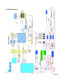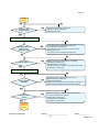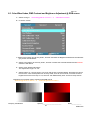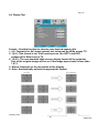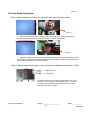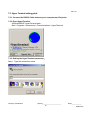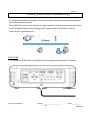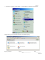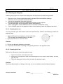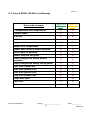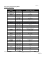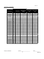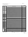
1
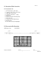
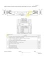
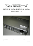
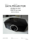
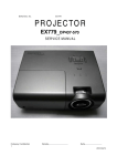
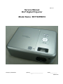
Rev. 00 Service Manual DLP Digital Projector Model Name: EX774/EW674 Company Confidential Optoma_______________________ 1 Delta____________ 2008/07/02 Rev. 00 Revision Rev.00 Description Preliminary Company Confidential Date 07/02/2008 Optoma_______________________ 2 Delta____________ 2008/07/02 Rev. 00 CONTENTS 1.COMPLIANCE OF SAFE REPAIR............................................…….............4 1-1.Cautions During Disassembling And Assembling........…….......4 1-2.Lamp..................……….......................................................4 1-3.Lens............……………............…..........................................4 2 . S P E C I F I C AT I O N S . . . . . . . . . . . . . . … … … … . . . . . . . . . . . . . . . . . . . . . . . . . . . . . . . . . . . . . . . . . . … . . 5 2-1.Summary Specifications.........……………............................................5 2-2.Input/output connectors........………………….........................................6 2-3.Description of Wire Connection....………………......................................7 2-4.Remote Control keypad............………........................................10 2 - 5. C o nt r o l K e y P a d a n d L E D . . . . . . . . … … … … . . . . .. . . . . . . . . . . . . . . . . . . . .. . . . . . . . . .. . 1 2 2-6.BLOCK DIAGRAM..........……................................................13 3.TROUBLE SHOOTING..........………………...............................................14 4.DISASSEMBLY AND ASSEMBLY...........................................................20 5.Firmware..........……………………………………....................................................29 5-1.Projector USB Drivers Installation Guide.................................................29 5-2.DLP Projector Flash-Tool (firmware) User Guide............................….38 5-3.DLP Projector Flash-Tool (splash logo) User Guide........................................42 5-4.Security Timer………………………………...................................................47 5-5.Starting and Shutting down the Projector……………………………………..48 5-6.Setting an Access Password (Security Lock).......................................49 6.Calibration……..……………………………………………………………………..51 6-1.Calibrate Analog RGB.........…….............................................................52 6-2.Calibrate Analog YUV…………………….……………………………………….53 6-3.Color Wheel Index, DMD Contrast and Brightness Adjustment @ RGB source..54 6-4.Display Test……………………..……………..…………………………………….55 6-5.Logo Advanced………………………………………………………………….…..56 6-6.Color Border Adjustment…………………………………………………………..57 7.How To Program By RS232.......……………....................................................58 7-1.RS232 VGA-In Connector…………………………………………………………….58 7-2.RS232 Protocol Function List…………………………………………………….59 7-3.Hyper Terminal setting guide…………….………………………………………….61 8.LAN_RJ45 (RJ45 models only)…………………………………………………………….65 9.Projection Lamp…………………………………………………………………………..70 9-1.R eplac ing the Projection Lamp……………………………………………… 70 9-2.Resetting the Lamp………………………………………………………………71 9-3.Cei ling Ins tallat io n… …… … .……… ………… ………… ………… ………… … 72 10.SERVICE NOTE..........……………………………...................….........................73 10-1.Cleaning...........………………………….........................…...............................73 10-2.Remote Control For Battery Replacement.....……………….........................75 10-3.Power & READY LED Blink Code Message......……………............….….76 10-4.Factory Preset Display Modes...........…………….....................................77 10-5.Spare parts list .................…………........................................................79 10-6.Carton.....................……………...........................................................81 Company Confidential Optoma_______________________ 3 Delta____________ 2008/07/02 Rev. 00 1. COMPLIANCE OF SAFE REPAIR Be sure to read this Service Manual before providing services. In the projector, full consideration is taken to ensure the safety for a fire, electric shock, injury, harmful radiation, and substance. Therefore, observe the notice described in this Service Manual so that the safety is kept when providing services. Moreover, be sure to observe the notice described in the Instruction Manual. Pay attention to the following during service inspection. 1-1. Cautions during disassembling and assembling 1. This equipment contains parts under high voltage. When making repairs, etc. Be sure to pull out the power plug beforehand to insure safety. 2. Parts may be very hot immediately after use. Make sure the equipment has cooled off sufficiently before carrying out repairs. 3. Make sure that parts and screws and wiring, etc. are returned to their original positions. Tube, tape and other insulation materials have been used for safety reasons. The internal wiring has been designed to avoid direct contact with hot parts or parts under high voltage when using clamps or other tools. 4. The parts used in this device have special safety features such as flame-resistance and anti-voltage properties. When replacing parts, always use parts supplied from the factory. 5. After finishing operations make sure that all parts and wires have been returned to their original position and that there has been no deterioration of the area around the location that was worked on. 6. Be sure to use an earth band (wrist band) during repair and inspection. 1-2. Lamp During current conduction, the lamp is in the high-temperature state. In this case, pay careful attention because a high voltage is used. When replacing a lamp, replace it after confirming that the lamp has gotten cold sufficiently. 1-3. Lens Do not look through a lens during projection. This damages your eyes. Company Confidential Optoma_______________________ 4 Delta____________ 2008/07/02 Rev. 00 2. SPECIFICATIONS 2-1. Summary Specifications Model Display type Resolution Color Projection distance Projection screen size Projection lens EX774_DP-3633 EW674_DP-7626 "TI" DMD 12∘, 0.7" x 1, XGA "TI" DMD 12∘, 0.65" X1, WXGA XGA 1024x768 Native WXGA 1280 x 800 Native Graphic: 24-bit 16.7M color (UXGA@60Hz) Video: 27-bit 134M color (1080p) 16-bit 64k 1m to 11.2m 1m to 10m 23.4"~300" 26.68"~307.5" Zoom Lens (manual) Zoom Ratio 1.15:1 Vertical keystone correction +/- 30° Projection methods Front / Rear-Desktop & Front / Rear-Ceiling Data compatibility IBM PC or compatibles (VGA, SVGA, XGA, SXGA, UXGA), Mac SDTV/EDTV/ HDTV 480i/576i, 480p/576p, 720p, 1080i Video compatibility NTSC/NTSC 4.43, PAL/PAL-M/PAL-N,SECAM H-Sync 15, 31~90KHz V-Sync 50 - 85 Hz Safety certification Operation temperature Dimensions / Weight AC Input Power consumption UL, CUL, TUV-GS, CCC, FCC class B, ICES-003, CE Class B, CB, EK, PSB 5~ 40 °C 300mm x 244mm x 100.5mm(8.2 lb) AC Universal 110 ~ 240 @50~60Hz , Typical @110 VAC (100~240)/±10% Typical 350W (standard mode); Typical 300W (ECO mode) Stand By < 5 watts @ 110Vac Lamp Osram E20.6, 280W Audio speaker PC Video Audio 3 w mono speaker (SPL <= 5W) VGA in (Compatible with HDTV component YPbPr / SCART) DVI in (DVI-I connector accept DVI-D and DVI-A signal) Composite video (RCA X 1) S-Video (Mini DIN) Input: R / L (RCA X 2), Mini-Jack X 1 Out: Mini-Jack X 1 USB (USB-B mouse + keypad emulation + Flash upgrade) Control RS-232 (Room Control) RJ45 management (RJ45) Screen Control (12v relay) Security Company Confidential Kensington lock Optoma_______________________ 5 Delta____________ 2008/07/02 Rev. 00 2-2 Input/output connectors Company Confidential Optoma_______________________ 6 Delta____________ 2008/07/02 Rev. 00 2-3. Description Of Wire Connection 2-3-1 Accessories List 1. 2. 3. 4. 5. 6. 7. AC Power Cord x 1 (US 1.8m) Computer Cable VGA to VGA (1.8m) USB Cable, A to B (1.8m) Composite cable RCA * 1 (1.8m) WEEE card Remote Controller with laser pointer Quick start card 8. Carrying case with Optoma Logo 9. Warranty card 10. User's Manual (CD) (23 languages) 2-3-2 Accessories Wire Description USB Cable (1.8m) 308140490X SHELL DRAIN SHELL 4 BLACK 4 3 GREEN 3 2 WHITE 2 1 RED 1 J2 WIRE COLOR J2 WIRE CONNECTION TABLE Company Confidential Optoma_______________________ 7 Delta____________ 2008/07/02 Rev. 00 CABLE SIGNAL D-SUB D-SUB L1800 BLK (RGB CABLE 1.8m) P/N:308140500X Company Confidential Optoma_______________________ 8 Delta____________ 2008/07/02 Rev. 00 CABLE SIGNAL RCA RCA L1800 YEL (1.8m) P/N:308030110X Company Confidential Optoma_______________________ 9 Delta____________ 2008/07/02 Rev. 00 2-4. Remote Control Keypad Company Confidential Optoma_______________________ 10 Delta____________ 2008/07/02 Rev. 00 Company Confidential Optoma_______________________ 11 Delta____________ 2008/07/02 Rev. 00 2-5. Control Key Pad and LED Company Confidential Optoma_______________________ 12 Delta____________ 2008/07/02 Rev. 00 2-6. Block Diagram Company Confidential Optoma_______________________ 13 Delta____________ 2008/07/02 Rev. 00 3. TROUBLE SHOOTING By checking operations during normal usage time, it is possible to carry out judgments on malfunction to a certain extent. Carry out the following checks before disassembling the equipment. Connect the power cord POWER: Light READY : Light Standy-by-ready No • Cable of Power Supply Unit and thermostat Ass’y. • Check the connection of Power Supply (CN201 of Power BD to CN900 of Main BD) • Power Supply Unit malfunction • Check keypad connection Yes Yes Press “power key” POWER: Light READY : OFF Power ON No No Yes POWER: 7 Blinks No POWER: 8 Blinks •Lamp Cover A’ssy is not attached •Switch (CN852) is open No Yes •DMD chip error. •DMD Board PWB Ass’y check. Yes Waiting Power On Company Confidential Optoma_______________________ 14 Delta____________ 2008/07/02 Rev. 00 Turn the power ON Yes The lamp is ON No Yes No •Thermal Break Sensor error •Thermal Break Sensor disconnected. POWER: 4 Blinks No Yes POWER: 5 Blink Lamp does not light:lighting operation sound (ignition sound) exists. • Main Board and Ballast Board Ass’y malfunction • Ballast Connector (CJ4) or LVPS unit (CJ1) or MB(CN530)disconnected • Lamp failure (Lamp is broken, damaged, or burst) No No LAMP:1 Blinks POWER: 6 Blinks • Connector CN800 of Fan disconnected • Lamp fan malfunction • Connector CN801 of Fan disconnected • Ballast fan malfunction Yes LAMP:2 Blinks • Connector CN905 of Fan disconnected • Burner fan malfunction No LAMP:3 Blinks LAMP:4 Blinks • Connector CN802 of Fan disconnected • Burner fan malfunction No POWER: 7 Blinks Yes No No POWER: 9 Blinks No Image Display Company Confidential •Lamp Cover is not attached. •Switch (CN852) is open Yes Lamp does not light:No lighting operation sound (ignition sound) exists. • Flexible cable of Color Wheel Ass’y is disconnected (CN650) or broken. • Color Wheel Ass’y malfunction (does not rotate). • Main Board Ass’y malfunction (Color Wheel Ass’y does not rotate). • Power Supply Unit malfunction. • Index board malfunction (color wheel turns fast). • C/W sensor PWB Ass’y (CN103) / MB PWB (CN850) is disconnected or broken. Optoma_______________________ 15 Delta____________ 2008/07/02 Rev. 00 Image Display No Yes Projector logo screen display No • CW Sensor Board Ass’y malfunction • Main Board Ass’y malfunction • DMD Set malfunction Yes Confirmation with none-signal state No Still dark after the lamp is on for more than 1min Yes • Lamp deterioration (malfunction/usage time) • Power Supply Unit malfunction (No change occurs even after lamp replacement.) • DMD Set malfunction (No change occurs even after lamp replacement.) No No Menu display No Yes • Remote controller set malfunction, Low battery, and outside operation rang • Main Board Ass’y malfunction • Connector (CN451)、(CN101 of IR PWB) disconnected • IR PWB Ass’y malfunction Input each signal No Yes Image display normally No Yes Speaker work normally Yes • Check the pattern generator setting is wrong • Main Board Ass’y malfunction • DMD Set malfunction • Setting on PC side(external output setting, resolution, etc.) • Cable malfunction (disconnection and pins broken) No No • Connector (CN705)、(CN8 of IO BD) disconnected • Connector (CN704) disconnected • Speaker Ass’y malfunction • Main Board Ass’y malfunction • IO Board Ass’y malfunction Check the projection Screen Company Confidential Optoma_______________________ 16 Delta____________ 2008/07/02 Rev. 00 Check the projection Screen Yes Check using all black/white screens with PC connection No Yes Are abnormalities noticeable on projection screen? Yes No No • Black lines on screen (horizontal and vertical) → DMD Set malfunction • Missing pixels (Missing white: 1 or more, missing black: 5 or more, or sequence missing pixels) → DMD Set malfunction • Shadows on screen → Dirt on DMD/projection lens surface • Bluish shadows on corners of screen (during white screen display) → Shifted optical axis of Lens Base Unit Does the lamp go off during operation? Yes No Is LAMP Light again? Yes • Lamp malfunction • Power Supply Unit malfunction No No Over Temp LED: ON Yes • Temperature protector operated due to the increase in temperature based on operating environment • Temperature protector operated due to blocked suction and exhaust holes or dirty fan No System OK Normal operation Company Confidential Optoma_______________________ 17 Delta____________ 2008/07/02 Rev. 00 Image Problems No image appears on-screen Ensure all the cables and power connections are correctly and securely connected as described in the Installation section. Ensure all the pins of connectors are not bent or broken. Check if the projection lamp has been securely installed. Please refer to the Replacing the lamp section. Make sure you have removed the lens cap and the projector is switched on. Partial, scrolling or incorrectly displayed image Press “Re-Sync” on the remote. If you are using a PC: For Windows 95, 98, 2000, XP: 1. Open the My Computer icon, the Control Panel folder, and then double click on the Display icon. 2. Select the Settings tab. 3. Verify that your display resolution setting is lower than or equal to UXGA (1600 x 1200). 4. Click on the Advanced Properties button. If the projector is still not projecting the whole image, you will also need to change the monitor display you are using. Refer to the following steps. 5. Verify the resolution setting is lower than or equal to UXGA(1600 x 1200). 6. Select the Change button under the Monitor tab. 7. Click on Show all devices. Next, select Standard monitor types under the SP box; choose the resolution mode you need under the “Models” box. 8. Verify that the resolution setting of the monitor display is lower than or equal to UXGA (1600 x 1200). (*) If you are using a Notebook: 1. First, follow the steps above to adjust resolution of the computer. 2. Press the toggle output settings. Example: [Fn]+[F4] If you experience difficulty changing resolutions or your monitor freezes, restart all equipment including the projector. Company Confidential Optoma_______________________ 18 Delta____________ 2008/07/02 Rev. 00 The screen of the Notebook or PowerBook computer is not displaying your presentation If you are using a Notebook: Some Notebooks may deactivate their own screens when a second display device is in use. Each has a different way to be reactivated. Refer to your computer’s manual for detailed information. Image is unstable or flickering Use Phase to correct it. Change the monitor color setting on your computer. Image has vertical flickering bar Use Frequency to make an adjustment. Check and reconfigure the display mode of your graphic card to make it compatible with the projector. Image is out of focus Make sure the lens cap is removed. Adjusts the Focus Ring on the projector lens. Make sure the projection screen is between the required distances from the projector. The image is stretched when displaying 16:9 DVD title When you play anamorphic DVD or 16:9 DVD, the projector will show the best image in 16:9 format on projector side. If you play 4:3 format DVD title, please change the format as 4:3 in projector OSD.If the image is still stretched, you will also need to adjust the aspect ratio by referring to the following: Please setup the display format as 16:9 (wide) aspect ratio type on your DVD player. Image is too small or too large Adjust the Zoom Ring on the top of the projector. Move the projector closer to or further from the screen. Press [Menu] button on the remote control or projector panel, go to Display | Format and try the different settings. Image has slanted sides If possible, reposition the projector so that it is centered on the screen and below the bottom of the screen. Press [Keystone +/-] button until the sides are vertical on the remote control. Image is reversed Select Setup | Projection from the OSD and adjust the projection direction. Intermission Problems The projector stops responding to all controls If possible, turn off the projector, then unplug the power cord and wait at least 60 seconds before reconnecting power. Lamp burns out or makes a popping sound When the lamp reaches its end of life, it will burn out and may make a loud popping sound. If this happens, the projector will not turn on until the lamp module has been replaced. Company Confidential Optoma_______________________ 19 Delta____________ 2008/07/02 Rev. 00 4. DISASSEMBLY AND ASSEMBLY Removing the Lamp Module and Lamp Cover Look at Top Case side. Loose the two screws. Open the lamp cover. Loose the two screws and then take out the lamp module by the ring-pull. Lamp module views. Lamp holder views. Company Confidential Optoma_______________________ 20 Delta____________ 2008/07/02 Rev. 00 Removing the Top Cover Remove the two screws and take off the top case frame. Remove these the eight screws. Loose the two screws. Company Confidential Then remove the top cover. Optoma_______________________ 21 Delta____________ 2008/07/02 Rev. 00 Removing the KeyPad / Front Cover / Main Board Remove these the six screws. View of the IO Cover. Remove these the nine screws. Remove the three screws. Open the shield. Company Confidential Optoma_______________________ 22 Delta____________ 2008/07/02 Rev. 00 Removing the Main Board & IO Board Fan4 – CN802 Keypad – CN452 Power – CN900 SPK – CN704 Fan2 – CN801 LAMP – CN530 Fan1 – CN800 Fan3 – CN905 IR2 – CN451 INDEX – CN850 CW – CN650 Thermal – CN852 Company Confidential Optoma_______________________ 23 Delta____________ 2008/07/02 Rev. 00 Disassemble the Main Board & IO Board 2 1 Remove the two screws. Disconnect this cable and remove the Main Board & IO Board assy. Remove the two screws & nuts. Remove the six hexagonal bolts The main BD view Company Confidential Optoma_______________________ 24 Delta____________ 2008/07/02 Rev. 00 Disassemble the IO Board & bracket Remove the two screws & hexagonal bolts Views of the IO BD Remove these the seven screws Check this place when you assemble the cover. Remove the bracket. Company Confidential Optoma_______________________ 25 Delta____________ 2008/07/02 Rev. 00 Disassemble the Ballast and Fan Assy. Check this place when you assemble the wire. Remove this screw. The Lamp Driver. Company Confidential Remove this screw. Remove the Lamp Driver. Remove the screws. Optoma_______________________ 26 Delta____________ 2008/07/02 Rev. 00 Disassemble the Fan and Optic Engine Assy. Remove the Fan. The Fan Module. Remove these the two screws. Take the heat-sink away. Remove these the three screws. Remove Optic Engine Assy. Company Confidential Optoma_______________________ 27 Delta____________ 2008/07/02 Rev. 00 Disassemble the Optic Engine Assy and Power Assy . View Optic Engine Assy. View Optic Engine Assy. pull pull Remove Optic Engine Assy. Remove the two Fan Assy. Remove these the four screws. Check this screw when you assemble the wire. Company Confidential Optoma_______________________ 28 Delta____________ 2008/07/02 Rev. 00 5. Firmware 5-1 Projector USB Drivers Installation Guide NOTE: The user must have administrative privileges on the target computer in order to install your driver. The installation target directory must not write protected. Attention: This utility is for DDP2000/2030 series projector only. Ver 5.0 System Requirement IBM compatible PC. Windows XP-SP2 Operator may need basic knowledge of Windows device installation. Install Flash-Tool to PC Run the “Digital Zoom Projector Flash Tool Vx.y.msi”, it will automatically launch the USB drivers update. Following are the dialogues of the Driver Install process… This is the first page of install dialog. This is the driver installation destination dialogue, use “Change” button to override the default directory if you decide to put it into different place. Company Confidential Optoma_______________________ 29 Delta____________ 2008/07/02 Rev. 00 Ready to install the drivers into the PC, press <Install> to start. The Installer copies the necessary files to PC. Launch the driver update Press the <Finish> button with the Launch checkbox checked, the wizard will start the INF update. Note: The INF update may take a while depends your computer speed and INF numbers… Be patient! These windows will automatically close after the updating finished. Company Confidential Optoma_______________________ 30 Delta____________ 2008/07/02 Rev. 00 The install program copy the new INF into Windows directory, it will search the old INF and replace it with the newer one. Remove the USB cable between PC and projector if it is connected. The WinDrive USB drivers will be installed and registered to system. After the driver install, a test application will start automatically with Windows hardware wizard for all necessary USB driver. The driver test launched, wait for the key stroke to enter Projector Control mode… Connect the USB cable now! If the driver test application does not launch automatically, run the “Launch FlashToolBL.exe” from installed short cut at Program> Digital Zoom Projector> projector flashtool version 5> Launch FlasToolBL.exe Company Confidential Optoma_______________________ 31 Delta____________ 2008/07/02 Rev. 00 Make sure the USB cable is firmly attached between projector and computer; the power switch is in ON position and projector is in STAND BY mode. Press <Down>, <Up>, <Right>, <Up> key in sequence on keypad (DP16/DP18/DP3622 series) or IR remote controller (DP02 series)。 The power and lamp LED will blink and the Projector Control mode will be enabled. The New Hardware Wizard launched at the first time Windows detects a new USB device attached. Use the recommended suggestion usually works all the way in the process. (Select “No, not this time”; Press the Next) (Windows XP-SP2) (Press the Next) Windows detected and updating the USB Projector Control driver. Company Confidential Optoma_______________________ 32 Delta____________ 2008/07/02 Rev. 00 Windows completed the new hardware wizard. Press Finish to end the Wizard. Note: In case you got USB enumeration problem, the USB no longer recognize your projector! Please clear the USB items in the windows registry and install the Flashtool USB driver again. (Ref: Appendix-A) Once the Projector Control USB driver enumerated; the projector information displays in the status pane. Press the <Check> button will drive the projector turns into Flashtool mode. This is verifying that if the projector will switch to Flashtool mode or not! The projector is switching to Flashtool mode after click the <Check>… Company Confidential Optoma_______________________ 33 Delta____________ 2008/07/02 Rev. 00 The Windows New Hardware Wizard will launch again for the second USB Projector Control. (Select “No, not this time”; Press the Next) ( Windows XP-SP2) Follow the recommended options and process the driver installation. (Press the Next) Wizard copies the necessary files and updates the driver. Windows New Hardware Wizard launches for the Projector Flashtool USB device. (Select “No, not this time”; Press the Next) (Windows XP-SP2) Company Confidential Optoma_______________________ 34 Delta____________ 2008/07/02 Rev. 00 Follow the recommended options and process the driver installation. (Press the Next) Wizard copies the necessary files and updates the driver. Flashtool USB driver installed. Press Finish to end the Wizard. Congratulations! Power off the projector now, your driver has been checked and works for Flashtool. Company Confidential Optoma_______________________ 35 Delta____________ 2008/07/02 Rev. 00 Appendix-A How to clear the USB enumeration registry? Run “regedit” and select the following items HKEY_LOCAL_MACHINE->SYSTEM->CurrentControlSet->Enum->USB-> The DP3633 series The DP7626 series VID_1501&Pid_3633xxx VID_1501&Pid_7626xxx Press <Delete> and remove these registries. (You need the read/write privilege of the Windows registry to delete it. Select the item and click right mouse will lead you to the Permissions dialog for applying the security options) Company Confidential Optoma_______________________ 36 Delta____________ 2008/07/02 Rev. 00 Appendix-B Projector USB status on Windows Device Manager The USB HID device will be installed automatically via Windows' USB hot-plug mechanism. The Projector Control will be dynamically installed after entering the maintenance mode (Hit key sequence as <down>, <up>, <right>, <up>); The Projector Flashtool will be dynamically installed when starting the flash upgrading by Flashtool or FlashtoolBL utility. The WIndriver is the root driver for both Projector Control and Flashtool. Company Confidential Optoma_______________________ 37 Delta____________ 2008/07/02 Rev. 00 5-2 DLP Projector Flash-Tool (firmware) User Guide Ver 5.0 NOTE: The user must have administrative privileges on the target computer in order to install your driver. The installation target directory must not write protected. Attention: This utility is for DLP DDP2000/3020 series projector only. System Requirement: . IBM compatible PC. . Windows XP operating system (English). . Operator must have basic knowledge of Windows device installation. . Projector Flashtool USB driver installed. Install Flash-Tool to PC Run the “Digital Zoom Projector Flash Tool Vx.y.msi”, if your projector USB drivers not installed yet! Check the USB driver installation guide about the how-to. Flash-Tool User’s Guide (upgrading projector firmware) Step 1: Launch the “FlashTool.exe” from installed short-cut at Program > Digital Zoom Projector> Launch FlasTool.exe or click the “Lauch FlashTool.exe” shortcut icon on the desktop. Company Confidential Optoma_______________________ 38 Delta____________ 2008/07/02 Rev. 00 Step 2: Following is the screen capture when there is no projector connected. Step 3: Make sure the USB cable is firmly attached between projector and computer; the power switch is in ON position (if the projector got hardware power switch) and projector is in STAND BY mode. Press <Down>, <Up>, <Right>, <Up> key in sequence on keypad (DP2601/2618/3618 series) or IR remote controller (DP3602 series)。 The power and lamp LED will blink and the Flash-Tool mode will be enabled. Press “Choose” to select file Projector information Note: The Windows hardware wizard will pop up if the USB device driver is not installed. Just select . the recommended options and let Windows Wizard do it automatically… Step 4: Press “Choose” button to locate the new firmware which can be downloaded from websit e (for example: DP3635-JAXX-DPD0A.img). Select the candidate .img file and either double click it or press the “Open” button to load the file. Company Confidential Optoma_______________________ 39 Delta____________ 2008/07/02 Rev. 00 Use img file type for firmware binary data Step 4-1:.The Flashtool will validate the signature of the binary image file for upgrading. The “Start” button will not enable if the binary image is not a valid projector firmware. The “Start” button Step 5: Press “Start” button to start flash the firmware into projector, the warning message box will appear to get your confirmation. Press <OK> to continue. Step 6: The last warning message box appears, this is the last chance to stop the update, press “OK” button to start the firmware update. Company Confidential Optoma_______________________ 40 Delta____________ 2008/07/02 Rev. 00 Caution: DO NOT install any USB driver when erasing or upgrading process started. Step 7: By the Flash technology, the old firmware needs to be erased first. Flash-Tool will automatically erase the old firmware before upgrading. Erasing status Caution: DO NOT install any USB driver when erasing or upgrading process started. Step 8: After old firmware erased, the new firmware upgrading process will start. Upgrading new firmware Company Confidential Optoma_______________________ 41 Delta____________ 2008/07/02 Rev. 00 Step 9: After the new firmware upgraded, the Flash-Tool will perform the final validation. The dialog showed checksum with verification message! Checksum verified Step 10: Done! Power off the projector. 5-3 DLP Projector Flash-Tool (splash logo) User Guide NOTE: The user must have administrative privileges on the target computer in order to install your driver. The installation target directory must not write protected. Attention: This utility is for DLP DDP2000/3020 series projector only. Ver 5.0 System Requirement: . IBM compatible PC. . Windows XP operating system (English). . Operator must have basic knowledge of Windows device installation. . Projector Flashtool USB driver installed. Install Flash-Tool to PC Run the “Digital Zoom Projector Flash Tool Vx.y.msi”, if your projector USB drivers are not installed yet! Check the USB driver installation guide about the how-to. Company Confidential Optoma_______________________ 42 Delta____________ 2008/07/02 Rev. 00 Flash-Tool User’s Guide (upgrading projector logo) Step 1: Launch the “FlashTool.exe” from installed short-cut at Program > Digital Zoom Projector> Launch FlasTool.exe or click the “Lauch FlashTool.exe” shortcut icon on the desktop. Step 2: Following is the screen capture when there is no projector connected. Step 3: Make sure the USB cable is firmly attached between projector and computer; the power switch is in ON position (if the projector got hardware power switch) and projector is in STAND BY mode. Press <Down>, <Up>, <Right>, <Up> key in sequence on keypad (DP2601/2618/3618 series) or IR remote controller (DP3602 series)。 The power and lamp LED will blink and the Flash-Tool mode will be enabled. Company Confidential Optoma_______________________ 43 Delta____________ 2008/07/02 Rev. 00 Press “Choose” to select file Projector information Note: . The Windows hardware wizard will pop up if the USB device driver is not installed. Just select the recommended options and let Windows Wizard do it automatically… Step 4: Press “Choose” button and select either BMP or JPG in the “File of type” option. BMP/JPG selection Step 4-1: Double click the logo file or use open button to select the logo you want. Step 4-2:.The Flashtool will validate the size of the logo file. Logo will be converted to RLE format and stored to the projector’s flash memory. The compressed RLE size can not exceed the flash memory limitation. In case of the size problem, try to reduce the colors by select the JPEG colors option in the tool. (Valid only for JPEG files) Company Confidential Optoma_______________________ Delta____________ 44 2008/07/02 Rev. 00 JPEG color selection Step 5: Press “Start” button to start flash the firmware into projector, the warning message box will appear to get your confirmation. Press <OK> to continue. Step 6: The last warning message box appears, this is the last chance to cancel the update, press “OK” button to start the logo change. Caution: DO NOT install any USB driver when erasing or upgrading process started. Company Confidential Optoma_______________________ 45 Delta____________ 2008/07/02 Rev. 00 Step 7: By the Flash-ROM technology, Flash-Tool need to erase the old logo data before it can change it. Erasing old logo Caution: DO NOT install any USB driver when erasing or upgrading process started Step 8: After old logo erased, the new logo upgrading process will start. Changing new logo Step 9: After the new logo changed, the Flash-Tool will perform the final validation. The dialog showed checksum with verification message! Checksum verified Step 10: Done! Power off the projector. Company Confidential Optoma_______________________ 46 Delta____________ 2008/07/02 Rev. 00 5-4.Security Timer to move to the SETUP menu. Press Press the Menu button to open the OSD menu. Press to move up and down and select Security. Press to move up and down and select to change Security Timer. Press Enter to open the Security Timer submenu. Press values for settings, and then press Enter to confirm the new setting. ITEM DESCRIPTION DEFAULT Month Set the number of months the projector can be used. 0 Day Set the number of days for the projector to be active. 0 Hour Set the number of hours for the projector to be active. 0 Company Confidential Optoma_______________________ 47 Delta____________ 2008/07/02 Rev. 00 5-5.Starting and Shutting down the Projector 1. Connect the power cord to the projector. 2. Turn On the connected devices. Ensure the Power LED is steady (flashing) and then press the Power button to turn On the projector. 3. The projector splash screen displays and connected devices are detected. If the connected device is a PC, press the appropriate keys on the computer keyboard to switch the display output to the projector. (Check the user manual of the PC to determine the appropriate Fn key combination to change display output.) 4. If more than one input device is connected, press the Source button repeatedly to switch among devices. (DVD and HDTV are supported through the VGA connector) 5. To turn off the projector, press the power button. The Power Off? / Press Power again message appears. Press the Power button again to turn off the projector. Caution: Do not unplug the power cord until the Lamp LED (on Cooling mode) stops flashing–indicating the projector has cooled down. Company Confidential Optoma_______________________ 48 Delta____________ 2008/07/02 Rev. 00 5-6.Setting an Access Password (Security Lock) You can use the Remote digital buttons to set a password and prevent unauthorized use of the projector. When enabled, the password must be entered after you power on the projector. Keep the password in a safe place. Without the password, you will not be able to use the projector. If you lose the password, contact your reseller for information on clearing the password. 1. Press the Menu button to open the OSD menu. 2. Press ◄► to move to the SETUP menu. Company Confidential Optoma_______________________ 49 Delta____________ 2008/07/02 Rev. 00 3. Select the Security and then press Enter to enter to the Sub-Menu. 4. Press ▲▼ to select Security Setting and then press ◄► to select Enable/Disable. 5. When the security setting is Enabled, you are prompted to enter a password soon after the projector is powered on. Note: If the incorrect password is entered three times the projector auto shutdowns down after 10 seconds. The default password is: <1> <2> <3> <4> <5>. 6. To change a password, enter the previous password when prompted. Use the following keys <1>, <2>, <3>, <4>, <5>, <6>, <7>, <8>, <9> to define a new password. Company Confidential Optoma_______________________ 50 Delta____________ 2008/07/02 Rev. 00 6. Calibration Step of into Service Mode . Step 1: To turn on the projector, press the Power button on the keypad or IR controller, Until the “Power Off? Press Power again” message appears. Step 2:Then press “Left”=>“Right”=>“Down”=>“Up” button on the keypad or IR controller. Step 3:If password is correct then go into Service Mode. Company Confidential Optoma_______________________ 51 Delta____________ 2008/07/02 Rev. 00 6-1. Calibrate Analog RGB (EP774: 1024 x 768 @ 60Hz & EW674:1280x800@60Hz): Step 1: In Service 1Mode select ADC Calibration - VGA In this menu input pattern with White (240,240,240) and Black (16,16,16) for calibrate VGA Source. After input ready press “Enter” key to calibration. Input Pattern Step 2: After complete the OSD will show the picture as follow, if not complete, just close the OSD. Note: Offset & Gain Value Default After ADC Offset 511 Gain 511 Step 3: Compare internal white pattern and RGB source white pattern, if the brightness gap ratio of these two source is bigger than 3.5%. Company Confidential Optoma_______________________ Delta____________ 52 2008/07/02 Rev. 00 6-2. Calibrate Analog YUV Equipment: VG828, must be take off H/V sync terminal from machine. Step 1: In Service 1 Mode select ADC Calibration - YUV. In this menu input pattern with 75﹪SMPTE pattern for calibrate YUV Source and notice that the input source must be 480i format . After input ready press “Enter” key to proceed. Input Pattern Step 2: After complete the OSD will show the picture as follow, if not complete, just close the OSD. NOTE: You can select Calibration Status – VGA or Calibration Status – YUV item to watch the calibrated value at any time. Company Confidential Optoma_______________________ Delta____________ 53 2008/07/02 Rev. 00 6-3. Color Wheel Index, DMD Contrast and Brightness Adjustment @ RGB source A. Switch Timing to ”1024x768 @ 60HZ” for EX774 & “1280*800”for EW674. B. In Service 1mode. C. Switch to the Pattern 48 “32 Gray Scale”, and then decrease the Brightness Default Diff until all black gray scales are still distinct. D. Switch to the Pattern 48 “32 Gray Scale”, and then increase the Contrast Default Diff until all white scales are still distinct. E. Select “Color Wheel Index Delay”. The adjustment range is 0~719. F. Switch Pattern 47 “16 Gray Scale”. Fine-tune until the gray scale still distinct. Decrease the color to the minimum. Then switch pattern 48 “32 Gray Scale”, tune off G, B channel, check the smooth in brighter level of the R 32 ramp. If not, fine tune “CW INDEX Delay Time” until R 32 ramp smooth. Brightness and Contrast need to measure with RGB source ”1024x768 @ 60Hz” for EX774 & “1280*800 @ 60Hz”for EW674. Company Confidential Optoma_______________________ 54 Delta____________ 2008/07/02 Rev. 00 6-4. Display Test Format - Use this function to choose your desired aspect ratio. 1. 4:3: Format is for 4x3 input sources not enhanced for Wide screen TV. 2. 16:9 I: This format is for 16x9 input sources, like HDTV and DVD enhanced for Wide screen TV. 4. 16:9 II: The non-standard wide-screen display format of the projector. Part of the original image will be cut if the image aspect ratio is less than 1.67:1. 5. Native: Depends on the resolution of the display. 6. Auto: Automatically selects the appropriate format. Company Confidential Optoma_______________________ 55 Delta____________ 2008/07/02 Rev. 00 6-5. Logo Advanced Logo Select the screen to display during startup. Optoma—the supplied default startup screen. User—customized screen capture using the Logo Capture function. Logo Capture Capture a displayed screen to use as the startup screen. 1. Display the desired screen on the projector. 2. Select Logo Capture from the Advanced menu. A confirmation screen displays. 3. Select OK. Screen capture in progress. Screen capture succeeded displays. The captured screen is saved as User in the Logo menu. Company Confidential Optoma_______________________ 56 Delta____________ 2008/07/02 Rev. 00 6-6.Color Border Adjustment Step 1: Adjust integration rod screw to eliminate color edge @ White pattern. Screw 1 1. Adjust the hexagonal screw in order to right and left side color border disappeared. (Enable just disappearing of left side color border on the full white pattern). Screw 2 2. Adjust the hexagonal screw in order to up and down side color border disappeared. By the color border is margin value on the down side of full white pattern. (Enable just disappearing of down side color border on the full white pattern) Step 2: Adjust lamp module angle to set the maximum brightness measured by CL200. => Adjusted screw. => Fixed screw. Loosed the fixed screw, CL200 is putted on the left corner of the screen(When full set is putted upside down), to adjust the adjusted screw gets the highest luminance value then fixed the screw in the moment. Company Confidential Optoma_______________________ 57 Delta____________ 2008/07/02 Rev. 00 7. How To Program By RS232 7-1. RS232 VGA-In Connector Pin No Name I/O (From Projector Side) 1 NC __ 2 RXD IN 3 TXD OUT 4 NC __ 5 NC __ 6 NC __ 7 RS232 RTS 8 RS232 CTS 9 NC __ Company Confidential Optoma_______________________ 58 Delta____________ 2008/07/02 Rev. 00 7-2. RS232 Protocol Function List RS232 Commands SEND to projector Baud Rate : 9600 Data Bits: 8 Parity: None Stop Bits: 1 Flow Control None UART16550 FIFO: Disable Projector Return (Pass): P Projector Return (Fail): F XX=01-99, projector’s ID XX=00 is for all projectors Company Confidential Note: There is a <CR> after all ASCII commands 0D is the HEX code for <CR> in ASCII code ----------------------------------------------------------------------------------------------------------------------------------------------------------------------------------------232 ASCII Code HEX Code Function Description ----------------------------------------------------------------------------------------------------------------------------------------------------------------------------------------~XX00 1 7E 30 30 30 30 20 31 0D Power ON ~XX00 2 7E 30 30 30 30 20 32 0D Power OFF ----------------------------------------------------------------------------------------------------------------------------------------------------------------------------------------~XX01 1 7E 30 30 30 31 20 31 0D Resync ~XX02 1 7E 30 30 30 32 20 31 0D AV Mute On ~XX02 2 7E 30 30 30 32 20 32 0D Off ~XX04 1 7E 30 30 30 34 20 31 0D Freeze ~XX04 2 7E 30 30 30 34 20 32 0D Unfreeze ~XX11 1 7E 30 30 31 31 20 31 0D IR Function On ~XX11 2 7E 30 30 31 31 20 32 0D Off ~XX12 2 7E 30 30 31 32 20 32 0D DVI-D ~XX12 3 7E 30 30 31 32 20 33 0D DVI-A ~XX12 5 7E 30 30 31 32 20 35 0D VGA ~XX12 7 7E 30 30 31 32 20 37 0D Direct Source Selection VGA SCART ~XX12 8 7E 30 30 31 32 20 38 0D VGA Component ~XX12 9 7E 30 30 31 32 20 39 0D S-video ~XX12 10 7E 30 30 31 32 20 31 30 0D Video ----------------------------------------------------------------------------------------------------------------------------------------------------------------------------------------~XX20 1 7E 30 30 32 30 20 31 0D Display Mode Presentation ~XX20 2 7E 30 30 32 30 20 32 0D Bright ~XX20 3 7E 30 30 32 30 20 33 0D Movie ~XX20 4 7E 30 30 32 30 20 34 0D sRGB ~XX20 5 7E 30 30 32 30 20 35 0D User 1 ~XX20 6 7E 30 30 32 30 20 36 0D User 2 ----------------------------------------------------------------------------------------------------------------------------------------------------------------------------------------~XX21 n 7E 30 30 32 31 20 a 0D Brightness n= -50 (a=2D 35 30) - +50 (a=35 30) ~XX22 n 7E 30 30 32 32 20 a 0D Contrast n= -50 (a=2D 35 30) - +50 (a=35 30) ~XX23 n 7E 30 30 32 33 20 a 0D Sharpness n= -15 (a=2D 31 35) - +15 (a=31 35) ~XX44 n 7E 30 30 34 34 20 a 0D Saturation n= -50 (a=2D 35 30) - +50 (a=35 30) ~XX45 n 7E 30 30 34 35 20 a 0D Tint n= -50 (a=2D 35 30) - +50 (a=35 30) ----------------------------------------------------------------------------------------------------------------------------------------------------------------------------------------~XX24 n 7E 30 30 32 34 20 a 0D Color Red Gain n= -50 (a=2D 35 30) - +50 (a=35 30) ~XX25 n 7E 30 30 32 35 20 a 0D Green Gain n= -50 (a=2D 35 30) - +50 (a=35 30) ~XX26 n 7E 30 30 32 36 20 a 0D Blue Gain n= -50 (a=2D 35 30) - +50 (a=35 30) ~XX27 n 7E 30 30 32 37 20 a 0D Red Bias n= -50 (a=2D 35 30) - +50 (a=35 30) ~XX28 n 7E 30 30 32 38 20 a 0D Green Bias n= -50 (a=2D 35 30) - +50 (a=35 30) ~XX29 n 7E 30 30 32 39 20 a 0D Blue Bias n= -50 (a=2D 35 30) - +50 (a=35 30) ~XX30 n 7E 30 30 33 30 20 a 0D Cyan n= -50 (a=2D 35 30) - +50 (a=35 30) ~XX31 n 7E 30 30 33 31 20 a 0D Yellow n= -50 (a=2D 35 30) - +50 (a=35 30) ~XX32 n 7E 30 30 33 32 20 a 0D Magenta n= -50 (a=2D 35 30) - +50 (a=35 30) ~XX33 1 7E 30 30 33 33 20 31 0D Reset ----------------------------------------------------------------------------------------------------------------------------------------------------------------------------------------~XX34 n 7E 30 30 33 34 20 a 0D White Peaking n= 0 (a=30) – 10 (a=31 30) ~XX35 1 7E 30 30 33 35 20 31 0D Degamma Film ~XX35 2 7E 30 30 33 35 20 32 0D Video ~XX35 3 7E 30 30 33 35 20 33 0D Graphics ~XX35 4 7E 30 30 33 35 20 34 0D PC ----------------------------------------------------------------------------------------------------------------------------------------------------------------------------------------~XX36 1 7E 30 30 33 36 20 31 0D Color Temp. Warm ~XX36 2 7E 30 30 33 36 20 32 0D Medium ~XX36 3 7E 30 30 33 36 20 33 0D Cold ~XX37 1 7E 30 30 33 37 20 31 0D Color Space Auto ~XX37 2 7E 30 30 33 37 20 32 0D RGB ~XX37 3 7E 30 30 33 37 20 33 0D YUV ----------------------------------------------------------------------------------------------------------------------------------------------------------------------------------------~XX39 2 7E 30 30 33 39 20 32 0D Input Source DVI-I ~XX39 5 7E 30 30 33 39 20 35 0D VGA ~XX39 9 7E 30 30 33 39 20 39 0D S-Video ~XX39 10 7E 30 30 33 39 20 31 30 0D Video ~XX40 1 7E 30 30 34 30 20 31 0D De-interlace On ~XX40 2 7E 30 30 34 30 20 32 0D Off ----------------------------------------------------------------------------------------------------------------------------------------------------------------------------------------~XX60 1 7E 30 30 36 30 20 31 0D Format 4:3 ~XX60 2 7E 30 30 36 30 20 32 0D 16:9-l ~XX60 3 7E 30 30 36 30 20 33 0D 16:9-ll/16 :10 ~XX60 5 7E 30 30 36 30 20 35 0D Natvie ~XX60 7 7E 30 30 36 30 20 37 0D Auto ----------------------------------------------------------------------------------------------------------------------------------------------------------------------------------------~XX61 n 7E 30 30 36 31 20 a 0D Overscan n= 0 (a=30) – 10 (a=31 30) ~XX62 n 7E 30 30 36 32 20 a 0D Zoom n= -30 (a=2D 33 30) - +50 (a=35 30) ~XX63 n 7E 30 30 36 33 20 a 0D H Image Shift n= -50 (a=2D 35 30) - +50 (a=35 30) ~XX64 n 7E 30 30 36 34 20 a 0D V Image Shift n= -24 (a=2D 32 34) - +24 (a=32 34) ~XX66 n 7E 30 30 36 36 20 a 0D V Keystone n= -30 (a=2D 33 30) - +30 (a=33 30) ----------------------------------------------------------------------------------------------------------------------------------------------------------------------------------------~XX70 1 7E 30 30 37 30 20 31 0D Language English ~XX70 2 7E 30 30 37 30 20 32 0D German ~XX70 3 7E 30 30 37 30 20 33 0D French ~XX70 4 7E 30 30 37 30 20 34 0D Italian ~XX70 5 7E 30 30 37 30 20 35 0D Spanish ~XX70 6 7E 30 30 37 30 20 36 0D Portuguese ~XX70 7 7E 30 30 37 30 20 37 0D Polish ~XX70 8 7E 30 30 37 30 20 38 0D Dutch ~XX70 9 7E 30 30 37 30 20 39 0D Swedish ~XX70 10 7E 30 30 37 30 20 31 30 0D Norwegian/Danish ~XX70 11 7E 30 30 37 30 20 31 31 0D Finnish ~XX70 12 7E 30 30 37 30 20 31 32 0D Greek ~XX70 13 7E 30 30 37 30 20 31 33 0D Traditional Chinese ~XX70 14 7E 30 30 37 30 20 31 34 0D Simplified Chinese ~XX70 15 7E 30 30 37 30 20 31 35 0D Japanese ~XX70 16 7E 30 30 37 30 20 31 36 0D Korean ~XX70 17 7E 30 30 37 30 20 31 37 0D Russian ~XX70 18 7E 30 30 37 30 20 31 38 0D Hungarian ~XX70 19 7E 30 30 37 30 20 31 39 0D Czechoslovak ~XX70 20 7E 30 30 37 30 20 32 30 0D Arabic ~XX70 21 7E 30 30 37 30 20 32 31 0D Thai Turkish ~XX70 22 7E 30 30 37 30 20 32 32 0D ----------------------------------------------------------------------------------------------------------------------------------------------------------------------------------------- Optoma_______________________ 59 Delta____________ 2008/07/02 Rev. 00 ----------------------------------------------------------------------------------------------------------------------------------------------------------------------------------------~XX71 1 7E 30 30 37 31 20 31 0D Projection Front-Desktop ~XX71 2 7E 30 30 37 31 20 32 0D Rear-Desktop ~XX71 3 7E 30 30 37 31 20 33 0D Front-Ceiling ~XX71 4 7E 30 30 37 31 20 34 0D Rear-Ceiling ----------------------------------------------------------------------------------------------------------------------------------------------------------------------------------------~XX72 1 7E 30 30 37 32 20 31 0D Menu Location Top Left ~XX72 2 7E 30 30 37 32 20 32 0D Top Right ~XX72 3 7E 30 30 37 32 20 33 0D Center ~XX72 4 7E 30 30 37 32 20 34 0D Bottom Left ~XX72 5 7E 30 30 37 32 20 35 0D Bottom Right ----------------------------------------------------------------------------------------------------------------------------------------------------------------------------------------~XX73 n 7E 30 30 37 33 20 a 0D Signal Frequency n= 0 (a=30) – 31 (a=33 31) ~XX74 n 7E 30 30 37 34 20 a 0D Phase n= -5 (a=2D 35) - +5 (a=35) ~XX75 n 7E 30 30 37 35 20 a 0D H. Position n= -5 (a=2D 35) - +5 (a=35) ~XX76 n 7E 30 30 37 36 20 a 0D V. Position n= -5 (a=2D 35) - +5 (a=35) ----------------------------------------------------------------------------------------------------------------------------------------------------------------------------------------~XX77 n 7E 30 30 37 37 20 aabbcc 0D Security Security Timer Hour /Day/ Month n=hhddmm hh= 0 (a=30) ~ 24 (a=32 34) dd= (a=30) ~ 30 (a=33 30) mm= 0 (a=30) ~ 12 (a=31 32) ~XX78 1 7E 30 30 37 38 20 31 0D Security Settings Enable ~XX78 2 7E 30 30 37 38 20 32 0D Disable ----------------------------------------------------------------------------------------------------------------------------------------------------------------------------------------~XX79 n 7E 30 30 37 39 20 a 0D Projector ID n=0 (a=30)- 99 (a=39 39) ----------------------------------------------------------------------------------------------------------------------------------------------------------------------------------------~XX80 1 7E 30 30 38 30 20 31 0D Mute On ~XX80 2 7E 30 30 38 30 20 32 0D Off 7E 30 30 38 31 20 a 0D Volume n= 0 (a=30) – 10 (a=31 30) ~XX81 n ~XX89 1 7E 30 30 38 39 20 31 0D Audio Input Mini Jack ~XX89 1 7E 30 30 38 39 20 32 0D RCA ----------------------------------------------------------------------------------------------------------------------------------------------------------------------------------------~XX82 1 7E 30 30 38 32 20 31 0D Logo Optoma ~XX82 2 7E 30 30 38 32 20 32 0D User ~XX83 1 7E 30 30 38 33 20 31 0D Logo capture ~XX88 1 7E 30 30 38 34 20 31 0D Close Caption On ~XX88 2 7E 30 30 38 34 20 32 0D Off ----------------------------------------------------------------------------------------------------------------------------------------------------------------------------------------~XX86 1 7E 30 30 38 36 20 31 0D RS232 RS232 ~XX86 2 7E 30 30 38 36 20 32 0D Network ----------------------------------------------------------------------------------------------------------------------------------------------------------------------------------------~XX100 1 7E 30 30 31 30 30 20 31 0D Source Lock On ~XX100 2 7E 30 30 31 30 30 20 32 0D Off ~XX101 1 7E 30 30 31 30 31 20 31 0D High Altitude On ~XX101 2 7E 30 30 31 30 31 20 32 0D Off ~XX102 1 7E 30 30 31 30 32 20 31 0D Information Hide On ~XX102 2 7E 30 30 31 30 32 20 32 0D Off ~XX103 1 7E 30 30 31 30 33 20 31 0D Keypad Lock On ~XX103 2 7E 30 30 31 30 33 20 32 0D Off ----------------------------------------------------------------------------------------------------------------------------------------------------------------------------------------~XX104 1 7E 30 30 31 30 34 20 31 0D Background Color Blue ~XX104 2 7E 30 30 31 30 34 20 32 0D Black ~XX104 3 7E 30 30 31 30 34 20 33 0D Red ~XX104 4 7E 30 30 31 30 34 20 34 0D Green ~XX104 5 7E 30 30 31 30 34 20 35 0D White ----------------------------------------------------------------------------------------------------------------------------------------------------------------------------------------~XX105 1 7E 30 30 31 30 35 20 31 0D Advanced Direct Power On On ~XX105 2 7E 30 30 31 30 35 20 32 0D Off ~XX106 n 7E 30 30 31 30 36 20 a 0D Auto Power Off (min) n=0 (a=30)-120 (a=31 32 30) (multiple of 5) ~XX107 n 7E 30 30 31 30 37 20 a 0D Sleep Timer (min) n=0 (a=30)-900 (a=39 30 30) (multiple of 5) ----------------------------------------------------------------------------------------------------------------------------------------------------------------------------------------~XX108 1 7E 30 30 31 30 38 20 31 0D Lamp Setting Lamp Hour ~XX109 1 7E 30 30 31 30 39 20 31 0D Lamp Reminder On ~XX109 2 7E 30 30 31 30 39 20 32 0D Off ~XX110 1 7E 30 30 31 31 30 20 31 0D Brightness Mode Bright ~XX110 2 7E 30 30 31 31 30 20 32 0D STD ~XX111 1 7E 30 30 31 31 31 20 31 0D Lamp Reset Yes ~XX111 2 7E 30 30 31 31 31 20 32 0D No ----------------------------------------------------------------------------------------------------------------------------------------------------------------------------------------~XX112 1 7E 30 30 31 31 32 20 31 0D Reset Yes ~XX112 2 7E 30 30 31 31 32 20 32 0D No ----------------------------------------------------------------------------------------------------------------------------------------------------------------------------------------SEND to Remote ----------------------------------------------------------------------------------------------------------------------------------------------------------------------------------------~XX140 1 7E 30 30 31 34 30 20 31 0D Power ~XX140 3 7E 30 30 31 34 30 20 33 0D Remote Mouse Up ~XX140 4 7E 30 30 31 34 30 20 34 0D Remote Mouse Left ~XX140 5 7E 30 30 31 34 30 20 35 0D Remote Mouse Enter 7E 30 30 31 34 30 20 36 0D Remote Mouse Right 7E 30 30 31 34 30 20 37 0D Remote Mouse Down 7E 30 30 31 34 30 20 38 0D Mouse Left Click 7E 30 30 31 34 30 20 39 0D Mouse Right Click 7E 30 30 31 34 30 20 31 30 0D Up/Page + 7E 30 30 31 34 30 20 31 31 0D Left/Source 7E 30 30 31 34 30 20 31 32 0D Enter (for projection MENU) 7E 30 30 31 34 30 20 31 33 0D Right/Re-SYNC 7E 30 30 31 34 30 20 31 34 0D Down/Page 7E 30 30 31 34 30 20 31 35 0D Keystone + 7E 30 30 31 34 30 20 31 36 0D Keystone 7E 30 30 31 34 30 20 31 37 0D Volume 7E 30 30 31 34 30 20 31 38 0D Volume + 7E 30 30 31 34 30 20 31 39 0D Brightness 7E 30 30 31 34 30 20 32 30 0D Menu 7E 30 30 31 34 30 20 32 31 0D Zoom 7E 30 30 31 34 30 20 32 32 0D DVI-I 7E 30 30 31 34 30 20 32 33 0D Freeze 7E 30 30 31 34 30 20 32 34 0D AV Mute 7E 30 30 31 34 30 20 32 35 0D S-Video 7E 30 30 31 34 30 20 32 36 0D VGA 7E 30 30 31 34 30 20 32 37 0D Video ---------------------------------------------------------------------------------------------------------------------------------------------------------------t or automatically ----------------------------------------------------------------------------------------------------------------------------------------------------------------HEX Code Function Projector Return Description ----------------------------------------------------------------------------------------------------------------------------------------------------------------ming/Cooling/Out of Range/Lamp fail INFOn n : 0/1/2/3/4 = Standby/Warming/Cooling/Out of Range/Lamp fail ----------------------------------------------------------------------------------------------------------------------------------------------------------------tor ----------------------------------------------------------------------------------------------------------------------------------------------------------------HEX Code Function Projector Return Description ----------------------------------------------------------------------------------------------------------------------------------------------------------------7E 30 30 31 32 31 20 31 0D Input Source Commands OKn n: 0/1/2/3/4= None/DVI-I/VGA/S-Video/Video 7E 30 30 31 32 32 20 31 0D Software Version OKaaaa 7E 30 30 31 32 33 20 31 0D Display Mode OKn n: 0/1/2/3/4/5=Presentation/Bright/Movie/sRGB/User1/User2 7E 30 30 31 32 34 20 31 0D Power State OKn n: 0/1=Off/On 7E 30 30 31 32 35 20 31 0D Brightness OKn 7E 30 30 31 32 36 20 31 0D Contrast OKn 7E 30 30 31 32 37 20 31 0D Aspect Ratio OKn n: 0/1/2/3/4=4:3/16:9I/16:9II or 16:10/Native/auto 7E 30 30 31 32 38 20 31 0D Color Temperature OKn n: 0/1/2=Warm/Medium/Cold 7E 30 30 31 32 39 20 31 0D Projection Mode OKn n: 0/1/2/3=Front-Desktop/Rear-Desktop/Front-Ceiling/Rear-Ceiling 7E 30 30 31 35 30 20 31 0D Information OKabbbbcdddde a: 0/1=Off/On bbbb: Lamp Hour c: source 0/1/2/3/4= None/DVI-I /VGA/S-Video/Video dddd: FW version e : Display mode 0/1/2/3/4/5=Presentation/Bright/Movie/sRGB/User1/User2 7E 30 30 31 35 31 20 31 0D Model Name OKn n : 0/1/2=EX774/EW674/EX772 7E 30 30 31 35 32 20 31 0D RS232 Version No OKn Company Confidential Optoma_______________________ 60 0 Delta____________ 2008/07/02 Rev. 00 7-3. Hyper Terminal setting guide 7-3-1 Connect the RS232 Cable between your computer and Projector. 7-3-2 Open HyperTerminal Window2000/XP HyperTerminal path: Start \ Programs \ Accessories \ Communications \ HyperTerminal. 7-3-3 Setting the HyperTerminal parameter: Step 1. Type the connection name. Company Confidential Optoma_______________________ 61 Delta____________ 2008/07/02 Rev. 00 Step2. Choose the COM port for your RS232 Cable connected to. Step3. In Bits per second choose “ 9600 ” and in Flow control choose “ None ”. Company Confidential Optoma_______________________ 62 Delta____________ 2008/07/02 Rev. 00 Step4. Click the File and choose Properties to setting Keyboard parameter. Step5. In Setting page, choose Emulation type for your keyboard. Company Confidential Optoma_______________________ 63 Delta____________ 2008/07/02 Rev. 00 Step6. Click ASCII Setting icon to setup ASCII code parameter. Step7. Mark Send Line ends with line feeds and Echo typed characters locally and click OK bottom to complete setting. Company Confidential Optoma_______________________ 64 Delta____________ 2008/07/02 Rev. 00 8.LAN_RJ45 (RJ45 models only) For simplicity and ease of operation, the Optoma projector provides diverse networking and remote management features. The LAN/RJ45 function of the projector through a network, such as remotely manage: Power On/Off, Brightness and Contrast settings. Also, projector status information, such as: Video-Source, Sound-Mute, etc. LAN_RJ45 1. Connect an RJ45 cable to RJ45 ports on the projector and the PC (Laptop). RJ45 Connector Company Confidential Optoma_______________________ 65 Delta____________ 2008/07/02 Rev. 00 2. On the PC (Laptop), select Start -> Control Panel-> Network Connections. 3. Right Click on your Local Area Connection, and select Property. Company Confidential Optoma_______________________ 66 Delta____________ 2008/07/02 Rev. 00 4. In the Properties window, select the General tab, and select Internet Protocol (TCP/IP). 5. Click Properties. Company Confidential Optoma_______________________ 67 Delta____________ 2008/07/02 Rev. 00 6. Fill in the IP address and Subnet mask, then press OK. 7. Press the Menu button on the projector. Company Confidential Optoma_______________________ 68 Delta____________ 2008/07/02 Rev. 00 8. Select OSD-> SETUP-> Network-> Enabled. 9. Input the following: 192.168.10.2 IP Address: Subnet Mask: 255.255.255.0 Gateway: 0.0.0.0 DNS Server: 0.0.0.0 10. Press Apply (Enter) to confirm settings. 11. Open a web browser (ex, Microsoft Internet Explorer). 12. In the Address bar, input the IP address: 192.168.10.10. 13. Press Enter. The projector is setup for remote management. The LAN/RJ45 function displays as follows. Company Confidential Optoma_______________________ 69 Delta____________ 2008/07/02 Rev. 00 9. Projection Lamp 9-1. Replacing the Projection Lamp The projection lamp should be replaced when it burns out. It should only be replaced with a certified replacement part, which you can order from your local dealer. Important: 1. The lamp contains a certain amount of mercury and should be disposed according to local ordinance regulations. 2. Avoid touching the glass surface of the new lamp: Doing so may shorten its operation life. Warning: Be sure to turn off and unplug the projector at least 30 minutes before replacing the lamp. Failure to do so could result in a severe burn. 1. 2. 3. 4. 5. 6. Loosen the two captive screws on the lamp compartment cover. Open the lamp compartment cover. Remove the two screws from the lamp module. Lift the module handle up. Replace the lamp module. Reverse steps 1 to 5 to install the new lamp module. Company Confidential Optoma_______________________ 70 Delta____________ 2008/07/02 Rev. 00 9-2 Resetting the Lamp Lamp Reset After replacing the lamp, reset the lamp counter to accurately reflect the new lamp’s life span. 1. Select Lamp Reset. A confirmation screen displays. 2. Select Yes to reset the lamp counter to zero. Company Confidential Optoma_______________________ 71 Delta____________ 2008/07/02 Rev. 00 9-3. Ceiling Installation To prevent damage to your projector please use the recommended mounting package for installation. If you intend to use a third party ceiling mount, ensure that the screws meet the following specifications: Refer to the following diagram to ceiling mount the projector. Company Confidential Optoma_______________________ 72 Delta____________ 2008/07/02 Rev. 00 10. SERVICE NOTE 10-1.Cleaning the Projector Cleaning the projector to remove dust and grime will help ensure trouble-free operation. 1. 2. 3. 4. Be sure to turn off and unplug the projector at least 30 minutes before cleaning. Failure to do so could result in a severe burn. Use only a dampened cloth when cleaning. Do not allow water to enter the ventilation openings on the projector. If a little water gets into the projector interior while cleaning, leave unplugged in a well-ventilated room for several hours before using. If a lot of water gets into the projector interior when cleaning, have the projector serviced. 10-1-1. Cleaning the Lens You can purchase optic lens cleaner from most camera stores. Refer to the following to clean the projector lens. 1. Apply a little optic lens cleaner to a clean soft cloth. (Do not apply the cleaner directly to the lens.) 2. Lightly wipe the lens in a circular motion. Caution: 1. Do not use abrasive cleaners or solvents. 2. To prevent discoloration or fading, avoid getting cleaner on the projector case. 10-1-2. Cleaning the Case Refer to the following to clean the projector case. 1. Wipe off dust with a clean dampened cloth. 2. Moisten the cloth with warm water and mild detergent (such as used to wash dishes), and then wipe the case. 3. Rinse all detergent from the cloth and wipe the projector again Caution: To prevent discoloration or fading of the case, do not use abrasive alcohol-based cleaners. Company Confidential Optoma_______________________ 73 Delta____________ 2008/07/02 Rev. 00 10-1-3. Cleaning the Color Wheel Assy 1. The color filter is made of thin glass. Be very careful when handing the filter. 2. In case of fingerprints, etc. on the surface, clean in the same way as the projection lens unit as described in item 10-1-1. Do not use detergents as this could cause peeling of the color filter. 10-1-4. Cleaning the DMD 1. The DMD surface is glass and can be cleaned. However, avoid scratches as these can have a direct influence on the image. 2. In case of dust on the DMD surface use an air cleaner (with a device to prevent static, if possible) to clean off the surface. 3. In case of fingerprints, etc., add a small amount of water to the designated glass cleaner and wipe off in one direction. Then use the designated dry glass cleaner to wipe off in the same direction. 4. Do not use absolute alcohol or other substances that could leave streaks after drying. 10-1-5. Cleaning the Reflecting Mirror 1. Be careful not to touch the reflecting mirror. The surface is composed of vapor deposition silver and touching it directly with the hands can lead to burnishing. 2. Do not clean other than with air. Company Confidential Optoma_______________________ 74 Delta____________ 2008/07/02 Rev. 00 10-2. Remote control for battery replacement Company Confidential Optoma_______________________ 75 Delta____________ 2008/07/02 Rev. 00 10-3. Power & READY LED Blink Code Message Error code message Power LED Ready LED Blink Blink T1 temperature over temperature 3 0 Thermal break 4 0 G794 fail 4 4 T1 fail 4 5 Lamp error 5 0 Ballast Over Temperature 5 1 Ballast shot circuit in output detected 5 2 End of lamp lift detected 5 3 Ballast lamp did not ignite Lamp extinguished during normal operation Lamp extinguished during run-up phase 5 4 5 5 5 6 Fan1 error (Lamp Fan) 6 1 Fan2 error (Ballast Fan) 6 2 Fan3 error (Burner Fan) 6 3 Fan4 error (Power Fan) 6 4 Lamp door open 7 0 DMD error 8 0 Color wheel error 9 0 Company Confidential Optoma_______________________ 76 Delta____________ 2008/07/02 Rev. 00 10-4. Factory Preset Display Modes Computer Compatibility Signal Resolution Refresh Rate (Hz) NTSC - 60 PAL/SECAM - 50 VESA 640 x 350 70.1/ 85.1 640 x 400 70.1 / 85.1 720 x 350 70 720 x 400 70/ 85/ 88 720 x 576 50/ 60 VGA 640 x 480 60/ 67/ 72.8/ 75/ 85 SVGA 800 x 600 56.3/ 60.3/ 75/ 72.2/ 80/ 85.1 832 x 624 72/ 75 1024 x 576 50/ 60 1024 x 768 60/ 70.1/ 72/ 75/ 85/ 87 1152 x 864 60/ 70/ 75/85/ 75 HD720 1280 x 720 50/ 60/ 75/ 85 WXGA 1280 x 768 60/ 70/ 75/ 85 WXGA-800 1280 x 800 60 SXGA 1280 x 1024 60/ 75/85 SXGA+ 1400 x 1050 60 UXGA 1600 x 1200 60 1600 x 1050 60 HD1080 1920 x 1080 24/ 50/ 60/75 WUXGA 1920 x 1200 60/ 75 HDTV 1920 x 1080i 50/ 60 1920 x 1080p 50/ 60 1280 x 720p 50/ 60 720 x 576i 50 720 x 576p 50 720 x 480i 60 720 x 480p 60 XGA SDTV Company Confidential Optoma_______________________ 77 Delta____________ 2008/07/02 Rev. 00 Apple Mac Compatibility Resolution Macbook Macbook Pro (Intel) Analog Power Mac G4 Hz- Analog 800x600 60 O O - - 800x600 72 O O O O 800x600 75 O O O O 800x600 85 O O O O 1024x768 60 O O O O 1024x768 70 O O O O 1024x768 75 O O O O 1024x768 85 O O O O 1280x720 60 O O O O 1280x720 75 O O - O 1280x720 85 O O - O 1280x768 60 O O - O 1280x768 75 O O O O 1280x768 85 O O - O 1280x800 60 O O O O 1280x1024 60 O O O O 1280x1024 75 O O O - 1680x1050 60 O O - - 1920x1200 60 O O - - Company Confidential Analog Power Mac G5 Optoma_______________________ 78 Analog Delta____________ 2008/07/02 Rev. 00 10-5.Spare Parts List ver.00 Item 1 2 3 4 TYPE Top Cover Bottom Cover Back Cover Lamp Cover 6 7 8 9 10 Front Foot Fan Fan Fan Fan DMD/B 11 P/B 5 DESCRIPTION CASE TOP PC+ABS 94V0 GRAY (Gray) CASE TOP ASSY WHITE (White) CASE BOTTOM ASSY DP-3622 DUMMY (Gray) CASE BOTTOM ASSY DP-3622 (White) CASE BACK ASSY DP-3633 (Gray) CASE BACK ASSY DP-7626 (White) LAMP COVER PC+ABS 94V0 GRAY (Gray) LAMP COVER PC 94V0 WHITE LAMP COVER PC+ABS 94V0 WHITE (White) ADJ FRONT FOOT LEG PC 94V0 GRAY (Gray) ADJ FRONT FOOT LEG PC 94V0 WHITE (White) DC FAN ASSY BUB0612HB-SM00 L160/120 60 B DC FAN ASSY NUB0612MB-R00 L35/5 60 B DC FAN ASSY AFB0712HB-SE32 L115/75 70 B DC FAN ASSY AFB0712HB-F00 L55/15 70 B PWB ASSY DMD BD TYPE A DDP2230 DP-7621 PWB ASSY POWER BOARD J4P 280W PWB ASSY MAIN BOARD DP-3633 (EX774) 12 M/B PWB ASSY MAIN BOARD DP-7626 (EW674) IO/B PWB ASSY IO BOARD J4P RJ45 13 Ballast LAMP DRIVER 280W NONE PULSE PT VIP O3 Optical MODULE 0.7" XGA OPTICAL DDP2230 280W(EX774) 14 engine OPTICAL MODULE 0.65" WXGA ASSY J4P W98 (EW674) 15 Lamp LAMP MODULE J4P E20.6 280W ASSY DP-3635 16 Carton CARTON PAPER 434*378*258 17 Speaker SPEAKER ASSY DP-3622 18 Board PWB ASSY KEYPAD BOARD J4P-02 19 Cable CABLE SIGNAL USB USB L1800 IVORY 20 Cable CABLE SIGNAL D-SUB D-SUB L1800 BLK 21 Cable CABLE SIGNAL RCA RCA L200 GRAY 22 CD CD SOFTWARE PACKING ASSY DP-3633 23 Manual CARD QUICK START DP-3633 OPTOMA 24 Case CARRYING CASE PP 330*290*110 REMOTE CONTROLLER 27KEYS DP-3622 JOTCG O 25 Remote REMOTE CONTROLLER 27KEYS DP-3633/DP-7626 Cable AC POWER CORD 3P #18*3C L3000 BLK Cable AC POWER CORD 3P 3G*0.75mm^2 L3000 BLK U 26-30 Cable AC POWER CORD 3P 3G*0.75mm^2 L3000 BLK E (EU) Cable AC POWER CORD 3P 3G* 1.0mm^2 L3000 BLK C Cable AC POWER CORD 3P 3G*1.0mm^2 L3000 BLK AU Company Confidential Optoma_______________________ 79 2008/06/20 P/N 3398040700 3398040800 3398033201 3398032602 3398040500 3398040900 3392040301 3392027502 3392084900 3392040201 3392023202 3620629911 3620631711 3620711111 3620711211 5600600726 5600600777 5600600868 5600600869 5600600804 0990077000 5811100642-S 5811100659-S 5811100173-SO 3517129702 3791001806 5600600271 3081404900 3081405001 3080301101 3534070600 5010074000 3523018900 5041814200 5041817100 3072050701 3090211102 3090211202 3090123801 3090211300 Delta____________ 2008/07/02 Rev. 00 Company Confidential Optoma_______________________ 80 Delta____________ 2008/07/02 Rev. 00 10-6. Carton Company Confidential Optoma_______________________ 81 Delta____________ 2008/07/02