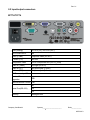
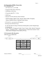
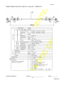
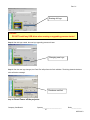
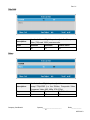
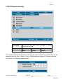
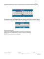
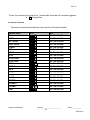
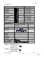
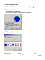
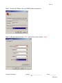
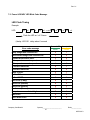
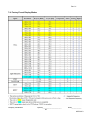
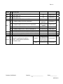
1
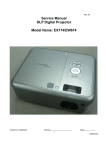
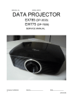
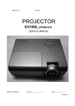
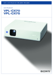
Rev. 01
Service Manual
DLP Digital Projector
Model Name : EP774/TX774
Company Confidential
Optoma_______________________
1
Delta____________
2007/06/13
Rev. 01
Revision
Description
Date
00
Preliminary
06/01/2007
01
Specification(Contrast Ratio & Brightness) revised (Pg5)
Spare parts list revised (Pg70—Pg72)
The views of the IO label revised (Pg9)
06/13/2007
Company Confidential
Optoma_______________________
2
Delta____________
2007/06/13
Rev. 01
CONTENTS
1 . C O M P L I A N C E O F S A F E R E PA I R . . . . . . . . . . . . . . . . . . . . . . . . . . . . . . . . . . . . . . . . . . . . . . . . . . . . . . . . . . .
4
1-1.Cautions During Disassembling And Assembling.........................
4
1-2.Lamp..........................................................................
4
1-3.Lens...................................................................
4
2 . S P E C I F I C AT I O N S . . . . . . . . . . . . . . . . . . . . . . . . . . . . . . . . . . . . . . . . . . . . . . . . . . . . . . . . . . .
5
2-1.Product Specifications......................................................
5
2-2.Input/output
9
connectors..................................................
2-3.Description of Wire Connection............................................10
2-3-1 Accessories List ………………………………………………………………………………10
2 - 3- 2 A c c es s or i es W i r e D es c r ip t i on … … …… …… … …… …… … …… …… … …… …… … 10
2-4.Remote Control keypad......................................................
13
2-5. Control Key Pad and LED..................................................................... 14
2-6.BLOCK
3.TROUBLE
DIAGRAM...........................................................
15
S H O O T I N G. . . . . . . . . . . . . . . . . . . . . . . . . . . . . . . . . . . . . . . . . . . . . . . . . . . . . . . . . . .
16
4 . D I S A S S E M B L Y A N D A S S E M B L Y. . . . . . . . . . . . . . . . . . . . . . . . . . . . . . . . . . . . . . . . . . . . . . . . . . . . . . . . . . . 2 0
5.Firmware................................................................
28
5-1.Projector USB Drivers Installation Guide.................................................28
5 - 2 . D L P P r o j e c t o r F l a s h - To o l ( f i r m w a r e ) U s e r G u i d e . . . . . . . . . . . . . . . . . . . . . . . . . . . . … . 3 7
5 - 3 . D L P P r o j e c t o r F l a s h - To o l ( s p l a s h l o g o ) U s e r G u i d e . . . . . . . . . . . . . . . . . . . . . . . . . . . . . . . . . . . . . . . . 4 2
5-4.How user can reset lamp hours
.................................................48
5-5.Check Lamp hours information in Service mode (J4P Series).....................49
5-6.Overscan rate............................................................................50
5 - 7 . D L P P r o j e c t o r s e c u r i t y. . . . . . . . . . . . . . . . . . . . . . . . . . . . . . . . . . . . . . . . . . . . . . . . . . . . . . . . . . . . . . . . . . . . . . . . . . . . 5 2
5-8.DLP Projector security unlock (Optoma EP774 series)..............................54
6.How To Program By RS232........................................................... 57
7.SERVICE
NOTE...........................................................
65
7-1.Cleaning......................................................................
65
7-2.Remote Control For Battery Replacement.............................. 66
7-3.Power & READY LED Blink Code Message.......................…. 67
7-4.Factory Preset Display Modes................................................. 68
7-5.OPTOMA Splash LOGO screen.........................................................69
7 - 6 . Sp a r e p a r ts l i s t . . . . . . . . . . . . . . . . . . . . . . . . . . . . . . . . . . . . . . . . . . . . . . . . . . . . . . . . . . . . . . . . . . . . . . . . . 7 0
7-7.Carton.................................................................................75
Company Confidential
Optoma_______________________
3
Delta____________
2007/06/13
Rev. 01
1. COMPLIANCE OF SAFE REPAIR
Be sure to read this Service Manual before providing services. In the projector, full consideration is taken
to ensure the safety for a fire, electric shock, injury, harmful radiation, and substance. Therefore, observe the
notice described in this Service Manual so that the safety is kept when providing services. Moreover, be sure to
observe the notice described in the Instruction Manual.
Pay attention to the following during service inspection.
1-1. Cautions during disassembling and assembling
1.This equipment contains parts under high voltage. When making repairs, etc. Be sure to pull out the power
plug beforehand to insure safety.
2. Parts may be very hot immediately after use. Make sure the equipment has cooled off sufficiently before
carrying out repairs.
3. Make sure that parts and screws and wiring, etc. are returned to their original positions. Tube, tape and
other insulation materials have been used for safety reasons. The internal wiring has been designed to
avoid direct contact with hot parts or parts under high voltage when using clamps or other tools.
4. The parts used in this device have special safety features such as flame-resistance and anti-voltage
properties. When replacing parts, always use parts supplied from the factory.
5. After finishing operations make sure that all parts and wires have been returned to their original position
and that there has been no deterioration of the area around the location that was worked on.
6. Be sure to use an earth band (wrist band) during repair and inspection.
1-2. Lamp
During current conduction, the lamp is in the high-temperature state. In this case, pay careful attention because
a high voltage is used. When replacing a lamp, replace it after confirming that the lamp has gotten
cold sufficiently.
1-3. Lens
Do not look through a lens during projection. This damages your eyes.
Company Confidential
Optoma_______________________
4
Delta____________
2007/06/13
Rev. 01
2. SPECIFICATIONS
2-1. Summary Specifications
Design Specification
"TI" DMD, 0.7" x 1, 12∘, XGA
Technology
DDR DLP with DDP2000
Engine System
Delta non-telecentric optical engine J4P
Resolution
Contrast Ratio*
Brightness*
Brightness
Uniformity
Native
XGA 1024x768 Native
Compatibility
Up to SXGA 1280x 1024 @ 75 Hz <140MHz >
Typical
2100:1
Minimum
1900:1
Typical/Minimum (Standard mode)3500/3200 ANSI Lumens
Typical/Minimum (ECO mode)
2800 /2500ANSI Lumens
Typical
80%
Minimum
70%
Test Method
average 4 corners / center at 9 points
Color Reproduction
24 bit, 16.7million True Color
Color Temperature @ normal
6000K
Color Wheel
5-Segment, RYGWB (2x)
R/G/B/W/Y :82/80/78/91/29
44mm
Projection Lens
Manual Zoom and Focus
Digitial Zoom
yes
Zoom Ratio
1.15:1
Projection Distance
1m to 11.2m
Projection Screen Size (diagonal)
23.4"~300"
Projection Method
Front/Rear, Desktop/Ceiling (Rear, Front)
Throw Ratio
Distance/Screen Width
1.8(Wide) - 2.1(Tele)
Effective Focal length
26.01 ~ 29.84mm; 2m @54"
Image Distortion
+/-
Optical Offset
124%
Aspect Ratio
4:3 & 16:9
1 % max
* Note: DELTA will confirm the final figure after 1st MP shipment
Company Confidential
Optoma_______________________
5
Delta____________
2007/06/13
Rev. 01
Keystone Correction
Frequency
+/- 15°(Angle from optical axis)
H-Sync
15, 31~90KHz
V-Sync
50 - 85 Hz
VESA 640x480@60/72/75 Hz
VESA 640x480@ 85Hz
RGB Digital
VESA 800x600@56/60/72/75/85Hz
VESA 1024x768@ 60/70/75/85 Hz
VESA 1280x1024@ 60Hz
VESA 1024x768@85/75/72/70/60 Hz
VESA 800x600@85/75/72/60/56 Hz
RGB Analog
VESA 640x480@85/75/72/60 Hz
VESA 1280x1024@60 Hz
Compatibility
Super VGA, VGA
Macintosh (13", 16" , 19" )
Macintosh
Lamp
Thermal
Power Mac
SDTV
480i,576i (thru RGB HD-15)
EDTV
480p (thru RGB HD-15)
HDTV
576i,720p,1080i (thru RGB HD-15 )
Video
NTSC/NTSC 4.43, PAL( B/G/H/I/M/N 60),
SECAM
Type
Osram E20.6
Standard mode
280W
ECO Mode
230W
Lamp Life for Standard mode
2000 hours
Lamp Life for ECO mode
3000 hours
Survival Rate
50%0
Fan Number
4
Acoustic Noise (normal)
Typical 36dB / max 37dB
Acoustic Noise (ECO)
Typical 33dB / max 34dB
Company Confidential
Optoma_______________________
6
Delta____________
2007/06/13
Rev. 01
Power Supply
Consumption
&
Power Switch
Yes
Voltage(auto-ranging)
Typical @ 110Vac
Standard mode
350W
ECO Mode
230W
Standby
<5W
(watts)
Auto-Ranging Function
Yes
Power Factor Correction
Yes
Material
Plastic
Ceiling Mount
Yes & with tripod mount
Handle
NA
Yes, 1 at front center, 9 degree
Adjustment Leg
(-1~3 degree tilt adjustable at side)
ID Design
Dimensions (WxDxH)
11.81” x 9.61” x 3.95”
(300mm x 244mm x 100.5mm)
Net Weight (Projector Only)
3.7Kg
Gross Weight
6.6Kg(≦14.6 lbs)
Security Lock
Kensington Lock
( ≦8.2 lbs)
Safety & Regulatory Compliance
FCC-B / UL / c-UL / TUV / CB / CE / CCC /
ICES-003 (class B) / eK, CCC, China RoHS
Key Pad Function
Yes
Key Pad Definition
Back Light Design
NA
Power
V
Ez Key/Quick Menu
NA
Auto
V
Source
V
Keystone
V (share with up/down)
Menu
V
Enter
V
Volume (-/+)
V (share with left/right)
Arrow Key +/-/up/down
V
LED Indicator Design
Power
LED Define/Color Lamp Standby
Over Temperature
Company Confidential
Yes
Green
Orange(Amber)
NA
Optoma_______________________
7
Delta____________
2007/06/13
Rev. 01
INPUT Terminals
OUTPUT
Terminals
Data input -I
DVI-I connector accept DVI-D signal
Data input -II
RGB HD-15
Video
Composite Video (RCA x 1)
S-Video
S-Video (Mini DIN)
Component
Yes, thru RGB HD-15
HDMI Digital Video
DVI-D + HDCP
Audio input - I (RCA R& L)
Yes
Audio input -II (Mini Jack)
Yes (mini jack)
Data output
RGB HD-15
Audio Output
Yes (mini jack) -variable adjustment
Control : USB
Control Terminals
Yes (USB-B mouse + keypad emulation +
Flash upgrade )
Control: RS-232
Yes (Room Control)
Screen Control
Yes, 12V
Build-in Speaker
3 w mono speaker (SPL <= 5W)
Plug & Project
EDID1.3, analog RGB & DVI-D (with HDCP)
On-Screen Display (OSD)
1.English
2.French 3.Spanish (Span)
4.German
5.Portuguese
6.Simplefied Chinese 7.Traditional Chinese
8.Italian
9. Norwegian, 10. Swedish
11. Dutch
12. Russian 13. Korean
14. Finnish 15. Greek
16. Danish
17. Polish
Environmental
Temperature
Altitude
Humidity
Non-Operating
-10°C ~ 60°C
Operating
5° ~ 40°C @ sea level
Non-Operating
sea level to 40,000 feet
Operating
sea level to 10,000 feet (@23C)
Non-Operating
5% to 95%
Operating
5% to 90% with maximum wet bulb
temperature of +27°C
Company Confidential
Optoma_______________________
8
Delta____________
2007/06/13
Rev. 01
2-2 Input/output connectors
EP774/TX774
RGB (Analog)
HD-15 x1(I/P), HD-15 x1(O/P),
DVI-D With HDCP
Yes
Video (CVBS)
Composite video (RCAx1)
S-Video (Y/C)
Mini-DIN
Component Video
VGA to Component thru (HD-15_RGB)
Audio in (Video)
Left/Right (RCA x2)
Audio in (PC)
Mini-phone jack (3.5mm)
Audio out(PC)
Mini-phone jack (3.5mm)
DC Power output 12v
Yes
Service/ Firmware
upgrades
USB
Remote Mouse Control USB
Yes
Serial Port(RS-232)
N/A
N/A
Security
Company Confidential
Kensington slot
Optoma_______________________
9
Delta____________
2007/06/13
Rev. 01
2-3. Description Of Wire Connection
2-3-1 Accessories List
1. AC Power Cord x 1 ( US 3.0M)
2. Computer Cable VGA to VGA (2.0m)
3. USB Cable, A to B (2.0m)
4. Composite cable RCA * 1 (1.8m)
5. WEEE card
6. Remote Controller with laser pointer & batteries
7. QTG(10 language: English, French, German, Spanish, Italian, Portuguese,
Russian, Simplified Chinese, Traditional Chinese, Korean
8. CD (Info file , cover artwork as DLP generic)
9.Carrying case with Optoma Logo
10. Lens cap (slide door design, Emboss Eyes Warning label, optoma's designed logo)
11. Warranty card
12.User’s Manual in 18 language ( English, French, German, Italian, Spanish, Portuguese,
Russian, Simplified Chinese, Traditional Chinese, Korean,Dutch, Swedish, Finnish,
Greek, Danish, Norwegian, Polish, Arabic )(CD only)
2-3-2 Accessories Wire Description
USB Cable (2.0m) 3080337300
SHELL
DRAIN
SHELL
4
BLACK
4
3
GREEN
3
2
WHITE
2
1
RED
1
J2
WIRE COLOR
J2
WIRE CONNECTION TABLE
Company Confidential
Optoma_______________________
10
Delta____________
2007/06/13
Rev. 01
CABLE SIGNAL D-SUB D-SUB L2000 BLK (RGB CABLE 2m) P/N:3080425001
Company Confidential
Optoma_______________________
11
Delta____________
2007/06/13
Rev. 01
CABLE SIGNAL RCA RCA L1800 YEL (1.8m) P/N:3080301101
Company Confidential
Optoma_______________________
12
Delta____________
2007/06/13
Rev. 01
2-4. Remote Control Keypad
Remote Control Handset for EP774/TX774
Key
Function
Description
1
Power
Power on/off toggle
2
Laser
Laser pointer trigger, press to emit
laser
3
Up
Up key for emulation of keyboard move
4
Left
Left key for emulation of keyboard move
5
Enter
Enter key for emulation of keyboard move
6
Right
Right key for emulation of keyboard move
7
Down
Down key for emulation of keyboard move
8
Page Up
Page Up key for emulation of keyboard
9
Up arrow
Up key for OSD menu
10 Page Down
Page Down key for emulation of
keyboard
11 Left
Left key for OSD menu
arrow
12 Enter
Enter key for OSD menu
13 Right
arrow Right key for OSD menu
14 Down arrow Down key for OSD menu
15 Keystone +
Keystone correction increment
16 Keystone -
Keystone correction decrement
17 Volume -
Speaker volume decrement
18 Volume +
Speaker volume increment
19 Menu
OSD menu on/off
20 Status
Show status
21 Mute
Speaker mute toggle
22 Auto
Auto adjustment for phase, tracking,
size, position
23 Blank
Display blank & Audio mute
24 Zoom +
Zoom in
25 Source
Input source selection
26 Freeze
Freeze video
27 Zoom -
Zoom out
Company Confidential
Optoma_______________________
13
Delta____________
2007/06/13
Rev. 01
2-5. Control Key Pad and LED
LAMP LED
POWER
Name
Usage
Power LED
Green: Power On
Off :
Power Off
Blink :
Error code
Orange: Lamp is ready to turn on/off
Blink:Lamp not ready (warming up/shutting down & cooling)
Lamp On/Off switch
Source selection
Re-Sync image perfection
Menu On/Off switch
Keystone + when OSD off
Up selection when OSD on,
Keystone – when OSD off
Down selection when OSD on,
Volume + when OSD off
Right selection when OSD on
Volume - when OSD off
Left selection when OSD on
Lamp Ready
LED
Power
Source
Re-sync
Menu
Keystone+ (Up)
Keystone- (Down)
Vol+ (Right)
Vol- (Left)
Company Confidential
Optoma_______________________
14
Delta____________
2007/06/13
Rev. 01
2-6. Block Diagram
OPTOMA EP774/TX774 Structure Diagram
Company Confidential
Optoma_______________________
15
Delta____________
2007/06/13
Rev. 01
3. TROUBLE SHOOTING
J4P serial
By checking operations during normal usage time, it is possible to carry out judgments on malfunction to a certain
Connect the power cord
1. Check cable of Power Supply Unit and thermostat Ass’y.
POWER: Light
NO
2. Check the connection of Power Supply (CON201 of Power board
to CN900 of Main board).
YES
3. Check Power Supply Unit malfunction.
4. Check keypad connection.
POWER、READY:ON
YES
NO
POWER: 4 Blinks
YES
READY: 1 Blink
1.Check Thermal sensor1 Transistor ( Q702 ) malfunction.
2.Check Thermal sensor IC ( U709 ) malfunction.
NO
POWER: 7 Blinks
YES
1. Check Lamp Cover Switch is not attached.
2. Check Lamp Cover connector (CN12) is open.
NO
Waiting Power On
Company Confidential
Optoma_______________________
16
Delta____________
2007/06/13
Rev. 01
Turn the power ON
The lamp is ON
NO
POWER: 4 Blinks
Ready: 1 BLINKS
YES
1.Check Thermal sensor1 Transistor ( Q702 ) malfunction.
2.Check Thermal sensor IC ( U709 ) malfunction.
NO
YES
POWER: 5 Blinks
Ready: 1 BLINKS
Lamp does not light:lighting operation sound (ignition sound) exists.
1. Check Main Board and Ballast Board Ass’y malfunction.
2. Check Ballast to Main board connector (CN530) disconnected.
3. Check Lamp failure (Lamp is broken, damaged, or burst).
NO
READY:1 Blink
1. Check Main board connector (CN800) of Fan disconnected.
2. Check Lamp Fan malfunction.
READY:2 Blink
1. Check Main board connector (CN801) of Fan disconnected.
2. Check Ballast Fan malfunction.
YES
POWER: 6 Blinks
NO
1. Check Main board connector (CN9050) of Fan disconnected.
READY:3 Blink
2. Check Burner fan malfunction.
1. Check Main board connector (CN800) of Fan disconnected.
READY:4 Blink
POWER: 3 Blinks
2. Check Power fan malfunction.
YES
1. Check Thermostat is not attached.
2. Check Main board connector (CN852) is open.
NO
POWER: 9 Blinks
YES
Lamp does not light:No lighting operation sound (ignition sound) exists.
1. Check Flexible cable of Color Wheel Ass’y is disconnected and broken.
NO
2. Color Wheel Ass’y malfunction (does not rotate).
3. Check Main Board Ass’y malfunction (Color Wheel Ass’y does not rotate).
Image
Display
Company Confidential
4. Check Power Supply Unit malfunction.
5. Check Index board malfunction (color wheel turns fast).
Optoma_______________________
17
Delta____________
2007/06/13
Rev. 01
Image
NO
Projector logo screen
YES
1. Check CW Sensor Board Ass’y malfunction.
Confirmation with none-signal state
2. Check Main Board Ass’y malfunction.
YES
1. Check Lamp deterioration (malfunction/usage time).
2. Check Power Supply Unit malfunction.
Still dark after the
(No change occurs even after lamp replacement.)
3. Check DMD Set malfunction.
NO
NO
Menu display
1. Check Remote controller set malfunction, Low battery, and
outside operating rang.
2. Check Main Board Ass’y malfunction.
YES
3. Check Main board connector (CN451) & U451 disconnected.
4. Check IR PWB Ass’y malfunction.
Input each signal
NO
Image display
1. Check the pattern generator setting is wrong.
2. Check Main Board Ass’y malfunction.
3. Check DMD Set malfunction.
4. Check Setting on PC side (external output setting, resolution, etc.)
YES
5. Check Cable malfunction (disconnection and pins broken).
NO
1. Check Wire from IO board ( CN8 ) to Main
board (CN705)
Speaker work
disconnected.
YES
2. Check Speaker Connector to Main board (CN704) disconnected.
Check the
3. Check Speaker Ass’y malfunction.
projection
4. Check Audio PWB Ass’y malfunction.
5. Check Main Board and keypad Board Ass’y malfunction.
Company Confidential
Optoma_______________________
18
Delta____________
2007/06/13
Rev. 01
Check the
Projection
Check using all black/white screens with
PC connection
1. Check Black lines on screen (horizontal and vertical).
→ DMD Set malfunction.
2. Check Missing pixels (Missing white: 1 or more, missing black: 5 or more,
Are abnormalities
YES
or sequence missing pixels).
→ DMD Set malfunction.
noticeable on
3. Check Shadows on screen.
→ Dirt on DMD/projection lens surface.
4. Check Bluish shadows on corners of screen (during white screen display).
→ Shifted optical axis of Lens Base Unit.
NO
YES
1. Check Temperature protector operated due to the increase in
POWER: 3 Blinks
temperature based on operating environment
2. Check Temperature protector operated due to blocked suction and
NO
exhaust holes or dirty fan
System OK
Normal operation
Company Confidential
Optoma_______________________
19
Delta____________
2007/06/13
Rev. 01
4. DISASSEMBLY AND ASSEMBLY
Removing the Lamp Module and Lamp Cover
Look at Top Case side
Loose the two screws.
Open the lamp cover
Loose the two screws and then take out
the lamp module by the ring-pull.
Lamp module views.
Lamp holder views.
Company Confidential
Optoma_______________________
20
Delta____________
2007/06/13
Rev. 01
Removing the Top Cover
Remove the two screws and take off the top case frame
Remove these the eight screws.
Loose the two screws.
Company Confidential
Then remove the top cover.
Optoma_______________________
21
Delta____________
2007/06/13
Rev. 01
Removing the KeyPad / Front Cover / Main Board
Remove these the six screws.
Remove these the six hexagonal bolts.
Remove these the seven screws.
Seven screws.
Open the cover.
Company Confidential
Optoma_______________________
22
Delta____________
2007/06/13
Rev. 01
Removing the Main Board
Fan4 – CN802
Keypad – CN452
Power – CN900
SPK – CN704
Fan2 – CN801
LAMP – CN530
Fan1 – CN800
Fan3 – CN905
Remove tow screws and two nuts
then Disconnect connectors.
CW – CN650
INDEX – CN850
IR2 – CN451
Cover switch – CN812
Company Confidential
Optoma_______________________
23
Delta____________
2007/06/13
Rev. 01
Disassemble the IO Board
Disassemble the main board
Remove the two screws.
Remove the IO Board.
Remove these the five screws.
Check this place when you assemble the
cover.
Remove the IO Case.
Company Confidential
Optoma_______________________
24
Delta____________
2007/06/13
Rev. 01
Disassemble the Ballast and Fan Assy.
Check this place when you assemble the wire. Remove this screw.
Remove this screw.
Remove the Power Supply.
The Power Supply.
Remove these the three screws.
Company Confidential
Optoma_______________________
25
Delta____________
2007/06/13
Rev. 01
Disassemble the Fan and Optic Engine Assy.
Remove the Fan.
The Fan Module and screws.
Remove these the two screws.
Take the heat-sink away.
pull
Remove these the three screws.
Company Confidential
Remove Optic Engine Assy.
Optoma_______________________
26
Delta____________
2007/06/13
Rev. 01
Disassemble the Optic Engine Assy and Power Assy .
View Optic Engine Assy.
View Optic Engine Assy.
pull
pull
Remove Optic Engine Assy.
Remove the two Fan Assy.
Remove these the four screws.
Check this screw when you assemble the wire.
Company Confidential
Optoma_______________________
27
Delta____________
2007/06/13
Rev. 01
5. Firmware
5-1 Projector USB Drivers Installation Guide
Ver 5.0
NOTE:
The user must have administrative privileges on the target computer in order to
install your driver. The installation target directory must not write protected.
Attention: This utility is for DDP2000/2030 series projector only.
System Requirement
IBM compatible PC.
Windows XP-SP2
Operator may need
basic knowledge of Windows device installation.
Install Flash-Tool to PC
Run the “Digital Zoom Projector Flash Tool Vx.y.msi”, it will automatically launch the USB drivers update. Following
are the dialogues of the Driver Install process…
This is the first page of install dialog.
This is the driver installation destination dialogue, use “Change” button
to override the default directory if you decide to put it into different
place.
Ready to install the drivers into the PC, press <Install> to start.
Company Confidential
Optoma_______________________
28
Delta____________
2007/06/13
Rev. 01
The Installer copies the necessary files to PC.
Press the <Finish> button with the Launch checkbox checked, the
wizard will start the INF update.
Launch the
driver update
Note:
The INF update may take a while depends your computer speed and INF numbers…,
Be patient! These windows will automatically close after the updating finished.
Company Confidential
Optoma_______________________
29
Delta____________
2007/06/13
Rev. 01
The install program copy the new INF into Windows
directory, it will search the old INF and replace it with the
newer one.
Remove the USB cable between PC and projector if it is
connected.
The WinDrive USB drivers will be installed and
registered to system.
After the driver install, a test application will start
automatically with Windows hardware wizard for all
necessary USB driver.
The driver test launched, wait for the key stroke to enter Projector
Control mode…
Connect the USB cable now!
If the driver test application does not launch automatically, run the
“Launch FlashToolBL.exe” from installed short cut at
Program> Digital Zoom Projector> projector flashtool version 5> Launch FlasToolBL.exe
Company Confidential
Optoma_______________________
30
Delta____________
2007/06/13
Rev. 01
Make sure the USB cable is firmly attached between projector
and computer; the power switch is in ON position and projector
is in STAND BY mode.
Press <Down>, <Up>, <Right>, <Up> key in sequence on
keypad (DP16/DP18/DP3622 series) or IR remote controller (DP02
series)。 The power and lamp LED will blink and the Projector Control
mode will be enabled.
The New Hardware Wizard launched at the first time Windows
detects a new USB device attached. Use the recommended
suggestion usually works all the way in the process. (Select “No, not
this time”; Press the Next) (Windows XP-SP2)
(Press the Next)
Windows detected and updating the USB Projector Control driver.
Company Confidential
Optoma_______________________
31
Delta____________
2007/06/13
Rev. 01
Windows completed the new hardware wizard.
Press Finish to end the Wizard.
Note:
In case you got USB enumeration problem, the USB no longer recognize your projector!
Please clear the USB items in the windows registry and install the Flashtool USB driver again.
(Ref: Appendix-A)
Once the Projector Control USB driver enumerated; the projector
information displays in the status pane. Press the <Check> button
will drive the projector turns into Flashtool mode. This is verifying that
if the projector will switch to Flashtool mode or not!
The projector is switching to Flashtool mode after click the <Check>…
Company Confidential
Optoma_______________________
32
Delta____________
2007/06/13
Rev. 01
The Windows New Hardware Wizard will launch again for the second USB Projector Control.
(Select “No, not this time”; Press the Next) ( Windows XP-SP2)
Follow the recommended options and process the driver installation.
(Press the Next)
Wizard copies the necessary files and updates the driver.
Windows New Hardware Wizard launches for the Projector Flashtool
USB device.
(Select “No, not this time”; Press the Next) (Windows XP-SP2)
Company Confidential
Optoma_______________________
33
Delta____________
2007/06/13
Rev. 01
Follow the recommended options and process the driver installation.
(Press the Next)
Wizard copies the necessary files and updates the driver.
Flashtool USB driver installed.
Press Finish to end the Wizard.
Congratulations! Power off the projector now, your driver has been
checked and works for Flashtool.
Company Confidential
Optoma_______________________
34
Delta____________
2007/06/13
Rev. 01
Appendix-A
How to clear the USB enumeration registry?
Run “regedit” and select the following items
HKEY_LOCAL_MACHINE->SYSTEM->CurrentControlSet->Enum->USB->
The DP3635 series
VID_1501&Pid_3635xxx
Press <Delete> and remove these registries. (You need the read/write privilege of the Windows registry to delete it.
Select the item and click right mouse will lead you to the Permissions dialog for applying the security options)
Company Confidential
Optoma_______________________
35
Delta____________
2007/06/13
Rev. 01
Appendix-B
Projector USB status on Windows Device Manager
The USB HID device will be installed automatically via Windows' USB hot-plug mechanism.
The Projector Control will be dynamically installed
after
entering the maintenance mode
(Hit key sequence as <down>, <up>, <right>, <up>);
The
Projector Flashtool will be dynamically installed
when starting the flash upgrading by Flashtool or FlashtoolBL utility.
The WIndriver is the root driver for both Projector Control and Flashtool.
Company Confidential
Optoma_______________________
36
Delta____________
2007/06/13
Rev. 01
5-2 DLP Projector Flash-Tool (firmware) User Guide
Ver 5.0
NOTE:
The user must have administrative privileges on the target computer in order to
install your driver. The installation target directory must not write protected.
Attention: This utility is for DLP DDP2000/3020 series projector only.
System Requirement:
. IBM compatible PC.
. Windows XP operating system (English).
. Operator must have basic knowledge of Windows device installation.
. Projector Flashtool USB driver installed.
Install Flash-Tool to PC
Run the “Digital Zoom Projector Flash Tool Vx.y.msi”, if your projector USB drivers not installed yet! Check the USB
driver installation guide about the how-to.
Company Confidential
Optoma_______________________
37
Delta____________
2007/06/13
Rev. 01
Flash-Tool User’s Guide (upgrading projector firmware)
Step 1: Launch the “FlashTool.exe” from installed short-cut at
Program > Digital Zoom Projector> Launch FlasTool.exe or click the “Lauch FlashTool.exe” shortcut icon on the
desktop.
Step 2: Following is the screen capture when there is no projector connected.
Company Confidential
Optoma_______________________
38
Delta____________
2007/06/13
Rev. 01
Step 3: Make sure the USB cable is firmly attached between projector and computer; the power switch is in
ON position (if the projector got hardware power switch) and projector is in STAND BY mode.
Press <Down>, <Up>, <Right>, <Up> key in sequence on keypad (DP2601/2618/3618 series) or IR remote
controller (DP3602 series)。 The power and lamp LED will blink and the Flash-Tool mode will be enabled.
Press “Choose” to select file
Projector information
Note:
The Windows hardware wizard will pop up if the USB device driver is not installed. Just select
. the recommended options and let Windows Wizard do it automatically…
Step 4: Press “Choose” button to locate the new firmware which can be downloaded from website (for example:
DP3635-JAXX-DPD0A.img). Select the candidate .img file and either double click it or press the “Open” button to
load the file.
Use img file type for
firmware binary data
Company Confidential
Optoma_______________________
39
Delta____________
2007/06/13
Rev. 01
Step 4-1:.The Flashtool will validate the signature of the binary image file for upgrading. The “Start” button will not
enable if the binary image is not a valid projector firmware.
The “Start” button
Step 5: Press “Start” button to start flash the firmware into projector, the warning message box will appear to get
your confirmation. Press <OK> to continue.
Step 6: The last warning message box appears, this is the last chance to stop the update, press “OK” button to start
the firmware update.
Company Confidential
Optoma_______________________
40
Delta____________
2007/06/13
Rev. 01
Caution:
DO NOT install any USB driver when erasing or upgrading process started.
Step 7: By the Flash technology, the old firmware needs to be erased first. Flash-Tool will automatically erase the
old firmware before upgrading.
Erasing status
Caution:
DO NOT install any USB driver when erasing or upgrading process started.
Step 8: After old firmware erased, the new firmware upgrading process will start.
Upgrading new firmware
Company Confidential
Optoma_______________________
41
Delta____________
2007/06/13
Rev. 01
Step 9: After the new firmware upgraded, the Flash-Tool will perform the final validation. The dialog showed
checksum with verification message!
Checksum verified
Step 10: Done! Power off the projector.
5-3 DLP Projector Flash-Tool (splash logo) User Guide
NOTE:
The user must have administrative privileges on the target computer in order to
install your driver. The installation target directory must not write protected.
Attention: This utility is for DLP DDP2000/3020 series projector only.
Ver 5.0
System Requirement:
. IBM compatible PC.
. Windows XP operating system (English).
. Operator must have basic knowledge of Windows device installation.
. Projector Flashtool USB driver installed.
Install Flash-Tool to PC
Run the “Digital Zoom Projector Flash Tool Vx.y.msi”, if your projector USB drivers are not installed yet! Check the
USB driver installation guide about the how-to.
Company Confidential
Optoma_______________________
42
Delta____________
2007/06/13
Rev. 01
Flash-Tool User’s Guide (upgrading projector logo)
Step 1: Launch the “FlashTool.exe” from installed short-cut at
Program > Digital Zoom Projector> Launch FlasTool.exe or click the “Lauch FlashTool.exe” shortcut icon on the
desktop.
Step 2: Following is the screen capture when there is no projector connected.
Company Confidential
Optoma_______________________
43
Delta____________
2007/06/13
Rev. 01
Step 3: Make sure the USB cable is firmly attached between projector and computer; the power switch is in
ON position (if the projector got hardware power switch) and projector is in STAND BY mode.
Press <Down>, <Up>, <Right>, <Up> key in sequence on keypad (DP2601/2618/3618 series) or IR remote
controller (DP3602 series)。 The power and lamp LED will blink and the Flash-Tool mode will be enabled.
Press “Choose” to select file
Projector information
Note:
The Windows hardware wizard will pop up if the USB device driver is not installed. Just select
. the recommended options and let Windows Wizard do it automatically…
Company Confidential
Optoma_______________________
44
Delta____________
2007/06/13
Rev. 01
Step 4: Press “Choose” button and select either BMP or JPG in the “File of type” option.
BMP/JPG selection
Step 4-1: Double click the logo file or use open button to select the logo you want.
Step 4-2:.The Flashtool will validate the size of the logo file. Logo will be converted to RLE format and stored to the
projector’s flash memory. The compressed RLE size can not exceed the flash memory limitation. In case of the size
problem, try to reduce the colors by select the JPEG colors option in the tool. (Valid only for JPEG files)
JPEG color selection
Company Confidential
Optoma_______________________
45
Delta____________
2007/06/13
Rev. 01
Step 5: Press “Start” button to start flash the firmware into projector, the warning message box will appear to get
your confirmation. Press <OK> to continue.
Step 6: The last warning message box appears, this is the last chance to cancel the update, press “OK” button to
start the logo change.
Caution:
DO NOT install any USB driver when erasing or upgrading process started.
Step 7: By the Flash-ROM technology, Flash-Tool need to erase the old logo data before it can change it.
Company Confidential
Optoma_______________________
46
Delta____________
2007/06/13
Rev. 01
Erasing old logo
Caution:
DO NOT install any USB driver when erasing or upgrading process started
Step 8: After old logo erased, the new logo upgrading process will start.
Changing new logo
Step 9: After the new logo changed, the Flash-Tool will perform the final validation. The dialog showed checksum
with verification message!
Checksum verified
Step 10: Done! Power off the projector.
Company Confidential
Optoma_______________________
47
Delta____________
2007/06/13
Rev. 01
5-4 How user can reset lamp hours !!
After replacing the lamp, you should reset the lamp hour counter to zero. Refer to the following:
1.
Press the Menu button to open the
Main menu.
2.
Press the cursor
button to move
to the Status menu.
3.
Press the cursor
button to move
down to Lamp Hour Reset.
4.
Press the cursor
or Enter button.
A message screen appears.
5.
Press the cursor buttons in this order:
;
;
;
.
The Status menu appears again
showing the Lamp Hours reset to
zero.
Company Confidential
Optoma_______________________
48
Delta____________
2007/06/13
Rev. 01
5-5 Check Lamp hours information in Service mode (J4P Series)
In Status Menu , select Lamp Hour Reset
Step1
function,and press “Enter” key on keypad or IR
controller to go into Lamp Hours Reset
sub-page。.
Step2
In Lamp Hours Reset sub-page press “Enter”,
“Enter”, “Up” , “Down” , “Left”, “Right” in
sequence。
After press password right , it will go into a
Service page。Used up / down key on keypad
Step3
or IR to highlight the item “Lamp Hours
Information” and press “Select/Right” to go
into Lamp Hours Information menu.
In Lamp Hours Information menu, “Normal
Mode Lamp Hours “ show normal mode lamp
hours usage in current lamp.
“Eco Mode Lamp Hours “ show eco mode
lamp hours usage in current lamp.
Step4
“Boost Mode Lamp Hours “ show boost mode
lamp hours usage in current lamp.
“Current Lamp Hours “ show current lamp
hours usage in current lamp(Normal + Eco +
Boost).
“Total Lamp Hours “ show all lamp hours
usage in projector (cann’t be reset).
Company Confidential
Optoma_______________________
49
Delta____________
2007/06/13
Rev. 01
5-6 Overscan Rate
Description:
Enter the overscan rate menu.
Overscan Rate Menu
Company Confidential
Optoma_______________________
50
Delta____________
2007/06/13
Rev. 01
720p/1080i
Description:
Use the Left and Right keys to adjust the Component
Video (720p and 1080i) overscan ratio.
Steps
Minimum
Maximum
Default value
2
On
Off
Off
Description:
Use the Left and Right keys to adjust those overscan ratio
except 720p/1080i (i.e. the SVideo, Composite Video,
Component Video 480i, 480p, 576i, 576p).
Steps
Minimum
Maximum
Default value
2
On
Off
ON
Others
Company Confidential
Optoma_______________________
51
Delta____________
2007/06/13
Rev. 01
5-7 DLP Projector security
Description:
Use the Left and Right keys to enable or disable
security lock function.
Steps
Minimum
Maximum
Default value
2
Enable
Disable
Disable
The Password Menu will be displayed if the “Security Lock” enabled. The available keys for the
password entry are <Up>, <Down>, <Left>, <Right> either on keypad or IR remote controller.
Use <Menu> to cancel the password input.
Company Confidential
Optoma_______________________
52
Delta____________
2007/06/13
Rev. 01
If Register Password is the same as Confirm Password, the password will be memorized.
The password confirm menu appears when user press the power-on key in case the “Security
Lock” function enabled. Only <Up>, <Down>, <Left>, <Right> and <Power> key are available.
How to reset password:
In case of lost of the password, please contact with the service-center.
Service-center will validate the owner and help resetting the password.
(See “DLP Projector security unlock guide”)
.
Company Confidential
Optoma_______________________
53
Delta____________
2007/06/13
Rev. 01
5-8 DLP Projector security unlock (Optoma EP774 series)
Ver 1.0.2
The document is to describe a Windows application software “DLPunlock” for projector password unlock. Its main
purpose is to provide a way to reset the forgotten password, the application will ship to the call-center and help the
validated end-user to reset the password.
Hint code Input at
here.
User can get the
hint code from
projector OSD.
Press here to
generate the
key
Key for resetting
the password
Company Confidential
Optoma_______________________
54
Delta____________
2007/06/13
Rev. 01
J4P security password reset flow-chart
Company Confidential
Optoma_______________________
55
Delta____________
2007/06/13
Rev. 01
Projector OSD for password check & reset
Password validates
at power-on.
Password input at
power-on.
Hint code appeared
when wrong password
input over 5 times.
Company Confidential
Optoma_______________________
56
Delta____________
2007/06/13
Rev. 01
6. How To Program By RS232
Projection Display Serial Interface
6-1 RS232 Setting
Baud rate:
9600
Parity check:
None
Data bit:
8
Stop bit:
1
Flow Control
None
Minimum delay for next command: 1ms
6-2 Control Command Structure
The command is structured by the Header code, command code, data code and end code.
Most of the commands are structured except some for the compatibility issue with other
projectors.
Header code
Command code Data code End code
HEX
7Eh
Command
Data
0Dh
ASCII
‘~’
Command
Data
CR
6-3 Control Sequence
The projector may send a return code after it received a command. If the command isn’t
received correctly, the projector will not send the return code
6-4 Operation Command
The operation commands execute the basic operation setting of this projector.
Operation
Power On
ASCII
~ P N CR ※
HEX
Power Off
~ P F CR
7Eh 50h 46h 0Dh
Auto Image
~ A I CR
7Eh 41h 49h 0Dh
Input Select RGB
~ S R CR
7Eh 53h 52h 0Dh
Input Select RGB2
~ S G CR
7Eh 53h 47h 0Dh
Input Select DVI
~ S D CR
7Eh 53h 44h 0Dh
Input Select Video
~ S V CR
7Eh 53h 56h 0Dh
Input Select S-Video
~ S S CR
7Eh 53h 53h 0Dh
Input Select Component
~ S Y CR
7Eh 53h 59h 0Dh
Input Select Wireless
~ S W CR
7Eh 53h 57h 0Dh
Company Confidential
※
7Eh 50h 4Eh 0Dh
Optoma_______________________
57
Delta____________
2007/06/13
Rev. 01
* Power On command will not work for 1 minute after the power off command triggered.
CR : Carriage Return.
6-5 Remote Command
The remote commands simulate the code send from IR remote handset.
Button’s name
ASCII
HEX
UP arrow
~ r U CR
7Eh 72h 55h 0Dh
DOWN arrow
~ r D CR
7Eh 72h 44h 0Dh
LEFT arrow
~ r L CR
7Eh 72h 4Ch 0Dh
RIGHT arrow
~ r R CR
7Eh 72h 52h 0Dh
POWER
~ r P CR
7Eh 72h 50h 0Dh
EXIT
~ r E CR
7Eh 72h 45h 0Dh
INPUT
~ r I CR
7Eh 72h 49h 0Dh
AUTO
~ r A CR
7Eh 72h 41h 0Dh
KEYSTONE+
~ r K CR
7Eh 72h 4Bh 0Dh
KEYSTONE-
~ r J CR
7Eh 72h 4Ah 0Dh
MENU
~ r M CR
7Eh 72h 4Dh 0Dh
STATUS
~ r S CR
7Eh 72h 53h 0Dh
MUTE
~ r T CR
7Eh 72h 54h 0Dh
ZOOM+
~ r Z CR
7Eh 72h 5Ah 0Dh
ZOOM-
~ r Y CR
7Eh 72h 59h 0Dh
BLANK
~ r B CR
7Eh 72h 42h 0Dh
FREEZE
~ r F CR
7Eh 72h 46h 0Dh
VOLUME+
~ r V CR
7Eh 72h 56h 0Dh
VOLUME-
~ r W CR
7Eh 72h 57h 0Dh
Enter
~ r N CR
7Eh 72h 4Eh 0Dh
Company Confidential
Optoma_______________________
58
Delta____________
2007/06/13
Rev. 01
6-6. Set Value Command
ITEM
ASCII
HEX
Brightness
~ s B ? CR ※
7Eh 73h 42h ?h 0Dh
Contrast
~ s C ? CR
7Eh 73h 43h ?h 0Dh
Color
~ s R ? CR
7Eh 73h 52h ?h 0Dh
Tint
~ s N ? CR
7Eh 73h 4Eh ?h 0Dh
Scaling
~ s A ? CR
7Eh 73h 41h ?h 0Dh
Color Temperature
~ s T ? CR
7Eh 73h 54h ?h 0Dh
Projection Mode
~ s J ? CR
7Eh 73h 4Ah ?h 0Dh
? : ASCII Data
Data Range
ITEM
Set Data Range
Source
Brightness
0 ~ 100
ALL
Contrast
0 ~ 100
ALL
Color
0 ~ 100
Video/S-Video/Component
Tint
0 ~ 100
Video/S-Video/Component
Scaling
0: 4:3 1: 16:9
ALL
Color Temperature
0:Cool 1:Ceiling 2:Warm
ALL
Projection Mode
0:Front 1:Rear 2:Rear+Ceiling
3: Ceiling
ALL
Attention: Data range may be different for different models
Example 1.
Adjust Brightness value to 100
Send Command : ~sB100CR
Example 2.
Adjust Color Temperature to Warm
Send Command : ~sT2CR
Company Confidential
Optoma_______________________
59
Delta____________
2007/06/13
Rev. 01
6-7. Query Command
ITEM
ASCII
HEX
Software Version
~ q V CR
7Eh 71h 56h 0Dh
Power State
~ q P CR
7Eh 71h 50h 0Dh
Input Select
~ q S CR
7Eh 71h 53h 0Dh
Lamp Hours
~ q L CR
7Eh 71h 4Ch 0Dh
Brightness
~ q B CR
7Eh 71h 42h 0Dh
Contrast
~ q C CR
7Eh 71h 43h 0Dh
Color (Video)
~ q R CR
7Eh 71h 52h 0Dh
Tint (Video)
~ q N CR
7Eh 71h 4Eh 0Dh
Scaling
~ q A CR
7Eh 71h 41h 0Dh
Color Temperature
~ q T CR
7Eh 71h 54h 0Dh
Projection Mode
~ q J CR
7Eh 71h 4Ah 0Dh
Response message
ITEM
Response Message
examples
Software Version
…..
Power State
On Off
Input Select
RGB DVI Video S-Video
Component DVD HDTV
Lamp Hours
2000
Brightness
100
Contrast
100
Color (Video)
100
Tint (Video)
100
Scaling
4:3 16:9
Color Temperature
Cool Normal
Projection Mode
Front Rear+Ceiling Rear Ceiling
Example 1.
Example 2.
Get Brightness value
Send Command : ~qBCR
Response : 100
Get Color Temperature
Send Command : ~qTCR
Response : Warm
Company Confidential
Optoma_______________________
60
Delta____________
2007/06/13
Rev. 01
6-8. Hyper Terminal setting guide
6-8-1 Connect the RS232 Cable between your computer and Projector。
6-8-2 Open HyperTerminal
Window2000/XP HyperTerminal path:
Start \ Programs \ Accessories \ Communications \ HyperTerminal。
6-8-3 Setting the HyperTerminal parameter:
Step 1. Type the connection name .
Company Confidential
Optoma_______________________
61
Delta____________
2007/06/13
Rev. 01
Step2 . Choose the COM port for your RS232 Cable connected to.
Step3. In Bits per second choose “ 9600 ” and in Flow control choose “ None ”。
Company Confidential
Optoma_______________________
62
Delta____________
2007/06/13
Rev. 01
Step4. Click the File and choose Properties to setting Keyboard parameter。
Step5. In Setting page , choose Emulation type for your keyboard.
Step6. Click ASCII Setting icon to setup ASCII code parameter.
Company Confidential
Optoma_______________________
63
Delta____________
2007/06/13
Rev. 01
Step7. Mark Send Line ends with line feeds and Echo typed characters locally and click OK bottom to
complete setting.
Company Confidential
Optoma_______________________
64
Delta____________
2007/06/13
Rev. 01
7. SERVICE NOTE
7-1. Cleaning
Carry out cleaning of the main unit and interior when replacing
the lamp or making inspections.
The glass cleaner used with the following parts is as follows.
Product name : Kei-Dry Wiper 132-S (Kureshia Co., Ltd.)
1)Cleaning the Projection Lens
*When dust and fingerprints, etc. are on the lens surface, use
the designated glass cleaner to remove as shown in the figure
at the right. For fingerprints and other soiling that are difficult
to remove with a dry cloth, use a designated glass cleaner
which has been moistened in water and then use a dry cloth
to dry it off.
*The projection lens surface has a special coating. Do not use
detergents or solvents on the surface.
2) Cleaning the Color Wheel Assy.
*The color filter is made of thin glass. Be very careful when
handing the filter.
*In case of fingerprints, etc. on the surface, clean in the same
way as the projection lens unit as described in item 1). Do not
use detergents as this could cause peeling of the color filter.
3) Cleaning the DMD
*The DMD surface is glass and can be cleaned. However, avoid
scratches as these can have a direct influence on the image.
*In case of dust on the DMD surface use an air cleaner ( with a
device to prevent static, if possible) to clean off the surface.
*In case of fingerprints, etc., add a small amount of water to the
designated glass cleaner and wipe off in one direction. Then
use the designated dry glass cleaner to wipe off in the same
direction.
*Do not use absolute alcohol or other substances that could
leave streaks after drying.
4) Cleaning the Reflecting Mirror
*Be careful not to touch the reflecting mirror. The surface is
composed of vapor deposition silver and touching it directly
with the hands can lead to burnishing.
*Do not clean other than with air.
5) Cleaning the Main Unit
*Clean with a soft fuzz-free cloth. In case of severe soiling, use
a well-wrung cloth dipped in a neutral agent to remove soiling
and then finish with a dry cloth.
*Do not clean with thinner, benzene or similar agents as this
could lead to deterioration or peeling of paint.
*In case of dust in suction or exhaust holes or the interior,
disassemble the main unit and use air to remove the dust from
the inside.
Company Confidential
Optoma_______________________
65
Delta____________
2007/06/13
Rev. 01
7-2. Remote control for battery replacement
Company Confidential
Optoma_______________________
66
Delta____________
2007/06/13
Rev. 01
7-3. Power & READY LED Blink Code Message
LED Flash Timing
Example:
LED
on
off
on
off
on
off…※delay on off
on off
on
off
Flash the LED on / off 3 times
※delay: LED Off
delay about 1 second
Power LED
Blink
Ready LED
Blink
Lamp usage task created error
2
1
Environment usage task created error
2
2
Thermal break status error
3
0
T1 temperature over temperature
3
1
T2 temperature over temperature
3
2
T1 sensor status fail
4
1
T2 sensor status fail
4
2
Lamp lit error
5
1
Ballast SCI error
5
2
Ballast UART error
5
3
Fan1 error (Lamp)
6
1
Fan2 error (Ballast)
6
2
Fan3 error (Burner)
6
3
Fan4 error (Power)
6
4
Lamp door sensor detect high
7
0
DMD error
8
0
Color wheel error
9
0
Error code message
Company Confidential
Optoma_______________________
67
Delta____________
2007/06/13
Rev. 01
7-4. Factory Preset Display Modes
Company Confidential
Optoma_______________________
68
Delta____________
2007/06/13
Rev. 01
7-5. OPTOMA Splash LOGO screen
Company Confidential
Optoma_______________________
69
Delta____________
2007/06/13
Rev. 01
7-6.Spare parts list
1. EP774 (WHITE:DP-3635 NOTDC/NOTEG/NOTZG/NOTDG/NOTIG/NOTFG/NOTDI)
(GRAY: DP-3635 NOTCG)
EP774 Spare part list
TYPE NO
Cover
1
DESCRIPTION
Model
WHITE
CASE TOP ASSY DP-3622
(TOP CASE)
GRAY
Cover
2
CASE BOTTOM ASSY DP-3622
(BOTTOM CASE)
WHITE
GRAY
Cover
3
WHITE
CASE BACK ASSY DP-3622
(BACK CASE)
GRAY
Cover
4
WHITE
LAMP COVER PC 94V0
(LAMP COVER)
GRAY
Foot
5
Fan
Fan
Fan
Fan
Board
Board
Board
Ballast
Optical
Lamp
module
Carton
6
7
8
9
10
11
12
13
14
ADJ FRONT FOOT LEG PC 94V0
(HEIGHT ADJUSTER)
WHITE
GRAY
DC FAN ASSY BUB0612HB-SM00 L160/120 60 B
DC FAN ASSY NUB0612MB-R00 L35/5 60 B
DC FAN ASSY AFB0712HB-SE32 L115/75 70 B
DC FAN ASSY AFB0712HB-F00 L55/15 70 B
DMD BD ASSEMBLY
POWER BOARD ASSEMBLY
MAIN BOARD ASSEMBLY
LAMP DRIVER 280W PULSE
MODULE 0.7" XGA OPTICAL 280W ASSY
15 LAMP MODULE J4P E20.6 280W ASSY DP-3635
16 CARTON PAPER 434*378*258
SPEAKER ASSEMBLY
Speaker 17
(80hm 3W 290mm Wire, 51mm*40.6mm*25mm)
KEYPAD BOARD ASSEMBLY
Keypad 18
(112mm x 65mm x 1.2mm FR-4 )
Company Confidential
DP-3635 NOTDC
/NOTEG/NOTZG
/NOTDG/NOTIG
/NOTFG/NOTDI
DP-3635 NOTCG
DP-3635 NOTDC
/NOTEG/NOTZG
/NOTDG/NOTIG
/NOTFG/NOTDI
DP-3635 NOTCG
DP-3635 NOTDC
/NOTEG/NOTZG
/NOTDG/NOTIG
/NOTFG/NOTDI
DP-3635 NOTCG
DP-3635 NOTDC
/NOTEG/NOTZG
/NOTDG/NOTIG
/NOTFG/NOTDI
DP-3635 NOTCG
DP-3635 NOTDC
/NOTEG/NOTZG
/NOTDG/NOTIG
/NOTFG/NOTDI
DP-3635 NOTCG
ALL
ALL
ALL
ALL
ALL
ALL
ALL
ALL
ALL
P/N
Q'ty
3398032806
1
3398033105
3398032602
1
3398033201
3398031600
1
3398033000
3392027502
1
3392040301
3392023202
1
3392040201
3620629911
3620631711
3620711111
3620711211
5600204372
5600600519
5600600459
0990076600
5811100174
1
1
1
1
1
1
1
1
1
ALL
5811100173
1
ALL
3517129702
1
ALL
3791001806
1
ALL
5600600271
1
Optoma_______________________
70
Delta____________
2007/06/13
Rev. 01
TYPE NO Accessories
Cable
Cable
Cable
Q'ty
CABLE SIGNAL USB USB L2000 IVORY
(USB CABLE 2m)
CABLE SIGNAL D-SUB D-SUB L2000 BLK
20
(RGB CABLE 2m)
21 CABLE SIGNAL RCA RCA L1800 YEL
19
ALL
3080337300
1
ALL
3080425001
1
3080301101
1
28 AC POWER CORD 3P 3G*1.0mm^2 L3000 BLK UK
ALL
DP-3635 NOTZG
/NOTCG
DP-3635
NOTDC/NOTDG
/ NOTDI
DP-3635 NOTEG
29 AC POWER CORD 3P 3G* 1.0mm^2 L3000 BLK C
DP-3635 NOTFG
3090123801
30 AC POWER CORD 3P 3G*1.0mm^2 L3000 BLK AU
DP-3635 NOTIG
3090211300
ALL
3534017304
1
ALL
ALL
DP-3635 NOTDC
/NOTEG/NOTZG
/NOTDG/NOTIG
/NOTFG/NOTDI
5010054300
3523018900
1
1
26 AC POWER CORD 3P #18*3C L3000 BLK
Cable
CD
Manual
Case
Remote
27 AC POWER CORD 3P 3G*0.75mm^2 L3000 BLK E
22 CD SOFTWARE PACKING ASSEMBLY (CD Disc)
23 MANUAL QUICK START GUIDE TROUBLE SHOOTING
24 CARRYING CASE PP 330*290*110
REMOTE CONTROLLER 27KEYS
25 (27KEY LASER MEDIA IR REMOTE
CONTROL UNIT)
WHITE
GRAY
Company Confidential
DP-3635 NOTCG
Optoma_______________________
71
3072050701
3090211202
1
3090211102
5041814200
1
5041814400
Delta____________
2007/06/13
Rev. 01
2. TX774
(DP-3635 NOTCH/ NOTCI)
TX774 Spare part list
TYPE NO
DESCRIPTION
Model
P/N
Q'ty
CASE TOP ASSY DP-3622 DUMMY (TOP CASE)
CASE BOTTOM ASSY DP-3622 DUMMY
(BOTTOM CASE)
ALL
3398033105
1
ALL
3398033201
1
Cover
1
Cover
2
Cover
3
CASE BACK ASSY PD-3622 DUMMY (BACK CASE)
ALL
3398033000
1
Cover
4
LAMP COVER PC+ABS 94V0 GRAY (LAMP COVER)
ALL
3392040301
1
Foot
5
ADJ FRONT FOOT LEG PC 94V0 GRAY
(HEIGHT ADJUSTER)
ALL
3392040201
1
Fan
6
DC FAN ASSY BUB0612HB-SM00 L160/120 60 B
ALL
3620629911
1
Fan
7
DC FAN ASSY NUB0612MB-R00 L35/5 60 B
ALL
3620631711
1
Fan
8
DC FAN ASSY AFB0712HB-SE32 L115/75 70 B
ALL
3620711111
1
Fan
9
DC FAN ASSY AFB0712HB-F00 L55/15 70 B
ALL
3620711211
1
Board
10 DMD BD ASSEMBLY
ALL
5600204372
1
Board
11 POWER BOARD ASSEMBLY
ALL
5600600519
1
Board
12 MAIN BOARD ASSEMBLY
ALL
5600600459
1
Ballast
13 LAMP DRIVER 280W PULSE
ALL
0990076600
1
Optical
14 MODULE 0.7" XGA OPTICAL 280W ASSY
ALL
5811100174
1
Lamp
module
15 LAMP MODULE J4P E20.6 280W ASSY
ALL
5811100173
1
Carton
16 CARTON PAPER 434*378*258
ALL
3517129702
1
Speaker 17
ALL
3791001806
1
Keypad
ALL
5600600271
1
SPEAKER ASSEMBLY
(80hm 3W 290mm Wire, 51mm*40.6mm*25mm)
KEYPAD BOARD ASSEMBLY
18
(112mm x 65mm x 1.2mm FR-4 )
TYPE NO Accessories
Cable
Cable
CABLE SIGNAL USB USB L2000 IVORY
(USB CABLE 2m)
CABLE SIGNAL D-SUB D-SUB L2000 BLK
20
(RGB CABLE 2m)
19
Q'ty
ALL
3080337300
1
ALL
3080425001
1
Cable
21 CABLE SIGNAL RCA RCA L1800 YEL
ALL
3080301101
1
Cable
26 AC POWER CORD 3P #18*3C L3000 BLK
ALL
3072050701
1
CD
22 CD SOFTWARE PACKING ASSEMBLY (CD Disc)
ALL
3534017304
1
Manual
23 MANUAL QUICK START GUIDE TROUBLE SHOOTING
ALL
5010054300
1
Case
24 CARRYING CASE PP 330*290*110
ALL
3523018900
1
5041814400
1
REMOTE CONTROLLER 27KEYS DP-3622 JOTCH
ALL
Remote 25
(27KEY LASER MEDIA IR REMOTE CONTROL UNIT)
Company Confidential
Optoma_______________________
72
Delta____________
2007/06/13
Rev. 01
28
26
27
29
Company Confidential
30
Optoma_______________________
73
Delta____________
2007/06/13
Rev. 01
Company Confidential
Optoma_______________________
74
Delta____________
2007/06/13
Rev. 01
7-7. Carton
Company Confidential
Optoma_______________________
75
Delta____________
2007/06/13