1
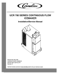
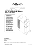
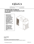
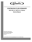
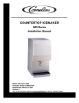
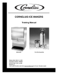
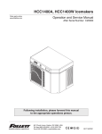
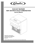
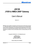
CONTINUOUS FLOW ICEMAKER WCC 2001 QT - R Service Manual Release Date: September 21, 2005 Publication Number: 630460308SER Revision Date: March 18, 2014 Revision: G Visit the Cornelius web site at www.cornelius.com for all your Literature needs. The products, technical information, and instructions contained in this manual are subject to change without notice. These instructions are not intended to cover all details or variations of the equipment, nor to provide for every possible contingency in the installation, operation or maintenance of this equipment. This manual assumes that the person(s) working on the equipment have been trained and are skilled in working with electrical, plumbing, pneumatic, and mechanical equipment. It is assumed that appropriate safety precautions are taken and that all local safety and construction requirements are being met, in addition to the information contained in this manual. This Product is warranted only as provided in Cornelius’ Commercial Warrant applicable to this Product and is subject to all of the restrictions and limitations contained in the Commercial Warranty. Cornelius will not be responsible for any repair, replacement or other service required by or loss or damage resulting from any of the following occurrences, including but not limited to, (1) other than normal and proper use and normal service conditions with respect to the Product, (2) improper voltage, (3) inadequate wiring, (4) abuse, (5) accident, (6) alteration, (7) misuse, (8) neglect, (9) unauthorized repair or the failure to utilize suitably qualified and trained persons to perform service and/or repair of the Product, (10) improper cleaning, (11) failure to follow installation, operating, cleaning or maintenance instructions, (12) use of “non-authorized” parts (i.e., parts that are not 100% compatible with the Product) which use voids the entire warranty, (13) Product parts in contact with water or the product dispensed which are adversely impacted by changes in liquid scale or chemical composition. Contact Information: To inquire about current revisions of this and other documentation or for assistance with any Cornelius product contact: www.cornelius-usa.com 800-238-3600 Trademarks and Copyrights: This document contains proprietary information and it may not be reproduced in any way without permission from Cornelius. This document contains the original instructions for the unit described. CORNELIUS INC 101 Regency Drive Glendale Heights, IL Tel: + 1 800-238-3600 Printed in U.S.A. TABLE OF CONTENTS Safety Instructions. . . . . . . . . . . . . . . . . . . . . . . . . . . . . . . . . . . . . . . . . . . . . . . . . . . . . . . . . . . . . . . . . 1 Read and Follow ALL Safety Instructions . . . . . . . . . . . . . . . . . . . . . . . . . . . . . . . . . . . . . . . . . . . . . 1 Safety Overview . . . . . . . . . . . . . . . . . . . . . . . . . . . . . . . . . . . . . . . . . . . . . . . . . . . . . . . . . . . . . . 1 Recognition . . . . . . . . . . . . . . . . . . . . . . . . . . . . . . . . . . . . . . . . . . . . . . . . . . . . . . . . . . . . . . . . . 1 Different Types of Alerts . . . . . . . . . . . . . . . . . . . . . . . . . . . . . . . . . . . . . . . . . . . . . . . . . . . . . . . . . . 1 Safety Tips . . . . . . . . . . . . . . . . . . . . . . . . . . . . . . . . . . . . . . . . . . . . . . . . . . . . . . . . . . . . . . . . . . . . . 1 Qualified Service Personnel. . . . . . . . . . . . . . . . . . . . . . . . . . . . . . . . . . . . . . . . . . . . . . . . . . . . . . . . 1 Safety Precautions. . . . . . . . . . . . . . . . . . . . . . . . . . . . . . . . . . . . . . . . . . . . . . . . . . . . . . . . . . . . . . . 2 Shipping and Storage . . . . . . . . . . . . . . . . . . . . . . . . . . . . . . . . . . . . . . . . . . . . . . . . . . . . . . . . . . . . 2 Mounting in or on a Counter . . . . . . . . . . . . . . . . . . . . . . . . . . . . . . . . . . . . . . . . . . . . . . . . . . . . . . . 2 General Information. . . . . . . . . . . . . . . . . . . . . . . . . . . . . . . . . . . . . . . . . . . . . . . . . . . . . . . . . . . . . . . . 3 Specification Chart. . . . . . . . . . . . . . . . . . . . . . . . . . . . . . . . . . . . . . . . . . . . . . . . . . . . . . . . . . . . . . . 3 Bin Control . . . . . . . . . . . . . . . . . . . . . . . . . . . . . . . . . . . . . . . . . . . . . . . . . . . . . . . . . . . . . . . . . . . . . 4 Gear motor. . . . . . . . . . . . . . . . . . . . . . . . . . . . . . . . . . . . . . . . . . . . . . . . . . . . . . . . . . . . . . . . . . . . . 4 Cleaning and Sanitizing . . . . . . . . . . . . . . . . . . . . . . . . . . . . . . . . . . . . . . . . . . . . . . . . . . . . . . . . . . . . 5 Icemaker Cleaning and Sanitizing Procedures . . . . . . . . . . . . . . . . . . . . . . . . . . . . . . . . . . . . . . . . . 5 Maintenance . . . . . . . . . . . . . . . . . . . . . . . . . . . . . . . . . . . . . . . . . . . . . . . . . . . . . . . . . . . . . . . . . . . 5 Monthly. . . . . . . . . . . . . . . . . . . . . . . . . . . . . . . . . . . . . . . . . . . . . . . . . . . . . . . . . . . . . . . . . . . . . 5 Quarterly . . . . . . . . . . . . . . . . . . . . . . . . . . . . . . . . . . . . . . . . . . . . . . . . . . . . . . . . . . . . . . . . . . . 5 Semi-Annually . . . . . . . . . . . . . . . . . . . . . . . . . . . . . . . . . . . . . . . . . . . . . . . . . . . . . . . . . . . . . . . 6 Water Level Control . . . . . . . . . . . . . . . . . . . . . . . . . . . . . . . . . . . . . . . . . . . . . . . . . . . . . . . . . . . . . . . . 7 How Water Level Control Works . . . . . . . . . . . . . . . . . . . . . . . . . . . . . . . . . . . . . . . . . . . . . . . . . . . . 7 Purpose . . . . . . . . . . . . . . . . . . . . . . . . . . . . . . . . . . . . . . . . . . . . . . . . . . . . . . . . . . . . . . . . . . . . . . . 7 To Replace Water Level Control . . . . . . . . . . . . . . . . . . . . . . . . . . . . . . . . . . . . . . . . . . . . . . . . . . . . 7 To Replace Water Level Safety Switch . . . . . . . . . . . . . . . . . . . . . . . . . . . . . . . . . . . . . . . . . . . . . . . 7 Electrical . . . . . . . . . . . . . . . . . . . . . . . . . . . . . . . . . . . . . . . . . . . . . . . . . . . . . . . . . . . . . . . . . . . . . . . . . 8 Temperature / Pressure charts*. . . . . . . . . . . . . . . . . . . . . . . . . . . . . . . . . . . . . . . . . . . . . . . . . . . . . 9 Refrigeration System Adjustments. . . . . . . . . . . . . . . . . . . . . . . . . . . . . . . . . . . . . . . . . . . . . . . . . . . 9 Expansion Valve . . . . . . . . . . . . . . . . . . . . . . . . . . . . . . . . . . . . . . . . . . . . . . . . . . . . . . . . . . . . . . . . 9 Adjustment and Troubleshooting . . . . . . . . . . . . . . . . . . . . . . . . . . . . . . . . . . . . . . . . . . . . . . . . . . . . 9 Auger Delay Timer . . . . . . . . . . . . . . . . . . . . . . . . . . . . . . . . . . . . . . . . . . . . . . . . . . . . . . . . . . 10 Condenser Modulating Valve . . . . . . . . . . . . . . . . . . . . . . . . . . . . . . . . . . . . . . . . . . . . . . . . . . 10 Condenser Modulating Valve Removal . . . . . . . . . . . . . . . . . . . . . . . . . . . . . . . . . . . . . . . . . . . 10 Motor Check . . . . . . . . . . . . . . . . . . . . . . . . . . . . . . . . . . . . . . . . . . . . . . . . . . . . . . . . . . . . . . . . . . 12 Start Relay . . . . . . . . . . . . . . . . . . . . . . . . . . . . . . . . . . . . . . . . . . . . . . . . . . . . . . . . . . . . . . . . . . . 12 To Replace Gearmotor Assembly . . . . . . . . . . . . . . . . . . . . . . . . . . . . . . . . . . . . . . . . . . . . . . . . . . 12 Installation and Shaft Seal Replacement 500 . . . . . . . . . . . . . . . . . . . . . . . . . . . . . . . . . . . . . . . . . 13 Auger and Extruding Head Removal . . . . . . . . . . . . . . . . . . . . . . . . . . . . . . . . . . . . . . . . . . . . . . . 13 Installation and Shaft Seal Replacement 700, 1000, & 2000 . . . . . . . . . . . . . . . . . . . . . . . . . . . . . 14 Upper Nut and Bearing Assembly . . . . . . . . . . . . . . . . . . . . . . . . . . . . . . . . . . . . . . . . . . . . . . . . . . 14 To Replace Bearing . . . . . . . . . . . . . . . . . . . . . . . . . . . . . . . . . . . . . . . . . . . . . . . . . . . . . . . . . . 14 Electrical Checkout . . . . . . . . . . . . . . . . . . . . . . . . . . . . . . . . . . . . . . . . . . . . . . . . . . . . . . . . . . . . . 14 Overload Check . . . . . . . . . . . . . . . . . . . . . . . . . . . . . . . . . . . . . . . . . . . . . . . . . . . . . . . . . . . . . . . 15 Compressor Check . . . . . . . . . . . . . . . . . . . . . . . . . . . . . . . . . . . . . . . . . . . . . . . . . . . . . . . . . . . . . 15 Capacitor Check . . . . . . . . . . . . . . . . . . . . . . . . . . . . . . . . . . . . . . . . . . . . . . . . . . . . . . . . . . . . . . . 15 Safety Controls . . . . . . . . . . . . . . . . . . . . . . . . . . . . . . . . . . . . . . . . . . . . . . . . . . . . . . . . . . . . . . . . 16 Guide to Good Ice . . . . . . . . . . . . . . . . . . . . . . . . . . . . . . . . . . . . . . . . . . . . . . . . . . . . . . . . . . . . . . . . 17 Continuous Flow Icemaker Service Manual SAFETY INSTRUCTIONS READ AND FOLLOW ALL SAFETY INSTRUCTIONS Safety Overview • Read and follow ALL SAFETY INSTRUCTIONS in this manual and any warning/caution labels on the unit (decals, labels or laminated cards). • Read and understand ALL applicable OSHA (Occupational Safety and Health Administration) safety regulations before operating this unit. Recognition Recognize Safety Alerts ! This is the safety alert symbol. When you see it in this manual or on the unit, be alert to the potential of personal injury or damage to the unit. DIFFERENT TYPES OF ALERTS ! DANGER: Indicates an immediate hazardous situation which if not avoided WILL result in serious injury, death or equipment damage. ! WARNING: Indicates a potentially hazardous situation which, if not avoided, COULD result in serious injury, death, or equipment damage. ! CAUTION: Indicates a potentially hazardous situation which, if not avoided, MAY result in minor or moderate injury or equipment damage. SAFETY TIPS • Carefully read and follow all safety messages in this manual and safety signs on the unit. • Keep safety signs in good condition and replace missing or damaged items. • Learn how to operate the unit and how to use the controls properly. • Do not let anyone operate the unit without proper training. This appliance is not intended for use by very young children or infirm persons without supervision. Young children should be supervised to ensure that they do not play with the appliance. • Keep your unit in proper working condition and do not allow unauthorized modifications to the unit. QUALIFIED SERVICE PERSONNEL ! WARNING: Only trained and certified electrical, plumbing and refrigeration technicians should service this unit. ALL WIRING AND PLUMBING MUST CONFORM TO NATIONAL AND LOCAL CODES. FAILURE TO COMPLY COULD RESULT IN SERIOUS INJURY, DEATH OR EQUIPMENT DAMAGE. Publication Number: 630460308SER -1- © 2005-2014, Cornelius Inc. Continuous Flow ICemaker Service Manual SAFETY PRECAUTIONS This unit has been specifically designed to provide protection against personal injury. To ensure continued protection observe the following: ! WARNING: Disconnect power to the unit before servicing following all lock out/tag out procedures established by the user. Verify all of the power is off to the unit before any work is performed. Failure to disconnect the power could result in serious injury, death or equipment damage. ! CAUTION: Always be sure to keep area around the unit clean and free of clutter. Failure to keep this area clean may result in injury or equipment damage. SHIPPING AND STORAGE ! CAUTION: Before shipping, storing, or relocating the unit, the unit must be sanitized and all sanitizing solution must be drained from the system. A freezing ambient environment will cause residual sanitizing solution or water remaining inside the unit to freeze resulting in damage to internal components. MOUNTING IN OR ON A COUNTER ! WARNING: When installing the unit in or on a counter top, the counter must be able to support a weight in excess of 376 lbs. to insure adequate support for the unit. FAILURE TO COMPLY COULD RESULT IN SERIOUS INJURY, DEATH OR EQUIPMENT DAMAGE. NOTE: Many units incorporate the use of additional equipment such as icemakers. When any addition equipment is used you must check with the equipment manufacturer to determine the additional weight the counter will need to support to ensure a safe installation. © 2005-2014, Cornelius Inc. -2- Publication Number: 630460308SER Continuous Flow Icemaker Service Manual GENERAL INFORMATION This section gives the Unit description, theory of operation, and design data for continuous flow icemaker series 500, 700, 1000, and 2000. SPECIFICATION CHART Models WCC2001–R Condensing Unit Remote VAC 208/230 HZ 60 PH Wire 1 2 Comp. RLA 12.9 Refrigerant Fan GRMTR Amps Amps 1.7 (2) 2 Oz. Type Circuit Fuse 220 R404A 25 NOTE: For units not listed in above chart, refer to nameplate or contact factory service. Figure 1. Series WCC2001-A and WCF2201-A Dimension Drawings Publication Number: 630460308SER -3- © 2005-2014, Cornelius Inc. Continuous Flow ICemaker Service Manual BIN CONTROL The type of bin control used on all WCC & WCF Models is an electronic control. The control is supplied with power to terminals X1 and X2. Terminals X3 and X4 are a normally closed switch which open when the thermostat sensor bulb senses ice. The sensing element is located in a 5/16” stainless steel tube which hangs from the dispense tray cover down through the center of the drop tube. To test switch, start the icemaker and block the outlet tube. When the ice fills the drop tube about 1/2 full the icemaker should shut off. When tube is cleared the ice maker should restart within 5 min. The Bin control is in electrical series with coil on antifreeze relay along with the low water safety. If unit is water cooled, the condenser high pressure cut out is also in series. The Control Switch is held in place inside electrical box by 2 screws. The Control bulb is in the drop tube. It can be removed by pulling the cable located on the top of the dispense tray cover. When replacing the sensor make sure the bulb is inserted to the bottom of the thermostat well. GEAR MOTOR The gearmotor is equipped with a start relay and a manual reset overload. When current is applied, the relay energizes and completes the circuit to the start winding. The motor reaches a predetermined speed and the relay drops out, disconnecting the start winding. The run winding remains in the circuit as long as current is applied. The purpose of the overload is to automatically shut off the motor in the event of a mechanical bind of the transmission, an overload condition within the evaporator or an electrical malfunction. It does this by sensing amperage draw. If the motor stalls the start relay would energize and stay energized. The amperage would surge 5 to 6 times greater than the normal draw. In this event the overload would shut off the transmission in 4 to 8 seconds. If the motor is subjected to an abnormal load, but does not reach a stall condition, the overload will react, but over a greater period of time. The reaction time depends upon the amperage to which it is subjected. The overload, through the safety circuit, also shuts off the compressor. © 2005-2014, Cornelius Inc. -4- Publication Number: 630460308SER Continuous Flow Icemaker Service Manual CLEANING AND SANITIZING ICEMAKER CLEANING AND SANITIZING PROCEDURES Do not use any of the ice made during cleaning operations. Clean and sanitize ice storage area when cleaning icemaker. 1. Turn off machine. 2. Shut off water supply 3. Remove ice from storage bin. 4. Mix approved cleaner (2 gallons as directed). Recommended cleaner: Nu-Calgon liquid ice machine cleaner. Mixture: 3-1/3 ounces per gallon of water. ! WARNING: Cleaner must be safe for stainless steel. NO EXCEPTIONS! 5. Clean auger/diverter assembly and ice transition/drop tube in a sink using cleaner mixture and reinstall in icemaker. Using cleaner, wipe down dispense tray. 6. Turn machine on and add cleaner solution to water level control until 2 gallons have been used. 7. Turn on water supply and run machine for 15 minutes. 8. Turn off machine and remove all ice. 9. Sanitize using household liquid bleach (50 ppm chlorine). Mixture: 1 fluid ounce per gallon room temperature water. 2 minute exposure time. 10. Sanitize auger/diverter assembly and ice transition/drop tube in a sink using sanitizing solution and reinstall in icemaker. Using sanitizer, wipe down the dispense tray. 11. Fill icemaker with sanitizer by slowly pouring solution into water feed reservoir until full. Solution drains through overflow tube. Do not run machine. Allow to air dry. 12. If icemaker is used in conjunction with ice dispenser or storage bin, follow manufacturer's recommended cleaning instructions at this time. MAINTENANCE Preventive maintenance can increase the trouble free life of your icemaker. Many authorized service agencies offer service contracts for your icemaker. Contact your local distributor for further information. Monthly 1. Clean the condenser. Use a brush, vacuum cleaner or blow from inside with air or CO2 gas. 2. Inspect water feed reservoir at lease once a month until a definite pattern for cleaning and sanitizing has been established. Quarterly This is the maximum period of time between cleaning and sanitizing the icemaker. In addition to recommended monthly procedure, and if a more frequent cleaning and sanitizing pattern has not been established, unit must be cleaned and sanitized. Publication Number: 630460308SER -5- © 2005-2014, Cornelius Inc. Continuous Flow ICemaker Service Manual Semi-Annually Semi–Annually in addition to all previously established service procedures perform the following: 1. Check for water leaks in tube connections, water fittings and lower icemaker water seal. 2. Check drain tubes for clogs and aged tubes. Replace if tubes are stained or brittle. 3. Check for signs of condensation. Clean where necessary and replace insulation properly. 4. Check safety circuits for proper operation. 5. Check refrigeration system. 6. Check unit for abnormal noise. Tighten machine and cabinet screws, if necessary. 7. Check white upper bearings on auger assembly. If bearings are less than 1/16” thick, replace. Figure 2. Upper Nut and Bearing Assembly © 2005-2014, Cornelius Inc. -6- Publication Number: 630460308SER Continuous Flow Icemaker Service Manual WATER LEVEL CONTROL HOW WATER LEVEL CONTROL WORKS When water is introduced through the inlet fitting the float rises. the float pushes against a lever which in turn forces the poppet assembly against the inlet fitting valve seat which seals the water off. Before the water inlet is sealed the safety switch is operated. In the event of a water failure the float would drop down and operate the safety switch to shut off the machine. If water level control will not shut off and seal at level as indicated, be sure inlet pressure does not exceed recommended factory operating range. Under ordinary circumstances adjustment should not be necessary providing it was properly adjusted when unit was installed or relocated. If, however, the control becomes inoperative, repair or replace. See Start–Up Adjustment in the Installation Manual. PURPOSE 1. To automatically maintain proper water level in the evaporator when unit is running and making ice. 2. A safety switch is operated in the event of an interruption in water supply. The switch shuts off the electrical power to the icemaker and its refrigeration system. Switch will reset as soon as cause of water failure has been corrected and proper water level in icemaker has again been reached. 3. The transparent bowl not only provides a visible check of water level, but also is a good guide to the internal conditions which exist within the icemaker assembly itself. (See Cleaning Procedure.) TO REPLACE WATER LEVEL CONTROL ! WARNING: Disconnect power to the unit before servicing. Follow all lock out/tag out procedures established by the user. Verify all power is off to the unit before performing any work. Failure to comply could result in serious injury, death or damage to the equipment. 1. Shut off the water supply. Shut off the main power switch or unplug the ice dispenser from electrical outlet. 2. Remove the flexible tubing from bottom of water level control and drain water from water level control and evaporator. 3. Remove flexible tubing at bottom of water level bowl connected to the overflow. 4. Hold water inlet fitting with proper tool to prevent it from rotating when disconnecting the water inlet. 5. Remove wing nut holding water control to its mounting bracket. Control can be removed by lifting straight up. TO REPLACE WATER LEVEL SAFETY SWITCH ! WARNING: Disconnect power to the unit before servicing. Follow all lock out/tag out procedures established by the user. Verify all power is off to the unit before performing any work. Failure to comply could result in serious injury, death or damage to the equipment. 1. Shut off main power switch or unplug the ice dispenser from electrical outlet. 2. Unplug molex connector connecting switch to electrical box. 3. Remove the 2 screws anchoring the water level safety switch to the bottom of the water level control mounting bracket. Publication Number: 630460308SER -7- © 2005-2014, Cornelius Inc. Continuous Flow ICemaker Service Manual ELECTRICAL Figure 3. Schematic and Wiring Diagram WCC2001 QT-R © 2005-2014, Cornelius Inc. -8- Publication Number: 630460308SER Continuous Flow Icemaker Service Manual REFRIGERATION SYSTEM TEMPERATURE / PRESSURE CHARTS* WCC 2200 Refrigerant Type R404A ± 10 lbs. Discharge Pressure Water Temperature (°F) Air Temperature (°F) 50 NOTE: 65 90 50 200 201 203 60 218 219 220 70 251 253 254 80 297 298 300 90 308 330 332 100 362 364 366 *The Thermostatic Expansion Valve is non-adjustable on all models. REFRIGERATION SYSTEM ADJUSTMENTS A complete understanding of the icemaker and hermetic refrigeration system is necessary before any adjustments are made. The refrigeration technician must use high and low side pressure readings, water and air temperatures, plus general conditions of cleanliness to assess the refrigeration system status when making any adjustments. All icemaker products are tested and adjusted at the factory prior to shipment where the ambient temperature ranges from 65° to 90°F, depending on the season of the year. Whenever a new icemaker product is initially installed and started–up, it is imperative that the start–up operation make the following checks and/or readjustments for local conditions. EXPANSION VALVE You will find a thermostatic expansion valve on icemakers, which is used to control the amount of refrigerant flowing through the evaporator. Improperly installed or defective expansion valves may cause low production, soft ice, squeaking from evaporator and excessive load inside evaporator. By using general refrigeration system troubleshooting along with the pressure charts you can easily determine whether or not the expansion valve is working properly. ADJUSTMENT AND TROUBLESHOOTING When troubleshooting the expansion valve you must first be sure you have adequate water flowing into evaporator, a clean condenser, unit is properly ventilated, and system is properly charged and free from any restrictions. Also be sure compressor is operating properly. Second, take reservoir water temperature and air temperature from condenser inlet and determine at what pressure unit should be running. Machines are equipped with thermostatic valves, there is NO adjustment. If correct pressure cannot be obtained, first be sure system has time to stabilize 10–15 minutes. Second, be sure sensing bulb is located at 12:00 position on outlet side of evaporator about 3–4 inches away from evaporator and be sure to insulate well and clamp tightly to tubing. If system pressures are still not adequate, take a second water and air temperature reading and go over other parts of system for possible problems. If proper charge is questionable evacuate and recharge to nameplate and leak check. If valve still malfunctions replace valve. When replacing valve be sure to bleed refrigerant gas from low side port so as not to lose refrigerant oil. Use general refrigerant system practices when replacing and recharging unit. After new valve is in place, go through previous monitored adjustments and troubleshooting to be sure valve is functioning properly. NOTE: Units with thermostatic expansion valve—valve is located on bottom refrigerant line. Sensing bulb is located on top refrigerant line. On water cooled units adjust condenser modulating valve before troubleshooting expansion valve. Publication Number: 630460308SER -9- © 2005-2014, Cornelius Inc. Continuous Flow ICemaker Service Manual ! CAUTION: Very High discharge pressure is present in system. Quick disconnects on you gauges will minimize danger and loss of refrigerant. Comply with federal regulations for reclaiming refrigerant. Auger Delay Timer Make sure timer is set to two (2) minutes to clear out the evaporators prior to compressor start. Condenser Modulating Valve The reason for using a water modulating valve is to supply the correct amount of water to the condenser. and to maintain a proper operating pressure to refrigeration system high side. The flow of water through the valve is increased as the high side pressure rises and is decreased as high side pressure lowers. To calibrate the amount of water flow with the refrigeration system high side pressure, turn adjustment screw located on end of valve opposite of bellows. Turn screw counterclockwise to raise opening point or clockwise to lower opening point. Opening point of valve should be set to maintain proper operating pressure in refrigeration system high side. Refer to Pressure Chart on. Closing point of valve should be set low enough to close valve during compressor stand– by periods. NOTE: Cold water will absorb heat faster than warm water. The water flow will therefore automatically increase as inlet temperature increases. Figure 4. Expansion Valve Figure 5. Adjustment Screw Condenser Modulating Valve Removal 1. Shut off water supply to condenser and evacuate refrigerant from system. 2. Remove inlet water line from Condenser Modulating Valve. Also remove tube from high side refrigerant line. 3. Remove Condenser Modulating Valve and bracket from unit. 4. Remove valve from bracket. 5. Replace Condenser Modulating Valve by reversing Steps 2 through 4. Then pull system into vacuum. 6. Charge unit with proper amount of refrigeration. 7. Turn power and water on to unit. 8. With unit running, adjust modulating valve to proper setting. 9. Go through a complete system check © 2005-2014, Cornelius Inc. - 10 - Publication Number: 630460308SER Continuous Flow Icemaker Service Manual Publication Number: 630460308SER - 11 - © 2005-2014, Cornelius Inc. Continuous Flow ICemaker Service Manual MOTOR CHECK The resistance readings on the winding will be between 5 to 25 ohms. A meter capable of these low readings must be used. The start relay cover must be removed. If no continuity on start or run winding test, replace gearmotor. If continuity on grounded motor test, replace gearmotor. START RELAY 1. Check between “2” and “4” on relay (with relay unplugged). If there is continuity replace the relay, as the relay contacts should be open. 2. Check between “3” and “4” on relay, if no continuity replace the relay. Figure 6. Gearmotor Assembly TO REPLACE GEARMOTOR ASSEMBLY ! WARNING: Disconnect power to the unit before servicing. Follow all lock out/tag out procedures established by the user. Verify all power is off to the unit before performing any work. Failure to comply could result in serious injury, death or damage to the equipment. 1. Disconnect the transmission cable from the electrical box. 2. Remove the 4 hex head bolts securing the evaporator to the top of the transmission. 3. Remove the 4 bolt’s holding the transmission and bracket to frame base, while supporting the weight of the evaporator. Remove the transmission from the unit. 4. When replacing the transmission, it may be necessary to rotate the auger back and forth to align the motor shaft and auger. © 2005-2014, Cornelius Inc. - 12 - Publication Number: 630460308SER Continuous Flow Icemaker Service Manual INSTALLATION AND SHAFT SEAL REPLACEMENT 500 1. Place shaft seal locator seat over gear motor output shaft, embossed side down, and push down until shaft seal seat rests flush on top of gear motor. 2. Place rubber coated ceramic seal (important: ceramic face up) over output shaft and push down until seal rests on top of the shaft seal seat. (Lubricate rubber on ceramic seal with rubber lubricant.) 3. Place shaft seal with carbon face down (spring up) over output shaft and push (gently) downward until seal rests on ceramic face of the output shaft seal. 4. Place flat washer over output shaft and let rest on the output shaft seal. Push down on the washer compressing the spring on the output shaft seal. While holding the seals (down) in place slide the E–ring into the groove on the output shaft. Figure 7. Shaft Seal 500 AUGER AND EXTRUDING HEAD REMOVAL ! WARNING: Disconnect power to the unit before servicing. Follow all lock out/tag out procedures established by the user. Verify all power is off to the unit before performing any work. Failure to comply could result in serious injury, death or damage to the equipment. 1. Remove storage container cover and put aside. 2. Turn off water supply to icemaker. 3. After ice has melted from head take hold of the auger nut and lift straight up to disengage from icemaker. 4. When replacing the auger assembly, make certain that both the auger engages the output shaft drive and the extruding head ribs engage the evaporator tube. Figure 8. Auger and Extruding Head Removal Publication Number: 630460308SER - 13 - © 2005-2014, Cornelius Inc. Continuous Flow ICemaker Service Manual INSTALLATION AND SHAFT SEAL REPLACEMENT 700, 1000, & 2000 1. Place shaft seal locator seat and shaft seal mount over gearmotor output shaft and push down until shaft seal seat and shaft seal mount rest flush on top of gearmotor. 2. Place rubber coated ceramic seal (important: ceramic face up) over output shaft and push down until seal nest in recess of shaft seal mount. (lubricate rubber on ceramic seal with rubber lubricant). 3. Place shaft seal with carbon face down (spring up) over output shaft and push (gently) downward until seal rests on carbon face of the output shaft seal. 4. Place flat washer over output shaft and let rest on the output shaft seal. Push down on the washer compressing the spring on the output shaft seal. While holding the seals (down) in place slide the E– ring into the groove on the output shaft Figure 9. Shaft Seal 700 and 1000 UPPER NUT AND BEARING ASSEMBLY The upper white bearing located on top of the auger is used to absorb the force between the auger and extruding head. NOTE: The bearings are 3/32 thick. When they wear below 1/16 they should be replaced. Bearings to be inspected for wear during quarterly maintenance. To Replace Bearing ! WARNING: Disconnect power to the unit before servicing. Follow all lock out/tag out procedures established by the user. Verify all power is off to the unit before performing any work. Failure to comply could result in serious injury, death or damage to the equipment. 1. Remove top panels. 2. Remove Dispense Tray Cover. 3. Use an open end wrench on auger nut connected to bearing and turn counterclockwise to remove assembly. 4. Remove worn bearings. Replace with new bearings and then reinstall assembly. NOTE: If auger turns with nut, remove cover on top of gearmotor stator and hold motor while loosening nut. ELECTRICAL CHECKOUT ! WARNING: Disconnect power to the unit before servicing. Follow all lock out/tag out procedures established by the user. Verify all power is off to the unit before performing any work. Failure to comply could result in serious injury, death or damage to the equipment. 1. Remove the compressor electrical box cover. Check for obvious damage and loose wires. 2. Disconnect the fan motor leads. Since capacitors store energy, short the capacitor with a screwdriver. This will prevent shocks. 3. Disconnect the compressor terminal wires. © 2005-2014, Cornelius Inc. - 14 - Publication Number: 630460308SER Continuous Flow Icemaker Service Manual OVERLOAD CHECK Using a volt–ohmmeter check the continuity across the overload, contact #1 and #3. If none, wait for unit to cool down and try again. If still no continuity, the overload protector is defective and should be replaced. Figure 10. Overload Check COMPRESSOR CHECK The resistance readings on the windings will be between 0.25 to 10.00 ohms, a meter capable of these low readings must be used. 1. Check between “C” and “R.” Replace the compressor if there is no continuity as the run windings are open. 2. Check between “C” and “S.” Replace the compressor if there is no continuity as the start windings are open. 3. Check between “C” and “R” or “S” and the shell of the compressor. If there is continuity, replace the compressor as the motor is grounded. Figure 11. Compressor Check 4. Check between screw terminal on the overload and “C” on the compressor. Check and repair the lead or connections if there is no continuity. CAPACITOR CHECK 1. Check or replace start capacitor, disconnect bleed resistor before checking for shorted capacitor. 2. Check or replace run capacitor (if supplied) check for shorted capacitor or either terminal grounded to case. Figure 12. Gear Motor Overload Publication Number: 630460308SER - 15 - © 2005-2014, Cornelius Inc. Continuous Flow ICemaker Service Manual SAFETY CONTROLS Your icemaker unit has several safety and control devices incorporated into its design. ! WARNING: None of the below described devices should ever be “bypassed” to allow the unit to function. The safety and control system shut–off devices are: 1. Low water shut off reed switch located in icemaker float assembly. (Automatic reset type.) 2. Gearmotor thermal overload, manual reset type (red button on motor). 3. Compressor thermal overload, automatic reset type. 4. Anti–freeze relay and associated circuit. See wiring diagrams. 5. Main service switch located on top of the control box. 6. Bin Control. 7. High pressure cut out (water cooled only). Figure 13. Refrigeration schematic © 2005-2014, Cornelius Inc. - 16 - Publication Number: 630460308SER Continuous Flow Icemaker Service Manual GUIDE TO GOOD ICE Publication Number: 630460308SER - 17 - © 2005-2014, Cornelius Inc. Continuous Flow ICemaker Service Manual Figure 14. Troubleshooting Chart . © 2005-2014, Cornelius Inc. - 18 - Publication Number: 630460308SER Cornelius Inc. www.cornelius.com