1
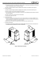
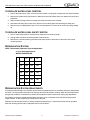
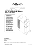
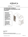
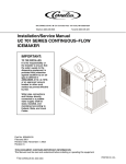
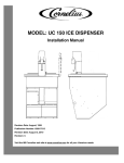
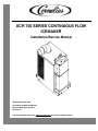
UCR 700 SERIES CONTINUOUS FLOW
ICEMAKER
Installation/Service Manual
Release Date: May, 2001
Publication Number: 630460154
Revision Date: April 02, 2014
Revision: D
Visit the Cornelius web site at www.cornelius.com for all your Literature needs.
The products, technical information, and instructions contained in this manual are subject to change without notice.
These instructions are not intended to cover all details or variations of the equipment, nor to provide for every possible contingency in the installation, operation or maintenance of this equipment. This manual assumes that the person(s) working on the equipment have been trained and are skilled in working with electrical, plumbing, pneumatic,
and mechanical equipment. It is assumed that appropriate safety precautions are taken and that all local safety and
construction requirements are being met, in addition to the information contained in this manual.
This Product is warranted only as provided in Cornelius’ Commercial Warrant applicable to this Product and is subject to all of the restrictions and limitations contained in the Commercial Warranty.
Cornelius will not be responsible for any repair, replacement or other service required by or loss or damage resulting
from any of the following occurrences, including but not limited to, (1) other than normal and proper use and normal
service conditions with respect to the Product, (2) improper voltage, (3) inadequate wiring, (4) abuse, (5) accident,
(6) alteration, (7) misuse, (8) neglect, (9) unauthorized repair or the failure to utilize suitably qualified and trained persons to perform service and/or repair of the Product, (10) improper cleaning, (11) failure to follow installation, operating, cleaning or maintenance instructions, (12) use of “non-authorized” parts (i.e., parts that are not 100%
compatible with the Product) which use voids the entire warranty, (13) Product parts in contact with water or the
product dispensed which are adversely impacted by changes in liquid scale or chemical composition.
Contact Information:
To inquire about current revisions of this and other documentation or for assistance with any Cornelius product contact:
www.cornelius.com
800-238-3600
Trademarks and Copyrights:
This document contains proprietary information and it may not be reproduced in any way without permission from
Cornelius.
Printed in U.S.A.
TABLE OF CONTENTS
Safety Instructions. . . . . . . . . . . . . . . . . . . . . . . . . . . . . . . . . . . . . . . . . . . . . . . . . . . . . . . . . . . . . . . . 1
Read and Follow ALL Safety Instructions . . . . . . . . . . . . . . . . . . . . . . . . . . . . . . . . . . . . . . . . . . . . 1
Safety Overview . . . . . . . . . . . . . . . . . . . . . . . . . . . . . . . . . . . . . . . . . . . . . . . . . . . . . . . . . . . . 1
Recognition . . . . . . . . . . . . . . . . . . . . . . . . . . . . . . . . . . . . . . . . . . . . . . . . . . . . . . . . . . . . . . . . 1
Different Types of Alerts . . . . . . . . . . . . . . . . . . . . . . . . . . . . . . . . . . . . . . . . . . . . . . . . . . . . . . . . . 1
Safety Tips . . . . . . . . . . . . . . . . . . . . . . . . . . . . . . . . . . . . . . . . . . . . . . . . . . . . . . . . . . . . . . . . . . . 1
Qualified Service Personnel . . . . . . . . . . . . . . . . . . . . . . . . . . . . . . . . . . . . . . . . . . . . . . . . . . . . . . 1
Safety Precautions . . . . . . . . . . . . . . . . . . . . . . . . . . . . . . . . . . . . . . . . . . . . . . . . . . . . . . . . . . . . . 2
Shipping and Storage . . . . . . . . . . . . . . . . . . . . . . . . . . . . . . . . . . . . . . . . . . . . . . . . . . . . . . . . . . . 2
General Description . . . . . . . . . . . . . . . . . . . . . . . . . . . . . . . . . . . . . . . . . . . . . . . . . . . . . . . . . . . . . . 3
To the User of this Manual . . . . . . . . . . . . . . . . . . . . . . . . . . . . . . . . . . . . . . . . . . . . . . . . . . . . . . . 3
Description . . . . . . . . . . . . . . . . . . . . . . . . . . . . . . . . . . . . . . . . . . . . . . . . . . . . . . . . . . . . . . . . . . . 3
Claims Instructions . . . . . . . . . . . . . . . . . . . . . . . . . . . . . . . . . . . . . . . . . . . . . . . . . . . . . . . . . . . . . 3
Warranty reference Information . . . . . . . . . . . . . . . . . . . . . . . . . . . . . . . . . . . . . . . . . . . . . . . . . . . 3
Design Data . . . . . . . . . . . . . . . . . . . . . . . . . . . . . . . . . . . . . . . . . . . . . . . . . . . . . . . . . . . . . . . . . . 3
Specification Chart . . . . . . . . . . . . . . . . . . . . . . . . . . . . . . . . . . . . . . . . . . . . . . . . . . . . . . . . . . . . . 4
Installation . . . . . . . . . . . . . . . . . . . . . . . . . . . . . . . . . . . . . . . . . . . . . . . . . . . . . . . . . . . . . . . . . . . . . . 6
Pre-Installation . . . . . . . . . . . . . . . . . . . . . . . . . . . . . . . . . . . . . . . . . . . . . . . . . . . . . . . . . . . . . . . . 6
Freight Damage Claim . . . . . . . . . . . . . . . . . . . . . . . . . . . . . . . . . . . . . . . . . . . . . . . . . . . . . . . 6
Counter . . . . . . . . . . . . . . . . . . . . . . . . . . . . . . . . . . . . . . . . . . . . . . . . . . . . . . . . . . . . . . . . . . . 6
Electrical . . . . . . . . . . . . . . . . . . . . . . . . . . . . . . . . . . . . . . . . . . . . . . . . . . . . . . . . . . . . . . . . . . 6
Drain . . . . . . . . . . . . . . . . . . . . . . . . . . . . . . . . . . . . . . . . . . . . . . . . . . . . . . . . . . . . . . . . . . . . . 6
Installation . . . . . . . . . . . . . . . . . . . . . . . . . . . . . . . . . . . . . . . . . . . . . . . . . . . . . . . . . . . . . . . . . . . . 6
Initial Start up, Checks and Adjustment Instructions . . . . . . . . . . . . . . . . . . . . . . . . . . . . . . . . . . . . 8
Guide to service . . . . . . . . . . . . . . . . . . . . . . . . . . . . . . . . . . . . . . . . . . . . . . . . . . . . . . . . . . . . . . . . . 9
Icemaker Cleaning and Sanitizing Procedures . . . . . . . . . . . . . . . . . . . . . . . . . . . . . . . . . . . . . . . . 9
Maintenance . . . . . . . . . . . . . . . . . . . . . . . . . . . . . . . . . . . . . . . . . . . . . . . . . . . . . . . . . . . . . . . . . . 9
Monthly . . . . . . . . . . . . . . . . . . . . . . . . . . . . . . . . . . . . . . . . . . . . . . . . . . . . . . . . . . . . . . . . . . . 9
Quarterly . . . . . . . . . . . . . . . . . . . . . . . . . . . . . . . . . . . . . . . . . . . . . . . . . . . . . . . . . . . . . . . . . . 9
Semi-Annually . . . . . . . . . . . . . . . . . . . . . . . . . . . . . . . . . . . . . . . . . . . . . . . . . . . . . . . . . . . . . 10
Water Level Control . . . . . . . . . . . . . . . . . . . . . . . . . . . . . . . . . . . . . . . . . . . . . . . . . . . . . . . . . . . 10
How Water Level Control Works . . . . . . . . . . . . . . . . . . . . . . . . . . . . . . . . . . . . . . . . . . . . . . . 10
Purpose . . . . . . . . . . . . . . . . . . . . . . . . . . . . . . . . . . . . . . . . . . . . . . . . . . . . . . . . . . . . . . . . . . 10
To Replace Water Level Control . . . . . . . . . . . . . . . . . . . . . . . . . . . . . . . . . . . . . . . . . . . . . . . 11
To Replace Water Level Safety Switch . . . . . . . . . . . . . . . . . . . . . . . . . . . . . . . . . . . . . . . . . . 11
Refrigeration System . . . . . . . . . . . . . . . . . . . . . . . . . . . . . . . . . . . . . . . . . . . . . . . . . . . . . . . . . . 11
Refrigeration System Adjustments . . . . . . . . . . . . . . . . . . . . . . . . . . . . . . . . . . . . . . . . . . . . . . . . 11
Expansion Valve . . . . . . . . . . . . . . . . . . . . . . . . . . . . . . . . . . . . . . . . . . . . . . . . . . . . . . . . . . . . . . 12
Adjustment and Troubleshooting . . . . . . . . . . . . . . . . . . . . . . . . . . . . . . . . . . . . . . . . . . . . . . . . . 12
Condenser Modulating Valve . . . . . . . . . . . . . . . . . . . . . . . . . . . . . . . . . . . . . . . . . . . . . . . . . . . . 12
Condenser Modulating Valve Removal . . . . . . . . . . . . . . . . . . . . . . . . . . . . . . . . . . . . . . . . . . . . . 13
Bin Control . . . . . . . . . . . . . . . . . . . . . . . . . . . . . . . . . . . . . . . . . . . . . . . . . . . . . . . . . . . . . . . . . . 13
Gearmotor . . . . . . . . . . . . . . . . . . . . . . . . . . . . . . . . . . . . . . . . . . . . . . . . . . . . . . . . . . . . . . . . . . . 14
Motor Check . . . . . . . . . . . . . . . . . . . . . . . . . . . . . . . . . . . . . . . . . . . . . . . . . . . . . . . . . . . . . . . . . 15
Start Relay . . . . . . . . . . . . . . . . . . . . . . . . . . . . . . . . . . . . . . . . . . . . . . . . . . . . . . . . . . . . . . . . . . 15
To Replace Gearmotor Assembly . . . . . . . . . . . . . . . . . . . . . . . . . . . . . . . . . . . . . . . . . . . . . . 15
Auger and Extruding Head Removal . . . . . . . . . . . . . . . . . . . . . . . . . . . . . . . . . . . . . . . . . . . . . . 16
Installation and Shaft Seal Replacement . . . . . . . . . . . . . . . . . . . . . . . . . . . . . . . . . . . . . . . . . . . 16
Upper Nut and Bearing Assembly . . . . . . . . . . . . . . . . . . . . . . . . . . . . . . . . . . . . . . . . . . . . . . . . . 16
To Replace Bearing . . . . . . . . . . . . . . . . . . . . . . . . . . . . . . . . . . . . . . . . . . . . . . . . . . . . . . . . 17
Electrical Checkout . . . . . . . . . . . . . . . . . . . . . . . . . . . . . . . . . . . . . . . . . . . . . . . . . . . . . . . . . . . . 17
Overload Check . . . . . . . . . . . . . . . . . . . . . . . . . . . . . . . . . . . . . . . . . . . . . . . . . . . . . . . . . . . . . . . 17
Compressor Check . . . . . . . . . . . . . . . . . . . . . . . . . . . . . . . . . . . . . . . . . . . . . . . . . . . . . . . . . . . . 17
Capacitor Check . . . . . . . . . . . . . . . . . . . . . . . . . . . . . . . . . . . . . . . . . . . . . . . . . . . . . . . . . . . . . . 18
Safety Controls . . . . . . . . . . . . . . . . . . . . . . . . . . . . . . . . . . . . . . . . . . . . . . . . . . . . . . . . . . . . . . . 18
Troubleshooting . . . . . . . . . . . . . . . . . . . . . . . . . . . . . . . . . . . . . . . . . . . . . . . . . . . . . . . . . . . . . . . . 23
Troubleshooting Compressors . . . . . . . . . . . . . . . . . . . . . . . . . . . . . . . . . . . . . . . . . . . . . 23
Parts List . . . . . . . . . . . . . . . . . . . . . . . . . . . . . . . . . . . . . . . . . . . . . . . . . . . . . . . . . . . . . . . . . . . . . . 24
UCR 700 Series Continuous Flow Icemaker Installation/ServiceManual
SAFETY INSTRUCTIONS
READ AND FOLLOW ALL SAFETY INSTRUCTIONS
Safety Overview
•
Read and follow ALL SAFETY INSTRUCTIONS in this manual and any warning/caution labels on the unit (decals, labels or
laminated cards).
•
Read and understand ALL applicable OSHA (Occupational Safety and Health Administration) safety regulations before
operating this unit.
Recognition
Recognize Safety Alerts
!
This is the safety alert symbol. When you see it in this manual or on the unit,
be alert to the potential of personal injury or damage to the unit.
DIFFERENT TYPES OF ALERTS
Indicates an immediate hazardous situation which if not avoided WILL result in serious injury, death or equipment
damage.
! WARNING:
Indicates a potentially hazardous situation which, if not avoided, COULD result in serious injury, death, or equipment
damage.
! CAUTION:
Indicates a potentially hazardous situation which, if not avoided, MAY result in minor or moderate injury or equipment
damage.
SAFETY TIPS
•
Carefully read and follow all safety messages in this manual and safety signs on the unit.
•
Keep safety signs in good condition and replace missing or damaged items.
•
Learn how to operate the unit and how to use the controls properly.
•
Do not let anyone operate the unit without proper training. This appliance is not intended for use by very young children or
infirm persons without supervision. Young children should be supervised to ensure that they do not play with the appliance.
•
Keep your unit in proper working condition and do not allow unauthorized modifications to the unit.
QUALIFIED SERVICE PERSONNEL
! WARNING:
Only trained and certified electrical, plumbing and refrigeration technicians should service this unit. ALL WIRING AND
PLUMBING MUST CONFORM TO NATIONAL AND LOCAL CODES. FAILURE TO COMPLY COULD RESULT IN
SERIOUS INJURY, DEATH OR EQUIPMENT DAMAGE.
Publication Number: 630460154
-1-
© 2001-2014, Cornelius Inc.
UCR 700 Series Continuous Flow Icemaker Installation/Service Manual
SAFETY PRECAUTIONS
This unit has been specifically designed to provide protection against personal injury. To ensure continued protection
observe the following:
! WARNING:
Disconnect power to the unit before servicing following all lock out/tag out procedures established by the user. Verify
all of the power is off to the unit before any work is performed.
Failure to disconnect the power could result in serious injury, death or equipment damage.
! CAUTION:
Always be sure to keep area around the unit clean and free of clutter. Failure to keep this area clean may result in
injury or equipment damage.
SHIPPING AND STORAGE
! CAUTION:
Before shipping, storing, or relocating the unit, the unit must be sanitized and all sanitizing solution must be drained
from the system. A freezing ambient environment will cause residual sanitizing solution or water remaining inside the
unit to freeze resulting in damage to internal components.
© 2001-2014, Cornelius Inc.
-2-
Publication Number: 630460154
UCR 700 Series Continuous Flow Icemaker Installation/ServiceManual
GENERAL DESCRIPTION
TO THE
USER OF THIS MANUAL
This manual covers the installation and assembly of the Air--Cooled or Water--Cooled Model UC700 Icemaker with
the Model UC150 Dispenser. Refer to Table of Contents for page location of detailed information pertaining to
questions that may arise during installation or operation of this equipment.
DESCRIPTION
The UC700 is a chuncklet Icemaker designed to be installed under a counter adjacent to an Ice Dispenser or an Ice
Storage Bin. The Icemaker will deliver ice to either the left or right side. The Icemaker requires a 12--inch by 12-inch opening at the lower front of the Unit for air intake. A minimum of 1.5 sq. ft. opening must be provided out the
left or right side and the rear of the machine for air exhaust.
CLAIMS INSTRUCTIONS
Claims: In the event of shortage, notify the carrier as well as Cornelius immediately. In the event of damage, notify
the carrier. Cornelius is not responsible for damage occurring in transit, but will gladly render assistance necessary
to pursue your claim. Merchandise must be inspected for concealed damage within 15 days of receipt.
WARRANTY REFERENCE INFORMATION
Warranty Registration Date
(to be filled out by customer)
Unit Part Number:
Serial Number:
Install Date:
Local Authorized Service Center:
DESIGN DATA
Table 1. Design Date
Unit Model Number:
UCR700--A Series Continuous--Flow Icemaker (Air--Cooled)
UCR700--W Series Continuous--Flow Icemaker (Water--Cooled)
Unit Overall Dimensions:
Height
27 inchs
Width
15.7 inchs
Depth
25.5 inchs
Clearances Dimensions Required:
Front Side Service Access (Removable front panel to allow removal of Unit)
25 inches
Side Opposite Storage Bin for Air Exhaust
4 inchs
Rear for Air Exhaust
Weights:
Shipping Weight
Publication Number: 630460154
184 pounds
-3-
© 2001-2014, Cornelius Inc.
UCR 700 Series Continuous Flow Icemaker Installation/Service Manual
Table 1. Design Date
Unit Model Number:
Water Supply--Water inlet fitting is 1/4--inch SAE flare located at the top front of the Unit. The Unit is designed to
operate on water pressure between 10 PSI and 90 PSI.
Drain Overflow Line (Located at rear of the Unit)
3/8--inch Flexible Tubing
Ambient Operating Temperature
40° F to 100° F
Electrical:
Unit Electrical Rating
115 VAC, 60 Hz, 15.6 Amps,
Single Phase
Recommended Electrical Supply
115 VAC, 60 hz, 20 Amps
Dedicated 3--Wire Grounded
Circuit
SPECIFICATION CHART
VAC
UCR700--A
Air Cooled
115
60
1
2
12
1.6
2
24
R404A
20
UCR700--W
Water Cooled
115
60
1
2
12
N/A
2
13
R404A
20
© 2001-2014, Cornelius Inc.
HZ
PH
Wire
-4-
Comp.
RLA
Fan
Amps
GRMTR
Amps
Refrigerant
Condensing
Unit
Models
Oz.
Type
Circuit
Fuse
Publication Number: 630460154
UCR 700 Series Continuous Flow Icemaker Installation/ServiceManual
Figure 1. Clearance Requirements
Publication Number: 630460154
-5-
© 2001-2014, Cornelius Inc.
UCR 700 Series Continuous Flow Icemaker Installation/Service Manual
INSTALLATION
PRE-INSTALLATION
FREIGHT DAMAGE CLAIM
The delivery of your equipment (Frieght Company, Distributor, or dealer) is responsible for loss or damage of your
shipment. All claims must be filed with the deliverer of your equipment. Please follow the steps below to determine
if your shipment is satisfactory or if a claim must be filed:
1. Check the number of products delivered against the number of products listed on the delivery receipt.
Should the totals not match, have the driver note all errors on both copies and both you and the driver sign
and date said notation.
2. Inspect all cartons for visible damage. Open and inspect as required before the driver leaves and have him
or her note any damage on the receipts. All damaged claims must be inspected within 15 days of delivery.
Notify your carrier immediately if concealed damage is found after delivery.
3. Should concealed damage be found when the product is unpacked, retain the packing material and the
product and request an inspection from the deliverer.
4. All claims for loss or damage should be filed at once. Delays in filing will reduce the chance of achieving a
satisfactory resolution to the claim.
COUNTER
1. A flat and level counter space sufficiently strong to support the weight of the Dispenser and the Icemaker.
The Icemaker may be installed on the left or the right side of the Dispenser.
2. General Requirements:
A. The front of the Icemaker must be free of obstructions.
B. Allow a 4--inch minimum clearance between exaust side of the Icemaker and adjacent equipment.
C. A louvered front panel (12--inches X 12--inches) aligned with the air inlet of the Icemaker and adequate
ventilation (1.5 Sq. feet opening) in the counter for exaust air.
D. A removable panel in the counter face (from 2--inches below the top of the counter to the floor, a minimum of 19--inches wide) to allow removal of the Icemaker.
ELECTRICAL
Two separate 20 amp, 120VAC, 60 Hz electrical circuits.
DRAIN
One drain beneath the counter at floor level which will accommodate both the drain from the Icemaker and the
Dispenser.
INSTALLATION
1. Keep unit in the upright position, remove carton and pallet from the Icemaker and inspect for damage. If
any damage is found, file a claim with carrier immediately.
2. Locate startup card either on outside of container or on plastic liner. Fill in proper information and send one
to factory, and other copy to distributor. Postage is prepaid.
3. Install the Dispenser first, following installation instructions supplied with the Dispenser.
4. Remove the two hole plugs from the side of the dispenser.
© 2001-2014, Cornelius Inc.
-6-
Publication Number: 630460154
UCR 700 Series Continuous Flow Icemaker Installation/ServiceManual
A. The plugs are pressed in and sealed with a silastic sealant. To remove pry the outside cap off and then
press the inside plug into the bin. Discard both plugs.
B. Install the icemaker alignment brackets (Supplied with icemaker) to the dispenser (See Figure 2).
5. Install the Icemaker:
A. Install the icemaker alignment brackets (Supplied with icemaker) to the icemaker (See Figure 2).
B. Roll the Icemaker into the cabinet alongside the Dispenser.
C. Level and align the icemaker to the dispenser using the four level adjustment bolts located on the lower
front of the Icemaker.
D. Install the locking bolt on the lower front of the icemaker.
E. Connect drain, power and water.
6. Install transport tube:
A. Insert the ice transport tube through the bin into the transport elbow on the Icemaker. (Note: The icemaker is equipped with a safety switch located at the base of the elbow, this switch will prevent the icemaker from running if the elbow is not properly installed).
B. Align the nylon lock screw on the elbow with the recess on the tube. Install lock screw.
7. Connect bin thermostat:
A. Locate bin thermostat cable supplied with the icemaker (Black cable) and connect to electrical box on
the UCR700 and the receptacle on the side of the dispenser.
Attach to bin Left Side Install
Attach to bin Right Side Install
Figure 2. Side Bracket Installation
Publication Number: 630460154
-7-
© 2001-2014, Cornelius Inc.
UCR 700 Series Continuous Flow Icemaker Installation/Service Manual
INITIAL START UP, CHECKS AND ADJUSTMENT INSTRUCTIONS
NOTE: Do not start Icemaker before completing installation steps on pages 7 and 9.
Turn on water supply (if Icemaker is water cooled turn water on to condenser also) turn on main power switch
(located on top of electrical box), and make the following system checks:
NOTE: If Icemaker will not start be sure water reservoir is full. Low water safety control must be properly
adjusted to start and shut down the Icemaker. If water level drops below bottom of reservoir, the Icemaker
must shut down. Adjustment is made by moving magnet up or down.
Water Level—If necessary adjust float by bending float arm up or down as needed, push float assembly down until
Icemaker stops running. Release float and Icemaker will restart. Keep water in reservoir at level line while the
Icemaker is in operation. (See Figure 3)
Low Water Safety Control—Adjust magnet by bending magnet arm as needed to shut unit down if water level
drops below bottom of reservoir.
Bin Control—Place ice around probe, unit should shut down in one minute. Remove ice from around probe, unit
should start in two minutes.
NOTE: For altitudes over 1000 feet above sea level, adjust range screw (behind end cover). Half turn max.
raises setting 4°F approx.
Inlet Fitting
Band up to raise
water level
Low water Safety
Bend down
to lower water level
Band in this direction
to shutdown unit sooner
Figure 3. Icemaker Float Assembly
Water modulating valve (water cooled units only)—Opening point of condenser water modulating valve should
be set to maintain proper operating pressure in the refrigeration system high side. (see chart on page 13). Closing
point of valve should be set low enough to close valve during compressor stand by periods. To raise, turn
counterclockwise, to lower turn clockwise.
© 2001-2014, Cornelius Inc.
-8-
Publication Number: 630460154
UCR 700 Series Continuous Flow Icemaker Installation/ServiceManual
GUIDE TO SERVICE
! WARNING:
Disconnect electrical power to the Icemaker to prevent personal injury before attempting any internal maintenance.
Only qualified personnel should service internal components or electrical wiring.
ICEMAKER CLEANING AND SANITIZING PROCEDURES
!
CAUTION:
Do not use any of the ice made during cleaning operations. Clean and sanitize ice storage area when cleaning
icemaker.
1. Turn machine off.
2. Shut off water supply.
3. Remove ice from storage bin.
4. Mix approved cleaner (2 gallons as directed). Recommended cleaner: Calgon Corp. of Virginia Chemicals,
ice machine cleaner. Mixture: 3-1/3 ounces per gallon of water.
5. Clean auger assembly and ice transition tube in a sink using cleaner mixture and reinstall in icemaker.
6. Turn machine on and add cleaner solution to water level control until 2 gallons have been used.
7. Turn on water supply and run machine for 15 minutes.
8. Turn off machine and remove all ice.
9. Sanitize using household liquid bleach (50 ppm chlorine). Mixture: 1 fluid ounce per gallon room temperature water. 2 minute exposure time.
10. Sanitize auger assembly and ice transition tube in a sink using sanitizing solution and reinstall in icemaker.
11. Fill icemaker with sanitizer by slowly pouring solution into water feed reservoir until full. Solution will drain
through overflow tube. Do not run machine. Allow to air dry.
12. If icemaker is used in conjunction with ice dispenser or storage bin, follow manufacturer’s recommended
cleaning instructions at this time.
MAINTENANCE
Preventive maintenance can increase the trouble free life of your icemaker. Many authorized service agencies offer
service contracts for your icemaker. Contact your local distributor for further information.
MONTHLY
1. Clean the condenser. Use a brush, vacuum cleaner or blow from inside with air or CO2gas.
2. Inspect water feed reservoir at lease once a month until a definite pattern for cleaning and sanitizing has
been established.
QUARTERLY
This is the maximum period of time between cleaning and sanitizing the icemaker. In addition to recommended
monthly procedure, and if a more frequent cleaning and sanitizing pattern has not been established, unit must be
cleaned and sanitized.
Publication Number: 630460154
-9-
© 2001-2014, Cornelius Inc.
UCR 700 Series Continuous Flow Icemaker Installation/Service Manual
SEMI-ANNUALLY
Semi-Annually in addition to all previously established service procedures perform the following:
1. Check for water leaks in tube connections, water fittings and lower Icemaker water seal.
2. Check drain tubes for clogs and aged tubes. Replace if tubes are stained or brittle.
3. Check for signs of condensation. Clean where necessary and replace insulation properly.
4. Check safety circuits for proper operation.
5. Check refrigeration system (see page 11).
6. Check unit for abnormal noise. Tighten machine and cabinet screws, if necessary.
7. Check white upper bearings on auger assembly. If bearings are less than 1/16’’ thick, replace. See Figure 4
Replace
OK
1/16”
1/16”
OK
Replace
Figure 4. Upper Nut and Bearing Assembly
WATER LEVEL CONTROL
HOW WATER LEVEL CONTROL WORKS
When water is introduced through the inlet fitting the float rises. the float pushes against a lever which in turn forces
the poppet assembly against the inlet fitting valve seat which seals the water off. SeeFigure 3 Before the water inlet
is sealed the safety switch is operated. In the event of a water failure the float would drop down and operate the
safety switch to shut off the machine.
If water level control will not shut off and seal at level as indicated, be sure inlet pressure does not exceed
recommended factory operating range.
Under ordinary circumstances adjustment should not be necessary providing it was properly adjusted when unit
was installed or relocated. If, however, the control becomes inoperative, repair or replace. See Start-Up
Adjustment, page 9.
PURPOSE
1. To automatically maintain proper water level in the evaporator when unit is running and making ice.
2. A safety switch is operated in the event of an interruption in water supply. The switch shuts off the electrical
power to the icemaker and its refrigeration system. Switch will reset as soon as cause of water failure has
been corrected and proper water level in icemaker has again been reached.
3. The transparent bowl not only provides a visible check of water level, but also is a good guide to the internal conditions which exist within the icemaker assembly itself. (See Cleaning Procedure.)
© 2001-2014, Cornelius Inc.
- 10 -
Publication Number: 630460154
UCR 700 Series Continuous Flow Icemaker Installation/ServiceManual
TO REPLACE WATER LEVEL CONTROL
1. Shut off the water supply. Shut off the main power switch or unplug the ice dispenser from electrical outlet.
2. Remove the flexible tubing from bottom of water level control and drain water from water level control and
evaporator.
3. Remove flexible tubing at bottom of water level bowl connected to the overflow.
4. Hold water inlet fitting with proper tool to prevent it from rotating when disconnecting the water inlet.
5. Remove wing nut holding water control to its mounting bracket. Control can be removed by lifting straight
up.
TO REPLACE WATER LEVEL SAFETY SWITCH
1. Shut off main power switch or unplug the ice dispenser from electrical outlet.
2. Unplug molex connector connecting switch to electrical box.
3. Remove the 2 screws anchoring the water level safety switch to the bottom of the water level control
mounting bracket.
REFRIGERATION SYSTEM
NOTE: Thermostatic Expansion Valve No Adjustment
±10 Lbs Discharge Pressure
WATER TEMPERATURE
A
I
R
T
E
M
P
40°
65°
90°
50°
174
177
180
60°
202
205
208
70°
230
233
236
80°
265
269
272
90°
300
304
307
100°
328
334
340
REFRIGERATION SYSTEM ADJUSTMENTS
A complete understanding of the icemaker and hermetic refrigeration system is necessary before any adjustments
are made. The refrigeration technician must use high and low side pressure readings, water and air temperatures,
plus general conditions of cleanliness to assess the refrigeration system status when making any adjustments.
All icemaker products are tested and adjusted at the factory prior to shipment where the ambient temperature
ranges from 65° to 90°F, depending on the season of the year.
Whenever a new icemaker product is initially installed and started-up, it is imperative that the start-up operation
make the following checks and/or readjustments for local conditions.
Publication Number: 630460154
- 11 -
© 2001-2014, Cornelius Inc.
UCR 700 Series Continuous Flow Icemaker Installation/Service Manual
EXPANSION VALVE
You will find a thermostatic expansion valve on icemakers, which is used to control the amount of refrigerant flowing
through the evaporator. Improperly installed or defective expansion valves may cause low production, soft ice,
squeaking from evaporator and excessive load inside evaporator.
By using general refrigeration system troubleshooting along with the pressure charts you can easily determine
whether or not the expansion valve is working properly.
ADJUSTMENT AND TROUBLESHOOTING
When troubleshooting the expansion valve you must first be sure you have adequate water flowing into evaporator,
a clean condenser, unit is properly ventilated, and system is properly charged and free from any restrictions. Also
be sure compressor is operating properly.
Second, take reservoir water temperature and air temperature from condenser inlet and determine at what
pressure unit should be running. Machines are equipped with thermostatic valves, there is NO adjustment. If
correct pressure cannot be obtained, first be sure system has time to stabilize 10-15 minutes. Second, be sure
sensing bulb is located at 12:00 position on outlet side of evaporator about 3-4 inches away from evaporator and be
sure to insulate well and clamp tightly to tubing. If system pressures are still not adequate, take a second water and
air temperature reading and go over other parts of system for possible problems. If proper charge is questionable
evacuate and recharge to nameplate and leak check. If valve still malfunctions replace valve. When replacing valve
be sure to bleed refrigerant gas from low side port so as not to lose refrigerant oil. Use general refrigerant system
practices when replacing and recharging unit. After new valve is in place, go through previous monitored
adjustments and troubleshooting to be sure valve is functioning properly.
NOTE: Units with thermostatic expansion valve—The valve is located on bottom refrigerant line. Sensing
bulb is located on top refrigerant line. On water cooled units adjust condenser modulating valve before
troubleshooting expansion valve.
! CAUTION:
Very high discharge pressure is present in system. Quick disconnects on your gauges will minimize danger and loss
of refrigerant. Comply with federal regulations for reclaiming refrigerant.
CONDENSER MODULATING VALVE
The reason for using a water modulating valve is to supply the correct amount of water to the condenser. and to
maintain a proper operating pressure to refrigeration system high side.
The flow of water through the valve is increased as the high side pressure rises and is decreased as high side
pressure lowers.To calibrate the amount of water flow with the refrigeration system high side pressure, turn
adjustment screw located on end of valve opposite of bellows. See Figure 6. Turn screw counterclockwise to raise
opening point or clockwise to lower opening point. Opening point of valve should be set to maintain proper
operating pressure in refrigeration system high side. Refer to Pressure Chart on page 3. Closing point of valve
should be set low enough to close valve during compressor stand-by periods.
NOTE: Cold water will absorb heat faster than warm water. The water flow will therefore automatically
increase as inlet temperature increases.
Sight Glass
Thermostatic
Expansion Valve
Figure 5. Expansion Valve
© 2001-2014, Cornelius Inc.
Figure 6. Adjustment Screw
- 12 -
Publication Number: 630460154
UCR 700 Series Continuous Flow Icemaker Installation/ServiceManual
CONDENSER MODULATING VALVE REMOVAL
1. Disconnect power to unit, then shut off water supply to condenser and evacuate refrigerant from system.
2. Remove inlet water line from Condenser Modulating Valve. Also remove tube from high side refrigerant
line.
3. Remove Condenser Modulating Valve and bracket from unit.
4. Remove valve from bracket.
5. Replace Condenser Modulating Valve by reversing Steps 2 thru 4. Then pull system into vacuum.
6. Charge unit with proper amount of refrigeration.
7. Turn power and water on to unit.
8. With unit running, adjust modulating valve to proper setting.
9. Go through a complete system check.
BIN CONTROL
The type of bin control used on all UC Models is thermostatically controlled. The switch itself is inside the electrical
box of the Dispenser and can be serviced from the front of the unit. The cap tube bulb is located in the thermostat
well directly under the ice inlet.
To test switch, disconnect power to unit and remove one wire from switch. Connect both leads of your ohmmeter to
the Bin Control Switch terminals. With control bulb at room temperature ohmmeter should read “Closed Circuit”.
Now cover the control bulb with ice, within 1 minute switch should “click” and ohmmeter should read “Open Circuit.”
The Bin control is in electrical series with a 24 volt transformer located in the ice dispenser and a 24 volt control
relay located in the Icemaker.
The Bin 24 volt control relay is in electrical series with coil on antifreeze relay along with the low water safety. If unit
is water cooled, the condenser high pressure cut out is also in series.
The Control Switch is held in place inside electrical box by 2 screws. Control bulb is positioned under ice chute and
can be replaced by removing the capillary from the thermostat well.
The most important thing to remember when replacing probe is to be careful not to cut or kink probe and be sure
sensor bulb is located in a position to shut unit down before ice reaches ice chute.
This icemaker is equipped with a safety ice level sensor. This sensor control is located on top of theevaporator.This
switch is also in electrical series with the anti-freeze relay and other safety circuitry.
Publication Number: 630460154
- 13 -
© 2001-2014, Cornelius Inc.
UCR 700 Series Continuous Flow Icemaker Installation/Service Manual
GEARMOTOR
The gearmotor is equipped with a start relay and a manual reset overload.
When current is applied, the relay energizes and completes the circuit to the start winding. The motor reaches a
predetermined speed and the relay drops out, disconnecting the start winding. The run winding remains in the
circuit as long as current is applied.
The purpose of the overload is to automatically shut off the motor in the event of a mechanical bind of the
transmission, an overload condition within the evaporator or an electrical malfunction. It does this by sensing
amperage draw. If the motor stalls the start relay would energize and stay energized. The amperage would surge 5
to 6 times greater than the normal draw. In this event the overload would shut off the transmission in 4 to 8
seconds.
If the motor is subjected to an abnormal load, but does not reach a stall condition, the overload will react, but over
a greater period of time. The reaction time depends upon the amperage to which it is subjected.
The overload, through the safety circuit, also shuts off the compressor.
© 2001-2014, Cornelius Inc.
- 14 -
Publication Number: 630460154
UCR 700 Series Continuous Flow Icemaker Installation/ServiceManual
MOTOR CHECK
The resistance readings on the winding will be between 5 to 25 ohms. A meter capable of these low readings must
be used. The start relay cover must be removed. (See Figure 7).
If no continuity on start or run winding test, replace gearmotor. If continuity on grounded motor test, replace
gearmotor.
START RELAY
1. Check between “2” and “4” on relay (with relay unplugged). If there is continuity replace the relay, as the
relay contacts should be open.
2. Check between “3” and “4” on relay, if no continuity replace the relay.
Figure 7. Gearmotor Assembly
TO REPLACE GEARMOTOR ASSEMBLY
1. Disconnect the icemaker from the electrical power source.
2. Disconnect the transmission cable from the electrical box.
3. Remove the 4 hex head bolts securing the evaporator to the top of the transmission.
4. Remove the 4 bolt’s holding the transmission and bracket to frame base, while supporting the weight of the
evaporator. Remove the transmission from the unit.
5. When replacing the transmission, it may be necessary to rotate the auger back and forth to align the motor
shaft and auger.
Auger Nut
Bearing Delrin
Bearing Nylon
Auger
“D” Drive
Groove
Extruding Head
Anti‐‐rotation RIB ‐‐ 3 Places
Figure 8. Auger and Extruding Head Removal
Publication Number: 630460154
- 15 -
© 2001-2014, Cornelius Inc.
UCR 700 Series Continuous Flow Icemaker Installation/Service Manual
AUGER AND EXTRUDING HEAD REMOVAL
1. Disconnect unit from power supply.
2. Remove storage container cover and put aside.
3. Turn off water supply to icemaker.
4. After ice has melted from head take hold of the auger nut and lift straight up to disengage from icemaker.
5. When replacing the auger assembly, make certain that both the auger engages the output shaft drive and
the extruding head ribs engage the evaporator tube. (See Figure 8)
E‐‐Ring
Washer, Plain Flat
Shaft Seal
Mount, Shaft Seal
Seat, Shaft Seal
Gearmotor
Figure 9.Shaft Seal
INSTALLATION AND SHAFT SEAL REPLACEMENT See (Figure 9)
1. Place shaft seal locator seat and shaft seal mount over gearmotor output shaft and push down until shaft
seal seat and shaft seal mount rest flush on top of gearmotor.
2. Place rubber coated ceramic seal (important: ceramic face up) over output shaft and push down until seal
nest in recess of shaft seal mount. (lubricate rubber on ceramic seal with rubber lubricant).
3. Place shaft seal with carbon face down (spring up) over output shaft and push (gently) downward until seal
rests on carbon face of the output shaft seal.
4. Place flat washer over output shaft and let rest on the output shaft seal. Push down on the washer compressing the spring on the output shaft seal. While holding the seals (down) in place slide the E-ring into
the groove on the output shaft.
UPPER NUT AND BEARING ASSEMBLY
The upper white bearing located on top of the auger is used to absorb the force between the auger and extruding
head.
NOTE: The bearings are 3/32” thick. When they wear below 1/16” they should be replaced. Bearings to be
inspected for wear during quarterly maintenance. (See Figure 4)
© 2001-2014, Cornelius Inc.
- 16 -
Publication Number: 630460154
UCR 700 Series Continuous Flow Icemaker Installation/ServiceManual
TO REPLACE BEARING
1. Disconnect unit from electric power.
2. Remove top panels.
3. Remove Dispense Tray Cover.
4. Use an open end wrench on auger nut connected to bearing and turn counterclockwise to remove assembly.
5. Remove worn bearings. Replace with new bearings and then reinstall assembly.
NOTE: If auger turns with nut, remove cover on top of gearmotor stator and hold motor while loosening
nut.
Overload
Ground
Figure 10. Overload Check
Figure 11. Compressor Check
ELECTRICAL CHECKOUT
1. Be sure the unit is disconnected from the power source. Remove the compressor electrical box cover.
Check for obvious damage and loose wires.
2. Disconnect the fan motor leads. Since capacitors store energy, short the capacitor with a screwdriver. This
will prevent shocks.
3. Disconnect the compressor terminal wires.
OVERLOAD CHECK (See Figure 10)
Using a volt-ohmmeter check the continuity across the overload, contact #1 and # 3. If none, wait for unit to cool
down and try again. If still no continuity, the overload protector is defective and should be replaced.
COMPRESSOR CHECK (See Figure 11)
The resistance readings on the windings will be between 0.25 to 10.00 ohms, a meter capable of these low
readings must be used.
1. Check between “C” and “R.” Replace the compressor if there is no continuity as the run windings are open.
2. Check between “C” and “S.” Replace the compressor if there is no continuity as the start windings are
open.
3. Check between “C” and “R” or “S” and the shell of the compressor. If there is continuity, replace the compressor as the motor is grounded.
4. Check between screw terminal on the overload and “C” on the compressor. Check and repair the lead or
connections if there is no continuity.
Publication Number: 630460154
- 17 -
© 2001-2014, Cornelius Inc.
UCR 700 Series Continuous Flow Icemaker Installation/Service Manual
CAPACITOR CHECK
1. Check or replace start capacitor, disconnect bleed resistor before checking for shorted capacitor.
2. Check or replace run capacitor (if supplied) check for shorted capacitor or either terminal grounded to
case.
WARNING
DO NOT PRESS RESET IF REFRIG UNIT
IS RUNNING OR ICEMAKER IS FROZEN
Figure 12. Gear Motor Overload
SAFETY CONTROLS
Your icemaker unit has several safety and control devices incorporated into its design.
! WARNING:
None of the below described devices should ever be “bypassed” to allow the unit to function.
The safety and control system shut-off devices are:
1. Low water shut off reed switch located in icemaker float assembly. (Automatic reset type.) See Figure 3
2. Gearmotor thermal overload, manual reset type (red button on motor). See Wiring Diagram Figure 13.
3. Compressor thermal overload, automatic reset type. See Figure 10
4. Anti-freeze relay and associated circuit. See Wiring Diagram Figure 13.
5. Main service switch located on top of the control box. See Wiring diagram Figure 13.
6. Bin Control.
7. High pressure cut out (water cooled only).
© 2001-2014, Cornelius Inc.
- 18 -
Publication Number: 630460154
UCR 700 Series Continuous Flow Icemaker Installation/ServiceManual
Publication Number: 630460154
- 19 -
© 2001-2014, Cornelius Inc.
UCR 700 Series Continuous Flow Icemaker Installation/Service Manual
Figure 13. Wiring Diagram
© 2001-2014, Cornelius Inc.
- 20 -
Publication Number: 630460154
UCR 700 Series Continuous Flow Icemaker Installation/ServiceManual
Figure 14. Wiring Diagram 240V
Publication Number: 630460154
- 21 -
© 2001-2014, Cornelius Inc.
UCR 700 Series Continuous Flow Icemaker Installation/Service Manual
© 2001-2014, Cornelius Inc.
- 22 -
Publication Number: 630460154
UCR 700 Series Continuous Flow Icemaker Installation/ServiceManual
TROUBLESHOOTING
IMPORTANT: Only qualified personnel should service internal components or electrical wiring.
TROUBLESHOOTING COMPRESSORS
Trouble
Probable Cause
Remedy
Basically the compressor problems can be narrowed down to three areas of checkout.
A. No voltage to the compressor terminals.
A. Check circuit.
B. Below 90% of nameplate rated voltage.
THE COMPRESSOR WILL
NOT RUN
B. Low voltage.
C. Problems in the compressor electrical circuit.
C. See electrical checkout instructions.
THE COMPRESSOR STARTS BUT
TRIPS REPEATEDLY ON THE
OVERLOAD PROTECTOR
A.
A. Check for proper fan
operation and clean
condenser.
B.
C. Voltage.
D. High compressor
amperage draw.
B. Check the compressor
suction and discharge pressures.
C. Voltage should be
within 10% of the
rated nameplate voltage.
D. It should never exceed
120% of the rated
nameplate amperage.See electrical
checkout instructions.
THE COMPRESSOR RUNS BUT
WILL NOT REFRIGERATE
Publication Number: 630460154
A. Compressor not working
- 23 -
A. Check the compressor
suctions and discharge pressures.
See chart on page 11.
© 2001-2014, Cornelius Inc.
UCR 700 Series Continuous Flow Icemaker Installation/Service Manual
PARTS LIST
Figure 15. Cabinet Section Exploded View
Item
No.
Part No.
Name
Item
No.
Part No.
Name
1
07578
Thread Cutting Screw, Phil Truss
Hd.No. 8--32 X 3/8--in long
11
630000908
Brkt Wld Asy Rear Bin
2
630000806
Panel Top
12
630200868
Brkt Chassis Alignment Fnt
3
13
630200876
Brkt Bin Alignment Rear
4
14
630200735
Cover Elec Box
5
630000808
Panel, Left--Hand
15
630250094
Line Water Inlet
6
630000807
Panel, Right--Hand
16
638008409
Fitting Bulkhead
7
630201094
Panel, Back
17
638007206--04
Nut Jam 1/2--20
8
161176000
Washer, Flat, .250 I.D.
18
638007276--01
Nut 10A or Z Tinn
9
161179001
Bolt MA 1/4--20 X 5/8--In Long
19
638007972--01
Screw Sm #10 X 3/4 HX
10
630000907
Brkt Wld Asy Fnt Bin
20
630250091
Service Valve Assy
Publication Number: 630460154
- 24 -
© 2001-2014, Cornelius Inc.
UCR 700 Series Continuous Flow Icemaker Installation/Service Manual
Item
No.
Part No.
Name
1
38220
Machine Screw, 1/4-20
2
630000741
Elbow, Ice Chute
3
630250106
Tube, Ice Transfer
4
630900564
O-Ring, 4.234 I.D.
5
630900608
Head, Extruder
6
638090213
Auger
7
638090219
Bearing, Nylon
8
638090220
Bearing, Delrin
9
638090211-002
Auger Nut
Figure 16. Ice Chute Components
Item
No.
Part No.
Name
1
161168017
Machine Screw, Phil Pan Hd, No.
6-32 By 1/4-In. Long
2
630900547
Water Level Control
3
638004717
Bracket, Water Level Control
4
638006070
Tube, .375 I.D.
5
638006070
Tube, .375 I.D.
6
638008483-05
Reed Switch Ass’y
Figure 17. Water Level Control Components.
© 2001-2014, Cornelius Inc.
- 25 -
Publication Number: 630460154
UCR 700 Series Continuous Flow Icemaker Installation/Service Manual
Item
No.
Part No.
Name
1
03611
Snap Bushing
2
07578
Thread Cutting Screw, Phil Truss Hd,
No. 8-32 By 3/8-In. Long
161165008
Capacitor, Start 115V
25335
Capacitor, Start 230V
4
161168005
Thread Cutting Screw, Hex Hd, No.
8-32 By 1/2-In. Long
5
161192004
Capacitor, Run
161998009
Relay, Start Capacitor 115V
161998015
Relay, Start Capacitor 230V
7
164083001
Hex Nut, No. 6-32
8
630000599
Wrap
9
630200166
Strap, Capacitor
10
630900111
Thread Cutting Screw, Phil Pan Hd,
No. 8-32 By 3/4-In. Long
638003898
Relay 115V
3
6
11
638010002
Relay 230V
12
638004791
Switch, Toggle
13
638030047
Relay, 24V 10Amp
638090052
Relay 115V
638090054
Relay 230V
14
15
63800700902
Thread Cutting Screw, Phil Pan Hd,
No. 6 By 3/8-In. Long
Figure 18. Electrical Box Components
Item
No.
Part No.
Name
Compressor Components
1
164154001
Washer, Flat, >375 I.D.
2
165596002
Grommet
3
168770002
Machine Screw, Hex Hd, 5/16-18 By
1 1/2-In. Long
631500018
Compressor Kit 115V
631500018
Compressor Kit 230V
638007972-02
Hex Washer Hd, No. 10 By 1/2-In.
Long
4
5
Figure 19. Compressor Components
Publication Number: 630460154
- 26 -
© 2001-2014, Cornelius Inc.
UCR 700 Series Continuous Flow Icemaker Installation/Service Manual
Item
No.
Part No.
Name
1
161179001
Machine Screw, Hex Hd, 1/2-20
By 5/8-In. Long
2
168833000
Washer, Lock, .255 I.D.
3
168833002
Washer
4
311462000
Machine Screw, Hex Hd, 5/16-18
By 1/2-In. Long
5
630000651
Evaporator Tube
6
30201088
Bracket, Front End
7
630900128
Thread Cutting Screw, Sl Hex Hd,
No. 10-32 By 3/8-In. Long
8
638005406
Shield, Motor
9
638031027
O-Ring
10
638090051
Seal, Shaft
11
638090053
E-Ring
12
638090215
Mount, Shaft Seal
13
638090216
Seat, Shaft Seal
14
638007026-01
Machine Screw, Phil Pan Hd, No.
8-32 By 3/8-In. Long
15
638007301-030
Washer, Flat, 1.01 I.D.
638090001
Gear Motor 115V
630900422
Gear Motor 230V
16
Figure 20. Front End Components
Item
No.
Part No.
Name
1
00258
Speed Nut, 1/4-20
2
03612
Machine Screw, Hex Hd, No. 8-36
By 1/2-In. Long
3
08822
Cushion
4
5
6
638090009
Bracket, Motor
638090236
Motor 115V
638090233
Motor 230V
638096723
Fan Blade, Motor
Figure 21. Condenser Motor Components
© 2001-2014, Cornelius Inc.
- 27 -
Publication Number: 630460154
UCR 700 Series Continuous Flow Icemaker Installation/Service Manual
Item
No.
Part No.
Name
1
630200737
Bracket
2
630900558
Adaptor, Front End Ass’y
3
630900559
Gasket, Front End Ass’y
4
630900572
O-Ring, 4.1 I.D.
5
630900635
Machine Screw, Hex Hd, 1/4-20
By 1 3/4-In. Long
6
638001662
Insulator, Switch
7
638003924
Switch
8
638007009-10
Screw, No. 6 By 1 1/4-In. Long
9
638007264-02
Tinnerman Nut
10
638007308-01
Washer
Figure 22. Evaporator Components
Item
No.
Part No.
Name
1
03535
Sheet Metal Screw, Sl Phil Hd,
No. 10 By 1/4-In. Long
2
630200730
Shroud
3
638036273
Condenser
Figure 23. Condenser Components
Item
No.
Part No.
Name
1
630000801
Chassis
2
630000670
Rod, Threaded, 5-In. Long
3
630000671
Rod, Threaded, 21 1/2-In. Long
4
630201097
Rod
5
638092019
E-Ring
Figure 24. Base Components
Item
No.
Part No.
Name
1
630000680
Bracket
2
630200872
Rod
3
630900629
Wheel
4
630900630
Screw
5
638090053
E-Ring
Figure 25. Wheel Components
Publication Number: 630460154
- 28 -
© 2001-2014, Cornelius Inc.
Cornelius Inc.
www.cornelius.com