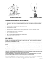
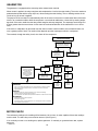
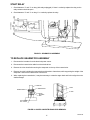
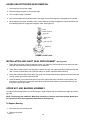
1
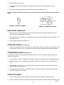
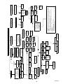
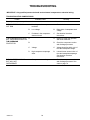
IMI CORNELIUS INC g One Cornelius Place g Anoka, MN 55303-6234
Telephone (800) 238-3600
Facsimile (800) 535-4231
Installation/Service Manual
UCR 700 SERIES CONTINUOUS-FLOW ICEMAKER
IMPORTANT:
TO THE INSTALLER.
It is the responsibility of
the Installer to ensure that
the water supply to the
dispensing equipment is
provided with protection
against backflow by an air
gap as defined in
ANSI/ASME A112.1.2-1979;
or an approved vacuum
breaker or other such
method as proved effective
by test.
Water pipe connections
and fixtures directly
connected to a potable
water supply shall be
sized, installed, and
maintained according to
Federal, State, and Local
Codes.
Part No. 630460154
May, 2001
Revision: November 6, 2009
Revision B
THIS DOCUMENT CONTAINS IMPORTANT INFORMATION
This Manual must be read and understood before installing or operating this equipment
© IMI CORNELIUS INC; 2001--2003
PRINTED IN U.S.A
TABLE OF CONTENTS
Page
SAFETY INFORMATION . . . . . . . . . . . . . . . . . . . . . . . . . . . . . . . . . . . . . . . . . . . . . . . . . . . .
1
RECOGNIZE SAFETY INFORMATION . . . . . . . . . . . . . . . . . . . . . . . . . . . . . . . . . . 1
UNDERSTAND SIGNAL WORDS . . . . . . . . . . . . . . . . . . . . . . . . . . . . . . . . . . . . . . . 1
FOLLOW SAFETY INSTRUCTIONS . . . . . . . . . . . . . . . . . . . . . . . . . . . . . . . . . . . . 1
GENERAL DESCRIPTION . . . . . . . . . . . . . . . . . . . . . . . . . . . . . . . . . . . . . . . . . . . . . . . . . .
3
TO THE USER OF THIS MANUAL . . . . . . . . . . . . . . . . . . . . . . . . . . . . . . . . . . . . . . .
DESCRIPTION . . . . . . . . . . . . . . . . . . . . . . . . . . . . . . . . . . . . . . . . . . . . . . . . . . . . . . . .
3
3
CLAIMS INSTRUCTIONS . . . . . . . . . . . . . . . . . . . . . . . . . . . . . . . . . . . . . . . . . . . . . .
WARRANTY REFERENCE INFORMATION . . . . . . . . . . . . . . . . . . . . . . . . . . . . . . .
DESIGN DATA . . . . . . . . . . . . . . . . . . . . . . . . . . . . . . . . . . . . . . . . . . . . . . . . . . . . . . . .
3
3
3
SPECIFICATION CHART . . . . . . . . . . . . . . . . . . . . . . . . . . . . . . . . . . . . . . . . . . . . . . .
INSTALLATION . . . . . . . . . . . . . . . . . . . . . . . . . . . . . . . . . . . . . . . . . . . . . . . . . . . . . . . . . . . .
4
7
PRE--INSTALLATION . . . . . . . . . . . . . . . . . . . . . . . . . . . . . . . . . . . . . . . . . . . . . . . . . . .
FREIGHT DAMAGE CLAIM . . . . . . . . . . . . . . . . . . . . . . . . . . . . . . . . . . . . . . . . . . . .
COUNTER . . . . . . . . . . . . . . . . . . . . . . . . . . . . . . . . . . . . . . . . . . . . . . . . . . . . . . . . . . .
ELECTRICAL . . . . . . . . . . . . . . . . . . . . . . . . . . . . . . . . . . . . . . . . . . . . . . . . . . . . . . . .
7
7
7
7
DRAIN . . . . . . . . . . . . . . . . . . . . . . . . . . . . . . . . . . . . . . . . . . . . . . . . . . . . . . . . . . . . . . 7
INSTALLATION . . . . . . . . . . . . . . . . . . . . . . . . . . . . . . . . . . . . . . . . . . . . . . . . . . . . . . . .
INITIAL START UP, CHECKS AND ADJUSTMENT INSTRUCTIONS . . . . . . . . .
GUIDE TO SERVICE . . . . . . . . . . . . . . . . . . . . . . . . . . . . . . . . . . . . . . . . . . . . . . . . . . . . . . .
8
8
11
ICEMAKER CLEANING AND SANITIZING PROCEDURES . . . . . . . . . . . . . . . . .
11
MAINTENANCE . . . . . . . . . . . . . . . . . . . . . . . . . . . . . . . . . . . . . . . . . . . . . . . . . . . . . . .
11
MONTHLY . . . . . . . . . . . . . . . . . . . . . . . . . . . . . . . . . . . . . . . . . . . . . . . . . . . . . . . . . . . 11
QUARTERLY . . . . . . . . . . . . . . . . . . . . . . . . . . . . . . . . . . . . . . . . . . . . . . . . . . . . . . . . 11
SEMI--ANNUALLY . . . . . . . . . . . . . . . . . . . . . . . . . . . . . . . . . . . . . . . . . . . . . . . . . . . . 12
WATER LEVEL CONTROL . . . . . . . . . . . . . . . . . . . . . . . . . . . . . . . . . . . . . . . . . . . . . .
12
HOW WATER LEVEL CONTROL WORKS . . . . . . . . . . . . . . . . . . . . . . . . . . . . . . . 12
PURPOSE . . . . . . . . . . . . . . . . . . . . . . . . . . . . . . . . . . . . . . . . . . . . . . . . . . . . . . . . . . . 12
TO REPLACE WATER LEVEL CONTROL . . . . . . . . . . . . . . . . . . . . . . . . . . . . . . . 13
TO REPLACE WATER LEVEL SAFETY SWITCH . . . . . . . . . . . . . . . . . . . . . . . . . 13
REFRIGERATION SYSTEM . . . . . . . . . . . . . . . . . . . . . . . . . . . . . . . . . . . . . . . . . . . . .
13
REFRIGERATION SYSTEM ADJUSTMENTS . . . . . . . . . . . . . . . . . . . . . . . . . . . . .
13
EXPANSION VALVE . . . . . . . . . . . . . . . . . . . . . . . . . . . . . . . . . . . . . . . . . . . . . . . . . . .
ADJUSTMENT AND TROUBLESHOOTING . . . . . . . . . . . . . . . . . . . . . . . . . . . . . . .
CONDENSER MODULATING VALVE . . . . . . . . . . . . . . . . . . . . . . . . . . . . . . . . . . . . .
CONDENSER MODULATING VALVE REMOVAL . . . . . . . . . . . . . . . . . . . . . . . . . .
BIN CONTROL . . . . . . . . . . . . . . . . . . . . . . . . . . . . . . . . . . . . . . . . . . . . . . . . . . . . . . . .
GEARMOTOR . . . . . . . . . . . . . . . . . . . . . . . . . . . . . . . . . . . . . . . . . . . . . . . . . . . . . . . . .
14
14
14
15
15
16
MOTOR CHECK . . . . . . . . . . . . . . . . . . . . . . . . . . . . . . . . . . . . . . . . . . . . . . . . . . . . . . .
START RELAY . . . . . . . . . . . . . . . . . . . . . . . . . . . . . . . . . . . . . . . . . . . . . . . . . . . . . . . .
TO REPLACE GEARMOTOR ASSEMBLY . . . . . . . . . . . . . . . . . . . . . . . . . . . . . . . .
AUGER AND EXTRUDING HEAD REMOVAL . . . . . . . . . . . . . . . . . . . . . . . . . . . . .
INSTALLATION AND SHAFT SEAL REPLACEMENT . . . . . . . . . . . . . . . . . . . . . .
16
17
17
18
18
i
630460127
TABLE OF CONTENTS (cont’d)
Page
UPPER NUT AND BEARING ASSEMBLY . . . . . . . . . . . . . . . . . . . . . . . . . . . . . . . . .
18
TO REPLACE BEARING . . . . . . . . . . . . . . . . . . . . . . . . . . . . . . . . . . . . . . . . . . . . . . 18
ELECTRICAL CHECKOUT . . . . . . . . . . . . . . . . . . . . . . . . . . . . . . . . . . . . . . . . . . . . . .
OVERLOAD CHECK . . . . . . . . . . . . . . . . . . . . . . . . . . . . . . . . . . . . . . . . . . . . . . . . . . .
COMPRESSOR CHECK . . . . . . . . . . . . . . . . . . . . . . . . . . . . . . . . . . . . . . . . . . . . . . . .
CAPACITOR CHECK . . . . . . . . . . . . . . . . . . . . . . . . . . . . . . . . . . . . . . . . . . . . . . . . . . .
19
19
19
19
SAFETY CONTROLS . . . . . . . . . . . . . . . . . . . . . . . . . . . . . . . . . . . . . . . . . . . . . . . . . .
TROUBLESHOOTING . . . . . . . . . . . . . . . . . . . . . . . . . . . . . . . . . . . . . . . . . . . . . . . . . . . . . .
20
24
THE COMPRESSOR WILL NOT RUN . . . . . . . . . . . . . . . . . . . . . . . . . . . . . . . . . . . .
THE COMPRESSOR STARTS BUT TRIPS REPEATEDLY ON THE
OVERLOAD PROTECTOR . . . . . . . . . . . . . . . . . . . . . . . . . . . . . . . . . . . . . . . . . . . . . .
THE COMPRESSOR RUNS BUT WILL NOT REFRIGERATE . . . . . . . . . . . . . . .
WARRANTY . . . . . . . . . . . . . . . . . . . . . . . . . . . . . . . . . . . . . . . . . . . . . . . . . . . . . . . . . . . . . .
24
24
24
30
LIST OF FIGURES
FIGURE 1. CLEARANCE REQUIREMENTS . . . . . . . . . . . . . . . . . . . . . . . . . . . . . . .
FIGURE 2. ICEMAKER FLOAT ASSEMBLY . . . . . . . . . . . . . . . . . . . . . . . . . . . . . . .
FIGURE 3. UPPER NUT AND BEARING ASSEMBLY . . . . . . . . . . . . . . . . . . . . . .
5
9
12
FIGURE 4. EXPANSION VALVE . . . . . . . . . . . . . . . . . . . . . . . . . . . . . . . . . . . . . . . . .
FIGURE 5. ADJUSTMENT SCREW . . . . . . . . . . . . . . . . . . . . . . . . . . . . . . . . . . . . . .
FIGURE 6. GEARMOTOR ASSEMBLY . . . . . . . . . . . . . . . . . . . . . . . . . . . . . . . . . . .
FIGURE 7. AUGER AND EXTRUDING HEAD REMOVAL . . . . . . . . . . . . . . . . . .
FIGURE 8. SHAFT SEAL . . . . . . . . . . . . . . . . . . . . . . . . . . . . . . . . . . . . . . . . . . . . . . .
FIGURE 9. OVERLOAD CHECK . . . . . . . . . . . . . . . . . . . . . . . . . . . . . . . . . . . . . . . .
15
15
17
17
18
19
FIGURE 10. COMPRESSOR CHECK . . . . . . . . . . . . . . . . . . . . . . . . . . . . . . . . . . . .
FIGURE 11. GEAR MOTOR OVERLOAD . . . . . . . . . . . . . . . . . . . . . . . . . . . . . . . . .
FIGURE 12. WIRING DIAGRAM . . . . . . . . . . . . . . . . . . . . . . . . . . . . . . . . . . . . . . . . .
FIGURE 14. PANEL COMPONENTS . . . . . . . . . . . . . . . . . . . . . . . . . . . . . . . . . . . . .
FIGURE 15. ICE CHUTE COMPONENTS . . . . . . . . . . . . . . . . . . . . . . . . . . . . . . . . .
FIGURE 16. WATER LEVEL CONTROL COMPONENTS . . . . . . . . . . . . . . . . . . .
FIGURE 17. ELECTRICAL BOX COMPONENTS . . . . . . . . . . . . . . . . . . . . . . . . . .
19
20
22
26
27
27
27
FIGURE 18. COMPRESSOR COMPONENTS . . . . . . . . . . . . . . . . . . . . . . . . . . . . .
FIGURE 19. FRONT END COMPONENTS . . . . . . . . . . . . . . . . . . . . . . . . . . . . . . . .
28
28
FIGURE 20. CONDENSER MOTOR COMPONENTS . . . . . . . . . . . . . . . . . . . . . . .
FIGURE 21. EVAPORATOR COMPONENTS . . . . . . . . . . . . . . . . . . . . . . . . . . . . . .
FIGURE 22. CONDENSER COMPONENTS . . . . . . . . . . . . . . . . . . . . . . . . . . . . . . .
FIGURE 23. BASE COMPONENTS . . . . . . . . . . . . . . . . . . . . . . . . . . . . . . . . . . . . . .
28
29
29
29
FIGURE 24. WHEEL COMPONENTS . . . . . . . . . . . . . . . . . . . . . . . . . . . . . . . . . . . .
29
LIST OF TABLES
TABLE 1. DESIGN DATA . . . . . . . . . . . . . . . . . . . . . . . . . . . . . . . . . . . . . . . . . . . . . . .
630460127
ii
3
SAFETY INFORMATION
Recognize Safety Information
This is the safety-alert symbol. When you see this
symbol on our machine or in this manual, be alert to
the potentially of personal injury.
Follow recommended precautions and safe operating
practices.
Understand Signal Words
A signal word - DANGER, WARNING, OR CAUTION
is used with the safety-alert symbol. DANGER identifies the most serious hazards.
Safety signs with signal word DANGER or WARNING
are typically near specific hazards.
General precautions are listed on CAUTION safety
signs. CAUTION also calls attention to safety messages in this manual.
DANGER
WARNING
CAUTION
Follow Safety Instructions
Carefully read all safety messages in this manual and on your machine safety signs. Keep safety signs in
good condition. Replace missing or damaged safety signs. Learn how to operate the machine and how to
use the controls properly. Do not let anyone operate the machine without instructions. Keep your machine in
proper working condition. Unauthorized modifications to the machine may impair function and/or safety and
affect the machine life.
CAUTION: Very high discharges pressure is present in the system. Quick disconnects on
your gages will minimize danger and loss of refrigerant.
CAUTION: The Unit requires a separate electrical line. See Instruction Manual for proper
fuse size.
WARNING: There must be adequate clearance around the Icemaker. Allow 25--inches on the
front side for service access, 4--inches on side opposite the storage bin, and 4--inches on
the back side for air exaust.
NOTE: The Unit must be installed per local plumbing and electrical codes. Failure to do so may cause
damage to the Unit which would void the factory warranty.
NOTE: Using parts other thean genuine factory manufactured parts relieves the manufacturer of all
liability. The manufacturer reserves the right to change specifications at any time.
1
6630460154
THIS PAGE LEFT BLANK INTENTIONALLY
630460154
2
GENERAL DESCRIPTION
TO THE USER OF THIS MANUAL
This manual covers the installation and assembly of the Air--Cooled or Water--Cooled Model UC700 Icemaker
with the Model UC150 Dispenser. Refer to Table of Contents for page location of detailed information pertaining
to questions that may arise during installation or operation of this equipment.
DESCRIPTION
The UC700 is a chuncklet Icemaker designed to be installed under a counter adjacent to an Ice Dispenser or an
Ice Storage Bin. The Icemaker will deliver ice to either the left or right side. The Icemaker requires a 12--inch by
12--inch opening at the lower front of the Unit for air intake. A minimum of 1.5 sq. ft. opening must be provided
out the left or right side and the rear of the machine for air exaust.
CLAIMS INSTRUCTIONS
Claims: In the event of shortage, notify the carrier as well as IMI Cornelius immediately. In the event of damage, notify the carrier. IMI Cornelius is not responsible for damage occurring in transit, but will gladly
render assistance necessary to pursue your claim. Merchandise must be inspected for concealed damage within 15 days of receipt.
WARRANTY REFERENCE INFORMATION
Warranty Registration Date
(to be filled out by customer)
Unit Part Number:
Serial Number:
Install Date:
Local Authorized
Service Center:
DESIGN DATA
Table 1. Design Data
Unit Model Number:
UCR700--A Series Continuous--Flow Icemaker (Air--Cooled)
UCR700--W Series Continuous--Flow Icemaker (Water--Cooled)
Unit Overall Dimensions:
Height
Width
Depth
27 inches
15.7 inches
25.5 inches
Clearances Dimensions Required:
Front Side Service Access (Removable front panel to allow removal of
Unit)
Side Opposite Storage Bin for Air Exaust
Rear for Air Exaust
Weights:
Shipping Weight
25 inches
4 inches
4 inches
184 pounds
3
630460154
Table 1. Design Data (cont’d)
Water Supply--Water inlet fitting is 1/4--inch SAE flare located at the top front of the Unit. The Unit is designed
to
operate on water pressure between 10 PSI and 90 PSI.
Drain Overflow Line (Located at rear of the Unit)
3/8--inch Flexible Tubing
Ambient Operating Temperature
40° F to 100° F
Electrical:
Unit Electrical Rating
115 VAC, 60 Hz, 15.6 Amps,
Single Phase
115 VAC, 60 hz, 20 Amps
Dedicated 3--Wire
Grounded Circuit
Recommended Electrical Supply
SPECIFICATION CHART
Models
Condensing
g
U i
Unit
VAC
HZ
PH
Wire
Comp.
p
RLA
Fan
Amps
A
GRMTR
A
Amps
UCR700--A
UCR700--W
Air Cooled
Water Cooled
115
115
60
60
1
1
2
2
12
12
1.6
N/A
2
2
UC700
Capacity Lbs./24 hr.
600
550
500
450
400
350
90
80
70
60
50
Water Temperature Deg. F
- 50
- 70
- 90
- 100
Air Temperature Deg. F
630460154
4
Capacity Lbs./24 hr.
650
Refrigerant
Oz.
Type
24
R404A
13
R404A
Circuit
F
Fuse
20
20
FIGURE 1. CLEARANCE REQUIREMENTS
5
630460154
THIS PAGE LEFT BLANK INTENTIONALLY
630460154
6
INSTALLATION
PRE--INSTALLATION
Freight Damage Claim
The delivery of your equipment (Frieght Company, Distributor, or dealer) is responsible for loss or damage of
your shipment. All claims must be filed with the deliverer of your equipment. Please follow the steps below to
determine if your shipment is satisfactory or if a claim must be filed:
1. Check the number of products delivered against the number of products listed on the delivery receipt.
Should the totals not match, have the driver note all errors on both copies and both you and the driver sign
and date said notation.
2. Inspect all cartons for visible damage. Open and inspect as required before the driver leaves and have him
or her note any damage on the receipts. All damaged claims must be inspected within 15 days of delivery.
Notify your carrier immediately if concealed damage is found after delivery.
3. Should concealed damage be found when the product is unpacked, retain the packing material and the
product and request an inspection from the deliverer.
4. All claims for loss or damage should be filed at once. Delays in filing will reduce the chance of achieving a
satisfactory resolution to the claim.
Counter
1. A flat and level counter space sufficiently strong to support the weight of the Dispenser and the Icemaker.
The Icemaker may be installed on the left or the right side of the Dispenser.
2. General Requirements:
A.
The front of the Icemaker must be free of obstructions.
B.
Allow a 4--inch minimum clearance between exaust side of the Icemaker and adjacent equipment.
C.
A louvered front panel (12--inches X 12--inches) aligned with the air inlet of the Icemaker and adequate ventilation (1.5 Sq. feet opening) in the counter for exaust air.
D.
A removable panel in the counter face (from 2--inches below the top of the counter to the floor, a minimum of 19--inches wide) to allow removal of the Icemaker.
Electrical
Two separate 20 amp, 120VAC, 60 Hz electrical circuits.
Drain
One drain beneath the counter at floor level which will accomodate both the drain from the Icemaker and the
Dispenser.
7
630460154
INSTALLATION
1. Keep unit in the upright position, remove carton and pallet from the Icemaker and inspect for damage. If
any damage is found, file a claim with carrier immediately.
2. Locate startup card either on outside of container or on plastic liner. Fill in proper information and send one
to factory, and other copy to distributor. Postage is prepaid.
3. Install the Dispenser first, following installation instructions supplied with the Dispenser.
4. Remove the two hole plugs from the side of the dispenser.
A.
The plugs are pressed in and sealed with a silastic sealant. To remove pry the outside cap off and
then press the inside plug into the bin. Discard both plugs.
B.
Install the icemaker alignment brackets (Supplied with icemaker) to the dispenser (See Figure 2).
5. Install the Icemaker:
A.
Install the icemaker alignment brackets (Supplied with icemaker) to the icemaker (See Figure 2).
B.
Roll the Icemaker into the cabinet alongside the Dispenser.
C.
Level and align the icemaker to the dispenser using the four level adjustment bolts located on the lower front of the Icemaker.
D.
Install the locking bolt on the lower front of the icemaker.
E.
Connect drain, power and water.
6. Install transport tube:
A.
Insert the ice transport tube through the bin into the transport elbow on the Icemaker. (Note: The icemaker is equipped with a safety switch located at the base of the elbow, this switch will prevent the
icemaker from running if the elbow is not properly installed).
B.
Align the nylon lock screw on the elbow with the recess on the tube. Install lock screw.
7. Connect bin thermostat:
A.
Locate bin thermostat cable supplied with the icemaker (Black cable) and connect to electrical box on
the UCR700 and the receptacle on the side of the dispenser.
630460154
FIGURE 2. SIDE BRACKET INSTALLATION
8
INITIAL START UP, CHECKS AND ADJUSTMENT INSTRUCTIONS
NOTE:
Do not start Icemaker before completing installation steps on pages 7 and 9.
Turn on water supply (if Icemaker is water cooled turn water on to condenser also) turn on main power switch
(located on top of electrical box), and make the following system checks:
NOTE: If Icemaker will not start be sure water reservoir is full. Low water safety control must be properly adjusted to start and shut down the Icemaker. If water level drops below bottom of reservoir, the
Icemaker must shut down. Adjustment is made by moving magnet up or down.
Water Level—If necessary adjust float by bending float arm up or down as needed, push float assembly down
until Icemaker stops running. Release float and Icemaker will restart. Keep water in reservoir at level line while
the Icemaker is in operation. See Figure 3
Low Water Safety Control—Adjust magnet by bending magnet arm as needed to shut unit down if water level
drops below bottom of reservoir.
Bin Control—Place ice around probe, unit should shut down in one minute. Remove ice from around probe,
unit should start in two minutes.
NOTE: For altitudes over 1000 feet above sea level, adjust range screw (behind end cover). Half turn
max. raises setting 4_F approx.
FIGURE 3. ICEMAKER FLOAT ASSEMBLY
Water modulating valve (water cooled units only)—Opening point of condenser water modulating valve
should be set to maintain proper operating pressure in the refrigeration system high side. (see chart on
page 13). Closing point of valve should be set low enough to close valve during compressor stand by periods.
To raise, turn counterclockwise, to lower turn clockwise.
9
630460154
THIS PAGE LEFT BLANK INTENTIONALLY
630460154
10
GUIDE TO SERVICE
WARNING: Disconnect electrical power to the Icemaker to prevent personal injury before
attempting any internal maintenance. Only qualified personnel should service internal
components or electrical wiring.
ICEMAKER CLEANING AND SANITIZING PROCEDURES
Do not use any of the ice made during cleaning operations.
Clean and sanitize ice storage area when cleaning icemaker.
1. Turn machine off.
2. Shut off water supply.
3. Remove ice from storage bin.
4. Mix approved cleaner (2 gallons as directed). Recommended cleaner: Calgon Corp. of Virginia Chemicals, ice machine cleaner. Mixture: 3-1/3 ounces per gallon of water.
5. Clean auger assembly and ice transition tube in a sink using cleaner mixture and reinstall in icemaker.
6. Turn machine on and add cleaner solution to water level control until 2 gallons have been used.
7. Turn on water supply and run machine for 15 minutes.
8. Turn off machine and remove all ice.
9. Sanitize using household liquid bleach (50 ppm chlorine). Mixture: 1 fluid ounce per gallon room temperature water. 2 minute exposure time.
10. Sanitize auger assembly and ice transition tube in a sink using sanitizing solution and reinstall in icemaker.
11. Fill icemaker with sanitizer by slowly pouring solution into water feed reservoir until full. Solution will drain
through overflow tube. Do not run machine. Allow to air dry.
12. If icemaker is used in conjunction with ice dispenser or storage bin, follow manufacturer’s recommended
cleaning instructions at this time.
MAINTENANCE
Preventive maintenance can increase the trouble free life of your icemaker. Many authorized service agencies
offer service contracts for your icemaker. Contact your local distributor for further information.
Monthly
1. Clean the condenser. Use a brush, vacuum cleaner or blow from inside with air or CO2 gas.
2. Inspect water feed reservoir at lease once a month until a definite pattern for cleaning and sanitizing has
been established.
Quarterly
This is the maximum period of time between cleaning and sanitizing the icemaker. In addition to recommended
monthly procedure, and if a more frequent cleaning and sanitizing pattern has not been established, unit must
be cleaned and sanitized.
11
630460154
Semi-- Annually
Semi-Annually in addition to all previously established service procedures perform the following:
1. Check for water leaks in tube connections, water fittings and lower Icemaker water seal.
2. Check drain tubes for clogs and aged tubes. Replace if tubes are stained or brittle.
3. Check for signs of condensation. Clean where necessary and replace insulation properly.
4. Check safety circuits for proper operation.
5. Check refrigeration system (see page 13).
6. Check unit for abnormal noise. Tighten machine and cabinet screws, if necessary.
7. Check white upper bearings on auger assembly. If bearings are less than 1/16″ thick, replace. See Figure 4
REPLACE
OK
1/16″
1/16″
OK
REPLACE
FIGURE 4. UPPER NUT AND BEARING ASSEMBLY
WATER LEVEL CONTROL
How Water Level Control Works
When water is introduced through the inlet fitting the float rises. the float pushes against a lever which in turn
forces the poppet assembly against the inlet fitting valve seat which seals the water off. See Figure 3 Before the
water inlet is sealed the safety switch is operated. In the event of a water failure the float would drop down and
operate the safety switch to shut off the machine.
If water level control will not shut off and seal at level as indicated, be sure inlet pressure does not exceed recommended factory operating range.
Under ordinary circumstances adjustment should not be necessary providing it was properly adjusted when unit
was installed or relocated. If, however, the control becomes inoperative, repair or replace. See Start-Up Adjustment, page 9.
Purpose
1. To automatically maintain proper water level in the evaporator when unit is running and making ice.
2. A safety switch is operated in the event of an interruption in water supply. The switch shuts off the electrical
power to the icemaker and its refrigeration system. Switch will reset as soon as cause of water failure has
been corrected and proper water level in icemaker has again been reached.
630460154
12
3. The transparent bowl not only provides a visible check of water level, but also is a good guide to the internal conditions which exist within the icemaker assembly itself. (See Cleaning Procedure.)
To Replace Water Level Control
1. Shut off the water supply. Shut off the main power switch or unplug the ice dispenser from electrical outlet.
2. Remove the flexible tubing from bottom of water level control and drain water from water level control and
evaporator.
3. Remove flexible tubing at bottom of water level bowl connected to the overflow.
4. Hold water inlet fitting with proper tool to prevent it from rotating when disconnecting the water inlet.
5. Remove wing nut holding water control to its mounting bracket. Control can be removed by lifting straight
up.
To Replace Water Level Safety Switch
1. Shut off main power switch or unplug the ice dispenser from electrical outlet.
2. Unplug molex connector connecting switch to electrical box.
3. Remove the 2 screws anchoring the water level safety switch to the bottom of the water level control
mounting bracket.
REFRIGERATION SYSTEM
NOTE: Thermostatic Expansion Valve No Adjustment
±10 Lbs Discharge Pressure
WATER TEMPERATURE
A
40°
65°
90°
I
50°
174
177
180
R
60°
202
205
208
70°
230
233
236
T
80°
265
269
272
E
90°
300
304
307
M
100°
328
334
340
P
REFRIGERATION SYSTEM ADJUSTMENTS
A complete understanding of the icemaker and hermetic refrigeration system is necessary before any adjustments are made. The refrigeration technician must use high and low side pressure readings, water and air temperatures, plus general conditions of cleanliness to assess the refrigeration system status when making any
adjustments.
All icemaker products are tested and adjusted at the factory prior to shipment where the ambient temperature
ranges from 65_ to 90_F, depending on the season of the year.
Whenever a new icemaker product is initially installed and started-up, it is imperative that the start-up operation
make the following checks and/or readjustments for local conditions.
13
630460154
EXPANSION VALVE
You will find a thermostatic expansion valve on icemakers, which is used to control the amount of refrigerant
flowing through the evaporator. Improperly installed or defective expansion valves may cause low production,
soft ice, squeaking from evaporator and excessive load inside evaporator.
By using general refrigeration system troubleshooting along with the pressure charts you can easily determine
whether or not the expansion valve is working properly.
ADJUSTMENT AND TROUBLESHOOTING
When troubleshooting the expansion valve you must first be sure you have adequate water flowing into evaporator, a clean condenser, unit is properly ventilated, and system is properly charged and free from any restrictions. Also be sure compressor is operating properly.
Second, take reservoir water temperature and air temperature from condenser inlet and determine at what pressure unit should be running. Machines are equipped with thermostatic valves, there is NO adjustment. If correct
pressure cannot be obtained, first be sure system has time to stabilize 10-15 minutes. Second, be sure sensing
bulb is located at 12:00 position on outlet side of evaporator about 3-4 inches away from evaporator and be sure
to insulate well and clamp tightly to tubing. If system pressures are still not adequate, take a second water and
air temperature reading and go over other parts of system for possible problems. If proper charge is questionable evacuate and recharge to nameplate and leak check. If valve still malfunctions replace valve.
When replacing valve be sure to bleed refrigerant gas from low side port so as not to lose refrigerant oil. Use
general refrigerant system practices when replacing and recharging unit. After new valve is in place, go through
previous monitored adjustments and troubleshooting to be sure valve is functioning properly.
NOTE: Units with thermostatic expansion valve—The valve is located on bottom refrigerant line. Sensing bulb is located on top refrigerant line. On water cooled units adjust condenser modulating valve
before troubleshooting expansion valve.
CAUTION: Very high discharge pressure is present in system. Quick disconnects on your
gauges will minimize danger and loss of refrigerant. Comply with federal regulations for
reclaiming refrigerant.
CONDENSER MODULATING VALVE
The reason for using a water modulating valve is to supply the correct amount of water to the condenser. and to
maintain a proper operating pressure to refrigeration system high side.
The flow of water through the valve is increased as the high side pressure rises and is decreased as high side
pressure lowers.
To calibrate the amount of water flow with the refrigeration system high side pressure, turn adjustment screw
located on end of valve opposite of bellows. See Figure 6. Turn screw counterclockwise to raise opening point
or clockwise to lower opening point. Opening point of valve should be set to maintain proper operating pressure
in refrigeration system high side. Refer to Pressure Chart on page 3. Closing point of valve should be set low
enough to close valve during compressor stand-by periods.
NOTE: Cold water will absorb heat faster than warm water. The water flow will therefore automatically
increase as inlet temperature increases.
630460154
14
SIGHT
GLASS
THERMOSTATIC
EXPANSION VALVE
FIGURE 5. EXPANSION VALVE
FIGURE 6. ADJUSTMENT SCREW
CONDENSER MODULATING VALVE REMOVAL
1. Disconnect power to unit, then shut off water supply to condenser and evacuate refrigerant from system.
2. Remove inlet water line from Condenser Modulating Valve. Also remove tube from high side refrigerant
line.
3. Remove Condenser Modulating Valve and bracket from unit.
4. Remove valve from bracket.
5. Replace Condenser Modulating Valve by reversing Steps 2 thru 4. Then pull system into vacuum.
6. Charge unit with proper amount of refrigeration.
7. Turn power and water on to unit.
8. With unit running, adjust modulating valve to proper setting.
9. Go through a complete system check.
BIN CONTROL
The type of bin control used on all UC Models is thermostatically controlled. The switch itself is inside the electrical box of the Dispenser and can be serviced from the front of the unit. The cap tube bulb is located in the
thermostat well directly under the ice inlet.
To test switch, disconnect power to unit and remove one wire from switch. Connect both leads of your ohmmeter to the Bin Control Switch terminals. With control bulb at room temperature ohmmeter should read “Closed
Circuit”.
Now cover the control bulb with ice, within 1 minute switch should “click” and ohmmeter should read “Open Circuit.” The Bin control is in electrical series with a 24 volt transformer located in the ice dispenser and a 24 volt
control relay located in the Icemaker.
The Bin 24 volt control relay is in electrical series with coil on antifreeze relay along with the low water safety. If
unit is water cooled, the condenser high pressure cut out is also in series.
The Control Switch is held in place inside electrical box by 2 screws. Control bulb is positioned under ice chute
and can be replaced by removing the capillary from the thermostat well.
The most important thing to remember when replacing probe is to be careful not to cut or kink probe and be
sure sensor bulb is located in a position to shut unit down before ice reaches ice chute.
This icemaker is equipped with a safety ice level sensor. This sensor control is located on top of theevaporator.
This switch is also in electrical series with the anti-freeze relay and other safety circuitry.
15
630460154
GEARMOTOR
The gearmotor is equipped with a start relay and a manual reset overload.
When current is applied, the relay energizes and completes the circuit to the start winding. The motor reaches a
predetermined speed and the relay drops out, disconnecting the start winding. The run winding remains in the
circuit as long as current is applied.
The purpose of the overload is to automatically shut off the motor in the event of a mechanical bind of the transmission, an overload condition within the evaporator or an electrical malfunction. It does this by sensing amperage draw. If the motor stalls the start relay would energize and stay energized. The amperage would surge 5 to
6 times greater than the normal draw. In this event the overload would shut off the transmission in 4 to 8 seconds.
If the motor is subjected to an abnormal load, but does not reach a stall condition, the overload will react, but
over a greater period of time. The reaction time depends upon the amperage to which it is subjected.
The overload, through the safety circuit, also shuts off the compressor.
GEARMOTOR
OVERLOAD TRIPPED
Check water level control
and evaporator water tube
for line build-up restrictions.
NO
YES
CAUTION
Clear ice from
evaporator and
auger before
resetting overload.
CLEAN
See Instructions.
Reset overload.
IMPORTANT
Icemaker runs when
reset but problem has
not been found.
Continue checking for
overload as follows to
guard against future
problems.
Icemaker
runs.
Short run. Trips
again in 2
minutes. Check
gearmotor circuits.
OVERLOAD GUIDE
ELECTRICAL:
S
S
S
High or low voltage. Weak power lines can cause overloads on icemakers restarts.
High running current (2.4amps or above). Check motor circuits and start relay.
Auger delay failed.
Resets but
motor does
not run.
Resets but
motor does
not run.
Check
gearmotor
circuits.
Will not
Reset.
Overload
hot try
again.
Will not
reset.
Replace
overload.
ICEMAKER
S
S
S
Mechanical parts worn. Scored evaporator or auger. Worn thrust bearing.
Icemaker not turning off. Failed ice level control.
Over compression. Low water inlet temperature. Restrictions in water line from reservoir.
REFRIGERANT
S
S
S
Contaminated charge or bad compressor.
Low charge or gas leak.
Low suction pressure. Improper expansion valve. Sensing bulb location or insulation
and/or defective expansion valve.
MOTOR CHECK
The resistance readings on the winding will be between 5 to 25 ohms. A meter capable of these low readings
must be used. The start relay cover must be removed. (See Figure 7).
If no continuity on start or run winding test, replace gearmotor. If continuity on grounded motor test, replace
gearmotor.
630460154
16
START RELAY
1. Check between “2” and “4” on relay (with relay unplugged). If there is continuity replace the relay, as the
relay contacts should be open.
2. Check between “3” and “4” on relay, if no continuity replace the relay.
FIGURE 7. GEARMOTOR ASSEMBLY
TO REPLACE GEARMOTOR ASSEMBLY
1. Disconnect the icemaker from the electrical power source.
2. Disconnect the transmission cable from the electrical box.
3. Remove the 4 hex head bolts securing the evaporator to the top of the transmission.
4. Remove the 4 bolt’s holding the transmission and bracket to frame base, while supporting the weight of the
evaporator. Remove the transmission from the unit.
5. When replacing the transmission, it may be necessary to rotate the auger back and forth to align the motor
shaft and auger.
AUGER NUT
AUGER
BEARING NYLON
BEARING DELRIN
“D” DRIVE
GROOVE
EXTRUDING
HEAD
ANTI-- ROTATION
RIB - 3 PLACES
FIGURE 8. AUGER AND EXTRUDING HEAD REMOVAL
17
630460154
AUGER AND EXTRUDING HEAD REMOVAL
1. Disconnect unit from power supply.
2. Remove storage container cover and put aside.
3. Turn off water supply to icemaker.
4. After ice has melted from head take hold of the auger nut and lift straight up to disengage from icemaker.
5. When replacing the auger assembly, make certain that both the auger engages the output shaft drive and
the extruding head ribs engage the evaporator tube. (See Figures 8 )
E-- RING
WASHER, PLAIN FLAT
SHAFT SEAL
MOUNT, SHAFT
SEAL
SEAT, SHAFT SEAL
GEARMOTOR
FIGURE 9. SHAFT SEAL
INSTALLATION AND SHAFT SEAL REPLACEMENT
(See Figure 9)
1. Place shaft seal locator seat and shaft seal mount over gearmotor output shaft and push down until shaft
seal seat and shaft seal mount rest flush on top of gearmotor.
2. Place rubber coated ceramic seal (important: ceramic face up) over output shaft and push down until seal
nest in recess of shaft seal mount. (lubricate rubber on ceramic seal with rubber lubricant).
3. Place shaft seal with carbon face down (spring up) over output shaft and push (gently) downward until seal
rests on carbon face of the output shaft seal.
4. Place flat washer over output shaft and let rest on the output shaft seal. Push down on the washer compressing the spring on the output shaft seal. While holding the seals (down) in place slide the E-ring into
the groove on the output shaft.
UPPER NUT AND BEARING ASSEMBLY
The upper white bearing located on top of the auger is used to absorb the force between the auger and extruding head.
NOTE: The bearings are 3/32″ thick. When they wear below 1/16″ they should be replaced. Bearings to
be inspected for wear during quarterly maintenance. (See Figure 4)
To Replace Bearing
1. Disconnect unit from electric power.
2. Remove top panels.
630460154
18
3. Remove Dispense Tray Cover.
4. Use an open end wrench on auger nut connected to bearing and turn counterclockwise to remove
assembly.
5. Remove worn bearings. Replace with new bearings and then reinstall assembly.
NOTE: If auger turns with nut, remove cover on top of gearmotor stator and hold motor while loosening nut.
FIGURE 10. OVERLOAD CHECK
FIGURE 11. COMPRESSOR CHECK
ELECTRICAL CHECKOUT
1. Be sure the unit is disconnected from the power source. Remove the compressor electrical box cover.
Check for obvious damage and loose wires.
2. Disconnect the fan motor leads. Since capacitors store energy, short the capacitor with a screwdriver. This
will prevent shocks.
3. Disconnect the compressor terminal wires.
OVERLOAD CHECK (See Figure 10)
1. Using a volt-ohmmeter check the continuity across the overload, contact #1 and #3. If none, wait for unit to
cool down and try again. If still no continuity, the overload protector is defective and should be replaced.
COMPRESSOR CHECK (See Figure 11)
The resistance readings on the windings will be between 0.25 to 10.00 ohms, a meter capable of these low
readings must be used.
1. Check between “C” and “R.” Replace the compressor if there is no continuity as the run windings are open.
2. Check between “C” and “S.” Replace the compressor if there is no continuity as the start windings are
open.
3. Check between “C” and “R” or “S” and the shell of the compressor. If there is continuity, replace the compressor as the motor is grounded.
4. Check between screw terminal on the overload and “C” on the compressor. Check and repair the lead or
connections if there is no continuity.
CAPACITOR CHECK
1. Check or replace start capacitor, disconnect bleed resistor before checking for shorted capacitor.
2. Check or replace run capacitor (if supplied) check for shorted capacitor or either terminal grounded to case.
19
630460154
FIGURE 12. GEAR MOTOR OVERLOAD
SAFETY CONTROLS
Your icemaker unit has several safety and control devices incorporated into its design.
WARNING: None of the below described devices should ever be “bypassed” to allow the
unit to function.
The safety and control system shut-off devices are:
1. Low water shut off reed switch located in icemaker float assembly. (Automatic reset type.)
See Figure 3
2. Gearmotor thermal overload, manual reset type (red button on motor). See Wiring Diagram Figure 13.
3. Compressor thermal overload, automatic reset type. See Figure 10
4. Anti-freeze relay and associated circuit. See Wiring Diagram Figure 13.
5. Main service switch located on top of the control box. See Wiring diagram Figure 13.
6. Bin Control.
7. High pressure cut out (water cooled only).
630460154
20
GUIDE TO GOOD ICE
CUSTOMER
COMMENTS
CHECK ICEMAKER
LOCATION CONDITIONS
FIRST
“It runs but the ice is
too soft.”
S Proper air flow for condensing system.
“The icemaker is not
producing enough ice.”
S Location too close to high
units such as coffee urns,
deep fryers, grills, etc.
“The ice is too wet.”
S Supply water conditions
Water too warm
(above 90_F).
Water artificially softened
above 262 ppm sodium chloride.
Normal water supply too high
in total dissolved solids
(above 500 PPM).
“It makes too much
noise.”
(With this comment
the ice is usually
extremely hard and
larger than normal.)
S Check to see if noise
objection is normal fan and
air flow noise.
Over
Compression
S Supply water conditions.
Water too cold (below
50_F). (Possibly running
from pre-cooler.)
CHECK ICE MAKER
S Use gauges for checking
suction and head
pressures. See manual
for correct reading and
conditions. Check frost
line and sight glass.
S Check water level for
proper adjustment and
restrictions. See
Manual.
S Check evaporator
assembly for worn
parts, bearings, scored
evaporator and auger,
bad expansion valve.
etc.
S Check for loose parts
and screws rattling.
S Check evaporator
assembly for worn
parts, bearings, scored
evaporator and auger,
bad expansion valve,
etc.
S Obstructions partially
blocking ice exit from top of
evaporator.
S Check fan and fan shroud.
21
630460154
630460154
22
FIGURE 13. WIRING DIAGRAM
23
630460154
Open
valve
Evacuate and
recharge system.
Clean condenser.
Non-condensible
in system.
Condenser
fan not
running.
LAC not operating
properly (minimum
discharge pressure
180 lbs.).
Check for
leaks.
Replace LAC valve,
evacuate and
recharge system.
Remote condenser
units only
ICEMAKER RUNS BUT
DOES NOT MAKE ICE
Replace
dryer.
Evacuate
and
recharge
system.
Plugged
liquid line
dryer.
Replace
valve.
Evacuate
and
recharge
system.
Check gears in
gearbox.
No
Check if
auger is
turning.
Icemaker
froze up.
Clean
and
tighten.
Replace
valve.
Plugged or
faulty TXV.
Bulb
loose.
Valve
stuck
open.
TXV not
operating
properly.
IMPORTANT
Icemaker runs when reset
but problem has not been
found.
Continue checking for
overload as follows to
guard against future
problems
Clean all related
drain lines.
Yes
No
Short run trips
again in 2 minutes. Check gearmotor circuit.
Icemaker runs
Refer to guide
to Good Ice in
service manual.
Check bin switch
ICEMAKER OPERATING BUT
SOFT ICE
Check
gearmotor
circuit.
Reset but
motor does
not run.
Reset
overload.
CAUTION
Clear ice from
evaporator and
auger before resetting overload.
No
Will not
reset
replace
overload
Overload
hot try
again.
Will not
reset.
CLEAN
see
instructions.
Yes
Check water level control
and evaporator water tube
for lime build up restriction.
GEARMOTOR OVERLOAD
TRIPPED
OVERLOAD GUIDE
ELECTRICAL
High or low voltage weak power lines can cause overloads on icemaker restarts
High running current. Check motor circuits and start relay -- Auger delay failed.
ICEMAKER
Mechanical parts worn. Scored evaporator or auger. Worn thrust bearing.
Ice maker not turning off. Failed ice level control.
Over compression. Low water inlet temperature. Restriction in water line from
reservoir.
REFRIGERANT
Contaminated charge or bad compressor.
Low charge or gas leak.
Low suction pressure. Improper expansion valve sensing bulb. Location or insulation
and/or defective expansion valve
Replace valve
evacuate and
recharge.
TXV bulb
lost charge.
Check if extruding
head is down in
evaporator tube.
Clean and
insulate.
Bulb
uninsulated.
Suction line
not
insulated.
Low suction pressure
(20 lbs. or below).
Check that water is turned on.
Check for restriction in water line.
Check incoming water pressure
(minimum 10 lbs.).
Check water safety switch.
LOW WATER SAFETY
SWITCH OPEN
High suction pressure
(30 lbs. or above).
Check drive on
gearmotor.
Check for
kinks or
damage to
liquid line.
Restricted
liquid line.
Condenser
dirty or
restricted.
Head
Pressure
high.
Evaporator water tube
may have an air bubble.
Clear air bubble from
tube.
Check line voltage.
Check compressor winding
& components.
Condenser fan running
but compressor not running
Check electrical circuit
to fan motor.
Check fan motor.
Low on
refrigerant.
Too much
refrigerant in
system.
Check power
to condenser.
Remote condenser
not running.
Remote condenser
units only
Check electrical
wiring in control box
for loose connections.
Low pressure switch open
or cycling on and off.
Discharge
king valve
partially
closed.
High pressure
switch open or
cycling on and off.
Check electrical wiring in control box for loose connections.
Check for failed service
switch or relay.
Check power to machine.
NO POWER
TROUBLESHOOTING CHART - ICEMAKER NOT OPERATING
TROUBLESHOOTING
IMPORTANT: Only qualified personnel should service internal components or electrical wiring.
TROUBLESHOOTING COMPRESSORS
Trouble
Probable Cause
Remedy
Basically the compressor problems can be narrowed down to three areas of checkout.
THE COMPRESSOR WILL
NOT RUN
THE COMPRESSOR STARTS
BUT TRIPS REPEATEDLY ON
THE OVERLOAD
PROTECTOR
THE COMPRESSOR RUNS
BUT WILL NOT
REFRIGERATE
630460154
A.
No voltage to the compressor
terminals.
A.
Check circuit.
B.
Low voltage.
B.
Below 90% of nameplate rated
voltage.
C.
Problems in the compressor
electrical circuit.
C.
See electrical checkout
instructions.
A.
A.
Check for proper fan operation
and clean condenser.
B.
B.
Check the compressor suction
and discharge pressures.
C.
Voltage.
C.
Voltage should be within 10% of
the rated nameplate voltage.
D.
High compressor amperage
draw.
D.
It should never exceed 120% of
the rated nameplate amperage.
See electrical checkout
instructions.
A.
Compressor not working.
A.
Check the compressor suctions
and discharge pressures. See
chart on page 13.
24
PARTS LIST
25
630460154
2
7
1
1
14
16
6
20
1
17
15
5
1
13
18
11
10
8
9
12
19
FIGURE 14. PANEL COMPONENTS
Item
No.
Part No.
Name
1
07578
Thread Cutting Screw, Phil Truss Hd.
No. 8--32 X 3/8--in long
2
630000806
Panel Top
3
4
5
630000808
Panel, Left--Hand
6
630000807
Panel, Right--Hand
7
630201094
Panel, Back
8
161176000
Washer, Flat, .250 I.D.
9
161179001
Bolt MA 1/4--20 X 5/8--In Long
630460154
26
10
630000907
Brkt Wld Asy Fnt Bin
11
630000908
Brkt Wld Asy Rear Bin
12
630200868
Brkt Chassis Alignment Fnt
13
630200876
Brkt Bin Alignment Rear
14
630200735
Cover Elec Box
15
630250094
Line Water Inlet
16
638008409
Fitting Bulkhead
17
638007206--04
Nut Jam 1/2--20
18
638007276--01
Nut 10A or Z Tinn
19
638007972--01
Screw Sm #10 X 3/4 HX
20
630250091
Service Valve Assy
Item
No.
Part No.
4
Name
2
3
1
Ice Chute Components
9
1
38220
Machine Screw, 1/4-20
8
2
630000741
Elbow, Ice Chute
7
3
630250106
Tube, Ice Transfer
5
4
630900564
O-Ring, 4.234 I.D.
5
630900608
Head, Extruder
6
638090213
Auger
7
638090219
Bearing, Nylon
8
638090220
Bearing, Delrin
9
638090211-002
Auger Nut
6
FIGURE 15. ICE CHUTE COMPONENTS
Item
No.
Part No.
Name
2
Water Level Control Components
1
161168017
Machine Screw, Phil Pan Hd, No. 6-32
By 1/4-In. Long
3
2
630900547
Water Level Control
4
3
638004717
Bracket, Water Level Control
4
638006070
Tube, .375 I.D.
5
638008097
Clamp, Reed Switch
6
638008483-05
Reed Switch Ass’y
6
5
1
FIGURE 16. WATER LEVEL CONTROL COMPONENTS
Item
No.
Part No.
Name
Electrical Box Components
7
1
03611
Snap Bushing
2
07578
Thread Cutting Screw, Phil Truss Hd,
No. 8-32 By 3/8-In. Long
3
161165008
Capacitor, Start
4
161168005
Thread Cutting Screw, Hex Hd, No.
8-32 By 1/2-In. Long
5
161192004
Capacitor, Run
6
161998009
Relay, Start Capacitor
7
164083001
Hex Nut, No. 6-32
8
630000599
Wrap
8
12
13
1
1
6
9
630200166
Strap, Capacitor
10
630900111
Thread Cutting Screw, Phil Pan Hd,
No. 8-32 By 3/4-In. Long
11
638003898
Relay
12
638004791
Switch, Toggle
10
13
638030047
Relay, 24V 10Amp
14
14
638090052
Relay
15
638007009-02
Thread Cutting Screw, Phil Pan Hd,
No. 6 By 3/8-In. Long
15
2
4
11
5
3
)
9
15
FIGURE 17. ELECTRICAL BOX COMPONENTS
27
630460154
Item
No.
Part No.
3
Name
Compressor Components
1
1
164154001
Washer, Flat, >375 I.D.
2
165596002
Grommet
2
3
168770002
Machine Screw, Hex Hd, 5/16-18 By
1 1/2-In. Long
4
4
631500018
Compressor Kit
5
638007972-02
Hex Washer Hd, No. 10 By 1/2-In.
Long
5
FIGURE 18. COMPRESSOR COMPONENTS
Item
No.
Part No.
Name
Front End Components
1
161179001
Machine Screw, Hex Hd, 1/2-20 By
5/8-In. Long
2
168833000
Washer, Lock, .255 I.D.
3
168833002
Washer
4
311462000
Machine Screw, Hex Hd, 5/16-18 By
1/2-In. Long
5
630000651
Evaporator Tube
6
30201088
Bracket, Front End
7
630900128
Thread Cutting Screw, Sl Hex Hd, No.
10-32 By 3/8-In. Long
8
638005406
Shield, Motor
9
638031027
O-Ring
10
638090051
Seal, Shaft
11
638090053
E-Ring
12
638090215
Mount, Shaft Seal
13
638090216
Seat, Shaft Seal
14
638007026-01
Machine Screw, Phil Pan Hd, No. 8-32
By 3/8-In. Long
15
638007301-030
Washer, Flat, 1.01 I.D.
16
638090001
Gear Motor
5
1
2
14
11
3
15
8
10
12
16
9
13
6
7
4
FIGURE 19. FRONT END COMPONENTS
Item
No.
2
Part No.
Name
3
5
Condenser Motor Components
1
00258
Speed Nut, 1/4-20
2
03612
Machine Screw, Hex Hd, No. 8-36 By
1/2-In. Long
3
08822
Cushion
4
638090009
Bracket, Motor
5
638090236
Motor
6
638096723
Fan Blade, Motor
4
FIGURE 20. CONDENSER MOTOR COMPONENTS
630460154
28
6
1
Item
No.
Part No.
4
5
10
9
Name
Evaporator Components
1
630200737
Bracket
2
630900558
Adaptor, Front End Ass’y
3
630900559
Gasket, Front End Ass’y
4
630900572
O-Ring, 4.1 I.D.
5
630900635
Machine Screw, Hex Hd, 1/4-20 By
1 3/4-In. Long
6
638001662
Insulator, Switch
7
638003924
Switch
8
638007009-10
Screw, No. 6 By 1 1/4-In. Long
9
638007264-02
Tinnerman Nut
10
638007308-01
Washer
7
6
2
8
3
1
FIGURE 21. EVAPORATOR COMPONENTS
Item
No.
Part No.
2
Name
Condenser Components
1
1
03535
Sheet Metal Screw, Sl Phil Hd, No. 10
By 1/4-In. Long
2
630200730
Shroud
3
638036273
Condenser
3
FIGURE 22. CONDENSER COMPONENTS
Item
No.
Part No.
1
Name
4
Base Components
1
630000801
Chassis
2
630000670
Rod, Threaded, 5-In. Long
3
630000671
Rod, Threaded, 21 1/2-In. Long
4
630201097
Rod
5
638092019
E-Ring
5
3
2
FIGURE 23. BASE COMPONENTS
Item
No.
Part No.
3
Name
1
Wheel Components
1
630000680
Bracket
2
630200872
Rod
3
630900629
Wheel
4
630900630
Screw
5
638090053
E-Ring
5
2
4
5
FIGURE 24. WHEEL COMPONENTS
29
630460154
IMI CORNELIUS
CERTIFICATE OF WARRANTY
TWO YEAR LIMITED ICE EQUIPMENT WARRANTY
IMI Cornelius warranty to the original commercial
purchaser/user, that any commercial product of its manufacture bearing the name Cornelius will be free from defect in material and/or factory workmanship, and that if properly installed, maintained, and serviced in accordance with the Service Manual furnished with the product, it will perform
adequately under normal use. This product warranty shall be effective for a period of two years from the date of original installation of 27 months
from the date of original shipment by IMI Cornelius, whichever period elapses first, provided the warranty registration card is completed and returned
to IMI Cornelius within 30 days from the date of installation.
IMI Cornelius obligation under this warranty is limited to the repair or replacement, including reasonable labor charges, of any part of parts which
the purchaser/user returns to IMI Cornelius’ factory, transportation costs prepaid, and which IMI Cornelius finds to be
defective in workmanship and/or material within the warranty period. To be reimbursable under this warranty, labor charges must be submitted to
IMI Cornelius within 30 days from the date of service, must be performed by a qualified company acceptable to IMI Cornelius, and must be for reasonable and customary straight time labor charges only. No travel time, mileage, or other charges in excess of straight time charges will be accepted.
Any replacement parts must be approved IMI Cornelius parts. The serial and model numbers and date of original installation of the product must
be given.
ADDITIONAL THREE YEAR LIMITED WARRANTY ON COMPRESSOR
The hermetically sealed refrigeration compressor is covered by the above two year limited warranty. In addition to that warranty, if the compressor
fails because of a defect in materials or workmanship during the third through fifth year from the date of installation, IMI Cornelius will repair or at
its option, replace the compressor. Labor charges and the cost of relays, overloads and capacitors are not included.
This warranty does not include failure or other damage resulting from:
S
Electrical power failure to the ice machine for any reason
S
Water supply failure to the ice machine for any reason
S
Adverse operating conditions as set forth in your Service Manual
S
Drain line malfunctions as set forth in your Service Manual
S
Failure to clean and maintain the ice machine as set forth in your Service Manual
S
Use of non-authorized replacements parts
S
Unauthorized modification of the ice machine
S
Any product installed outside the U.S.A. or Canada
No part or assembly which has be subject to accident, alteration or misuse or which is not installed, maintained, or serviced in accordance with the
Service Manual furnished with the product, or which is from a machine on which the serial number has been altered or removed, shall be covered
by this warranty.
THIS WARRANTY DOES NOT COVER DAMAGE CAUSED BY LACK OF PREVENTATIVE MAINTENANCE, IMPROPER INSTALLATION,
ACCIDENT, MISUSE, NEGLIGENCE, ALTERATION, FIRE, FLOOD, OR ACTS OF GOD. In those jurisdictions where liability for damages cannot
be disclaimed, original purchasers recovery shall not exceed the cost of the warranted product.
IMI CORNELIUS ASSUMES NO LIABILITY FOR INCIDENTAL OR CONSEQUENTIAL DAMAGES OF ANY KIND, INCLUDING, BUT NOT LIMITED TO, SPOILED PRODUCT, LOST PROFITS, OR DAMAGE TO OTHER PROPERTY.
THIS WARRANTY IS EXCLUSIVE AND IN LIEU OF ALL OTHER WARRANTIES, WHETHER WRITTEN, ORAL, OR IMPLIED, INCLUDING ANY
WARRANTY OF MERCHANTABILITY OR FITNESS FOR A PARTICULAR PURPOSE, AND SUPERSEDES AND EXCLUDES ANY ORAL
WARRANTIES OR REPRESENTATIONS OR WRITTEN LANGUAGE IN ANY MANUAL, LITERATURE, ADVERTISING BROCHURE OR
OTHER MATERIALS NOT EXPRESSLY DESIGNATED IN WRITING AS A “WARRANTY
IMI CORNELIUS
630460154
30
THIS PAGE LEFT BLANK INTENTIONALLY
31
630460127
IMI CORNELIUS INC.
Corporate Headquarters:
One Cornelius Place
Anoka, Minnesota 55303-6234
Telephone (800) 238-3600
Facsimile (763) 422-3246