1
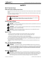
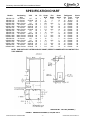
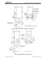
®
COUNTERTOP ICEMAKER
IMD Series
Installation Manual
Release Date: April 8, 2004
Publication Number: 638085277INS
Revision Date: February 16, 2009
Revision: C
Visit the IMI Cornelius web site at www.cornelius.com for all your Literature needs.
COUNTERTOP ICEMAKER IMD SERIES
INSTALLATION MANUAL
The products, technical information, and instructions contained in this manual are subject
to change without notice. These instructions are not intended to cover all details or variations of the equipment, nor to provide for every possible contingency in the installation,
operation or maintenance of this equipment. This manual assumes that the person(s)
working on the equipment have been trained and are skilled in working with electrical,
plumbing, pneumatic, and mechanical equipment. It is assumed that appropriate safety
precautions are taken and that all local safety and construction requirements are being
met, in addition to the information contained in this manual.
To inquire about current revisions of this and other documentation or for assistance with
any Cornelius product contact:
IMI Cornelius Inc.
www.cornelius.com
800-238-3600
Trademarks and copyrights:
Aurora, Cornelius, Decade, Hydro Boost, Sitco, Spirit, UF-1, Vanguard, Venture, Olympus,
and Vista are registered trademarks of IMI Cornelius Inc.
Optifill trademark is pending.
This document contains proprietary information and it may not be
reproduced in any way without permission from Cornelius.
Printed in U.S.A.
Copyright © 2004-2009, All Rights Reserved, IMI Cornelius Inc.
TABLE OF CONTENTS
Safety . . . . . . . . . . . . . . . . . . . . . . . . . . . . . . . . . . . . . . . . . . . . . . . . . . . . . . . . . . . . . . .
Safety Instructions . . . . . . . . . . . . . . . . . . . . . . . . . . . . . . . . . . . . . . . . . . . . . . . . . . .
Read and Follow all Safety Instructions . . . . . . . . . . . . . . . . . . . . . . . . . . . . . . .
Recognize Safety Alerts . . . . . . . . . . . . . . . . . . . . . . . . . . . . . . . . . . . . . . . . . . .
Different Types of Alerts . . . . . . . . . . . . . . . . . . . . . . . . . . . . . . . . . . . . . . . . . . .
Safety Tips . . . . . . . . . . . . . . . . . . . . . . . . . . . . . . . . . . . . . . . . . . . . . . . . . . . . . . . .
CO2 (Carbon Dioxide) Warning . . . . . . . . . . . . . . . . . . . . . . . . . . . . . . . . . . . . . . . .
Shipping And Storage . . . . . . . . . . . . . . . . . . . . . . . . . . . . . . . . . . . . . . . . . . . . . . . .
1
1
1
1
1
1
1
1
Specification Chart . . . . . . . . . . . . . . . . . . . . . . . . . . . . . . . . . . . . . . . . . . . . . . . . . . . . 2
Installation Instructions . . . . . . . . . . . . . . . . . . . . . . . . . . . . . . . . . . . . . . . . . . . . . . . .
Remove Icemaker from Carton . . . . . . . . . . . . . . . . . . . . . . . . . . . . . . . . . . . . . . . . .
Cabinet Removal . . . . . . . . . . . . . . . . . . . . . . . . . . . . . . . . . . . . . . . . . . . . . . . . . . . .
Preparation of Installation Site . . . . . . . . . . . . . . . . . . . . . . . . . . . . . . . . . . . . . . . . .
Water Inlet Hook-up . . . . . . . . . . . . . . . . . . . . . . . . . . . . . . . . . . . . . . . . . . . . . . . . .
Electrical Supply . . . . . . . . . . . . . . . . . . . . . . . . . . . . . . . . . . . . . . . . . . . . . . . . . . . .
Drain Connection . . . . . . . . . . . . . . . . . . . . . . . . . . . . . . . . . . . . . . . . . . . . . . . . . . .
Auger Engagement . . . . . . . . . . . . . . . . . . . . . . . . . . . . . . . . . . . . . . . . . . . . . . . . . .
Initial Start Up, Checks & Adjustment Instructions . . . . . . . . . . . . . . . . . . . . . . . . . .
4
4
4
4
4
4
5
5
5
Guide To Service . . . . . . . . . . . . . . . . . . . . . . . . . . . . . . . . . . . . . . . . . . . . . . . . . . . . . .
Icemaker Cleaning and Sanitizing Procedures . . . . . . . . . . . . . . . . . . . . . . . . . . . . .
Maintenance . . . . . . . . . . . . . . . . . . . . . . . . . . . . . . . . . . . . . . . . . . . . . . . . . . . . . . .
Monthly . . . . . . . . . . . . . . . . . . . . . . . . . . . . . . . . . . . . . . . . . . . . . . . . . . . . . . . . . . .
Quarterly . . . . . . . . . . . . . . . . . . . . . . . . . . . . . . . . . . . . . . . . . . . . . . . . . . . . . . . . . .
Semi-Annually . . . . . . . . . . . . . . . . . . . . . . . . . . . . . . . . . . . . . . . . . . . . . . . . . . . . . .
7
7
7
7
7
8
Water Level Control . . . . . . . . . . . . . . . . . . . . . . . . . . . . . . . . . . . . . . . . . . . . . . . . . . . 9
How Water Level Control Works . . . . . . . . . . . . . . . . . . . . . . . . . . . . . . . . . . . . . . . . 9
Purpose of Water Level Control . . . . . . . . . . . . . . . . . . . . . . . . . . . . . . . . . . . . . . . . 9
To Replace Water Level Control . . . . . . . . . . . . . . . . . . . . . . . . . . . . . . . . . . . . . . . . 9
To Replace Water Level Safety Switch . . . . . . . . . . . . . . . . . . . . . . . . . . . . . . . . . . . 9
Ice Level Control . . . . . . . . . . . . . . . . . . . . . . . . . . . . . . . . . . . . . . . . . . . . . . . . . . . . 9
Refrigeration System Adjustments . . . . . . . . . . . . . . . . . . . . . . . . . . . . . . . . . . . . . 10
Expansion Valve . . . . . . . . . . . . . . . . . . . . . . . . . . . . . . . . . . . . . . . . . . . . . . . . 10
Adjustment and Troubleshooting . . . . . . . . . . . . . . . . . . . . . . . . . . . . . . . . . . . . . . 10
Condenser Modulating Valve . . . . . . . . . . . . . . . . . . . . . . . . . . . . . . . . . . . . . . . . . 11
Condenser Modulating Valve Removal . . . . . . . . . . . . . . . . . . . . . . . . . . . . . . . . . . 11
Gear Motor . . . . . . . . . . . . . . . . . . . . . . . . . . . . . . . . . . . . . . . . . . . . . . . . . . . . . . . 12
Shaft Seal Installation and Replacement (FIGURE 7) . . . . . . . . . . . . . . . . . . . . . . 12
Auger & Extruding Head Removal . . . . . . . . . . . . . . . . . . . . . . . . . . . . . . . . . . . . . 13
Installation and Shaft Seal Replacement (FIGURE 9) . . . . . . . . . . . . . . . . . . . . . . 13
Upper Nut and Bearings . . . . . . . . . . . . . . . . . . . . . . . . . . . . . . . . . . . . . . . . . . . . . 13
To Replace Bearings . . . . . . . . . . . . . . . . . . . . . . . . . . . . . . . . . . . . . . . . . . . . . . . . 14
Troubleshooting Compressor . . . . . . . . . . . . . . . . . . . . . . . . . . . . . . . . . . . . . . . . . 14
Electrical Checkout . . . . . . . . . . . . . . . . . . . . . . . . . . . . . . . . . . . . . . . . . . . . . . . . .
Overload Check - FIGURE 10 . . . . . . . . . . . . . . . . . . . . . . . . . . . . . . . . . . . . . . . . .
Compressor Check - FIGURE 11 . . . . . . . . . . . . . . . . . . . . . . . . . . . . . . . . . . . . . .
Capacitor Check . . . . . . . . . . . . . . . . . . . . . . . . . . . . . . . . . . . . . . . . . . . . . . . . . . .
Troubleshooting Gear Motors . . . . . . . . . . . . . . . . . . . . . . . . . . . . . . . . . . . . . . . . .
The Gearmotor will not run . . . . . . . . . . . . . . . . . . . . . . . . . . . . . . . . . . . . . . . .
The Gearmotor Starts but Trips Repeatedly on the Overload Protector . . . . . .
The Motor Runs but Output Shaft does not Rotate . . . . . . . . . . . . . . . . . . . . . .
Overload Check . . . . . . . . . . . . . . . . . . . . . . . . . . . . . . . . . . . . . . . . . . . . . . . .
Motor Check . . . . . . . . . . . . . . . . . . . . . . . . . . . . . . . . . . . . . . . . . . . . . . . . . . .
14
15
15
15
15
15
15
15
15
16
Safety Controls . . . . . . . . . . . . . . . . . . . . . . . . . . . . . . . . . . . . . . . . . . . . . . . . . . . . . . 17
Guide to Good Ice . . . . . . . . . . . . . . . . . . . . . . . . . . . . . . . . . . . . . . . . . . . . . . . . . . . . 18
Countertop Icemaker IMD Series Installation Manual
SAFETY
SAFETY INSTRUCTIONS
Read and Follow all Safety Instructions
Read and follow all safety instructions in this manual and on the machine (decals, labels, and laminated
cards).
Read and understand all applicable OSHA (Occupation Safety and Health Administration) safety regulations before operating the machine.
Recognize Safety Alerts
This is the safety alert symbol. When you see it in this manual or on the machine be
alert to the potential of personal injury or damage to the machine.
Different Types of Alerts
There are three types of safety alerts:
DANGER — Indicates an immediate hazardous situation which if not avoided WILL result in serious injury, death, or equipment damage.
WARNING — Indicates a potentially hazardous situation which, if not avoided, COULD result in
serious injury, death, or equipment damage.
CAUTION — Indicates a potentially hazardous situation which, if not avoided, MAY result in
minor or moderate injury or equipment damage.
SAFETY TIPS
• Carefully read all safety messages in this manual and safety signs on the machine.
• Keep safety signs in good condition and replace missing or damaged safety signs.
• Learn how to operate the machine and how to use the controls properly.
• Do not let anyone operate the machine without proper training. This appliance is not intended for use
by very young children or infirm persons without supervision. Young children should be supervised to
ensure that they do not play with the appliance.
• Keep your machine in proper working condition and do not allow unauthorized modifications to the
machine.
CO2 (CARBON DIOXIDE) WARNING
WARNING — CO2 Displaces Oxygen. Strict Attention must be observed in the prevention of
CO2 gas leaks in the entire CO2 and soft drink system. If a CO2 gas leak is suspected, particularly
in a small area, immediately ventilate the contaminated area before attempting to repair the leak.
Personnel exposed to high concentration of CO2 gas will experience tremors which are followed
rapidly by loss of consciousness.
SHIPPING AND STORAGE
CAUTION — Before shipping, storing, or relocating the Unit, syrup systems must be sanitized
and all sanitizing solution must be purged from the syrup systems. All liquids, after sanitizing, must
be purged from the unit. A freezing ambient environment will cause residual sanitizing solution or
water remaining inside the Unit to freeze resulting in damage to the internal components.
© 2004-2009, IMI Cornelius Inc.
-1-
Publication Number: 638085277INS
Countertop Icemaker IMD Series Installation Manual
SPECIFICATION CHART
Models
IMD300-15A
IMD302-15A
IMD300-30A
IMD300-30W
IMD301-30A
IMD301-30W
IMD302-30A
IMD302-30W
IMD600-30A
IMD600-30A
IMD601-30A
IMD601-30W
IMD602-30W
IMD600-90A
IMD600-90W
IMD601-90A
IMD601-90W
IMD602-90A
IMD602-90W
Condensing
Unit
Air Cooled
Air Cooled
Air Cooled
Water Cooled
Air Cooled
Water Cooled
Air Cooled
Water Cooled
Air Cooled
Water Cooled
Air Cooled
Water Cooled
Water Cooled
Air Cooled
Water Cooled
Air Cooled
Water Cooled
Air Cooled
Water Cooled
VAC
Hz
Ph
115
220/240
115
115
208/230
208/230
220/240
220/240
115
115
208/230
208/230
220/240
115
115
208/230
208/230
220/240
220/240
60
50
60
60
60
60
50
50
60
60
60
60
50
60
60
60
60
50
50
1
1
1
1
1
1
1
1
1
1
1
1
1
1
1
1
1
1
1
Comp
RLA
6
3
10.1
10.1
5.7
5.7
5.3
5.3
12
12
7.7
7.7
8.2
12
12
7.7
7.7
8.2
8.2
Fan
Amps
0.82
.5
1
N/A
1
N/A
0.5
N/A
1
N/A
1
N/A
N/A
1
N/A
1
N/A
0.5
N/A
Grmtr
Amps
2
1.6
2
2
1.6
1.6
1.6
1.6
2
2
1.6
1.6
1.6
2
2
1.6
1.6
1.6
1.6
Refrigerant
Oz.
Type
12
R134a
12
R134a
28
R404A
13
R404A
28
R404A
13
R404A
28
R404A
13
R404A
28
R404A
14
R404A
28
R404A
14
R404A
14
R404A
24
R404A
14
R404A
24
R404A
14
R404A
24
R404A
14
R404A
Circuit
Fuse
15
15
20
20
20
20
20
20
20
20
20
20
20
20
20
20
20
20
20
NOTE: FOR UNITS NOT LISTED IN ABOVE CHART, REFER TO NAMEPLATE OR CONTACT FACTORY SERVICE.
SHIPPING WT. 189 LBS. (APPROX.)
FIGURE 1. DIMENSION DRAWING (15 LB.) IMD 300-15
Publication Number: 638085277INS
-2-
© 2004-2009, IMI Cornelius Inc.
Countertop Icemaker IMD Series Installation Manual
S HIP P ING WT. (IMD300-- 30) 220 L B S . (A P P R OX.)
S HIP P ING WT. (IMD600-- 30) 240 L B S . (A P P R OX.)
FIGURE 2. DIMENSION DRAWINGS (30 LBS.) IMD 300-30 AND IMD 600-30
S HIP P ING WT. 225 L B S . (A P P R OX.)
FIGURE 3. DIMENSION DRAWINGS (90 LBS.) IMD600-90
© 2004-2009, IMI Cornelius Inc.
-3-
Publication Number: 638085277INS
Countertop Icemaker IMD Series Installation Manual
INSTALLATION INSTRUCTIONS
REMOVE ICEMAKER FROM CARTON
1.
2.
Keep unit in the upright position, remove carton and pallet from unit and inspect unit for damage.
Upon inspection of unit, if any damage is found, file a claim with carrier immediately.
Locate Startup Card either on outside of container or on plastic liner. Fill in proper information and
send one copy to factory, and other copy to Distributor. Postage is prepaid.
CABINET REMOVAL
1.
2.
3.
4.
5.
6.
Locate and remove the (2) screws from under the front cover. Lift cover forward and up to remove.
Lift up front edge of top cover. Slide back about 1/2 inch and remove.
Remove (6) screws from the front of the machine.
Remove side panels by sliding the front edge out and then back slightly to disengage.
Remove the front splash panel by lifting slightly to disengage the front, then tilt forward and remove.
Remove bin top and remove shipping insert.
PREPARATION OF INSTALLATION SITE
1.
2.
The refrigeration system on air cooled units requires airflow, so a well ventilated area should be
chosen. A minimum of (6) inches must be maintained, free of any obstruction, for air intake. A minimum of (4) inches clearance is required of air exhaust.
With template provided make the necessary provisions in the counter for water, drain and the electrical hook-up. Provisions are available for rear and bottom connections of water and electrical.
Use hole plugs provided to plug unused holes.
WATER INLET HOOK-UP
Water Inlet - Fitting is a 1/4” SAE male flare located at the rear of the unit. Connect water supply
with a 1/4” or larger copper or flexible tubing.
2. Water Pressure - Unless otherwise specified, the unit is designed to operate on water pressures
between 10 P.S.I. and 90 P.S.I. (NOTE: for pressures above 90 P.S.I. a regulator must be installed).
3. Water Cooled Condensers
A. Inlet to modulating valve uses 3/8” FPT. Use separate 3/8” or larger water line.
B. Outlet is 3/8” FPT.
4. Filter Conditioner are recommended on supply lines to icemakers. Never run the water supply to
water cooled Condenser through Filter/Conditioner, it uses up the cartridge unnecessarily and a
saturated cartridge can starve the icemaker causing premature component damage. Separate
water supplies are recommended.
NOTE: Unit must be installed per local plumbing code.
1.
ELECTRICAL SUPPLY
Power Access - Is provided by way of a 7/8” dia. hole in both the base and the rear panel. Route
incoming power in conduit, to icemaker electrical control box. Make connections to wires provided
in control box and ground lug/screw. Plug unused hole.
2. Fused Line - Should be a dedicated circuit checked and sized according to electrical rating shown
on unit nameplate.
NOTE: Unit must be installed per local electrical code.
1.
Publication Number: 638085277INS
-4-
© 2004-2009, IMI Cornelius Inc.
Countertop Icemaker IMD Series Installation Manual
DRAIN CONNECTION
1.
2.
3.
4.
5.
6.
Install splash panel on machine and hold in place with (2) screws. Do not tighten at this time.
Remove drain tray mounting bracket from their shipping carton.
Clip the drain try mounting bracket onto the bottom of the splash panel in the brackets provided.
Hook the drain tray into the splash panel and onto the mounting bracket.
Push the drain elbow securely onto the drain tray. Do not glue in place.
Complete drain hookup according to the instructions provided with unit.
FIGURE 4. FLOAT ASSEMBLY
NOTE: Steps 7 and 8 to be completed only after all start up checks and adjustments are performed.
7. Replace side panels tightening all (6) screws (including splash panel screws left loose).
8. Replace top panel and front cover and secure with (2) screws.
NOTE: In those cases where the unit is base mounted and not on legs it should be sealed all
around the base with NSF listed sealant. (IMI Wilshire P/N 04815-B).
AUGER ENGAGEMENT
Be certain that auger is fully engaged to lower drive and that extruding head is fully engaged to evaporator.
INITIAL START UP, CHECKS & ADJUSTMENT INSTRUCTIONS
NOTE: Do not start unit before completing above Installation Instructions.
Turn on water supply and main power switch (located on top of electric box). All IMD 30 lb. and 90 lb.
series units are equipped with a 45 second delay timer. This means that the refrigeration system will not
start until 45 seconds of dispense are accumulated in the timer. Start the refrigeration system by
depressing the ice dispense button for 45 seconds. Make the following system checks:
NOTE: If unit will not start be sure water reservoir is full. Low water safety control must be properly adjusted to start and shut down unit. If water level drops below bottom of reservoir, unit
must shut down. Adjustment is made by moving magnet up or down.
Water Level - If necessary adjust Float by bending float arm up or down as needed, push float assembly
down until unit stops running. Release float and unit will restart. Keep water in reservoir at level line
while unit is in operation. See FIGURE 4.
© 2004-2009, IMI Cornelius Inc.
-5-
Publication Number: 638085277INS
Countertop Icemaker IMD Series Installation Manual
Low Water Safety Control - Adjust magnet by bending magnet arm as shown in FIGURE 4 to shut
down unit if the water level drops below the line on the side of the reservoir.
Bin Control - Remove four screws from top of bin cover and lift cover so bin control plate can be manually lifted until unit shuts down. Release plate and unit will restart (On IMD300-30, IMD600-30, and
IMD600-90 the dispense button must be depressed for 45 seconds before until will start). Replace
screws.
Dispense Switch and Mechanism - By depressing the dispense switch, the dispense mechanism door
on the storage bin will open, and chain, sprockets, and agitator will rotate counterclockwise.
NOTE: If any of these checks or adjustments cannot be achieved, refer to Troubleshooting Section of this manual or call our Technical Support Center for assistance at 1-800-238-3600.
Publication Number: 638085277INS
-6-
© 2004-2009, IMI Cornelius Inc.
Countertop Icemaker IMD Series Installation Manual
GUIDE TO SERVICE
ICEMAKER CLEANING AND SANITIZING PROCEDURES
Do not use any of the ice made during cleaning operations.
Clean and sanitize ice storage area when cleaning icemaker.
1.
2.
3.
4.
5.
6.
7.
8.
9.
Turn machine off.
Shut off water supply.
Remove ice from storage bin.
Mix approved cleaner (2 gallons as directed). Recommended cleaner: Calgon Corp. of Virginia
Chemicals, ice machine cleaner. Mixture: 3-1/3 ounces per gallon of water. Do not use nickel safe
cleaners.
Turn machine on and add cleaner solution to water level control (float reservoir) until 2 gallons have
been used.
Turn on water supply and run machine for 15 minutes.
Turn off machine and remove and discard all ice.
Sanitize using household liquid bleach (50 ppm chlorine). Mixture: 1 fluid ounce per gallon room
temperature water. 2 minute exposure time.
Sanitize pre-cleaned inside areas of storage bin liner, door frame, door, as well as exposed surfaces
of the evaporator assembly and bin shutoff assembly with sanitizing solution and allow to air dry.
MAINTENANCE
Preventive maintenance can increase the trouble free life of your icemaker. Many authorized service
agencies offer service contracts for your icemaker. Contact your local distributor for further information.
MONTHLY
1.
2.
Clean the condenser. Use a brush, vacuum cleaner or blow from inside with air or CO2 gas. If unit
is provided with and air filter, clean or replace.
Inspect water feed reservoir at least once a month until a definite pattern for cleaning and sanitizing
has been established.
QUARTERLY
This is the maximum period of time between cleaning and sanitizing the icemaker. In addition to recommended monthly procedure, and if a more frequent cleaning and sanitizing pattern has not been established, unit must be cleaned and sanitized.
© 2004-2009, IMI Cornelius Inc.
-7-
Publication Number: 638085277INS
Countertop Icemaker IMD Series Installation Manual
SEMI-ANNUALLY
Semi-Annually in addition to all previously established service procedures perform the following:
1.
2.
3.
4.
5.
6.
7.
Check for water leaks in tube connections, water fittings, and lower icemaker water seal.
Check drain tubes for clogs and “aged” tubes. Replace if tubes are stained or brittle.
Check for signs of condensation. Clean where necessary and replace insulation properly.
Check safety circuits for proper operation.
Check refrigeration system.
Check unit for abnormal noise. Tighten machine and cabinet screws, if necessary.
Check white upper bearings on auger assembly. If bearings are less than 1/16” thick, replace. See
FIGURE 5.
R E PLACE
1/16?
OK
1/16?
OK
R E PLACE
FIGURE 5. UPPER BEARING AND AUGER ASSEMBLY
NOTE: Preventive maintenance can increase the trouble-free life of your icemaker. Failure to
perform preventive maintenance could void your equipment warranty.
Publication Number: 638085277INS
-8-
© 2004-2009, IMI Cornelius Inc.
Countertop Icemaker IMD Series Installation Manual
WATER LEVEL CONTROL
HOW WATER LEVEL CONTROL WORKS
When water is introduced through the inlet fitting the float rises. The float pushes against a lever which in
turn forces the poppet assembly against the inlet fitting valve seat which seals the water off, (see FIGURE 4). Before the water inlet is sealed the safety switch is operated. In the event of a water failure the
float would drop down and operate the safety switch to shut off the machine.
If water level control will not shut off and seal at level as indicated, be sure inlet pressure does not
exceed recommended factory operating range.
Under ordinary circumstances adjustment should not be necessary providing it was properly adjusted
when unit was installed or relocated. If, however, the control becomes inoperative, repair or replace.
See Start-Up Adjustment.
PURPOSE OF WATER LEVEL CONTROL
1.
2.
3.
To automatically maintain proper water level in the evaporator when unit is running and making ice.
A safety switch is operated in the event of an interruption in water supply. The switch shuts off the
electrical power to the icemaker and its refrigeration system. Switch will reset as soon as cause of
water failure has been corrected and proper water level in icemaker has again been reached.
The transparent bowl not only provides a visible check of water level, but also is a good guide to the
internal conditions which exist within the icemaker assembly itself. (See Cleaning Procedure).
TO REPLACE WATER LEVEL CONTROL
1.
2.
3.
4.
5.
Shut off the water supply. Shut off the main power switch or unplug the ice dispenser from electrical
outlet.
Remove the flexible tubing from bottom of water level control and drain water from water level control and evaporator.
Remove flexible tubing at bottom of water level bowl connected to the overflow.
Hold water inlet fitting with proper tool to prevent it from rotating when disconnecting the water inlet.
Remove wing nut holding water control to its mounting bracket. Control can be removed by lifting
straight up.
TO REPLACE WATER LEVEL SAFETY SWITCH
1.
2.
3.
Shut off main power switch or unplug the ice dispenser from electrical outlet.
Unplug molex connector connecting switch to electrical box.
Remove the 2 screws anchoring the water level safety switch to the bottom of the water level control
mounting bracket.
ICE LEVEL CONTROL
The ice level control assembly is secured to the top of the ice storage container cover. The cover is
secured to the storage container with four screws. The level control switch is operated by a plate assembly located beneath the diaphragm. When the plate assembly is down due to lack of ice in storage container, electrical impulse is sent to compressor, starting the ice making cycle. As ice level increases in
storage container, the plate assembly is pushed up. When storage container is full, it de-actuates the
switch, stopping the compressor and ice making cycle.
© 2004-2009, IMI Cornelius Inc.
-9-
Publication Number: 638085277INS
Countertop Icemaker IMD Series Installation Manual
The operating positions of the switch are fixed, no adjustments are necessary. If switch replacement
becomes necessary, simply disconnect cable at connector, remove wires from switch.
Temperature/Pressure Charts*
Air Temperature
10 lbs. Discharge Pressure
Water Temperature
50o
60o
70o
80o
90o
100o
40o
80
92
114
124
161
187
IMD300-15
65o
85
97
120
120
167
193
90o
90
102
124
147
171
195
IMD300-30
65o
166
192
218
249
279
313
40o
162
188
214
245
275
309
90o
168
194
220
251
281
315
IMD600-30 & IMD600-90
40o
65o
90o
174
177
180
202
205
208
230
233
236
265
269
272
300
304
307
328
334
340
NOTE: The thermostatic expansion valve is non-adjustable on all models.
REFRIGERATION SYSTEM ADJUSTMENTS
A complete understanding of the icemaker and hermetic refrigeration system is necessary before any
adjustments are made. The refrigeration technician must use high and low side pressure readings,
water, and air temperatures, plus general conditions of cleanliness to assess the refrigeration system status when making any adjustments.
All icemaker products are tested and adjusted at the factory prior to shipment where the ambient temperature ranges from 65oF to 90oF, depending on the season of the year.
Whenever a new icemaker is initally installed and started-up, it is imperative that the start-up operator
make the following checks and readjustments for local conditions.
EXPANSION VALVE
You will find a thermal expansion valve on icemakers, which is used to control the amount of refrigerant
flowing through the evaporator. Improperly installed or defective expansion valves may cause low production, soft ice, squeaking from evaporator and excessive load inside evaporator.
By using general refrigeration troubleshooting along with the pressure charts, you can easily determine
whether or not the expansion valve is working properly.
ADJUSTMENT AND TROUBLESHOOTING
When troubleshooting the expansion valve, you must:
1.
Be sure you have adequate water flowing into the evaporator, a clean and properly ventilated condenser, and the system is properly charged and free of any restrictions. Also be sure compressor is
operating properly.
2. Take reservoir water temperature and air temperature from condenser inlet and determine at what
pressure unit should be running. On machines equipped with thermostatic valve there is NO adjustment. If correct pressure cannot be obtained, be sure system has time to stabilize, 10-15 minutes.
3. Be sure sensing bulb is located at outlet side of evaporator about 3-4 inches away from evaporator
and be sure to insulate well and clamp tightly to tubing. If system pressures are still not adequate,
take a second water and air temperature reading and go over other parts of the system for possible
problems. If proper charge is questionable evacuate and recharge to nameplate and leak check. If
valve still malfunctions replace valve.
Use general refrigeration system practices when replacing and recharging unit. After new valve is in
place, go through previous monitored adjustments and troubleshooting to be sure valve is functioning
properly.
Publication Number: 638085277INS
- 10 -
© 2004-2009, IMI Cornelius Inc.
Countertop Icemaker IMD Series Installation Manual
NOTE: On water cooled units adjust condenser modulating valve before troubleshooting expansion valve.
CAUTION: Very high discharge pressure is present in system. Quick disconnects on your gages
will minimize Danger and loss of refrigerant. Comply with federal regulations for reclaiming
refrigerant.
CONDENSER MODULATING VALVE
The reason for using a water modulating valve is to supply the correct amount of water to the condenser
to maintain the proper operating pressure in the refrigeration system high side. The flow of water through
the valve is increased as the high side pressure rises and decreases as high side pressure lowers.
To calibrate the amount of water flow with the refrigeration system high side pressure, turn adjustment
screw located on end of valve opposite of bellows (see FIGURE 6). Turn screw counterclockwise to
raise opening point. Opening point of valve should be set to maintain proper operating pressure in refrigeration system high side. Refer to Pressure Chart on Page 11. Closing point of valve should be set low
enough to close valve during compressor stand by periods.
NOTE: Cold water will absorb more heat faster than warm water. The water flow will therefore
automatically increase as inlet temperature increase.
FIGURE 6. ADJUSTMENT SCREW
CONDENSER MODULATING VALVE REMOVAL
1.
2.
3.
4.
5.
6.
7.
8.
9.
Disconnect power to unit, then shut off water supply to condenser and reclaim refrigerant from system.
Remove inlet water line from Condenser modulating Valve. Also remove tube from refrigerant high
side line.
Remove Condenser Modulating Valve and bracket.
Remove valve from bracket.
Replace Condenser Modulating Valve by reversing Steps 2 thru 4.
Recharge unit with refrigerant per nameplate.
Turn power and water ON to unit.
With unit running adjust modulating valve to proper setting.
Go through a complete system check.
© 2004-2009, IMI Cornelius Inc.
- 11 -
Publication Number: 638085277INS
Countertop Icemaker IMD Series Installation Manual
GEAR MOTOR
The gear motor is equipped with a start relay and a manual reset overload. When current is applied, the
relay energizes and completes the circuit to the start winding. The motor reaches a predetermined
speed and the relay drops out, disconnecting the start winding. The run winding remains in the circuit as
long as current is applied.
The purpose of the overload is to automatically shut off the motor in the event of a mechanical bind of the
transmission, an overload condition within the evaporator or an electrical malfunction. It does this by
sensing amperage draw. If the motor stalls the start relay would energize and stay energized. The
amperage would surge to 5 to 6 times greater than normal draw. In this event the overload would shut off
the transmission in 4 to 8 seconds.
If the motor is subjected to an abnormal load, but does not reach stall condition, the overload will react,
but over a greater period of time. The reaction time depends upon the amperage to which it is subjected.
The overload, through the safety circuit, also shuts off the compressor.
Refer to Troubleshooting Guide.
FIGURE 7. IMD 300 SHAFT SEAL
FIGURE 8. AUGER AND EXTRUDING HEAD REMOVAL
SHAFT SEAL INSTALLATION AND REPLACEMENT (FIGURE 7)
1.
2.
3.
4.
Place shaft seal locator seat over gear motor output shaft, embossed side down, and push down
until shaft seal seat rests flush on top of gear motor.
Place rubber coated ceramic seal (important: ceramic face up) over output shaft and push down
until seal rests on top of the shaft seal seat. (Lubricate rubber on ceramic seal with [#06195] rubber
lubricant.)
Place shaft seal with carbon face down (spring up) over output shaft and push (gently) downward
until seal rests on carbon face of output shaft seal.
Push down on the washer compressing the spring on the output shaft seal. While holding the seals
(down) in place slide the E-ring into the groove on the output shaft.
Publication Number: 638085277INS
- 12 -
© 2004-2009, IMI Cornelius Inc.
Countertop Icemaker IMD Series Installation Manual
AUGER & EXTRUDING HEAD REMOVAL
1.
2.
3.
4.
5.
Disconnect unit from power supply.
Remove storage container cover and put aside.
Turn off water supply to icemaker.
After ice has melted from head take hold of the auger nut and lift straight up to disengage from icemaker.
When replacing the auger assembly, make certain that both the auger engages the output shaft
drive and the extruding head ribs engage the evaporator tube collar. See FIGURE 8.
FIGURE 9. IMD 600 SHAFT SEAL
INSTALLATION AND SHAFT SEAL REPLACEMENT (FIGURE 9)
1.
2.
3.
4.
Place shaft seal locator seat over gear motor output shaft, embossed side down, and push down
until shaft seal seat rests flush on top of gear motor.
Place rubber coated ceramic seal (important: ceramic face up) over output shaft and push down
until seal rests on top of the shaft seal seat. (Lubricate rubber on ceramic seal with [#06195] rubber
lubricant.)
Place shaft seal with carbon face down (spring up) over output shaft and push (gently) downward
until seal rests on carbon face of the output shaft seal.
Place flat washer over output shaft and let rest on the output shaft seal. Push down on the washer
compressing the spring on the output shaft seal. While holding the seals (down) in place slide the
E-ring into the groove on the output shaft.
UPPER NUT AND BEARINGS
The upper bearings located on top of the auger is used to absorb the force between the auger and
extruding head.
The bearings are 3/32” thick. When they wear below 1/16” they should be replaced. Bearings to
be inspected for wear during quarterly maintenance. See FIGURE 8.
© 2004-2009, IMI Cornelius Inc.
- 13 -
Publication Number: 638085277INS
Countertop Icemaker IMD Series Installation Manual
TO REPLACE BEARINGS
1.
2.
3.
4.
5.
6.
7.
Dispense all ice from unit.
Disconnect unit from electrical power.
Remove panels.
Unplug Dispense Motor and Ice Level Switch.
Remove four screws holding dispense cover in place.
Remove dispense cover assembly.
Use an open end wrench on auger nut connected to bearing and turn and turn counterclockwise to
remove assembly.
8. Remove worn bearings. Replace with new bearings and then reinstall assembly.
NOTE: If auger turns with nut, remove cover on top of gear motor stator and hold rotor while
loosening nut.
9.
Reconnect power to icemaker.
TROUBLESHOOTING COMPRESSOR
Basically the compressor problems can be narrowed down to three areas of checkout.
1.
THE COMPRESSOR WILL NOT RUN
• No voltage to the compressor terminals - check circuit.
• Low voltage - below 90% of nameplate rated voltage.
• Problems in the compressor electrical circuit. See Electrical Checkout Instructions.
2.
THE COMPRESSOR STARTS BUT TRIPS REPEATEDLY ON THE OVERLOAD PROTECTOR
• Check for proper fan operation and clean condenser.
• Check the compressor suction and discharge pressures.
• Voltage - The voltage should be within 10% of the rated nameplate voltage.
• High compressor amperage draw, it should never exceed 120% of the rated nameplate amperage. See Electrical Checkout Instructions.
3.
THE COMPRESSOR RUNS BUT WILL NOT REFRIGERATE
• Check the compressor suction and discharge pressures. See Chart on Page 12.
ELECTRICAL CHECKOUT
1.
2.
3.
Be sure the unit is disconnected from the power source. Remove the compressor electrical box
cover. Check for obvious damage and loose wires.
Disconnect the fan motor leads. Since capacitors store energy, short the capacitor with a screwdriver. This will prevent shocks.
Disconnect the compressor terminal wires.
FIGURE 10. OVERLOAD CHECK
Publication Number: 638085277INS
FIGURE 11. COMPRESSOR CHECK
- 14 -
© 2004-2009, IMI Cornelius Inc.
Countertop Icemaker IMD Series Installation Manual
OVERLOAD CHECK - FIGURE 10
4.
Using a volt-ohm meter check the continuity across the overload, contacts #1 & #3. If none, wait for
unit to cool down and try again. If still no continuity, the overload protector is defective and should
be replaced.
COMPRESSOR CHECK - FIGURE 11
The resistance readings on the windings will be between 0.25 and 10.00 ohms, a meter capable of these
low readings must be used.
5.
6.
7.
8.
Check between “C” & “R”. Replace compressor if there is no continuity as the run windings are
open.
Check between “C” & “S”. Replace the compressor if there is no continuity as the start windings are
open.
Check between “C” & “R”, or “S” and shell of the compressor. If there is continuity replace the compressor as the motor is grounded.
Check between screw terminal on the overload and “C” on the compressor. Check and repair the
lead or connections if there is no continuity.
CAPACITOR CHECK
9. Check or replace start capacitor, disconnect bleed resistor before checking for shorted capacitor.
10. Check or replace run capacitor (if supplied) check or shorted capacitor or either terminal grounded
to case.
TROUBLESHOOTING GEAR MOTORS
Basically, Gear motor problems can be narrowed down to three areas of checkout.
The Gearmotor will not run
1.
2.
3.
No voltage to the transmission terminals - check external circuit.
Low voltage - check supply.
Problems in the gear motor electrical circuit. See FIGURE 12.
The Gearmotor Starts but Trips Repeatedly on the Overload Protector
1.
2.
Voltage - high or low voltage can cause the overload to trip.
High Gear motor amperage draw, see Specification Chart for ratings and Troubleshooting Guide.
The Motor Runs but Output Shaft does not Rotate
1. Replace defective gear motor.
CAUTION: Be sure unit is disconnected from the power source. Disconnect the transmission
cable.
Overload Check
1.
2.
3.
Allow motor to cool and reset overload if necessary.
Remove motor end bell and stator, if necessary.
Check terminals 1 and 3 on overload. No continuity replace overload. Use a volt-ohm meter. See
FIGURE 10 and FIGURE 11.
NOTE: Gear motor and related components can be checked from Pin Connector. See FIGURE
12.
© 2004-2009, IMI Cornelius Inc.
- 15 -
Publication Number: 638085277INS
Countertop Icemaker IMD Series Installation Manual
Motor Check
The resistance readings on the windings will be between 5 to 25 ohms. A meter capable of these low
readings must be used. The Start Relay cover must be removed.
If no continuity on start or run winding test, replace stator. If continuity on grounded motor test, replace
stator.
FIGURE 12. PIN NUMBERS
Publication Number: 638085277INS
- 16 -
© 2004-2009, IMI Cornelius Inc.
Countertop Icemaker IMD Series Installation Manual
SAFETY CONTROLS
Your Icemaker unit has several safety and control devices incorporated into its design.
WARNING: None of the below described devices should ever be “bypassed” to allow the
unit to function.
The safety and control system shut-off devices are:
FIGURE 13.
1.
2.
3.
4.
5.
6.
Low water shut off reed switch located in icemaker float assembly. (Automatic reset type).
Gear motor thermal overload, manual reset type (red button on motor). See FIGURE 13.
Compressor thermal overload, automatic reset type.
Main service switch located on top of the control box.
Hopper shut-off.
High pressure cut out (water cooled only).
WARNING: Do not reset gear motor overload if ice is present in the evaporator.
© 2004-2009, IMI Cornelius Inc.
- 17 -
Publication Number: 638085277INS
Countertop Icemaker IMD Series Installation Manual
GUIDE TO GOOD ICE
CUSTOMER COMMENTS
“It runs but the ice is too soft.”
“The icemaker is not producing
enough ice.”
CHECK ICEMAKER LOCATION
CONDITIONS FIRST
• Proper air flow for condensing
system.
• Location too close to high units
such as coffee urns, deep fryers,
grills, etc.
• Supply water conditions
Water too warm (above 90oF.
“The ice is too wet.”
Water artificially softened above
262 ppm sodium chloride.
CHECK ICEMAKER
• Use gauges for checking suction and head pressures. See
manual for correct reading and
conditions. Check frost line and
sight glass.
• Check water level for proper
adjustment and restrictions. See
Manual.
• Check evaporator assembly
for worn parts, bearings, scored
evaporator and auger, bad
expansion valve, ect.
Normal water supply too high in
total dissolved solids (above 500
PPM).
OVER COMPRESSION
“It makes too much noise.” (With
this comment the ice is usually
extremely hard and larger than
normal.)
Publication Number: 638085277INS
• Check to see if noise objection
is normal fan and air flow noise.
• Supply water conditions.
Water too cold (below 50oF).
(Possibly running from pre-cooler.)
• Obstructions partially blocking
ice exit from top of evaporator.
• Check fan and fan shroud.
- 18 -
• Check for loose parts and
screws rattling.
• Check evaporator assembly
for worn parts, bearings, scored
evaporator and auger, bad
expansion valve, etc.
© 2004-2009, IMI Cornelius Inc.
© 2004-2009, IMI Cornelius Inc.
Too much
refrigerant in
system.
Evacuate and
recharge system.
Clean condenser.
Non-condensible
in system.
Check electrical wiring in con
trol box for loose connec
tions.
Check for failed service
switch or relay.
Check power to machine.
NO POWER
- 19 Plugged
liquid line
dryer.
Replace
dryer.
Evacuate
and
recharge
system.
Check for
leaks.
Condenser
dirty or
restricted.
Low on
refrigerant.
Check electrical circuit
to fan motor.
Check fan motor.
Condenser
fan not
running.
Hold dispense button for 45
secongs
Check for faulty dispense
timer
Dispense Timer Keeping
Icemaker Off
Replace
valve.
Evacuate
and
recharge
system.
Plugged or
faulty TXV.
Check drive on
gearmotor.
Check for
kinks or
damage to
liquid line.
Restricted
liquid line.
Check gears in
gearbox.
No
Check if
auger is
turning.
Icemaker
froze up.
Clean
and
tighten.
Bulb
loose.
Valve
stuck
open.
High suction pressure
(30 lbs. or above).
TXV not
operating
properly.
Replace
valve.
LOW WATER SAFETY
SWITCH OPEN
TXV bulb
lost charge.
IMPORTANT
Icemaker runs when reset
but problem has not been
found.
Continue checking for
overload as follows to
guard against future
problems
Clean all related
drain lines.
Yes
Short run trips
again in 2 min
utes. Check gear
motor circuit.
Icemaker runs
Refer to guide
to Good Ice in
service manual.
No
Check bin switch
Check to see if ice control plate
moves freely
ICEMAKER OPERATING BUT
Soft Ice
Poor dispensing
Check
gearmotor
circuit.
Reset but
motor does
not run.
Reset
overload.
CAUTION
Clear ice from
evaporator and
auger before re
setting over
load.
No
Will not
reset
replace
overload
Overload
hot try
again.
Will not
reset.
CLEAN
see
instructions.
Yes
Check water level control
and evaporator water tube
for lime build up restriction.
GEARMOTOR OVERLOAD
TRIPPED
OVERLOAD GUIDE
ELECTRICAL
High or low voltage weak power lines can cause overloads on icemaker restarts
High running current. Check motor circuits and start relay - Auger delay failed.
ICEMAKER
Mechanical parts worn. Scored evaporator or auger. Worn thrust bearing.
Ice maker not turning off. Failed ice level control.
Over compression. Low water inlet temperature. Restriction in water line from
reservoir.
REFRIGERANT
Contaminated charge or bad compressor.
Low charge or gas leak.
Low suction pressure. Improper expansion valve sensing bulb. Location or insulation
and/or defective expansion valve
Replace valve
evacuate and
recharge.
Check if extruding
head is down in
evaporator tube.
Clean and
insulate.
Bulb
uninsulated.
Suction line
not
insulated.
Check bin switch
Check to see if ice con
trol plate moves freely
Storage Container Bin
Switch Open
Low suction pressure
(20 lbs. or below).
Check that water is turned on.
Check for restriction in water line.
Check incoming water pressure
(minimum 10 lbs.).
Check water safety switch.
Head
Pressure
high.
Evaporator water tube
may have an air bubble.
Clear air bubble from
tube.
Check line voltage.
Check compressor winding
& components.
Condenser fan running
but compressor not running
ICEMAKER RUNS BUT
DOES NOT MAKE ICE
TROUBLESHOOTING CHART - ICEMAKER NOT OPERATING
Countertop Icemaker IMD Series Installation Manual
Publication Number: 638085277INS
Countertop Icemaker IMD Series Installation Manual
BLK 1
2
ICE
SELECT
BRN
LIGHT
WHT
YLW
4
1
DISP.
SWITCH
WHT
2
LIGHT
WATER
SELECT
BRN
BLK
YLW
DISPENSE
MOTOR
WHT
YLW
BLK
YLW
BRN
BLK
RED
BLU
WHT
ORG
YLW
BRN
GRN
BRN
GRN
GRY
3
BRN
ORG
BLU
WATER
VALVE
DRINK FRONT
OPTION
1
WHT
BLK
5
RED
1
3
4
SERVICE
SWITCH
BLK
BLK
WHT
BLK
BLK
GRN
6
WHT
WHT
2
ANTI-FREEZE
RELAY
WHT
ELECTRICAL BOX
2
3
LOW WATER
ICE LEVEL
FAN
COMP.
L
NOT USED WITH
DRINK FRONT OPTION
DISPNSE
SOLENOID
GEAR MOTOR
4
PNK
WHT
BLK
NOT USED WITH
DRINK FRONT OPTION
1
PNK
DRINK
FRONT OPTION
120 VAC CUSTOMER HOOK-UP PER LOCAL CODE
IMD-15 WIRING DIAGRAM
FIGURE 14. SCHEMATIC IMD 300-15
Publication Number: 638085277INS
- 20 -
© 2004-2009, IMI Cornelius Inc.
Countertop Icemaker IMD Series Installation Manual
FIGURE 15. SCHEMATIC IMD 300-30, IMD 600-30, IMD 601-30, IMD 600-90, AND IMD 601-90
© 2004-2009, IMI Cornelius Inc.
- 21 -
Publication Number: 638085277INS
Countertop Icemaker IMD Series Installation Manual
FIGURE 16. SCHEMATIC IMD 302-30, IMD 602-30, AND IMD 602-90
Publication Number: 638085277INS
- 22 -
© 2004-2009, IMI Cornelius Inc.
IMI Cornelius Inc.
www.cornelius.com