1
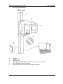
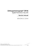
ENGLISH
Orthopantomograph® OP30
Digital Panoramic X-ray Unit
Installation and setup manual
Number 204404 rev. 5 (2010-05)
Orthopantomograph® OP30
Copyright
Contents
Document code: 204404 ver. 5 (2010-05)
Copyright © 2009 by PaloDEx Group Oy.
All rights reserved.
Documentation, trademark and the software are copyrighted
with all rights reserved. Under the copyright laws the
documentation may not be copied, photocopied, reproduced,
translated, or reduced to any electronic medium or machine
readable form in whole or part, without the prior written
permission of Instrumentarium Dental.
The original language of this manual is English.
Instrumentarium Dental reserves the right to make changes
in specification and features shown herein, or discontinue the
product described at any time without notice or obligation.
Contact your Instrumentarium Dental representative for the
most current information.
Manufactured by
Instrumentarium Dental
Nahkelantie 160 (P.O. Box 20)
FI-04300 Tuusula
FINLAND
Tel. +358 (0)10 270 2000
Fax. +358 9 851 4048
For service, contact your local distributor.
Installation and set-up manual 204404
i
Contents
ii
Orthopantomograph® OP30
Installation and set-up manual 204404
Orthopantomograph® OP30
Contents
Contents
1. Introduction..................................................................................... 1
1.1 Introduction ................................................................................................... 1
1.2 Associated documentation ............................................................................ 1
1.3 Warnings and precautions............................................................................. 2
During installation ....................................................................................... 2
During unit operation .................................................................................. 2
1.4 Unit description ............................................................................................. 3
Main parts ................................................................................................... 3
Unit controls ................................................................................................ 5
2. Pre-installation requirements ........................................................ 6
2.1 The Unit ......................................................................................................... 6
2.2 The PC .......................................................................................................... 8
2.3 The dental imaging software ........................................................................ 8
2.4 Space requirements ...................................................................................... 8
2.5 Unit dimensions ............................................................................................. 9
2.6 Fixing hole dimensions ................................................................................ 10
2.7 Fixing hardware and Installation and setup tools .........................................11
Fixing hardware .........................................................................................11
Installation tools .........................................................................................11
Calibration and setup tools ........................................................................11
3. Installing the unit .......................................................................... 12
3.1 Preparing the unit for installation ................................................................. 12
3.2 Attaching the unit to the wall ....................................................................... 15
3.3 External exposure switch ............................................................................ 20
3.4 Connecting the unit to the power supply ..................................................... 21
3.5 Preparing the PC ......................................................................................... 22
3.6 Connecting the unit to the PC ..................................................................... 23
Stand alone configuration ......................................................................... 23
Network configuration ............................................................................... 26
Manually changing the IP address ................................................... 31
Installation and set-up manual 204404
iii
Contents
Orthopantomograph® OP30
4. Service assistant .......................................................................... 33
4.1 Using the Service Assistant utility ............................................................... 33
4.2 Exiting the Service Assistant utility .............................................................. 35
5. Checking and aligning the unit ................................................... 36
5.1 Checking and aligning the CCD Sensor ...................................................... 36
5.2 Calibrating the CCD sensor ........................................................................ 38
5.3 Ball- pin phantom test ................................................................................. 39
5.4 Checking the lights ...................................................................................... 43
Midsagittal................................................................................................. 43
Frankfort ................................................................................................... 43
Focal trough .............................................................................................. 44
5.5 Aligning the lights ........................................................................................ 44
Midsagittal and frankfort ........................................................................... 44
Focal trough .............................................................................................. 46
5.6 Completing the Installation .......................................................................... 47
6. Installing accessories .................................................................. 48
6.1 Remote exposure warning light (optional) ................................................... 48
iv
Installation and set-up manual 204404
Orthopantomograph® OP30
1. Introduction
1. Introduction
1.1 Introduction
This manual explains how to install and set up
the Orthopantomograph OP30 digital panoramic
dental x-ray unit (the unit).
You will need to operate the unit during the alignment checking procedure. Make sure that you
know how to operate the unit before starting to
install and set up the unit.
It is also essential that person installing and setting up the unit should have attended the manufacturer's service training course.
1.2 Associated documentation
The Orthopantomograph OP30 User's manual.
The Orthopantomograph OP30 Service manual
(not supplied in the delivery).
Cliniview 9.1 (or above) user's manual, or the
user's manual for the dental imaging software that
will be used with the unit.
Cliniview 9.1 (or above) installation, configuration and administration manual, or the installation
manual for the dental imaging software that will be
used with the unit.
Installation and set-up manual 204404
1
1. Introduction
Orthopantomograph® OP30
1.3 Warnings and precautions
During installation
•
When installing the unit always observe local
and national safety regulation concerning the
installation and use of dental x-ray equipment.
•
Failure to install the unit in an approved location according to these installation instructions
may cause the device to be dangerous to both
patient and operator.
•
The aperture plate in the collimator is made
of lead (Pb) which is a toxic material. Do not
touch it with your bare hands.
•
Be careful when working on the unit when the
covers have been removed.
- Some mechanical parts have sharp edges
that can cause injuries if mishandled.
- Some internal components become hot
durning operation. Take suitable precautions to
avoid burning yourself.
- Some electric components are high voltage
and can be lethal if touched. Whenever you
are making adjustments to the unit disconnect
it from the main power supply before making
the adjustment.
•
If the unit is to be used with a 3rd party imaging application software, not produced or
supplied by PaloDEX, the 3rd party imaging
software must comply with all applicable local
laws and regulations on patient information
software. This includes, for example, the Medical Device Directive 93/42/EEC and / or the
FDA.
During unit operation
2
•
Read and familiarize yourself with the warnings and precautions in the unit User's Manual.
•
When checking the alignment of the radiation
beam protect yourself from radiation.
•
After the unit has been installed and set up,
advise the people who will operate the unit to
familiarize themselves with the warnings and
precautions in the User's Manual.
Installation and set-up manual 204404
Orthopantomograph® OP30
1. Introduction
1.4 Unit description
Main parts
1
2
3
4
5
6
Column
Upper shelf
Rotating unit
Emergency stop button - Press to stop, rotate to release.
On / off switch (rear of column)
PC with MDD approved dental imaging software
Installation and set-up manual 204404
3
1. Introduction
1
2
3
4
5
6
7
8
4
Orthopantomograph® OP30
Head support
Midsaggital light
Mirror
Frankfort light and light positioning knob
Focal trough positioning knob
Patient support
Focal trough light
Patient support handles
Installation and set-up manual 204404
Orthopantomograph® OP30
1. Introduction
Unit controls
1
2
3
4
5
6
7
8
9
10
11
A side control panel
Lights key - switches the patient positioning lights on and off
Up key - drives the unit up
Down key - drives the unit down
Return key - drive the unit to the patient in/out position (PIO)
B main control panel
Program selection keys - P1 = adult pan, P2 = child pan, P3 = TMJ,
BW = bitewing
kV selection keys
Exposure values
Test key - operated the unit without x-rays
Service key
Dose Area Product (DAP)
Ready indicator light - unit ready for an exposure
Installation and set-up manual 204404
5
2. Pre-installation requirements
Orthopantomograph® OP30
2. Pre-installation requirements
2.1 The Unit
6
•
The unit is supplied in one box on a pallet. The
dimensions of the box with pallet are:Length
Width
Height
191 cm
85 cm
103 cm
76 in
34 in
41 in
•
The fully assembled unit weighs 120 kg (265
lb).
Make sure that the floor where the unit is to be
installed can support this weight.
•
The unit must be permanently attached to the
wall or if this is not possible to the show stand
(pt. no. 9802666).
•
If the unit is to be permanently attached to a
wall make sure that the fixing hardware to be
used to attach the unit to the wall can withstand a continuous pull-out force of at least
300 kg (660 lb).
•
The fixing hardware (NOT SUPPLIED) to be
used to permanently attach the unit to the wall
must be the correct type for the wall material.
The diameter of the fixing hardware MUST be
10 mm (3/8 in). DO NOT use smaller diameter
fixing hardware.
•
If the wall is made of thin material, you may
have to use a reinforcing plate on the rear side
of the wall to hold the fixing hardware.
Installation and set-up manual 204404
Orthopantomograph® OP30
2. Pre-installation requirements
•
The place where the unit is to be installed
and the position from where the user will take
exposures must be correctly shielded from the
radiation that is generated when the unit is
operated. Since radiation safety requirements
vary from country to country and state to state
it is the responsibility of the installer to ensure
that all safety requirements are met.
•
Do not install the unit in environments where
there are corrosive or explosive vapours.
•
Special steps regarding EMC need to be taken
when installing the unit. For more information refer to the EMC declaration in the user's
manual.
•
The unit must be installed at least 1.85m (73
in) away from any non-medical electrical or
electro-mechanical equipment.
•
The unit must be connected to its own dedicated power supply:
- 100 VAC or
- 115 VAC or
- 220 VAC or
- 230 VAC or
- 240 VAC
The voltage of the unit can be found on the
type label.
•
Extension cables MUST NOT be used with the
unit.
Installation and set-up manual 204404
7
2. Pre-installation requirements
Orthopantomograph® OP30
2.2 The PC
•
The PC to be used with the unit must be installed in a location that meets all local and
national safety requirements with regards the
connection of a PC to an x-ray device.
•
The connection of the unit to the PC must
meet EN60601-1 requirements.
•
The use of ACCESSORY equipment not complying with the equivalent safety requirements
of this equipment may lead to a reduced level
of safety of the resulting system. Consideration
relating to the choice shall include:
-
use of the accessory in the PATIENT VICINITY
-
evidence that the safety certification of the ACCESSORY has been performed in accordance
to the appropriate IEC 601-1 and/or IEC 6011-1 harmonized national standard.
2.3 The dental imaging software
The dental imaging software, for example Cliniview, that is installed in the PC used to with the
unit must be MDD approved.
2.4 Space requirements
When installing the unit make sure that:
8
-
there is enough space at the front and sides of
the unit to allow patients to enter and exit the
unit easily. Patients in wheelchairs will require
more space than standing patients.
-
the unit is positioned at least 1.85m (73 in)
away from any non-medical electrical or electro-mechanical equipment.
-
the unit is positioned so that the operator,
when protected from radiation, can see and
hear the patient during an exposure.
Installation and set-up manual 204404
Orthopantomograph® OP30
2. Pre-installation requirements
2.5 Unit dimensions
Installation and set-up manual 204404
9
2. Pre-installation requirements
Orthopantomograph® OP30
2.6 Fixing hole dimensions
10
Installation and set-up manual 204404
Orthopantomograph® OP30
2. Pre-installation requirements
2.7 Fixing hardware and Installation and setup tools
The following tools and hardware are required to
install and set up the unit.
NOTE:
THESE ARE NOT INCLUDED IN THE DELIVERY
OF THE UNIT, UNLESS OTHERWISE STATED.
Fixing hardware
Four sets of 10 mm (3/8 in) diameter, fixing hardware. The type and length of hardware to be used
will depend on the wall material and floor material
to which the unit is to be attached.
NOTE:
Fixing hardware is not required if the show stand
(pt. no. 9802666) is used.
Installation tools
-
Electric drill
-
Spanners (wrenches) 7, 10, 17 x 2 mm AF
-
Allen keys (Hexagon socket wrenches) 1.5 8mm
-
Flat blade screwdrivers
-
Torx screwdrivers T20, T25, T30
-
Spirit level
-
Pliers and wire cutters
-
Scissors / Knife
-
Transportation wheels (part number 200830)
(Optional, not supplied with the unit)
Calibration and setup tools
-
ball-pin tool (p/n 68799)
-
Prüfkörper digital test tool for countries where
this test is required.
Installation and set-up manual 204404
11
3. Installing the unit
Orthopantomograph® OP30
3. Installing the unit
3.1 Preparing the unit for installation
NOTE:
Save the packaging materials as they may be
needed if you move the unit to a new location.
1. Transport the boxed to the location where the
unit is to be installed.
2. Remove the straps that hold the box to the pallet.
3. Lift off the top of the box and then the sides.
12
Installation and set-up manual 204404
Orthopantomograph® OP30
3. Installating the unit
4. Remove all the accessories, the accessory
box and as much packaging material as possible.
NOTE:
DO NOT remove the packaging material that
protects the upper shelf and the rotating unit.
5. Fold down the end of the box that is nearest
the hinged section part of the column and then
slide the unit over the edge of the pallet so that
you can access the underside of the hinged
section of the column.
6. CAUTION - HEAVY OBJECT
Support the hinged column section before
loosening the screws that hold it to prevent
it falling and causing damage or injury.
Loosen the screws (the securing nuts are
inside the column) on the sides of the column
that hold the hinged column section in the vertical position. Turn the hinged column section
down so that it is horizontal. Secure it in position with the two screws supplied (M10 x 16),
the fixing holes are on the underside (rear) of
the column.
Tighten the two screws (M10 x 16) on the
sides of the column.
Installation and set-up manual 204404
13
3. Installing the unit
Orthopantomograph® OP30
7. Lift the top of the column and slide the packing
piece that supported it underneath so that you
can access the underside of the column.
Attach the wall mounting assembly to the back
of the column with the screws, nuts and washers supplied (M10).
NOTE:
The 4 x M10 washers must be positioned BETWEEN the wall mounting assembly and the
rear of the column.
The wall mounting assembly is adjustable so
that the unit can adjusted in the backwards/
forwards direction. Make sure that the wall
mounting assembly is in the mid position of its
adjustment.
To do this loosen the two screws that hold the
bracket part of the wall mounting assembly (attached to the column) to the support bar (to be
attached to the wall) and position it to the mid
position. Retighten the screws.
14
Installation and set-up manual 204404
Orthopantomograph® OP30
3. Installating the unit
3.2 Attaching the unit to the wall
1. CAUTION - HEAVY OBJECT
A minimum of two persons are required for
the following task.
Transport the unit to the place where it is to be
installed and lift it in position against the wall.
Hold a spirt level on the side of the column and
then on the front position the unit so it is as
vertical as possible.
NOTE:
Transportation wheels (attach them to the
base of the column with two M10 screws) can
be used to wheel the unit to the place where it
is to be used.
2. Use the support bar as a template to mark the
positions of the two fixing holes. Drill two holes
into the wall suitable for the 10mm (3/8 in) fixing hardware to be used.
Installation and set-up manual 204404
15
3. Installing the unit
Orthopantomograph® OP30
3. Attach the unit to the wall with the fixing hardware. Do not fully tighten the screws yet.
4. Remove the packaging material that protects
the rotating unit and vertical carriage and
remove the cover from the upper shelf (4 x M4
screws).
5. Place the spirit level widthwise on the upper
shelf and level the unit in the left/right direction.
Level the unit by moving the the base of the
column to the left or to the right.
6. When the unit is level in the left/right direction
place the spirit level lengthwise on the upper
shelf and level the unit in the forwards/backwards direction.
Make large adjustments by moving the the
base of the column backwards or forwards.
16
Installation and set-up manual 204404
Orthopantomograph® OP30
3. Installating the unit
Make small adjustments by loosening the two
screws that hold the bracket to the support bar
and pulling or pushing the top of the column
forwards or backwards.
NOTE
If the wall bracket alone does not hold the unit
in position rigidly enough, attach the base of
the column to the floor.
Make sure that the unit is level and then mark
the positions of the two fixing holes on the
floor.
Loosen the two screws that hold the bracket to
the support bar and rotate the unit to one side
so the you can access the mark for the floor
hole. Drill a hole suitable for the 10mm (3/8 in)
fixing hardware being used.
Rotate the unit to the other side and drill the
second hole.
Turn the unit back to the original position and
then attach the unit to the floor with the fixing
hardware.
Installation and set-up manual 204404
17
3. Installing the unit
Orthopantomograph® OP30
10. Check once more that the unit is vertical in the
backwards/forwards direction, and then tighten
all the fixing screws.
11. Remove the transportation screws (painted
RED) and packing pieces that hold the rotating
unit to the upper shelf.
18
Installation and set-up manual 204404
Orthopantomograph® OP30
3. Installating the unit
12. Attach the covers to the bottom of the column.
Attach the Front Cover, A, to the front of the
column with the long screws (4), they are inserted from the rear. Do not tighten them yet.
Attach the Side Covers, B, to the sides of the
column. Note that the front edge of the Side
Covers is positioned between the column and
the Front Cover and the rear edge is attached
to the back of the column with two screws.
Tighten all the screws.
14. Attach the exposure switch holder to the rear
of the column. Then connect the exposure
switch cable to the connecter at the base of
the unit and then clip the exposure switch into
the exposure switch holder.
Installation and set-up manual 204404
19
3. Installing the unit
Orthopantomograph® OP30
3.3 External exposure switch
If an external exposure switch is required install it
as follows.
1. Remove the board mounting plate assembly
from the back of the column (4 screws).
2. Route the cable that comes from the external
exposure switch through one of the holes in
the board mounting plate assembly to the rear
of the assembly.
3. Connect cable that comes from the external
exposure switch to connector J710 on L1300.
4. Replace the board mounting plate assembly
and secure the cable that goes to the remote
exposure warning light in position under one of
the cable clamps.
20
Installation and set-up manual 204404
Orthopantomograph® OP30
3. Installating the unit
3.4 Connecting the unit to the power supply
The unit will be set to operate with either:
- 100 VAC or
- 115 VAC or
- 220 VAC or
- 230 VAC or
- 240 VAC
The unit must be connected to its own dedicated
power supply and no other equipment should be
connected to the same power supply.
Extension cables MUST NOT be used to commect
the unit to the power supply.
1. Before connecting the power supply to the
unit make sure that the power supply voltage is the same as the voltage of the unit.
The voltage rating of the unit can be found on
the type label at the back of the column.
Also make sure that the unit is fitted with the
correct fuse:
- for 220, 230 or 240 VAC, T6.3 H, SPT
- and for 100 or 115 VAC, T10A, SPT
The power supply must also be equipped with
circuit breaker.
2. Connect the power lead from the x-ray unit to
the power supply.
Observe any national and local requirements
with regards the connection of dental x-ray
equipment to a power supply.
IMPORTANT NOTE:
If unit is ever moved to a new location CHECK
that the voltage at the new location is the
same to the mains voltage on the unit type
label.
Installation and set-up manual 204404
21
3. Installing the unit
Orthopantomograph® OP30
3.5 Preparing the PC
1
Position the PC to be used with the unit at
least 1.85m (73 in) away from the unit.
NOTE:
If the unit and PC are to be part of a dental
system make sure that all the other system
components and devices are installed, connected and configured correctly. Refer to the
documentation supplied with the other components and devices for information on how to do
this.
2. Switch the PC on and install Cliniview or the
dental imaging software that will be used with
the device.
For information on how to do this refer to the
installation/configuration manual supplied with
the dental imaging software you are installing.
IMPORTANT NOTE:
During the installation when the Select Features window appears, make sure that you
select the OP30 option.
22
Installation and set-up manual 204404
Orthopantomograph® OP30
3. Installating the unit
3.6 Connecting the unit to the PC
Stand alone configuration
1. Connect one end of the Ethernet cable to the
unit (the connector at the rear of the column)
and the other end to the PC or the network.
2. Switch the Unit on.
3. PC: Start the PC and then open Cliniview or
the dental imaging software that you installed.
4. PC: Select Tools and then OP30 Setup.
The OP30 Setup window will appear.
Select the Settings page.
5. PC: In the Scanner Connection section, click
the IP based radio button to select it.
Then click the Enable changing IP address
check box to activate the IP-address field.
Send to Scanner...
Installation and set-up manual 204404
23
3. Installing the unit
Orthopantomograph® OP30
6. Touch the service button on the unit’s main
control panel.
7. The unit serial number, firmware version numbers, unit voltage and default IP address
will appear on the unit display.
Touch the Change button to change the
IP address of the unit.
8. The IP configuration options will appear on the
main display, Remote or Manual.
Touch the Remote button.
24
Installation and set-up manual 204404
Orthopantomograph® OP30
3. Installating the unit
9. The Remote connection window will appear.
10. PC: In the IP-address field key in the default IP
address of the unit, 194.9.227.251, and then
click the Send to Scanner ... button.
194.9.227.251
Send to Scanner...
It is recommended that the IP address of the
PC be set to 194.9.227.250.
NOTE:
The default IP address of the unit can be
changed if required. See the section Manually
changing the IP address.
11. The IP address will appear on the display.
Touch the OK button to accept the IP address.
12. Touch Exit button to return to the the main
display.
Installation and set-up manual 204404
25
3. Installing the unit
Orthopantomograph® OP30
Network configuration
For a network configuration you will have to get a
new IP address for the unit from you local IP administrator.
1. Connect one end of the Ethernet cable to the
unit (the connector at the rear of the column)
and the other end to the network.
2. Switch the Unit on.
3. PC: Start the PC and then open Cliniview or
the dental imaging software that you installed.
4. PC: Select Tools and then OP30 Setup.
The OP30 Setup window will appear.
Select the Settings page.
5. PC: In the Scanner Connection section, click
the IP based radio button to select it.
Then click the Enable changing IP address
check box to activate the IP-address field.
Send to Scanner...
26
Installation and set-up manual 204404
Orthopantomograph® OP30
3. Installating the unit
6. The default IP address of the unit must be
changed to the IP address obtained from your
local IP administrator.
Touch the service button on the unit’s main
control panel.
7. The unit serial number, firmware version numbers, unit voltage and default IP address
will appear on the unit display.
Touch the Change button to change the
IP address of the unit.
8. The IP configuration options will appear on the
main display, Remote or Manual.
Touch the Remote button.
Installation and set-up manual 204404
27
3. Installing the unit
Orthopantomograph® OP30
9. The Remote connection window will appear.
10. PC: Key in the new IP address (obtained from
the network administrator) into the IP-address
field key and press the Send to scanner…
button.
194.9.227.250
Send to Scanner...
11. The new IP address will appear on the display.
Touch the OK button to accept the new IP address.
28
Installation and set-up manual 204404
Orthopantomograph® OP30
3. Installating the unit
12. Touch Exit button to accept the change and
return to the the main display.
13. PC: If the unit is to be used with several PCs
and you wish to use Express Share select the
Use Express Share check box and select a
unique Workstation identifier number (between 1 and 8), for the PC being configured,
from the drop down list. Addition workstation
information, for example, user name, location
etc, can be entered into the field next to the
work station identifier number.
IMPORTANT NOTE:
If only one PC is connected to the unit do not
select the Use Express Share check box.
300
The Scanner Autorelease timeout is the
length of time that the unit will remain reserved
and unused by a PC before the PC automatically released the unit so that it can be used
by another PC in the system (the unit can be
reserved in advance from another PC).
The default setting is 300 seconds. This can
be changed by keying in a new value.
Installation and set-up manual 204404
29
3. Installing the unit
Orthopantomograph® OP30
14. Click OK to connect the PC to the unit.
NOTE:
The unit will be automatically located within the
local area network and the PC connected to it.
15. Repeat the above process for all the other PCs
in the network. Make sure that you give each PC
a different Workstation identifier.
16. Check the installation by starting image capture
using the imaging software.
If the Use Express Share was selected the
Workstation identifier of the PC (1 - 8) being
used will appear on the main display when the
unit is reserved.
30
Installation and set-up manual 204404
Orthopantomograph® OP30
3. Installating the unit
Manually changing the IP address
The IP address of the unit can be changed manually.
1. Touch the Manual button.
2. The Manual connection window will appear.
Key in the new IP address.
.
When the new IP address has been keyed
in the OK button will become active.
Touch the OK button to accept the IP address.
3. Touch Exit button to accept the change and
return to the the main display.
Installation and set-up manual 204404
31
3. Installing the unit
Orthopantomograph® OP30
4. PC: Key in the new IP address into the IPaddress field and press the OK button.
194.9.227.250
32
Send to Scanner...
Installation and set-up manual 204404
Orthopantomograph® OP30
4. Service assistant
4. Service assistant
4.1 Using the Service Assistant utility
The Service Assistant utility includes a number of
functions that allow the unit checked and configured during installation.
NOTE:
A full description of all the Service Assistant functions can be found in the Service Manual.
Opening the Service Assistant using Cliniview
1. PC: Switch the unit and PC on and then open
Cliniview.
2. PC: Reserve the unit.
3. PC: Press Alt + Ctrl + Shift + R to open the
Service Assistant.
Opening the Service Assistant using TWAIN
1. PC: Switch the unit and PC on and then open
Cliniview.
2. PC: Press Ctrl + Alt and then click the INSTRUMENTARIUM name on the TWAIN window to open the Service Assistant.
Installation and set-up manual 204404
33
4. Service assistant
Orthopantomograph® OP30
A warning will appear, click OK and the Service Assistant window will appear.
4. In the field at the bottom of the Service Assistant window key in s (case sensitive).
>s
Press the Enter key.
4. The OP30 service terminal will appear.
In the field at the bottom of the service terminal
key in help or h (lower case).
>help
A list of functions and function descriptions will
appear.
------------------------------------------------------------------------Function 1 Description 1
Function 2 Description 2
.....
.....
------------------------------------------------------------------------5. To select a function key in the function name in
the field at the bottom of the service terminal,
for example stillmode.
>stillmode
Press the Enter key to select the function.
The unit will now operate according to the new
function.
34
Installation and set-up manual 204404
Orthopantomograph® OP30
4. Service assistant
4.2 Exiting the Service Assistant utility
1. Key in exit to exit the function.
>exit
Then press the Enter key.
2. Key in quit or q to exit the service mode.
>quit
Then press the Enter key.
3. Close the OP30 service terminal.
Installation and set-up manual 204404
35
5. Checking and aligning the unit
Orthopantomograph® OP30
5. Checking and aligning the unit
5.1 Checking and aligning the CCD Sensor
1. PC: Prepare the unit for an exposure and open
a patient card where the alignment images can
be stored.
2. PC: From the service assistant select the
still (one exposure at a time, no rotation, CCD
active).
3. Protect yourself from radiation.
Press and hold down the exposure button to
take an exposure.
4. Examine the image.
PASS
The image shows a vertical black line (the
beam) in the middle of a vertical light gray area
(the CCD aperture). Both the beam (black line)
and the CCD aperture (light gray area) must
be vertical and the bottom edge of the beam
(black line) must be between 0.1 and 2mm
from the bottom edge of the image.
Now calibrate the CCD sensor, see 5.2 Calibrating the CCD sensor.
36
Installation and set-up manual 204404
Orthopantomograph® OP30
5. Checking and aligning thte unit
FAIL
The beam (black line) is not in the middle of
the CCD aperture (the gray area) or the CCD
aperture (gray area) is not vertical, the CCD
sensor must be adjusted
5. To adjust the CCD sensor loosen the four nuts
(A) that hold the CCD sensor in place and then
adjust its position with the two screws (B) on
the left-hand side.
Installation and set-up manual 204404
37
5. Checking and aligning the unit
Orthopantomograph® OP30
Adjust and recheck the position of the CCD
sensor until the beam is vertical and centered
in the middle of the CCD aperture.
Now calibrate the CCD sensor, see 5.2 Calibrating the CCD sensor.
5.2 Calibrating the CCD sensor
1. PC: Prepare the unit for an exposure.
2. PC: From the service assistant select the
imagecalib.
3. Remove the chin rest and make sure that
there is nothing between the sensor and tubehead.
4. Protect yourself from radiation, and take an
exposure.
5. Examine the image. It should be evenly grey
all over with no granularity nor horizontal lines/
stripes. If the image is not evenly gray repeat
the calibration until it is.
38
Installation and set-up manual 204404
Orthopantomograph® OP30
5. Checking and aligning thte unit
5.3 Ball- pin phantom test
1. PC: Prepare the unit for an exposure.
2. Replace the chin rest.
3. Set up the unit to take an adult panoramic
(P1) exposure, 66 kV.
Refer to the unit user's manual for information
on how to do this.
4. Set the chinrest to the zero (0) position.
5. Attach the ball-pin tool to the chin support.
Installation and set-up manual 204404
39
5. Checking and aligning the unit
Orthopantomograph® OP30
6. Protect yourself from radiation.
Press and hold down the exposure to take an
exposure.
7. Examine the dimensions of the pins and ball
that appear on the image using the measuring
tools in the dental imaging software. Magnify
the image so that you can accurately measure
the dimensions.
PASS
The center ball must be round with no more
than 0.2 mm differerence between the horizontal diameter and the vertical diameter.
The distance from the left-hand side of the ball
to the inner edge of the left-hand pin and the
distance from the right-hand side of the ball to
the inner edge of the right-hand pin must be
the SAME within a tolerance of ±0.5 mm.
.
If the distances are the same and within the
tolerance then the unit is correctly aligned.
Now check the position of the lights, see 5.4
Checking the lights.
40
Installation and set-up manual 204404
Orthopantomograph® OP30
5. Checking and aligning thte unit
FAIL
If the center ball is NOT ROUND but is centered between the two pins and the distances
between the pins and the ball are NOT WITHIN THE TOLERANCE, then the rotating unit
(RU) must be must be adjusted.
Loosen the two nuts that hold the guide pin assembly in place.
Turn the adjusting nut counter clockwise will
move the rotating unit towards the column and
clockwise away from the column.
Installation and set-up manual 204404
41
5. Checking and aligning the unit
Orthopantomograph® OP30
If the center ball is round but the distances
between the pins and the ball are DIFFERENT
then the chin support (CS) must be must be
adjusted.
Loosen the two screws that hold the chin rest
in place (on the underside of the patient support).
If the right-hand distance is greater that the left
(C), move the chin rest to the left.
If the left-hand distance is greater that the right
(D), move the chin rest to the right.
42
Installation and set-up manual 204404
Orthopantomograph® OP30
5. Checking and aligning thte unit
IMPORTANT NOTE:
In some case you may have to adjust the position of both the rotating unit AND the chin rest.
8. Take another ball-pin exposure to confirm thet
the unit is now correctly aligned. Readjust if
required.
Now check the position of the lights, see 5.4
Checking the lights.
5.4 Checking the lights
Midsagittal
1. Place a bite fork in the chin rest.
2. Press the light key. The midsagittal light must
be vertical and strike the center of the bite fork.
Frankfort
1. Draw a horizontal line on a sheet of paper
parallel to one side. Remove the chin rest and
hold the piece of paper on the chin rest support
2. Press the light key. The frankfort light must be
parallel to the line on the piece of paper.
Installation and set-up manual 204404
43
5. Checking and aligning the unit
Orthopantomograph® OP30
Focal trough
1. Position the chin rest to the +1 position.
2. Press the light key. The focal trough light must
be be vertical and strike the side of the chin
rest about 1 mm in front of the slot in the chin
rest (picture above).
5.5 Aligning the lights
Midsagittal and frankfort
1. Remove the upper and lower covers from the
Z-carriage (4 screws).
2. Remove the left and right side profiles from the
Z-carriage (6 secrews on each side).
44
Installation and set-up manual 204404
Orthopantomograph® OP30
5. Checking and aligning thte unit
3. Remove the knob (1 screw) that adjusts the
position of the frankfort light.
Remove the mirror cover.
NOTE:
With some units the mirror cover is held in
place with 4 screws and with others magnets.
4. The unit will either have spherical laser lights
or cylindrical laser lights.
With the spherical versions loosen the clamping screw on the light module and then adjust
the laser lights accordingly.
With the cylindrical versions loosen the clamping screw on the light module and then rotate
the light to position beam vertically. To adjust
the beam in the up/down left/right directions
loosen the nuts/screws that hold the light
module bracket in position and adjust the laser
lights accordingly.
Spherical laser light
Installation and set-up manual 204404
Cylindrical laser
45
5. Checking and aligning the unit
Orthopantomograph® OP30
Focal trough
1. Remove the lower cover from the lower shelf
(6 screws)
2. Adjust the spherical light in the same was
as for the midsagittal and frankfort spherical
lights.
For the cylinderical light the light can only be
rotated to adjust the beam vertically.
3. Check the positions of the lights again and
then replace all the covers and adjusting knob.
46
Installation and set-up manual 204404
Orthopantomograph® OP30
5. Checking and aligning thte unit
5.6 Completing the Installation
Check that the unit functions correctly by taking
test exposures using the different programs to
verify that the unit and PC both work correctly.
The default program selection at start up is adult
panoramic. If the user wishes to have a different
default program open the service terminal select the prog function and then select the default
program, pan (adult panoramic), ped (child panoramic) BW (Bitewing), or tmj (TMJ).
The default kV must also be changed if you
change the default from adult to child, select the
kV function and then the desired kV.
Quit the service terminal.
Replace all the covers.
Installation and set-up manual 204404
47
6. Installing accessories
Orthopantomograph® OP30
6. Installing accessories
6.1 Remote exposure warning light (optional)
CAUTION:
The warning light assembly must be positioned
outside the room in which the unit is used in the
location where it can be clearly seen by the person
using the unit.
1. Make sure that the unit is switched off and disconnected from the main power supply.
2. Remove the board mounting plate assembly
from the back of the column (4 screws).
3. Route the cable that comes from the remote
exposure light through one of the holes in the
board mounting plate assembly to the rear of the
assembly.
4. Connect cable that comes from the remote exposure light to connector J709 on L1300.
48
Installation and set-up manual 204404
Orthopantomograph® OP30
6. Installing accessories
5. Replace the board mounting plate assembly and
secure the cable that goes to the remote exposure warning light in position under one of the
cable clamps.
Installation and set-up manual 204404
49