1
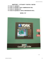
MODEL YST
CENTRIFUGAL LIQUID CHILLERS
RENEWAL PARTS
Supersedes: 160.67-RP2 (1004)
CONTROLS AND INSTRUMENTATION
MODEL YST
Steam-Turbine Drive Centrifugal
Liquid Chiller
Form: 160.67-RP2 (507)
FORM 160.67-RP2 (507)
IMPORTANT!
Read BEFORE PROCEEDING!
GENERAL SAFETY GUIDELINES
The components specified in this document are parts
of a relatively complicated apparatus. During installation, operation, maintenance or service, individuals
may be exposed to certain components or conditions
including, but not limited to: refrigerants, oils, materials under pressure, rotating components, and both high
and low voltage. Each of these items has the potential,
if misused or handled improperly, to cause bodily injury or death. It is the obligation and responsibility of
operating/service personnel to identify and recognize
these inherent hazards, protect themselves, and proceed
safely in completing their tasks. Failure to comply with
any of these requirements could result in serious damage
to the equipment and the property in which it is situated,
as well as severe personal injury or death to themselves
and people at the site.
This document is intended for use by owner-authorized
operating/service personnel. It is expected that this individual possesses independent training that will enable
them to perform their assigned tasks properly and safely.
It is essential that, prior to performing any task on this
equipment, this individual shall have read and understood any referenced materials. This individual shall
also be familiar with and comply with all applicable
governmental standards and regulations pertaining to
the task in question.
External wiring, unless specified as an optional connection in the manufacturer’s product
line, is NOT to be connected inside the micro panel cabinet. Devices such as relays, switches,
transducers and controls may NOT be installed inside the micro panel. NO external wiring
is allowed to be run through the micro panel. All wiring must be in accordance with YORK’s
published specifications and must be performed ONLY by qualified YORK personnel. YORK
will not be responsible for damages/problems resulting from improper connections to the
controls or application of improper control signals. Failure to follow this will void the
manufacturer’s warranty and cause serious damage to property or injury to persons.
REFERENCE INSTRUCTIONS
DESCRIPTION
2
FORM NO.
INSTALLATION
160.67-N1
OPTIVIEW CONTROL CENTER - OPERATION MANUAL
160.67-O1
OPTIVIEW CONTROL CENTER - SERVICE INSTRUCTIONS
160-67-M1
WIRING DIAGRAM – MODEL YST (STYLE F)
160.67-PW1
WIRING DIAGRAM – MODEL YST (STYLE F) AUTO START
160.67-PW3
LOGIC DIAGRAM - MODEL YST (STYLE F)
160.67-M2
RENEWAL PARTS – UNIT
160.67-RP1
ELECTRICAL CONNECTORS - MODEL YST
160.67-RP3
JOHNSON CONTROLS
FORM 160.67-RP2 (507)
CHANGEABILITY OF THIS
DOCUMENT
In complying with YORK’s policy for continuous product improvement, the information contained in this document is subject to change without notice. While YORK makes no commitment to update or provide current
information automatically to the manual owner, that information, if applicable, can be obtained by contacting
the nearest YORK Service office.
It is the responsibility of operating/service personnel as to the applicability of these documents to the equipment in
question. If there is any question in the mind of operating/service personnel as to the applicability of these documents, then, prior to working on the equipment, they should verify with the owner whether the equipment has been
modified and if current literature is available.
JOHNSON CONTROLS
3
FORM 160.67-RP2 (507)
TABLE OF CONTENTS
SECTION 1 - OPTIVIEW CONTROL CENTER ......... 5 SECTION 4 - UNIT MOUNTED DEVICES .................... 23
TABLE 1 - CONTROL CENTER COMPONENTS .......... 6
FIG. 1 - INSIDE OF OPTIVIEW™ CONTROL PANELNEMA 1 ......................................................... 8
FIG. 2 - FRONT VIEW OF DOOR-NEMA 1................. 9
FIG. 3 - INSIDE OF DOOR AND DISPLAY- NEMA 1 10
FIG. 4 - INSIDE OF OPTIVIEW™ CONTROL PANELNEMA 4/12 ....................................................11
FIG. 5 - FRONT VIEW OF DOOR-NEMA 4/12.......... 12
FIG. 6 - INSIDE OF DOOR AND DISPLAY- NEMA 4/12
..................................................................... 13
TABLE 11 - UNIT MOUNTED SENSORS AND CONTROL
DEVICES . . . . . . . . . . . . . . . . . . . . . . . . . . 23
FIG. 12 - CHILLER UNIT MOUNTED DEVICES . . . . 25
FIG. 12A - CHILLER UNIT MOUNTED DEVICES . . . 26
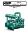
FIG. 13 - STEAM CONDENSER MOUNTED DEVICES
. . . . . . . . . . . . . . . . . . . . . . . . . . . . . . . . . . 27
FIG. 14A - "J4"/"J5" COMPRESSORS . . . . . . . . . . . 28
FIG. 14B - "J1"/"J2"/"U" COMPRESSORS . . . . . . . . 29
FIG. 15 - "H"/"P" COMPRESSOR . . . . . . . . . . . . . . . 30
SECTION 2 - POWER PANEL ................................. 14
TABLE 2 - POWER PANEL COMMON PARTS............ 14
TABLE 3 - POWER PANEL VARIABLE PARTS (R134a)
KG TURBINE PACKAGE ........................... 15
TABLE 4 - POWER PANEL VARIABLE PARTS (R134a)
KD TURBINE PACKAGE ........................... 16
TABLE 5 - POWER PANEL VARIABLE PARTS (R134a)
KG TURBINE PACKAGE ........................... 17
TABLE 6 - POWER PANEL VARIABLE PARTS (R134a)
KD TURBINE PACKAGE ........................... 18
FIG. 7 - FRONT VIEW OF POWER PANEL DOOR ... 18
FIG. 8 - INSIDE OF POWER PANEL ......................... 19
TABLE 7 - MOTOR PROTECTOR SETPOINT CHART
.................................................................... 19
SECTION 3 - TURBINE BOX................................... 18
TABLE 8 - TURBINE BOX COMMON PARTS ............. 20
TABLE 9 - TURBINE BOX VARIABLE PARTS ............. 20
FIG. 9 - INSIDE OF MANUAL START TURBINE BOX
..................................................................... 21
FIG. 10 - INSIDE OF AUTO START TURBINE BOX . 21
TABLE 10 - PARTS FOR TURBINE BOX W/ OPTIONAL
TURBINE AND COMPRESSOR VIBRATION
TRANSMITTERS ( SEE FIG.11) .............. 22
FIG. 11 - INSIDE OF TURBINE BOX W/ OPTIONAL
TURBINE AND COMPRESSOR VIBRATION
TRANSMITTERS ...................................... 22
4
FIG. 15A - PRV POSITION KIT . . . . . . . . . . . . . . . . . 31
FIG. 16 - KG TURBINE OIL COOLER WATER PIPING
. . . . . . . . . . . . . . . . . . . . . . . . . . . . . . . . . 31
FIG. 17 - KD TURBINE . . . . . . . . . . . . . . . . . . . . . . . 32
FIG. 17A - KG TURBINE . . . . . . . . . . . . . . . . . . . . . . 33
FIG. 18 - KD TURBINE SHAFT END BEARING . . . . 34
FIG. 18A - KG TURBINE - SHAFT END BEARING
. . . . . . . . . . . . . . . . . . . . . . . . . . . . . . . . . 34
FIG. 19 - KD TURBINE - GOVERNOR END BEARING
. . . . . . . . . . . . . . . . . . . . . . . . . . . . . . . . . . 35
FIG. 19A - KG TURBINE - GOVERNOR END BEARING
. . . . . . . . . . . . . . . . . . . . . . . . . . . . . . . . . . 35
FIG. 20 - TURBINE AUTO START SOLENOID VALVES
. . . . . . . . . . . . . . . . . . . . . . . . . . . . . . . . . . 36
FIG. 21 - STEAM CONDENSER HOTWELL LEVEL
TRANSMITTER AND SWITCHES . . . . . . 37
FIG. 22 - OPTIONAL TURBINE GAUGE BOARD . . . 38
JOHNSON CONTROLS
FORM 160.67-RP2 (507)
SECTION 1 - OPTIVIEW™ CONTROL CENTER
377-12421-101 (NEMA 1)
377-12421-102 (NEMA 1 WITH COMPRESSOR VGD)
377-15243-101 (NEMA 4/12)
377-15243-102 (NEMA 4/12 WITH COMPRESSOR VGD)
MODEL YST
LD10097
JOHNSON CONTROLS
5
FORM 160.67-RP2 (507)
TABLE 1 – CONTROL CENTER COMPONENTS
CONTROL CENTER COMPONENTS
ITEM
DESCRIPTION
1
Analog Input/Output Board
2
Kit, Digital Input/Output Board
FIG. NO.
QTY.
PART NO.
1/4
1
031-02472-000
1/4
1
371-04182-000
2A
AC Output Module
1/4
16
025-37818-000
2B
AC Input Module
1/4
8
025-37817-000
3
Terminal Block
1/4
1
025-38517-000
4
Input/Output Board
1/4
1
031-01743-002
5
Microprocessor Board (See Notes 2&4)
1/4
1
331-02430-607
1
025-34111-000
Includes Microprocessor Board 031-02430-004 and
Latest Version of Program Card 031-02501-001.
6
Power Supply
1/4
7
Transformer
1/4
1
025-39569-000
8
Switch, Keypad, OptiView™ Panel, NEMA 1
2
1
024-30993-000
8
Switch, Keypad, OptiView™ Panel, NEMA 4/12 and CE
5
1
024-30994-000
9
Fuse, 7A (See Note 3)
1/4
2
025-29905-000
9A
Fuse, 10A (See Note 3)
1/4
2
025-09662-000
9B
Fuse, 5A (See Note 3 )
1/4
2
025-14019-000
10
Fuse Holder (See Note 3)
1/4
2
025-13991-000
11
Fastener, Pawl Adjustable (NEMA 1)
3
1
021-17252-000
12
Switch, Rocker (NEMA 1)
3
1
024-23143-000
12A
Switch, Knob Operated (NEMA 4/12)
6
1
024-30931-000
12B
Contact, Block (NEMA 4/12)
6
2
024-30932-000
12C
Buss Bar (Gnd) (NEMA 4/12)
4
1
025-34122-000
13
Strip Neoprene
3/6
2.8 ft.
028-07533-000
14
Kit, Display (See Note 1)
Contains items, 26 thru 32
3/6
1
331-01771-000
15
Cover, Display
3/6
1
071-02264-346
16
Harness, Door Wiring (NEMA 1)
3/6
1
571-02772-281
17
Cable, Ribbon (NEMA 1)
3
1
031-01772-000
17
Cable, Ribbon (NEMA 4/12)
6
1
031-02015-000
18
Cable, Ribbon
1/4
1
031-01779-000
19
Terminal Block
1/4
1
025-38518-000
20
Fuse, Microfuse 5 amp (See Note 3)
1/4
1
025-34592-000
21
Mount, Anti-Vibration
1/4
22
Suppressor (See Note 3)
23
Fuse Holder
24
25
4
021-19191-000
6
031-00808-000
1/4
1
025-34565-000
Fuse, 5A (See Note 3)
1/4
3
025-15759-000
Fuse, 4A (See Note 3)
1/4
2
025-34566-000
26
Display, Color
3/6
1
(See Note 1)
27
Control, Display Interface Board
3/6
1
(See Note 1)
28
Inverter Circuit Board
3/6
1
(See Note 1)
29
Cable, Assembly Inverter
3/6
1
(See Note 1)
30
Adapter Plate
3/6
1
(See Note 1)
31
Plate, Mounting
3/6
1
(See Note 1)
32
Ribbon Cable, Display
3/6
1
(See Note 1)
33
IC, BRAM-U38 (32K x 8) (See Note 2)
1/4
1
031-02431-000
IC, BRAM-U38 (128K X 8) (See Note 3)
1/4
1
031-02565-000
33A
6
JOHNSON CONTROLS
FORM 160.67-RP2 (507)
TABLE 1 (CON'T) – CONTROL CENTER COMPONENTS
CONTROL CENTER COMPONENTS (CONT'D)
CABLE, VGD
ITEM
DESCRIPTION
34
EPROM, BIOS (U37) FPU Enabled
35
VGD Board
36
Cable, VGD
FIG. NO.
QTY.
PART NO.
1/4
1
031-02429-002
1/4
1
031-02418-000
1/4
1
571-04118-401
NOTES:
1. The replacement Liquid Crystal Display supplied by YORK might not be by the same manufacturer as the original Display. Each Display requires a specific
Display Interface Board (Item 31), Inverter Circuit Board (Item 32), and Display Ribbon Cable (Item 36). Therefore, the Color Display is not available
separately. Service replacement Displays or supporting components must not be arbitrarily selected! Non-compatibility of components will result
in incorrect operation! To assure compatible supporting components, the Display is supplied as a kit (331-01771-000), which contains a replacement
Display and all compatible supporting components on a mounting plate. For future reference, a label attached to the side of the mounting plate (Fig. 3/6)
lists the YORK part numbers of these compatible components and the required configuration of the Microboard Program Jumpers. These Program Jumpers
must be configured for this Display by a qualified Service Technician following instructions in YORK Service manual 160.67-M1. The contents of the kit
are as follows:
a. Color Display
f. Mounting Plate
b. Appropriate Display Interface Board (Item 48)
g. Appropriate Display Cable Ribbon
c. Inverter Circuit Board
h. All Mounting Hardware
d. Inverter Cable Assembly
j. Installation Instructions
e. Adapter Plate
2. Replacement Microboards maybe supplied with either of the part numbers shown in items 33 and 33A BRAM (U38). The BRAM from the defective board
can be transferred to the replacement board, if desired to avoid re-programming of Setpoints. Return all unused Devices with Warranty return boards.
3. Spare Supressors and Fuses are shipped in cloth bag. They are applied at all Coils connected to the I/O Boards. Item 9B and additional fuseholder is required
only on chillers with J7 compressors.
4. Program Card version analysis:
C.OPT.nn.nn.nnn
Language Package Revision Level (00,01,etc)
Language Package* (0=English only, 1=NEMA 1-4, 2=CE, 3=NEMA/CE)
Controls Revision Level (00,01,etc)
Chiller Type (OptiView Control Center, 12=YST)
OptiView Control Center
Commercial Chiller
*1 = Supplied in new NEMA 1-4 OptiView Control Centers.
2 = Supplied in new CE (European Community) OptiView Control Centers.
JOHNSON CONTROLS
7
FORM 160.67-RP2 (507)
FIG. 1 – INSIDE OF OPTIVIEW™ CONTROL PANEL-NEMA 1
8
LD12627
JOHNSON CONTROLS
FORM 160.67-RP2 (507)
FIG. 2 – FRONT VIEW OF DOOR-NEMA 1
JOHNSON CONTROLS
LD12628
9
FORM 160.67-RP2 (507)
LABEL LISTING DISPLAY
SUPPORTING COMPONENT
PART NUMBERS
FIG. 3 – INSIDE OF DOOR AND DISPLAY- NEMA 1
10
LD12629
JOHNSON CONTROLS
FORM 160.67-RP2 (507)
FIG. 4 – INSIDE OF OPTIVIEW™ CONTROL PANEL-NEMA 4/12
JOHNSON CONTROLS
LD12630
11
FORM 160.67-RP2 (507)
8
FIG. 5 – FRONT VIEW OF DOOR-NEMA 4/12
12
LD10106
JOHNSON CONTROLS
FORM 160.67-RP2 (507)
LABEL LISTING DISPLAY
SUPPORTING COMPONENT
PART NUMBERS
FIG. 6 – INSIDE OF DOOR AND DISPLAY-NEMA 4/12
JOHNSON CONTROLS
LD12631
13
FORM 160.67-RP2 (507)
SECTION 2 - POWER PANEL
TABLE 2 – POWER PANEL COMMON PARTS
ITEM
1
2
3
4
5
6
7
8
9
10
11
12
13
14
15
16
17
18
19
20
21
22
23
24
25
26
27
28
29
30
31
32
33
34
35
36
37
14
DESCRIPTION
Box, Elec. Power Panel
Rail, Mounting 35mm x 7.5mm
O-ring, Seal
Switch, HPCO
Clamp, DIN Rail
Heatsink
Terminal Block
End Cover
Sealing Ring, 1/2
Label, Ground
Label ,Warning German
Label, Warning
Zack Strip
Compound, Heat Conductive
Locknut, Conduit, 1/2
Contactor (M1)
Screw, Tapping #6-32unc
Adapter, Bulkhead
Lockwasher, Th External 1/4
Horn, 120VAC
Fuseblock, 1 Pole, 600v
Fuseblock, 2 Pole, 600v
Fuseblock, 3 Pole, 600v
Kit, Door Mounting, Disconnect
Terminal, Ground
Nut/Washer Assy #10-24
Screw, Mach. Pan Head, 1-1/4-20 x 1/2
Fuse, Cartridge Type, 20 Amp (FU7)
Partition Plate
Jumper
Strap, Ground
Nut, Kep #8-32
Bus, Bar Terminal Block
Bracket, Inductor, Mounting
Screw, Mach. Rd. Hd. #8-32 x 1-3/4 LG.
Nut, Hex Mach. Screw #8-32
Screw, Hex 1/4-20 x 5/8 LG.
YORK P/N
377-14043-311
025-29167-000
028-12961-021
025-37890-200
025-29189-000
071-02766-301
025-37649-000
025-34440-000
025-09613-000
030-15990-000
035-11929-000
035-03908-000
025-36911-000
013-02997-000
025-05701-000
024-25522-000
021-19152-000
023-20859-000
021-02507-000
025-22378-000
025-37862-000
025-37864-000
025-37863-000
024-34016-000
025-33267-000
021-18024-000
021-01853-000
025-35908-000
025-35620-000
025-37650-000
525-32508-000
021-17664-000
029-23434-000
377-14043-315
021-17386-000
021-08661-000
021-09224-000
QTY.
1
1
1
1
4
1
6
1
1
1
1
1
1
.01
1
1
2
1
8
1
1
1
1
1
1
8
8
1
1
1
1
2
1
1
2
2
4
JOHNSON CONTROLS
FORM 160.67-RP2 (507)
TABLE 3 – POWER PANEL VARIABLE PARTS (R134a) KG TURBINE PACKAGE
POWER PANEL VARIABLE PARTS (R-134a) KG TURBINE PACKAGE
Standard: 1 Hotwell Pump, 1 Vacuum Pump Optional: 2 Hotwell Pumps, 2 Vacuum Pumps
280 VAC
460 VAC
280 VAC
460 VAC
377-14043-101
377-14043-102
377-14043-103
377-14043-104
ITEM
Part #
QTY.
Part #
QTY.
Part #
QTY.
Part #
QTY.
100
Common Parts
DESCRIPTION
377-14043-010
1
377-14043-010
1
377-14043-010
1
377-14043-010
1
101
Variable Speed Oil Pump Drive
024-30468-001
1
024-30468-002
1
024-30468-001
1
024-30468-002
1
102
Fuse, Cartridge (FU8, FU9)
025-35907-000
2
025-35902-000
2
025-35907-000
2
025-35902-000
1
103
Motor, Starter Manual Bus Bar
024-27270-000
2
024-27270-000
2
024-34490-000
2
024-34490-000
2
104
Contactor (M2)
-
-
-
-
-
-
-
-
105
Contactor (M3)
024-25526-000
1
024-25522-000
1
024-25526-000
1
024-25522-000
1
106
Contactor (M4)
-
-
-
-
024-25526-000
1
024-25521-000
1
107
Contactor (M5)
024-25584-000
1
024-25521-000
1
024-25584-000
1
024-25521-000
1
108
Contactor (M6)
-
-
-
-
024-25584-000
1
024-25521-000
1
109
Motor Protector (OL1)
024-27281-000
1
024-27280-000
1
024-27281-000
1
024-27280-000
1
110
Motor Protector (OL2)
-
-
-
-
-
-
-
-
111
Motor Protector (OL3)
024-27283-000
1
024-27281-000
1
204-27283-000
1
024-27281-000
1
112
Motor Protector (OL4)
-
-
-
-
024-27283-000
1
024-27281-000
1
113
Motor Protector (OL5)
024-27284-000
1
024-27268-000
1
024-27284-000
1
024-27268-000
1
114
Motor Protector (OL6)
-
-
-
-
024-27284-000
1
024-27268-000
1
115
Inductor
025-37860-000
1
025-37861-000
1
025-37860-000
1
025-37861-000
1
116
Switch, Disconnect
024-34871-000
1
024-34870-000
1
024-34871-000
1
024-34870-000
1
117
Fuse, Cart., (FU10, FU11, FU12)
025-35905-000
3
025-35901-000
3
025-35905-000
3
025-35901-000
3
118
Main Harness
377-14043-201
1
377-14043-203
1
377-14043-205
4
377-14043-207
1
119
Kit Transformer
375-48198-001
1
375-48198-003
1
375-48198-001
1
375-48198-003
1
JOHNSON CONTROLS
15
FORM 160.67-RP2 (507)
TABLE 4 – POWER PANEL VARIABLE PARTS (R134a) KD TURBINE PACKAGE
POWER PANEL VARIABLE PARTS (R-134a) KD TURBINE PACKAGE
Standard: 1 Hotwell Pump, 1 Vacuum Pump Optional: 2 Hotwell Pumps, 2 Vacuum Pumps
280 VAC
460 VAC
280 VAC
460 VAC
377-14043-111
377-14043-112
377-14043-113
377-14043-114
ITEM
DESCRIPTION
Part #
QTY.
Part #
QTY.
Part #
QTY.
Part #
QTY.
100
Common Parts
377-14043-010
1
377-14043-010
1
377-14043-010
1
377-14043-010
1
101
Variable Speed Oil Pump Drive
024-30468-001
1
024-30468-002
1
024-30468-001
1
024-30468-002
1
102
Fuse, Cartridge (FU8, FU9)
025-35907-000
2
025-35902-000
2
025-35907-000
2
025-35902-000
2
103
Motor, Starter Manual Bus Bar
024-34490-000
2
024-34490-000
2
024-34490-000
2
024-34490-000
2
104
Contactor (M2)
024-25522-000
1
024-25522-000
1
024-25522-000
1
024-25522-000
1
105
Contactor (M3)
024-25526-000
1
024-25522-000
1
024-25526-000
1
024-25522-000
1
106
Contactor (M4)
-
-
-
-
024-25526-000
1
024-25522-000
1
107
Contactor (M5)
024-25584-000
1
024-25521-000
1
024-25584-000
1
024-25521-000
1
108
Contactor (M6)
-
-
-
-
024-25584-000
1
024-25521-000
1
109
Motor Protector (OL1)
024-27281-000
1
024-27280-000
1
024-27281-000
1
024-27280-000
1
110
Motor Protector (OL2)
024-27280-000
1
024-27278-000
1
024-27280-000
1
024-27278-000
1
111
Motor Protector (OL3)
024-27283-000
1
024-27281-000
1
204-27283-000
1
024-27281-000
1
112
Motor Protector (OL4)
-
-
-
-
024-27283-000
1
024-27281-000
1
113
Motor Protector (OL5)
024-27284-000
1
024-27268-000
1
024-27284-000
1
024-27268-000
1
114
Motor Protector (OL6)
-
-
-
-
024-27284-000
1
024-27268-000
1
115
Inductor
025-37860-000
1
025-37861-000
1
025-37860-000
1
025-37861-000
1
116
Switch, Disconnect
024-34871-000
1
024-34870-000
1
024-34871-000
1
024-34870-000
1
117
Fuse, Cart., (FU10, FU11, FU12)
025-35905-000
3
025-35901-000
3
025-35905-000
3
025-35901-000
3
118
Main Harness
377-14043-209
1
377-14043-211
1
377-14043-213
4
377-14043-215
1
119
Kit Transformer
375-48198-001
1
375-48198-003
1
375-48198-001
1
375-48198-003
1
16
JOHNSON CONTROLS
FORM 160.67-RP2 (507)
TABLE 5 – POWER PANEL VARIABLE PARTS (R134a) KG TURBINE PACKAGE
POWER PANEL VARIABLE PARTS (R-134a) KG TURBINE PACKAGE
Standard: 1 Hotwell Pump, 1 Vacuum Pump Optional: 2 Hotwell Pumps, 2 Vacuum Pumps
280 VAC
460 VAC
280 VAC
460 VAC
377-14043-121
377-14043-122
377-14043-123
377-14043-124
ITEM
Part #
QTY.
Part #
QTY.
Part #
QTY.
Part #
QTY.
100
Common Parts
DESCRIPTION
377-14043-010
1
377-14043-010
1
377-14043-010
1
377-14043-010
1
101
Variable Speed Oil Pump Drive
024-30468-001
1
024-30468-002
1
024-30468-001
1
024-30468-002
1
102
Fuse, Cartridge (FU8, FU9)
025-35907-000
2
025-35902-000
2
025-35907-000
2
025-35902-000
1
103
Motor, Starter Manual Bus Bar
024-34490-000
1
024-34490-000
1
024-34490-000
2
024-34490-000
2
104
Contactor (M2)
024-25522-000
1
024-25522-000
1
024-25522-000
1
024-25522-000
1
105
Contactor (M3)
024-25526-000
1
024-25522-000
1
024-25526-000
1
024-25522-000
1
106
Contactor (M4)
-
-
-
-
024-25526-000
1
024-25522-000
1
107
Contactor (M5)
-
-
-
-
024-25584-000
1
024-25521-000
1
108
Contactor (M6)
-
-
-
-
-
-
-
-
109
Motor Protector (OL1)
024-27281-000
1
024-27280-000
1
024-27281-000
1
024-27280-000
1
110
Motor Protector (OL2)
-
-
-
-
-
-
-
-
111
Motor Protector (OL3)
024-27283-000
1
024-27281-000
1
204-27283-000
1
024-27281-000
1
112
Motor Protector (OL4)
-
-
-
-
024-27283-000
1
024-27281-000
1
113
Motor Protector (OL5)
-
-
-
-
024-27284-000
1
024-27268-000
1
114
Motor Protector (OL6)
-
-
-
-
-
-
-
-
115
Inductor
025-37860-000
1
025-37861-000
1
025-37860-000
1
025-37861-000
1
116
Switch, Disconnect
024-34871-000
1
024-34870-000
1
024-34871-000
1
024-34870-000
1
117
Fuse, Cart., (FU10, FU11, FU12)
025-35905-000
3
025-35901-000
3
025-35905-000
3
025-35901-000
3
118
Main Harness
377-14043-217
1
377-14043-219
1
377-14043-221
4
377-14043-223
1
119
Kit Transformer
375-48198-001
1
375-48198-003
1
375-48198-001
1
375-48198-003
1
JOHNSON CONTROLS
17
FORM 160.67-RP2 (507)
TABLE 6 – POWER PANEL VARIABLE PARTS (R134a) KD TURBINE PACKAGE
POWER PANEL VARIABLE PARTS (R-134a) KD TURBINE PACKAGE
Standard: 1 Hotwell Pump, 1 Vacuum Pump Optional: 2 Hotwell Pumps, 2 Vacuum Pumps
280 VAC
460 VAC
280 VAC
460 VAC
377-14043-121
377-14043-122
377-14043-123
377-14043-124
ITEM
Part #
QTY.
Part #
QTY.
Part #
QTY.
Part #
QTY.
100
Common Parts
DESCRIPTION
377-14043-010
1
377-14043-010
1
377-14043-010
1
377-14043-010
1
101
Variable Speed Oil Pump Drive
024-30468-001
1
024-30468-002
1
024-30468-001
1
024-30468-002
1
102
Fuse, Cartridge (FU8, FU9)
025-35907-000
2
025-35902-000
2
025-35907-000
2
025-35902-000
2
103
Motor, Starter Manual Bus Bar
024-27270-000
1
024-27270-000
1
024-34490-000
1
024-34490-000
1
104
Contactor (M2)
-
-
-
-
-
-
-
-
105
Contactor (M3)
024-25526-000
1
024-25522-000
1
024-25526-000
1
024-25522-000
1
106
Contactor (M4)
-
-
-
-
024-25526-000
1
024-25522-000
1
107
Contactor (M5)
-
-
-
-
024-25584-000
1
024-25521-000
1
108
Contactor (M6)
-
-
-
-
-
-
-
-
109
Motor Protector (OL1)
024-27281-000
1
024-27280-000
1
024-27281-000
1
024-27280-000
1
110
Motor Protector (OL2)
-
-
-
-
-
-
-
-
111
Motor Protector (OL3)
024-27283-000
1
024-27281-000
1
204-27283-000
1
024-27281-000
1
112
Motor Protector (OL4)
-
-
-
-
024-27283-000
1
024-27281-000
1
113
Motor Protector (OL5)
-
-
-
-
024-27284-000
1
024-27268-000
1
114
Motor Protector (OL6)
-
-
-
-
024-27284-000
1
024-27268-000
1
115
Inductor
025-37860-000
1
025-37861-000
1
025-37860-000
1
025-37861-000
1
116
Switch, Disconnect
024-34871-000
1
024-34870-000
1
024-34871-000
1
024-34870-000
1
117
Fuse, Cart., (FU10, FU11, FU12)
025-35905-000
3
025-35901-000
3
025-35905-000
3
025-35901-000
3
118
Main Harness
377-14043-217
1
377-14043-219
1
377-14043-221
4
377-14043-223
1
119
Kit Transformer
375-48198-001
1
375-48198-003
1
375-48198-001
1
375-48198-003
1
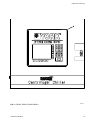
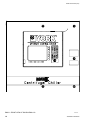
(SEE NOTE 3)
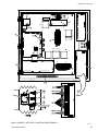
FIG. 7 – FRONT VIEW OF POWER PANEL DOOR
18
LD10133
JOHNSON CONTROLS
FORM 160.67-RP2 (507)
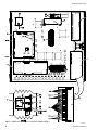
(SEE NOTE 4)
LD10132
LAYOUT SHOWN FOR 377-14043-114
(SEE NOTE 2)
FIG. 8 – INSIDE OF POWER PANEL
NOTES:
1. USING ROLLER (HUNT SPEEDBALL BRAYER NO.49P OR EQUIV.) APPLY HEAT CONDUCTIVE COMPOUND (ITEM14) TO THE
BOTTOM SURFACE OF THE DRIVE (ITEM 101). BEFORE ATTACHING TO THE HEATSINK.
2. AUX. TURBINE OIL PUMP CONTACTOR (M2) AND MOTOR PROTECTOR (OL2) ARE SUPPLIED ON CHILLERS WITH KD
TURBINE PACKAGES ONLY. HOTWELL PUMP AND VACUUM PUMP CONTACTORS (M4) AND (M6) AND MOTOR PROTECTORS
(OL4 & OL6) ARE SUPPLIED ONLY ON CHILLERS WITH DUAL PUMPS.
3. MODIFY OPERATING SHAFT BY CUTTING THE LENGTH TO SUIT AT ASSEMBLY.
4. SET ALL OVERLOADS PER TABLE 7.
TABLE 7 – MOTOR PROTECTOR SETPOINT CHART
208VAC
101, 103, 111, & 113 ONLY
DESCRIPTION
SETPOINT
OL1
8.33 AMPS
460VAC
102, 104, 112, & 114 ONLY
DESCRIPTION
SETPOINT
OL1
3.8 AMPS
OL2
3.1 AMPS
OL2
1.4 AMPS
OL3
16.8 AMPS
OL3
7.6 AMPS
OL4
16.8 AMPS
OL4
7.6 AMPS
OL5
24.3 AMPS
OL5
11.0 AMPS
OL6
24.3 AMPS
OL6
11.0 AMPS
JOHNSON CONTROLS
19
FORM 160.67-RP2 (507)
SECTION 3 - TURBINE BOX
TABLE 8 – TURBINE BOX COMMON PARTS
ITEM
1
2
3
4
5
6
DESCRIPTION
Switch, Speed
Converter, Frequency to Analog
Rail, Mounting, 35mm x 7.5mm
Connr, Cable Str. 1/2
Transmitter, Temp.
Transmitter, Temp.
PART #
025-38776-000
025-38775-000
025-29167-000
025-08301-000
025-39696-000
025-39696-001
QTY.
1
2
1
2
2
1
TABLE 9 – TURBINE BOX VARIABLE PARTS
ITEM
100
101
102
103
104
105
106
107
ITEM
100
101
102
103
104
105
106
107
20
DESCRIPTION
Common Parts
Box, Electrical
Panel , Mounting
Transmitter, Vibration
Clamp, DIN Rail
Locknut, 1/2 NPT
Fitting, 1/2 NPT
Transmitter, Temp.
377-14057-101
Manual Start (KD) FIG. 9
PART #
QTY.
377-14057-000
1
028-39567-000
1
025-39657-001
1
025-34439-000
2
025-39696-000
1
377-14057-102
Auto Start (KD) FIG. 10
PART #
QTY.
377-14057-000
1
025-39568-000
1
025-39568-001
1
025-38782-000
4
025-34439-000
4
025-34090-000
4
025-28720-000
4
025-39696-000
1
DESCRIPTION
Common Parts
Box, Electrical
Panel , Mounting
Transmitter, Vibration
Clamp, DIN Rail
Locknut, 1/2 NPT
Fitting, 1/2 NPT
Transmitter, Temp.
377-14057-103
Manual Start (KG) FIG. 9
PART #
QTY.
377-14057-000
1
028-39567-000
1
025-39657-001
1
025-34439-000
2
-
377-14057-104
Auto Start (KG) FIG. 10
PART #
QTY.
377-14057-000
1
025-39568-000
1
025-39568-001
1
025-38782-000
4
025-34439-000
4
025-34090-000
4
025-28720-000
4
-
JOHNSON CONTROLS
FORM 160.67-RP2 (507)
101
102
3
107
}
5
5
6
4
2
2
1
4
SEE
NOTES
1&2
104
LAYOUT SHOWN FOR MANUAL START 377-14057-101
LD10136
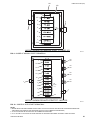
FIG. 9 – INSIDE OF MANUAL START TURBINE BOX
105
106
3
103
105
106
103
103
105
106
103
107
5
4
5
6
2
2
1
}
105
106
SEE
NOTES
1&2
4
104
LAYOUT SHOWN FOR AUTO START 377-14057-102
LD10134
FIG. 10 – INSIDE OF AUTO START TURBINE BOX
NOTES:
1. BEFORE INSTALLING REPLACEMENT PARTS VERIFY THAT THE DIP SWITCH SETTINGS AND CALIBRATED RANGES ARE
THE SAME AS THE ORIGINAL PART. (SEE FORM 160.67-M1 FOR CALIBRATION PROCEDURES)
2. TT-160 IS SUPPLIED ON CHILLERS WITH KD TURBINE PACKAGES ONLY.
3. VT-161 H/V AND VT-162 H/V MAY ALSO BE SUPPLIED AS OPTIONAL EQUIPTMENT ON MANUAL START CHILLERS.
JOHNSON CONTROLS
21
FORM 160.67-RP2 (507)
7
8
6
5
5
5
9
9
9
9
10
11
(SEE NOTES 1& 2)
12
1
2
12
2
4
(SEE NOTES 1& 2)
LD10138
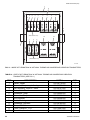
FIG. 11 – INSIDE OF TURBINE BOX W/ OPTIONAL TURBINE AND COMPRESSOR VIBRATION TRANSMITTERS
TABLE 10 – PARTS FOR TURBINE BOX W/ OPTIONAL TURBINE AND COMPRESSOR VIBRATION
TRANSMITTERS ( SEE FIG.11 )
ITEM
1
2
3
4
5
6
7
8
9
10
11
12
22
DESCRIPTION
Switch, Speed
Converter, Frequency to Analog
Rail, Mounting, 35mm x 7.5mm
Connr, Cable Str. 1
Transmitter, Temp.
Transmitter, Temp.
Box, Electrical
Panel ,Moutning
Transmitter, Vibration
Clamp, DIN Rail
Connr, Cable Str. 1-1/4
Transmitter, Acceleration
PART #
025-38776-000
025-38775-000
025-29167-000
025-12282-000
025-39696-000
025-39696-001
025-39568-000
025-39568-000
025-38782-000
025-34439-000
025-15981-000
025-39941-000
QTY.
1
2
1
1
3
1
1
1
4
6
1
2
JOHNSON CONTROLS
FORM 160.67-RP2 (507)
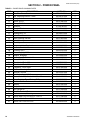
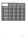
SECTION 4 - UNIT MOUNTED DEVICES
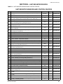
TABLE 11 – UNIT MOUNTED SENSORS AND CONTROL DEVICES
UNIT MOUNTED SENSORS AND CONTROL DEVICES
ITEM
DESCRIPTION
FIG. NO.
QTY.
PART NO.
1
Transducer, Pressure-Condenser Refrigerant, Compressor High and
Low Oil
13/14/15
3
025-28678-006
2
Transducer, Pressure-Evaporator Refrigerant
12
1
025-28678-112
3
Transducer, Pressure-Compressor Stall-VGD Compressors only
(Some rewiring may be required. Refer to Form 160.67-M1)
13
1
025-40088-000
4
O-ring, Seal-for Pressure Transducers, items 1, 2, and 3
12/13/14/15
5
028-12961-002
5
Sensor, Temperature (Thermistor) - Chilled and Condenser Water Return and Leaving, Drop Leg Refrigerant Liquid
12/13
5
025-29964-000
6
Well, Thermo - For Chilled and Condenser Water Return and Leaving
Temperature Sensors
12
4
026-32328-000
7
Sensor, Temperature (Thermistor) - Evaporator Refrigerant Liquid
(3/4-16UNF-2A)
13
1
025-34159-000
8
Sensor, Temperature (Thermistor) - Compressor Oil and Refrigerant
Discharge (3/4-16UNF-2A)
13
2
025-33288-000
9
O-ring, Seal-for Temperature Sensors, for items 7 and 8
13
3
028-12961-004
10
Sensor, Level - Subcooler Liquid Refrigerant
13
1
025-35144-000
11
Gasket, Seal - for item 10
13
1
028-04836-000
12
Sensor, Flow - Chilled and Condenser Water
12
2
025-38145-001
13
Valve, Solenoid - Compressor Oil Return
13
1
025-35150-001
14
Valve, Solenoid - Compressor Liquid Injection ("J" Compressor Only)
13
1
025-35150-002
15
O-ring, Seal - for Solenoid Valves, items 13 and 14
13
4
028-12961-012
16
Valve Assembly, Ball - Compressor ("H" & "P" Compressors Only) and
Turbine Oil Cooler Water (See Note 1)
12/16
2
025-41560-003
17
Valve Assembly, Ball - Compressor Oil Cooler Water ("U" and "J" Compressors Only (See Note 1)
12
1
025-41560-005
18
Actuator, Electric - Hot Gas Bypass Valve
12
1
025-38180-000
19
Actuator, Electric - Subcooler Level Control Valve Actuator
13
1
025-40648-001
20
Actuator, Electric - Oil Cooler Water Ball Valve
12/16
2
025-41561-000
21
Probe, Proximity (Sensor) - Compressor Thrust ("U" and "J" Compressors Only) (See Note 2)
14
1
025-40496-001
21A
Probe, Proximity (Electronics Module) (See Note 2)
14
1
025-40648-002
21B
Probe, Proximity (Connecting Cable) (See Note 2)
14
1
025-40648-003
22
O-ring, Seal - for Compressor Thrust Probe, item 21
14
1
028-12209-000
23
Switch, Pressure - Compressor Thrust ("H" & "P" Compressors Only)
24
Actuator, with Pre-wired Plug - Compressor PRV and VGD
25
Actuator, with Pre-wired Plug - Compressor PRV ("H" Compressor Only)
26
27
*28
Kit, Accelerometer - Compressor Horizontal and Vertical (includes cable
and mounting screw
29
15
1
025-40136-000
14A/14B
2
375-49340-103
15
1
375-49340-101
Kit, PRV Position (complete assembly)
15A
1
371-02012-001
Pot, 2500Ohms (part of item 26)
15A
1
025-32570-000
14/14A/15
2
025-39942-000
Transmitter, Pressure - Steam Exhaust (Fixed Range - 14.7 to 30
PSIG)
17
1
025-38549-000
30
Transmitter, Pressure - Turbine Supply Oil (Fixed Range - 0 to 30
PSIG)
17
1
025-38550-000
31
Transmitter, Pressure - Steam Inlet (Fixed range - 0 to 300 PSIG)
17
1
025-38551-000
32
Transmitter, Pressure - Turbine First Stage (Fixed Range - 0 to 100
PSIG) - Condensing Turbine
17
1
025-39542-000
JOHNSON CONTROLS
23
FORM 160.67-RP2 (507)
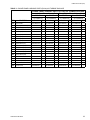
TABLE 11 (CON'T) – UNIT MOUNTED SENSORS AND CONTROL DEVICES
ITEM
DESCRIPTION
33
Transmitter, Pressure - Turbine First Stage (Fixed Range - 0 to 150
PSIG) - Non-Condensing Turbine
FIG. NO.
QTY.
PART NO.
17
1
025-39680-000
34
Magnetic Pick-up - for Speed Switch (5/8 - 18 UNF - 2A)
18/19
1
025-35232-000
35
Cable, Magnetic Pick-up - for item 34
18/19
1
025-35233-000
36
Magnetic Pick-up for Analog Speed Signals (3/4 - 20 UNEF-2A)
18/19
2
025-39543-000
37
Cable, Magnetic Pick-up - for item 36
18/19
2
025-39544-000
38
Sensor, Temperature (100 Ohm Platinum RTD/DIN 43760) - Turbine
Shaft End and Governor End Bearings
18/19
2
025-38784-000
39
Holder, Fluid Seal, Spring Loaded - for Turbine Bearing Temperature
Sensors item 38
18/19
2
025-38785-000
40
Sensor, Temperature (100 Ohm Platinum RTD/DIN 43760) - Turbine
Supply Oil - KD Turbine Only
17
1
025-36755-000
41
Sensor, Temperature (100 Ohm Platinum RTD/DIN 43760) Steam Inlet
(includes Thermowell)
17
1
025-39545-000
42
Transducer, Current to Pneumatic - Turbine Governor Valve
17
1
025-40246-000
43
Valve, Solenoid - Turbine Vacuum Breaker
17
1
025-40282-000
44
Valve, Solenoid - Turbine Trip
17
1
025-40285-000
45
Switch, SPDT - Trip Valve Limit Switch (Replacement switch module only)
17
1
025-40286-000
46
Probe, Vibration, 8 MM - Turbine Shaft End and Governor End Horizontal and Vertical
18/19
4
025-38783-000
47
Cable, Turbine Vibration, 4.5 Meter Total Length - for item 46
18/19
4
025-39453-000
48
Valve, Solenoid
20
1
025-40283-000
49
Valve, Solenoid - Turbine Nozzle Valve Air Dump
20
2
025-40284-000
50
Transmitter, Level - Steam Condensor Hotwell
21
1
025-40247-000
51
Switch, Level - Steam Condensor Hotwell High and Low Level
21
2
025-40248-000
52
Transducer, Current to Pneumatic - Steam Condensor Level Control
13
1
025-40249-000
53
Valve, Solenoid - Vacuum Pump Sealing Water
13
1
025-40316-000
54
Switch, Flow - Vacuum Pump Sealing Water
13
1
024-35101-00
55
Tachometer
22
1
025-40250-000
56
Siphon - Used for all Steam Pressure Transmitters
30/31
3
026-35995-000
57
Valve, Ball - Used for all Pressure Transmitters
30/31
4
022-09299-000
*Indicates Optional Equipment
NOTES:
1. Chillers manufactured after June 2006 are supplied with an electrically actuated ball valve. In lieu of replacing the solenoid
valve on older chillers, it is recommended that the strainer be removed and the solenoid valve be replaced with an appropriate ball valve.
2. Chillers manufactured after June 2006 are supplied with the two-piece probe. The one-piece probe originally supplied on older
chillers will no longer be available for replacement. Refer to Form 160.67-M1, Section 13, for additional details on installing
the new probe.
24
JOHNSON CONTROLS
FORM 160.67-RP2 (507)
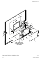
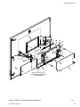
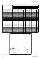
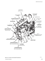
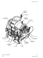
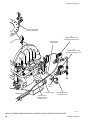
COMPRESSOR
( SEE FIG. 14 & 15)
STEAM TURBINE
(KD SHOWN)
(SEE FIG. 17)
STEAM CONDENSER
PACKAGE
GOVERNOR VALVE
2&4
EVAPORATOR REFRIGERANT
PRESSURE TRANSDUCER
TRIP VALVE LIMIT
SWITCH
18
HOT GAS BYPASS
VALVE ACTUATOR
VACUUM BREAKER
SOLENOID VALVE
16
TURBINE OIL
COOLING WATER
INLET VALVE
(SEE FIG. 16
FOR KG TURBINE )
12
CONDENSER WATER
FLOW SENSOR
5&6
LEAVING CONDENSER
WATER TEMPERATURE
SENSOR AND WELL
16 OR 17
COMPRESSOR OIL COOLING
WATER INLET VALVE
TURBINE
BOX
5&6
RETURN CONDENSER WATER
TEMPERATURE SENSOR AND WELL
5&6
RETURN CHILLED WATER
TEMPERATURE SENSOR AND
WELL (LOCATION MAY VARY)
CONTROL
CENTER
POWER
PANEL
PRV POSITION KIT
(SEE FIG. 14 &15)
EVAPORATOR
12
CHILLED WATER
FLOW SENSOR
(LOCATION MAY VARY)
5&6
LEAVING CHILLED WATER
TEMPERATURE SENSOR AND
WELL (LOCATION MAY VARY)
FIG. 12 - CHILLER UNIT MOUNTED DEVICES
JOHNSON CONTROLS
LD10175
25
FORM 160.67-RP2 (507)
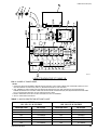
3&4
COMPRESSOR STALL
PRESSURE TRANSDUCER
8&9
COMPRESSOR
REFRIGERANT DISCHARGE
TEMPERATURE SENSOR
OIL FROM
TEMPERATURE CONTROL
VALVE
1&4
CONDENSER REFRIGERANT
PRESSURE TRANSDUCER
CONDENSER
7&9
EVAPORATOR REFRIGERANT
LIQUID TEMPERATURE SENSOR
TO POWER
PANEL
STOP VALVE
OIL EDUCTOR
BLOCK
13 & 15
COMPRESSOR OIL
RETURN SOLEOID
VALVE
DEHYDRATOR
1&3
COMPRESSOR LOW OIL
PRESSURE
TRANSDUCER
14 &15
COMPRESSOR LIQUID
INJECTION SOLENOID
( J COMPRESSOR ONLY)
SIGHT
GLASS
STOP VALVE
EVAPORATOR
19
SUBCOOLER LEVEL
CONTROL VALVE ACTUATOR
8&9
COMPRESSOR OIL
TEMPERATURE
SENSOR
10 & 11
SUBCOOLER LIQUID
REFRIGERANT LEVEL
SENSOR
5
DROP LEG
REFRIGERANT LIQUID
TEMPERATURE SENSOR
FIG. 12A - CHILLER UNIT MOUNTED INSTRUMENTS
26
LD10193
JOHNSON CONTROLS
FORM 160.67-RP2 (507)
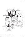
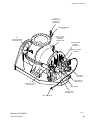
HOTWELL CONDENSATE PUMP #2
(OPTIONAL)
CONDENSATE
RECIRCULATION VALVE
CONDENSATE OVERBOARD
VALVE
ATMOSPHERIC RELIEF VALVE
52
HOTWELL LEVEL CONTROL
I/P TRANSDUCER
HOTWELL CONDENSATE LEVEL
INDICATOR / TRANSMITTER
(SEE FIG. 21)
LD10194
HOTWELL CONDENSATE PUMP #1
120/460 VAC. JUNCTION BOX
VACUUM PUMP #1
VACUUM PUMP #2
53
VACUUM PUMP #2
SEALING WATER
SOLENOID VALVE
54
VACUUM PUMP #2
SEALING WATER FLOW SWITCH
FIG. 13 - STEAM CONDENSER MOUNTED DEVICES
JOHNSON CONTROLS
LD10192
27
FORM 160.67-RP2 (507)
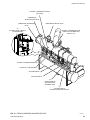
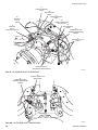
24
VGD ACTUATOR
8&9
COMPRESSOR DISCHARGE
TEMPERATURE SENSOR
PRV POSITION KIT
(SEE FIG. 15A FOR
INSTALLATION)
1&4
COMPRESSOR HIGH OIL
PRESSURE TRANSDUCER
LD10202
24
PRV ACTUATOR
28
ACCELEROMETER KIT
28
ACCELEROMETER KIT
22
COMPRESSOR THRUST
PROXIMITY PROBE
21A
COMPRESSOR THRUST
PROXIMITY PROBE
ELECTRONICS MODULE
21B
PROXIMITY PROBE
CONNECTING CABLE
LD12632
FIG. 14A - "J4"/"J5" COMPRESSORS
28
JOHNSON CONTROLS
FORM 160.67-RP2 (507)
24
VGD ACTUATOR
8&9
COMPRESSOR DISCHARGE
TEMPERATURE SENSOR
24
PRV ACTUATOR
1&4
COMPRESSOR HIGH OIL
PRESSURE TRANSDUCER
PRV POSITION KIT
(SEE FIG. 15A FOR
INSTALLATION)
LD10203
28
ACCELEROMETER KIT
28
ACCELEROMETER KIT
21 & 22
COMPRESSOR THRUST
PROXIMITY PROBE
21A
COMPRESSOR THRUST
PROXIMITY PROBE
ELECTRONICS MODULE
21B
PROXIMITY PROBE
CONNECTING CABLE
FIG. 14B - "J1"/"J2"/ & "U" COMPRESSORS
JOHNSON CONTROLS
LD12633
29
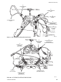
FORM 160.67-RP2 (507)
8&9
COMPRESSOR DISCHARGE
TEMPERATURE SENSOR
PRV POSITION KIT
(SEE FIG. 15A FOR
INSTALLATION)
LD10204
24
PRV ACTUATOR
1&4
COMPRESSOR HIGH OIL
PRESSURE TRANSDUCER
28
ACCELEROMETER KIT
28
ACCELEROMETER KIT
23
COMPRESSOR THRUST
PRESSURE SWITCH
FIG. 15 - "H"/"P" COMPRESSORS
30
LD10201
JOHNSON CONTROLS
FORM 160.67-RP2 (507)
27
POT
VANE MOTOR
LINKAGE
26
PRV POSITION KIT
CAP
PRV WASHER
EXISTING CONTROL
SHAFT COVER SCREWS
PRV
BRACKET
EXISTING CONTROL
SHAFT COVER
EXISTING PRV
LEVER
VANE MOTOR
LD10205
FIG. 15A - PRV POSITION KIT
KG TURBINE
16
TURBINE
OIL COOLER WATER
BALL VALVE
FIG. 16 - KG TURBINE OIL COOLER WATER PIPING
JOHNSON CONTROLS
LD10207
31
FORM 160.67-RP2 (507)
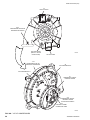
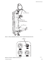
29, 56, 57
STEAM EXHAUST
PRESSURE
TRANSMITTER
SENTINAL WARNING
VALVE
32 OR 33, 56, 57
FIRST STAGE
PRESSURE
TRANSMITTER
43
VACUUM BREAKER
SOLENOID VALVE
45
TURBINE TRIP
VALVE LIMIT SWITCH
SHAFT OIL PUMP
TURBINE AUXILIARY
OIL PUMP MOTOR
GLAND LEAK-OFF
CONNECTION
OIL RESERVOIR
40
TURBINE SUPPLY
OIL TEMPERATURE
SENSOR
OIL FILTER
OIL COOLER
FIG. 17 - KD TURBINE
32
30, 57
TURBINE SUPPLY
OIL PRESSURE
TRANSMITTER
44
TURBINE TRIP
SOLENOID VALVE
HAND
TRIP KNOB
LD12634
JOHNSON CONTROLS
FORM 160.67-RP2 (507)
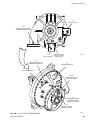
29, 56, 57
STEAM EXHAUST
PRESSURE
TRANSMITTER
SENTINAL WARNING
VALVE
32 OR 33, 56, 57
FIRST STAGE
PRESSURE
TRANSMITTER
43
VACUUM BREAKER
SOLENOID VALVE
GOVERNOR END
BEARING
(SEE FIG. 19)
BREATHER FILTER
ASSEMBLY
CONSTANT
LEVEL OILER
GLAND LEAK-OFF
CONNECTION
45
TURBINE TRIP VALVE
LIMIT SWITCH
LEVEL GAUGE
44
TURBINE TRIP
SOLENOID VALVE
HAND TRIP KNOB
FIG. 17A - KG TURBINE
JOHNSON CONTROLS
LD10209
33
FORM 160.67-RP2 (507)
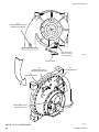
47
TURBINE VIBRATION
CABLE
46
8MM VIBRATION
PROBE
47
TURBINE VIBRATION
CABLE
35
MAGNETIC
PICK-UP
CABLE
39
SPRING LOADED FLUID
SEAL HOLDER
46
8MM VIBRATION
PROBE
34
MAGNETIC
PICK-UP
(FOR SPEED SWITCH)
38
TURBINE SHAFT END
BEARING TEMPERATURE
SENSOR
37
MAGNETIC PICK-UP
CABLE
36
MAGNETIC PICK-UP
(FOR ANALOG SPEED SIGNALS)
LD10214
FIG. 18 - KD TURBINE SHAFT END BEARING
38
TURBINE SHAFT END
BEARING TEMPERATURE
SENSOR
39
SPRING LOADED FLUID
SEAL HOLDER
FIG. 18A - KG TURBINE SHAFT END BEARING
34
LD10215
JOHNSON CONTROLS
FORM 160.67-RP2 (507)
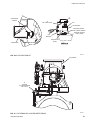
46
8 MM VIBRATION
PROBE
47
TURBINE VIBRATION
CABLE
46
8 MM VIBRATION
PROBE
47
TURBINE VIBRATION
CABLE
38
TURBINE GOVERNOR
END BEARING
TEMPERATURE SENSOR
39
SPRING LOADED
FLUID SEAL
HOLDER
LD10216
FIG. 19 - KD TURBINE GOVERNOR END BEARING
39
SPRING LOADED
FLUID SEAL
HOLDER
35
MAGNETIC PICKUP CABLE
(FOR ITEM 34)
100
38
TURBINE GOVERNOR
END BEARING
TEMPERATURE SENSOR
150
200
50
0
F
250
OFFTT
RO
AS HC R
37
MAGNETIC
PICK-UP CABLE
37
MAGNETIC
PICK-UP CABLE
36
MAGNETIC PICK-UP
(FOR ANALOG
SPEED SIGNALS)
FIG. 19A - KG TURBINE GOVERNOR END BEARING
JOHNSON CONTROLS
34
MAGNETIC PICK-UP
(FOR SPEED SWITCH)
LD10217
35
FORM 160.67-RP2 (507)
EXHAUST PRESSURE
GAUGE CONNECTION
49
TURBINE NOZZLE VALVE
AIR DUMP SOLENOID VALVE
EXHAUST END
CASING DRAIN
49
TURBINE NOZZLE VALVE
AIR DUMP SOLENOID VALVE
CHECK
VALVE
GLAND LEAK-OFF
48
STEAM RING DRAIN
SOLENOID VALVE
NOZZLE INLET
PRESSURE GAUGE
CONNECTION
LD12636
FIG. 20 - TURBINE STEAM RING DRAIN & NOZZLE VALVE AIR DUMP SOLENOID VALVES
36
JOHNSON CONTROLS
FORM 160.67-RP2 (507)
50
LEVEL TRANSMITTER
6
3
1ft
51
HIGH LEVEL SWITCH
9
51
LOW LEVEL SWITCH
6
3
LD10218
FIG. 21 - STEAM CONDENSER HOTWELL LEVEL TRANSMITTER AND SWITCHES
55
TACHOMETER
125 150 175
200
100
225
75
250
50
275
25
300
0
00 00
RPM
DYNALCO
ASHCROFT
TURBINE SPEED
TURBINE SPEED
125 150 175
200
100
75
225
50
250
275
300
25
0
ASHCROFT
10
15
20
25
30
5
0
3
6
9
12
14
ASHCROFT
TURBINE SPEED
EXHAUST PRESSURE
FIG. 22 - OPTIONAL TURBINE GAUGE BOARD
JOHNSON CONTROLS
LD10219
37
FORM 160.67-RP2 (507)
NOTES
38
JOHNSON CONTROLS
FORM 160.67-RP2 (507)
NOTES
JOHNSON CONTROLS
39
P.O. Box 1592, York, Pennsylvania USA 17405-1592
Copyright © by Johnson Controls Inc. 2007
Form: 160.67-RP2 (507)
Supersedes: 160.67-RP2 (1004)
Tele. 800-861-1001
www.york.com
Subject to change without notice. Printed in USA
ALL RIGHTS RESERVED