1
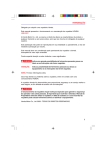
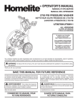
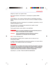
OPERATOR’S SAFETY
AND SERVICE MANUAL
SCREEDEMON
This manual covers the following serial numbers
and higher for each model listed:
WS500 . . . . . . . . . . . . . . . . . . . 1410030
WET SCREED
MBW, Inc.
MBW (UK) Ltd.
MBW France S.A.R.L
250 Hartford Rd • PO Box 440
Slinger, WI 53086-0440
Phone: (262) 644-5234
Fax: (262) 644-5169
Email: [email protected]
Website: www.mbw.com
Units 2 & 3 Cochrane Street
Bolton BL3 6BN, England
Phone: 01204 387784
Fax: 01204 387797
Z.A. d’Outreville
11 rue Jean Baptiste Néron,
60540 BORNEL, France
Phone: 3 44 07 15 96
Fax: 3 44 07 41 28
L17763 / 10.09.M
©MBW, Inc. 2009
Printed in the USA
TABLE OF CONTENTS
Safety Information . . . . . . . . . . . . . . . . . . . . . . 1
Introduction . . . . . . . . . . . . . . . . . . . . . . . . . . . . . . . . . 1
Safety Precautions . . . . . . . . . . . . . . . . . . . . . . . . . . . 1
Safety Decals . . . . . . . . . . . . . . . . . . . . . . . . . . . . . . . 1
Specifications. . . . . . . . . . . . . . . . . . . . . . . . . . 3
Operation . . . . . . . . . . . . . . . . . . . . . . . . . . . . . 4
Maintenance Schedule. . . . . . . . . . . . . . . . . . . . . . . . 7
Engine Maintenance. . . . . . . . . . . . . . . . . . . . . . . . . . 7
Engine Speed. . . . . . . . . . . . . . . . . . . . . . . . . . . . . . . 7
Cleaning . . . . . . . . . . . . . . . . . . . . . . . . . . . . . . . . . . . 7
Service. . . . . . . . . . . . . . . . . . . . . . . . . . . . . . . . 8
Torque Chart . . . . . . . . . . . . . . . . . . . . . . . . . . . . . . . 8
Engine Mounting Flange Removal . . . . . . . . . . . . . . . 8
Introduction . . . . . . . . . . . . . . . . . . . . . . . . . . . . . . . . . 4
Handle Removal. . . . . . . . . . . . . . . . . . . . . . . . . . . . . 8
Before Starting & Operating . . . . . . . . . . . . . . . . . . . . 4
Exciter Disassembly . . . . . . . . . . . . . . . . . . . . . . . . . . 8
Attaching Blade. . . . . . . . . . . . . . . . . . . . . . . . . . . . . . 4
Exciter Assembly . . . . . . . . . . . . . . . . . . . . . . . . . . . . 9
Starting Engine . . . . . . . . . . . . . . . . . . . . . . . . . . . . . . 4
Engine Mounting Flange & Engine Assembly . . . . . . 9
Stopping Engine . . . . . . . . . . . . . . . . . . . . . . . . . . . . . 4
Parts Replacement Cycles and Tolerances . . . . . . . 10
Operation . . . . . . . . . . . . . . . . . . . . . . . . . . . . . . . . . . 5
Handle Adjustment . . . . . . . . . . . . . . . . . . . . . . . . . . . 6
Replacement Parts . . . . . . . . . . . . . . . . . . . . . 11
Kickstand . . . . . . . . . . . . . . . . . . . . . . . . . . . . . . . . . . 6
Main Assembly . . . . . . . . . . . . . . . . . . . . . . . . . . . . . 12
Transporting . . . . . . . . . . . . . . . . . . . . . . . . . . . . . . . . 6
Exciter Assembly . . . . . . . . . . . . . . . . . . . . . . . . . . . 14
Maintenance . . . . . . . . . . . . . . . . . . . . . . . . . . . 7
Engine and Engine Mount . . . . . . . . . . . . . . . . . . . . 16
Warranty . . . . . . . . . . . . . . . . . . . . . . . . . . . . . 18
WARNING
CALIFORNIA PROPOSITION 65 WARNING
Engine exhaust and some of its constituents are
known in the state of California to cause cancer,
birth defects, and other reproductive harm.
SAFETY INFORMATION
Introduction
SAFE DRESS: Do not wear loose clothing,
rings, wristwatches, etc. near machinery.
This Safety Alert Symbol is used to call attention
to items or operations which may be dangerous
to those operating or working with this
equipment.
The symbol can be found
throughout this manual and on the unit. Please read these
warnings and cautions, along with all decals, carefully
before attempting to operate the unit. Make sure every
individual who operates or works with this equipment is
familiar with all safety precautions.
NOISE PROTECTION: Wear OSHA specified
hearing protection devices.
EYE PROTECTION: Wear OSHA specified
eye shields, safety glasses, and sweat bands.
FOOT PROTECTION: Wear OSHA specified
steel-tipped safety shoes.
WARNING
HEAD PROTECTION: Wear OSHA specified
safety helmets.
GENERAL WARNING.
Indicates information
important to the proper operation of the
equipment. Failure to observe may result in
damage to the equipment and/or severe bodily
injury or death.
DUST PROTECTION: Wear OSHA specified
dust mask or respirator.
CAUTION
OPERATOR: Keep children and bystanders
off and away from the equipment.
GENERAL CAUTION.
Indicates information
important to the proper operation of the
equipment. Failure to observe may result in
damage to the equipment.
REFERENCES: For details on safety rules and regulations
in the United States, contact your local Occupational Safety
and Health Administration (OSHA) office. Equipment
operated in other countries must be operated and serviced
in accordance and compliance with any and all safety
requirements of that country. The publication of these
safety precautions is done for your information. MBW does
not by the publication of these precautions, imply or in any
way represent that these are the sum of all dangers present
near MBW equipment.
If you are operating MBW
equipment, it is your responsibility to insure that such
operation is in full accordance with all applicable safety
requirements and codes. All requirements of the United
States Federal Occupational Safety and Health
Administration Act must be met when operated in areas that
are under the jurisdiction of that United States Department.
Safety Precautions
LETHAL EXHAUST GAS: An internal
combustion engine discharges carbon
monoxide, a poisonous, odorless, invisible
gas. Death or serious illness may result if
inhaled. Operate only in an area with proper
ventilation.
NEVER OPERATE IN A
CONFINED AREA!
DANGEROUS FUELS: Use extreme caution
when storing, handling and using fuels, as
they are highly volatile and explosive in vapor
state. Do not add fuel while engine is running.
Stop and cool the engine before adding fuel.
DO NOT SMOKE!
Safety Decals
SAFETY GUARDS: It is the owner's
responsibility to ensure that all guards and
shields are in place and in working order.
Carefully read and follow all safety decals. Keep them in
good condition. If decals become damaged, replace as
required. If repainting the unit, replace all decals. Decals
are available from authorized MBW distributors. Order the
decal set listed on the following page(s).
IGNITION SYSTEMS: Breakerless, magneto,
and battery ignition systems can cause severe
electrical shocks. Avoid contacting these
units or their wiring.
-1-
U.S. PATENT 7,201,537
6,988,851 ; 7,204,659
19379
EXCITER
LOCATION
17768
EXCITER
LOCATION
17768
17770
17770
17769
Safety Decals (Decal Set #17782)
-2-
SPECIFICATIONS
500H
500H
500R
Operating Weight
29 lbs (13.2 kg)
29 lbs (13.2 kg)
Engine Make
Honda
Robin
Engine Model
GX35NTT3
EH035V
Displacement
3)
(2.04 in3) 33.5 cm3
(2.13 in
35
cm3
Spark Plug
NGK CMR5H
NGK CMR6A
Electrode Gap
0.024 -0.028in (0.6-0.7mm)
0.024 -0.028in (0.6-0.7mm)
Engine Oil Type
SAE 10W30
SAE 10W30
Engine Oil Capacity
3.4 oz (0.1L)
3.4 oz (0.1 L)
Fuel Type
Regular Unleaded
Regular Unleaded
Fuel Tank Capacity
0.17 gal (0.64 L)
0.17 gal (0.64 L)
Blade Specifications
Part #
Width
Weight
17804
4 ft (1.21 m)
8.1 lb (3.7 kg)
17806
6 ft (1.83 m)
12.1 lb (5.5 kg)
17808
8 ft (2.44 m)
16.1 lb (7.3 kg)
17810
10 ft (3.05 m)
20.1 lb (9.1 kg)
17812
12 ft (3.66 m)
24.0 lb (10.9 kg)
17814
14 ft (4.27 m)
28.0 lb (12.7 kg)
17816
16 ft (4.88 m)
32.0 lb (14.5 kg)
17818
18 ft (5.49 m)
36.0 lb (16.3 kg)
17820
20 ft (6.10 m)
40.0 lb (18.1 kg)
17824
24 ft (7.32 m)
47.9 lb (21.7 kg)
Specifications subject to change without notice
-3-
OPERATION
Introduction
MBW equipment is intended for use in very severe
applications. They are powered by four cycle engines and
are available in different sizes and a selection of engines.
Bolt
This parts manual contains only standard parts. Variations
of these parts as well as other special parts are not included.
Contact your local MBW distributor for assistance in
identifying parts not included in this manual.
Exciter
Clamping
Plate
Before Starting & Operating
Float Blade
Figure 1.
• REMEMBER! It is the owner’s responsibility to
communicate information on the safe use and proper
operation of this unit to the operators.
5.
• Review ALL of the Safety Precautions listed on page 1 of
this manual.
Set the exciter onto the blade so the rear part of the
exciter casting lines up with the rear cavity of the float
blade.
6.
Tighten the clamping plate bolts.
• Familiarize yourself with the operation of the machine
and confirm that all controls function properly.
Starting Engine
1.
Turn engine switch to “ON”.
2.
Press the primer bulb repeatedly until fuel can be
seen in the clear plastic return tube.
• Make sure hands, feet, and clothing are at a safe
distance from any moving parts.
3.
Choke engine if necessary (you may not need to
choke a warm engine).
• OIL LEVEL - Check the oil level in the engine. For more
information see “Lubrication” under the respective
engine’s “Owners Manual” or the Maintenance section of
this manual.
4.
Pull starter rope repeatedly until engine starts.
5.
If choke was moved to the closed position to start,
gradually move it to the open position as the engine
warms up.
• AIR CLEANER - Check to ensure element is in good
condition and properly installed.
6.
Allow engine to warm up for one or two minutes.
• Know how to STOP the machine in case of an
emergency.
Stopping Engine
• FUEL SUPPLY - The engines on MBW equipment
require an automotive grade of clean, fresh, unleaded
gasoline.
• FUEL FILTER - If clogged or damaged, replace.
Attaching Blade
1.
Move throttle to idle position.
2.
Let engine idle for one or two minutes.
3.
Turn switch on engine to “STOP” position.
4.
Turn off fuel valve.
WARNING
Refer to Figure 1.
1.
Always stop the engine before:
Loosen the bolts that secure the clamps to the exciter
assembly.
2.
Lay the float blade on the floor with the decals facing
upward.
3.
Center the exciter between the “Exciter Location”
decals on the float blade.
4.
Tilt the exciter forward and hook the small leg of the
clamping plates under the front lip of the float blade.
Adding fuel.
Leaving the equipment unattended for any
amount of time.
Before making any repairs or adjustments to the
machine.
-4-
Operation
Before placing the ScreeDemon in concrete make sure the
clamps securing the exciter to the float blade are tight.
Blade Length
A
CAUTION
Keep the blade clamps tight at all times. Operating the ScreeDemon with the clamps loose will
damage the float blade.
A
12-18"
CAUTION
Never run the ScreeDemon above idle when the
float blade is not in contact with concrete. This
can damage the float blade.
A
A
The ScreeDemon can be used with or without forms. The
following describes the use of the ScreeDemon without
forms.
1.
Step 1.
Use a hand float to make a 12-18” diameter wet pad
(A) at the desired grade in the four corners of the area
you wish to screed. The outer extents of the wet pads
should not exceed the length of the float blade being
used.
B
NOTE: Use a laser receiver, transit level, or grade
stakes to help establish the correct grade.
2.
Run the ScreeDemon between the wet pads to create
two parallel strips (B) that define the grade for the
remainder of the wet screeding. These strips should
be 12-18” wide.
B
Step 2.
B
3.
Place one end of the float blade on each of the
parallel strips (B) and screed the concrete (C) in
between the strips. Be sure the float blade follows
the contour of the parallel strips.
C
B
Step 3.
-5-
Handle Adjustment
The operator can adjust the handle on the
ScreeDemon to a comfortable position.
Handle
Adjustment
Knob
Refer to Figure 2.
1.
Loosen the handle by turning the handle
adjustment knob counter-clockwise.
2.
Move the handle to the desired position.
3.
Tighten the handle adjustment knob.
Kickstand
Kickstand
The kickstand will support the ScreeDemon in an
upright position when not in use.
Figure 2.
Transporting
It is recommended to transport the ScreeDemon with the
float bar removed. The float bar is more likely to be
damaged if attached to the main unit during transport.
The handle can be collapsed for easier transport.
Figure 3.
See
Figure 3.
-6-
MAINTENANCE
WARNING
CAUTION
Always exercise the stopping procedure before
servicing or lubricating the unit.
Always verify fluid levels and check for leaks after
changing fluids.
After servicing the unit, replace and fasten all
guards, shields, and covers to their original
positions before resuming operation.
Do not drain oil onto ground, into open streams,
or down sewage drains.
Maintenance Schedule
SYSTEM
MAINTENANCE
EACH USE
EVERY 20
HOURS
EVERY 100
HOURS
YEARLY
Engine
Refer to engine operator/owner manual
Hardware
Check and tighten as needed1
X
X
Shockmounts
Check for cracks or tears
X
X
1.
X
Check all hardware after the first 5 hours of use, then follow the maintenance schedule.
Engine Maintenance
Cleaning
Refer to the engine owner’s manual for maintenance
intervals and procedures.
Clean any concrete from the ScreeDemon immediately
after each use. DO NOT allow concrete to harden on
the screed.
Engine Speed
The idle speed of the engine should not exceed the
following:
1.
Use a hose to remove any excess concrete.
2.
Remove any buildup with hard plastic bristle brush.
NOTE: DO NOT use a wire brush, hammer, or pressure
washer to remove concrete from the main unit or
float blade.
Honda - 3500 rpm
Robin - 2000 rpm
If the idle speed is greater the clutch may not disengage.
Check engine owner’s manual for procedure on setting idle
speed.
-7-
3.
Remove the blade.
4.
Start engine and run the exciter for about 10 seconds.
5.
Shut down the engine.
SERVICE
Engine Mounting Flange Removal
Assembly and disassembly should be performed by a
service technician who has been factory trained on MBW
equipment. The unit should be clean and free of debris.
Cleaning unit before disassembly is recommended.
Refer to Engine and Engine Mount, page 16.
• Prior to assembly, wash all parts in a suitable cleaner or
solvent.
• Check moving parts for wear and failure. Refer to the
Replacement section in this manual for tolerance and
replacement cycles.
1.
Disconnect the throttle cable (#18, page 12) from the
engine (#8).
2.
Loosen the 6mm socket head cap screw (#2) located
at the base of the engine.
3.
Pull the engine off the engine mounting flange (#4).
NOTE: Silicon is used to seal the connection between
the engine and the engine mounting flange.
Rotating the engine will help break this seal.
• All shafts and housings should be oiled prior to pressing
bearings. Also, ensure that the bearings are pressed
square and are seated properly.
• All bearings should be replaced when rebuilding any
exciter or gearbox.
• All gaskets and seals should be replaced after any
disassembly.
4.
Remove the three hex head cap screws and sealing
washers (#20 & #5, page 12) from the engine
mounting flange.
5.
Remove the plug (#1) from the engine mounting
flange.
6.
Use an 1/8” allen wrench to loosen the pipe plug
(#12, page 14) inside the exciter housing (#4, page
14) directly below the hole.
7.
Stick a rod or screwdriver straight down through both
holes.
8.
Rotate the spline shaft (#6) until the exciter hits the
rod and the spline shaft can no longer turn.
9.
Use a pliers to grab the spline shaft below the spline.
Rotate the shaft counter-clockwise to remove the
engine mounting flange.
Torque Chart
SIZE
1/4-20
1/4-28
5/16-18
5/16-24
3/8-16
3/8-24
7/16-14
7/16-20
1/2-13
1/2-20
9/16-12
5/8-11
M6
M8
M 10
GRADE 2
GRADE 5
49 in•lbs
76 in•lbs
56 in•lbs
87 in•lbs
8 ft•lbs
13 ft•lbs
9 ft•lbs
14 ft•lbs
15 ft•lbs
23 ft•lbs
17 ft•lbs
26 ft•lbs
24 ft•lbs
37 ft•lbs
27 ft•lbs
41 ft•lbs
37 ft•lbs
57 ft•lbs
41 ft•lbs
64 ft•lbs
53 ft•lbs
82 ft•lbs
73 ft•lbs
112 ft•lbs
3 ft•lbs
4 ft•lbs
6 ft•lbs
10 ft•lbs
10 ft•lbs
20 ft•lbs
CONVERSIONS
in•lbs x 0.083 = ft•lbs
ft•lbs x 12 = in•lbs
ft•lbs x 0.1383 = kg•m
ft•lbs x 1.3558 = N•m
GRADE 8
9 ft•lbs
10 ft•lbs
18 ft•lbs
20 ft•lbs
33 ft•lbs
37 ft•lbs
52 ft•lbs
58 ft•lbs
80 ft•lbs
90 ft•lbs
115 ft•lbs
159 ft•lbs
7 ft•lbs
18 ft•lbs
30 ft•lbs
Handle Removal
Refer to Main Assembly, page 12.
1.
Disconnect the throttle cable (#18) from the engine.
2.
Remove the hex head cap screw (#26) and
lockwasher (#27) securing the rear shockmount (#2)
to the exciter (#15).
3.
Remove the two hex head cap screws (#26) and
lockwashers (#27) located at the base of the handle
mount (#9).
4.
Remove the handle mount from the exciter.
Exciter Disassembly
Refer to Exciter Assembly, page 14.
The engine mounting flange must be removed before
disassembling the exciter. See Engine Mounting
Flange Removal, page 8.
1.
-8-
Unthread the three shockmounts (#7) from the exciter
housing (#4). Unthread the shockmount from the
exciter shaft (#6).
2.
Loosen the three socket head cap screws (#13)
securing the exciter cover (#8) to the exciter housing.
Back the socket head cap screws out about 1/4”.
3.
Gently tap on the socket head cap screws with a
rubber mallet to push the exciter cover out of the
exciter housing.
4.
Remove the socket head cap screws and the fiber
washers (#11) after the exciter cover is free from the
exciter housing.
5.
Remove the bearings (#5) from the exciter housing,
exciter cover, and exciter shaft.
6.
Remove the socket head cap screw (#13) securing
the exciter weight (#3) to the exciter shaft (#6).
3.
Apply a small bead of Loctite 426 adhesive (MBW
#17885) to the lip on the engine mounting flange.
See Figure 4.
APPLY
ADHESIVE
HERE
Exciter Assembly
Refer to Exciter Assembly, page 14.
1.
Press a bearing (#5) into the exciter housing (#4) and
exciter cover (#8).
2.
Slide the exciter weight (#3) onto the exciter shaft
(#6).
4.
3.
Apply a medium strength threadlocker to the socket
head cap screw (#13) and use it to secure the exciter
weight into the exciter shaft.
Place a new rubber seal onto the engine mounting
flange and hold it in place for 10 seconds to allow the
adhesive to set up.
5.
Position the engine mounting flange (#4) so the plug
hole lines up with the socket head set screw (#12,
page 14) on the exciter.
4.
Figure 4.
Turn the exciter housing up-side-down and place the
the threaded end of the exciter shaft/weight
assembly into the bearing in the housing.
5.
Apply a light coat of grease to the top step of the
exciter cover (#8). Place a new o-ring (#1) onto the
greased step.
6.
Apply medium strength thread locker to the threaded
holes in the cover.
7.
Line up the mounting holes between the exciter
housing and exciter cover and assemble the exciter
cover to the exciter housing. Take care not to cut the
o-ring. Secure the cover with three socket head cap
screws and fiber washers (#11).
8.
Thread the four shockmounts (#7) into the exciter
housing and exciter shaft.
9.
Apply medium strength thread locker to the socket
head set screw (#12) and thread it into the exciter
housing.
NOTE: Do not use any sealant or adhesive between the
bottom of the rubber seal and the top of the exciter.
2.
Clean the surfaces of the engine mounting flange
(#4) where the rubber seal was glued.
7.
Secure the engine mounting flange with three sealing
washers (#5, page 12) and three hex head cap
screws (#20, page 12).
8.
Replace the plug (#1).
9.
Place a small bead of 100% silicon sealant around
the engine mounting flange about 1/2” from the top.
Also fill the slot on the engine housing with silicone.
NOTE: Make sure the engine slides all the way down to
the step on the engine mounting flange.
The
engine may have to be lifted and rotated to engage
the splines.
Refer to Engine and Engine Mount, page 16
Inspect the rubber seal (#9). Remove if there are any
tears or if it is worn. If the rubber seal is in good
condition, skip to step #5.
Set the engine mounting flange in place while turning
the spline shaft (#6) clockwise to thread the shaft into
the center shockmount (#7, page 14) on top of the
exciter housing (#4, page 14). This only needs to be
hand tight.
10. Orient the engine (#8) so the fuel tank faces away
from the operating position and slide the engine over
the engine mounting flange.
Engine Mounting Flange & Engine Assembly
1.
6.
11. Tighten the socket head cap screw (#2) at the base
of the engine.)
12. Reattach the throttle cable (#18, page 12 to the
engine.
-9-
Parts Replacement Cycles and Tolerances
Bearings
Replace anytime a bearing is rough, binding, discolored or removed from housing or
shaft.
Engine Components
Refer to your engine manufacturer’s Owner’s Manual.
Hardware
Replace any worn or damaged hardware as needed. Replacement hardware should
be grade 5 and zinc plated unless otherwise specified.
Safety Decals
Replace if they become damaged or illegible.
Seals, O-rings, & Gaskets
Replace if a leak is detected and at every overhaul or teardown.
- 10 -
REPLACEMENT PARTS
The warranty is stated in this book on page 18. Failure to
return the Warranty Registration Card renders the warranty
null and void.
MBW has established a network of reputable distributors/
dealers with trained mechanics and full facilities for
maintenance and rebuilding, and to carry an adequate parts
stock in all areas of the country. Their sales engineers are
available for professional consultation. If you cannot locate
an MBW distributor in your area, contact MBW or one of our
Sales Branches listed below.
DECAL
When ordering replacement parts, be sure to have the
following information available:
STAMP
• Model and Serial Number of machine when ordering
MBW parts
• Model and Serial Number of engine when ordering
engine parts
• Part Number, Description, and Quantity
• Company Name, Address, Zip Code, and Purchase
Order Number
• Preferred method of shipping
STAMP
REMEMBER - You own the best! If repairs are needed,
use only MBW parts purchased from authorized
MBW distributors.
The unit’s serial number can be found in the following
locations:
• The model/serial number decal is located on the handle
support on the underside of the handle clamp.
• The serial number is stamped on the handle support
below the serial number decal.
• The serial number is also stamped on the underside of
the exciter housing between the exciter and the
shockmount bolt.
Write Model Number here
Write Serial Number here
Contact Information
MBW, Inc.
MBW (UK) Ltd.
MBW France S.A.R.L
250 Hartford Rd • PO Box 440
Slinger, WI 53086-0440
Phone: (262) 644-5234
Fax: (262) 644-5169
Email: [email protected]
Website: www.mbw.com
Units 2 & 3 Cochrane Street
Bolton BL3 6BN, England
Phone: 01204 387784
Fax: 01204 387797
Z.A. d’Outreville
11 rue Jean Baptiste Néron,
60540 BORNEL, France
Phone: 3 44 07 15 96
Fax: 3 44 07 41 28
- 11 -
10
14
18
6
23
4
7
20
19
5
1
12
22
3
11
26
22
27
25
9
24
13
21
8
15
2
27
26
17
16
Main Assembly
- 12 -
DD
ITEM
1.
2.
3.
4.
5.
6.
7.
8.
9.
10.
11.
12.
13.
14.
15.
16.
17.
18.
19.
20.
21.
22.
23.
24.
25.
26.
27.
PART NO.
18472
17170
17245
17263
17639
17647
17649
17651
17727
17656
17660
17661
17662
17719
17726
17804
17806
17808
17810
17812
17814
17816
17818*
17820*
17824*
17831
17919
17793
F013203TCS
F042004HCS
F042032HCS
F0420ELN
F04PW
F051808SCS
F05LW
F081306HCS
F08LW
DESCRIPTION
GRIP, HANDLE
SHOCKMOUNT, 2” OD X 1-3/4” LONG
DOWEL PIN, 1/4” X 1.75”
LEVER, THROTTLE
WASHER, SEALING
KNOB, CLAMPING
CLAMP
STUD, 1/2-13 X 1-1/2” LONG
MOUNT, HANDLE
HANDLE, LIFTING
STAND
WASHER, NYLON
CAP
HANDLE
EXCITER ASSEMBLY
4’ FLOAT
6’ FLOAT
8’ FLOAT
10’ FLOAT
12’ FLOAT
14’ FLOAT
16’ FLOAT
18’ FLOAT
20’ FLOAT
24’ FLOAT
END CAPS, FLOAT (CONTAINS ALL 4 CAPS NEEDED FOR FLOAT)
CABLE, THROTTLE (HONDA ENGINE)
CABLE, THROTTLE (ROBIN ENGINE)
THREAD CUTTING SCREW, #6-32 X 3/8”
HEX HEAD CAP SCREW, 1/4”-20 X 1/2”
HEX HEAD CAP SCREW, 1/4”-20 X 4”
LOCKNUT, 1/4”-20
WASHER, 1/4”
SOCKET HEAD CAP SCREW, 5/16”-18 X 1”
LOCKWASHER, 5/16”
HEX HEAD CAP SCREW, 1/2”-13 X 3/4”
LOCKWASHER, 1/2”
*Dual power heads required for 18’ blades and above.
- 13 -
QTY
2
1
1
1
3
1
1
1
1
1
1
2
2
1
1
1
1
1
1
1
1
1
1
1
1
2
3
1
2
1
2
2
1
1
Exciter Assembly
- 14 -
ITEM
1.
2.
3.
4.
5.
6.
7.
8.
9.
10.
11.
12.
13.
14.
15.
16.
17.
18.
PART NO.
06237
17170
17629
17640
17643
17645
18547
17736
17863
19864
F042003SSS
F042008SCS
F061618HCS
F0616DLN
F06LW
F06SW
F081306HCS
F08LW
DESCRIPTION
O-RING, 4.33 ID X 0.103
SHOCKMOUNT, 2” OD X 1-3/4” LONG
HOUSING, EXCITER
BEARING, BALL
SHOCKMOUNT, 1” OD X 1” LONG
COVER, EXCITER
KIT, CLAMPS (INCLUDES TWO CLAMPS AND ALL NECASSARY HARDWARE)
NUT, SQUARE, 3/8”-16
WASHER, FIBER, 0.25 X 0.38 X 0.03
EXCITER, SCREEDEMON
SOCKET HEAD SET SCREW, 1/4-20 X 3/8”
SOCKET HEAD CAP SCREW, 1/4”-20 X 1”
HEX HEAD CAP SCREW, 3/8”-16 X 2-1/4”
LOCKNUT, 3/8”-16 DEFORMED
LOCKWASHER, 3/8”
WASHER, 3/8”
HEX HEAD CAP SCREW, 1/2”-13 X 3/4”
LOCKWASHER, 1/2”
- 15 -
QTY
1
2
1
2
4
1
1
2
3
1
1
3
2
2
2
2
2
Engine and Engine Mount
- 16 -
ITEM
1.
2.
3.
4.
5.
6.
7.
8.
9.
10.
11.
PART NO.
09618
15304
17296
17634
17635
17636
17637
17711
19211
17792
19226
M05C016BCS
DESCRIPTION
FITTING, PLUG
SCS, M6 X 25mm
SWITCH, ENGINE STOP
FLANGE, ENGINE MOUNT
BEARING, BALL, SEALED, 6800
SPLINE SHAFT (DOES NOT INCLUDE ITEM 8)
STUD, 1/4-20 X 3/4
RUBBER SEAL
ENGINE, HONDA GX31TA2 (Includes 3, 10 & 11)
ENGINE, ROBIN EH035V
SPACER, KILLSWITCH, PLATED
BCS, M5 X 16mm
QTY
1
1
1
1
1
1
1
1
1
1
1
1
17885
ADHESIVE, 426 LOCTITE, 10g (NOT SHOWN)
1
- 17 -
WARRANTY
WHAT DOES THIS WARRANTY COVER? MBW, Incorporated (MBW)
warrants each New Machine against defects in material and workmanship
for a period of twelve (12) months. "New Machine" means a machine
shipped directly from MBW or authorized MBW dealer to the end user. This
warranty commences on the first day the machine is sold, assigned to a
rental fleet, or otherwise put to first use.
batteries, and the like, all of which are sold AS IS/WHERE IS WITH ALL
FAULTS.
MBW warrants each Demonstration Machine against defects in material
and workmanship for a period of six (6) months. "Demonstration Machine"
means a machine used by MBW or its agents for promotional purposes.
This warranty commences on the first day the machine is sold, assigned to
a rental fleet, or otherwise put to first use.
6.This warranty does not cover any updates to any New Machine,
Demonstration Machine, or any other MBW product. MBW reserves the
right to improve or make product changes without incurring any obligation
to update, refit, or install the same on New Machines or Demonstration
Machines previously sold.
This warranty covers the labor cost for replacement or repair of parts,
components, or equipment on New Machines or Demonstration Machines,
and MBW shall pay labor costs at MBW's prevailing rate to affect the
warranted repair or replacement. MBW reserves the right to adjust labor
claims on a claim-by-claim basis.
WHAT MUST YOU DO TO OBTAIN WARRANTY COVERAGE? Each
New Machine or Demonstration Machine is accompanied by a Warranty
Registration Card. You must sign, date, and return the Warranty
Registration Card to the place of origin of the New Machine or
Demonstration Machine, either to MBW, Inc. at P.O. Box 440, Slinger,
Wisconsin 53086, MBW (UK), Ltd. at Units 2 & 3 Cochrane Street, Bolton
BL3 6BN, United Kingdom or MBW FRANCE SARL at
ZA D'Outreville, 5 Rue Jean Baptiste Neron, Bornel 60540 France, within
ten (10) days after purchase, assignment to a rental fleet, or first use. This
signed warranty card is the buyer's affirmation that he has read,
understood, and accepted the warranty at the time of purchase. Failure to
return the warranty card as specified herein renders the warranty null and
void. In order to receive warranty coverage consideration, warranty claims
must be submitted within thirty (30) days after the New Machine or
Demonstration Machine fails. Warranty claims must be submitted to MBW,
Inc., MBW (UK), Ltd. or MBW FRANCE SARL, and written authorization for
the return of merchandise or parts under the warranty must be obtained
before shipment to MBW.
This warranty covers the shipping cost of replacement parts, components,
or equipment via common ground carriers from MBW to an authorized
MBW dealer. Air freight is considered only in cases where ground
transportation is not practical.
MAY THIS WARRANTY BE TRANSFERRED? This warranty is nontransferable and only applies to the original end user of a new machine or
demonstration machine.
WHAT DOES THIS WARRANTY NOT COVER?
1.This warranty does not cover any Used Equipment. "Used Equipment"
means any MBW machine or equipment that is not a New Machine or a
Demonstration Machine. All Used Equipment is sold AS IS/WHERE IS
WITH ALL FAULTS.
2.This warranty does not cover any New Machine, Demonstration
Machine, or their equipment, parts, or components altered or modified in
any way without MBW's prior written consent. This warranty does not
cover the use of parts not specifically approved by MBW for use on MBW
products. This warranty does not cover misuse, neglect, shipping damage,
accidents, acts of God, the operation of any New Machine or
Demonstration Machine in any way other than recommended by MBW in
accordance with its specifications, or any other circumstances beyond
MBW's control. This warranty does not cover any New Machine or
Demonstration Machine repaired by anyone other than MBW factory
branches or authorized MBW distributors.
3.This warranty does not cover, and MBW affirmatively disclaims, liability
for any damage or injury resulting directly or indirectly from design,
materials, or operation of a New Machine or Demonstration Machine or any
other MBW product. MBW's liability with respect to any breach of warranty
shall be limited to the provisions of this document and in no event shall
exceed an amount equal to the purchase price of the New Machine or
Demonstration Machine purchased from MBW.
4.This warranty does not cover engines, motors, and other assemblies or
components produced by other manufacturers and used on a New
Machine or Demonstration Machine, as said engines, motors, and other
assemblies or components may have warranties provided by the
manufacturer thereof. This warranty does not apply to consumable items,
such as v-belts, filters, trowel and screed blades, seals, shock mounts,
5.This warranty does not cover the cost of transportation and other
expenses which may be connected with warranty service but not
specifically mentioned herein.
WHAT WILL MBW DO? MBW's obligation under this warranty is limited to
the replacement or repair of parts for a New Machine or Demonstration
Machine at MBW factory branches or at authorized MBW distributors, and
such replacement or repair is the exclusive remedy provided hereunder.
Labor must be performed at an authorized MBW distributor. MBW
reserves the right to inspect and render a final decision on each warranty
case, and MBW's repair or replacement is solely within the discretion of
MBW.
IT IS EXPRESSLY AGREED THAT THIS SHALL BE THE SOLE AND
EXCLUSIVE REMEDY UNDER THIS WARRANTY. UNDER NO
CIRCUMSTANCES SHALL MBW BE LIABLE FOR ANY COSTS, LOSS,
EXPENSE, DAMAGES, SPECIAL DAMAGES, INCIDENTAL DAMAGES,
OR PUNITIVE DAMAGES ARISING DIRECTLY OR INDIRECTLY FROM
THE USE OF THE NEW MACHINE OR DEMONSTRATION MACHINE
WHETHER BASED UPON WARRANTY, CONTRACT, NEGLIGENCE,
STRICT LIABILITY, OR ANY OTHER LEGAL THEORY.
THE FOREGOING WARRANTY IS EXPRESSLY IN LIEU OF ALL
OTHER WARRANTIES, EXPRESS OR IMPLIED, INCLUDING THE
WARRANTIES OF MERCHANTABILITY, FITNESS FOR USE, AND
FITNESS FOR A PARTICULAR PURPOSE, AND ALL OTHER
OBLIGATIONS OR LIABILITY ON MBW'S PART. MBW NEITHER
ASSUMES NOR AUTHORIZES ANY OTHER PERSON TO ASSUME ON
BEHALF OF MBW ANY OTHER LIABILITY OR WARRANTY IN
CONNECTION WITH THE SALE OR SERVICE OF ANY NEW MACHINE,
DEMONSTRATION MACHINE , OR ANY OTHER MBW PRODUCT.
- 18 -