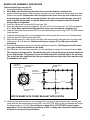
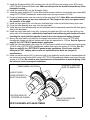
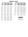
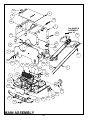
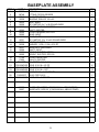
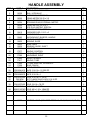
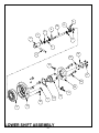
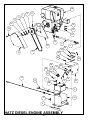
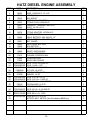
1
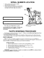
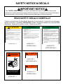
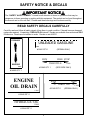
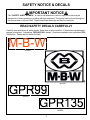
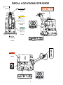
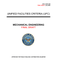
Operator's
Safety
and
Service
Manual
GPR135DE
(DIESEL)
GPR99H
(GASOLINE)
It is the OWNER’S RESPONSIBILITY to communicate information on the SAFE USE and
OPERATION of this machine to the operators!
MBW INC.
250 HARTFORD ROAD • P.O. BOX 440
SLINGER, WI 53086-0440
PHONE: (262) 644-5234 • FAX (262) 644-5169
MBW CORPORATE INTERNET ADDRESS
E-MAIL: [email protected]
WEB SITE: www.mbw.com
L17433 / 04.03.D
©MBW Inc. 2003
Printed in U.S.A
IN ENGLAND:
MBW (UK) LIMITED
Bradley Fold Trading Estate Unit 6
Radcliffe Moor Road
Bolton BL2 6RT
Phone: 01204 387784 • Fax: 01204 387797
SERIAL NUMBER LOCATION
1. Serial number decal location for MBW
reversible plate compactors.
2. Serial number is also stamped on the baseplate
housing (top edge near right rear shockmount)
and engine deck (back edge near handle).
1
(Write model number in box)
(Write serial number in box)
2
The units year of Manufacture can be
determined by the serial number. Contact your
nearest Sales Branch or MBW Inc. for this
information
STAMPED SERIAL NUMBER
LOCATIONS
PARTS ORDERING PROCEDURE
The Warranty is stated in this book on page 40 . Failure to return Warranty Registration Card
renders the Warranty null and void.
An “Owner’s Manual” for the engine is also furnished. Engine parts may be ordered from any
authorized dealer. Refer to the engine “Owner’s Manual” for exploded views and part identifications.
PARTS ORDERING:
MBW Inc. parts are available worldwide and must be ordered through your local MBW Inc.
distributor. If you cannot locate an MBW Inc. distributor in your area, refer to page 41 of this manual to
locate the MBW Inc. Sales Branch nearest you and call for assistance.
ALWAYS INCLUDE:
1. Model and Serial Number of machine when ordering MBW Inc. Parts.
2. Model and Serial Number of engine when ordering Engine Parts.
3. Item Part Number, Description, and Quantity.
4. Company Name, Address, Zip Code, and Purchase Order Number.
5. Preferred method of shipping.
REMEMBER - you own the best. If repairs are needed use only MBW Inc. parts purchased
from Authorized MBW Inc. distributors.
i
SAFETY PRECAUTIONS
READ AND STUDY THE FOLLOWING SAFETY INFORMATION BEFORE ATTEMPTING TO
OPERATE THIS EQUIPMENT. IN ADDITION, ENSURE THAT EVERY INDIVIDUAL WHO
OPERATES OR WORKS WITH THIS EQUIPMENT IS FAMILIAR WITH THESE SAFETY
PRECAUTIONS.
WARNING - LETHAL EXHAUST GAS!
An internal combustion engine discharges carbon monoxide, a poisonous, odorless invisible gas.
Death or serious illness may result if inhaled. Operate only in an area with good ventilation, NEVER IN
A CONFINED AREA!
WARNING - DANGEROUS FUELS!
Use extreme caution when storing, handling and using fuels - they are highly volatile and explosive
in vapor state. Do not add fuel while engine is running. Stop and cool the engine before adding fuel.
DO NOT SMOKE!
SAFETY GUARDS
It is the owner's responsibility to ensure ALL GUARDS AND SHIELDS are in place and in working
order.
IGNITION SYSTEMS
Breakerless, magneto and battery ignition systems CAN CAUSE SEVERE ELECTRICAL
SHOCKS. Avoid contacting these units or their wiring.
SAFE DRESS
DO NOT WEAR loose clothing, rings, wristwatches, etc., near machinery.
NOISE PROTECTION
Wear O.S.H.A. specified hearing protection devices.
FOOT PROTECTION
Wear O.S.H.A. specified steel tip safety shoes.
HEAD PROTECTION
Wear O.S.H.A. specified safety helmets.
EYE PROTECTION
Wear O.S.H.A. specified eye shields, safety glasses, and sweat bands.
DUST PROTECTION
Wear O.S.H.A. specified dust mask or respitator.
OPERATOR
Keep children and bystanders off and away from the equipment.
REFERENCES
For details on safety rules and regulations in the United States, contact your local Occupational
Safety and Health Administration (O.S.H.A.) office. Equipment operated in other countries must be
operated and serviced in accordance and compliance with any and all safety requirements of that
country.The publication of these safety precautions is done for your information. MBW Inc. does not by
the publication of these precautions, imply or in any way represent that these are the sum of all dangers
present near MBW equipment. If you are operating MBW Inc. equipment, it is your responsibility to
insure that such operation is in full accordance with all applicable safety requirements and codes. All
requirements of the United States Federal Occupational Safety and Healthy Administration Act must be
met when operated in areas that are under the jurisdiction of that United States Department.
ii
TABLE OF CONTENTS
Serial Number Location . . . . . . . . . . . . . . . . . . . . . . . . . . . . . . . . . . . . . . . . . . . . . . . . . . . . . . . . . . . . . i
Parts Ordering Procedure . . . . . . . . . . . . . . . . . . . . . . . . . . . . . . . . . . . . . . . . . . . . . . . . . . . . . . . . . . . i
Safety Precautions. . . . . . . . . . . . . . . . . . . . . . . . . . . . . . . . . . . . . . . . . . . . . . . . . . . . . . . . . . . . . . . . . ii
Safety Notice & Decals . . . . . . . . . . . . . . . . . . . . . . . . . . . . . . . . . . . . . . . . . . . . . . . . . . . . . . . . . . . . . 1
Decal Locations GPR135DE . . . . . . . . . . . . . . . . . . . . . . . . . . . . . . . . . . . . . . . . . . . . . . . . . . . . . . . . . 4
Decal Locations GPR99H . . . . . . . . . . . . . . . . . . . . . . . . . . . . . . . . . . . . . . . . . . . . . . . . . . . . . . . . . . . 5
Operating Instructions . . . . . . . . . . . . . . . . . . . . . . . . . . . . . . . . . . . . . . . . . . . . . . . . . . . . . . . . . . . . . . 6
Introduction . . . . . . . . . . . . . . . . . . . . . . . . . . . . . . . . . . . . . . . . . . . . . . . . . . . . . . . . . . . . . . . . . . 6
Before Operation . . . . . . . . . . . . . . . . . . . . . . . . . . . . . . . . . . . . . . . . . . . . . . . . . . . . . . . . . . . . . . 6
Operating . . . . . . . . . . . . . . . . . . . . . . . . . . . . . . . . . . . . . . . . . . . . . . . . . . . . . . . . . . . . . . . . . . . . 7
Engine . . . . . . . . . . . . . . . . . . . . . . . . . . . . . . . . . . . . . . . . . . . . . . . . . . . . . . . . . . . . . . . . . . . . . . 7
Starting Engine . . . . . . . . . . . . . . . . . . . . . . . . . . . . . . . . . . . . . . . . . . . . . . . . . . . . . . . . . . . . . . . 7
Starting Diesel Engine . . . . . . . . . . . . . . . . . . . . . . . . . . . . . . . . . . . . . . . . . . . . . . . . . . . . . . . . . . 7
Running Engine . . . . . . . . . . . . . . . . . . . . . . . . . . . . . . . . . . . . . . . . . . . . . . . . . . . . . . . . . . . . . . . 7
Stopping Engine. . . . . . . . . . . . . . . . . . . . . . . . . . . . . . . . . . . . . . . . . . . . . . . . . . . . . . . . . . . . . . . 7
Maintenance Schedule . . . . . . . . . . . . . . . . . . . . . . . . . . . . . . . . . . . . . . . . . . . . . . . . . . . . . . . . . . . . . 8
Fluid Levels . . . . . . . . . . . . . . . . . . . . . . . . . . . . . . . . . . . . . . . . . . . . . . . . . . . . . . . . . . . . . . . . . . . . . . 8
Specifications. . . . . . . . . . . . . . . . . . . . . . . . . . . . . . . . . . . . . . . . . . . . . . . . . . . . . . . . . . . . . . . . . . . . . 9
Troubleshooting . . . . . . . . . . . . . . . . . . . . . . . . . . . . . . . . . . . . . . . . . . . . . . . . . . . . . . . . . . . . . . . . . . 10
Service . . . . . . . . . . . . . . . . . . . . . . . . . . . . . . . . . . . . . . . . . . . . . . . . . . . . . . . . . . . . . . . . . . . . . . . . . 11
Engine Maintenance . . . . . . . . . . . . . . . . . . . . . . . . . . . . . . . . . . . . . . . . . . . . . . . . . . . . . . . . . . 11
Engine Speed . . . . . . . . . . . . . . . . . . . . . . . . . . . . . . . . . . . . . . . . . . . . . . . . . . . . . . . . . . . . . . . 11
Battery Maintenance . . . . . . . . . . . . . . . . . . . . . . . . . . . . . . . . . . . . . . . . . . . . . . . . . . . . . . . . . . 11
Battery Charging . . . . . . . . . . . . . . . . . . . . . . . . . . . . . . . . . . . . . . . . . . . . . . . . . . . . . . . . . . . . . 11
Main Disassembly Procedure (Diesel Engine). . . . . . . . . . . . . . . . . . . . . . . . . . . . . . . . . . . . . . . 11
Main Disassembly Procedure (Gasoline Engine) . . . . . . . . . . . . . . . . . . . . . . . . . . . . . . . . . . . . 13
Belt Adjustment . . . . . . . . . . . . . . . . . . . . . . . . . . . . . . . . . . . . . . . . . . . . . . . . . . . . . . . . . . . . . . 13
Exciter Oil Change Procedure . . . . . . . . . . . . . . . . . . . . . . . . . . . . . . . . . . . . . . . . . . . . . . . . . . . 14
Lower Hydraulic Seal Replacement. . . . . . . . . . . . . . . . . . . . . . . . . . . . . . . . . . . . . . . . . . . . . . . 15
Bleeding and Adjustment of Hydraulic Controls. . . . . . . . . . . . . . . . . . . . . . . . . . . . . . . . . . . . . . 16
Baseplate Disassembly Procedure . . . . . . . . . . . . . . . . . . . . . . . . . . . . . . . . . . . . . . . . . . . . . . . 17
Handle Disassembly Procedure. . . . . . . . . . . . . . . . . . . . . . . . . . . . . . . . . . . . . . . . . . . . . . . . . . 18
Control Head Disassembly Procedure. . . . . . . . . . . . . . . . . . . . . . . . . . . . . . . . . . . . . . . . . . . . . 19
Baseplate Assembly Procedure. . . . . . . . . . . . . . . . . . . . . . . . . . . . . . . . . . . . . . . . . . . . . . . . . . 20
Control Head Assembly Procedure . . . . . . . . . . . . . . . . . . . . . . . . . . . . . . . . . . . . . . . . . . . . . . . 23
Handle Assembly Procedure . . . . . . . . . . . . . . . . . . . . . . . . . . . . . . . . . . . . . . . . . . . . . . . . . . . . 24
Final Assembly. . . . . . . . . . . . . . . . . . . . . . . . . . . . . . . . . . . . . . . . . . . . . . . . . . . . . . . . . . . . . . . 24
Replacement . . . . . . . . . . . . . . . . . . . . . . . . . . . . . . . . . . . . . . . . . . . . . . . . . . . . . . . . . . . . . . . . . . . . 25
Torque Chart . . . . . . . . . . . . . . . . . . . . . . . . . . . . . . . . . . . . . . . . . . . . . . . . . . . . . . . . . . . . . . . . . . . . 26
Main Assembly . . . . . . . . . . . . . . . . . . . . . . . . . . . . . . . . . . . . . . . . . . . . . . . . . . . . . . . . . . . . . . . . . . 28
Baseplate Assembly . . . . . . . . . . . . . . . . . . . . . . . . . . . . . . . . . . . . . . . . . . . . . . . . . . . . . . . . . . . . . . 30
Handle Assembly . . . . . . . . . . . . . . . . . . . . . . . . . . . . . . . . . . . . . . . . . . . . . . . . . . . . . . . . . . . . . . . . 32
Lower Shift Assembly . . . . . . . . . . . . . . . . . . . . . . . . . . . . . . . . . . . . . . . . . . . . . . . . . . . . . . . . . . . . . 34
Honda Engine Assembly . . . . . . . . . . . . . . . . . . . . . . . . . . . . . . . . . . . . . . . . . . . . . . . . . . . . . . . . . . . 36
Hatz Diesel Engine Assembly . . . . . . . . . . . . . . . . . . . . . . . . . . . . . . . . . . . . . . . . . . . . . . . . . . . . . . . 38
Warranty . . . . . . . . . . . . . . . . . . . . . . . . . . . . . . . . . . . . . . . . . . . . . . . . . . . . . . . . . . . . . . . . . . . . . . . 40
Warehouse Locations . . . . . . . . . . . . . . . . . . . . . . . . . . . . . . . . . . . . . . . . . . . . . . . . . . . . . . . . . . . . . 41
iii
This page intentionally left blank
iv
SAFETY NOTICE & DECALS
IMPORTANT NOTICE
The “SAFETY ALERT SYMBOL” is used to call attention to items or operations that may be
dangerous to those operating or working with this equipment. The symbol can be found throughout
the manual and on the unit itself. Please read these warnings and cautions carefully.
READ SAFETY DECALS CAREFULLY
Carefully read and follow all safety decals. Keep them in good condition. If decals become damaged,
replace as required. If repainting, REPLACE ALL decals. Decals are available from authorized MBW
Distributors. Decals are not shown to scale. Decals on set #16031
CAUTION
Read the Operation Instructions before operating this
piece of equipment.
Keep unauthorized and untrained people away from this
equipment.
ROTATING & MOVING PARTS! Make sure all guards
and safety devices are in place.
DO NOT RUN this machine in an enclosed area. The
engine produces carbon monoxide, a POISONOUS
GAS.
Wear approved hearing protection, foot protection, eye
protection and head protection.
SHUT OFF the engine before servicing, cleaning or
adding fuel.
Failure to comply could result in serious bodily injury.
1.
2.
3.
4.
5.
6.
7.
8.
GASOLINE PLATE
OPERATING INSTRUCTIONS
Check engine oil level.
Open fuel valve.
Choke engine. A warm engine may not need to be
choked.
Open throttle part way.
Pull starter rope.
After starting: open choke, return throttle to idle
position.
During operation, when excessive kickback is
noticed, maximum compaction has been reached.
To stop, return throttle to the idle position, use
engine stop switch, close fuel valve.
15866
15867
#15867 QTY 1
DIESEL PLATE
OPERATING INSTRUCTIONS
1.
2.
3.
4.
Check engine oil level.
Check fuel level.
Set engine speed control in the middle position.
Move decompression lever (if equipped) to the up
position. (Located on top of the engine)
5. Use key (if equipped) or starting handle to start
engine (Refer to engine instruction book for proper
“Manual Starting” procedure.)
6. After starting return engine speed control to the idle
position and allow engine to reach operation
temperature.
7. During operation run engine at full throttle, when
excessive kickback is noticed maximum compaction
has been reached.
8. To stop, return throttle to the idle position and allow
engine to idle for one minute then move control to
stop position.
#15866 QTY 1
15832
(GPR99H ONLY)
#15832 QTY 1
(GPR135DE ONLY)
:$51,1*
WARNING
LIFT ONLY BY LIFT HOOK
APPROXIMATE WEIGHT: 924 LBS (420 KG)
15853
#15853 QTY 1
(GPR135DE ONLY)
WARNING
LIFT ONLY BY LIFT HOOK
APPROXIMATE WEIGHT: 781 LBS (355 KG)
527$7,1*3$576
.HHSKDQGVDZD\
16026
#16026 QTY 1
(GPR99H ONLY)
#13484 QTY 1
1
SAFETY NOTICE & DECALS
IMPORTANT NOTICE
The “SAFETY ALERT SYMBOL” is used to call attention to items or operations that may be
dangerous to those operating or working with this equipment. The symbol can be found throughout
the manual and on the unit itself. Please read these warnings and cautions carefully.
READ SAFETY DECALS CAREFULLY
Carefully read and follow all safety decals. Keep them in good condition. If decals become damaged,
replace as required. If repainting, REPLACE ALL decals. Decals are available from authorized MBW
Distributors. Decals are not shown to scale. Decals on set #16031
FORWARD
81/($'('*$62/,1(
#13481 QTY 1
RUN
REVERSE
14665
(GPR99H ONLY)
IDLE STOP
THROTTLE
15843
#15843 QTY 1
(GPR135DE ONLY)
#14665 QTY 1
ENGINE
OIL DRAIN
RUN
IDLE
THROTTLE
#17449 QTY 1
15845
#15845 QTY 1
HYDRAULIC OIL
15844
#15844 QTY 1
2
17449
(GPR99H ONLY)
SAFETY NOTICE & DECALS
IMPORTANT NOTICE
The “SAFETY ALERT SYMBOL” is used to call attention to items or operations that may be
dangerous to those operating or working with this equipment. The symbol can be found throughout
the manual and on the unit itself. Please read these warnings and cautions carefully.
READ SAFETY DECALS CAREFULLY
Carefully read and follow all safety decals. Keep them in good condition. If decals become damaged,
replace as required. If repainting, REPLACE ALL decals. Decals are available from authorized MBW
Distributors. Decals are not shown to scale.
M-B-W
#15847
#01554
15856
#15856
15855
#15855
3
DECAL LOCATIONS GPR135DE
HYDRAULIC OIL
M-B-W
15844
RUN
#15844
IDLE STOP
THROTTLE
15843
#15843
#15847
CAUTION
Read the Operation Instructions before operating this
piece of equipment.
Keep unauthorized and untrained people away from this
equipment.
ROTATING & MOVING PARTS! Make sure all guards
and safety devices are in place.
DO NOT RUN this machine in an enclosed area. The
engine produces carbon monoxide, a POISONOUS
GAS.
Wear approved hearing protection, foot protection, eye
protection and head protection.
SHUT OFF the engine before servicing, cleaning or
adding fuel.
Failure to comply could result in serious bodily injury.
15867
#15867
DIESEL PLATE
OPERATING INSTRUCTIONS
1. Check engine oil level.
2. Check fuel level.
3. Set engine speed control in the middle position.
4. Move decompression lever (if equipped) to the up
position. (Located on top of the engine)
5. Use key (if equipped) or starting handle to start
engine (Refer to engine instruction book for proper
“Manual Starting” procedure.)
6. After starting return engine speed control to the idle
position and allow engine to reach operation
temperature.
7. During operation run engine at full throttle, when
excessive kickback is noticed maximum compaction
has been reached.
8. To stop, return throttle to the idle position and allow
engine to idle for one minute then move control to
stop position.
#01554
15832
#15832
ENGINE
OIL DRAIN
15845
15855
#15845
#15855
FORWARD
WARNING
LIFT ONLY BY LIFT HOOK
APPROXIMATE WEIGHT: 880 LBS (400 KG)
16028
#15853
REVERSE
14665
#14665
:$51,1*
527$7,1*3$576
.HHSKDQGVDZD\
#13484
15855
#15855
#01554
4
DECAL LOCATIONS GPR99H
RUN
#13481
IDLE
THROTTLE
81/($'('*$62/,1(
17449
M-B-W
#17449
HYDRAULIC OIL
15844
#15844
#15847
#01554
15856
#15856
FORWARD
CAUTION
Read the Operation Instructions before operating this
piece of equipment.
Keep unauthorized and untrained people away from this
equipment.
ROTATING & MOVING PARTS! Make sure all guards
and safety devices are in place.
DO NOT RUN this machine in an enclosed area. The
engine produces carbon monoxide, a POISONOUS
GAS.
Wear approved hearing protection, foot protection, eye
protection and head protection.
SHUT OFF the engine before servicing, cleaning or
adding fuel.
Failure to comply could result in serious bodily injury.
:$51,1*
WARNING
527$7,1*3$576
.HHSKDQGVDZD\
LIFT ONLY BY LIFT HOOK
APPROXIMATE WEIGHT: 781 LBS (355 KG)
16026
#14665
15867
REVERSE
#15867
#13484
#16026
14665
ENGINE
OIL DRAIN
15845
#15845
ON ENGINE
DECK
GASOLINE PLATE
OPERATING INSTRUCTIONS
1. Check engine oil level.
2. Open fuel valve.
3. Choke engine. A warm engine may not need to be
choked.
4. Open throttle part way.
5. Pull starter rope.
6. After starting: open choke, return throttle to idle
position.
7. During operation, when excessive kickback is
noticed, maximum compaction has been reached.
8. To stop, return throttle to the idle position, use
engine stop switch, close fuel valve.
15866
#15866
15856
#15856
#01554
5
OPERATING INSTRUCTIONS
INTRODUCTION
MBW Inc. Compaction Equipment is intended for use in very severe applications. They are powered
by four stroke engines and are available in different sizes and a selection of engines.
The MBW Reversible Plate Compactor is intended to compact various soils types. Recommended
soil types include granular soils, gravel/sand mixtures, and semi-granular cohesive soils.
The MBW Reversible Plate Compactor is not recommended for use in cohesive soils nor for very
hard surfaces such as concrete or asphalt.
This parts manual contains only standard or standard option parts. Variations of these parts as well
as other special parts are not included. Contact your local MBW Inc. Distributor for assistance in
identifying parts not included in this manual.
BEFORE OPERATION
After receiving your new MBW Inc. Reversible Plate Compactor, inspect it for any visible damage done
during shipment. Make sure the engine throttle works properly. Contact your nearest MBW Inc. Distributor if
there are any problems.
Your new MBW Inc. Reversible Plate Compactor is shipped complete and ready for use.
REMEMBER! It is the owner's responsibility for communicating information on the safe use
and proper operation of this unit to the operators.
•
Before operating, review related SAFETY PRECAUTIONS listed on page ii of this manual.
•
Familiarize yourself with the operation of the equipment BEFORE starting the engine.
•
Know how to STOP the equipment.
•
Make sure hands, feet, and clothing are at a safe distance from any moveable parts prior to
starting.
•
OIL LEVEL- Check the oil level in the engine. For more information see “Lubrication” under
the respective engine's “Owner’s Manual” or the PERIODIC MAINTENANCE section of this
manual.
•
AIR CLEANER- Check to ensure element is in good condition and properly installed.
•
FUEL SUPPLY- The engines on MBW Inc. Compaction equipment require an automotive
grade of clean, fresh, diesel fuel or unleaded gasoline dependent on engine type. (See Engine
“Owner’s Manual”)
•
FUEL FILTER-If clogged or damaged, replace.
6
OPERATING
ENGINE
Refer to the engine manual for location of all controls and features.
STARTING ENGINE
For detailed instructions refer to the Engine Manual.
1. When starting engine, THROTTLE MUST BE IN AN IDLE POSITION. Open fuel valve. Choke
engine if necessary, (when starting a warm engine it may not be necessary to choke it).
2. Pull starter rope. After engine starts, the choke lever can be moved back to the open position. Let
the engine warm up in the idle position for one or two minutes.
STARTING DIESEL ENGINE
For detailed instructions refer to the Engine Manual.
1. When starting the engine, the THROTTLE LEVER ON THE HANDLE MUST BE IN AN IDLE
POSITION.
2. Slowly pull the starter rope to its full extended length to open the decompression valve in the engine.
Let the starter rope recoil completely and pull the starter rope quickly to start the engine. After the
engine starts make sure the throttle lever is in the idle position. Let the engine warm up in the idle
position for one or two minutes.
RUNNING ENGINE
1. After the engine warms up, fully open throttle. The compactor will begin vibrating and moving in a
forward direction. Never leave compactor idling unattended. The MBW Reversible Plate
Compactor is designed to slowly move forward without application of the control lever. The number
of passes needed to reach the compaction level desired will depend on soil type and moisture.
Maximum compaction of the soil has been reached when excessive kickback is noticed in the
compactor.
STOPPING ENGINE
1. To stop the compactor from traveling forward return the engine throttle to idle position.
2. Whenever possible, it is recommended to let the engine idle before stopping.
3. Gas engines: Turn the switch on the engine to “STOP” position.
Diesel engines: Move the throttle control to the “STOP” position.
4. Turn off the fuel valve where applicable.
STOP THE ENGINE BEFORE:
ADDING FUEL.
LEAVING EQUIPMENT UNATTENDED, EVEN IF ONLY FOR A MINUTE.
MAKING ANY REPAIRS OR ADJUSTMENTS TO UNIT.
7
MAINTENANCE SCHEDULE
Each
Use
System
Maintenance
Engine
Refer to engine operator/
owner manual
Every
50 Hours
Every
100 Hours
Every
250 Hours
x
Clean cooling fins
x
Belt
Check for wear and
retighten1
Exciter
Check for oil leaks
Yearly
x
x
x
Change oil
x
Tighten bolts1
x
x
x
Hydraulics
Check level and refill
x
Hardware
Check and tighten as
needed
x
x
Shock
Mounts
Check for cracks or tears
x
x
1. To be done after the first 5 hours, then do as shown in the maintenance schedule.
FLUID LEVELS
System
Fluid Volume
Recommended Brand
Engine Oil
Refer to engine operator/
owner manual
Refer to engine operator/owner
manual
GPR99
48 oz. (0.95 Liter)
MBW Inc. Ground Pounder®
Exciter Oil
GPR135
48 oz. (0.95 Liter)
MBW Inc. Ground Pounder®
Exciter Oil
GPR99
8 oz. (.24 Liter)
CHEVRON AW ISO32 OR
RYKON 32
GPR135
8 oz. (.24 Liter)
CHEVRON AW ISO32 OR
RYKON 32
Exciter Oil
Hydraulic Oil
8
SPECIFICATIONS
Specifications
Machine Data:
Operating Weight
GPR99H
814 lb
(369 kg)
Mechanical
w/V-belt
GPR135DE
925 lb
(420 kg)
Mechanical
Drive System
w/V-belt
Electric
Starter System
Recoil
w/Recoil
1.72 gal
1.32 gal
Fuel Capacity
(6.5 liters)
(5 liters)
19.7 in
19.7 in
Base Plate Width
(480 mm)
(480 mm)
Base Plate Length
37.2 in
37.2
(Overall)
(945mm)
(945 mm)
2 x 3/6 in
2 x 3/6 in
Extensions
(2 x 75/150 mm) (2 x 75/150 mm)
Performance:
9900 lbf
13500 lbf
Centrifugal Force
(44 kN/blow)
(60 kN/blow)
Exciter Speed
3840 vpm
3840 vpm
78 ft/min
76 ft/min
Travel Speed
(24m/min)
(23 m/min)
Engine Data:
3600 rpm
3600 rpm
Engine Speed
Make
Honda
Hatz
Model
GX340
1B40
Fuel
Gas
Diesel
Power
11.0 HP
9.9 HP
Data in parenthesis ( ) are Metric Measurements
Specifications are subject to change without notice.
9
TROUBLESHOOTING
Symptom
Engine does not start or stalls
Engine does not accelerate, is hard to start
or runs erratically.
Repair
1. No fuel in the tank.
2. The fuel valve is closed (gasoline engines).
3. On gasoline engines, the stop switch is not in
the ON position.
4. Fouled spark plugs (gasoline engines).
5. Electric Start; battery charge low (recharge).
6. Starter Motor defective or worn (replace).
7. Defective ignition switch (replace).
1.
2.
3.
4.
Improper fuel.
Spark plug or injection nozzle fouled (clean).
Fuel filter clogged (replace).
Air cleaner dirty or clogged (replace).
Engine overheats or runs hot.
1. Cooling fins and blower are dirty (clean).
Engine runs at full speed but machine
does not move.
1. Check the belt for excessive wear (replace).
2. Centrifugal clutch worn (replace).
Engine runs but machine operates
erratically.
1. Retension the belt (replace if needed).
2. Centrifugal clutch worn (replace).
Forward speed too slow.
1. Too much oil in the hydraulic head (reduce).
2. Improper adjustment of the control system
(requires authorized MBW service).
Reverse speed too slow.
1. Not enough oil in the hydraulic head (fill).
2. Air in control system (bleed).
3. Improper adjustment of of the control system
(requires authorized MBW service).
Plate vibrates but has no forward or
reverse movement.
1. Mechanical failure (requires authorized
MBW service).
Loss of hydraulic oil
1. Leaking hydraulic line connections (tighten /
replace).
2. Damaged hydraulic hose (replace).
3. Seal on the piston in gearbox is worn /
damaged (requires authorized MBW
service).
NOTE: If the engine performance is poor or erratic, check, clean and replace the air filter
and or the fuel filter as needed.
10
SERVICE
ENGINE MAINTENANCE
Refer to the engine owner’s manual for maintenance schedule.
ENGINE SPEED
1. The engine should be set at an operating speed of 3600 rpm. Check the engine owner's manual
for the procedure on setting the operating speed.
2. The idle speed of the engine must not exceed 1800 rpm. If the idle speed is greater the clutch may
not disengage. Check the engine owner's manual for the procedure on setting the idle speed.
BATTERY MAINTENANCE
The Odyssey battery is very different from standard liquid-acid batteries that are openly vented. The
battery is, and operates as, a sealed battery, recycling all gases internally. There is no corrosion to the
surrounding area. The battery is shipped fully charged from the factory, but prior to installation, check
the battery’s voltage to see if it is 12.65 volts or greater. If not, recharge it using the procedure below.
Caution: Never attempt to remove the top decal cover, as it will cause the battery to fail.
BATTERY CHARGING
The state of charge in an Odyssey battery can be determined from the following chart:
Voltmeter Reading
State of Charge
12.84 Volts
100%
12.50 Volts
75%
12.18 Volts
50%
11.88 Volts
25%
To get long life from the Odyssey battery, it is important that the battery is kept near full charge,
approximately 12.8 volts. If there are electrical loads during storage, then the negative battery cable
should be disconnected or a Battery Tender trickle charger used. Low power 1.25 amp Battery Tenders
will keep a fully charged battery fully charged but cannot recharge if the battery becomes discharged.
If a standard automotive charger is used to boost charge a discharged battery it is important to make
sure the charging voltage does not exceed 15 volts during charge. A hand held voltmeter can be used
to monitor this periodically. The following chart provides recharge times under this type of boost
charging to an 80-95% recharge.
ODYSSEY
Charge time for 100% discharged battery (11.5 volts)
Model
10-amp charger
20-amp charger
PC 925
2½ hours
1¼ hours
MAIN DISASSEMBLY PROCEDURE (DIESEL ENGINE)
(Separating the Engine Deck from the Exciter subassembly)
Reference the figure on page 28.
1. Clean all visible debris from the machine before servicing.
11
2. Remove the four hex head capscrews (#29) securing the engine deck (#3) to the baseplate (#6).
Use caution as the engine deck will drop down.
Reference the figure on page 38 for steps 3 & 4.
3. Remove the four socket head capscrews (#34) securing the belt guard (#14) to the mount plate
(#22) on the engine (#19) and remove the beltguard.
4. Slide the belt (#3) off the clutch (#9).
5. Remove the two flange screws (#21) securing the bellows retainer (#19), and remove the retainer.
6. Push the lip of the bellows (#4) through the hole in the engine deck.
7. Disconnect the hydraulic line (#1) from the control head in the handle assembly. Keep the end of
the hydraulic line and control head fitting free of dirt and debris by using tape. Be careful to use a
drain pan to catch the hydraulic oil.
8. Use the main lift hook on the rollcage (#7) to separate the engine deck from the baseplate. If further
disassembly of the engine deck is required proceed to step 9. If baseplate service is required refer
to page 17.
9. Disconnect the throttle cable (#18) from the engine.
10. Remove the handle assembly by removing the four flange screws (#24) securing the handle mount
(#5) to the engine deck. Be careful to guide the hydraulic line through the handle assembly
and engine deck as the subassemblies are separated to prevent damage to components.
11. Remove the four hex head capscrews (#26) securing the rollcage to the engine deck and remove
the rollcage.
Reference the figure on page 38 for steps 12 thru 18.
12. Disconnect the negative “black” battery cable (#12) from the engine mount bolt (#30).
13. Use electrical tape to enclose the terminal of the negative “black” battery cable to prevent
“accidental discharge” of the battery.
14. Disconnect the positive “red” battery cable (#13) from the starter of the engine.
15. Use electrical tape to enclose the terminal of the positive “red” battery cable to prevent “accidental
discharge” of the battery.
16. Remove the three 6mm bolts (#36) securing the ignition box to the mount (#18).
17. Remove the four hex head flange screws (#31) securing the battery box (#16) to the engine deck,
and remove the battery box, mount bars (#4) and battery cables.
18. Remove the four hex head capscrews (#30) securing the engine to the engine deck and remove
the engine.
12
MAIN DISASSEMBLY PROCEDURE (GASOLINE ENGINE)
(Separating the Engine Deck from the Exciter subassembly)
Reference the figure on page 28.
1. Clean all visible debris from the machine before servicing.
2. Remove the four hex head capscrews (#29) securing the engine deck (#3) to the baseplate (#6).
Use caution as the engine deck will drop down.
Reference the figure on page 36 for steps 3 & 4.
3. Remove the four socket head capscrews (#12) securing the belt guard (#7) to the mount plate (#9)
on the engine (#2) and remove the beltguard.
4. Slide the belt (#3) off the clutch (#4).
5. Remove the two flange screws (#21) securing the bellows retainer (#19), and remove the retainer.
6. Push the lip of the bellows (#4) through the hole in the engine deck.
7. Disconnect the hydraulic line (#1) from the control head in the handle assembly. Keep the end of
the hydraulic line and control head fitting free of dirt and debris by using tape . Be careful to use a
drain pan to catch the hydraulic oil.
8. Use the main lift hook on the rollcage (#7) to separate the engine deck from the baseplate. If further
disassembly of the engine deck is required proceed to step 9. If baseplate service is required refer
to page 17.
9. Disconnect the throttle cable (#18) from the engine.
10. Remove the handle assembly by removing the four flange screws (#24) securing the handle mount
(#5) to the engine deck. Be careful to guide the hydraulic line through the handle assembly
and engine deck as the subassemblies are separated to prevent damage to components and
personal injury.
11. Remove the four hex head capscrews (#26) securing the rollcage to the engine deck and remove
the rollcage.
12. Remove the four hex head capscrews (page 36, #11) securing the engine to the engine deck and
remove the engine.
BELT ADJUSTMENT
Reference the figure on page 28.
1. Remove the belt guard (for gas engine refer to page 36, #7; for diesel engine refer to page 38, #14).
2. Loosen (do not remove) the four hex head capscrews (#29) securing the engine deck (#3) to the
baseplate (#6).
3. Retension the belt by lifting the engine deck to provide 3/8 - 3/4 inch of “play” on one side of the
belt. Be sure to keep the engine deck level with the baseplate when retensioning the belt.
4. Retighten the four hex head capscrews.
5. Reinstall the beltguard.
13
EXCITER OIL CHANGE PROCEDURE
Reference the drawing below.
1. If installed; remove the two (2) 1” socket head capscrews (#1) and bushings (#3) securing the
baseplate extensions (#2) to the baseplate (#4) from the recoil/oil drain side of the baseplate.
2. Tilt the plate toward a drain pan to aid in the removal of all used oil and particles.
3. Remove the socket head pipe plug (#5) from the baseplate and drain the oil. Examine the oil for
metal chips as a precaution to future troubles.
4. Tip the plate opposite the drain hole, and fill the baseplate subassembly through the pipe plug
opening. Use only MBW Ground Pounder® Exciter Oil (Oil can be purchased from your local MBW
Distributor) (See page 8 for amount of oil to be used.)
5. Reinstall the socket head pipe plug using sealant (LOCTITE #565 ).
6. If equipped, reinstall the bushings and baseplate extension using antisieze lubricant (LOCTITE
#767).
5
3
4
2
1
GPR135/99 EXCITER OIL DRAIN
14
LOWER HYDRAULIC SEAL REPLACEMENT
Reference the figure on page 16.
1. Note: The seals (#12), guide ring (#11), and gaskets (#8 and #14) should be replaced as a set.
MBW recommends puchasing rebuild kit #17368 for ease of repairs (Seals are preassembled to the spool).
2. Position the handle in locked position and set the lock pin.
3. Remove the six flange screws securing the side cover to the recoil/oil drain side of the baseplate.
Loosen hex head bolts (page 28, #29) on the oil drain side only. Lift the engine deck up to allow the
side cover to be removed.
4. Remove the pipe plug (#2) from the control head housing.
5. Remove the hydraulic line (#4) from the 90 degree fitting (#5) on the hydraulic housing. Be careful
to use a drain pan to catch the hydraulic oil.
6. Remove the 90 degree fitting (#5) from the hydraulic housing.
7. Remove the four flange screws (#13) securing the hydraulic housing and cylinder mount plate (#6)
to the input shaft cover (#7) and remove the hydraulic housing.
8. Remove the shift spool (#10) from the shift shaft (#9) by sliding the shift spool out of the baseplate
and holding it secure while unthreading the shift spool. NOTE: This connection is left hand
thread.
9. If you purchased the rebuild kit (MBW Part Number 17368) go to step #12.
10. Remove the seal guide ring (#11) from the shift spool.
11. Remove the damaged or worn seals (#12) from the shift spool. Note the orientation of the sealing
lips of the seals to be replaced. Be careful not to scratch the inner diameter sealing surface
of the shift spool when removing the seals.
12. Remove the four flanged capscrews (#16), the cylinder cover (#15) and the cylinder gasket (#14).
Be sure to remove all of the gasket pieces from the hydraulic housing to provide a good seal
surface for the new gasket.
13. Remove the bleeder screw (#1) from its port on the hydraulic housing. Thoroughly clean and inpect
the bleeder screw for damage. Replace if needed.
14. Clean and inspect the shift spool and the hydraulic housing.
15. Reinstall the bleeder screw into its port in the hydraulic housing (#6).
16. Install the new cylinder gasket (#14), the cylinder cover (#15) and the four flanged capscrews (#16).
17. Remove all mount gasket material (#8) from the input shaft cover (#7). Be careful to keep debris
and gasket pieces from entering the exciter assembly when cleaning the cover.
18. If you purchased the rebuild kit (MBW Part Number 17368) go to step #20.
19. Assemble the new seals (#12) to the shift spool (#10). Note the orientation of the seal lips. Hint:
use hydraulic oil to lubricate the seal inner diameter before pressing onto the spool. Beware
the slot cut on the shift spool it may be sharp. Press the seal on “WITH” the slot and NOT
“ACROSS” the slot.
20. Assemble the new guide ring (#11) to the shift spool (#10).
21. Thread the shift spool (#10) onto the shift shaft (#9). Note the left hand thread.
22. Install a new mount gasket (#8) on the hydraulic housing (#6).
23. Guide the hydraulic housing over the shift spool seals and guide ring and secure the cylinder mount
plate to the input shaft cover using the four flange screws removed in step 5 using LOCTITE #243
on the screw threads. Note: Tighten the screws in a criss-cross pattern, tighten evenly.
24. Reinstall the 90 degree fitting (#5) into the hydraulic housing.
25. Clean and reattach the hydraulic line (#4) to the 90 degree fitting (#5) on the hydraulic housing. Be
sure the hydraulic line does not bind in the grommet. Loosen and rotate the hydraulic fitting
(#5) and rotate it as required.
26. Follow the steps for bleeding and adjusting the hydraulic controls on page 16.
27. Follow the steps for changing the exciter oil on page 14.
28. Reinstall the side cover removed in step 2 using LOCTITE #243 on the screw threads.
15
BLEEDING AND ADJUSTMENT OF HYDRAULIC CONTROLS
Reference the figure on page 16.
1. Remove the six flange screws securing the side cover to the recoil/oil drain side of the baseplate.
Loosen hex head bolts (page 28, #29) on the oil drain side only. Lift the engine deck up to allow the
hydraulic guard to be removed.
2. Check the hydraulic line (#4) for loose fittings and tighten as needed.
3. Position the handle in the locked position and set the lock pin.
4. Remove the pipe plug (#2) from the control head.
5. Loosen the bleeder screw (#1) located at the hydraulic control housing of the exciter.
6. Fill the control head with hydraulic fluid (see page 8 for fluid type and amount).
7. Place a drip pan or shop rag below the bleeder to catch any excess oil.
8. Slowly operate the control handle (#3) from the forward to the reverse position while watching the
bleeder screw hole for air bubbles. If no air bubbles are seen hold the control handle in the reverse
position and tighten the bleeder. If air bubbles are still present at the end of the stroke, refill the
control head with hydraulic oil and repeat this procedure.
9. After the air bubbles have been removed, tighten the bleeder screw (#1) and adjust the hydraulic
oil level in the control head by pushing the shift handle to the forward position and then pulling it into
the reverse position until it stops. Repeat this procedure two times.
10. With the shift lever in the forward position and the handle in the locked position (as shown) oil level
should be about 1-1/4” to 1-1/2” from top of control head.
11. Reinstall the pipe plug (#2).
12. Reinstall the side cover removed in step 1 using LOCTITE #243 on the screw threads.
7
4
11
5
1
14
6
15
9
10
12
8
12
GPR135DE/99H HYDRAULICS
16
16
13
BASEPLATE DISASSEMBLY PROCEDURE
Reference the Main Disassembly Procedure on page 11 (diesel) or page 13 (gasoline) to separate
the engine deck from the exciter subassembly .
Reference the main assembly figure on page 28.
1. Remove the four socket head capscrews (#34), extension plates (#11) and bushings (#12) (if
equipped) from the sides of baseplate (#6).
2. Remove the twelve hex head flange screws (#20) securing the side covers (#15) to the baseplate.
3. Remove the four hex head flange screws (#21) securing the bellows mounts (#17) to the baseplate
and remove the bellows mounts and bellows (#4).
4. Disconnect the hydraulic line (#1) from the hydraulic fitting.
5. Remove the four hex head flange screws (#20) securing the hydraulic guard (#16) to the baseplate
and remove the hydraulic guard and hydraulic line from the baseplate.
Reference the baseplate assembly figure on page 30.
6. Remove the hex head flange screw (#22) and washer (#14) securing the pulley (#19) to the input
shaft (#16) and remove the pulley.
7. Remove the twenty hex head flange screws (#22) securing the baseplate cover (#13) to the
baseplate (#15) and remove the baseplate cover.
8. Remove the oil drain plug (#25) and completely drain the exciter oil into a drain pan. Examine the
oil for metal chips as a precaution to future troubles.
9. Note the position of the gear timing marks.
10. Remove the socket head capscrews (#24) securing the exciter weights (#17) to the shafts and
remove the exciter weights.
11. Place a shop rag under the hydraulic housing (page 34, #16) to catch the oil and remove the four
flange screws (page 34, #22) securing the cylinder mount plate (page 34, #20) to the input shaft
cover (page 34, #12) and remove the hydraulic housing from the baseplate.
12. Remove the 90 degree hydraulic port fitting (page 34, #13).
13. Remove the four hex head flange screws (page 34, #21) securing the cylinder cover (page 34, #19)
to the hydraulic housing and remove the cylinder cover and gasket (page 34, #18).
14. Remove the shift spool (page 34, #15) from the shift shaft (page 34, #10) by sliding the shift spool
out of the baseplate and holding it secure while unthreading the shift spool. NOTE: This
connection is left hand thread.
15. Remove the plastic plugs (#1) from the threaded holes in the shaft covers (#7, #9, #18 and page
34, #12). This can be done using a #2 phillips screwdriver lightly tapped into the center of the plug
and unthreading it as a screw.
16. Clean all dirt from the threaded holes in the shaft covers which were not plugged and “chase” the
threads with a 5/16-18 UNC thread tap.
17. Remove the covers from the idler shaft (#8) ends of the baseplate by removing the flange screws
(#23) and using two 5/16-18 x 2” long screws to press off the covers by installing them into the
threaded holes cleaned in the previous steps. Turn both screws evenly to prevent binding of the
cover in the bore.
18. Note: Make sure the bearings and their inner races are kept as a matched set.
19. Remove the idler shaft (#8) and idler gear (#11) from the baseplate.
20. Press the inner bearing races from the ends of the idler shaft.
21. Press the idler gear off of the idler shaft and remove the key (#12).
22. Repeat steps 16 and 17 for the input shaft covers.
23. Remove the input shaft (#16) as an assembly from the baseplate.
24. Slide the input gear (#10) to one end of the input shaft and remove the helix pin (page 34, #11) from
the input shaft and slide out the helix pin carrier (page 34, #9) as a subassembly.
25. Press the inner bearing races from the ends of the input shaft.
17
26. Slide the input gear off of the input shaft.
27. Remove the roller bearings (#4 and page 34, #2) from the shaft covers(#7, #9, #18 and page 34,
#12) by removing two 5/16” flange head bolts (#21) from the covers and use a 1/4” x 2” long pin
punch to “tap” the bearings out of the covers. Alternate between the access holes evenly to
prevent binding of the bearings in the covers.
28. Note: performance of the following steps will require replacement of the ball bearings (page
34, #3). M-B-W recommends replacement of these bearings as a set at every complete
disassembly or rebuild.
29. Remove the internal retaining ring (page 34, #8) from the helix pin carrier (page 34, #9) and remove
the shift shaft (page 34, #10) and bearings (page 34, #3) as a subassembly from the carrier.
30. Remove the e-clip retaining ring (page 34, #5) securing the bearings to the shift shaft.
31. Secure the bearings in a vice and press out the shift shaft. Note the position of spacer washer
(page 34, #7).
HANDLE DISASSEMBLY PROCEDURE
Reference the main assembly figure on page 28.
1. Disconnect the hydraulic line (#1) from the fitting (page 32, #1) in control head of the handle. Use
a drain pan to catch the hydraulic oil.
2. Disconnect the throttle cable (#18) from the engine.
3. Remove the two hex head flange screws (#21) securing the throttle lever (#14) to the handle and
remove the throttle lever and throttle cable as a subassembly from the handle.
4. Remove the four hex head flange screws (#24) securing the handle mount to the engine deck (#3).
5. Remove the handle assembly from the main assembly.
Reference the handle assembly figure on page 32.
6. Remove the four flat head socket screws (#30) securing the spindle mounts (#21) to the
shockmounts (#11).
7. Remove the four hex head flange screws (#33) securing the shockmounts to the handle (#22) from
inside the tube.
8. Remove the two jam nuts (#32) securing the threaded rod (#10) to the handle and remove the
handle bumper shockmount (#12) and threaded rod.
9. Remove the two socket head cap screws (#28) from the control handles (#18) and separate the
control handles from the control head (#13).
10. Remove the six hex head flange screws (#27) securing the handle bars (#19 and #20) to the handle
and remove the handlebars and the control head from the handle.
18
CONTROL HEAD DISASSEMBLY PROCEDURE
Reference the figure on page 32.
1. Note the position of the threaded holes in the pinion shaft (#24).
2. Remove the hydraulic fitting (#1) and the adapter fitting (#23) from the shaft guide housing (#16).
3. Remove the four hex head flange screws (#29) securing the shaft guide housing to the control head
housing (#13). Be sure to note the locations of the o’rings for assembly.
4. Remove o’ring (#7) from the shaft guide housing.
5. Remove the pipe plug (#8) and seal washer (#9) from the control head housing.
6. Remove the external snap ring (#6) from the pinion shaft (#24).
7. Slide the pinion shaft out of the control housing. Note the size and location of the o’rings for
assembly.
8. Remove the o’rings (#4 and #5) from the pinion shaft.
9. Slide the rack gear (#15), seal (#2) and guide ring (#3) out of the control head housing. Note the
orientation of the seal lip.
10. Remove the hex head cap screw (#26) and washer (#31) from the rack gear (#15).
11. Remove the hydraulic seal (#2) from the rack gear. Be careful to prevent scratching the seal
mounting area of the rack gear.
12. Use a 1/4” pin punch to drive the slide bushing (#14) out of the control head housing.
19
BASEPLATE ASSEMBLY PROCEDURE
Reference the figure on page 30.
1. Clean all baseplate components.
2. Note: Make sure the bearings and their inner races are kept as a matched set.
3. Inspect all bearings, shafts, helix pin carrier and gears for wear, debris and discoloration from heat.
Replace as needed. Replace the roller bearings and the inner races on each shaft as a set
(both bearings on the shaft) as needed. Replace the helix carrier ball bearings as a set at
each complete disassembly or rebuild. Replace all seals and gaskets removed at each
disassembly or inspection.
4. Install the input shaft cover seal (#5) into cover (#9).
5. Press the roller bearings (#4 and page 34, #2) into all four of the covers (#7, #9, #18 and page 34,
#12). Note: Make sure the bearings and their inner races are kept as a matched set.
6. Install the hex head flange screws (#21) into the shaft bearing covers using LOCTITE #243 thread
locker sealant.
7. Install the plastic plugs (#1) in the threaded holes used to press the covers out of the baseplate.
8. Install the key (#12) into the idler shaft (#8).
9. Align the idler gear (#11) with the key and idler shaft and press the idler gear onto the idler shaft
using exciter oil as a lubricant. Reference the figure on page 21 for idler gear and shaft
orientation.
10. Press the bearing inner races onto the idler shaft/gear assembly. The flanged end of the inner
race goes toward the shoulder on the shaft.
11. Place the idler shaft and gear assembly into the baseplate housing in the forward location. Note:
The housing is not symmetric. The input/pulley side of the housing has a pocket machined
for the belt bellows. This pocket is to be oriented toward the front left side of the machine.
The end of the idler shaft with the hole goes toward the front right side of the machine with
the breather/cover (#18).
3/16" BEAD
LOCTITE 515
GASKET MAKER
MAIN HOUSING
COVER
HOUSING SIDE
OF COVER
1/8" BEAD
LOCTITE 515
GASKET MAKER
7 5/8"
7/16"
12 3/16"
SHAFT/BEARING
COVER
7/16"
GPR135 BASEPLATE COVER SEALANT APPLICATION
12. Install the idler shaft covers (#7 on the pulley side, and #18 on the hydraulic side). Secure each
cover with four hex head flange screws (#23) using LOCTITE #243 on the bolt threads and torque
the flange screws to 13 ft-lbs. See the figure on page 20 for LOCTITE #515 gasket maker
application. Check idler shaft for minimum of .020” endlpay after covers are installed and
the bolts are torqued to specifications.
20
13. Install the 90 degree fitting (#2) containing the roll pin (#20) into the bearing cover (#18) using
LOCTITE #565 sealant on the threads. Make sure the port for the breather faces the top of the
baseplate housing.
14. Install the breather (#3) into the 90 degree fitting.
15. Install the exciter weights (#17) on the idler shaft and secure with four socket head cap screws (#24)
using LOCTITE #243 threadlocker sealant and torque the cap screws to 32 ft-lbs.
16. Press one bearing inner race onto one end of the input shaft (#16). Note: Make sure the bearings
and their inner races are kept as a matched set. The flange on the inner race goes toward
the shoulder of the shaft.
17. Install the input gear (#10) onto the input shaft and slide to the end with the bearing inner race.
18. Press the other bearing inner race onto the input shaft.
19. Install the input shaft subassembly into the baseplate with the keyed end toward the left side (pulley
side) of the baseplate.
20. Install the pulley side shaft cover (#9), containing the shaft seal (#5) over the input shaft on the
pulley side of the baseplate. Lubricate the input shaft seal and bearing with exciter oil before
inserting the input shaft through the oil seal in the cover to prevent tearing the seal.
21. Secure the input shaft cover with the four flange head screws (#23) using LOCTITE #243
threadlocker sealant on the bolt threads and torque the capscrews to 13 ft-lbs. See the figure on
page 20 for LOCTITE #515 gasket maker application.
22. Install the other input shaft cover (page 34, #12) and secure with the four flange head screws (page
34, #22) using LOCTITE #243 threadlocker sealant and torque the screws to 13 ft-lbs. See the
figure on page 20 for LOCTITE #515 gasket maker application. Check input shaft for
minimum of .020” endlpay after covers are installed and the bolts are torqued to
specifications.
23. Install one exciter weight (#17) to the input shaft on the hydraulic housing side of the baseplate with
two socket head cap screws (#24) using LOCTITE #243 threadlocker sealant and torque the cap
screws to 30 ft-lbs. Be careful to use a small amount of threadlocker to avoid dripping it into
the helix pin carrier bearings at installation.
HYDRAULIC HOUSING
SIDE OF BASEPLATE
TIMING MARK LOCATION
HUB OF IDLER
GEAR OPPOSITE
SHAFT SHOULDER
EXCITER WEIGHTS
ROTATED AS SHOWN
HELIX PIN ORIENTED
HORIZONTALLY
GPR135 BASEPLATE GEAR TIMING
21
24. Slide the input gear (#10) toward the pulley side of the input shaft (#16). The gears should not be
meshing at this time.
25. Install the ball bearings (page 34, #3) and the spacer washer (page 34, #7) onto the shift shaft (page
34, #10) and secure with the e-clip (page 34, #5).
26. Press the shift shaft and ball bearing assembly into the helix pin carrier (page 34, #9) and secure
with the internal snapring (page 34, #8).
27. Lubricate the helix pin carrier/shift shaft assembly with exciter oil and slide it into the input shaft and
install the dowel pin (page 34, #11).
28. Slide the helix pin/carrier to the middle of the helix and orient the dowel pin parallel with the bottom
of the baseplate housing (#15).
29. Align the timing marks on both gears and slide the input gear over the helix pin/carrier and into mesh
with the gear on the idler shaft. See the illustration on page 21 for setting the gear timing.
30. Install the other exciter weight (#17) to the input shaft with two socket head cap screws (#24) using
LOCTITE #243 threadlocker sealant on the threads and torque the cap screws to 30 ft-lbs. Be
careful to use a small amount of threadlocker to avoid dripping it into the helix pin carrier
bearings at installation.
31. Check the gear timing to assure free motion of the shift shaft/helix pin carrier within the helix of the
input shaft for the full range of motion from one end of the helix to the other.
32. Note: The seals (page 34, #6), guide ring (page 34, #4), and gaskets (page 34, #17 and #18)
should be replaced as a set. MBW recommends puchasing rebuild kit #17368 for ease of
repairs (Seals are pre-assembled to the spool).
33. If rebuild kit #17368 was purchased, skip to step #35.
34. Assemble the new seals (page 34, #6) to the shift spool (page 34, #15). Note the orientation of
the seal lips. Hint: use hydraulic oil to lubricate the seal inner diameter before pressing onto
the spool. Beware the slot cut on the shift spool. It may be sharp. Press the seal on “WITH”
the slot and NOT “ACROSS” the slot.
35. Thread the shift spool with seals onto the shift shaft (page 34, #10). Note the left hand thread.
36. Assemble the new guide ring (page 34, #4) to the shift spool.
37. Install a new mount gasket (page 34, #17) onto the hydraulic housing (page 34, #16).
38. Lubricate the inside of the hydraulic housing and the seal lips with hydraulic oil. See page 8 for
hydraulic fluid type.
39. Install the hydraulic housing over the hydraulic seals and guide ring. Be careful not to damage
the guide ring and hydraulic seals during installation.
40. Secure the mount plate (page 34, #20) over the hydraulic housing (page 34, #16) to the input shaft
cover (page 34, #12) with the four flanged cap screws (page 34, #22)using LOCTITE #243
threadlocker sealant on the threads and torque the cap screws evenly in stages to 13 ft-lbs. Make
sure the bleeder screw port (page 34, #14) is in the vertical position.
41. Install the gasket (page 34, #18) and cover (page 34, #19) to the hydraulic housing with four hex
head flange screws (page 34, #21) using LOCTITE #243 threadlocker sealant on the threads and
torque the cap screws to 76 in-lbs.
42. Install the 90 degree fitting (page 34, #13) into the port on the hydraulic housing.
43. Install the bleeder screw (page 34, #14) loosely into the port fitting of the hydraulic housing.
44. Install the socket head pipe plug (#25) into the oil drain port using LOCTITE #565 pipe sealant.
45. Pour in the exciter oil. Use only MBW Ground Pounder® Exciter Oil. The amount of exciter oil
required is shown in the FLUID LEVELS section of this manual on page 8.
46. Install the baseplate cover (#13) using LOCTITE #515 gasket maker on the lip of the mounting
surface and secure with twenty hex head flange screws (#22) using LOCTITE #243 on the threads.
See the figure on page 20 for LOCTITE #515 gasket maker application.
47. Install the key (#6) into the input shaft (#16).
48. Install the pulley (#19) with the longer hub shoulder toward the baseplate housing.
22
49. Install the pulley mount washer (#14) and secure it to the input shaft with the hex head flange screw
(#22) using LOCTITE #243 threadlocker sealant on the threads.
Reference the figure on page 28 for further assembly.
50. Install the v-belt (page 36, #3; or page 38, #3) to the pulley of the baseplate assembly.
51. Install the side cover (#15) on the pulley side of the baseplate housing and secure with six hex head
flange screws (#20) using LOCTITE #243 thread locker sealant.
52. Install the bellows (#4) into the bellows mount plate (#17) and secure it to the baseplate with four
hex head flange screws (#21).
53. Connect the hydraulic line (#1) to the 90 degree fitting on the hydraulic housing.
54. Install the grommet (#2) into the hydraulic guard (#16).
55. Guide the hydraulic line through the grommet in the hydraulic guard and secure the guard to the
hydraulic side of the baseplate with the four hex head flange screws (#20). Set the side cover off
to the side until bleeding and final assembly is done. The exciter is now ready for final
assembly.
56. If required, install the bushings (#12), extension plates (#11), and 1” socket head cap screws (#34)
to the sides of baseplate housing using LOCTITE #767 antiseize compound on the bushings and
bolt threads.
CONTROL HEAD ASSEMBLY PROCEDURE
Reference the figure on page 32.
1. Clean and dry all parts to be assembled.
2. Press the slide bushing (#14) into the control housing (#13).
3. Press the hydraulic seal (#2) onto the rack gear (#15). Be careful to orient the seal lip to face
the shaft guide housing (#16). Tip: Use approved hydraulic oil to lubricate the seal inside
diameter to ease assembly. See page 8 for type of hydraulic oil.
4. Assemble the hex head cap screw (#26) and washer (#31) to the rack gear using LOCTITE #243
threadlocker sealant on the threads.
5. Install the o’ring (#7) onto the shaft guide housing.
6. Install the guide ring (#3) onto the rack gear.
7. Lubricate the inside of the shaft guide housing and the rack gear subassembly with hydraulic oil.
See page 8 for hydraulic fluid type.
8. Slide the rack gear subassembly into the shaft guide housing until the guide ring is fully inserted
into the shaft guide housing.
9. Slide the shaft guide housing/rack gear subassembly into the control housing while guiding the rack
gear into the slide bushing.
10. Secure the shaft guide housing to the control housing with the four hex head flange screws (#29)
using LOCTITE #243 threadlocker sealant on the threads and torque the cap screws to 13 ft-lbs.
11. Push the rack gear toward the pipe plug end of the control housing until it is approximately 0.90”
from the end of the control housing. Note: this measurement is approximate.
12. Install the o’rings (#4 and #5) on the pinion gear (#24). Tip: Use hydraulic oil to lubricate the
o’rings to ease assembly.
13. Slide the pinion gear with seals into the control housing. Note the positions of the rack gear and
the pinion gear and align as shown, use care when meshing the gears.
14. Install the external snap ring (#6) onto the pinion gear shaft.
15. Install the hydraulic adapter (#23) into the shaft guide housing using hydraulic oil as a seal lubricant.
16. Install the hydraulic fitting (#1) into the hydraulic adapter using hydraulic oil as a seal lubricant.
17. Install the pipe plug (#8) and the sealing washer (#9) into the control housing all the way, but do not
tighten.
23
HANDLE ASSEMBLY PROCEDURE
Reference the figure on page 32.
1. Install the control head assembly into the handle tube (#22) and secure the handlebars (#19 and
#20) to the handle and control head with the four hex head flange screws (#27) using LOCTITE
#243 threadlocker sealant on the threads.
2. Slide the two control handles (#18) onto the control head and secure them with the two socket head
cap screws (#28) using LOCTITE #243 threadlocker sealant on the threads.
3. Thread one hex nut (#32) onto the threaded rod (#10).
4. Install the threaded rod into the handle and thread on the other jam nut.
5. Thread the handle bumper shockmount (#12) onto the threaded rod and secure it with the hex nut.
6. Connect the shockmounts (#11) to the handle from inside the tube with four 8mm hex head flange
screws (#33) using LOCTITE #243 threadlocker sealant on the threads.
7. Secure the spindle mounts (#21) to the shockmounts with four 8mm flat head socket screws (#34)
using LOCTITE #243 threadlocker sealant on the threads.
Reference the figure on page 28.
8. Install the handle mounts (#5) onto the handle assembly.
9. Route the hydraulic line (#1) through the handle tube.
10. Secure the handle assembly to the engine deck with four hex head flange screws (#24).
11. Secure the hydraulic line to the hydraulic control head fitting.
12. Bleed the hydraulics according to the procedures on page 16.
FINAL ASSEMBLY
Reference the figure on page 28.
1. Lower engine assembly onto baseplate. Use care to route hydraulic hose through engine deck and
up handle tube.
2. Install four bolts (#29), lockwashers (#31) and washers (#32) through the engine deck into the
shockmounts on the baseplate.
3. Refer to Belt Adjustment on page 13, and to Bleeding and Adjustment of Hydraulic Controls on page
16 to complete assembly.
24
REPLACEMENT
Part
Tolerance or Replacement Cycle
Engine Components
Refer to your authorized engine dealer
Bearings
Replace anytime a bearing is rough, binding or discolored.
Clutch
Replace clutch if it does not disengage the exciter below 1800 rpm or
engage above 1800 rpm. (The clutch is not serviceable so it must be
replaced as an assembly)
Exciter Oil
Replace once every season or every 250 hours. Use Only
MBW Ground Pounder® Exciter Oil.
Hardware
Re-torque all bolts after the first eight hours of operation and check
every 50 hours. All hardware is zinc plate, grade 5 unless otherwise
specified.
Safety Decals
Replace if they become damaged or illegible.
Seals and Gaskets
Replace at every overhaul or teardown.
Special MBW Tools and Kits
#01058
6-Pack (8 oz bottles) Ground Pounder® Exciter Oil
#17320
1 quart (32 oz) Ground Pounder® Exciter Oil
#01469
1 gallon (U.S.) Ground Pounder® Exciter Oil
#16031
DECAL SET, HYD REV PLATE
#17337
KIT, EXT, PLATES, GPR135/99 (2X3”)(2X76mm)
#17338
KIT, EXT, PLATES, GPR135/99 (2X6”)(2X152mm)
#17368
KIT,REBUILD,HYD,LOWER,GPR135/99
#17369
KIT,REBUILD,HYD,UPPER,GPR135/99
25
TORQUE CHART
APPROXIMATE TIGHTENING TORQUE
SIZE
GRADE 2 GRADE 5 GRADE 8
#10-24
21 in•lbs
32 in•lbs
45 in•lbs
#10-32
23 in•lbs
36 in•lbs
51 in•lbs
1/4-20
49 in•lbs
76 in•lbs
9 ft•lbs
APPROXIMATE TIGHTENING TORQUE
SIZE
GRADE 2 GRADE 5 GRADE 8
1-8
188 ft•lbs 483 ft•lbs 682 ft•lbs
1-12
205 ft•lbs 529 ft•lbs 746 ft•lbs
1-14
210 ft•lbs 541 ft•lbs 764 ft•lbs
1/4-28
5/16-18
5/16-24
3/8-16
3/8-24
7/16-14
7/16-20
1/2-13
56 in•lbs
8 ft•lbs
9 ft•lbs
15 ft•lbs
17 ft•lbs
24 ft•lbs
27 ft•lbs
37 ft•lbs
1/2-20
9/16-12
9/16-18
5/8-11
5/8-18
3/4-10
3/4-16
7/8-9
7/8-14
41 ft•lbs
53 ft•lbs
59 ft•lbs
73 ft•lbs
83 ft•lbs
129 ft•lbs
144 ft•lbs
125 ft•lbs
138 ft•lbs
87 in•lbs
13 ft•lbs
14 ft•lbs
23 ft•lbs
26 ft•lbs
37 ft•lbs
41 ft•lbs
10 ft•lbs
18 ft•lbs
20 ft•lbs
33 ft•lbs
37 ft•lbs
52 ft•lbs
58 ft•lbs
1-1/8-7
1-1/8-12
1-1/4-7
1-1/4-12
1-3/8-6
1-3/8-12
1-1/2-6
266 ft•lbs
297 ft•lbs
375 ft•lbs
415 ft•lbs
491 ft•lbs
559 ft•lbs
652 ft•lbs
596 ft•lbs
668 ft•lbs
840 ft•lbs
930 ft•lbs
1102 ft•lbs
1254 ft•lbs
1462 ft•lbs
966 ft•lbs
1083 ft•lbs
1363 ft•lbs
1509 ft•lbs
1787 ft•lbs
2034 ft•lbs
2371 ft•lbs
57 ft•lbs
64 ft•lbs
82 ft•lbs
82 ft•lbs
112 ft•lbs
112 ft•lbs
223 ft•lbs
200 ft•lbs
322 ft•lbs
355 ft•lbs
80 ft•lbs
90 ft•lbs
115 ft•lbs
129 ft•lbs
159 ft•lbs
180 ft•lbs
282 ft•lbs
315 ft•lbs
454 ft•lbs
501 ft•lbs
1-1/2-12
M6
M8
M 10
734 ft•lbs
3 ft•lbs
6 ft•lbs
10 ft•lbs
1645 ft•lbs
4 ft•lbs
10 ft•lbs
20 ft•lbs
2668 ft•lbs
7 ft•lbs
18 ft•lbs
30 ft•lbs
CONVERSIONS
in•lbs x 0.083 = ft•lbs
ft•lbs x 12 = in•lbs
ft•lbs x 0.1383 = kg•m
ft•lbs x 1.3558 = N•m
26
This page intentionally left blank
27
23
8
9
13
24
7
See HANDLE
ASSEMBLY
page 32
14
27
21
29
19
28
3
21
30
33
32
4
16
21
25
17
26
1
18
2
22
6
5
20
15
20
10
33
11
35
12
34
MAIN ASSEMBLY
28
31
32
MAIN ASSEMBLY
ITEM #
1.
2.
3.
4.
5.
6.
7.
8.
9.
10.
11.
12.
13.
14.
15.
16.
17.
18.
19.
20.
21.
22.
23.
24.
25.
26.
27.
28.
29.
30.
31.
32.
33.
34.
35.
PART #
09642
10088
16281
16442
16543
16609
16607
16652
16653
16654
17160
17419
17326
17333
17335
17340
17403
17434
17435
17436
17438
16615
17462
F042004FWS
F042008FWS
F0420ELN
F051808HCS
F0518ELN
F061608FWS
F06SW
F081314HCS
F0813ELN
F08SW
F101110HCS
F1011HN
F10LW
F10PW
F160816SCS
F160836SCS
*17337
*17338
DESCRIPTION
HOSE, HYDRAULIC
GROMMET
DECK, ENGINE
BELLOWS
MOUNT, HANDLE
BASEPLATE, GPR99
BASEPLATE, GPR135
ROLLCAGE
MAT, RUBBER
PLATE, MOUNT
SHOCKMOUNT, GPR99
SHOCKMOUNT, GPR135
PLATE, EXTENSION, GPR99-135 (3 IN)*
PLATE, EXTENSION, GPR99-135 (6 IN)*
BUSHING, WING MOUNT
POP-PIN
LEVER, THROTTLE
COVER, SIDE
GUARD, HYDRAULIC
GUARD, BELLOWS MOUNT
CABLE, THROTTLE, GPR99
CABLE, THROTTLE, GPR135
RETAINER, BELLOWS
FWLS, 1/4-20 x 1/2 ZP
FWLS, 1/4-20 x 1 ZP
LOCKNUT, ELASTIC 1/4-20 ZP
HHCS, 5/16-18 x 1 GR5 ZP
LOCKNUT, ELASTIC 5/16-18 ZP
FWLS, 3/8-16 x 1 ZP
WASHER, 25/64 x 1 x 1/8 ZP
HHCS, 1/2-13 x 1-3/4 GR5 ZP
LOCKNUT, 1/2-13 NYLOC ZP
WASHER, 9/16 x 1-3/8 x 12GA ZP
HHCS, 5/8-11 x 1-1/4 GR5 ZP
NUT, HEX 5/8-11 ZP
LOCKWASHER, 5/8 ZP
WASHER, 5/8 x 1-1/4 x 12GA ZP
SHCS, 1”-8 x 2 GR8 ZP
SHCS, 1”-8 x 4-1/2 GR8 ZP
KIT, 3” EXTENSION, GPR135/99 (CONTAINS ITEMS 11, 12 AND 35)
KIT, 6” EXTENSION, GPR135/99 (CONTAINS ITEMS 11, 12 AND 35)
29
QTY
1
1
1
1
2
1
1
1
1
1
4
4
2
2
4
1
1
2
1
2
1
1
1
16
9
1
3
3
4
5
4
4
4
4
4
8
8
4
4
See
LOWER SHIFT
ASSEMBLY
page 34
BASEPLATE ASSEMBLY
30
BASEPLATE ASSEMBLY
ITEM #
1.
2.
3.
4.
5.
6.
7.
8.
9.
10.
11.
12.
13.
14.
15.
16.
17.
18.
19.
20.
21.
22.
23.
24.
25.
26.
PART #
05559
09748
09749
16228
16232
16259
16262
16263
16264
16265
16266
16321
16322
16328
16331
16599
16608
16260
17104
17502
F0410SP
F051804FWS
F051806FWS
F051808FWS
F061612SCS
F0618SPP
F160816SCS
16609
16607
DESCRIPTION
CAPLUG
FITTING, PIPE 90 DEGREE
PLUG, BREATHER
BEARING, ROLLER 100 x 45
SEAL, SHAFT
KEY, METRIC 8 x 7 x 28 ROUND ENDS
COVER, BEARING, EXCITER
SHAFT, EXCITER
COVER, BEARING, EXCITER
GEAR, INPUT
GEAR, IDLER
KEY, METRIC 16 x 10 x 45 ROUND ENDS
COVER, EXCITER
WASHER, 11/32 x 1-3/4 x 3/16 ZP
BASEPLATE, MACHINED
SHAFT, INPUT
WEIGHT, EXCITER, GPR99
WEIGHT, EXCITER, GPR135
COVER, BREATHER
PULLEY, EXCITER
PIN, SPIROL 1/4 x 1-1/4
FWLS, 5/16-18 x 1/2 ZP
FWLS, 5/16-18 x 3/4 ZP
FWLS, 5/16-18 x 1 ZP
SHCS, 3/8-16 x 1-1/2 GR8 ZP
PLUG, PIPE 3/8-16
SHCS, 1”-8 x 2 GR8 ZP
BASEPLATE, GPR99 (CONTAINS ALL ABOVE ITEMS)
BASEPLATE, GPR135 (CONTAINS ALL ABOVE ITEMS)
31
QTY
6
1
1
4
1
1
1
1
2
1
1
1
1
1
1
1
4
4
1
1
1
8
21
12
8
1
4
17
18
17
24
4
13
6
28
29
1
5
18
23
16
7
26
31
3
2
15
14
9
28
8
22
32
19
34
30
25
12
35
10
21
11
27
33
HANDLE ASSEMBLY
32
20
17
HANDLE ASSEMBLY
ITEM #
1.
2.
3.
4.
5.
6.
7.
8.
9.
10.
11.
12.
13.
14.
15.
16.
17.
18.
19.
20.
21.
22.
23.
24.
25.
26.
27.
28.
29.
30.
31.
32.
33.
34.
35.
PART #
08355
16350
16351
16352
16353
16354
16355
16358
16359
16410
16460
16493
16629
16632
16633
16636
17058
17377
17379
17380
17402
17417
17445
17509
17546
F051804HCS
F051808FWS
F051808SCS
F051812FWS
F0518FN
F05SW
F061607FWS
F0813HN
M08C016FWS
M08C025FSS
16638
DESCRIPTION
FITTING, ST PARKER 4F50X
SEAL, HYDRAULIC
GUIDE RING, HYDRAULIC
O’RING, METRIC 52 ID x 3.5
O’RING, METRIC 26 ID x 2.5
RETAINING RING, EXTERNAL, METRIC
O’RING, METRIC 52 ID x 3
PIPE PLUG, METRIC, SPECIAL
WASHER, METRIC, SPECIAL
THREADED ROD, 1/2-13 x 3
SHOCKMOUNT
SHOCKMOUNT, BUMPER, HANDLE
HOUSING, CONTROL
BUSHING, SLIDE
GEAR, RACK
HOUSING, GUIDE, SHAFT
CAP, TUBE
HANDLE, CONTROL
HANDLEBAR, LEFT
HANDLEBAR, RIGHT
MOUNT, SPINDLE
HANDLE, TUBE
FITTING, ADAPTER, HYDRAULIC
GEAR, PINION
ANGLE, MOUNT
HHCS, 5/16-18 x 1/2 GR5 ZP
FWLS, 5/16-18 x 1 ZP
SHCS, 5/16-18 x 1
FWLS, 5/16-18 x 1-1/2 ZP
NUT, FLANGE WHIZ-LOCK 5/16-18 ZP
WASHER, 5/16 x 3/4 x 15GA ZP
FWLS, 3/8-16 x 7/8 ZP
NUT, HEX 1/2-13 ZP
FWLS, M8 x 1.25 x 16MM ZP
FHSS, M8 x 1.25 x 25MM ZP
CONTROL HEAD (INCLUDES ITEMS 1-9, 13-16, 23, 24, 26, 29, 31)
33
QTY
1
1
1
1
1
1
1
1
1
1
2
1
1
1
1
1
4
2
1
1
2
1
1
1
1
1
3
2
4
3
1
6
2
4
4
LOWER SHIFT ASSEMBLY
34
LOWER SHIFT ASSEMBLY
ITEM #
PART #
DESCRIPTION
1.
05559
CAPLUG
2.
16228
BEARING, ROLLER 100 x 45
3.
16230
BEARING, BALL
4.
16231
GUIDE RING
5.
16237
RETAINING RING, EXTERNAL, METRIC
6.
16238
SEAL, HYDRAULIC
7.
16239
WASHER, SHIM
8.
16240
RETAINING RING, INTERNAL
9.
16241
CARRIER, HELIX PIN
10.
16242
SHAFT, SHIFT
11.
16254
PIN, DOWEL M10 x 70
12.
16264
COVER, BEARING, EXCITER
13.
16446
FITTING, 90 PARKER
14.
17023
BLEEDER SCREW KIT
15.
17275
SPOOL, SHIFT
16.
17276
HOUSING, HYDRAULIC
17.
17277
GASKET, MOUNT
18.
17278
GASKET, CYLINDER
19.
17279
COVER, CYLINDER
20.
17280
PLATE, MOUNT, CYLINDER
21.
F042004FWS FWLS, 1/4-20 x 1/2 ZP
22.
F051808FWS FWLS, 5/16-18 x 1 ZP
35
QTY
2
1
2
1
1
2
1
1
1
1
1
1
1
1
1
1
1
1
1
1
4
8
HONDA ENGINE ASSEMBLY
36
HONDA ENGINE ASSEMBLY
ITEM #
1.
2.
3.
4.
5.
6.
7.
8.
9.
10.
11.
12.
13.
14.
15.
PART #
00808
07767
09375
16576
16580
16665
16676
16974
17467
F052408FSS
F061618HCS
F061636SCS
F062408FSS
F06LW
F06PW
DESCRIPTION
KEY, 1/4 SQ x 1-3/4
ENGINE, HONDA 11HP
V-BELT (B-44)
CLUTCH
SPACER, CLUTCH
WASHER, MOUNT
BELT GUARD
LINE, OIL DRAIN
MOUNT, BELTGUARD
FHSS, 5/16-24 x 1 ZP
HHCS, 3/8-16 x 2-1/4 GR5 ZP
SHCS, 3/8-16 x 4-1/2 GR8 ZP
FHSS, 3/8-24 x 1 ZP
LOCK WASHER, 3/8 ZP
WASHER, 3/8 ZP
37
QTY
1
1
1
1
1
1
1
1
1
4
4
4
1
4
8
HATZ DIESEL ENGINE ASSEMBLY
38
HATZ DIESEL ENGINE ASSEMBLY
ITEM #
1.
2.
3.
4.
5.
6.
7.
8.
9.
10.
11.
12.
13.
14.
15.
16.
17.
18.
19.
20.
21.
22.
23.
24.
25.
26.
27.
28.
29.
30.
31.
32.
33.
34.
35.
36.
37.
38.
PART #
00808
08505
09375
16332
16360
16523
16537
16556
16576
16578
16580
16600
16604
16621
16659
16660
16665
16969
17144
17415
17426
17468
F042006HCS
F042008FWS
F0420ELN
F0420HN
F04LW
F04PW
F051804FWS
F051808HCS
F051814FWS
F05LW
F05SW
F061636SCS
F062408FSS
M06C012FWS
M10C020FSS
DESCRIPTION
KEY, 1/4 SQ x 1-3/4
HOSE, HYDRAULIC 1/2 x 22”
V-BELT (B-44)
BAR, MOUNT
BATTERY, 12V, ODYSSEY
FITTING, PLUG, HYDRAULIC
L-BRACKET, TERMINAL, BATTERY
J-BOLT, 1/4-20 x 6-1/2
CLUTCH
FITTING, ADAPTER, HYDRAULIC
SPACER, CLUTCH
CABLE, BATTERY, 4GA, BLACK, 19”
CABLE, BATTERY, 4GA, RED, 48”
BELT GUARD
HOLD DOWN, BATTERY
BOX, BATTERY
WASHER, MOUNT
MOUNT, IGNITION BOX
ENGINE, HATZ DIESEL
CUSHION, CONTROL BOX
COVER, BATTERY
MOUNT, BELTGUARD
HHCS, 1/4-20 x 3/4 GR5 ZP
FWLS, 1/4-20 x 1 ZP
LOCKNUT, 1/4-20 NYLOC
NUT, HEX 1/4-20 ZP
LOCKWASHER, 1/4 ZP
WASHER, 1/4 ZP
FWLS, 5/16-18 x 1/2 ZP
HHCS, 5/16-18 x 1 GR5 ZP
FWLS, 5/16-18 x 1-3/4 GR5 ZP
LOCKWASHER, 5/16 ZP
WASHER, 5/16 ZP
SHCS, 3/8-16 x 4-1/2 GR8 ZP
FHSS, 3/8-24 x 1 ZP
FWLS, M6 x 1.0 x 12 ZP
FHSS, M10 x 1.5 x 20 ZP
BATTERY BOLT, METRIC (Not Provided by MBW Inc.)
39
QTY
1
1
1
2
1
1
2
2
1
1
1
1
1
1
1
1
1
1
1
1
1
1
2
4
6
2
2
4
4
4
4
4
4
4
1
3
4
2
WARRANTY
1.
MBW, Inc., Slinger, Wisconsin, warrants each new machine against defects in material and workmanship
under normal use and service for a period of six (6) months. This warranty commences the first day the
machine is sold, assigned to a rental fleet, or otherwise put to first use.
2.
The obligation under this warranty is limited to the replacement or repair of parts and/or machine at MBW,
Inc. factory branches or at authorized MBW, Inc. Distributors.
3.
Machines altered or modified without MBW, Inc. written consent voids this warranty. Misuse, negligence,
accidents or the operation of machines in any way other than recommended by MBW, Inc. will void this
warranty. This warranty shall not apply to machines repaired by other than MBW, Inc. factory branches
or authorized MBW, Inc. Distributors.
4.
This warranty includes labor on all MBW, Inc. products. Labor must be performed at an authorized MBW,
Inc. Distributor.
5.
The cost of transportation and other expenses connected therewith are not covered by this warranty.
6.
Written authorization for the return of merchandise under warranty must be obtained from MBW, Inc.,
Slinger, Wisconsin. In England: MBW (UK) LIMITED, Bradley Fold Trading Estate Unit 6, Radcliffe Moor
Road, Bolton BL2 6RT.
7.
MBW, Inc. reserves the right to inspect and render final decision on each warranty case.
8.
MBW, Inc. reserves the right to improve or make product changes without incurring any obligation to update, refit, or install the same on machines previously sold.
9.
MBW, Inc. is not responsible for any liability or damage or injury directly or indirectly from design, material
or operation of its products.
10. Warranty card must be returned to MBW, Inc., P.O. Box 440, Slinger, Wisconsin 53086-0440, within 10
days after purchase, assignment to a rental fleet, or first use. In England: MBW (UK) LIMITED, Bradley
Fold Trading Estate Unit 6, Radcliffe Moor Road, Bolton BL2 6RT. Failure to return warranty card as specified renders the warranty null and void.
11. Requests for warranty must be submitted in writing within 30 days after machine failure to MBW, Inc.,
P.O. Box 440, Slinger, Wisconsin 53086-0440. In England: MBW (UK) LIMITED, Bradley Fold Trading
Estate Unit 6, Radcliffe Moor Road, Bolton BL2 6RT.
12. The foregoing warranty is expressly in lieu of all other warranties, expressed or implied, including the warranties of merchantability and fitness for use, and of all other obligation or liabilities on our part, and we
neither assume nor authorize any other person to assume for us any other liability or warranty in connection with the sale or service of any of our products. Likewise, this warranty shall not apply with respect to
engines, motors and other component parts produced by other manufactures and used on MBW, Inc.
products, but such items shall have such warranties as may be provided by the manufacturer thereof.
MBW, Inc.
R
250 Hartford Rd • PO Box 440
Slinger, WI 53086-0440
Phone: (262) 644-5234 • Fax: (262) 644-5169
Email: [email protected] • Website: www.mbw.com
MBW (UK) Ltd.
Unit 6, Bradley Fold Trading Estate
Radcliffe Moor Road
Bolton BL2 6RT, England
Phone: 01204 387784 • Fax: 01204 387797
- 40 -
WAREHOUSE LOCATIONS
MBW, Inc. has established a network of reputable distributors with trained mechanics and full facilities
for maintenance and rebuilding, and to carry an adequate parts stock in all areas of the country. Their
sales engineers are available for professional consultation. If you cannot locate an M-B-W distributor
in your area, contact one of our Sales Branches or MBW, Inc. The locations and phone numbers of the
Sales Branches are listed below.
REMEMBER - You own the best! If repairs are needed, use only M-B-W parts purchased from
authorized M-B-W distributors.
Sales Branches:
1. MBW, INC.
250 Hartford Rd.
P.O. Box 440
Slinger, WI 53086-0440
Phone: (262) 644-5234
Fax:
(262) 644-5169
Email:
[email protected]
Website: www.mbw.com
2. MBW (UK) LIMITED
Bradley Fold Trading Estate Unit 6
Radcliffe Moor Rd.
Bolton BL2 6RT
Phone: 01204 387784
Fax:
01204 387797
1
D
D
D
Great Britain
D2
41
NOTES:
42
NOTES:
43
NOTES:
44