1
Model 659
5-kV Detector Bias Supply
Operating and Service Manual
WARNING
This equipment generates, uses and can radiate radio frequency energy, and if not
installed and used in accordance with the instruction manual, may cause interference
to radio communications. As temporarily permitted by regulation it has not been tested
for compliance with limits for Class A computing devices pursuant to Subpart J of Part
15 of FCC Rules, which are designed to provide reasonable protection against such
interference. Operation of this equipment in a residential area is likely to cause
interference, in which case the user, at his own expense, will be required to make
whatever measures may be required to correct the interference.
Printed in U.S.A.
ORTEC® Part No. 740330
Manual Revision H
1202
Advanced Measurement Technology, Inc.
a/k/a/ ORTEC®, a subsidiary of AMETEK®, Inc.
WARRANTY
ORTEC* warrants that the items will be delivered free from defects in material or workmanship. ORTEC makes
no other warranties, express or implied, and specifically NO WARRANTY OF MERCHANTABILITY OR
FITNESS FOR A PARTICULAR PURPOSE.
ORTEC’s exclusive liability is limited to repairing or replacing at ORTEC’s option, items found by ORTEC to
be defective in workmanship or materials within one year from the date of delivery. ORTEC’s liability on any
claim of any kind, including negligence, loss, or damages arising out of, connected with, or from the performance
or breach thereof, or from the manufacture, sale, delivery, resale, repair, or use of any item or services covered
by this agreement or purchase order, shall in no case exceed the price allocable to the item or service furnished
or any part thereof that gives rise to the claim. In the event ORTEC fails to manufacture or deliver items called
for in this agreement or purchase order, ORTEC’s exclusive liability and buyer’s exclusive remedy shall be release
of the buyer from the obligation to pay the purchase price. In no event shall ORTEC be liable for special or
consequential damages.
Quality Control
Before being approved for shipment, each ORTEC instrument must pass a stringent set of quality control tests
designed to expose any flaws in materials or workmanship. Permanent records of these tests are maintained for
use in warranty repair and as a source of statistical information for design improvements.
Repair Service
If it becomes necessary to return this instrument for repair, it is essential that Customer Services be contacted in
advance of its return so that a Return Authorization Number can be assigned to the unit. Also, ORTEC must be
informed, either in writing, by telephone [(865) 482-4411] or by facsimile transmission [(865) 483-2133], of the
nature of the fault of the instrument being returned and of the model, serial, and revision ("Rev" on rear panel)
numbers. Failure to do so may cause unnecessary delays in getting the unit repaired. The ORTEC standard
procedure requires that instruments returned for repair pass the same quality control tests that are used for
new-production instruments. Instruments that are returned should be packed so that they will withstand normal
transit handling and must be shipped PREPAID via Air Parcel Post or United Parcel Service to the designated
ORTEC repair center. The address label and the package should include the Return Authorization Number
assigned. Instruments being returned that are damaged in transit due to inadequate packing will be repaired at the
sender's expense, and it will be the sender's responsibility to make claim with the shipper. Instruments not in
warranty should follow the same procedure and ORTEC will provide a quotation.
Damage in Transit
Shipments should be examined immediately upon receipt for evidence of external or concealed damage. The carrier
making delivery should be notified immediately of any such damage, since the carrier is normally liable for damage
in shipment. Packing materials, waybills, and other such documentation should be preserved in order to establish
claims. After such notification to the carrier, please notify ORTEC of the circumstances so that assistance can be
provided in making damage claims and in providing replacement equipment, if necessary.
Copyright © 2002, Advanced Measurement Technology, Inc. All rights reserved.
*ORTEC® is a registered trademark of Advanced Measurement Technology, Inc. All other trademarks used
herein are the property of their respective owners.
iii
CONTENTS
WARRANTY . . . . . . . . . . . . . . . . . . . . . . . . . . . . . . . . . . . . . . . . . . . . . . . . . . . . . . . . . . . . . . . . . . . . . . . ii
SAFETY INSTRUCTIONS AND SYMBOLS . . . . . . . . . . . . . . . . . . . . . . . . . . . . . . . . . . . . . . . . . . . . . . . iv
SAFETY WARNINGS AND CLEANING INSTRUCTIONS . . . . . . . . . . . . . . . . . . . . . . . . . . . . . . . . . . . . . v
1. DESCRIPTION . . . . . . . . . . . . . . . . . . . . . . . . . . . . . . . . . . . . . . . . . . . . . . . . . . . . . . . . . . . . . . . . . . . 1
2. SPECIFICATIONS . . . . . . . . . . . . . . . . . . . . . . . . . . . . . . . . . . . . . . . . . . . . . . . . . . . . . . . . . . . . . . . .
2.1. PERFORMANCE . . . . . . . . . . . . . . . . . . . . . . . . . . . . . . . . . . . . . . . . . . . . . . . . . . . . . . . . . . .
2.2. INDICATORS . . . . . . . . . . . . . . . . . . . . . . . . . . . . . . . . . . . . . . . . . . . . . . . . . . . . . . . . . . . . . .
2.3. CONTROLS . . . . . . . . . . . . . . . . . . . . . . . . . . . . . . . . . . . . . . . . . . . . . . . . . . . . . . . . . . . . . . .
2.4. INPUTS . . . . . . . . . . . . . . . . . . . . . . . . . . . . . . . . . . . . . . . . . . . . . . . . . . . . . . . . . . . . . . . . . .
2.5. OUTPUTS . . . . . . . . . . . . . . . . . . . . . . . . . . . . . . . . . . . . . . . . . . . . . . . . . . . . . . . . . . . . . . . .
2.6. ELECTRICAL AND MECHANICAL . . . . . . . . . . . . . . . . . . . . . . . . . . . . . . . . . . . . . . . . . . . . . .
1
1
2
2
2
3
3
3. INSTALLATION . . . . . . . . . . . . . . . . . . . . . . . . . . . . . . . . . . . . . . . . . . . . . . . . . . . . . . . . . . . . . . . . . .
3.1. GENERAL . . . . . . . . . . . . . . . . . . . . . . . . . . . . . . . . . . . . . . . . . . . . . . . . . . . . . . . . . . . . . . . .
3.2. CAUTION . . . . . . . . . . . . . . . . . . . . . . . . . . . . . . . . . . . . . . . . . . . . . . . . . . . . . . . . . . . . . . . . .
3.3. SELECTION OF OUTPUT POLARITY . . . . . . . . . . . . . . . . . . . . . . . . . . . . . . . . . . . . . . . . . . .
3.4. SELECTION OF BIAS SHUTDOWN MODE . . . . . . . . . . . . . . . . . . . . . . . . . . . . . . . . . . . . . . .
3.5. CONNECTION TO POWER . . . . . . . . . . . . . . . . . . . . . . . . . . . . . . . . . . . . . . . . . . . . . . . . . . .
3.6. OUTPUT CONNECTION . . . . . . . . . . . . . . . . . . . . . . . . . . . . . . . . . . . . . . . . . . . . . . . . . . . . .
3
3
3
3
4
5
5
4. OPERATION . . . . . . . . . . . . . . . . . . . . . . . . . . . . . . . . . . . . . . . . . . . . . . . . . . . . . . . . . . . . . . . . . . . .
4.1. SILICON SURFACE-BARRIER DETECTORS . . . . . . . . . . . . . . . . . . . . . . . . . . . . . . . . . . . . .
4.2. OTHER TYPES OF DETECTORS . . . . . . . . . . . . . . . . . . . . . . . . . . . . . . . . . . . . . . . . . . . . . .
4.3. RECOVERY FROM BIAS SHUTDOWN . . . . . . . . . . . . . . . . . . . . . . . . . . . . . . . . . . . . . . . . . .
6
6
6
6
5. CIRCUIT DESCRIPTION . . . . . . . . . . . . . . . . . . . . . . . . . . . . . . . . . . . . . . . . . . . . . . . . . . . . . . . . . . . 7
6. FACTORY REPAIR SERVICE . . . . . . . . . . . . . . . . . . . . . . . . . . . . . . . . . . . . . . . . . . . . . . . . . . . . . . . 8
iv
SAFETY INSTRUCTIONS AND SYMBOLS
This manual contains up to three levels of safety instructions that must be observed in order to avoid
personal injury and/or damage to equipment or other property. These are:
DANGER
Indicates a hazard that could result in death or serious bodily harm if the safety instruction
is not observed.
WARNING
Indicates a hazard that could result in bodily harm if the safety instruction is not observed.
CAUTION
Indicates a hazard that could result in property damage if the safety instruction is not
observed.
Please read all safety instructions carefully and make sure you understand them fully before attempting to
use this product.
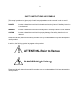
In addition, the following symbol may appear on the product:
ATTENTION–Refer to Manual
DANGER–High Voltage
Please read all safety instructions carefully and make sure you understand them fully before attempting to
use this product.
v
SAFETY WARNINGS AND CLEANING INSTRUCTIONS
DANGER
Opening the cover of this instrument is likely to expose dangerous voltages. Disconnect the
instrument from all voltage sources while it is being opened.
WARNING Using this instrument in a manner not specified by the manufacturer may impair the
protection provided by the instrument.
Cleaning Instructions
To clean the instrument exterior:
! Unplug the instrument from the ac power supply.
! Remove loose dust on the outside of the instrument with a lint-free cloth.
! Remove remaining dirt with a lint-free cloth dampened in a general-purpose detergent and water
solution. Do not use abrasive cleaners.
CAUTION To prevent moisture inside of the instrument during external cleaning, use only enough liquid
to dampen the cloth or applicator.
!
Allow the instrument to dry completely before reconnecting it to the power source.
vi
1
ORTEC MODEL 659
5-kV DETECTOR BIAS SUPPLY
1. DESCRIPTION
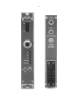
The ORTEC Model 659 5-kV Detector Bias Supply
furnishes bias voltage for germanium detectors,
silicon detectors, or ionization chambers. It can be
used with any detector that draws less than 100 A
of current, and whose gain is insensitive to the
applied voltage. The output voltage is continuously
adjustable from zero to full scale with a calibrated
and locking 5-turn dial. Separate outputs are
provided for the 0-5 kV and the 0-500 V ranges. A
10-segment bar-graph indicator verifies that the
selected voltage is being supplied at the output.
Security against accidentally changing the output
polarity to the wrong state is ensured by two
features. The selected output polarity is indicated
by front-panel LEDs whenever the NIM bin power is
turned on. Thus, the correct polarity can be verified
before the HV ON/OFF switch is used to turn on the
bias voltage to the detector. In addition, the side
panel must be removed in order to alter the output
polarity. This discourages unintentional changes.
the bias voltage and turns on a SHUTDOWN
indicator light. The bias voltage remains off,
independent of the signal from the preamplifier
warmup sensor, until the shutdown mode is
manually canceled by pressing the RESET pushbutton. This protects the preamplifier FET if the
detector is cooling down with the HV ON/OFF
switch accidentally left on. For further protection
against operator error in the ORTEC shutdown
mode, the bias shutdown input interprets a
disconnected cable or a shorted cable as a warm
detector, and responds by turning off the bias
voltage. Some detector manufacturers provide a
TTL logic level output from their detector warmup
sensor. A board-mounted jumper in the Model 659
can be moved to the TTL position to make the bias
shutdown input compatible with detectors supplying
a TTL output. It is also possible to disable the bias
shutdown feature by moving the board jumper to
the BYPASS position. The Model 659 is shipped
from the factory in the ORTEC mode.
The Model 659 includes a remote shutdown feature
to protect the preamplifier FET against damage
when a cooled germanium or Si(Li) detector warms
up. A BIAS SHUTDOWN input that is compatible
with the standard warmup sensor output on ORTEC
preamplifiers is provided. When the preamplifier
signals a warmup condition, the Model 659 shuts off
Both high voltage outputs are protected against
overload. When the bias supply senses an
excessive output current demand, it turns on the
overload light and reduces the output voltage until
the output current is within tolerable limits.
Recovery from overload is automatic when the
excessive current demand is eliminated.
:
2. SPECIFICATIONS1
2.1. PERFORMANCE
BIAS VOLTAGE RANGES 0-5 kV, or 0-500 V, on
separate outputs, with each output controlled by a
common, 5-turn, direct-reading, precision
potentiometer located on the front panel.
BIAS VOLTAGE POLARITY Positive or negative.
Internally selectable. Polarity indicated by frontpanel LEDs whenever bin power is on.
1
Subject to change without notice
:
RATED OUTPUT CURRENT 0-100 A.
OUTPUT LINEARITY Within ±3% of dial setting
from 10% to full range.
TEMPERATURE SENSITIVITY OF OUTPUT
VOLTAGE <±0.08%/°C through 10° to 50°C
operating range.
2
VOLTAGE STABILITY <±0.1%/h variation in
output voltage with constant temperature, constant
load, and constant input voltages from the bin
supply.
NOISE AND RIPPLE <10 mV peak-to-peak from
2 Hz to 50 MHZ.
OUTPUT VOLTAGE RISE TIME Nominally 500
ms.
2.2. INDICATORS
0 kV - 5 kV Front-panel, 10-segment, bar-graph
display indicates actual output voltage at the 0-5 kV
output. Each segment corresponds to a 0.5-kV
increment in output voltage, starting with 0.5 kV to
turn on the first segment, and ending with 5 kV to
turn on the tenth segment.
HV ON/OFF Front-panel toggle switch turns the 0500 V and the 0-5 kV outputs on or off. For added
safety, the RESET push-button must be pressed
after turning the HV ON/OFF switch to the ON
position, in order to turn on the output voltage. The
output voltage will not turn on if a shutdown
condition is present at the BIAS SHUTDOWN input.
RESET Pressing this front-panel push-button
switch enables the high voltage to turn on after the
bin power has been turned on, the HV ON/OFF
switch has been turned on, or the supply has been
disabled by the BIAS SHUTDOWN input. If a
shutdown condition is still present at the BIAS
SHUTDOWN input, the RESET button will be
ineffective.
NEG Front-panel LED is lit when the bin power is
on, if the negative output polarity has been
selected.
ORTEC/TTL/BYPASS Internal printed wiring board
jumper selects the operating mode of the BIAS
SHUTDOWN input for compatibility with the
warmup sensor in the associated Ge detector. The
ORTEC position is used for ORTEC detectors. The
TTL position is for detectors employing TTL levels.
The BYPASS position disables the BIAS
SHUTDOWN input, but does not alter the function
of the RESET button. The Model 659 is shipped
with this jumper in the ORTEC mode.
ON Front-panel LED indicates when the output
bias voltage is turned on. This LED turns off when
the HV ON/OFF switch is turned off, the bin power
is off, or the shutdown mode has been activated.
OUTPUT VOLTAGE POLARITY
The output
polarity is changed between positive and negative
by changing the position of a daughter board in the
module.
POS Front-panel LED is lit when the bin power is
on, if the positive output polarity has been selected.
OVERLOAD Front-panel LED turns on when the
bias supply senses an excessive output current
demanded by the external load. Under overload,
the output voltage is reduced automatically until the
output current is within tolerable limit. Recovery
from overload is automatic when the overload is
eliminated.
SHUTDOWN Front-panel mounted LED turns on
when the shutdown mode has been activated to
turn off the output voltage. The shutdown mode is
activated by the appropriate signal level on the
rear-panel, BIAS SHUTDOWN input, or whenever
the bin power is turned off and on.
2.3. CONTROLS
0-5 kV Front-panel, 5-turn, direct-reading, locking
potentiometer with 500 dial divisions adjusts the
output voltages simultaneously for the 0-500 V and
the 0-5 kV outputs.
2.4. INPUTS
BIAS SHUTDOWN INPUT
Rear-panel BNC
connector accepts signals from warmup sensors in
cooled germanium detectors. When a warmup is
signaled, this input turns off the detector bias
voltage in order to protect the preamplifier FET
input. The ORTEC/TTL/ BYPASS jumper selects
the operating mode of the BIAS SHUTDOWN input
for compatibility with the warmup sensor in the
associated Ge detector.
ORTEC Mode The input is compatible with
the warmup sensor output on ORTEC
germanium detectors. For added safety, an
open or shorted coaxial cable on the BIAS
SHUTDOWN input will also cause the supply
to shut down.
3
TTL Mode A source supplying >+2 V or an
open circuit will allow the Model 659 to
produce the full output voltage. A source
supplying <+0.8 V and capable of sinking 700
A will shut down the high voltage output.
:
S
700 k . A voltage foldback circuit protects the
output against demands for excessive output
current. Recovery from overload is automatic when
the overload is eliminated.
2.6. ELECTRICAL AND MECHANICAL
BYPASS Mode The BIAS SHUTDOWN
input is rendered inactive, and cannot trigger
a bias shutdown.
2.5. OUTPUTS
0-5 kV Rear-panel SHV connector furnishes the
adjusted output voltage in the 0 to 5 kV range
through an output impedance of approximately 2
M . A voltage foldback circuit protects the output
against demands for excessive output current.
Recovery from overload is automatic when the
overload is eliminated.
S
POWER REQUIREMENTS The Model 659 derives
its power from a NIM bin/power supply. Required dc
voltages and currents are: +24 V at 80 mA, +12 V
at 80 mA, -12 V at 65 mA, -24 V at 35 mA.
WEIGHT
Net 0.68 kg ( 1.5 lb).
Shipping 1.1 kg ( 2.5 lb).
DIMENSIONS NIM-standard single-width module
3.43 x 22.13 cm (1.35 x 8.714 in.) front panel per
DOE/ER-0457T.
0-500 V Rear-panel SHV connector furnishes the
adjusted output voltage in the 0 to 500 V range
through an output impedance of approximately
3. INSTALLATION
3.1. GENERAL
3.3. SELECTION OF OUTPUT POLARITY
The Detector Bias Supply is normally used in
conjunction with other modular electronics and is
installed in a Model 4001A/4002A NIM Bin/Power
Supply. The NIM Bin/Power Supply is intended for
rack mounting. Therefore, any other equipment that
may be installed in the same rack must be
sufficiently cooled by circulating air to prevent any
localized heating of the circuits in the Model 659.
The temperature of equipment operating in racks
can easily exceed the recommended maximum of
50°C (120°F) unless these precautions are taken.
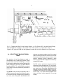
The polarity of the output voltage of the Model 659
is determined by the location of a printed wiring
board that plugs onto the main printed wiring board.
Access to the board is obtained by removing the
right side panel of the module (viewed from the
front). When the polarity PWB is moved to the
forward position, positive polarity is selected. When
the polarity PWB is moved to the rear position,
negative polarity is selected (Fig. 1). The selected
output is indicated by two front-panel-mounted
LEDs. POS indicates positive high voltage and
NEG indicates negative high voltage. The
capacitors on this board can retain substantial
voltages even after power is turned off. Observe
the precautions in Section 3.2 to avoid injury.
3.2. CAUTION
Removal of the module side panel exposes
components that operate at voltages up to 5 kV.
Always turn power Off before removing the side
panel, and connect a grounded wire to each
output.
4
Fig. 1. Changing the High Voltage Output Polarity: (A) For Positive HV, plug the Printed Wiring
Board (PWB) into the leftmost (toward the front of the module) set of pin sockets; (B) For
Negative HV, plug the PWB into the rightmost (toward the rear of the module) set of pin sockets.
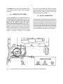
3.4. SELECTION OF BIAS SHUTDOWN
MODE
The selection of the Bias Shutdown mode is
accomplished via a printed wiring board (PWB)
jumper located on the main PWB (Fig. 2). Access
to the jumper is obtained by removing the right side
panel (viewed from the front). Its three alternate
locations ORTEC, TTL, and BYPASS are marked
on the PWB. Follow the precautions prescribed in
Section 3.2.
The ORTEC mode provides compatibility with all
ORTEC detectors having a Bias Shutdown output.
In this mode, the high voltage output is reduced to
zero volts, and a front-panel SHUTDOWN LED
indicates a shutdown condition exists if the coaxial
cable connecting the ORTEC detector to the Bias
Shutdown input becomes open or shorted, or the
detector shutdown circuitry indicates a warm
detector. The Model 659 is shipped from the factory
in the ORTEC mode.
The TTL mode is provided to interface with Bias
Shutdown circuits compatible with TTL logic levels.
In this mode, the high voltage output is reduced to
zero volts, and a front-panel SHUTDOWN LED
indicates a shutdown condition exists it a logic "0"
is applied to the center pin of the Bias Shutdown
input. A logic “1" (or open collector) applied to the
center pin allows normal operation of the high
voltage.
5
The BYPASS mode allows normal operation of the
high voltage output without Bias Shutdown
protection.
connectors. The adjusted high voltage is available
through the output connectors as soon as the Model
659 HV ON/OFF switch is turned ON and the
RESET push button is pressed.
3.5. CONNECTION TO POWER
3.6. OUTPUT CONNECTION
This instrument obtains its dc operating power from
the standard Bin and Power Supply in which it is
installed. Always turn bin power Off and the
Model 659 HV ON/OFF switch OFF before
inserting or removing the module. After insertion,
turn on the bin power, but leave the Model 659 HV
ON/OFF switch in the OFF position. This ensures
that the polarity selection of the Model 659 will be
indicated by an LED on the front panel before high
voltage is actually furnished to its output
The Model 659 5-kV Bias Supply is compatible with
all ORTEC preamplifiers that include provision to
accept the high voltage for the detector. The output
controls are located on the front panel, and the
output connectors are located on the rear panel.
The output cables require a type SHV connector at
the power supply end, which is the type furnished
with each ORTEC preamplifier for that purpose.
Fig. 2. Jumper Positions for Selecting the Proper Bias Shutdown Configuration.
6
4. OPERATION
CAUTION
Always have the high voltage turned off before connecting the cable to or disconnecting
it from the preamplifier.
Make sure the output high voltage setting of the Model 659 does not exceed the safe
limits for the preamplifier or detector to which It is connected.
4.1. SILICON SURFACE-BARRIER
DETECTORS
Operating bias voltage for a silicon surface-barrier
detector should be obtained from the 0 to 500-V
output connector located on the rear panel. The
voltage should not be applied as a large step, but
should instead be advanced gradually from zero up
to the recommended operating potential. With the
Model 659, set the front-panel control at zero before
switching the power On and pressing RESET. Then
gradually advance the setting of the 5-turn
potentiometer to the recommended level for the
detector. It is a good idea to monitor the noise from
the surface-barrier detector as the high voltage is
gradually increased. A rapid increase in noise warns
of impending breakdown in the detector. The noise
should be monitored through the associated
preamplifier and amplifier by observation on an
oscilloscope.
To remove the detector bias, reduce the setting of
the 5-turn control to zero at the Model 659 while the
output cable is still connected to the preamplifier.
4.2. OTHER TYPES OF DETECTORS
Operating bias for germanium detectors can be
applied as a step from zero to the full operating
value. For these applications the 5-turn
potentiometer can be adjusted to the required
output voltage level while the power switch is turned
Off, and then power can be applied by simply
turning the Model 659 HV ON/OFF switch to ON
and pressing the RESET push-button.
4.3. RECOVERY FROM BIAS SHUTDOWN
When the BIAS SHUTDOWN mode is triggered by
the germanium detector's warmup sensor, the HV
ON/OFF switch should be turned OFF. After the
detector has been cooled down long enough to
ensure a safe vacuum in its cryostat, the HV
ON/OFF switch should be turned ON. Usually, it is
necessary to wait well past the time at which the
warmup sensor indicates a cooled detector in order
to ensure a safe vacuum, particularly on older
detectors. Consult the detector manufacturer's
instructions regarding the safe waiting period. Once
the HV ON/OFF switch is ON, pressing the RESET
button restores the bias voltage to the detector and
turns off the SHUTDOWN LED. If the detector is
still signaling a warmup condition, the RESET
button is not able to cancel the shutdown mode.
7
5. CIRCUIT DESCRIPTION
The Model 659 uses a dc-to-dc converter to charge
a Cockcroft-Walton multiplier circuit. The primary of
transformer T1 is driven from the switched-mode
power supply control circuit (U1) operating at
approximately 20 kHz. Transistors Q1 and Q2 are
the switching transistors for transformer T1.
The output voltage is adjusted by controlling the
voltage applied to the primary of the transformer.
Potentiometer R34 controls the primary voltage
through transistors Q7 and Q4.
The circuitry in the transformer secondary consists
of a 7-stage Cockcroft-Walton2 multiplier circuit.
Polarity selection is made with a plug-in printed
wiring board (PWB) that completes the necessary
circuits for either polarity by its orientation on the
main PWB. For polarity reversal, the input and
output terminals of the Cockcroft-Walton circuit are
interchanged.
The 0-500 V output is taken from the first stage of
the multiplier circuit so that this output will always
have the same polarity as the 0-5 kV output.
Calibration of the output voltage is accomplished
with trim pots R30 (HI CAL) and R37 (LOW CAL).
Set the 5-turn output adjust potentiometer (FP) to 5
kV. Adjust R30 for 5 kV at the 0-5 kV output
connector. Set the 5-turn output adjust
potentiometer (FP) to 500 V and adjust R37 for 500
V output at the 0-5 kV output connector. Since
these controls interact with each other, this
adjustment may have to be repeated.
The 10-segment bar-graph display is intended as an
approximate visual indication of the output voltage.
The sampled voltage is derived directly from the
high voltage present at the output connector.
Resistors R29, R33, and R65 form a voltage
divider/calibration network. The calibrated output
reference voltage is input to U2, a unity-gain buffer
amplifier. Amplifier U3 functions as a unity-gain
2
Everhart and Lorrain, "The Cockcroft-Walton Voltage Multiplying
Circuit," Rev. Sci. Instr. 24(3), 221 (1953).
inverting buffer when negative polarity is selected,
and as a unity-gain noninverting buffer when
positive polarity is selected. This configuration
assures that the reference voltage supplied to the
display driver is always positive. The display driver,
U4, senses the output reference voltage and drives
a 10-segment LED bar-graph, providing an analog
display of the high voltage output.
The calibration of the 10-segment bar-graph display
on the front panel is made with trim pot R65
(Display Cal).
Set the 5-turn output adjust potentiometer to 2500
V, and adjust R65 until the 5th segment in the
display just begins to turn on.
Upon initial power-up (the bin supply is turned on),
U5B is latched to a "shutdown" condition by Q12,
R40, and C11, the power-up preset circuitry. In a
shutdown condition, U5 pin 5 is held low inhibiting
the switching output of U1 (and thus the high
voltage output), Q8 is turned Off, and the frontpanel ON LED will not light. U5A provides a
shutdown signal from the remote shutdown circuitry.
Pressing the front-panel RESET push button sets
U5 to a "operate" condition. U5 pin 5 is high,
allowing the switching output of U1 and Q8 to turn
On, causing the front-panel ON LED to light.
If the Bias Shutdown Input circuit is used, it will
latch the output voltage of both of the Model 659
output circuits to zero volts when the external
driving circuit signals that a shutdown condition
exists. Jumper W1, located on the printed wiring
board, selects which type of external bias shutdown
driver circuit is used.
In ORTEC mode, the HV output will be disabled
when the bias shutdown circuitry senses a -24 V to
+5 V transition at the center contact of the Bias
Shutdown connector (-24 V indicates a cold
detector, +5 V indicates a warm detector). The input
source must be capable of driving approximately
1.5 mA. This turns on Q13 and Q1O. With Q1O
turned On, U5A is latched to a "shutdown"
8
condition, signaling U5B to turn the high voltage
Off. Transistor Q15 is turned On, causing the frontpanel Shutdown LED to light. This condition will
remain "latched" until the external circuit indicates
a cold detector condition and the operator pushes
the front-panel RESET push button. U5A is then
preset to an "operate" condition awaiting the next
shutdown signal from the external source.
In TTL mode, the HV output is turned off when the
external circuit supplies a logic "0" to the center
contact of the Bias Shutdown connector. The input
source must be capable of sinking approximately
700 A. This turns on both Q11 and Q9. With Q9
turned On, U5A is latched to a "shutdown"
condition, signaling U5B to turn the high voltage
Off. Transistor Q15 is turned On, causing the frontpanel Shutdown LED to light. This condition will
remain "latched" until the external circuit supplies a
logic "1" to the center contact of the BNC
connector, and the operator pushes the front-panel
:
RESET push button. U5A is then preset to an
"operate" condition awaiting the next shutdown
signal from the external source.
In BYPASS mode, the remote shutdown circuitry is
bypassed, allowing the high voltage supply to
operate without remote shutdown protection.
Overcurrent protection is accomplished by Q5, Q6,
and D16. Diode D16 sets a voltage reference for
Q5. When an overcurrent condition exists, the
voltage drop across R21 becomes sufficient to turn
Q5 and Q6 On. This reduces the duty cycle of the
switching oscillator (thus reducing the output
current) and causes the Overload LED to light.
When the overload condition is removed, Q5 and
Q6 turn Off, returning the switching oscillator to
normal operation and extinguishing the Overload
LED.
6. FACTORY REPAIR SERVICE
This instrument can be returned to the ORTEC
factory for service and repair at a nominal cost. Our
standard procedure for repair ensures the same
quality control and checkout that are used for a new
instrument. Always contact ORTEC Customer
Service, (865) 482-4411, before sending an
instrument for repair to obtain shipping instructions
and so that the required Return Authorization
Number can be assigned to the unit. Write this
number on the address label and on the package to
ensure prompt attention when it reaches the
ORTEC factory.
9
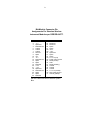
Bin/Module Connector Pin
Assignments For Standard Nuclear
Instrument Modules per DOE/ER-0457T.
Pin
1
2
3
4
5
6
7
8
9
10
11
12
13
14
15
*16
*17
18
19
20
21
22
Function
+3 V
-3V
Spare bus
Reserved bus
Coaxial
Coaxial
Coaxial
200 V dc
Spare
+6 V
-6V
Reserved bus
Spare
Spare
Reserved
+12 V
- 12 V
Spare bus
Reserved bus
Spare
Spare
Reserved
Pin
23
24
25
26
27
*28
*29
30
31
32
*33
*34
35
36
37
38
39
40
*41
*42
G
Function
Reserved
Reserved
Reserved
Spare
Spare
+24 V
- 24 V
Spare bus
Spare
Spare
117 V ac (hot)
Power return ground
Reset (Scaler)
Gate
Reset (Auxiliary)
Coaxial
Coaxial
Coaxial
117 V ac (neutral)
High-quality ground
Ground guide pin
Pins marked (*) are installed and wired in
ORTEC’s 4001A and 4001C Modular System
Bins.