1
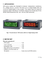
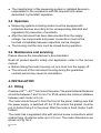
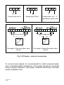
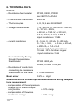
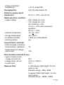
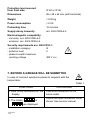
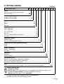
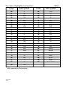
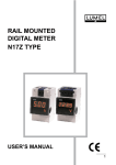
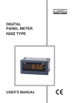
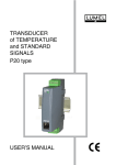
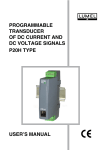
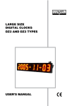
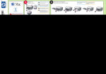
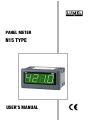
PANEL METER N15 TYPE USER’S MANUAL PANEL METER N15 TYPE Contents: 1. APPLICATION................................................................................. 5 2. METER SET.................................................................................... 5 3. BASIC SAFETY REQUREMENTS................................................. 6 4. INSTALLATION............................................................................... 8 5. SERVICING....................................................................................11 6.TECHNICAL DATA........................................................................ 12 7. BEFORE A DAMAGE WILL BE SUBMITTED.............................. 14 8. OPTION CODES........................................................................... 15 9. MAINTENANCE AND GUARANTEE............................................ 20 1. APPLICATION N15 series meters are intended to measure temperature, resistance, d.c. voltage and d.c. current. The have a 4 or 5-digit display field (14 or 20 mm height digits) in red or green. The meters have an output for supplying object transducers. Protection degree from frontal side: IP 65. Small overall dimensions 96 48 64 mm (with terminals). Fig.1 Frontal view of N15 meter with 4 or 5-digit display field. 2. METER SET The set consists of: – N15 meter................................... 1 pc. – user’s manual............................. 1 pc. – guarantee card........................... 1 pc. – plug with screw connections....... 1 pc. – holders to fix the meter on the panel..................................... 2 pcs (4 pcs, with IP65 version) 3. BASIC SAFETY REQUREMENTS Symbols located in this service manual mean: WARNING! Warning of potentially, hazardous situations. Especially important. One must be aware of with this before connecting the meter. Ignoring the notices marked by these symbols can cause severe injuries and damage of the equipment. CAUTION! Designates a general useful note. Following these instructions make handling the meter easier. One must take note of this when the instrument is working inconsistently to the expectations. Complications may arise if disregarded. In the security scope the meter meets the requirements of the EEC LowVoltage directive (EN 61010-1 issued by CENELEC). Remarks concerning the operator safety: 3.1 General The N15 meter is designed to be mounted on a panel. removal of the required housing, inappropriate use, incorrect installation or operation create the risk of injury to person or damage to the equipment. For more detailed information please see the service manual. All operations concerning transport, installation, and commissioning as well as maintenance must be carried out by qualified, skilled personnel and national regulations for the prevention of accidents must be observed. According to this basic safety information, qualified, skilled personnel are persons who are familiar with the installation, assembly, commissioning, and operation of the product and who have qualifications necessary for their occupation. Non-authorised 3.2 Transport, storage Please observe the notes on transport, storage and appropriate handling. Observe the climatic conditions given in Technical Data. 3.3 Installation The meter must be installed according to the regulation and instructions given in this service manual. Ensure proper handling and avoid mechanical stress. Do not bend any components and do not change any insulation distances. Do not touch any electronic components and contacts. Instruments may contain electrostatically sensitive components, which can easily be damage by inappropriate handling. Do not damage or destroy any electrical components since this might endanger your health! 3.4. Electrical connection Before switching the meter on, one must check the correctness of connection to the network. In case of the protection terminal connection with a separate lead one must remember to connect it before the connection of the instrument to the mains. When working on live instruments, the applicable national regulations for the prevention of accidents must be observed. The electrical installation must be carried out according to the appropriate regulations (cable cross-sections, fuses, PE connection). Additional information can be obtained from the service manual. The documentation contains information about installation in compliance with EMC (shielding, grounding, filters and cables). These notes must be observed for all CE-marked products. The manufacturer of the measuring system or installed devices is responsible for the compliance with the required limit values demanded by the EMC legislation. 3.5 Operation Measuring systems including meters must be equipped with protection devices according to the corresponding standard and regulations for prevention of accidents. After the instrument has been disconnected from the supply voltage, live components and power connections must not be touched immediately because capacitors can be charged. The housing and the door must be closed during operation. 3.6 Maintenance and servicing Please observe the manufacturer’s documentation. Read all product-specific safety and application notes in this service manual Before taking the meter housing out, one must turn the supply off. The removal of the instrument housing during the guarantee contract period may cause its cancellation. 4. INSTALLATION 4.1. Fitting Prepare a 92+0,6 45+0,6 mm hole in the panel. The panel material thickness should be between 1 and 15 mm. For IP 65 version the minimum distance between each meter is 5 mm. The meter should be put in from the front of the panel, making sure that the power supply is switched off. For IP 65 version the gasket must be put on before fixing it to the panel. After the meter is fixed, fasten it with holders. The meter has a separated strip with terminal screw connections which enable fixing of external wires up to 2,5 mm. The meter dimensions are shown on Fig. No.2. Fig.2. The meter overall dimensions 4.2 External connection schemes Description of the terminal strip , connection of input signals and supply are shown in Fig. 3 Resistance thermometer in a two-wire system or potentiometric transmitter Resistance thermometer in a three-wire system Thermocouple Current input mA, A Voltage input 60 mV The supply of two-wire object transducers Voltage input „mV”, „V” according to option code The supply of three-wire object transducers Fig.3 N15 meters - electrical connections. To connect input signals it is recommended to install screened leads, due to electromagnetic interference. The supply should be connected using a double conductor, with proper conductor dimensions and with proper installation fuse. 10 5. SERVICING After connecting external signals and switching on the power, the meter starts to measure automatically and display the measured value. The meter can be reprogrammed with the Manufacturer, in servicing workshops and with distributors. The parameters which can be changed are as follows: - indication range, - indication recounting, - decimal point, - number of averaged measurements, - manual or automatic compensation, the value of manual compensation (only in the temperature meters, concerns the compensation of wire resistance changes or terminal temperature), - unit symbol highlighting (switching on/off). The appearance of the following symbols on the digital display means: Exceeding the upper measuring range or lack of sensor. Exceeding the lower measuring range or sensor short-circuit. 11 6. TECHNICAL DATA INPUTS: – Resistance thermometer Pt100, Pt500, Pt1000 acc IEC 751+A1+A2 – Potentiometer transmitter 4000 – Thermocouples J, K, N, E acc EN 60584-1 – Voltage measurement - 10...60 mV, 0...150 mV, 0...300 mV, 0...10 V, 0...200 V, 60 mV, 150 mV, 300 mV, 2 V, 10 V, 50 V, 200 V input resistance > 1 M – current resistance 0...5 mA, 0...20 mA, 0...200 mA, 0...1 A, 0...5 A, 5 mA, 20 mA, 200 mA, 1 A, 5 A for 1 A and 5 A input resistance 10 m 10% for other ranges: input resistance < 5 – Current intensity flowing through the resistance thermometer Pt100 < 800 A Pt500, Pt1000 < 100 A – Resistance of conductors connecting the resistance thermometer to the meter < 15 /conductor Basic error 0.2% 1 digit Additional errors in rated operational conditions during temperature measurement: - compensation of the temperature change of the thermocouple cold junction 0.2% range - compensation of the wires resistance change 0.2% range 12 - change of ambient temperature (0.1% range/10K) Averaging time min 0.2s (assumptive 1s) Output to supply object transducers 24 V d.c. 10%, max 25 mA Rated operation condition: - supply voltage 230 V 50/60 Hz 10% 110 V 50/60 Hz 10% 24 V 50/60 Hz 10% 12 V d.c. 10% without galvanic insulation 24 V d.c. 10% - ambient temperature - storage temperature - air relative humidity - working position -10...23...55C -25...+85C < 95% (no condensation) any Long duration overload: - thermocouples, resistance thermometers, resistance - measurement of voltage and current 1% 10% Short duration overload (3 sec): - inputs of sensors and voltage up to 60 mV 30 V - voltage input > 60 mV 10 Un (< 1000 V) - current input 10 In Read-out field 4 LED display (digit height: 20 mm) green or red; indication range: -1999...9999 5 segment LED (digit height: 14 mm) red or green; indication range: -19999...19999 13 Protection level ensured from front side IP 50 or IP 65 Dimensions 96 x 48 x 64 mm (with terminals) Weight < 0,25 kg Power consumption < 6 VA Preheating time 15 minutes Supply decay immunity acc. EN 61000-6-2 Electromagnetic compability: - immunity acc. EN 61000-6-2 - emission acc. EN 61000-6-4 Security requirements acc. EN 61010-1: - installation category III - pollution level 2 - phase-to-earth maximum working voltage 300 V a.c. 7. BEFORE A DAMAGE WILL BE SUBMITTED In case of incorrect symptoms please to acquaint with the below table. Table 1 SYMPTOMS PROCEDURE 1. Lack of any indications on the display. 2. The marks: or are displayed 14 Check the connection of the mains cable. Check the input connection correctness. See service manual. 8. OPTION CODES Panel meter N15 Table 2 XX X X X X X X XX X XX ... Input: write the code of the input quantity from the table 3............................................XX Number of displays: 4 digits of 20 mm high..........................................4 5 digits of 14 mm high..........................................5 Display colour: red.............................................................................. R green.......................................................................... G on order *.................................................................... X Supply voltage: 230 V 50/60 Hz.................................................................. 1 110 V 50/60 Hz.................................................................. 2 24 V 50/60 Hz.................................................................... 3 24 V d.c............................................................................. 4 12 V d.c. without galvanic isolation................................... 5 on order *........................................................................... X Supplying output: without output........................................................................... 0 24 V d.c.(maximal load 25 mA)................................................ 1 Protection level through the housing: IP 50................................................................................................0 IP 65................................................................................................1 Kind of terminals: socket - screw plug.................................................................................0 on order **..............................................................................................X Execution: standard.......................................................................................................00 custom made*............................................................................................. XX Acceptance tests: without an extra quality inspection certificate...................................................... 8 with an extra quality inspection certificate........................................................... 7 according customer’s agreement*...................................................................... X NOTE Unit: (only in the execution with 5 digits). The code number according table 4.................XX When ordering give: - measuring range, - sensor type (concerning the input to co-operate with a thermocouple, e.g. J), - choice of compensation (concerns temperature meters): manual (give the value C, ), automatic ... * The code number must be agreed with the manufacturer ** Possible execution with self-locking sockets. 15 Table 3 Input Code Pt100 (-200...850C) Pt100 (-50...150C) Pt100 (-50...250C) Pt100 (-50...400C) Pt100 (-50...600C) Pt500 (-200...850C) Pt1000 (-200...850C) Potentiometer transmitter 4000 Thermocouple J,K,N,E, -10...60 mV 0...150 mV 0...300 mV 0...10 V 0...200 V 60 mV 150 mV 300 mV 2 V 10 V 50 V 200 V 0...5 mA 0...20 mA 0...200 mA 0...1 A 0...5 A 5 mA 20 mA 200 mA 1 A 5 A 00 01 02 03 04 05 06 07 08 09 10 11 12 13 14 15 16 17 18 19 20 21 22 23 24 25 26 27 28 29 0...100 30 230 V 31 16 0...20 mA (characteristic narrowed down) 32 0...250 V 33 0...150 34 0...1 mA 35 0...20 V 36 0... 1 V 37 0...60 mV 38 4...20 mA 39 0...300 V 40 0...2 V 41 0... 50 V 42 on order* XX *the code number must be agreed with the manufacturer 17 The code of highlighted unit symboli Table 4 Code Unit symbol Code Unit symbol 00 01 02 03 04 05 06 07 08 09 10 11 12 13 14 15 16 17 18 19 20 21 22 23 V A mV kV MV mA kA MA C F K Hz kHz Ah kAh m/s m mm cm m km l l/s l/h 24 25 26 27 28 29 30 31 32 33 34 35 36 37 38 39 40 41 42 43 44 45 XX ms s h N kN Pa hPa kPa MPa bar rad k % rev rev/s rev/m rev/h m/h km/h imp on order * * after agreeing by the producer 18 To avoid any mistake when ordering, please respect our coding procedure. Ordering example: Code: N15 08 5 G 1 0 1 0 00 8 08 0... 450°C, J, comp. auto means: N15 08 5 G 1 0 1 0 00 8 08 - N15 digital meter - thermocouple J input - 5 LED digit displays (digit height = 14 mm) - green colour displays - supply: 230 V 50/60 Hz - without output to supply object transducers - protection degree from frontal side: IP 65 - socket - screw-plug terminals - standard execution - without an extra quality inspection certificate - unit: C Programmed measuring range: thermocouple J = 0... 450°C Automatic compensation of cold junction temperature changes, programmed by the manufacturer. Code: N15 01 4 R 1 1 0 0 00 8 08 0... 100°C, comp. auto means: N15 01 4 R 1 1 0 0 00 8 08 0... 100 - N15 digital meter - Pt100 resistance thermometer input (-50... 150C) - four LED digit displays (digit height = 20 mm) - red colour displays - supply: 230 V 50/60 Hz - output to supply object transducers: 24 V d.c. (maximal load = 25 mA), for supplying object transducers - protection level through the housing: IP 50 - socket - screw-plug terminals - standard execution - without an extra quality inspection certificate - unit: C - programmed indication range: 0...100 Automatic compensation of wire resistance, programmed by the manufacturer. 19 – In case of custom-made execution or to obtain more detailed technical information please contact our Export Department. – In case of meter’s damage or break-down please contact the nearest service workshop. 9. MAINTENANCE AND GUARANTEE The N15 meter does not require any periodical maintenance. In case of some incorrect unit operations: 9.1. From the shipping date, during the period given in the annexed guarantee card One should take meter down from the installation and return it to the Manufacturer’s Quality Control Dept. If the unit has been used in compliance with the instructions, the Manufacturer guarantees to repair it free of charge. 9.2. After the guarantee period: One should turn over the meter to repair in a certified service workshop. The disassembling of the housing causes the cancellation of the granted guarantee. 20 21 22 23 SALES PROGRAMME MEASUREMENT DIGITAL PANEL METERS CONTROL BARGRAPH INDICATORS RECORDING MEASURING TRANSDUCERS ANALOGUE PANEL METERS (DIN INSTRUMENTS) DIGITAL CLAMP-ON METERS PROCESS and HOUSEHOLD CONTROLLERS CHART and SCREEN RECORDERS POWER CONTROL UNITS and FREQUENCY INVERTERS AUTOMOTIVE DASHBOARD INDICATORS STATIONARY and PORTABLE CALIBRATORS MEASUREMENT ACCESSORIES (SHUNTS, SENSORS, TRANSFORMERS) MEASURING SYSTEMS (ENERGY, HEAT, CONTROL, MEASUREMENT) CUSTOM-MADE PRODUCTS WE ALSO OFFER OUR SERVICES IN THE PRODUCTION OF: ALUMINIUM ALLOY PRESSURE CASTINGS PRESSURE CASTING DIES AND INJECTION MOULDS PRECISION ENGINEERING AND THERMOPLASTICS PARTS QUALITY PROCEDURES: According ISO 9001 international requirements. All our instruments have CE mark. For more information, please write to or phone our Export Department. Lubuskie Zak³ady Aparatów Elektrycznych LUMEL S.A. ul. Sulechowska 1, 65-022 Zielona Góra, Poland Export Department: Tel.: (48-68) 3295 302 Fax: (48-68) 3254 091 e-mail: [email protected] N15-07A Tel.: (48-68) 3295 100 (exchange) Fax: (48-68) 3295 101 e-mail:[email protected] http://www.lumel.com.pl