1
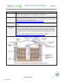
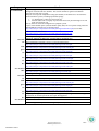
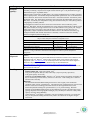
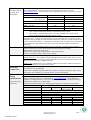
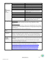
CRICOS No. 00213J CRICOS No. 00213J CRICOS No. 00213J CRICOS No. 00213J CRICOS No. 00213J CRICOS No. 00213J CRICOS No. 00213J CRICOS No. 00213J CRICOS No. 00213J CRICOS No. 00213J Events At special events which will be held twice a year, it is anticipated that up to 150 people will be on site and as such portaloos will be arranged for the comfort of everyone on the property. Viking Rentals http://www.vikingrentals.com.au/toilet-hire-weddings-events.html are a professional portable toilet hire company servicing the Greater Brisbane area. They supply dignified, stylish toilets that are appropriate for any function or special event. Their roomy toilets have a unique and highly effective ventilation system and a large sink with a foot pump. Biolytix Waste Treatment System The Biolytix System is a robust, organic wet soil ecosystem in a tank and is home to worms, beetles and billions of microscopic organisms. It recycles sewage and wastewater into irrigation water for the garden using minimal fossil fuels and no chemicals. It can also recycle all food scraps (with an in sink grinder) and break down non-plastic sanitary items. The difference between Biolytix system and other treatment systems are: Biolytix System 1 service per year Power costs less than $20 per year Silent operation Natural process, no chemicals Safe for people, pets and soil No odour Small tank Continue to treat during power failure Handles peak and throughs in loading Loves organic loads such as milk down the sink Handles a large range of household cleaners You can shower and wash when you want Able to enjoy to the convenience of an In-Sink-Erator for kitchen waste Other Treatment System 4 services per year Power costs more than $130 p/y Uses noisy blowers Rely on chlorine Pathogens may potentially be sprayed around Smells after a very high loading Very large tanks Stop working during power failure Can fail after holidays or during a party Food down the sink can lead to failure Often need to use strict list of cleaners Often need to spread out water usage – family planning needed Can’t handle the extra load of In-SinkErators Based on the anticipated number of people on the property and its weekly waste flow rate, it has been recommended that we install the Biolytix Filter Model BF6 on site. Attached are the Biolytix waste treatment specifications and subsurface drop irrigation guidelines. Level 3, D Block, Gardens Point Campus, 4000 CRICOS No. 00213J Tel: 07 3138 2466 Fax: 07 3138 4438 How The Biolytix® Waste Treatment System Works The Biolytix® Filter is a robust, organic soil ecosystem that converts sewage, wastewater, sanitary items and food wastes into irrigation water. All the wastes are simply fed onto the Biolytix® Filter bed using standard plumbing. The top layer is made up of coarse mesh bags with plastic media in them. This houses the wet soil ecosystem. It accommodates worms, beetles and billions of microscopic organisms. These soil creatures are vital “macerator” organisms, breaking up the organic material, converting the waste into humus and structuring it so that its drainage and air porosity are continually renewed and mainWDLQHGLQGHÀQLWHO\ The organic matter particles then wash through and accumulate on the surface RIDÀQHO\VWUXFWXUHGKXPXVDQGFRFRSHDWOD\HU+HUHLWLVUHSURFHVVHGDJDLQ DQGDJDLQDQGVWUXFWXUHGLQWRDVSRQJHOLNHÀOWHUE\WKHVRLORUJDQLVPVWKDWOLYH in it. 7KHÀQHVWUXFWXUHGFRPSRVWKDVUHPDUNDEOHSURSHUWLHV,WLVZDWHUE\ZHLJKW yet has a high cation and anion exchange capacity. This means it adsorbs and holds back nutrients, chemical compounds and toxins for the trillions of living organisms to digest over time. (Competing treatment processes don’t have this ability.) It also has powerful odour-absorbing capacity, which is why we can guarantee no odours. ® Biolytix® Technologies TFToll FreeZZZELRO\WL[FRP CRICOS No. 00213J Cross Section of a typical Biolytix® Filter (BF6) Sewage entering the top section of the Biolytix® Filter $IWHU WKH ODVW OD\HU WKH HIÁXHQW KDV EHHQ ZHOO WUHDWHG DQG D JHRIDEULF ÀOWHU DERXWWKHGLDPHWHURIWKHWDQNÀOWHUVRXWDOOSDUWLFOHVODUJHUWKDQPLFURQ7KLV WKUHHGLPHQVLRQDOÀOWHULVELRORJLFDOO\FOHDQHGDQGGRHVQRWQHHGDQ\PDLQWHnance. It protects the irrigation system from clogging up. 7KHZDWHUFRPSRQHQWRIWKHZDVWHZDWHUÀQDOO\DFFXPXODWHVLQWKHVXPSZKHUH VRPHPRUHRIWKHYHU\ÀQHVHGLPHQWLVVHWWOHGRXWLQDTXLHVFHQW]RQHEHIRUHWKH clear, reclaimed water can be pumped or drained to irrigation or reuse. $VWKHWHFKQRORJ\LVIXOO\DHURELFLWGRHVQRWUHTXLUHDQHQHUJ\LQWHQVLYHDTXDWLF or odourous septic stage. The layered, flexible modular filter elements are GHVLJQHGWRDOVREHLQVWDOOHGLQWRDFRQYHQWLRQDOVHSWLFWDQNXQLWEXWDUHHTXDOO\ suited to be used within any vertical cylindrical tank (normally a minimum depth RIDSSUR[LPDWHO\PLVUHTXLUHG 1RUPDOO\WKHÀOWHULVFRQVWUXFWHGZLWKLQDVWDQGDUGOLWUHSRO\PHUWDQNP GLDPHWHU E\ P KLJK 7KH RQO\ PHFKDQLFDO FRPSRQHQWV LQ WKH VWDQGDUG WUHDWPHQWXQLW%)ÀOWHUDUHDVLQJOHSKDVHLQGXVWULDOVWUHQJWKSXPSDQGDWLQ\ EXWUREXVWZDWWDLUSXPS The Biolytix® Filter can be scaled according to the wastewater loading. ® Biolytix® Technologies TFToll FreeZZZELRO\WL[FRP CRICOS No. 00213J BIOLYTIX® FILTER BF6 Category Model: Specification Details Manufacturer: Versions Bed Configuration: Biolytix® Filter Model BF6 (or “Deluxe Model”) Biolytix® Filter Model BF6UV (when supplied with UV disinfection) On-site wastewater treatment system. Treats domestic wastewater to a high secondary standard. Biolytix® Water Pty Ltd A Biolytix® Brochure “Information Kit” that provides general information on Biolytix® and the Biolytix® Filter range may be downloaded from: http://docs.biolytix.com/sales/record/SR_InfoKit%28web%29.pdf The Filter may be configured to suit project specific requirements. Variables include: pump or gravity discharge, tank size (to suit inlet sewer invert), pump type, tank type (factory supplied or retrofit). Central pump well with sealed lid (pumped version only). Base level sump of bagged open plastic structural support material to a depth of approximately 300 mm. Filter bed of three layers each consisting of a geotextile support cloth under bagged structurally supported humus/peat and bagged open plastic support material to provide a total bed depth of 1050 mm (including base level sump). Refer Figure 1 for typical cross-section of Filter. A general arrangement drawing of Biolytix® BF6 Filter may be downloaded at: http://docs.biolytix.com/products/record/drawings/BF6/BF6_01.PDF Figure 1: Cross Section of Biolytix® Filter BF6 (Pumped Discharge Version) Biolytix Water Pty Ltd PR-BF6Specifications R-7 CRICOS No. 00213J 1of 6 Category Certification: Australia NT NSW QLD SA Tas Vic WA New Zealand ARC Australia NT NSW QLD SA Tas Vic WA New Zealand Details Regulatory approval requirements for installation of a Biolytix® BF6 and BF6UV vary throughout Australia and New Zealand. This section summarises general accreditation approvals for each state or region. Pumped version passed independent testing (SAI Global) to AS/NZS 1546.3 for alternative aerated treatment systems, including operational options: 1. UV disinfection at a dose rate of 88 mWs/cm2 2. Influent loaded with 2.4 kg/day of putrescible food waste passed through an in-sink food waste disposal unit. Gravity Filter has same bed configuration as pumped systems. Copies of SAI Global reports (include effluent quality data) for two separate testing trials and StandardsMark Certificate may be obtained from: http://docs.biolytix.com/products/record/PR_BF6ApprovalWithUV.pdf (covers filter with/without UV disinfection) http://docs.biolytix.com/products/record/PR_BF6JASANZReport.pdf http://docs.biolytix.com/products/record/BF6_JASANZ_ReportUV.pdf Filter Operation Approvals – BF6 Filter with no disinfection Approval Authority & Reference/ webpage link to document copy Dept of Health & Community Services: Approval Number 08/07 http://docs.biolytix.com/products/record/PR_BF6ApprovalForNT.pdf Dept. of Health: WCT 023 http://docs.biolytix.com/products/record/PR_BF6ApprovalForNSW.pdf Dept. of Infrastructure & Planning: Chief Executive Approval No. 04/2007 http://docs.biolytix.com/products/record/PR_BF6ApprovalForQld.pdf Dept. of Human Services: WCS 01586, 16/12/2003 http://docs.biolytix.com/products/record/PR_BF6ApprovalForSA.pdf Dept. of Justice: Accreditation BSR 0438/2006 http://docs.biolytix.com/products/record/PR_BF6ApprovalForTAS.pdf EPA Victoria:CA90/04 http://docs.biolytix.com/products/record/PR_BF6ApprovalForVic.pdf WA Health: Approval No 169 http://docs.biolytix.com/products/record/PR_BF6ApprovalForWA.pdf ARC letter 13 April 2006. http://docs.biolytix.com/products/record/PR_BF6ApprovalARC.pdf Filter Operation Approvals – BF6 Filter with UV Disinfection (BF6UV) Project specific approval by NT Dept. of Health required. Dept. of Health: BF-002 http://docs.biolytix.com/products/record/PR_BF6ApprovalForNSW.pdf Dept. of Infrastructure & Planning: Chief Executive Approval No. 04/2007 http://docs.biolytix.com/products/record/PR_BF6ApprovalForQld.pdf Dept. of Health: WCS 02077 13/4/2006 http://docs.biolytix.com/products/record/PR_BF6ApprovalForSA.pdf Application pending Project specific approval by Council required. Supplementary fittings or attachments (e.g. UV disinfection) to certified systems do not require EPA approval. Application pending No formal approvals in place. Contact regulatory authority for requirements. Biolytix Water Pty Ltd PR-BF6Specifications R-7 CRICOS No. 00213J 2of 6 Category Effluent quality: On-site dispersal: Loading: Details Secondary standard effluent quality as defined by AS/NZS1547 – “Effluent quality following secondary treatment is expected to be equal or better than 20 g/m3 5-day biochemical oxygen demand and 30 g/m3 suspended solids”. Effluent quality produced by the BF6 Filter is to a higher standard than the secondary standard effluent quality limits. SAI Global completed independent performance tests to AS/NZS1546.3 On-site Domestic Wastewater Treatment Units Part 3: Aerated Wastewater Treatment Systems September 2003. The Table below summarises the results from the independent testing on the BF6 Filter. Essentially the independent testing showed that the Biolytix® Filter (BF6) produces a high quality secondary effluent. No detailed mass balance has been carried out on the nutrient removal efficiency of the Biolytix® BF6 Filter. Based on independent test results from Environment Bay of Plenty on the BF6 Filter module, the average nutrient levels in the final effluent were typically TN: 42mg/L (NH3 approx 30%, NOx approx 70%) and TP 8mg/L. Nutrient levels may however vary significantly subject to hydraulic load and the nutrient level in the influent wastewater (e.g. strength of influent and whether insinkerator is installed). Greater N removal is normally achieved at higher hydraulic loading rates. BF6 Filter Effluent Quality 90 percentile data from AS1546.3 independent tests Standard Putrescible food waste Biochemical Oxygen Demand -BOD5 12 mg/L 15 mg/L Total suspended solids 9 mg/L 10 mg/L Thermotolerant Coliforms <10 cfu/100mL* < 10 cfu/100mL* * Thermotolerant Coliforms only applicable with UV disinfection. The Biolytix® Filter normally achieves 3-4 log reduction in Thermotolerant Coliforms without separate disinfection equipment. Dispersal is to be in accordance with regulatory requirements, typical requirements are as follows: Subsurface drip irrigation or trenches/beds/mounds installed to AS/NZS 1547 if effluent is not disinfected with UV. Biolytix® supplies IWT Netafim Safety Flow dripline and irrigation equipment (refer www.kisss.net.au) as standard option for subsurface and subsoil irrigation. Subsurface drip irrigation guidelines document may be downloaded from: http://docs.biolytix.com/products/procedure/PP_BiolytixDripIrrigationGuidelines.pdf Surface or subsurface irrigation installed to AS/NZS 1547 with UV disinfection at a dose rate not less than 88 mWs/cm2. Hydraulic: Standard Filter bed – Filter bed volume 1.6m3 Long Term Acceptance Rate (LTAR) 1600 L/day (10 person per day equivalent). 4-day peak capacity 2150 L/day Concrete or Non-standard tank – Requires 1 m3 of bed volume per kilolitre of influent per day or 660 mm/day internal surface, whichever is the lesser. Peak loading rate is 880 mm internal surface area/day. Biological: The maximum allowable BOD loading for the Filter varies slightly with certification conditions (refer section “Certification”). The Filter has been comprehensively tested to treat domestic wastewater including putrescible food wastes (through Insinkerator) at the maximum hydraulic loading rates specified above (i.e. 10 person loading). Based on normally accepted BOD loading figures of 60 g.BOD/person per day and putrescible waste (garbage disposal) increasing organic loading by 33%, the Biolytix® Filter has a daily BOD capacity of at least 800 g.BOD/day. Contact Biolytix® if the Filter is required to treat non-standard wastewater (e.g. blackwater only) as the hydraulic loading maximum may need to be reduced to suit higher strength wastewater. Biolytix Water Pty Ltd PR-BF6Specifications R-7 CRICOS No. 00213J 3of 6 Tank Details: Standard Tanks & Existing Tank Retrofit Kits Level Control: Alarm: Electrical control box: Pump cycle: Pump specifications: (Pump discharge Filter only) Standard: The standard Biolytix® Filter is installed in an Everhard polymer septic tank (refer www.everhard.com.au). The Filter may also be supplied in other tanks (e.g. concrete) certified to AS/NZS 1546.1 . Everhard Tank (size) 3000 40001 Height (m): excl. control box 1.90 2.36 incl. control box 2.06 2.51 Diameter (m): 1.88 1.88 Inlet Sewer Invert Depth (m) 0.65 1.1 Mass: Dry (kg) 396 440 Wet2 (kg) 970 1014 1. The 4000 size Filters have the same bed configuration as the 3000 Filter except that the tank is deeper and therefore the bed is located deeper in the ground. 2. Wet weight is with moist filter media, but with no standing water in Filter sump. Filters would normally be delivered with dry weight. Retrofit: The Biolytix® Filter bed may be retrofitted into an existing Australian Standard compliant septic. Typically the tank should be vertical cylindrical with a central access hatch, although it may be possible to retrofit into other tank shapes. Biolytix® provides retrofit kits for various circular tank diameters. A minimum 1.6 m diameter tank is required, and a minimum of 1.1m tank depth is required below inlet sewer to provide sufficient depth for installation of Filter bed. Treated effluent either discharges under gravity or is pumped. In pumped option, effluent is stored in the base layer of each Filter module until float controls are initiated. Standard float switch with swivel mount Open circuit typical setting: 60mm represents 120 l left in storage Closed circuit typical setting: 170mm 340 l in storage Various options are available including: Standard Telemetry: Event Monita (or equivalent) phone line telemetry alarm direct to service provider. Operates on any analogue/ digital telephone system and is certified for operation with the ACA on the Australian Telephone Network. Audio/ Visual: Standard AS 1546.3 compliant audible and visual alarm. Different options are available, including siren or panel mount systems. IP56 polycarbonate weatherproof control box and isolation switch. All components to AS3000:2000. Control box is normally mounted on BF6 Filter module as standard. Wall/ post mount control box option is also available (e.g. for areas that may be prone to flooding). Adjustable range 160-220 litres. Biolytix® normally supplies Pedrollo Pumps in the Sumo and Top ranges. Full specification details of Pedrollo pumps may be obtained from: www.pedrollo.com. The standard pump supplied is a Pedrollo Sumo 2/5, however a Pedrollo Sumo 2/7 or other suitable borehole type pump may be installed to suit required duty. General specification details of the standard pumps supplied, is summarised in table below. Pedrollo Spa Manufacturer: Top 2 Top 3 Sumo 2/5 Sumo 2/7 Model: (BF6 default) 240 volts AC/ Single Voltage/Phase: Yes Thermal protection: Double oil lubricated mechanical Seals: 6m 20m Submersion (max) 9m 10.5m 36m 60m Head (max) 20l/min@8m 20l/min@10m 10l/min@35m 10l/min@58m Duty 1 140l/min@4m 200l/min @ 4m 80 l/min @14m 80 l/min @ 18m Duty 2 0.37kW 0.50kW 0.45kW 0.75kW Power: 3,000 hours 10,000 hours Estimated life: Biolytix Water Pty Ltd PR-BF6Specifications R-7 CRICOS No. 00213J 4of 6 Air Pump Specifications UV Disinfection Unit (Optional) Energy Usage Maximum Noise Schego Manufacturer: M2K3 (membrane pump) Model: 220-240 V/50Hz/single 5 watt Voltage/phase/power: 3m Maximum delivery head: 350 l/hr Flow rate: Diaphragm = 4 years/ Coil = 20 years Estimated life: Refer Schego website for further details: http://www.schego.de UV disinfection unit needs to be ordered separately to the Biolytix® Filter. Various, selected to provide a minimum dose rate of Models: 88mWs/cm2 at the design flow rate for the land application system. 316SS Chamber Material: Selected to suit UV dose. Peak Flow (BF6 effluent): 75 Watt minimum at 12L/min. UV Lamp Wattage: Selected at 9000 hrs minimum (1 year) UV Rated Lamp Life 220/240 VAC, 50Hz Voltage: IP21 Protection Class: Mounted in accordance with manufacturer’s Installation installation instructions, either on top of Biolytix® Filter or remote from Filter, subject to site requirements. Treatment Process: Air Pump. Air pump operates continuously (5 watts), using 0.120 kWhr/day. A Filter operating at a full capacity (1600 L/day) would have an energy usage of 0.075 kWhrs/kL treated. Final Effluent Discharge: BF6 Transfer Pump (pump units only). Energy use for a pumped BF6 Filter varies with pump selection, hydraulic load and discharge pipework design. A Filter fitted with a Sumo 2/5 pump discharging to subsurface drip irrigation will typically have an energy usage in the range 0.3-0.8 kWhrs/kL treated. A gravity discharge BF6 Filter requires no additional energy. Complies with AS 1546.1 < 40 dB(A) @1m fast response Operating conditions: Operates under normal temperature and humidity conditions experienced in Australia and New Zealand (if winter temperatures regularly drop below – 8oC then site ground temperature, soil conditions and hydrology assessment is required to determine if thermal ground insulation is warranted). A cold climate add-on kit is currently under development to enhance performance of treatment system in cold climate regions (e.g. in Tasmania defined as above 900m AHD) Emergency storage capacity: 1,340 litres above high level float cut-in level and below the top filter layer (maintains a dry refuge for filter organisms to survive). If flooding exceeds this level, the filter bed may need reinoculation. The emergency storage typically allows a response time of more than 2 days at a typical domestic household loading rate of 600 L/day. Installation The Biolytix® Filter modules are designed typically for in-ground installation. If the Filter is to be installed above ground, the external walls of the tank are to be UV protected. A detailed copy of the Biolytix® Filter installation manuals may be downloaded from: http://docs.biolytix.com/installation/procedure/IP_BiolytixFilterInstallationManual.pdf Electrical Installation manual: http://docs.biolytix.com/installation/procedure/IP_ElectricalInstallationProcedure.pdf Telemetry Connection manual: http://docs.biolytix.com/installation/procedure/IP_TelemetryConnectionManual.pdf Retrofit kits are to be installed by a trained Biolytix® Installer. Biolytix Water Pty Ltd PR-BF6Specifications R-7 CRICOS No. 00213J 5of 6 Servicing Requirements: Servicing procedures are detailed in the Biolytix® Instruction & Service Manual. A copy of the manual may be downloaded from: http://docs.biolytix.com/service/procedure/VP_BiolytixServiceManual.pdf The Biolytix® Filters require an annual service and system check that includes: • Monitoring and maintenance of humus levels; • Testing effluent quality compliance; • Integrity check for pump, switches, alarm; • Checking biology of the Filter bed; • Flushing irrigation lines and irrigation filter; • Reporting on system performance. UV Lamp (if installed) • Quartz sleeve cleaned 6-monthly. • UV lamp replaced every 12 months. Operators Manual A copy of the operator’s manual may be downloaded from: http://docs.biolytix.com/service/record/VR_OperatorsManual.pdf Warranty: A 12-month warranty is provided free of charge with the purchase of a Biolytix® Filter, guaranteeing the performance, and all components for that period. The Biolytix® Performance Warranty for the Biolytix® Filter is also available after that period for up to 20 years consecutively. Annual fees apply depending on the Filter model, and this includes the abovementioned annual service. The serviceable life of the treatment system is equal to the tank life – typically 20+ years. A copy of Biolytix® Performance Warranty may be downloaded from: http://docs.biolytix.com/service/form/VF_PerformanceWarranty.pdf The table below provides a simplified outline of the Filter naming convention that covers the most popular Filter range. Biolytix® Filter Naming Convention Document (PPFilterNamingConvention) should be referenced to specify special filter configurations (e.g. with a pump different to a Sumo 2/5 or to be supplied as a retrofit kit). Model Tank Size Pump/ Gravity Air Pump Telemetry or Audio Discharge Visual Alarm * BF6 3000 P A T 4000 G V * When filter is supplied with UV disinfection the model is denoted as BF6UV. Examples: BF6-3000-PAT: BF6 Filter with 3000 litre Everhard tank, Sumo 2/5 pump discharge, Schego air pump and phone line telemetry alarm. BF6UV-3000-PAT: BF6 Filter with UV disinfection, 3000 litre Everhard tank, Sumo 2/5 pump discharge, Schego air pump and phone line telemetry alarm. BF6-4000-GAV: BF6 Filter with 4000 litre Everhard tank, gravity discharge, Schego air pump and audio visual alarm system. BF6-4000-PAT: BF6 Filter with 4000 litre Everhard tank, Sumo 2/5 pump discharge, Schego air pump and phone line telemetry alarm system. BF6-4000-PAV: BF6 Filter with 4000 litre Everhard tank, Sumo 2/5 pump discharge, Schego air pump and audio visual alarm system. Product Specification / Naming Convention Details Biolytix Water Pty Ltd PR-BF6Specifications R-7 CRICOS No. 00213J 6of 6 Biolytix Technologies SUBSURFACE DRIP IRRIGATION Biolytix Filter (Bf6) July 2005 CRICOS No. 00213J Biolytix Technologies Pty Ltd ACN 097 798 966 Head Office PO Box 591 Maleny, QLD, Australia 4552 Biowater Projects: 429 Sandy Bay Road, Hobart, Tas, Australia 7005 PH: FAX: Email: PH: FAX: Email: 07 5435 2700 07 5435 2701 [email protected] 03 6225 0730 03 6225 4354 [email protected] Document Status Rev Status Author Reviewer Name Signature Approved for Issue Name Signature Date A First Issue GRI D Cameron J Jordan 11/6/04 B Second Issue GRI D Cameron J Jordan 29/6/04 C IWT dripline option GRI D Cameron J Jordan 3/6/05 CRICOS No. 00213J TABLE OF CONTENTS 1. Introduction............................................................................................................1 1.1. General...........................................................................................................1 1.2. Biolytix Filter.................................................................................................1 1.2.1. Effluent Quality .....................................................................................1 1.2.2. Pumping System ....................................................................................1 1.3. Safety Flow Dripline......................................................................................2 2. Design ....................................................................................................................3 2.1. General Concept.............................................................................................3 2.2. System Components.......................................................................................4 2.3. AS1547 Design Guide ...................................................................................5 3. Construction details ...............................................................................................6 4. References..............................................................................................................6 Appendices Appendix A. Biolytix Filter Pump System Curve...................................................7 Appendix B. Safety Flow Specification ..................................................................8 Appendix C. Standard Irrigation Kit Details...........................................................9 Appendix D. Details of Irrigation Kit Extras ........................................................10 Appendix E. Alternative design approach to AS 1547:2000 ................................12 Appendix F. Subsurface Drip Irrigation Design Form .........................................13 Appendix G. Dripline Selection Tables.................................................................17 Appendix H. Irrigation Area Selection Guide .......................................................23 Appendix I. Multi-Zone Irrigation Layout Drawings ..............................................24 Appendix J. Subsurface Dripline Construction Details ...........................................26 Doc Number Rev C CRICOS No. 00213J Biolytix Technologies Subsurface Drip Irrigation Biolytix Filter (BF6) 1. INTRODUCTION 1.1. General The Biolytix Filter – BF6 produces a wastewater effluent quality suitable for direct subsurface drip irrigation. This document provides general information to assist with the design and installation of a subsurface drip irrigation system suitable for use with a Biolytix Filter – BF6, pumped version (i.e. BF6-PAT or BF6PAV). Biolytix provides irrigation kits using Irrigation and Water Technologies (IWT) patented Safety Flow Irrigation dripline and this manual is based on the use of this dripline. Alternative driplines may require a different design approach. The Safety Flow dripline utilizes Netafim Uniram pressure compensating dripline and references and extracts are taken from Netafim and IWT design guides and specifications wherever possible. 1.2. Biolytix Filter Two parameters of the Biolytix Filter, BF6 affect the operation of a subsurface drip irrigation system, the pumping system and effluent quality. These parameters are discussed below. 1.2.1. Effluent Quality Australian Standard, AS/NZS 1547:2000: On site domestic-wastewater management includes design and construction details for an on-site subsurface drip irrigation system. AS1547 recommends optimum performance may be obtained from a subsurface drip irrigation system if high quality secondary treated effluent having BOD5 (5-day Biochemical Oxygen Demand) and SS (Suspended Solids) levels of 15/15 mg/L. Table 1 summarises the effluent characteristics of the Biolytix Filter BF6 that were achieved when the filter was independently tested by SAI Global to AS/NZS 1546.3:2001. The test results confirm that the Biolytix Filter produces an effluent quality ideal for subsurface drip irrigation. Table 1: Effluent Characteristics from BF6 Filter Characteristic BOD5 Suspended Solids 1.2.2. Results 100% < 20 mg/L 90% < 11.6 mg/L All < 30mg/L 90% < 8.9 mg/L Maximum 14 mg/L Average 8.7 mg/L 14 mg/L 5.4 mg/L Pumping System Treated effluent is stored at the base of the Biolytix™ Filter. The Biolytix™ Filter contains a multistage submersible pump capable of pumping 10L/min at 35 metres and 75 L/min at 15m. A copy of the pump system curve is contained in Appendix A (may be used to design an irrigation system from first principles). The pump operates automatically by float switch when the stored volume reaches approximately 340 litres and stops when the storage is depleted to approximately 120 litres. The effective 220 litre storage volume complies with AS1547 recommendations of 200 litres minimum storage for a drip irrigation pump system. Doc Number Rev C CRICOS No. 00213J Biolytix Technologies Subsurface Drip Irrigation Biolytix Filter (BF6) 1 The BF6 filter pump is ideally suited for direct sub-surface irrigation (pulsed drip). Pulsed subsurface drip irrigation is effective at removing nutrients as well as bacterial and viral pathogens so disinfection of the effluent or nutrient removal prior to irrigation should not normally be necessary. 1.3. Safety Flow Dripline Safety Flow Dripline was invented by Australian company, IWT. Safety Flow is a subsurface drip irrigation system that uses a geotextile to spread the water in both a horizontal and lateral wetting pattern. In one configuration it uses an impermeable layer of polyethylene to minimise the movement of water downwards by gravity allowing the soil to make full use of the water in capillary action. It has a drip line (Netafim) delivering the water to the geotextile, and the base polyethylene layer, at a consistent and predetermined rate. The flow rates and emitter spacing can be adjusted to soil conditions and length of run. The dripline creates an elliptical wetting pattern along the whole length of the material. A Safety Flow product specification is included in Appendix B. Safety Flow is the first sub surface irrigation system, which uses precision capillary irrigation to better manage: x x Gravitational water loss by using steady state irrigation technology. Saline soil conditions by displacing and diluting salts through precise applications of fresh water. x Root zone wetting patterns by only irrigating to replace daily evaporative losses or as the plant demands. x Daily irrigation requirements directly against evaporative losses and plant requirements without overloading soils to saturation point constantly. x Emitter blockages by roots through a protective geofabric layer around the drip lines with impregnated copper based root inhibitor. x Rodent and insect “strikes” and mechanical damage because the system can be deeper than competitors and has protective materials around the drip lines. x Use of treated effluent as irrigation water by ensuring an even distribution into the capillary spaces of the soil rather than the macro-pore spaces without contamination to the surface or deep percolation into ground water. x Contaminated sites by irrigating without spreading the contaminant, allowing deep percolation of the contaminant or bringing it to the surface. x Water wastage by using low flow emission rates combined with geotextile that use capillary and mass flow to discharge water evenly without fluidising the soil and destroying soil structure x Yield increase, quality and predetermined growth rates by applying water to the roots at the precise time and location needed. The Netafim Uniram dripline contained within the Safety Flow wrap is a pressure compensated continuous self-cleaning drip-line. The Uniram drip-line has the following features: x x x x The pressure compensating range is 10-35m. Unique non-leakage mechanism (CNL) which eliminates drainage and refill effect (requires a minimum 10m operating head to open). High clogging resistance with unique self-flushing mechanism. The silicon diaphragm in the dripper is chlorine resistant. Doc Number Rev C CRICOS No. 00213J Biolytix Technologies Subsurface Drip Irrigation Biolytix Filter (BF6) 2 x Unique anti-vacuum mechanism preventing sucking of soil into the dripline. 2. 2.1. DESIGN General Concept Figure 1 details a typical single zone subsurface drip irrigation layout. The Biolytix™ Filter pump is connected to an irrigation distribution pipe that feed a number of dripline lateral pipes. Pressure compensating, non leak driplines (e.g. Safe T Flow) are normally recommended as they enable the dripline to be installed on sloping sites without requiring additional pressure valve controls. The dripline is typically installed perpendicular to (across) slopes. Figure 1: Biolytix Filter – Subsurface Irrigation Schematic The end of each irrigation lateral is connected to a flush header or manifold that returns either to the Biolytix filter (typical) or alternatively to an infield flush valve. Automatic flush valve(s) are installed in each Biolytix Filter ready to accept the flush return pipeline. The infield flush valve alternative would normally only be considered when a long flush return pipeline would be required (e.g. say greater than 50m). The automatic flush valve(s) operate at the commencement of each pumping cycle to provide a short term “flush” velocity within the dripline. The flush valves may be Doc Number Rev C CRICOS No. 00213J Biolytix Technologies Subsurface Drip Irrigation Biolytix Filter (BF6) 3 removed (by maintenance personnel) to enable a “flush” velocity to be maintained for an extended period during dripline maintenance. Air valves are required to be installed at all high points within the dripline system to prevent soil suction into the driplines (due to back pressure or back siphoning) and to release air from the pipeline during filling and allow air into the pipeline during draining. If all pipework can be graded to one high point only one air valve would be required. On most sites this may be difficult to achieve and as a minimum an air valve is likely to be required on each of the distribution and flush pipelines. Additional air valves may be necessary on individual drip line lengths at localized high points. Normally subsurface drip irrigation areas require an inline filter to be installed after the pumping system. No filter is necessary as the Biolytix Filter provides filtration to a higher standard than a 150-200 mesh. On sloping sites the top of the irrigation area is to be graded to prevent stormwater runoff into the irrigation area. Figure 2 provides examples of possible drip irrigation layouts. The preferred layout will need to be selected to suit project specific requirements. Figure 2: Subsurface Dripline Example Layouts 2.2. System Components Biolytix supply irrigation kits that cover a range of irrigation areas that are normally encountered to dispose of on-site effluent. Additional components are also supplied to complement the standard kits to cover sites that have special design requirements. Doc Number Rev C CRICOS No. 00213J Biolytix Technologies Subsurface Drip Irrigation Biolytix Filter (BF6) 4 Complete details of the irrigation kits are contained in Appendix B. Table 2 summarises the key components of the drip irrigation kits and their application. Table 2 Irrigation Kit Components Component Irrigation Supply Pipeline Supply and flush header Dripline Details Transfers treated effluent from the Biolytix™ Filter to the irrigation supply header. Polyethylene pipe is supplied with lilac stripes (denotes treated effluent pipeline in accordance with Australian Standards). 25mm PE pipeline is normally adequate for most applications. Sites that have a long distribution pipe length or have large irrigation areas may require a larger diameter pipeline. Standard irrigation kits supply 25 PE80B PN6.3 lilac striped pipeline. On most projects a larger diameter pipeline should not be necessary for header pipework. IWT Safety Flow Dripline with pressure compensating emitters is supplied in the irrigation kits. These driplines are provided with dripline rates of 2.67, 3.83 and 7.00 litres/metre/hour. Refer Appendix B for specification details. Flush Pipeline PE pipeline is supplied similar to the distribution pipeline. The flush pipeline is Air Valves Tapping Saddles Irrigation pipe fittings PE Pipe fittings 2.3. provided to allow periodic flushing (cleaning) of the dripline laterals. Flush flows are normally returned to the Biolytix™ Filter. Installed at high points in the irrigation pipework to prevent dripline emitters from sucking soil back into dripline due to back siphoning (may occur at completion of each pump cycle when dripline drains under gravity). Standard irrigation kits contain 1 air valve kit. Additional kits may be ordered Connect directly on flush and distribution pipeline to allow connection of air valves and irrigation pipe fittings. Tapping saddles are supplied with stainless steel bolts. Directors (13mm tail x ½” male BSP): allow dripline to be connected to distribution and flush pipelines (via tapping saddles). Joiners: nominal amount supplied to join dripline sections (may also be necessary to repair damaged pipe sections). Rachet clips: Clamp dripline to directors and joiners Miscellaneous PE pipe fittings are supplied to facilitate installation. AS1547 Design Guide AS1547 includes general details on design and construction of requirements for a subsurface drip irrigation scheme. Appendix F provides a form to assist with the design of a subsurface drip irrigation scheme that includes appropriate design references to AS1547. Appendix E summarises Biolytix methods and procedures that differ to AS1547. Doc Number Rev C CRICOS No. 00213J Biolytix Technologies Subsurface Drip Irrigation Biolytix Filter (BF6) 5 3. CONSTRUCTION DETAILS Details to assist the construction of a subsurface drip irrigation system are contained in Appendix J. 4. REFERENCES Netafim Techline Design Guide; Subsurface or On-surface Pressure Compensating Dripperline; Netafim. Irrigation Water Technologies Pty Ltd Safety Flow Specification. Design Guideline for Netafim Wastewater Dispersal System (Domestic Use); Netafim Australian Pty Ltd Doc Number Rev C CRICOS No. 00213J Biolytix Technologies Subsurface Drip Irrigation Biolytix Filter (BF6) 6 Appendix A. Biolytix Filter Pump System Curve The Biolytix Filter BF6 has a Sumo m2/5 pump installed (refer pump system curve below). Curve may be used to design irrigation system from first principles. Doc Number Rev C CRICOS No. 00213J Biolytix Technologies Biolytix Filter (BF6) Appendix B. Safety Flow Specification SFW 266 Flow rate/m Irrigation pipe Opening Pressure Pressure Max. Limit Dripper line ID Dripper Line OD KD Geotextile Wrapping Top Layer Root control Depth and Spacing Maintenance requirements Installation methods Connection fittings Coil Length Warranty Doc Number Rev C CRICOS No. 00213J Safety Flow SFW 382 SFW 700 2.6 litre/metre/hour 3.8 litre/metre/hour 7.0 litre/metre/hour Netafim Uniram 17cnl- Pressure Compensated-Non-Leak 10 m head (Eliminates drainage and refill effect) 35 m head 14.4 mm 16.4 mm 1.2 Polyester. The geotextile has very good longevity being polyester, which does not break down in soils unless they are highly acidic to a pH of 2-3 over a long period of exposure. The polyester threads repel the water along the lines to fill all pore spaces and transfer the water 3,000 times faster than a clay loam as tested by Charles Sturt University 1996. Soil colloids can fill the pore spaces but this will still allow the transfer of water and nutrients between the colloids and the fibre. 18mm polyethylene film Geotextile is copper treated. This has the following benefits: x Inhibits root intrusion into the geotextile or the dripper x No bacterial build up around the outside of the dripper in the soil x No leaching of copper as it is enclosed in the threads of the geotextile. The Safety Flow system has demonstrated wetting patterns of 1.2m wide in sandy loam soils at the University of Western Sydney, Richmond, over 3 years of trials. In loams or loamy clays the wetting pattern can reach up to 2 meters wide over a period of time especially where the irrigation delivery is daily as in waste water. The wetting front has a pulsing effect which pushes the vector pattern wide until the soil colloids cannot sustain the amount of water to evaporation or gravitational forces. The following is IWT recommendation for depth and spacing for waste water dispersion based on research outcomes from the CSIRO Land and Water, Griffith, University of Western Sydney, Richmond and the University of Queensland, Gatton.1995-2003 (i.e. maximises wetting). Soil Texture Depth Spacing Sand 200mm 1.5m Loam 300mm 1.5-2m Sandy Loam 250-300mm 1.2-1.5 Clay loam 300mm 1.5-2m The Safety Flow may be installed at 100/150mm cover (as per AS1547) however a closer spacing of Safety Flow would be required in this instance . Safety Flow can also be installed up to depths of 300mm in most soil textures Flush lines every 6-12 months IWT Implement/Trenching machine or manually Uniram (Netafim 17mm dripline industry standard) 100 m 15 years on manufacturing and materials if installed and maintained as per guidelines set out by the manufacturer Biolytix Technologies Biolytix Filter (BF6) Appendix C. Standard Irrigation Kit Details Safe T Flow, Safe T Flow High Flow and Safe T Flow Low Flow Irrigation Kits Quantity Drip Irrigation Components Dripline SFW 50m dripline kit contains: 50m of dripline, 17mm barb joiner and 16mm ratchet clip (2no). Safe T Flow: SFW383 dripline Safe T Flow Low Flow: SFW267 dripline Safe T Flow High Flow: SFW700 dripline PE Pipe PE pipe 25mm PN8 Lilac stripe - 25m PE pipe 25mm PN8 Lilac stripe - 50m PE pipe 25mm PN8 Lilac stripe -100m Miscellaneous Tapping Saddle Kit comprises: 25 x ½” tapping saddle with SS bolts, 17mm tail x ½” BSP M director and 16mm ratchet clip (2no) Compression Fitting Kit contains: 25x25compression joiner, 25x1”BSP-FI end connector (2no), 25x½” BSP FI compression elbow (2no), 17mm barb elbow (14no), 17mm tail x ½” BSP M director (2no), 16mm ratchet clamp (30no) Air Induction Kit contains Netafim Bermad vac release 45430-05, 25 x ½” tapping saddle with SS bolts, Mini Round Valve Box 6"-c/w Lilac Lid Irrigation Warning Sign Irrigation Sector Repair Kit contains 25x25 compression joiner (2no), 1m length 25PE pipe, 16mm ratchet clamp (10no), 1m length SFW dripline, 17mm barb joiner (5no) Note: Maximum number of dripline laterals possible with kit (additional tapping saddle kits required if a greater number of irrigation laterals are required). Irrigation Kit Size 100 200 300 400 500 2 4 6 8 10 1 1 1 1 1 1 1 10 20 20 24 24 1 1 1 1 1 1 1 1 1 1 2 1 2 1 2 1 2 1 2 1 6 11 11 13 13 Refer www.biolytix.com for details of dripline kit accessories available. Details of some frequently used dripline kit extras are detailed in Appendix D. Doc Number Rev C CRICOS No. 00213J Biolytix Technologies Biolytix Filter (BF6) Appendix D. Details of Irrigation Kit Extras This section provides details on some of the standard Irrigation Kit Extras (or component extras) that may be required for some irrigation layout designs. In additional to the kits scheduled a full range of PE pipe and dripline connection fittings are available. Irrigation Kit Details Flow meter Kit 20mm Flow meter Kit 25mm Contains Elster 20/25mm V100 flow meter, valve box and fittings suitable to connect to 25PE pipeline Contains Elster V100 flow meter, valve box and fittings suitable to connect to 32PE pipeline 25 or 32 Air Valve kit Irrigation field flush kit Include, air induction valve, valve box and fittings to connect to 25/32PE pipeline. Irrigation field extension kit 50m,100m 150m or 200m x 32PE Irrigation sector kit Biolytix Soil Moisture Switch Sign Effluent Reuse Area Valve Kit 25 or 32mm. Doc Number Rev C CRICOS No. 00213J For irrigation areas where flush return pipeline is unable to return to Biolytix Filter. Includes 6m closing TNL valve. Suitable for sites where static head on valve does not exceed 6m. Fitting provided to connect to 25PE pipeline. Seek detailed design advice if static head exceeds 6m. 32PE PN6.3 lilac striped pipeline and pipe fittings to enable connection to Biolytix Filter and 25PE irrigation pipeline for irrigation distribution and flush – 32x25 Reducer Joiner (2no), 32x 1” F-BSP end connector (2no). Suitable for creating another irrigation sector. Contains air valve kit, 25x ½” FBSP compression elbow (2no), 25mm compression Tee (2no). Irrigation control switch (240v) that operates when subsoil saturation occurs. Kit excludes electrical conduit and cabling. Sign indicating that effluent irrigation lines are below ground in the area Includes, 25mm/32mm PVC Ball valve, connection fittings to suit 25/32PE pipe and valve box. Biolytix Technologies Biolytix Filter (BF6) Irrigation Kit Details Valve Kit 2 x 25mm ball valve and tee 2x 25mm PVC Ball valves and Tee suitable for connection to 25PE pipeline, includes standard rectangular lilac cover valve box. Waterotor 2, 3, 4 or 6 port kit Allows automatic indexing between each irrigation zone. Includes valve box and all fittings pre-installed ready for direct connection to 25PE pipeline (compression fitting already installed). Kit contains 50m roll of Safe T Flow dripline and 1 joiner (barb joiner and ratchet clamps). Allows additional dripline to be easily added to standard drip kits to make up an intermediate size kit e.g. effectively would turn a Safe T Drip 300 kit into a Safe T Drip 350 kit. 4 or 10 Tapping saddles and directors for Safe T Drip Irrigation Kits. Required where additional dripline pipeline laterals are to be installed (above the number available in standard dripline kits. Contains non return valve, valve box and fittings suitable to connect to 25PE pipeline. May be required in two zone irrigation systems where flush return pipeline returns to Biolytix Filter – refer Appendix I. SFW267, 383 or 700 dripline kit (50m) Tapping Saddle 4 or 10 kit Irrigation non return valve kit Doc Number Rev C CRICOS No. 00213J Biolytix Technologies Biolytix Filter (BF6) Appendix E. Alternative design approach to AS 1547:2000 Biolytix Technologies (BT) promote subsurface land application systems that meet or exceed the performance requirements of AS/NZS 1547, On site domestic-wastewater management, to enable treated effluent discharged from the Biolytix Filter to be effectively managed. Clause 1.4.2 of AS/NZS 1547 allows the use of innovative and alternative materials, systems and methods that meet the performance requirements of the standard. Due to the unique features of the Biolytix Filter and to facilitate site construction, alternative methods and procedures different to AS/NZS 1547 are adopted by Biolytix and this document provides details of these (refer table below). Table 3: Modifications to AS1547 Ref AS/NZS 1547 Clause Details Bioltyix Technologies Amendments 4.5.6.2 Pump Systems Commissioning procedure for pumping system covered by Biolytix Standard Operating Procedure - SOP026 (as included in State Government accreditation approval documentation). 4.5C3.3 4.5C3.3 (a) Installation – Solids, soil and water In-line strainers (150-200 mesh) shall be provided on the pump discharge to protect pipework from any effluent solids carried over from the wastewater-treatment unit into the irrigation lines and to facilitate system servicing. Pre-Commissioning Tests Check effluent dripper system to ensure water flows uniformly from all perforations and that all flushing valves and other fittings are operating correctly. 4.5C4 4.5C4 (c) 4.5C4 (d) Record time taken to pump from “pump-on” to the pump-off level. This shall be approximately 3 minutes. Record time in onsystem log. Doc Number Rev C CRICOS No. 00213J No strainer is provided on the pump discharge as the Biolytix Filter final layer provides filtration to a higher standard than a 150-200 mesh. It is not practical to check operation of all perforations before covering of dripline, as this would require several hundred metres of dripline to remain exposed until the Biolytix Filter is commissioned. The normal dosing duration for the Biolytix Filter will be 6 to 12 minutes, subject to the final design layout of the treatment plant and irrigation area. The pump flow rate required is governed by the dripper selection and irrigation area. The Biolytix Filter has a sump storage volume of approximately 200 litres (as recommended by clause 4.5C3.1) and a longer discharge time (i.e. compared to specified time of approximately 3 minutes) provides a greater time for soil to absorb the pumped volume. Biolytix Technologies Biolytix Filter (BF6) Appendix F. Subsurface Drip Irrigation Design Form Completing the questions in Table 4 assists with the design of a subsurface drip irrigation area suitable for use with a Biolytix Filter – BF6. The notes contain references where appropriate to Australian Standard; AS/NZS 1547: On-site domestic-wastewater management. The information is provided as a guide only. Regulatory authorities should be contacted for special design requirements (e.g. some authorities may specify minimum setback distances). Detailed engineering design may be required for complex irrigation systems. Doc Number Rev C CRICOS No. 00213J Biolytix Technologies Biolytix Filter (BF6) Table 4: Drip Irrigation Design Summary for Biolytix Filter BF6 Ref Parameter Notes 1 Quantity of Effluent to be dispersed each day – (if irrigation area required is already known go to 3) If not specified by local authority, flow rate to be calculated based on number of bedrooms and/or expected occupancy (persons/day). Table 1 provides indication of flow rate based on number of bedrooms. Normal wastewater flow varies 180-220L/person/day – refer Appendix 4.2D AS/NZS1547. 2 Soil category number to AS/NZS1547 3 Minimum irrigation area required. L/day Based on soil analysis – refer AS/NZS 1547 for details. Soil assessors to have appropriate qualifications (e.g. have attended the appropriate accredited training programme). Refer Appendix H. m2 Minimum irrigation area is to comply with regulatory requirements. Normally irrigation area would be provided by geotechnical consultant. 4 AS/NZS 1547 Clause 4.5C2 recommends benching of sites with grades exceeding 1:20. For sites exceeding 1:20 specialist advice may be required to determine optimum solution (e.g. increase irrigation area above minimum, increase dripline spacing moving down slope). Slope of irrigation area 1m in… m 5 Maximum positive level difference is required to determine pump static head. Elevation difference, Biolytix filter to: a) highest point in irrigation area. b) lowest point in irrigation area Doc Number Rev C CRICOS No. 00213J Benching to 1:20 is not normally practical on sloping sites and would normally result in a large excavated volume of material. The unique features of Safety Flow dripline (e.g. geofabric wrap, pressure compensating and non leak dripper) assist to promote even distribution of effluent even over sloping sites. Major issue with steeper slopes will be installation difficulties associated with the safe use of mechanical plant. If sections of the irrigation area have a static pressure head exceeding 10m (i.e. level difference between top and bottom of irrigation pipe network exceeds 10m) then sections of the dripline will drain down on pump stoppage, resulting in a higher flow to lower areas of the irrigation area. A more detailed design review would be appropriate in this circumstance. ………………m On some sites elevation may decrease. For sites with elevation decreases ………………m exceeding 5m a design check is required to ensure pressures do not exceed Biolytix Technologies Biolytix Filter (BF6) pressure rating of pipework. Refer also comments item 4. 14 Subsurface Drip Irrigation Ref Parameter Notes 6 Dripline (lateral) spacing AS/NZS 1547, Clause 4.5C3.2(f): states maximum spacing shall be 1000mm in clay soils and 600mm in sand. (refer Figure 1 and Figure 2) m IWT research has demonstrated that a wider dripline spacing is possible to that recommend in AS/NZS1547 (refer IWT specification Appendix B) with spacing up to 1.5m wide in sand and 2m in clay soils. Typically a 1.5m spacing is likely to be appropriate for most sites with an installation depth of 150mm approximately. Closer spacings (i.e. aprox. 700mm) would be required to assist in uniform irrigation of grass/turf vegetation cover and to mitigate against striping effect in irrigated area.. m Item 3/ Item 4 7 Total length of dripline required 8 Distribution pipeline selection 9 Flush return pipeline selection 10 Dripline Selection 11 Number of Irrigation Zones Required 12 Minimum number of dripline laterals 13 Maximum number of dripline laterals 14 Maximum length of dripline lateral m Item 5/Item 10 15 Minimum length of dripline lateral m Item 5/Item 11 16 Dripline Installation Depth 25PE80 PN8 Lilac striped pressure pipe should suit most applications 32PE80 PN6.3 may be required for sites where a long distribution pipeline is required or where irrigation area is uphill (typically greater than 10m) of Biolytix Filter (refer Appendix G selection tables). Refer Appendix F selection tables. Most residential sites should only be single zone. For multiple zone sites refer also Appendix I for some possible layout arrangements.. No Refer Appendix G. Refer explanatory notes prior to using tables. No Refer Biolytix/ Irrigation designer for applications outside the ranges covered in the Appendix G tables. Tables assume a standard Biolytix Filter pump and a minimum 0.3m/s flush velocity). AS/NZS 1547, Figure 4.5C1 recommends installation depth varying 100- mm 150mm. Refer also IWT Safety Flow specification, Appendix B. Deeper installation depth required when wide dripline spacing is adopted. Doc Number Rev C CRICOS No. 00213J Biolytix Technologies Biolytix Filter (BF6) 15 Subsurface Drip Irrigation Ref Parameter Notes 17 Sketch irrigation pipework layout drawing. Ensure maximum dripline lateral lengths are not exceeded. Refer Figure 1 and Figure 2 for typical layouts. The typical layout drawings are provided based on single irrigation zones. Multiple zones may be required for large irrigation areas. Biolytix supply a distribution valve (hydraulically operated) that automatically switches between irrigation zones each time the irrigation system pump operates. Refer Appendix I for typical multiple zone irrigation areas. Detailed design advice will be required if subsurface drip irrigation system is proposed with UV disinfection system as flow rate needs to be limited to capacity of UV lamp. 18 Selection tables provided with this guide document assume Safety Flow dripline. Refer Appendix B and Appendix C (Biolytix standard subsurface dripline kits). Dripline Kit Selection (e.g. Safe T Drip 300) 19 Dripline Kit – Additional Items Doc Number Rev C CRICOS No. 00213J Biolytix Technologies Biolytix Filter (BF6) For sites with unusual layouts additional fittings may be required to complement a standard Biolytix irrigation kit. Biolytix provide a range of dripline component kits to supplement the main irrigation kits (e.g. additional air valves, pipe lengths and pipe fittings). Refer Appendix D for details of some standard irrigation extras available. 16 Subsurface Drip Irrigation Appendix G. Dripline Selection Tables The following explanatory notes should be read prior to using the selection tables. The selection tables in this appendix provide the minimum and maximum number of irrigation pipe laterals appropriate for an irrigation area, given: x Dripline type, either SFW700, SFW383 and SFW267. Refer Appendix B for dripline specifications. Three types of irrigation kits are available that include these driplines. Safe T Drip contains SFW383, Safe T Drip low flow contains SFW267 and Safe T Drip High flow contains SFW700. x Total dripline length (refer Table 4, Ref 7). For dripline lengths not provided a conservative higher dripline length should be assumed. x Size and length of distribution and flush pipelines (refer Table 4, Refs 8 and 9). Multiple solutions are available for 25PE and 32PE pipeline. Typically a 25PE pipeline should be selected wherever possible. Where suitable distribution and flush pipe length do not exist the more conservative longer pipe length selection table should be adopted (alternatively a detailed design would need to be undertaken). x Maximum level rise in the irrigation area (refer Table 4, Ref 5). If level drops from Biolytix Filter to irrigation area a level rise of 0m should be assumed. The tables assume: x x Each dripline lateral length will be approximately equal (i.e. allows for a uniform flush velocity in each lateral of 0.3m/s minimum). The irrigation area is relatively uniform. Irrigation areas with several metres difference in level (typically >5m) may require a more detailed design review (refer Table 4, Refs 4 and 5). When the difference in level exceeds 5m it is likely that the dripline emitters will be open during the flushing event. In this instance the more conservative bracketed term e.g. (15) in the selection tables should be adopted. Bracketed details also include, the term 2fz – this term implies 2 flush zones are required to ensure minimum flush velocity is obtained. This solution would require manual valves to be installed and pipework designed so that the irrigation area may be split into 2 during a manual flushing event. Under normal circumstances the 2 flush zone option should not be necessary as it is a lower flow dripline would provide an alternative solution. Doc Number Rev C CRICOS No. 00213J Biolytix Technologies Subsurface Drip Irrigation Biolytix Filter (BF6) 17 25PE 30m Distribution Pipe 25PE 30m Flush Pipe Max Rise (m) 0m Dripline SFW 700 SFW 383 Total Laterals Laterals Length (m) Min Max Min Max 100 200 300 400 1 (1) 2 (2) 3 (4) 5 (5) 16 (15) 16 (12) 16 (8) 16 (24-2fz) 500 600 700 800 Multiple Zones 2 (2) 2 (2) 3 (3) 4 (4) 5 (6) 6 (6-2fz) 9 (9-2fz) 16 (15) 16 (13) 16 (11) 16 (10) 16 (7) 16 (24-2fz) 16 (22-2fz) 900 1000 2 zones 1100 1200 SFW 267 Laterals Min Max 2 16 (2) (14) 2 16 (3) (13) 3 16 (3) (12) 3 16 (4) (11) 4 16 (5) (9) 4 16 (4-2fz) (26-2fz) 5 16 (5-2fz) (24-2fz) 6 15 (6-2fz) (24-2fz) 8 15 (8-2fz) (20-2fz) 2 zones 25PE 50m Distribution Pipe 25PE 50m Flush Pipe Max Rise (m) 0m Dripline SFW 700 SFW 383 Total Laterals Laterals Length (m) Min Max Min Max 100 200 300 400 1 (1) 2 (2) 4 (4-2fz) 11 (11-2fz) 13 (12) 13 (9) 12 (22-2fz) 12 (18-2fz) 500 600 2 (2) 2 (2) 3 (3) 4 (4) 5 (4-2fz) 13 (12) 12 (10) 12 (9) 12 (6) 12 (20-2fz) 700 800 900 1000 1100 Doc Number Rev C CRICOS No. 00213J Multiple Zones 2 Zones SFW 700 Laterals Min Max 1 (1) 2 (2) 4 (5) 10 (10-2fz) SFW 267 Laterals Min Max 2 12 (2) (11) 2 12 (2) (10) 3 12 (3) (9) 3 12 (4) (8) 4 12 (4-2fz) (22-2fz) 5 12 (5-2fz) (20-2fz) 6 12 (6-2fz) (20-2fz) 10 12 (10-2fz) (18-2fz) 2 Zones Biolytix Technologies Subsurface Drip Irrigation Biolytix Filter (BF6) 16 (13) 16 (10) 16 (6) 16 (20-2fz) 5m SFW 383 Laterals Min Max 2 (2) 2 (2) 3 (3) 4 (4) 5 (4-2fz) 9 (9-2fz) 16 (13) 16 (12) 16 (10) 16 (8) 16 (24-2fz) 16 (22-2fz) Multiple Zones SFW 267 Laterals Min Max 2 (2) 2 (3) 3 (3) 3 (4) 4 (6) 5 (6-2fz) 6 (6-2fz) 16 (13) 16 (12) 16 (10) 16 (9) 16 (6) 16 (24-2fz) 16 (22-2fz) 2 Zones 2 Zones SFW 700 Laterals Min Max 1 (1) 2 (3) 4 (4-2fz) 13 (11) 12 (8) 12 (18-2fz) 5m SFW 383 Laterals Min Max 2 (2) 2 (2) 3 (3) 4 (4-2fz) 7 (8-2fz) 13 (11) 12 (9) 12 (7) 12 (20-2fz) 12 (18-2fz) Multiple Zones SFW 267 Laterals Min Max 2 (2) 2 (3) 3 (3) 4 (5) 4 (4-2fz) 6 (2fz) 12 (10) 12 (9) 12 (7) 12 (5) 12 (20-2fz) 12 (18-2fz) 2 Zones 2 Zones 18 Distribution Pipe Flush Pipe Max Rise (m) Dripline Total Length (m) 100 200 25PE 50m 25PE 50m SFW 700 Laterals Min Max 1 (1) 3 (3) 12 (9) (12) 6 300 400 500 600 10m SFW 383 Laterals Min Max 2 (2) 3 (3) 4 (4) 7 (7-2fz) 12 (9) 12 (7) 12 (5) 12 (16-2fz) Multiple Zones 700 2 Zones 800 900 1000 SFW 267 Laterals Min Max 2 (2) 4 (4-2fz) 2 (2) 3 (3) 3 (4) 4 (4-2fz) 7 (7-2fz) 200 300 1 (1) 3 (3) 4 (4) 19 (16) 19 (12) 19 (8) 400 500 600 700 Multiple Zones 2 (2) 3 (3) 3 (3) 4 (4) 6 (6-2fz) 10 (10-2fz) 19 (15) 19 (14) 19 (12) 19 (10) 18 (28-2fz) 18 (26-2fz) 800 900 1000 1100 Doc Number Rev C CRICOS No. 00213J 12 (9) 12 (7) 12 (5) 12 (18-2fz) 12 (16-2fz) 10 (8) 10 (16-2fz) 15m SFW 383 Laterals Min Max 2 (2) 3 (3) 7 (7-2fz) SFW 267 Laterals Min Max 10 (8) 10 (6) 10 (16-2fz) 2 (2) 3 (4) 5 (5-2fz) 10 (7) 10 (5) 10 (16-2fz) Multiple Zones Multiple Zones Multiple Zones 2 Zones 32PE 50m Distribution Pipe 32PE 50m Flush Pipe Max Rise (m) 10m Dripline SFW 700 SFW 383 Total Laterals Laterals Length (m) Min Max Min Max 100 SFW 700 Laterals Min Max 2 Zones SFW 267 Laterals Min Max 2 (2) 2 (3) 3 (3) 4 (4) 5 (6) 6 (6-2fz) 7 (7-2fz) 13 (13-2fz) 19 (15) 19 (14) 19 (12) 19 (11) 19 (8) 18 (28-2fz) 18 (26-2fz) 18 (26-2fz) SFW 700 Laterals Min Max 2 (2) 3 (3) 7 (7-2fz) 17 (14) 17 (10) 17 (24) 15m SFW 383 Laterals Min Max 2 (2) 3 (3) 4 (4) 6 (6-2fz) SFW 267 Laterals Min Max 17 (13) 17 (12) 17 (10) 16 (26-2fz) Multiple Zones 17 (13) 17 (11) 16 (10) 16 (7) 16 (24-2fz) 2 Zones 2 Zones 2 Zones Biolytix Technologies Subsurface Drip Irrigation Biolytix Filter (BF6) 2 (2) 3 (3) 4 (4) 6 (6) 7 (7-2fz) 19 25PE 100m Distribution Pipe 25PE 100m Flush Pipe Max Rise (m) 0m Dripline SFW 700 SFW 383 Total Laterals Laterals Length (m) Min Max Min Max 100 200 300 1 (1) 2 (3) 6 (6-2fz) 12 (8) 9 (5) 8 (14-2fz) 400 500 2 (2) 2 (2) 3 (3-2fz) 5 (5-2fz) 9 (8) 8 (7) 8 (16-2fz) 8 (14-2fz) 600 Multiple Zones 700 2 Zones 800 900 1000 SFW 267 Laterals Min Max 1 (1) 3 (3) 2 (2) 2 (3) 3 (4) 4 (4-2fz) 5 (5-2fz) 8 (8) 8 (7) 8 (5) 8 (16-2fz) 8 (14-2fz) 200 300 400 1 (1) 2 (2) 3 (4) 5 (5-2fz) 19 (17) 19 (14) 19 (10) 19 (28-2fz) 600 700 800 2 (2) 2 (2) 3 (3) 3 (4) 4 (5) 6 (6-2fz) 7 (7-2fz) 19 (16) 19 (15) 19 13) 19 (11) 19 (9) 19 (28-2fz) 18 (26-2fz) Multiple Zones 1000 1100 1200 1300 Doc Number Rev C CRICOS No. 00213J 2 (2) 2 (3) 4 (4-2fz) 9 (7) 8 (6) 8 (14-2fz) 2 (2) 2 (3) 3 (3-2fz) 4 (4-2fz) Multiple Zones 8 (8) 8 (5) 8 (14) 8 (14) Multiple Zones 2 Zones 500 900 9 (7) 9 (4) SFW 267 Laterals Min Max 2 Zones 32PE 100m Distribution Pipe 32PE 100m Flush Pipe Max Rise (m) 0m Dripline SFW 700 SFW 383 SFW 267 Total Laterals Laterals Laterals Length (m) Min Max Min Max Min Max 100 SFW 700 Laterals Min Max 5m SFW 383 Laterals Min Max 2 Zones 2 19 (2) (16) 2 19 (2) (15) 3 19 (3) (14) 3 19 (4) (12) 4 19 (4) (11) 4 18 (5) (9) 5 18 (5-2fz) (28-2fz) 6 18 (6-2fz) (28-2fz) 7 18 (7-2fz) (26-2fz) 10 18 (10-2fz) (24-2fz) 2 Zones Biolytix Technologies Subsurface Drip Irrigation Biolytix Filter (BF6) SFW 700 Laterals Min Max 1 (1) 2 (2) 4 (4) 7 (7-2fz) 18 (15) 18 (12) 18 (8) 18 5m SFW 383 Laterals Min Max 2 (2) 2 (2) 3 (3) 4 (4) 5 (5-2fz) 7 (7-2fz) SFW 267 Laterals Min Max 18 (15) 18 (13) 18 (11) 18 (9) 18 (26-2fz) 17 (22-2fz) Multiple Zones 2 Zones 2 (2) 2 (3) 3 (3) 3 (4) 4 (5) 5 (5-2fz) 6 (6-2fz) 8 (8-2fz) 18 (14) 18 (13) 18 (12) 18 (10) 17 (8) 17 (26-2fz) 17 (24-2fz) 17 (24-2fz) 2 Zones 20 32PE 100m Distribution Pipe 32PE 100m Flush Pipe Max Rise (m) 10m Dripline SFW 700 SFW 383 SFW 267 Total Laterals Laterals Laterals Length (m) Min Max Min Max Min Max 100 200 300 1 (1) 3 (3) 5 (5-2fz) 16 (13) 16 (10) 16 (22) 400 500 600 700 2 (2) 3 (3) 3 (3) 5 (5) 7 (7-2fz) 16 (13) 16 (11) 16 (9) 16 (7) 16 (22) Multiple Zones 800 2 Zones 900 1200 1300 2 (2) 3 (3) 2 (2) 2 (3) 3 (4) 4 (5) 5 (5-2fz) 6 (6-2fz) 12 (12-2fz) 16 (12) 16 (11) 16 (10) 16 (24) 16 (8) 16 (22-2fz) 16 (20-2fz) 200 300 400 1 (1) 2 (2) 4 (4) 8 (8-2fz) 13 (12) 13 (10) 13 (5) 13 (20-2fz) 500 600 700 800 900 1000 1100 Doc Number Rev C CRICOS No. 00213J 14 (11) 14 (11) 2 (2) 3 (3) 5 (5) 10 (10-2fz) SFW 267 Laterals Min Max 14 (11) 14 (9) 14 (7) 14 (20-2fz) 2 (2) 3 (3) 4 (4) 6 (6-2fz) 14 (10) 14 (9) 14 (7) 13 (20-2fz) Multiple Zones Multiple Zones 2 Zones 2 Zones 32PE 200m Distribution Pipe 32PE 200m Flush Pipe Max Rise (m) 0m Dripline SFW 700 SFW 383 SFW 267 Total Laterals Laterals Laterals Length (m) Min Max Min Max Min Max 100 SFW 700 Laterals Min Max 15m SFW 383 Laterals Min Max 2 (2) 2 (2) 3 (3) 4 (4) 5 (5-2fz) 8 (8-2fz) 13 (12) 13 (11) 13 (9) 13 (7) 13 (22-2fz) 13 (20) Multiple Zones 2 Zones 2 (2) 2 (2) 3 (3) 3 (4) 4 (4-2fz) 5 (5-2fz) 6 (6-2fz) 8 (8-2fz) 13 (12) 13 (11) 13 (10) 13 (8) 13 (22) 12 (22) 12 (20) 12 (20) SFW 700 Laterals Min Max 1 (1) 2 (3) 4 (4-2fz) 13 (11) 13 (8) 13 (20-2fz) 5m SFW 383 Laterals Min Max 2 (2) 2 (2) 3 (4) 4 (4-2fz) 7 (7-2fz) 13 (11) 13 (9) 13 (8) 13 (20) 13 (18) Multiple Zones 2 Zones SFW 267 Laterals Min Max 2 (2) 2 (3) 3 (3) 4 (5) 4 (4-2fz) 6 (6-2fz) 11 (11-2fz) 2 Zones 2 Zones Biolytix Technologies Subsurface Drip Irrigation Biolytix Filter (BF6) 13 (11) 13 (9) 13 (8) 13 (6) 13 (20-2fz) 13 (18-2fz) 18 (18-2fz) 21 32PE 200m Distribution Pipe 32PE 200m Flush Pipe Max Rise (m) 10m Dripline SFW 700 SFW 383 SFW 267 Total Laterals Laterals Laterals Length (m) Min Max Min Max Min Max 100 200 300 1 (1) 3 (3) 9 (9-2fz) 12 (10) 12 (6) 12 (6) 400 500 600 700 SFW 700 Laterals Min Max 2 2 (2) 3 (3) 4 (4) 6 (6-2fz) 12 (9) 12 (8) 12 (6) 12 (18-2fz) Multiple Zones Multiple Zones 4 2 (2) 3 (3) 3 (4) 4 (4-2fz) 7 (7-2fz) 12 (9) 12 (8) 12 (6) 12 (18) 12 (16) 11 (8) 11 (4) 15m SFW 383 Laterals Min Max 2 (2) 3 (3) 6 (6-2fz) SFW 267 Laterals Min Max 11 (8) 11 (6) 10 (16-2fz) 2 (2) 3 (3) 5 (52fz) Multiple Zones Multiple Zones 2 Zones 800 2 Zones 900 Notes: 1. Selection Tables based on using Safe T Flow dripline with Biolytix Filter BF6 pumping system (Pedrollo Sumo 2/5 pump). 2. Max rise refers to maximum height of drip irrigation area above top of Biolytix Filter (refer Figure 1) 3. Refer Appendix B for details on standard irrigation kits. Note irrigation kits do not normally include sufficient fittings for maximum dripline laterals. Doc Number Rev C CRICOS No. 00213J Biolytix Technologies Subsurface Drip Irrigation Biolytix Filter (BF6) 11 (7) 10 (6) 10 (16) 22 Appendix H. Irrigation Area Selection Guide Irrigation Rate (mm/week) Flow (L/day) 200 300 400 500 600 700 800 900 1000 1100 1200 1300 1400 1500 1600 1 Gravels & Sands 35 Soil Category (AS/NZS 1547) 2 3 4 5 Sandy Loams Clay Light Loams Loams Clays 35 28 25 20 6 Med/H Clay 15 Typ. No. of Bedrooms 3 3 3 3 3 4 4 4 4 5 5 40 60 80 100 120 140 160 180 200 220 240 260 280 300 320 40 60 80 100 120 140 160 180 200 220 240 260 280 300 320 50 75 100 125 150 175 200 225 250 275 300 325 350 375 400 56 84 112 140 168 196 224 252 280 308 336 364 392 420 448 70 105 140 175 210 245 280 315 350 385 420 455 490 525 560 93 140 187 233 280 327 373 420 467 513 560 607 653 700 747 Notes: 1. Irrigation rates from AS/NZS 1577, Table 4.2A4. 2. Typical numbers of bedrooms based on AS/NZS 1577, Table 4.2D. 3. Refer AS/NZS 1577, Table 4.2D for typical wastewater flow allowance in L/person/day. Doc Number Rev C CRICOS No. 00213J Biolytix Technologies Subsurface Drip Irrigation Biolytix Filter (BF6) 23 Appendix I. Multi-Zone Irrigation Layout Drawings The following schematic layout drawings provide possible details of irrigation fields that require multiple zones. To determine the maximum and minimum length of irrigation zone laterals the design tables provided in Appendix G may also be used. Design details would need to be based on the irrigation zone located furthest from the Biolytix Filter or the zone at the highest elevation (i.e. whichever results in the more rigorous requirement). Figure 3 provides a schematic drawing of a 2 zone irrigation area with the flush pipeline returning to the Biolytix Filter. A detailed drawing would be required to determine actual irrigation kit component requirements. Typically in additional to a standard irrigation kit the following additional items are likely to be required: x x x x 2 Zone Waterotor Kit (automatically indexes flow sequentially between both irrigation zones. Non return valves, to prevent backflow to each irrigation zone from flush header pipeline. Air valves (standard irrigation kit is unlikely to have sufficient air valves. Tee connection and other miscellaneous polyethylene pipe fittings to suit irrigation layout. Figure 3 Schematic Drawing of 2 Zone Irrigation Area – Flush Return to Biolytix Filter Figure 4 indicates a multiple zone irrigation area. A Waterotor is capable of irrigating directly to 2, 3,4 and 6 zones. With multiple zones it is unlikely that the flush return pipeline would return to the Biolytix Filter due to the complexity of pipework required and infield flush valves would be Doc Number Rev C CRICOS No. 00213J Biolytix Technologies Subsurface Drip Irrigation Biolytix Filter (BF6) 24 installed. Similar to a 2 zone design, a multiple zone irrigation area would need to be detailed to scale to determine the length and number of irrigation components required. Figure 4 Multi-Zone Irrigation Schematic: In-field Flush Valves Doc Number Rev C CRICOS No. 00213J Biolytix Technologies Subsurface Drip Irrigation Biolytix Filter (BF6) 25 Appendix J. Subsurface Dripline Construction Details 1 Preconstruction Notes 1.1 Pipeline Fittings: Match fittings against design drawings to ensure all equipment has been supplied prior to commencing any excavation work. 1.2 Fittings should include: x Dripline – normally pressure compensating and colour coded to suit wastewater application. x Distribution and Flush Manifold Pipework: Normally polyethylene pipe with lilac stripes. x Air valve(s), normally minimum 2 x Pipe fittings Note: Flush valves and flush return valve are pre-installed within the Biolytix Filter. 1.3 Handle pipes and fittings in accordance with manufacturer’s written requirements. 1.4 Utilities: Ensure there are no existing utilities within the irrigation area, including cables and service pipework. 2 Site Preparation 2.1 Stormwater: The ingress of surface and seepage water into the land application area shall be controlled or prevented. On sloping sites a cut off trench shall be constructed up-slope to divert surface and groundwater away from the irrigated area. Construction of drains should be in accordance with regulatory authority requirements. 2.2 Any site preparation work, including site leveling and filling operations should be completed prior to installation of irrigation equipment. As soon as installation works commence the area is classified as an effluent irrigation area with the following limitations: x No future expectation of building(s), decks, or other impervious surfaces x No long term storage of equipment or vehicles over the site x A permanent vegetative cover. Install barriers and signage as necessary to restrict vehicular access into irrigation field. The area should be fenced if there is an opportunity for traffic to regularly enter area causing road/paths to develop within the irrigation field. 2.3 In soil conditions that are particularly dry, moisten the soil the day before (where possible) to facilitate construction works. 2.4 Do not install system in saturated soils. 3 Dripline Installation 3.1 Mark all corners of the irrigation field. Generally the top corners should be at the same level. The bottom corners should also be at approximately the same level. Mark out location of all distribution and dripline pipework (e.g. marking Doc Number Rev C CRICOS No. 00213J Biolytix Technologies Subsurface Drip Irrigation Biolytix Filter (BF6) 26 paint or similar). Generally dripline should be laid to follow land contours. Some minor adjustment to the design layout may be required to achieve the required dripline spacing, whilst achieving an approximate level grade. If it is not possible to achieve an even grade the dripline should be appropriately graded to ensure any trapped air may rise to the nearest air valve(s). 3.2 Install the irrigation supply manifold from the Biolytix Filter (and the flush manifold where it is located within the same trench). The depth of the manifold at dripline connections would normally be installed at the same depth as the driplines to enable the air valves to operate effectively. Manifold pipework is to be flushed before connection of dripline if it has become contaminated during drilling for tapping saddles. 3.3 Install each dripline lateral from the distribution manifold spaced in accordance with the design details (e.g. by plowing, trenching or fill techniques). The installation method should avoid placing excessive stress on the dripline tubing. Cut each lateral approximately 300mm above ground level at the location of the flush manifold pipework (if flush manifold is to be installed). Use thread tape on all screw fittings. Depth of burial is to be consistent throughout the field and would normally be 100mm depth of cover. It is necessary to keep the pipe shallow to ensure effluent uptake by plants, however in sand depth may be 150mm. Ensure loose debris/ dirt cannot enter pipeline(s) and provide temporary pipe covers as necessary. 3.4 Install air valves (in valve pits) at highest points within the system in accordance with design drawings (use thread tape). Valve pits should be free draining to prevent flooding (e.g. located over 200 thick pea gravel or similar). 3.5 Install automatic flush valve (if not already pre-installed within Biolytix Filter), normally installed at lowest level on flush manifold or at end of each dripline lateral (subject to design layout) 3.6 Fill Biolytix filter with fresh water and turn on pump. Check for flow out the ends of all dripline. Let the pump run for about 5 minutes to flush out any debris from pipeline. 3.7 Install flush manifold including any isolation valves and connect dripline laterals. 3.8 Commission pipeline in accordance with Biolytix Filter commissioning procedures. 4 Commissioning Notes 4.1 Open the flush or isolation valves and operate pump to flush lines and then close the valve and check the field and all piping and connections for leaks. Turn off the system. 4.2 Do not start the system with a large dose that may create preferential water passages to the surface. The commissioning phase should adopt dose rates not dissimilar to that required in normal operation. In particularly dry fields, commissioning may be assisted by dampening the field (if spray irrigation water source is available) prior to commencing the initial irrigation. 4.3 Complete final as-built diagrams, flow measurements and pressure readings at Doc Number Rev C CRICOS No. 00213J Biolytix Technologies Subsurface Drip Irrigation Biolytix Filter (BF6) 27 startup. 5 System Maintenance 5.1 To ensure trouble free operation of the irrigation field regular performance monitoring of the field is required. Performance monitoring should be carried out in accordance with regulatory requirements and not less than 6 month intervals. 5.2 Visually check and report the condition of the drip field, including any noticeable wetness. Some possible problem symptoms include: x Water surfaces continuously at one or more isolated spots (indicating possible localized damage to dripline). x Portion of irrigation area is saturated while other areas are relatively dry (indicating possible blockage or pump operational problems). x Entire irrigation area appears saturated (indicating possible overloading of irrigation area) 6 Operational Notes 6.1 Landscaping to be established immediately (e.g. grass cover) to stabilize soil and allow for the vegetation to take up the water. 6.2 Maintain plumbing fixtures to ensure excess water does not enter wastewater treatment system, overloading the Biolytix Filter and irrigation area. 6.3 Do not drive vehicles or heavy equipment over the drip irrigation area. Lawn mowers and light equipment may be driven over the field. 6.4 Do not drive tent stakes, excavate etc within irrigation area. Doc Number Rev C CRICOS No. 00213J Biolytix Technologies Subsurface Drip Irrigation Biolytix Filter (BF6) 28