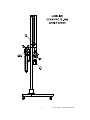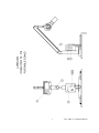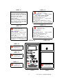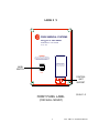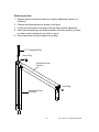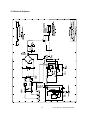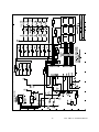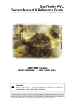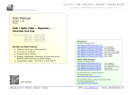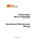
1
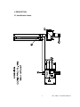
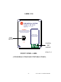
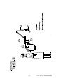
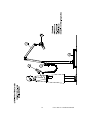
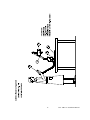
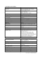
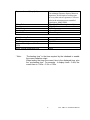
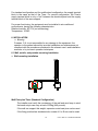
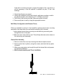
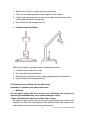
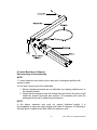
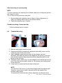
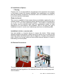
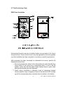
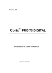
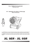
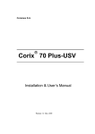
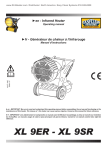
Coramex S.A. Corix PRO 70 Digital VETERINARY X – RAY EQUIPMENT Installation Manual Release 1.0 March 2005. CONTENTS 1. Introduction …………………………………………………. 3 2. Safety Information …………………………………………. 2.1. Warnings …………………………………………………. 3 3 3. Description 5 …………………………………………………. 3.1. Identification Labels …………………………………. 3.2. Equipment Parts …………………………………………. 3.3. Configurations …………………………………………. a. Standard Configuration …………………………. b. Remote Timer Configuration …………………. c. Mobile Stand Configuration …………………. d. Portable Stand Configuration …………………. 5 11 12 12 13 14 15 4. Technical Features …………………………………………. 4.1. Tube Characteristics …………………………………. 4.2. DPM Timer Preset Exposure Times ..……………….. 16 18 19 5. Pre-Installation …………………………………………….. 5.1. Electrical Features …………………………………. 20 21 6. Installation …………………………………………………. 6.1. Wall, Mobile, and Portable Mounting Installation ….. 6.2. Scissors Arm and Extension Arm Mounting ……… 6.3. Arms Mounting on Support …………………………. 6.4. Tubehead Mounting …………………………………. 6.5. Installation of Options …………………………………. 6.6. Electrical Connections …………………………………. 6.7. Final Functioning Tests ……………………………... 22 22 24 25 26 27 27 29 7. Maintenance …………………………………………………. 7.1. General Features ……………………………………... 7.2. Arms Regulation ……………………………………... 31 31 31 8. System Calibration …………………………………………. 33 …………………………………………………. 35 9. Drawings 10. Electrical Schemes …………………………………………. 2 38 Corix PRO 70 Installation Manual 1. INTRODUCTION Corix PRO 70, manufactured by Coramex S.A. performs high quality intraoral radiographs, ensured by the repeatability of examination combined with reduced exposure times and with the small focal spot. Corix PRO 70 has a powerful and user-friendly hand held controller that fits into the palm of your hand. This manual is intended to assist the user and installer in the safe and efficient operation and installation of the equipment described. 2. SAFETY INFORMATION This manual provides all the necessary information for the correct handling of the equipment as well as warnings related to risks associated to Xray generators. Coramex S.A. shall not be responsible for: Any use of the equipment different from what it has been designed for. Any damage to the equipment, the operator or the patient caused by incorrect installation and maintenance not compliant with the procedures contained in the relevant user’s and installation manuals, or by incorrect operation techniques. Any mechanical and/or electrical changes caused during or after installation, different from those reported in the service manual. Any expenses related to the eventual disposal of the equipment or parts. 2.1 Warnings The equipment must be used in compliance with the procedures contained in the present manual and shall never be used for purposes different from those envisaged by it. Only qualified service personnel are allowed to perform technical interventions on the equipment and to remove the tubehead from its support and access the internal components. There is risk of injury if proper procedures are not used. The tubehead cover or the relevant cone-collimator assembly should not be touch during X-ray emission. No objects should be hanged on the extension arms. 3 Corix PRO 70 Installation Manual The equipment is not designed to be used in the presence of flammable anesthetics, oxygen or nitrous oxide. Before performing any maintenance intervention, the equipment must be disconnected from the input line voltage by means of the relevant magneticthermal switch. 4 Corix PRO 70 Installation Manual 3. DESCRIPTION 3.1 Identification labels 5 Corix PRO 70 Installation Manual 6 10 1 8a 8b 3 2 4 6 Corix PRO 70 Installation Manual 7 Corix PRO 70 Installation Manual LABEL # 1 LABEL # 3 WARNING MANUFACTURER: CORAMEX S.A. LAURO VILLAR No. 94-B. 02440 MEXICO, D.F. MEXICO THIS X RAY UNIT MAY BE DANGEROUS TO THE PATIENTAND OPERATOR UNLESS SAFE EXPOSURE FACTORS AND OPERATING INSTRUCTIONS ARE OBSERVED. ELECTRICAL SHOCK HAZARD - DO NOT REMOVE PANELS. RISK OF EXPLOSION - DO NOT USE IN PRESENCE OF FLAMMABLE ANESTHETICS. FOR CONTINUED PROTECTION AGAINST RISK OF FIRE, REPLACE ONLY WITH SAME TYPE AND RATING OF FUSE. MOD: CORIX PRO 70 PART: P103USV X-RAY TUBE HOUSING ASSEMBLY RATED PEAK TUBE POTENTIAL: 70KVp±7% RATED TUBE CURRENT: 8mA±15% TOTAL FILTRATION 2mm. Al SERIAL No.XXXXX FOCAL SPOT: 0.8mm. MANUFATURED: MMMMMMMM/YYYY. MEXICO X-RAY TUBE C.E.I srl ITALY LABEL # 4 LABEL # 2 MANUFACTURER: CORAMEX S.A. LAURO VILLAR No. 94-B. 02440 MEXICO, D.F. MEXICO MANUFACTURER: CORAMEX S.A. LAURO VILLAR No. 94-B. 02440 MEXICO, D.F. MEXICO MOD: CORIX PRO 70 MOD: CORIX PRO 70 X-RAY CONTROL MOD:OX/70-P.S/N.XXXXX COMPLIES WITH DHHS PERFORMANCE STANDARD 21 CFR SUBCHAPTER J. BEAM LIMITING DEVICE PART: P101USV PART: P104USV SOURCE TO SKIN DISTANCE (FFD): 20cm. X-RAY FIELD Ø AT MINIMUM FFD: 6cm. LINE VOLTAGE 120Vac ±10% (109-132Vac) CURRENT MAX. 12A (132Vac) 50/60Hz. CLASS 1 TYPE B SHORT TIME OPERATION SERIAL No.XXXXX MANUFATURED: MMMMMMMM/YYYY. MEXICO SERIAL No.XXXXXX MANUFATURED: MMMMMMMM/YYYY. MEXICO COMPLIES WITH DHHS PERFORMANCE STANDARD 21 CFR SUBCHAPTER J. COMPLIES WITH DHHS PERFORMANCE STANDARD 21 CFR COMPLIES WITH UL 2606-1 SUBCHAPTER J. LABEL # 8a LABEL # 8b LABEL # 5 MANUFACTURER: CORAMEX, S.A. LAURO VILLAR No. 94-B 02440 MEXICO, D.F. MEXICO EXTENSION ARM. PART. P105USV Serial: XXXXX MMMMMMMM/YYYY TO OPEN PUSH THE COVER LABEL # 6 MANUFACTURER: CORAMEX, S.A. LAURO VILLAR No. 94-B. 02440 MEXICO, D.F. MEXICO SCISSORS ARM. PART. P106USV Serial: XXXXX MMMMMMMM/YYYY LABEL # 7 MANUFACTURER: CORAMEX, S.A. MANUFACTURER: CORAMEX, S.A. LAURO VILLAR No. 94-B. LAURO VILLAR No. 94-B. 02440 MEXICO, D.F, MEXICO 02440 MEXICO, D.F. MEXICO MOBILE ARM. PART. P131USV Serial: XXXXX CONTROL UNIT DPM. Mod. P102USV MMMMMMMM/YYYY Serial: xxxxxxxx FRONT 8 MMMMMMMMM/YYYY REAR Corix PRO 70 Installation Manual LABEL # 9 CORIX MEDICAL SYSTEMS Corix Pro 70 - WM - DIGITAL VETERINARY X - RAY SYSTEM 70 KVp - 8mA WARNING THIS X-RAY UNIT MAY BE DANGEROUS TO PATIENT AND OPERATOR UNLESS SAFE EXPOSURE FACTORS AND OPERATING INSTRUCTIONS ARE OBSERVE WHEN NOT IN USE, TURN OFF THE POWER SWITCH AND LEAVE THE CONTROL UNIT HERE MAIN SWITCH POWER CONTROL UNIT SUPPORT FRONT PANEL LABEL SCALE 1:2 (FOR WALL MOUNT) 9 Corix PRO 70 Installation Manual LABEL # 10 CORIX MEDICAL SYSTEMS Corix Pro 70 - MM - DIGITAL VETERINARY X - RAY SYSTEM 70 KVp - 8mA WARNING THIS X-RAY UNIT MAY BE DANGEROUS TO PATIENT AND OPERATOR UNLESS SAFE EXPOSURE FACTORS AND OPERATING INSTRUCTIONS ARE OBSERVED WHEN NOT IN USE, TURN OFF THE POWER SWITCH AND LEAVE THE CONTROL UNIT HERE MAIN SWITCH POWER CONTROL UNIT SUPPORT FRONT PANEL LABEL SCALE 1:2 ( FOR MOBILE STAND AND PORTABLE STAND ) 10 Corix PRO 70 Installation Manual 3.2 Equipment Parts A set of different models of the complete extraoral dental X-Ray device share the certified components listed Model Corix PRO 70 Wall Mount Common Part Particular Part X-Ray Tube Housing Assembly Beam Limiting Device Part: P103USV Part: P104USV X-Ray Control (External Panel), (Control Unit) Part: P101USV Part: P102USV Extension Arm Standard (80cm) Extension Arm Large (90cm) Extension Arm Short (35cm) Part: P105USV Part: P105LUSV Part: P105SUSV Bracket Remote Timer Kit (optional) Scissors Arm Wall Plate Part: P116USV Part: P106USV Part: P115USV Model Corix PRO 70 Mobile Stand Common Part Particular Part X-Ray Tube Housing Assembly Beam Limiting Device Part: P103USV Part: P104USV X-Ray Control (External Panel), (Control Unit) Part: P101USV Part: P102USV Scissors Arm Mobile Base Part: P106USV Part: P121USV Model Corix PRO 70 Portable Stand Common Part Particular Part X-Ray Tube Housing Assembly Beam Limiting Device Part: P103USV Part: P104USV X-Ray Control (External Panel), (Control Unit) Mobile Arm Part: Portable Base Part: P101USV Part: P102USV Part: P131USV Part: P132USV 11 Corix PRO 70 Installation Manual 12 Corix PRO 70 Installation Manual 13 Corix PRO 70 Installation Manual 14 Corix PRO 70 Installation Manual 15 Corix PRO 70 Installation Manual 4. TECHNICAL FEATURES Technical features Equipment Intra-oral Diagnostic X-Ray Imaging (General Purpose Dental) Coramex S.A. Lauro Villar 94-B Mexico, D.F. 02440 - Mexico Corix PRO 70 I type B 120 V ± 10% (109-132 Vac) 50/60 Hz 10 A max (120 Vac) 1.050 KW max @ 132Vac 0.2 Ohms max 120 V < 3% 10 A F Microprocessor Controlled Digital Timer Coramex, S.A. P101USV (panel with Main Terminals Device) DPM Timer (Control Unit) P102USV (Hand Held Controller) Manual time selection, from 0.03 s to 3.00 s, in steps of 0.01 s Plus 9 pre-set exposure times, with automatic line voltage compensation. A pre-heating time of 0.15 s for loading the x-ray tube must be added to the time selection shown on the display. * ± 10% Manufacturer Model Designation Class Rated Line voltage Line frequency Line current Power consumption Apparent line resistance Line Voltage regulation Main Fuse X-Ray Control Manufacturer Part Designation TIMER Part Designation Exposure Times Timer Accuracy Tube Housing Assembly Extra-oral Diagnostic X-ray generator and Beam Limiting Device Coramex S.A. P103USV 70 kVp ± 7% (Single phase, selfrectifying) 8 mA ± 15% @ 120Vac 4.5 mA (over the voltage range) 2 mm Al eq. Oil Bath Thermal Convection Cooling < 50 mR/h (technical Factors 70Kvp, 8mA, 1s) Manufacturer Part Designation Rated output voltage Rated output current Maximum deviation of output current Total filtration Transformer insulation Cooling Radiation leakage at 1 m 16 Corix PRO 70 Installation Manual Exposure Interval (Duty Cycle) 01:30 The minimum Exposure Interval between exposures (30 time units of cooling time for every time unit of exposure) is a Preset value in the microprocessor controlled digital timer, Model DPM. (Part of the Tube Housing Assembly) C.E.I. S.R.L. OX/70-P 0.8 mm (IEC 336) 0.5 mm Al eq. X-Ray Tube Manufacturer Model Designation Focal spot Inherent Filtration Beam Limiting Device Manufacturer Part Designation Minimum Focal Spot to Skin Distance (FFD) X-Ray Field ø at Minimum FFD * Note : Coramex, S.A. P104USV 200 mm 60mm “Pre-heating time” is the time required by the tubehead to enable the correct radiation output. When testing the timer the correct time is the displayed time, plus the “pre-heating time”. For example : it display reads : 0.40s, the correct time is : 0.40s + 0.15s = 0.55s. 17 Corix PRO 70 Installation Manual 4.1 Tube Characteristics 18 Corix PRO 70 Installation Manual 4.2 DPM Timer- Preset Exposure Times The following table of pre-set exposure times in Seconds shows the rated exposure time for a nominal line voltage of 120V and the final corrected exposure time, as a function of the line voltage correction factor and patient size, for the minimum (109V) and maximum (132V) line voltage operating range. 19 Corix PRO 70 Installation Manual Notes: • Suggested exposure times in Seconds, for E type films. • Film speed: Factory pre-set for E type Films. If set for Digital x-ray, (C.C.D. Sensor), pre-set exposure times are reduced by 1/3. • Corrected exposure times rounded to the nearest 1/100 of second. • This table will not show the added 0.15 seconds of preheating time for the x-ray tube. LINE VOLTAGE LINE VOLTAGE CORRECTION FACTOR PATIENTS SIZE 120V 1.0 109V 1.9 132V 0.55 MEDIUM SMALL MEDIUM SMALL MEDIUM SMALL 0.24 0.24 0.30 0.33 0.16 0.16 0.20 0.22 0.47 0.47 0.57 0.63 0.31 0.31 0.38 0.42 0.13 0.13 0.16 0.18 0.09 0.09 0.11 0.12 INCISOR CUSPID BICUSPID MOLAR 0.18 0.18 0.21 0.24 0.12 0.12 0.14 0.16 0.33 0.33 0.41 0.47 0.22 0.22 0.21 0.31 0.09 0.09 0.12 0.13 0.06 0.06 0.08 0.09 PAW 0.24 0.16 0.47 0.31 0.13 0.09 UPPER JAW INCISOR CUSPID BICUSPID MOLAR LOWER JAW 5. PRE - INSTALLATION Proper planning prior to installation is required. There are three areas of concern before installation. 1) Mounting structure 2) Reach of the tubehead 3) Electrical connections ⇒ Warning The precision of the installation is the full responsibility of the installer. Inappropriate installation of the equipment may cause it to drop from its support, resulting in damage to individuals and materials near its range. The manufacturer fully disclaims expressed or implied in this regards. Different wall structures require different type of fasteners. It is the responsibility of the installer to use the appropriate fasteners. Always making sure that the installation is properly leveled. 20 Corix PRO 70 Installation Manual The timer, supply plate, hand remote control and connection cable assembly supplied by the manufacturer must be kept unadulterated. Using different parts requires new system calibration. Judgment of wall sturdiness is left to the installer. Fixing bosses to be used for each type of wall are the following: ⇒ Concrete walls: expansion bosses ⇒ Wooden studs: self-threading screws ⇒ Hollow bricks: chemical bosses 5.1 Electrical Features The supply line must meet the following requirements: Single-phase mains voltage + ground: 120V±10% Line frequency: 60Hz Absorbed current: 10A (120V) Apparent line resistance: 0,2Ω max (120V) The equipment must be wired to an electrical panel whose characteristics comply with the electrical norms in force in the country where it is installed. A dedicated line protected by a 10A circuit breaker is recommended. The general ground connection must be performed according to the norms in force. Inadequate ground connection of the equipment may represent a hazard for the operator and/or cause the electrical equipment to malfunction. Maximum distance between electrical panel and supply terminal block varies according to the section of supply wires and is reported in following table. 120 V 60 Hz Minimum Required Wire Size 12 AWG 4mm2 10 AWG 6.3mm2 Wire Run Distance 25 Feet 7.5 Meters ************* 50 Feet 15 Meters ************* *********** 75 Feet 22.5 Meters For 120 V supply, is recommended to use wires whose section is not lower than 4 mm2 (12 AWG). 21 Corix PRO 70 Installation Manual For standard configuration and for mobile stand configuration, the supply terminal block is the same as that of the Timer. For remote configuration, the Timer’s supply terminal block is only a “link” between the electrical panel and the supply terminal block of the arms support. For proper functioning, the equipment must be installed in air-conditioned environments, having the following characteristics: Relative humidity: 50-75% (not condensing) Temperature: 18-28C 6. INSTALLATION ⇒ Warning Coramex, S.A. is not responsible for any damage to the equipment, the operator or the patient caused by incorrect installation and maintenance not compliant with the procedures contained in the relevant user’s and installation manuals, or by incorrect operation techniques. 6.1 Wall, mobile, and portable mounting Installation Wall mounting installation Wall Plate plus Timer (Standard Configuration) The installer must verify the consistency of the wall and must keep in mind that each set pin can carry a load of 200kg (440 pounds). If the wall can support this weight, expansion metal cast pins can be used. If the fixing position has wooden studs, screws of 8 x 40 mm can be used. 22 Corix PRO 70 Installation Manual If the wall is not strong enough to support the weight of the x-ray device, it will be necessary to use the optional 4 synthetic set pins, 12 mm, with bushings. 1. Check that all parts are present. 2. Check wall consistency and mark holes for wall plate mounting on wall in the selected position, at a distance of 57” (1450mm) from floor. 3. Drill holes in wall and mount plate. Make sure plate is leveled. 4. Secure wall plate to wall by using the appropriate screws. Wall Plate (Configuration with Remote Timer) Follow as indicated in section 6.1 but install the optional remote timer mounting assembly in the area where the hand switch assembly will be located. 1. Insert optional remote timer mounting on wall and bring connecting wire through the hole on the plate. 2. Make sure wire strain relief is used. This will help eliminate undue stress on the connecting cord assembly. Control Box Assembly 1. Remove control box cover by loosening the relevant captive screws. 2. Secure control box to plate by using the screws, and check that top plane is leveled. 3. Make sure power wires are brought through the internal hole and prepare for electrical installation. Mobile stand mounting and Timer Installation 23 Corix PRO 70 Installation Manual 1. Make sure all parts for mobile mounting are present. 2. Cross the two base legs and fix them together to the column. 3. Position the articulated arm (do not remove safety belt) into the column, making appropriate wire connections. 4. Mount tubehead following section 6.4 Portable stand Installation Make sure all parts for portable stand mounting are present. 1. Position base on table to be used. 2. Fix removable legs into the base. 3. Position the arm into the column, making appropriate wire connections. 4. Mount tubehead following section 6.4 6.2 Scissors Arm and Extension Arm Mounting Assembly of extension arm and scissors arm ⇒ Warning Do not remove safety belt from scissors arm. Releasing the arm prior to mounting the tubehead may cause severe damage or injury. Check that Extension Arm pivot is fitted with a spacer. By means of tape, put the scissors arm cable and extension arm traction wire together. Pull wire until cable appears, then separate cable from traction wire, and introduce scissors arm pivot into extension arm. 24 Corix PRO 70 Installation Manual 6.3 Arms Mounting on Support Wall mounting of arms assembly NOTE -To insert extension arm rotation pivot, keep arm in orthogonal position with respect to plate. -Do not free scissors arms from safety belt. 1. Mount complete extension arm on wall plate, by inserting rotation pivot in the relevant thimble. 2. Check that the extension arm this leveled through a level; the plate of wall should be leveled horizontal and vertical, if is necessary can wear the plate against the wall to obtain the level desired. NOTE In this phase, extension arm must not support tubehead weight; it is recommended to keep the angle slightly wider than 90 degrees, this allowing a full-load flexion of about 4 mm with a 900 mm extension arm. 25 Corix PRO 70 Installation Manual Stand mounting of arms assembly NOTE -To insert extension arm rotation pivot in thimble, keep arm in orthogonal position with respect to stand. -Do not free scissors arms from safety belt. 1. Mount scissors arm (extension arm is absent in this configuration) on stand, by inserting rotation pivot in the relevant thimble. 2. Check that extension arm is leveled. Portable mounting of arms assembly 1. Mount articulated arm on column. 6.4. Tubehead Mounting 1. Remove safety screw located on joint. 2. Keep arm articulation at maximum height and slide safety cover over the connection post of the scissors arm. 3. Insert tubehead connection pivot post into the scissors arm-post assembly, about half way. Slide in the wedge into the groove on the pivot post and then push the head upwards until the wedge sits itself into the groove of the pivot post. 4. Completely insert rotation pivot, so that wedge fits the relevant slots on the pivot. Only after this has been carried out, the scissors arms holding pack can be removed. 5. Lower cover on wedge and screw safety screw back. NOTE -The function of the cover is to avoid that wedge leaves the relevant seat. Therefore, cover must be held in the right position by means of the relevant holding screw. -All operations for extension arm friction regulation must be performed. 26 Corix PRO 70 Installation Manual 6.5 Installation of Options ⇒ Warning Coramex, S.A. is not responsible for any damage to the equipment, the operator or the patient caused by incorrect installation and maintenance not compliant with the procedures contained in the relevant user’s and installation manuals, or by incorrect operation techniques. Single stud mount This mount is available for those cases where an installation requires the use of a limited surface. The term single stud means that the stud must be at least two 2 x 4 or two 2 x 6 inch studs sandwiched together. The installer is reminded that this feature must be carefully used since the manufacturer makes no claim whatsoever as to the fitness of this installation. Most of the times this type of installation is used to mount onto a cabinet type structure or subdividing walls. Installation to brick or concrete walls Use lead shields or chemical bosses to secure the device. Follow proper shielding utilization procedures. Always secure the device so as to make a solid fastening. Sandy and hollow bricks may be dangerous. Consider using all thread rods or bolts to go through walls and use another external fastener or clamp to hold baking in a secure place. 6.6 Electrical Connections The device must be connected to a properly grounded power source. Follow all applicable electrical regulations. Use dedicated lines with the correct gauge and circuit breakers. 27 Corix PRO 70 Installation Manual Electrical connections for standard versions Refer to section 5.1 for appropriate wire size. 1. Connect power cables from the wall source to the terminal block of the control box by means of a bipolar cable + ground, whose minimum section must be 14 AWG, crimp the terminals provided to the ends of each wire and insert them into the appropriate terminal on the connection block. Labels indicate the following: L=Line (black wire), N=Neutral (white wire) Ground symbol – ground wire (green cable) 2. Connect tubehead cable from arms to the main P.C. Board as follows: Crimp the terminals with the appropriate connectors and connect them as indicated to the sliding connectors shown on the P.C. board. The black wire to L (live tubehead wire), the white wire to N (neutral tubehead wire) and the ground wire (green) to a physical ground. Electrical connection for versions equipped with remote Timer For this case the control unit (timer DPM) can be located in a remote place as indicates the section 3.3(b), use the bracket remote timer to hold the control to the wall and connect the timer remote with the PC board through a flat cable type telephonic of 4 threads with a not greater length to 10mts. (30 feet), with connectors RJ hand set in its extremes (assure to do the cable according to the electric diagram) 28 Corix PRO 70 Installation Manual 6.7 Final Functioning Tests DPM Timer Description All equipment functions are set at standard values and are tested in the factory during final tests. Some of the functions may be regulated by Service engineers only after installation has been completed or according to specific requirements. After equipment has been connected to a dedicated line source, perform the following functional tests: 1. Set circuit breaker line switch to the ON position and verify that the front rocker switch on the control box is illuminated when it is set in the ON position. Verify also that the Hand Control display shows a given value and that the relevant keys are illuminated. 2. Check correct functioning in automatic mode by depressing relevant function-selection keys in sequence. Each of the relevant LED’s will light up with its corresponding timer numerical value visualized on the display. 29 Corix PRO 70 Installation Manual 3. Select manual function by pressing the relevant keys and check that display visualizes the different manual exposure times. The following test implies emission conditions. Follow all applicable regulations and safety precautions. 4. Position fluorescent screen for radiation visualization at extreme end of collimator, press relevant X-ray Switch key and check simultaneous switching on of LED ((X-ray signaling) and generation of acoustic signal accompanying x-ray emission. Keeping X-ray Switch pressed, the display will visualize the real exposure time. Error Messages ⇒ Error message LO on display means that mains input voltage is too low and not within the accepted limit of -10%. ⇒ Error message HI on display means that network input voltage is too high and exceeds the accepted limit of +10%. ⇒ IN case calculated exposure time is higher than 4s, no exposure will be performed. If these error messages are frequently displayed, adjust input mains voltage as indicated in Section 8. Once these checks have been completed, Equipment is ready for use. 30 Corix PRO 70 Installation Manual 7. MAINTENANCE 7.1 General Features Corix PRO 70 requires correct use and also regular maintenance and checks. Such measures will guarantee safe and effective equipment functioning and will prevent any risk for both patient and operator. Maintenance checks that can be performed by the operator and periodical maintenance interventions to be performed by Service engineers only are the following: Regularity Test Type Annual Check that tags are intact and correctly secured Check that no oil traces are present on tubehead Check that hand remote control cable does not reveal signs of interruption or abrasion Check that equipment does not revel external signs of damage which could affect safety protection from x-ray Check scissors arm balancing Every two years Check x-ray beam centering Check tube current absorption 7.2 Arms Regulation Arms regulations do not require removal of tubehead. In case this operation is considered useful or necessary, before removing tubehead bring scissors arm in closed position and secure it with safety fixing device. This operation is necessary to avoid damage to people and to the arm. Arms regulation may be necessary in the following cases: Scissors arm is not perfectly balanced; in this case, operate on spring regulation. After a certain time, arms balancing springs may sag. Should this happen, tubehead will no longer be balanced in all positions and spring calibration will be required. Extension arm friction regulation 1. Locate and remove the plastic cover at the end of the arm. 2. Access the friction screw behind this cover. 3. Regulate friction by means of a hexagonal wrench and check arm rotation. 4. Once friction adjustment is achieved replace cover. 31 Corix PRO 70 Installation Manual Balancing of arms 1. Observe arms to determine which one requires adjustment (Anterior or Posterior). 2. Position the articulated arm as shown in the figure. 3. Locate and remove the cover plug of the arm that requires adjustment. 4. Insert the hexagonal key and rotate clockwise if the arm tends to go down or rotate counter clockwise if arm tends to go up. 5. Once adjustment is finished replace cover plug 1/2" Hexagonal Key Cover Plug Articulated Arm Anterior Cover Plug Articulated Arm Posterior 32 Corix PRO 70 Installation Manual Tubehead replacement -The scissors arm must be held closed together using a heavy-duty strip. This will avoid serious injury to personnel or assembler and limit the potential arm breakage. 1. Remove screw from scissors tubehead arm holder 2. Hold Arm at top height, hold the defective tubehead and slide sleeve upwards and hold it with a piece of tape. 3. Remove the wedge securing the tubehead assembly and gently work the tubehead pivot post out. Care should be exercised not to damage the arm or the connection. 4. Proceed to install the replacement tubehead as instructed under section 6.4 8. SYSTEM CALIBRATION Corix PRO 70 with DPM timer is calibrated at the factory prior to shipment for the nominal voltage of 120 VAC. However, any of the following situations requires a new calibration: 1. Hand Control replacement 2. Cord replacement 3. Installation of remote control systems 4. Main P.C. Board replacement 5. When display indicates either LO (low voltage) or HI (high voltage) Calibration and adjustment of the DPM timer The DPM timer requires calibration and adjustment according to manufacturer’s specifications for the nominal voltage of 120 volts. This is necessary to enable the timer adjustment, by the software algorithm, to be made within a specified window or voltage range. Any voltage exceeding this range will cause an error code such as LO or HI. The timer is calibrated to the power supply at the factory any deviation will result in a new calibration requirement. Calibration affects the relationship between power supply, the length of the interconnecting cable between the hand control and the control box and the hardware associated with the timer and the main P.C. Board. Qualified technicians must perform calibration. a) Test equipment: Digital voltmeter (true RMS preferable) b) Procedure: 33 Corix PRO 70 Installation Manual Connect the leads of the voltmeter to the input terminals and verify the correct voltage (120 ± 10%). Power up the device while simultaneously pressing the “Up” and “Down” keys to enter the calibration mode. The display will now show “CAL” and after 3 seconds the voltage reading. Compare this value to the voltage reading of the voltmeter. Calibrate the displayed voltage value to the voltmeter use by selectively pressing the “UP: and “DOWN” keys. Once the values correspond press the X-Ray key to accept this new value. At this point the displayed voltage value might begin to flicker or change according to the true voltage cycling followed by 0.00. Unit is now calibrated, to exit this mode simply press any of the patient selection keys Timer Multiplication Factor Occasionally the end user may need to use timer settings other than those preset at the factory. For example when different types of film speeds are required. The unit is capable of automatically varying these values to reflect the new time setting required. The multiplication factor can be changed from a value of 1.31 to 0.69. At the factory is set for a value of 0.69. Values less than 1.00 will reduce the timer setting while those above will increase the time settings for the automatic keys. a) Procedure: Power up the device while simultaneously pressing the “Up” and “Down” keys to enter the calibration mode. The display will now show “CAL” and after 3 seconds the voltage reading. Press the “Tooth selection” key, the display will now show “FAC”. To increase time press the “UP” key until the display indicates 1.31, to decrease time press the “DOWN” key until the display indicates 0.69. To exit this mode press the “Patient selection” key, the factor will be save in the timer memory. To cancel the factor start the procedure without pressing the “UP” and “DOWN” keys and the factor will be 1.00 once again. 34 Corix PRO 70 Installation Manual 9. DRAWINGS EXTENCION ARM=”A” TOTAL REACH=”B” TOTAL INSIDE REACH=”C” DISTANCE=”D” 13 3/4” (35 cm) 25 3/4” (65.4 cm) 53 3/8” (135.6 cm) 27 3/8” (69.4 cm) ST 31 1/2” (80 cm) 43 1/2” (110.5 cm) 71 1/8” (180.6 cm) 45” (114.4 cm) 35 3/8” (90 cm) 47 1/2” (120.6 cm) 75” (190.6 cm) 49” (124.4 cm) 35 Corix PRO 70 Installation Manual 36 Corix PRO 70 Installation Manual 37 Corix PRO 70 Installation Manual 10. Electrical Schemes 38 Corix PRO 70 Installation Manual 39 Corix PRO 70 Installation Manual Coramex S. A. A Division of Corix Medical Systems 94-B Lauro Villar Mexico City, D.F. 02440 – Mexico Phone: 011-52-555-394 -1192 Fax: 011-52-555-394 -8120 Cat. Part # P141PRO R1.0 40 Corix PRO 70 Installation Manual