1
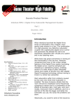
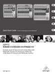
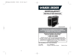
Installation Manual for
iPaul Amplifier
iPaul 2.400
2-Channel Amplifier
Part-No. 271050
RAC GmbH & Co. KG - P.O. Box 12 25 - 74899 Bad Rappenau - Germany
Telephone +49-7066 / 9006 0 - Telefax +49-7066 / 9006 50
User Safety Notice
Please read all warnings in this manual. They inform you of possible risk of personal injury and damage to
property!
These products are intended for use only by those possessing the necessary specialized training. The
relevant safety regulations regarding auto parts, regulations on internal vehicle safety STVZO-TÜV, as well
as regulations of the authorized vehicle manufacturers should be diligently followed.
Hearing Impairment
Sustained volumes in excess of 85 dB can, over time, impair hearing ability. Rainbow® amplifiers are capable of
producing volume levels of over 85 dB.
Volume and Driver Awareness
Use of musical devices can obstruct important traffic noises, thus posing an increased risk of accident while
driving.
Rainbow® does not take responsibility for hearing impairment, injury, or damage to property arising from the use
or mis-use of its products.
Work to Vehicle
Do not begin operation of vehicle before all components of the loudspeaker system and the amplifier are firmly and
securely in place. Many parts, when unsecured, can become airborne and hazardous during sudden braking or in
the event of an accident.
Do not bore or screw into vehicle lining or carpet before making certain that no important parts or cables lie
beneath. Pay close attention to avoiding gasoline, brake, and oil lines and electrical cables when planning the
assembly.
Before beginning assembly, disconnect the negative terminal (-) of the car battery to avoid possible short-circuits.
Should any part of the autobody require cutting or removal during assembly of the loudspeakers and amplifier,
contact an autobody shop.
Damage to basic auto body parts can void the vehicle operating permit!
Use caution when removing inside panellings. Vehicle manufacturers use a diverse range of fastenings that can be
damaged with disassembly.
!Danger of Electrical Shock!
Do NOT disturb the amplifier or loudspeaker connection during operation!
2
Table of Contents
User Safety Notice
Technical Data
Technical Specifications
Front View and Controls
„Controls“
Installation
Remote Connection
Switching On / Control Function with LED
Amplifier „LOW INPUT“
Output „LINE OUT“ for Subsequent Amplifiers
Remote Control
Bass Boost
„Cable Diagram: Amplifier, Radio, Loudspeaker“
Broadband Mode
Broadband Mode Frequency Response
High-pass Mode
High-pass Mode FRONT Frequency Response
Low-pass Mode
Band-pass / Low-pass Mode Frequency Response
Bandpass Mode
Loudspeaker Connection Stereo
Loudspeaker Connection Mono-Bridged
Loudspeaker Connection Tri-Mode
Power Provision Indications
Determining „Central Ground“
„Principal Connection Diagram: Central Ground“
Warranty Terms and Conditions
iPaul 2.400
4
6
6
7
7
8
9
9
10
10
10
10
11
12
12
13
13
14
15
15
16
16
17
17
18
18
19
19
21
22
Figure 1
Figure 2
Figure 3
Figure 4
Figure 5
Figure 6
Figure 7
Figure 8
Figure 9
This package contains:
-
iPaul 2.400 amplifier
Mounting screws
Dear Valued Customer,
We congratulate you on your purchase of this superior product and thank you for placing your trust in Rainbow.
We have developed this installation manual with consideration to variations in automobile mechanical and
acoustical characteristics. Nevertheless, mistakes can occur. We would greatly appreciate your bringing any
problems you encounter within to our attention.
Sincerely,
Your Rainbow Team
3
Before Beginning
iPaul 2.400
Notice
The installation and adjustment of the amplifiers should be made only by qualified persons.
Read the operating instructions carefully and follow all directions regarding connection and adjustment of the
amplifier.
Warning
Consider all appropriate references in the operating instructions before attaching external devices that do not
belong to the amplifier.
Do not open or attempt to repair the amplifier yourself. When technical service is necessary, rely exclusively on
your dealer. Any unauthorized changes to the amplifier will void the warranty.
Installation
Warning
The amplifiers are designed exclusively for the vehicle interior and 12 Volt DC electrical current. The ambient
temperature may range from 0° to 60°C.
Install the amplifier only in the car interior or trunk. Do not install the amplifier in the engine compartment.
The amplifier should not be placed under pressure or covered.
Make certain that no foreign particles or moisture can get into the amplifier. Ensure there is sufficient ventilation
for the proper cooling of the housing.
Attachment
Warning
The optimal placement of the amplifier is in a vertical position in an area of the vehicle permitting good air
circulation.
The heatsink can reach temperatures of over 80°C; Avoid contact with heat-sensitive surfaces and materials.
Ensure that no elements that can be damaged by screws or the attachment process are located in the designated
installation area.
Damage to the vechicle can compromise automobile safety and endanger passengers.
Fasten the amplifier to the four mounting straps. Ensure the surface is firm and stable and can withstand the
necessary load. Avoid attachment to plastic parts or paper-based materials.
4
Connecting Cables
iPaul 2.400
Warning
Use only electrical cable with a sufficient diameter. For our technical purposes a larger diameter is always
recommended.
The diameter of the grounding cable must be at least as large as that of the positive cable.
Lay the cables one by one and in succession. Pay attention to performing a professional installation. Always use
rubber sleeves for protection when wiring through metal. Use appropriate lugs and insulation caps.
Do not bend the cables at a right angle. Avoid contact with sharp metal or surfaces that could damage the
insulation.
Connecting Cables
Warning
Separate the clamps of the current supply from the battery before maintenance, assembly, or disassembly. In all
cases at least the negative pole should be detached.
Always install a fuse at the positive current supply cable of the battery and as near as possible to the battery clamp.
When possible use the included fuse.
Always follow the accompanying instructions when connecting an external condenser.
We do not accept responsibility for damage caused by the inappropriate use of an external power supply.
Connecting and Installing
Warning
Make sure that the grounding connection is sound. Attach the cable to a metal part of the vehicle from which the
lacquer or other surface finish has been removed.
Use cables of the appropriate length, keeping them as short as possible.
In order for the anti-interference system to function, the RCA sockets may not come into contact with the metal
enclosure.
Packaging
The amplifier is packaged in a cardboard box designed for its protection. Do not damage the packing and keep it
for later use in case of damage.
Upon receipt of the amplifier make sure that:
1.) The packaging is intact, the contents correspond to the specifications, and the product is in no way damaged.
2.) In the event of missing or damaged parts, please contact your dealer immediately. Refer to both the model and
serial number, which can be found on the underneath of the amplifier.
5
Technical Data
•
•
•
•
•
•
•
•
•
•
•
•
•
iPaul 2.400
Performance amplifier with integrated high-current MOSFET-switch power supply.
Inverted Output stages for performance coupling during mono-bridged mode.
Output stage 2 Ω stable, bridge and tri-mode capable.
Amplifier design for minimal noise.
Reversible safety switch-off with thermal monitoring.
Safety switch-off with DC current to loudspeakers.
Safety switch-off for loudspeaker short-circuit and loudspeaker under impedance.
Integrated flat fuse 2 x 25 A in accordance with DIN-standard, replaceable from outside.
Softstart remote muting for suppression of switch-on peaks.
Low power requirements for remote-muting electrical circuits.
Palladium-plated 25 mm² power and 10 mm² loudspeaker connection.
High-tech semi-SMD built structure with low coupling wiring
Interference-proof certified by European E-Norm.
Technical Data
Output Power Stereo 4 Ω
Output Power Stereo 2 Ω
Output Power Mono 4 Ω
Total Harmonic Distortions THD+N
Signal-to-Noise Ratio S/N
Frequency Response -3 dB
Input Sensitivity Level In
Input Impedance Level In
Connection Impedance Stereo
Connection Impedance Mono
Connection Impedance Tri-Mode (Woofer + Satellite)
Damping Factor
Operating Voltage
Input Power Max. @ 14.4 V
Input Power Remote
Idle Input Power without Signal
Temperature Monitoring heatsink
Short-Circuit Protection – Overload
Softstart-Muting On / Off
Dimensions: W x H x D
Weight
e-Approval No.
2 x 130 Watt rms
2 x 200 Watt rms
1 x 400 Watt rms
<0.04 %
>95 dBA weighted
10 Hz – 35 kHz
250 mV – 6 V
10 kΩ
2 x 4 Ω / 2 x 2 Ω possible
1 x 8 Ω / 1 x 4 Ω possible
1 x 4 Ω + 2 x 4 Ω Tri-Mode
> 200 at 4 Ω
11 V - 16 V DC
48 A at 1% THD
8 mA
< 0.4 A
70°C Power Down
Immediate Power Down
1s Delay
355 x 60 x 250 mm
4,5 Kg
E11 10R-024085
Active Controls:
High-pass / Subsonic
Low-pass
Band-pass
Phase Shifter
Remote Control (5m Cable)
15 Hz – 500 Hz, 12 dB/Oct.
50 Hz – 5 kHz, 12 dB/Oct.
15 Hz – 5 kHz, 12 dB/Oct.
0° - 180° Infinitely Variable
Level and Phase Infinitely Variable
6
Front View and Controls
iPaul 2.400
Figure 1: Controls
7
1 = Power connection (–) minus, body and/or central ground.
2 = Remote connection of CD-radio.
3 = Power connection (+) plus, only over fuse.
4 = Flat fuse 2 x 25A in accordance with DIN-standard, replaceable from outside Replace only with like kind!
5 = Connection for external thermostat module (optional) and fan module (optional).
6 = Loudspeaker connection.
7 = Input socket „LOW INPUT“ for signal input of CD-radio.
8 = Signal output „LINE OUT“ for subsequent amplifiers
9 = Remote output for remote control
10 = Switch for high-pass or band- / low-pass operation
11 = Bass Boost
12 = Connection for peak performance coupling module (optional)
13 = Function control: blue logo = amplifier in operation, flashing logo = protection mode.
14 = „GAIN“ control for adjustment of input sensitivity for „LOW INPUT“
15 = Control for phase shifter
16 = Control for cut-off frequency low-pass
17 = Control for cut-off frequency high-pass
Installation
Fasten amplifier to a suitable, well-ventilated location in the vehicle, if possible to the auto body, with included
sheet metal screws and insulated washers.
The amplifier’s heatsink can get very hot, making sufficient distance to temperature sensitive parts absolutely
necessary.
Caution:
Clamp the negative pole of the battery before working on connections. This work requires expertise
and should be performed with careful consideration to the relevant safety regulations.
Before connecting the power supply and loudspeaker cables all screws on the amplifier terminal block must be
unscrewed in an upward direction, so that the screws do not obstruct the path of the cables. Under no circumstances
should screws be completely unscrewed, however.
Caution:
Important Safety Notice Concerning Risk of Fire and Injury.
Unscrewing or turning of the screws on the amplifier terminal block during active amplifier operation
(amplifier is performing) is not permitted, as the risk of a short circuit between the screwdriver and the
heatsink cannot be excluded, thus making extreme damage to the amplifier or car, or a burn injury
caused by the electrical current on the screwdriver, unavoidable.
Drilling out the amplifier terminal block for the purpose of cross-section extension for cable insertion
can cause damage to the electronics and will result in an immediate voiding of the warranty.
8
Attach red cable with diameter of 4 mm2 to 10 mm2 directly to the positive terminal (+) of the battery or the
central positive point of the HiFi unit and run to the amplifier. Make absolutely certain that the main electrical
cable is secured with a fuse. (see below).
Provide the free end of the power cable with a protective sleeve and insert into the clamp “B+“ (3) of the amplifier.
Firmly tighten the clamping screw.
Connect black cable with diameter of 4 mm2 to 10 mm2 directly to the autobody or to the central ground of the
HiFi unit and run to the amplifier.
Provide the free end of this power cable with a protective sleeve and insert into the clamp „GND“ (1) of the
amplifier. Firmly tighten the clamping screw.
The total electrical consumption of the complete audio system must be calculated to determine the appropriate fuse
to be employed. Therefore, the total electrical requirements of each audio device must be considered. Review
manufacturers data for each individual unit and add together to determine total consumption (include fuses with
Amp data). The resulting sum is the total electrical consumption in ampere and corresponds to the fuse
requirements. The fuse must always be inserted into the main power cable directly behind the battery (+).
Remote Connection
Run cables with small diameter from the car radio or CD-player-remote terminal to the amplifier connection
„REM“ (2) using a protective cable sleeve.
When switching the car radio/CD player on and/or off the amplifier is switched on and/or off over a soft muting
with a time delay of approximately one second.
Switching On / Control Function with LED
The powering on of the amplifier is indicated by the blue light at the unit’s logo (13). The amplifier switches on
with a time delay of approximately one second. Uncontrolled motion of the loudspeakers is suppressed by this soft
start when switching on the amplifier.
In the event of severe under impedance (<2Ω), for example, complex load, short-circuit at the loudspeaker outputs,
direct current at the loudspeaker voice coils, or with overload causing too-high temperatures on the heatsink, the
electronic monitor immediately powers the amplifier off. → blue flashing logo (13) (= protection).
After the repair of the disturbance the amplifier can be reactivated by repeated on/off switching.
If the powering down of the amplifier was caused by overload and too-high temperature, it will restart itself
automatically after a cooling phase.
Frequent powering off for thermal reasons indicates a poor designation of location, and the amplifier should be
relocated to a well-ventilated area. A persistent indication of trouble suggests that a defect in the equipment is
present. The amplifier should be sent in for repair.
9
„LOW INPUT“ Connection: Amplifier Input
iPaul 2.400
The output signal of the car radio/CD player is fed by means of a RCA socket "LOW INPUT" (7) R (right) and L
(left).
During mono operation of the output stage the „LOW INPUT“ (7) must always be fed with a right and a left signal.
The full mono performance is achieved only with simultaneous signal input on the right and left RCA sockets.
When only one mono signal is available, for example, during operation over an active crossover with only one suboutput, the sockets (7) must be fed with a Y- adaptor.
Caution:
Use of different RCA cable lengths could potentially lead to potential differences. A variation in
lengths can cause a ground loop, resulting in unpleasant generator distortion. Do not lay RCA cables
parallel with power cables, in order to prevent distortion couplings.
„LINE OUT“: Subsequent Amplifier Output
The unmodified input signal from „LOW INPUT“ (6) R & L is free at outputs „LINE OUT“ (8) R (right) and L
(left) and can be used for subsequent amplifiers.
„REMOTE“: Remote Control
Connect the included 5m black cable with one end of the included remote control and insert the other end of the
cable into the designated socket „REMOTE“ (9) on the amplifier. Phase and volume can now be controlled
remotely with the potentiometers „GAIN“ and „PHASE”.
Caution:
The volume “GAIN” on the remote control can be set between the minimum and the set volume on
potentiometer “GAIN” (14) of the amplifier only. It is recommended to set a reasonable basic volume
by potentiometer “GAIN” (14) first and use the remote control for fine tuning afterwards. The settings
remain in effect only as long as the remote control is plugged in. If the remote control is unplugged,
the settings on the potentiometers „GAIN“ (14) and „PHASE“ (15) of the amplifier take effect. If the
remote control is again plugged in, the settings of the remote control once more take effect.
Bass Boost
For vehicles with high sound absorption, bass rendition can be raised from 45 Hz up to +12 dB with the switch
„BASS BOOST“ (11). Adjust the bass rise depending on loudspeaker location and listening tastes. The correct
setting is achieved when the bass rendition has a full, dry sound. Too strong of a bass rise can, with high volumes,
lead to an overload of the subwoofers! A level of +12 dB is equal to 16-times (!) volume load and gives the bass
rendition an unnatural sound.
• Set „BASS BOOST“ (11) switch to „6dB“ or “12dB”
10
Figure 2: Cable Diagram Amplifier, Radio, Loudspeaker.
11
Operation Mode: Broadband
iPaul 2.400
In this mode of operation all linear frequencies from 10 Hz to 35 kHz are processed and amplified without
preference. Frequency separation takes place exclusively in the passive crossovers of the respective loudspeaker
systems. This mode of operation is therefore suitable for all kinds of loudspeakers and loudspeaker systems in
which frequency separation occurs via passive crossovers.
•
Set „X-OVER“ (10) switch to „FULL“.
Figure 3: Frequency Response for Broadband Mode, “FULL” setting
12
Operation Mode: High-pass
iPaul 2.400
This mode is used principally for kickbass operation of a front system or as subsonic filter for the bass load throwoff of a front system. The maximum load of the kickbass loudspeakers can be substantially increased in this mode.
The high-pass, with 60-70 Hz and 12 dB slope per octave, removes frequencies below 60-70 Hz, which are
superfluous and harmful to the kickbass loudspeaker, thereby significantly improving the performance and lifespan
of the speaker. The kickbass performance of the loudspeaker is in no way reduced, but rather, the capabilities are
improved. Additionally the loudspeaker thermal and mechanical capabilities are strengthened.
• Switch „X-OVER“ (10) should be adjusted to setting „HPF“ and the cut-off frequency should be set by means
of the potentiometer „HPF“ (17) to between 15 Hz – 500 Hz.
In this setting, as described above, all frequencies below 60-70 Hz are removed with large slope from the
loudspeaker and therefore cannot be reproduced. Only the frequencies from 60-70 Hz to 35 kHz are fully available.
Therefore, in this mode a separate amplified subwoofer, which reproduces all frequencies below 60-70 Hz is
absolutely necessary.
Figure 4: Frequency Response of High-pass Operation Mode
13
Operation Mode: Low-pass
iPaul 2.400
This mode of operation is used exclusively when the amplifier is assigned to subwoofer mode. The internal active
crossover allows only frequencies under the set cut-off frequency of 12 dB slope per octave to pass. A low
decoupling frequency of <100 Hz has the advantage that a subwoofer, which is usually installed in the trunk, no
longer stands out, but rather blends into the complete sound picture.
• Set switch „X-OVER“ (10) to „BP/LPF“ and, using the potentiometer, adjust the cut-off frequency „LPF“ (16)
to between 50 Hz – 5000 Hz. Set the potentiometer “HPF” (17) all the way left to 15 Hz.
Adjust level of subwoofer with controller „GAIN“ (14).
The phase position of the subwoofers should be checked against the basis system after start-up of the complete
system. The phase position is correct when the deep bass rendition is short and dry. Spongy and weak deep bass
rendition indicates phase errors. The phase position of the subwoofers can be changed by adjusting the
potentiometer „PHASE“ (15). Adjust settings on the „PHASE“-controller (15) until the bass rendition is optimal.
Caution:
The phase shifter functions only when the „X-OVER“ switch (10) is in the „BP/LPF“ position.
TIP:
Insert the included remote control for „GAIN“ and „PHASE“ in the „REMOTE“ (5) socket and,
from the driver’s seat, adjust „GAIN“ and „PHASE“ until the bass rendition is optimal.
TIP:
Accompany pure subwoofer operation with high-pass with a cut-off frequency of 20-30 Hz. This
increases the power handling and lifespan of the amplifiers and subwoofers!
Many subwoofers cannot correctly render frequencies below 30 Hz, producing instead hot air
without volume. The subwoofer should be protected from these frequencies to increase the lifespan of
the subwoofer and amplifier by preventing unnecessary load.
In choosing a subwoofer, the load of the amplifiers must be suitable for the load limits of the subwoofer.
This precaution prevents a premature distortion in the bass range and thermal overloading of the output
stage.
Recommendation for iPaul 2.400: A 2Ω (no bridged operation possible), 4Ω, or 8Ω subwoofer with a maximum
diameter of 380 mm (15”) ensures optimal impulse response during pumping bass rendition. This combination
performs without difficulty at the output stage, even when high bass requirements are placed on the subwoofer.
14
Figure 5: Frequency Response of Band-pass / Low-pass Operation Mode:
Operation Mode: Bandpass
This mode of operation is used only when the amplifier is intended for mid-range use, as an amplifier for additional
kick-bass in the door or kick panel (see brochure „KickBass Forever“), or in subwoofer mode as low-pass with
subsonic.
• Set switch „X-OVER“ (10) to „BP/LPF“ and cut-off frequency of the highpass (frequency from which the
loudspeaker should play) „HPF“ (17) to between 15 Hz – 500 Hz by means of a potentiometer.
• Set low-pass cut-off frequency (frequency at which the loudspeaker should no longer play) by means of
potentiometer „LPF“ (16) to between 50 Hz – 5000 Hz.
15
Loudspeaker Connection: Stereo
iPaul 2.400
The loudspeaker systems are attached at the terminals (6), which are clearly marked by + L - and + R -. It is
imperative that protective sleeves be provided at cable ends. The use of cables with a minimum diameter of 4 mm2
ensures the necessary low impedance with the smallest voltage drop and that a favorable amplifier damping factor
remains relatively constant over the entire frequency range.
During connection of the loudspeaker crossovers to the amplifier, it is imperative to pay close attention to like
polarity/phase balance. Switching the polarity/phase balance results in the stereo basis and bass rendition being lost
through phase cancellation (Fig. 6).
Caution:
The loudspeaker connections must not come into contact with the autobody. The negative connections
on the left and right must not be connected with one another. Neglecting to follow these precautions
can lead to damage of the amplifier.
Connect left channel (+) of the loudspeaker/crossover with clamp +L (6).
Connect left channel (–) of the loudspeaker/crossover with clamp L – (6).
Connect right channel (+) of the loudspeaker/crossover with clamp +R (6).
Connect right channel (–) of the loudspeaker/crossover with clamp R– (6).
Figure 6: Loudspeaker Connection Stereo
16
Loudspeaker Connection: Mono-Bridge
iPaul 2.400
The bridge connection is performed at the clamps +L (6) and R– (6) with the marking "BRIDGED". The clamps L–
and R+ not used for this mode of operation must not be occupied! Connect the plus (+) cable of the loudspeaker at
the clamp +L (6) and the minus (–) cable with the clamp R– (6) (Fig. 7).
The socket „INPUT“ (7) R+L must be occupied by a Y-RCA cable, which will then distribute the signal to both
RCA sockets, during mono operation.
The connection impedance of the loudspeakers during mono operation may not fall below 4Ω, in order that the
critical minimum connection impedance of 2Ω is maintained. A 2Ω loudspeaker connection is not permitted for
reasons of thermal power load limitations.
Note: An 8Ω loudspeaker impedance on the mono bridge represents a material impedance of about 4Ω on the
amplifier. At 4Ω the material impedance is only around 2Ω and at 2Ω it is only around 1Ω. The halving of the
impedance is achieved through the allocation performed by the mono clamps bridging the two internal amplifiers.
Figure 7: Loudspeaker Connection Mono-Bridged
17
Loudspeaker Connection: Tri-Mode (Stereo-Satellite-Subwoofer)
iPaul 2.400
The amplifier is likewise suitable for loudspeaker connection in tri-mode and can be used for rear deck systems
with subwoofers. (Fig. 8)
Attach the rear deck loudspeaker system at the terminals (6), as described in the section „Loudspeaker Connection:
Stereo“ above. Additionally an 8Ω or 4Ω subwoofer over a passive crossover on the clamps +L (6) and R– (6) will
be attached.
The mechanical load of the woofer of the rear deck loudspeaker system will fall at low frequencies because of the
limits on power handling set by the cone excursion when no security measures for the lower frequency range have
been made. If the loudspeaker system is operated without additional high pass, the total power handling of
the system will be determined by the maximum power handling of the loudspeaker system.
Disadvantages of this circuitry are the decreased channel separation as well as the inability to regulate the
subwoofer level. The advantage is, however, in the compactness of the system, which is ideal for elevated
placement.
Figure 8: Loudspeaker Connection „Tri-Mode“
18
Power Provision Indications
iPaul 2.400
In order to prevent variations in voltage and ground loops, the same cable diameter must be used for the negative
conductor (-) as for the positive conductor (+). Because of the potential for variation, the auto body is not
appropriate as the negative pole in this application.
In order to prevent distortion, all audio devices must be attached to a central ground. This can be determined
during installation in accordance with the type of vehicle. A direct connection at the negative terminal of the
battery is not always advantageous because of the possibility of technical failure. For this reason, select the engine
block or search for a minimal disturbance on the autobody and from this point supply all devices with the negative
conductor (–) (use multiplier).
The same criteria apply for the positive terminal (+). The battery lines must be placed on a multiplier to avoid
distortion loops. All audio devices (including radio and CD player) as well as memory lines are supplied with
current from this point.
If, for reasons of interference suppression, the positive (+) current supply must be filtered, then only one filter
choke with appropriate total maximum capacity should be placed into the (+) main line (consider total value of
current of all devices). Additional filters in individual device plus supplies worsen the screening effect.
With high rendition volumes, especially in the bass range, the amplifier can distort when long cable lengths cause a
premature voltage drop. This can be prevented by using a cable with a large diameter and minimizing the transition
resistance at the connection points. Appropriate precautions can be taken by using low-loss battery clamps and a
multiplier during the first installation.
With insufficient cable diameter or large requirements of electrical current within the impulse range of the bass
rendition or by active operation of more than one amplifier, an additional buffer condenser can help to improve the
clippings. This supplies sufficient current in the millisecond range through high capacity (~1F/20V) and allows for
additional screening and leveling of current supply. The assembly is performed directly at the amplifier or
multiplier.
Determining the „Central Ground“
n
Completely install and check system.
o
Provisionally make the minus (–) connection of the audio system on the auto body minus (Point 1).
If the potential equalization line is not available, shift from the generator housing to Point 1.
p
Power on system, insert an empty cassette or CD (0dB-track) and set volume to the minimum level.
q Start the engine and place all electricity consuming devices into operation, including lights, windshield
defrosters, and blowers.
ªIf the revving of the engine creates whistling distortion that becomes more or less frequent during
revving, the ground connection must be corrected.
r
Remove antenna plugs from car radio. If the distortion disappears there is a potential distortion at „antenna
ground to battery”.
ª Remedy: Insert galvanic isolated separation filters into the antenna cable. (Art. No. 251001/251055).
19
If the distortion continues, proceed as follows:
s
Clamp the negative conductors (–) at Point 1 of the audio system and attach to engine block.
ª Check to see if the problem has been repaired.
t
If this does not repair the problem, the auto body must be scanned, while the engine is running, with the
negative conductor of the system until a clear reduction in distortion occurs.
ª Free this point (= Point 2) and remove remaining underneath protection.
u
Place screw with a large diameter on this point. Clear the area on the auto body around the screw and protect
with auto body grease.
v
Attach all grounding cables or set multiplier on this screw and run to all devices. (central ground).
w
Any remaining distortion can be corrected with an LC-filter on the positive cable.
A mill voltmeter (smallest voltage drop ) or milliohm meter (slightest resistance) can also be used to determine the
central ground. The engine block or Point 1 should always be the point of reference.
Digital electronics in the vehicle cause an audible distortion up to the GHz range (interference from wireless
reception and car telephones). The switching power supplies of the amplifiers, digital tuner, and CD player likewise
contribute heavily to the current contamination. All of the distortion spectra appear in the supply lines and are
partially processed in the amplifier output stage. This results in a veiled sound in the high tone range. Output is
already heated in the no-load operation or in the smallest capacity range by high-frequency distortion. The
preliminary input stage of the amplifier cannot differentiate between music and distortion and therefore faithfully
amplifies everything that presents itself at the „pre-in“/or current input. In order to dampen this effect, the
optimum is realized at the output stage during the manufacturing process. This is documented by the EU type
approval, whereby test specimens are examined for irradiating distortion and for self-produced distortion. Only
after adherence to the EMD limit values is an E-No. assigned. For the reasons mentioned, the frequency range of
the output stage should drop by at least 50 kHz in order to avoid unnecessary heating. With output stages in Class
A or preamplifiers in Class A higher bias current in the low capacity range makes heating unavoidable and should
not be confused with the described influence of distortion.
The removal of the distortion can only be accomplished through specific measures and requires extensive expertise
in the area of filtering technology for proper installation of the system. Important and useful suggestions regarding
this can be found in the relevant technical literature. Attention to the basic rules for laying cables, central grounding
and filtering of the current feed allows a good basic filtering to be presupposed based on use of quality RCA cable.
Special screening problems, which can vary depending upon vehicle type, must be repaired according to each
individual case directly by the particular specialist.
20
Figure 6: Principal Central Ground Diagram
21
Warranty Terms and Conditions
iPaul 2.400
With this consumer warranty RAC GmbH & Co. KG in Bad Rappenau, Germany, ensures on the product, starting
from the time of the first use and/or the first installation by the authorized specialized trade, a two-year materials
and labor warranty.
The warranty is exclusively limited to free substitution of defective parts, whose cause is faulty construction or
material defects, as well as to the warranty repair.
A warranty claim does not exist if defects resulted from inappropriate assembly, transport damage, mechanical
damage, or foreign interference.
Accidents, forces of nature or other causes which can be answered for, in particular water and fire, are not subject
to the guaranteeing of Rainbow®.
Version: MSJ/1.1 - 07/07
This document is protected by copyright. Any duplication, including printing , in whole or part , and all reproductions of
diagrams, also in a modified version, is permissible only with the written permission of RAC GmbH & Co. KG, Germany.
Copyright © 2007 by RAC GmbH & Co. KG. Rainbow is a registered trademark.
22