1
OTPC
Transfer Switch
40 to 3000 Amperes
Printed in U.S.A.
962–0126A
10-2002
Redistribution or publication of this document,
by any means, is strictly prohibited.
Table of Contents
SECTION
1
2
TITLE
PAGE
SAFETY PRECAUTIONS . . . . . . . . . . . . . . . . . . . . . . . . . . . . . . . . . . . . . . . . . . . . . . . . . . v
INTRODUCTION . . . . . . . . . . . . . . . . . . . . . . . . . . . . . . . . . . . . . . . . . . . . . . . . . . . . .
1-1
Operator’s Manual . . . . . . . . . . . . . . . . . . . . . . . . . . . . . . . . . . . . . . . . . . . . . . . . .
1-1
Transfer Switch Application . . . . . . . . . . . . . . . . . . . . . . . . . . . . . . . . . . . . . . . . .
1-1
Utility-to-Genset Operation . . . . . . . . . . . . . . . . . . . . . . . . . . . . . . . . . . . . . . . . . .
1-1
Utility-to-Utility Operation . . . . . . . . . . . . . . . . . . . . . . . . . . . . . . . . . . . . . . . . . . .
1-1
Generator-to-Generator Control . . . . . . . . . . . . . . . . . . . . . . . . . . . . . . . . . . . . .
1-2
Preferred Source Selection . . . . . . . . . . . . . . . . . . . . . . . . . . . . . . . . . . . . . . .
1-2
Time Delays . . . . . . . . . . . . . . . . . . . . . . . . . . . . . . . . . . . . . . . . . . . . . . . . . . . .
1-2
Prime Power (Plant to Plant) Operation . . . . . . . . . . . . . . . . . . . . . . . . . . . .
1-2
Dual Stand-By Operation . . . . . . . . . . . . . . . . . . . . . . . . . . . . . . . . . . . . . . . .
1-2
Control Level 1 and Level 2 . . . . . . . . . . . . . . . . . . . . . . . . . . . . . . . . . . . . . . . . .
1-4
Model Identification . . . . . . . . . . . . . . . . . . . . . . . . . . . . . . . . . . . . . . . . . . . . . . . .
1-4
How to Obtain Service . . . . . . . . . . . . . . . . . . . . . . . . . . . . . . . . . . . . . . . . . . . . .
1-4
DESCRIPTION . . . . . . . . . . . . . . . . . . . . . . . . . . . . . . . . . . . . . . . . . . . . . . . . . . . . . .
2-1
Cabinet . . . . . . . . . . . . . . . . . . . . . . . . . . . . . . . . . . . . . . . . . . . . . . . . . . . . . . . . . .
2-1
Control Panel . . . . . . . . . . . . . . . . . . . . . . . . . . . . . . . . . . . . . . . . . . . . . . . . . . . . .
2-2
Switch Panel . . . . . . . . . . . . . . . . . . . . . . . . . . . . . . . . . . . . . . . . . . . . . . . . . . .
2-2
Security Key Switch Option . . . . . . . . . . . . . . . . . . . . . . . . . . . . . . . . . . . . . . .
2-2
Digital Display . . . . . . . . . . . . . . . . . . . . . . . . . . . . . . . . . . . . . . . . . . . . . . . . . .
2-2
Bar Graph Meter Panel . . . . . . . . . . . . . . . . . . . . . . . . . . . . . . . . . . . . . . . . . .
2-2
Electronic Control System . . . . . . . . . . . . . . . . . . . . . . . . . . . . . . . . . . . . . . . . . .
2-3
Under-Voltage Sensing . . . . . . . . . . . . . . . . . . . . . . . . . . . . . . . . . . . . . . . . . .
2-4
Over-Voltage Sensing . . . . . . . . . . . . . . . . . . . . . . . . . . . . . . . . . . . . . . . . . . .
2-4
Frequency Sensing . . . . . . . . . . . . . . . . . . . . . . . . . . . . . . . . . . . . . . . . . . . . .
2-5
Two-Wire Starting . . . . . . . . . . . . . . . . . . . . . . . . . . . . . . . . . . . . . . . . . . . . . . .
2-5
Remote Test Transfer . . . . . . . . . . . . . . . . . . . . . . . . . . . . . . . . . . . . . . . . . . .
2-5
Programmed Transition . . . . . . . . . . . . . . . . . . . . . . . . . . . . . . . . . . . . . . . . . .
2-5
Transfer Times . . . . . . . . . . . . . . . . . . . . . . . . . . . . . . . . . . . . . . . . . . . . . . . . .
2-5
Test With or Without Load . . . . . . . . . . . . . . . . . . . . . . . . . . . . . . . . . . . . . . . .
2-6
Programmable Generator Exerciser . . . . . . . . . . . . . . . . . . . . . . . . . . . . . . .
2-6
Real-Time Clock . . . . . . . . . . . . . . . . . . . . . . . . . . . . . . . . . . . . . . . . . . . . . . . .
2-6
Voltage Imbalance Sensor . . . . . . . . . . . . . . . . . . . . . . . . . . . . . . . . . . . . . . .
2-6
Phase Rotation Sensor . . . . . . . . . . . . . . . . . . . . . . . . . . . . . . . . . . . . . . . . . .
2-6
Loss of Single Phase Sensor . . . . . . . . . . . . . . . . . . . . . . . . . . . . . . . . . . . . .
2-6
Generator-to-Generator Control Mode . . . . . . . . . . . . . . . . . . . . . . . . . . . . .
2-7
Utility-to-Utility Control Mode . . . . . . . . . . . . . . . . . . . . . . . . . . . . . . . . . . . . .
2-7
Sleep Mode . . . . . . . . . . . . . . . . . . . . . . . . . . . . . . . . . . . . . . . . . . . . . . . . . . . .
2-7
Transfer Switch . . . . . . . . . . . . . . . . . . . . . . . . . . . . . . . . . . . . . . . . . . . . . . . . . . .
2-7
Contact Assemblies . . . . . . . . . . . . . . . . . . . . . . . . . . . . . . . . . . . . . . . . . . . . .
2-7
Linear Actuator . . . . . . . . . . . . . . . . . . . . . . . . . . . . . . . . . . . . . . . . . . . . . . . . .
2-7
Motor Disconnect Switch . . . . . . . . . . . . . . . . . . . . . . . . . . . . . . . . . . . . . . . . .
2-7
Auxiliary Contacts . . . . . . . . . . . . . . . . . . . . . . . . . . . . . . . . . . . . . . . . . . . . . . .
2-7
Options . . . . . . . . . . . . . . . . . . . . . . . . . . . . . . . . . . . . . . . . . . . . . . . . . . . . . . . . . .
2-10
Float Battery Charger Option . . . . . . . . . . . . . . . . . . . . . . . . . . . . . . . . . . . . .
2-10
Auxiliary Relay Option . . . . . . . . . . . . . . . . . . . . . . . . . . . . . . . . . . . . . . . . . . .
2-10
Relay Signal Module Option . . . . . . . . . . . . . . . . . . . . . . . . . . . . . . . . . . . . . .
2-10
Load Shed Option . . . . . . . . . . . . . . . . . . . . . . . . . . . . . . . . . . . . . . . . . . . . . . .
2-11
Load Sequencing Option . . . . . . . . . . . . . . . . . . . . . . . . . . . . . . . . . . . . . . . . .
2-11
Load Current and Power Sensor Option . . . . . . . . . . . . . . . . . . . . . . . . . . .
2-11
i
Redistribution or publication of this document,
by any means, is strictly prohibited.
SECTION
3
4
5
(Continued)
TITLE
OPERATION . . . . . . . . . . . . . . . . . . . . . . . . . . . . . . . . . . . . . . . . . . . . . . . . . . . . . . . .
Automatic Operation . . . . . . . . . . . . . . . . . . . . . . . . . . . . . . . . . . . . . . . . . . . . . . .
Manual Operation of 40 to 1000 Amp Transfer Switches . . . . . . . . . . . . . . . .
Manual Operation of 1200 to 3000 Amp Transfer Switches . . . . . . . . . . . . . .
Manual Transfer to Source 2 . . . . . . . . . . . . . . . . . . . . . . . . . . . . . . . . . . . . .
Manual Transfer to Source 1 . . . . . . . . . . . . . . . . . . . . . . . . . . . . . . . . . . . . .
Generator Set Exercise . . . . . . . . . . . . . . . . . . . . . . . . . . . . . . . . . . . . . . . . . . . .
Generator Set Start Test . . . . . . . . . . . . . . . . . . . . . . . . . . . . . . . . . . . . . . . . . . . .
With-Load Standby System Test . . . . . . . . . . . . . . . . . . . . . . . . . . . . . . . . . . . . .
Planned Maintenance . . . . . . . . . . . . . . . . . . . . . . . . . . . . . . . . . . . . . . . . . . . . . .
DIGITAL DISPLAY MENU SYSTEM . . . . . . . . . . . . . . . . . . . . . . . . . . . . . . . . . . . .
Main Menus . . . . . . . . . . . . . . . . . . . . . . . . . . . . . . . . . . . . . . . . . . . . . . . . . . . . . .
Setup Menus . . . . . . . . . . . . . . . . . . . . . . . . . . . . . . . . . . . . . . . . . . . . . . . . . . . . .
Navigation . . . . . . . . . . . . . . . . . . . . . . . . . . . . . . . . . . . . . . . . . . . . . . . . . . . . . . . .
Main Menu Navigation . . . . . . . . . . . . . . . . . . . . . . . . . . . . . . . . . . . . . . . . . . . . .
Main Menu Descriptions . . . . . . . . . . . . . . . . . . . . . . . . . . . . . . . . . . . . . . . . . . . .
Source 1 and Source 2 Sub-Menus . . . . . . . . . . . . . . . . . . . . . . . . . . . . . . . . . .
Load Sub-Menus . . . . . . . . . . . . . . . . . . . . . . . . . . . . . . . . . . . . . . . . . . . . . . . . . .
Statistics Sub-Menus . . . . . . . . . . . . . . . . . . . . . . . . . . . . . . . . . . . . . . . . . . . . . .
Events Sub-Menus . . . . . . . . . . . . . . . . . . . . . . . . . . . . . . . . . . . . . . . . . . . . . . . .
Setup Sub-Menus . . . . . . . . . . . . . . . . . . . . . . . . . . . . . . . . . . . . . . . . . . . . . . . . .
Setup Menu Navigation and Description . . . . . . . . . . . . . . . . . . . . . . . . . . . . . .
Saving or Restoring Setup Parameters . . . . . . . . . . . . . . . . . . . . . . . . . . . . . . .
Changing Setup Parameters . . . . . . . . . . . . . . . . . . . . . . . . . . . . . . . . . . . . . . . .
Sensor 1 & Sensor 2 Sub-Menus . . . . . . . . . . . . . . . . . . . . . . . . . . . . . . . . . . . .
Time Delay Sub-Menus . . . . . . . . . . . . . . . . . . . . . . . . . . . . . . . . . . . . . . . . . . . .
Test Sub-Menus . . . . . . . . . . . . . . . . . . . . . . . . . . . . . . . . . . . . . . . . . . . . . . . . . . .
Exerciser Sub-Menus – Software Versions Prior to 1.5.190 . . . . . . . . . . . . . .
Exerciser Sub-Menus – Starting with Software Version 1.5.190 . . . . . . . . . .
Exercise Exceptions Sub-Menus . . . . . . . . . . . . . . . . . . . . . . . . . . . . . . . . . . . .
Mode Sub-Menu . . . . . . . . . . . . . . . . . . . . . . . . . . . . . . . . . . . . . . . . . . . . . . . . . .
Clock Sub-Menus . . . . . . . . . . . . . . . . . . . . . . . . . . . . . . . . . . . . . . . . . . . . . . . . .
Sequencer Sub-Menus . . . . . . . . . . . . . . . . . . . . . . . . . . . . . . . . . . . . . . . . . . . . .
About Sub-Menus . . . . . . . . . . . . . . . . . . . . . . . . . . . . . . . . . . . . . . . . . . . . . . . . .
System Sub-Menus . . . . . . . . . . . . . . . . . . . . . . . . . . . . . . . . . . . . . . . . . . . . . . . .
Active TD Sub-Menus . . . . . . . . . . . . . . . . . . . . . . . . . . . . . . . . . . . . . . . . . . . . . .
EVENTS . . . . . . . . . . . . . . . . . . . . . . . . . . . . . . . . . . . . . . . . . . . . . . . . . . . . . . . . . . . .
Event Types . . . . . . . . . . . . . . . . . . . . . . . . . . . . . . . . . . . . . . . . . . . . . . . . . . . . . .
Event History . . . . . . . . . . . . . . . . . . . . . . . . . . . . . . . . . . . . . . . . . . . . . . . . . . .
Non-Fault Events . . . . . . . . . . . . . . . . . . . . . . . . . . . . . . . . . . . . . . . . . . . . . . . . . .
Source 1 Connected or Bypassed Source 1 . . . . . . . . . . . . . . . . . . . . . . . .
Source 2 Connected . . . . . . . . . . . . . . . . . . . . . . . . . . . . . . . . . . . . . . . . . . . .
Source 1 Available . . . . . . . . . . . . . . . . . . . . . . . . . . . . . . . . . . . . . . . . . . . . . .
Source 2 Available . . . . . . . . . . . . . . . . . . . . . . . . . . . . . . . . . . . . . . . . . . . . . .
Emergency Start A . . . . . . . . . . . . . . . . . . . . . . . . . . . . . . . . . . . . . . . . . . . . . .
Emergency Start B . . . . . . . . . . . . . . . . . . . . . . . . . . . . . . . . . . . . . . . . . . . . . .
Test Start A . . . . . . . . . . . . . . . . . . . . . . . . . . . . . . . . . . . . . . . . . . . . . . . . . . . .
Time Delay Start A (TDES-A) . . . . . . . . . . . . . . . . . . . . . . . . . . . . . . . . . . . . .
ii
PAGE
3-1
3-1
3-1
3-1
3-2
3-3
3-4
3-4
3-4
3-5
4-1
4-1
4-1
4-1
4-2
4-3
4-4
4-5
4-6
4-7
4-8
4-9
4-10
4-10
4-11
4-13
4-15
4-16
4-18
4-20
4-22
4-23
4-24
4-25
4-27
4-28
5-1
5-1
5-1
5-1
5-1
5-1
5-1
5-1
5-2
5-2
5-2
5-2
Redistribution or publication of this document,
by any means, is strictly prohibited.
SECTION
6
(Continued)
TITLE
PAGE
Time Delay Start B (TDES-B) . . . . . . . . . . . . . . . . . . . . . . . . . . . . . . . . . . . . .
5-2
Time Delay Source 1 (N)-to-Source 2 (E) (TDNE) . . . . . . . . . . . . . . . . . . .
5-2
Time Delay Source 2 (E) to Source 1 (N) (TDEN) . . . . . . . . . . . . . . . . . . .
5-2
Time Delay Engine Cool-Down (TDEC) . . . . . . . . . . . . . . . . . . . . . . . . . . . .
5-2
Time Delay Programmed Transition (TDPT) . . . . . . . . . . . . . . . . . . . . . . . .
5-2
Transfer Pending (TDEL) . . . . . . . . . . . . . . . . . . . . . . . . . . . . . . . . . . . . . . . .
5-3
Test In Progress . . . . . . . . . . . . . . . . . . . . . . . . . . . . . . . . . . . . . . . . . . . . . . . .
5-3
Exercise in Progress . . . . . . . . . . . . . . . . . . . . . . . . . . . . . . . . . . . . . . . . . . . .
5-3
Source 1 Under-Voltage Failure . . . . . . . . . . . . . . . . . . . . . . . . . . . . . . . . . . .
5-3
Source 1 Over-Voltage Failure . . . . . . . . . . . . . . . . . . . . . . . . . . . . . . . . . . . .
5-3
Source 1 Over/Under Frequency Failure . . . . . . . . . . . . . . . . . . . . . . . . . . .
5-3
Source 1 Voltage Imbalance Failure . . . . . . . . . . . . . . . . . . . . . . . . . . . . . . .
5-3
Source 1 Loss of Phase Failure . . . . . . . . . . . . . . . . . . . . . . . . . . . . . . . . . . .
5-3
Source 2 Under-Voltage Failure . . . . . . . . . . . . . . . . . . . . . . . . . . . . . . . . . . .
5-3
Source 2 Over-Voltage Failure . . . . . . . . . . . . . . . . . . . . . . . . . . . . . . . . . . . .
5-3
Source 2 Over/Under Frequency Failure . . . . . . . . . . . . . . . . . . . . . . . . . . .
5-3
Source 2 Voltage Imbalance Failure . . . . . . . . . . . . . . . . . . . . . . . . . . . . . . .
5-3
Source 2 Loss of Phase Failure . . . . . . . . . . . . . . . . . . . . . . . . . . . . . . . . . . .
5-3
Phase Rotation Failure . . . . . . . . . . . . . . . . . . . . . . . . . . . . . . . . . . . . . . . . . .
5-3
Not in Auto: ATS Motor Disconnected . . . . . . . . . . . . . . . . . . . . . . . . . . . . . .
5-3
Not in Auto: Load Shed . . . . . . . . . . . . . . . . . . . . . . . . . . . . . . . . . . . . . . . . . .
5-3
Not in Auto: Transfer Inhibit . . . . . . . . . . . . . . . . . . . . . . . . . . . . . . . . . . . . . .
5-3
Not in Auto: Retransfer Inhibit . . . . . . . . . . . . . . . . . . . . . . . . . . . . . . . . . . . .
5-3
Not in Auto: Common Output (Network Only) . . . . . . . . . . . . . . . . . . . . . . .
5-4
Service Tool Connected . . . . . . . . . . . . . . . . . . . . . . . . . . . . . . . . . . . . . . . . . .
5-4
Load Sequencer Outputs (1-8) . . . . . . . . . . . . . . . . . . . . . . . . . . . . . . . . . . . .
5-4
Network Wink . . . . . . . . . . . . . . . . . . . . . . . . . . . . . . . . . . . . . . . . . . . . . . . . . .
5-4
Exercise Sequence . . . . . . . . . . . . . . . . . . . . . . . . . . . . . . . . . . . . . . . . . . . . .
5-4
Generator A Common Alarm . . . . . . . . . . . . . . . . . . . . . . . . . . . . . . . . . . . . .
5-4
Generator B Common Alarm . . . . . . . . . . . . . . . . . . . . . . . . . . . . . . . . . . . . .
5-4
Neutral Current Warning . . . . . . . . . . . . . . . . . . . . . . . . . . . . . . . . . . . . . . . . .
5-4
Preferred Source 1 (or 2) . . . . . . . . . . . . . . . . . . . . . . . . . . . . . . . . . . . . . . . .
5-4
TROUBLESHOOTING . . . . . . . . . . . . . . . . . . . . . . . . . . . . . . . . . . . . . . . . . . . . . . . .
6-1
Control Module LED Indicators and Switch . . . . . . . . . . . . . . . . . . . . . . . . . . . .
6-1
Fault Flash-Out . . . . . . . . . . . . . . . . . . . . . . . . . . . . . . . . . . . . . . . . . . . . . . . . .
6-2
Exerciser Enable/Disable Switch . . . . . . . . . . . . . . . . . . . . . . . . . . . . . . . . . .
6-2
Troubleshooting Transfer Switch Without the Digital Display . . . . . . . . . . . . .
6-3
Power Outage Occurs, But Generator Set Does Not Start . . . . . . . . . . . .
6-3
Generator Set Starts During Normal Power Service . . . . . . . . . . . . . . . . .
6-3
Generator Set Does Not Exercise . . . . . . . . . . . . . . . . . . . . . . . . . . . . . . . . .
6-3
After A Power Failure, Generator Set Starts But Does Not Assume Load
6-4
After Power Returns, Transfer Switch Does Not Return To
Normal Position . . . . . . . . . . . . . . . . . . . . . . . . . . . . . . . . . . . . . . . . . . . . . . .
6-4
Generator Set Continues to Run After Retransfer of Load to
Normal Power . . . . . . . . . . . . . . . . . . . . . . . . . . . . . . . . . . . . . . . . . . . . . . . .
6-4
Battery Charger Fails To Charge (If Equipped) . . . . . . . . . . . . . . . . . . . . . .
6-4
Battery Loses Water . . . . . . . . . . . . . . . . . . . . . . . . . . . . . . . . . . . . . . . . . . . . .
6-4
Battery Loses Charge . . . . . . . . . . . . . . . . . . . . . . . . . . . . . . . . . . . . . . . . . . .
6-4
iii
Redistribution or publication of this document,
by any means, is strictly prohibited.
SECTION
7
(Continued)
TITLE
Troubleshooting Transfer Switch With the Digital Display . . . . . . . . . . . . . . .
Fault Events . . . . . . . . . . . . . . . . . . . . . . . . . . . . . . . . . . . . . . . . . . . . . . . . . . . .
Fault Event Definitions . . . . . . . . . . . . . . . . . . . . . . . . . . . . . . . . . . . . . . . . . . . . .
Controller Checksum Error . . . . . . . . . . . . . . . . . . . . . . . . . . . . . . . . . . . . . . .
Low Controller Battery . . . . . . . . . . . . . . . . . . . . . . . . . . . . . . . . . . . . . . . . . . .
ATS Fail to Close: Re-Transfer . . . . . . . . . . . . . . . . . . . . . . . . . . . . . . . . . . .
ATS Fail to Close: Transfer . . . . . . . . . . . . . . . . . . . . . . . . . . . . . . . . . . . . . . .
Battery Charger Malfunction . . . . . . . . . . . . . . . . . . . . . . . . . . . . . . . . . . . . . .
Network Battery Low . . . . . . . . . . . . . . . . . . . . . . . . . . . . . . . . . . . . . . . . . . . .
Network Communications Error . . . . . . . . . . . . . . . . . . . . . . . . . . . . . . . . . . .
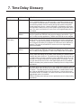
TIME DELAY GLOSSARY . . . . . . . . . . . . . . . . . . . . . . . . . . . . . . . . . . . . . . . . . . . .
PAGE
6-5
6-5
6-7
6-7
6-7
6-7
6-7
6-7
6-7
6-7
7-1
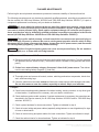
WARNING
INCORRECT SERVICE OR REPLACEMENT OF PARTS CAN RESULT IN
DEATH, SEVERE PERSONAL INJURY, AND/OR EQUIPMENT DAMAGE. SERVICE PERSONNEL MUST BE QUALIFIED TO PERFORM ELECTRICAL AND/
OR MECHANICAL SERVICE.
iv
Redistribution or publication of this document,
by any means, is strictly prohibited.
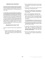
Safety Precautions
1. Move the operation selector switch on the generator set to Stop.
This manual includes the following symbols to indicate potentially dangerous conditions. Read the
manual carefully and know when these conditions
exist. Then take the necessary steps to protect personnel and the equipment.
2. Disconnect the battery charger.
3. Disconnect the starting batteries of the generator set or sets (remove the ground [–] lead first).
DANGER This symbol warns of immediate
hazards that will result in severe personal injury
or death.
4. Remove AC power to the automatic transfer
switch. If the instructions require otherwise,
use extreme caution due to the danger of
shock hazard.
WARNING This symbol refers to a hazard or
unsafe practice that can result in severe personal injury or death.
UTILITY-TO-UTILITY APPLICATIONS
This symbol refers to a hazard or
unsafe practice that can result in personal injury or product or property damage.
CAUTION
If the cabinet must be opened for any reason, remove AC power to the automatic transfer switch. If
the instructions require otherwise, use extreme
caution due to the danger of shock hazard.
ELECTRICAL SHOCK CAN CAUSE
SEVERE PERSONAL INJURY OR DEATH
GENERAL PRECAUTIONS
High voltage in transfer switch components presents serious shock hazards that can result in severe
personal injury or death. Read and follow these
suggestions.
Keep the transfer switch cabinet closed and locked.
Make sure only authorized personnel have the cabinet and operational keys.
Due to the serious shock hazard from high voltages
within the cabinet, all service and adjustments to
the transfer switch must be performed only by an
electrician or authorized service representative.
Place rubber insulative mats on dry wood platforms
over metal or concrete floors when working on any
electrical equipment. Do not wear damp clothing
(particularly wet shoes) or allow skin surfaces to be
damp when handling any electrical equipment.
Jewelry is a good conductor of electricity and
should be removed when working on the electrical
equipment.
Wear safety glasses whenever servicing the transfer switch and and do not smoke near the batteries.
Do not work on this equipment when mentally or
physically fatigued, or after consuming alcohol or
any drug that makes the operation of equipment unsafe.
UTILITY-TO-GENSET OR GENSET TO
GENSET APPLICATIONS
If the cabinet must be opened for any reason:
WARNING
INCORRECT SERVICE OR REPLACEMENT OF PARTS CAN RESULT IN
DEATH, SEVERE PERSONAL INJURY, AND/OR EQUIPMENT DAMAGE. SERVICE PERSONNEL MUST BE QUALIFIED TO PERFORM ELECTRICAL AND/
OR MECHANICAL SERVICE.
OTPC-2
v
Redistribution or publication of this document,
by any means, is strictly prohibited.
THIS PAGE LEFT INTENTIONALLY BLANK
vi
Redistribution or publication of this document,
by any means, is strictly prohibited.
1. Introduction
3.
4.
5.
6.
OPERATOR’S MANUAL
This manual covers models produced under the
Cummins/Onan and Cummins Power Generation brand names.
Transfers the load to the Source 2.
Senses the return of Source 1.
Retransfers the load to Source 1.
Sends a stop signal to the generator set.
UTILITY-TO-UTILITY OPERATION
This operator’s manual provides information necessary for operation of an OTPC transfer switch.
This is an open transition (OT) transfer switch with
PowerCommand Control (PC). With an open transition switch there is never a time when both
sources are supplying power to the load.
In utility-to-utility applications, the transfer switch
performs the following functions:
1.
2.
3.
4.
Programmed transition switches pause in the neutral position of the transfer switch, between
switched positions, so that transient currents from
the load can diminish before the load is switched to
the other source.
Senses the interruption of the Source 1 power.
Transfers the load to the Source 2.
Senses the return of Source1.
Retransfers the load to Source 1.
NORMAL
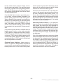
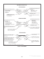
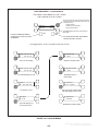
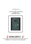
TRANSFER SWITCH APPLICATION
OVERCURRENT
PROTECTIVE
DEVICE
Transfer switches are an essential part of a building’s standby or emergency power system. Power
Source 1 (Normal), commonly the utility line, is
backed up by Power Source 2 (Emergency), often a
generator set. The transfer switch automatically
switches the electrical load from one source to the
other.
The load is connected to the common of the transfer
switch (Figure 1-1). Under normal conditions, the
load is supplied with power from Source 1 (as illustrated). If Source 1 is interrupted, the load is transferred to Source 2. When Source 1 returns, the load
is retransferred to Source 1. The transfer and retransfer of the load are the two most basic functions
of a transfer switch.
LOAD
Automatic transfer switches, capable of automatic
operation without operator intervention, perform the
following basic functions:
OVERCURRENT
PROTECTIVE
DEVICE
UTILITY-TO-GENSET OPERATION
In utility-to-genset applications, the transfer switch
performs the following functions:
EMERGENCY
1. Senses the interruption of the Source 1 power.
2. Sends a start signal to the generator set
(Source 2).
FIGURE 1-1. LOAD TRANSFER SWITCH
(TYPICAL FUNCTION)
1-1
Redistribution or publication of this document,
by any means, is strictly prohibited.
is the backup genset. An external power supply is
not needed in this application.
GENERATOR-TO-GENERATOR CONTROL
The genset-to-genset control can be set up for two
types of applications:
Preferred Source Selection – Under normal operation, one genset is designated as the preferred
source and supplies power to the load. The second
genset is the backup power source. If the preferred
genset fails, the backup genset starts and the transfer switch transfers the load to the backup genset.
• Prime Power – Two gensets provide all of the
power (utility power is not available)
• Dual Standby – Two gensets are used to
back up utility power
At any time, the PC Service tool or the Test submenu can be used to designate either genset
(Source 1 or Source 2) as the preferred genset. If
the preferred genset is changed and the backup
genset becomes the preferred genset, the transfer
switch transfers the load to the new preferred genset when it becomes available. The unit that is carrying the load is always considered the preferred
source.
Note: The Test/Exercise function and Load Shed
feature are not available in this configuration.
If one genset fails to operate within the specified
range of voltage and frequency, the transfer switch
automatically starts and connects the other genset.
Preferred Source Selection
With both prime power and dual standby applications, either genset can be set up to be the preferred
source. If the preferred source is changed while one
of the gensets is running, the control starts the second genset and transfers the load to it, when it becomes available.
Automatic Changeover – The transfer switch can
be set up to change the preferred source automatically by enabling the changeover timer. The Time
Delay sub-menus under Setup or the PC Service
tool can be used to enable the changeover timer
and specify a changeover delay time period.
Time Delays
TDNE
10 SEC
TDEN
600 SEC
TDESa
3 SEC
TDECa
600 SEC
The automatic changeover timer automatically
changes the preferred source and transfers the
load to the new preferred genset after a TDEN time
delay. After the transfer is complete, the control initiates a cool-down period (TDEC) on the old preferred genset before shutting it down. The old preferred genset is now the new backup genset. The
changeover timer is now timing for the next changeover and the cycle continues as long as the changeover timer is enabled.
TDESb
3 SEC
Dual Stand-By Operation
TDECb
600 SEC
All the time delays are factory set and are adjustable through the front panel display. The factory settings are:
In dual stand-by applications, utility power is available. The system includes two transfer switches
and two gensets. Utility power supplies power to the
load and both gensets are backup gensets.
Note: TDESa and TDECa are for the Source 2 genset and TDESb and TDECb are for the Source 1
genset.
Under normal operation, the utility is supplying power to the load through the lead transfer switch. The
lead transfer switch is a utility-to-genset switch. The
two gensets are connected to the genset-to-genset
transfer switch. The load side of this switch is connected to the genset side of the lead transfer switch.
Use the Time Delay sub-menus under Setup or the
PC Service tool to change the settings.
Prime Power (Plant to Plant) Operation
In prime power applications, utility power is not
available. The system includes one transfer switch
and two gensets. One genset is always running and
supplying power to the load while the other genset
Upon loss of utility power to the lead transfer switch,
a signal is sent to the genset-to-genset transfer
switch to start the preferred genset. When the lead
1-2
Redistribution or publication of this document,
by any means, is strictly prohibited.
and the preferred genset fails, the backup genset
starts and the genset-to-genset transfer switch
transfers the load to the backup genset.
transfer switch senses generator voltage, it transfers the load to that genset. If the preferred genset
fails to start, a signal is sent to the backup genset to
start. The PC Service tool or the Test sub-menu on
the genset-to-genset transfer switch can be used to
set the preferred source.
At any time, the PC Service tool or the Test sub–
menu on the genset-to-genset transfer switch can
be used to designate either genset (Source 1 or
Source 2) as the preferred genset. If the preferred
genset is changed and the backup genset becomes
the preferred genset, the transfer switch transfers
the load to the new preferred genset if it is needed
and when it becomes available.
If the Stand-By Start is inactive, upon initial power–
up (or reset), or during software initialization, the
transfer switch control will not start either genset.
When a Stand-By Start command is received from a
Master ATS (or other device), the preferred genset
immediately starts. If the preferred genset does not
start, a time delay engine start (TDES) is initiated
and the control starts the backup genset. The load
is connected to the genset when it becomes available.
Alternating Preferred Source – In an attempt to
keep the running time equally distributed between
both gensets, the control can be set to alternate between the gensets when utility power fails. The selected preferred genset starts with the first power
outage. The second power outage starts the backup genset, which now becomes the preferred genset. Upon subsequent outages, the preferred genset alternates.
If the preferred genset becomes available while the
backup genset is active, a time delay retransfer
(TDEN) period is initiated and the load is retransferred back to the preferred genset. A time delay
cool-down (TDEC) period is initiated before turning
off the backup genset. When the Stand-By Start becomes deactivated, a TDEC period is initiated and
the active generator is turned off.
Only utility outages and tests or exercises initiated
at the lead transfer switch result in the gensets being alternated. The designated preferred genset will
not change if it fails and the backup genset takes
over the load. This alternating preferred source can
only be enabled with the PC Service tool. When enabled, a genset can be designated as the preferred
source for a maximum of two weeks. Time adjustments can be made in one-hour increments.
Preferred Source Selection – Under normal operation, one genset is designated as the preferred
source and the second genset is designated as the
backup power source. If the both the utility power
1-3
Redistribution or publication of this document,
by any means, is strictly prohibited.
E = 1200
F = 1600
G = 2000
H = 3000
CONTROL LEVEL 1 AND LEVEL 2
Two controls are available. The type of power
source switched and the desired features determine the control levels available. See the Description section for details. The table lists the applications that are available with each control.
3. Assigned spec number - issued for each specific combination of accessories, voltages, frequency and standards codes. This number is
only repeated for standard product.
TABLE 1-1. AVAILABLE CONTROL LEVELS
Power Sources
Level 1
Level 2
Genset-to-Utility
X
X
Genset-to-Genset
X
Utility-to-Utility
X
4. Specification letter - advances with production
modification.
HOW TO OBTAIN SERVICE
When the transfer switch requires servicing, contact your nearest Cummins Power Generation distributor. Factory-trained Parts and Service representatives are ready to handle all your service
needs.
MODEL IDENTIFICATION
Identify your model by referring to the Model and
Specification number as shown on the nameplate.
Electrical characteristics are shown on the lower
portion of the nameplate, which is located on the
cabinet door.
To contact your local Cummins Power Generation
distributor in the United States or Canada, call
1-800-888-6626 (this automated service utilizes
touch-tone phones only). By selecting Option 1
(press 1), you will be automatically connected to the
distributor nearest you.
If it is necessary to contact a distributor regarding
the transfer switch, always give the complete Model, Specification, and Serial number. This information is necessary to properly identify your unit
among the many types manufactured.
If you are unable to contact a distributor using the
automated service, consult the Yellow Pages. Typically, our distributors are listed under:
The model number is made up of code segments
that designate various features or options:
OTPCA 00000
|
|
|
1 2
3
Generators-Electric,
Engines-Gasoline or Engines-Diesel, or
Recreational Vehicles-Equipment,
Parts and Service.
Spec.A
|
4
For outside North America, call Cummins Power
Generation, 1-763-574-5000, 7:30 AM to 4:00 PM,
Central Standard Time, Monday through Friday. Or,
send a fax to Cummins Power Generation using the
fax number 1-763-574-8087.
1. OTPC - Open Transition PowerCommand
Control.
2. Ampere Rating:
A = 40, 70, 125
B = 150, 225, 260
C = 300, 400, 600
D = 800, 1000
When contacting your distributor, always supply the
complete Model, Specification, and Serial Number
as shown on the generator set nameplate.
Copyright 2002 Cummins Power Generation. All rights reserved.
Cummins, Onan and PowerCommand are registered trademarks of Cummins Inc.
1-4
Redistribution or publication of this document,
by any means, is strictly prohibited.
2. Description
The OTPC transfer switch is available in two control
package options: Level 1 and Level 2. Level 1 has
the standard feature set and Level 2 has an extended set of features and applications. This section describes the standard and optional control
features.
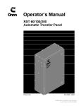
CABINET
The standard cabinet meets the requirements for a
UL Type 1 cabinet. This type is designated as a general-purpose, indoor cabinet. Figure 2-1 shows the
control with optional features.
BAR GRAPH
METER PANEL
(LEVEL 1 NA,
LEVEL 2 OPTIONAL)
SWITCH PANEL
(STANDARD)
OPTIONAL
KEY SWITCH
DIGITAL DISPLAY
(LEVEL 1 OPTIONAL
LEVEL 2 STANDARD)
FIGURE 2-1. CABINET WITH OPTIONS
2-1
Redistribution or publication of this document,
by any means, is strictly prohibited.
cise Active indicator goes out and Source 1 resumes as the source of power.
CONTROL PANEL
The control features are divided into three groups:
Bar Graph Meters, Switch Panel, and Digital Display. The Switch Panel is standard on all transfer
switches. The Digital Display is standard on Level 2
controls and is optional on Level 1 controls. The Bar
Graph Display is not available on Level 1 and is optional on Level 2 controls.
For genset-to-genset applications, there is no test
function.
Override: The Override switch terminates most
system time delays. The Program Transition, Elevator signal and Engine Cool Down are not affected
by this switch. If you press this switch while the
Transfer Inhibit input is active, the switch immediately transfers the load. If you press this switch
while the Retransfer Inhibit input is active, the
switch immediately retransfers the load.
Switch Panel
The switch panel (See Figure 2-1) is a standard feature on all OTPC transfer switches. It contains six indicator lamps and three membrane switches.
Reset/Lamp Test: The Reset/Lamp Test switch
turns on all control panel indicators. This switch also
acknowledges events (refer to the Events section).
Source 1 Available and Source 2 Available:
These indicators are lit when the corresponding
sources have acceptable output voltage and/or frequency. These indicators can be lit simultaneously.
Security Key Switch Option
The optional security key switch is located on the
front panel between the handle and the Control
Panel. When it is in the Panel Lock position, it disables the front panel input switches, Test and Override. It also prevents changes to the Digital Display
from the setup menus; however, the current values
are displayed. Changes can be made when the
switch is in the Program position.
Source 1 Connected: This indicator is lit when the
transfer switch is in the normal position and Source
1 is supplying power to the load.
Source 2 Connected: This indicator is lit when the
transfer switch is in the emergency position and
Source 2 is supplying power to the load.
Not in Auto: For all configurations, the Not in Auto
indicator lights when the transfer switch is not in
Auto.
Digital Display
The Digital Display is standard on Level 2 controls
and optional on Level 1 controls. It contains a 2-line
by 20-character digital display module and 6 momentary contact membrane switches. The module
displays the menu system. The switches are used
to navigate through the menu system.
The transfer switch is not in auto when any of the following signals are active:
1. Motor Disconnect Switch
2. Transfer Inhibit
Each menu indicates the function of the four
switches at the sides of the display module. Not all
switches are active for each menu. See the Digital
Display Menu System section for complete digital
display menu details.
3. Retransfer Inhibit
4. Load Shed
Test/Exercise Active: The Test/Exercise Active indicator is lit when the transfer switch has a test or
exercise in progress.
Bar Graph Meter Panel
The Bar Graph Meter Panel is not available on Level 1 controls and is optional on Level 2 controls. This
feature includes a three phase AC ammeter, a power meter, a power factor meter, a frequency meter,
and a three phase AC voltmeter.
Test: For utility-to-genset applications, the Test
switch sends a start signal to the generator set designated Source 2 and blinks the Test/Exercise Active indicator. After the start and transfer time delays, Source 2 starts and assumes the load provided that the With Load option is selected. Press
the Test switch again to end the test; the Test/Exer-
AC Ammeter: The ammeter displays percent of full
load currents in amperes (1–125%).
2-2
Redistribution or publication of this document,
by any means, is strictly prohibited.
Power Meter: The power meter displays the real
power in percent of full load in kilowatts (0–125%).
control system starts the generator. The value is set
with the PC service tool or the digital display when it
is available.
Power Factor Meter: The power factor meter displays the real power delivered to the load (1.0 – 0.6
lagging) and (1.0 – 0.9 leading).
For genset-to-genset applications, TDES-A is the
start time delay to start Source 2 genset and TDESB is the start time delay to start Source 1 genset.
Frequency Meter: This meter displays the output
frequency (percent of nominal frequency), of the
power source connected to the load (70–110%).
For utility-to-utility applications, TDES-A and
TDES-B are not available.
AC Voltmeter: The voltmeter displays percent of
line to neutral voltages of the power source connected to the load (70–110%).
Stop Time Delay (TDEC-A, and TDEC-B): This
delay is adjustable from 0 to 30 minutes in 1 minute
increments. The default value is 10 minutes. It begins timing when the load is retransferred to Source
1. At the end of the delay, the stop signal is sent to
the generator set. During this time delay, the generator set cools down at no load before stopping. The
value is set with the PC service tool or the digital display when it is available.
ELECTRONIC CONTROL SYSTEM
This section describes the standard and optional
components of the electronic control system.
WARNING Improper calibration or adjustment
of electronic control modules can cause death,
severe personal injury, and equipment or property damage. Calibration and adjustment of
these components must be performed by technically qualified personnel only.
For genset-to-genset applications, TDEC-A is the
stop time delay to stop Source 2 genset and TDECB is the stop time delay to stop Source 1 genset.
For utility-to-utility applications, TDEC-A and
TDEC-B are not available.
All calibration and adjustment procedures are described in the Installation manual (which is shipped
with the transfer switch) and in the Service manual
(which is available through your distributor).
Transfer Time Delay (TDNE): This delay begins
when Source 2 (typically the generator) voltage and
frequency reach the settings of the control. After the
delay, the transfer switch transfers the load to
Source 2. This brief time delay allows the generator
set to stabilize before the load is applied. It has an
adjustable range of 0 to 120 seconds in 1 second increments. The default value is 10 seconds. The value is set with the PC service tool or the digital display when it is available.
Accidental actuation of the linear
motor could cause severe personal injury. Before making any adjustments, place the Motor
Disconnect Switch (Figure 1-7) in the Off position. Return the switch to the Auto position after
adjustments are completed.
WARNING
AC power within the cabinet and the
rear side of the cabinet door presents a shock
hazard that can cause severe personal injury or
death. When the cabinet door is open, use extreme caution to avoid touching electrical contacts with body, tools, jewelry, clothes, hair, etc.
WARNING
TDNE is the delay from preferred source to backup
source in utility-to-utility applications.
Retransfer Time Delay (TDEN): This delay begins
the moment Source 1 line voltage and frequency return to specified values. After the delay, the transfer
switch can retransfer the load to Source 1. The
delay allows the Source 1 to stabilize before retransfer. It has an adjustable range of 0 to 30 minutes in
1 minute increments. The default value is 10 minutes. The value is set with PC service tool or the digital display when it is available.
Start Time Delay (TDES-A, and TDES-B): This
delay is adjustable from 0 to 15 seconds in 1 second
increments on Level 1 controls and from 0 to 120
seconds in 1 second increments on Level 2 controls. The default value is 3 seconds for both. This
brief time delay prevents the generator set from
starting during short power interruptions. Timing
starts at the Source 1 power interruption. If the
duration of interruption exceeds the delay time, the
TDEN is the delay from backup source to preferred
source in utility-to-utility applications.
2-3
Redistribution or publication of this document,
by any means, is strictly prohibited.
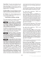
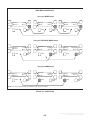
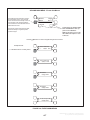
Under-Voltage Sensing
Example using Default Settings
for Nominal Voltage of 240 VAC
All controls include under-voltage sensors for
Source 1 and Source 2. When a sensor detects a
low voltage condition over a specified time period, it
initiates a transfer. When the source voltage returns
to an acceptable value again, the sensor initiates a
retransfer.
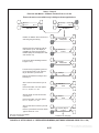
These parameters are adjustable. The under-voltage sensing range for a falling voltage (drop-out) is
75 to 98% of the pick-up voltage setting. The default
value is 90%. The pick-up range for a rising voltage
is 85 to 100% of the nominal voltage setpoint. The
default value is 90%. The adjustable range for the
time delay period is 0.1 to 1.0 seconds in 0.1 second
increments. The default delay time is 0.5 second.
These values are set with the PC service tool or the
digital display. See Figure 2-2 for an example using
the default values.
Drop-out
Setting
(194V)
Pick-up
Setting
(216V)
90% of
Pick-up
90% of
Nominal
Nominal
Setpoint
(240V)
VOLTS
FIGURE 2-2. UNDER-VOLTAGE SENSING
Over-Voltage Sensing
All controls include over-voltage sensors for
Source 1 and Source 2 that can be disabled and not
used. When a sensor detects a high voltage condition over a specified time period (delay), it initiates a
transfer. When the source voltage falls to an acceptable value again, the sensor initiates a retransfer.
Example using Default Settings
for Nominal Voltage of 240 VAC
Nominal
Setpoint
(240V)
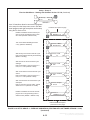
There parameters are adjustable. The over-voltage
sensing range (drop-out) for a rising voltage is 105
to 135% of the nominal voltage setpoint. The default
value is 110%. The pick-up range for a falling voltage is 95 to 100% of the drop-out setting. The default value is 95%. The adjustable range for the
delay time period is 0.5 to 120.0 seconds in 1 second intervals. The default delay time is 3.0 seconds. The over-voltage sensing feature is enabled
by default. These values are set with the PC service
tool or the digital display. See Figure 2-3 for an example using the default values. This feature can
also be disabled.
Pick-up
Setting
(251V)
Drop-out
Setting
(264V)
95% of
Drop-out
110% of
Nominal
VOLTS
FIGURE 2-3. OVER-VOLTAGE SENSING
2-4
Redistribution or publication of this document,
by any means, is strictly prohibited.
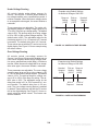
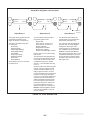
Frequency Sensing
Example using Default Settings
for Nominal Frequency of 60 Hz
All controls include frequency sensors for Source 1
and Source 2 that can be disabled and not used.
When a sensor detects a high or low frequency condition over a specified delay time period, it initiates a
transfer. When the frequency returns to an acceptable value again, the sensor initiates a retransfer.
60 Hz
These parameters are adjustable. The nominal frequency can be set between 45.0 and 60.0 Hz in
0.1 Hz increments. The default frequency is 60 Hz.
The acceptable frequency bandwidth (pick-up) is
±5 to ±20% of the nominal frequency setpoint. The
default value is 10%. The drop-out frequency is 1 to
5% beyond the pick-up. The default value is 1%.
The range for the delay time period is 0.1 to 15 seconds. The default delay time is 1.0 second. The frequency sensing feature is enabled by default.
These values are set with the PC service tool or the
digital display. See Figure 2-4 for an example using
the default values. This feature can also be disabled.
Pick-up Frequencies
54 Hz
66 Hz
Drop-out Frequencies
66.7 Hz
53.5 Hz
FIGURE 2-4. FREQUENCY SETTING
Programmed Transition
Program Transition introduces a delay (TDPT) during transition of the switch. Programmed transition
stops the switch in the neutral position for an adjustable interval of time. In this position, the load is not
connected to either Source 1 or 2. This delay allows
residual current from inductive loads to decay to an
acceptable level before transfer is completed.
Two-Wire Starting
The starting circuit is a basic supervisory function of
the electronic control. Water-cooled generator sets
use a two-wire start control.
Although the logic is more involved, the two-wire
starting circuit can be thought of as a single pole,
single throw switch. A closed switch starts the generator set. An open switch stops the generator.
The parameters are adjustable. The length of time
that the transfer switch is in the neutral position can
be adjusted from 0 to 60 seconds in 1 second increments. The default value is 0 seconds. The proper
adjustment is a function of the load. This feature is
enabled by default. The values are set with PC service tool or the digital display.
Three-wire starting is not available on OTPC transfer
switches.
Remote Test Transfer
Transfer Times
The transfer switch may be wired with a remote test
switch. Closure of a set of contacts across the remote test transfer inputs causes the transfer switch
to sense a (simulated) utility power failure and send
a start/run signal to the generator set. The load is
transferred to Source 2 when Source 2 becomes
available. (Refer to the Installation manual.)
The controller senses and records the time it takes
for the transfer switch to break from one source and
reconnect to the other source. (Transfer times are
not recorded if Programmed Transition delay is in
use.)
2-5
Redistribution or publication of this document,
by any means, is strictly prohibited.
This feature informs the operator when there is significant voltage imbalance between the phases of
Source 1 or Source 2. This feature is used for equipment protection.
Test With or Without Load
The operator can test the transfer switch, generator,
and power system automatically. The operator can
transfer the load during the test or only test the generator. Both hardware means (switch input) and
software means (PowerCommand network) input
can activate an automatic test sequence.
A voltage imbalance is typically caused by severe
single phase loading. The sensor indicates a failure
when the maximum deviation from the average voltage is greater than a user-specified value between
2 and 10% (drop-out) of the average voltage in 1%
increments. The pickup value is fixed at 10% of the
drop-out. The time delay for the imbalance sensor
drop-out is adjustable (2–20 seconds).
Programmable Generator Exerciser
Programmable generator exercises and exercise
exceptions are generally programmed to be recurring. They can be programmed from the PC service
tool or the digital display when it is available.
This sensor can be enabled using the PC Service
tool or the digital display Setup sub-menus. This
sensor is inactive for single phase systems and indicates no failures. To prevent nuisance faults, the
setting can be increased up to 10% of the nominal
voltage.
Level 1 controllers include two programmable generator exercises and two programmable exercise
exceptions. While all events can be set using the PC
service tool, only one exercise and one exercise exception can be set with the digital display.
Phase Rotation Sensor
Level 2 controllers include eight programmable
generator exercises and eight programmable exercise exceptions. While all events can be set using
the PC service tool, only two exercises and two exercise exceptions can be set with the digital display.
All controllers have a push-button switch on the digital module that enables and disables the exerciser
clock. See the Digital Display Menu System section
for details on setting the clock. The Real-Time clock
must be set before exercise programs are entered.
Three phase Level 2 controllers include a phase
rotation sensor. This feature monitors the phase
rotation of the source opposite from the connected
source. When the alternate source is out of phase
rotation with the connected source, transfer is inhibited. This generally occurs on new installations or
after storm damage or generator rewiring. This feature protects against equipment damage by preventing transfer to a source that is out of phase. This
feature is required in fire pump applications.
For utility-to-genset configurations, the exerciser
clock initiates genset start and run cycles at specified intervals for specified durations. The exerciser
is not used in utility-to-utility or genset-to-genset
configurations (see Generator-to-Generator Control Mode).
CAUTION Level 1 controls do not support
three-phase sensing on Source 2. Do not select
the three-phase option for the Source 2 Sensing
adjustment with Level 1 controls, even if the
system is three phase. This setting will prevent
Source 2 from becoming available.
Real-Time Clock
Both voltage sources have to be applied in order to
check phase rotation. Generally, a power source
may become out of phase rotation in new installations, after a storm, or when there is generator rewiring.
All controllers have a real-time clock that keeps
track of the time and date. This clock is year 2000
compliant. The controller uses the real-time clock to
time and date stamp all events.
The clock is not set at the factory. To set the clock,
use the digital display or PC Service tool.
This feature is enabled by default. It can be disabled
using the PC Service tool or the digital display Setup
sub-menus.
Voltage Imbalance Sensor
Loss of Single Phase Sensor
Three phase Level 2 controllers include a voltage
imbalance sensor for both Source 1 and Source 2.
Three phase Level 2 controllers include a loss of
single phase sensor. This feature initiates a transfer
2-6
Redistribution or publication of this document,
by any means, is strictly prohibited.
from a source that has lost a single phase and prevents a transfer to a source that has lost a single
phase. This is generally caused by a single phase to
line ground or open. The controller indicates a fault
when the relative phase angle between any line-toline phase angle drops to less than 90 degrees. This
feature is mainly used to protect three phase devices, such as motors.
reactivated when an event occurs or when an operator touches one of the menu buttons.
In order to conserve controller battery power, the
loss of utility power also causes the digital display to
go blank. The digital display is reactivated when a
second power source becomes available.
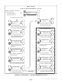
TRANSFER SWITCH
This sensor can be enabled using the PC Service
tool or the digital display Setup sub-menus. This
sensor is inactive for single phase systems and indicates no failures.
The transfer switch (Figures 2-5 and 2-6) opens and
closes the contacts that transfer the load between
Source 1 and Source 2. The switch is mechanically
interlocked to prevent simultaneous closing to both
power sources. The main parts of the switch discussed here are the contact assemblies, linear actuator, Motor Disconnect switch, and auxiliary contacts.
Generator-to-Generator Control Mode
Level 2 controllers can control a two-generator configuration for either dual standby or prime power.
One generator is designated the preferred source.
The default preferred source is Source 1 but it can
be changed to Source 2 through the front panel display or PC service tool. The control automatically
transfers the load between the two generators and
detects generator alarm conditions. This configuration requires the optional Battery Kit when used in
dual standby mode.
Contact Assemblies
The automatic transfer switch has either three or
four poles. Three pole transfer switches are provided with a neutral bar. The contact assemblies
make and break the current flow. When closed to either Source 1 or Source 2, the contacts are mechanically held. A mechanical interlock prevents
them from closing to both power sources at the
same time.
A separate changeover timer automatically transfers loads between the two generators. The
changeover timer is set from the digital display or
the PC Service tool. The exerciser clock is not available in this configuration.
Linear Actuator
The linear actuator is a linear induction motor that
moves the contact assemblies between the contacts of Source 1 and Source 2. Linear actuator operation is initiated automatically by the transfer
switch. Manual operation of the switch is also possible. Refer to Manual Operation.
Utility-to-Utility Control Mode
Level 2 controllers can control a two-utility configuration for prime power. One utility is designated the
preferred source. The default preferred source is
Source 1 but it can be changed to Source 2 through
the front panel display or PC service tool. The control automatically transfers the load between the
two utilities and detects alarm conditions. The exerciser clock is not available in this configuration.
Motor Disconnect Switch
The Motor Disconnect toggle switch, on the Relay
Assembly, enables and disables the linear actuator.
This switch is only accessible from inside the enclosure. The Not In Auto LED on the front panel indicates the state of this switch. It is lit when the switch
is in the Off position. Place the switch in the Auto
position to enable the linear actuator. Place the
switch in the Off position to disable the linear actuator.
Sleep Mode
After a period of screen inactivity (35 minutes), the
digital display goes blank. Screen inactivity is when
there is no user interaction with the menu system
and when there are no events. The digital display is
2-7
Redistribution or publication of this document,
by any means, is strictly prohibited.
tact switch is actuated when the transfer switch is in
the Source 1 position. The Source 2 auxiliary contact switch is actuated when the transfer switch is in
the Source 2 position. The auxiliary contacts have
current ratings of 10 amperes at 250 VAC. The contacts are wired to terminal block TB1.
Auxiliary Contacts
Auxiliary contacts are provided on the Source 1 and
Source 2 sides of the transfer switch. They are actuated by operation of the transfer switch during
transfer and retransfer. The Source 1 auxiliary con-
OPTIONAL BATTERY
CHARGER
BAR GRAPH
ASSEMBLY
NETWORK
COMMUNICATIONS
MODULE
CONTROLLER
BATTERIES
PC SERVICE
TOOL CONNECTOR
TB1
AUTOMATIC
TRANSFER
SWITCH
NETWORK
BATTERIES
DIGITAL
MODULE
P1 POWER
(CONTROL)
DISCONNECT
RELAY
ASSEMBLY
MOTOR DISCONNECT
SWITCH (S1)
DIGITAL
DISPLAY
TB2
POWER
MODULE
TRANSFER
SWITCH
HANDLES
FIGURE 2-5. INTERIOR/COMPONENTS: 40-125 AMP SWITCH
2-8
Redistribution or publication of this document,
by any means, is strictly prohibited.
DIGITAL MODULE
NETWORK
COMMUNICATIONS
MODULE
CONTROLLER
BATTERIES
BAR GRAPH
ASSEMBLY
PC SERVICE
TOOL
CONNECTOR
TB1
NETWORK
BATTERIES
TRANSFER
SWITCH
HANDLE
POWER
MODULE
DIGITAL
DISPLAY
MOTOR DISCONNECT
SWITCH
RELAY ASSEMBLY
TB2
OPTIONAL BATTERY
CHARGER
AUTOMATIC TRANSFER
SWITCH
FIGURE 2-6. INTERIOR/COMPONENTS: 1200 AMP SWITCH
2-9
Redistribution or publication of this document,
by any means, is strictly prohibited.
OPTIONS
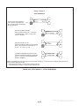
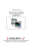
Float Battery Charger Option
A float-charge battery charger (Figure 2-7) regulates its charge voltage to continuously charge without damage to the battery. As the battery approaches full charge, the charging current automatically tapers to zero amperes or to steady-state load
on the battery.
Two chargers are available. One battery charger is
rated for 10 amperes at 12 or 24 VDC. The other
battery charger is rated for 2 amperes at 12 or
24 VDC.
SC1613
ES1692
2-AMP CHARGER
10-AMP CHARGER
FIGURE 2-7. BATTERY CHARGER
The 2-ampere battery charger has an ammeter to
indicate charging current and a fuse to protect the
battery charger circuit.
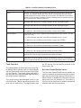
Relay Signal Module Option
The Relay Signal Module includes 11 Form-C relay
contacts. The module includes the Elevator PreTransfer Delay Signal. The relay contacts may be
used with other applications.
The 10-ampere battery charger has three fuses
(two on the AC input and one on the DC output),
three fault display LEDs, and an ammeter for indication of charging current.
TABLE 2-1. RELAY SIGNAL MODULE
On the 10-ampere charger, three sets of (form C)
alarm contacts (corresponding to the three fault
LEDs) are also available. Using an optional alarm
contact harness, these contacts can be wired by the
installer to activate other audible or visual alarms.
Relay Signal
Under normal operating conditions, the Low Bat
and AC Fail relays are energized and the High Bat
relay is de-energized. In response to a Low Bat or
AC Fail condition, the appropriate normally energized relay (Low Bat or AC Fail) drops out. In response to a High Bat condition, the normally de-energized High Bat relay is energized.
Level 1 & 2
Source 1 Connected
X
Source 1 Available
X
Source 2 Connected
X
Source 2 Available
X
Test Active
X
Transfer Switch Not In Auto
X
Elevator Pre-Transfer
X
Load Shed Active
X
Fail to Close
Not Used
Auxiliary Relay Option
The Elevator Pre-Transfer Delay Signal delays
transfer (or retransfer) for a specified time to give
warning to an elevator control that a transfer (or retransfer) is about to occur.
Optional DC auxiliary relays provide contacts for
energizing external alarms, remote indicators, and
control equipment such as louver motors and water
pumps.
This time delay is adjustable over a range of 0 to 60
seconds. The default value is 0 seconds. The value
is set with the PC service tool or the digital display
when it is available.
2-10
Redistribution or publication of this document,
by any means, is strictly prohibited.
ter the preceding variable. The network variables
are intended to activate relays on the Network Digital Input/Output Module (DIM). The DIM is located
remotely from the transfer switch.
Load Shed Option
The optional Load Shed function is used to disconnect the load from an available Power Source 2 in
order to reduce the power consumed from that
source. When the load shed function is initiated, the
transfer switch is moved to the neutral position and
the Not In Auto indicator lights.
Load Current and Power Sensor Option
Three-phase Level 2 controllers can include a load
current and power sensor (Current Module). The
control senses the four load currents (three line currents and the neutral current), three load voltages,
and three power factor angles. The control calculates the real load power and the apparent load
power.
When load shedding is active and Power Source 1
returns, the control immediately retransfers to Power Source 1.
If the load shed signal is removed before Power
Source 1 returns, the switch transfers back to Power Source 2.
The load current sensing feature is active on Level 2
controllers when the Current Module is installed
and connected to the Digital Module.
Load Shed is enabled or disabled from the PC Service Tool or the digital display when it is available.
The control issues a warning when the neutral current exceeds a user specified value between 100
and 150% of the rated current during a specified
time period between 10 and 60 seconds.
Load Sequencing Option
Controllers can include up to eight timed network
variables to use for turning on loads in sequence after a transfer, a retransfer, or both. The Network
Communications Module (NCM) must be installed.
Each variable can be delayed up to 60 seconds af-
The warning threshold (100 – 150%) and time delay
(10 – 60 sec) are only set with the PC Service tool.
2-11
Redistribution or publication of this document,
by any means, is strictly prohibited.
THIS PAGE LEFT INTENTIONALLY BLANK
2-12
Redistribution or publication of this document,
by any means, is strictly prohibited.
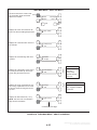
3. Operation
Retransfer - from Source 2 to Source 1:
AUTOMATIC OPERATION
Place control switches in the positions given below.
C. Pull the lower manual operator handle up.
• Motor Disconnect switch: Auto position.
D. Push the upper manual operator handle
up.
For utility-to-genset and genset-to-genset configurations, the generator set control must also be set
for automatic (Auto) operation.
4. Before moving the Motor Disconnect switch
back to the Auto position, remember the transfer switch transfers the load to the active power
source. (If both power sources are available, it
transfers the load to the Source 1.)
For transfer switches equipped with the Digital Display, read through the Digital Display Menu System
section and become familiar with its use.
MANUAL OPERATION OF 40 TO 1000 AMP
TRANSFER SWITCHES
WARNING Automatic transfer switch operation results in rapid movement of the
manual operator handles and presents a
hazard of severe personal injury. Keep
hands clear of handles when switching
back to automatic operation.
The transfer switch has operator handles for manually transferring the load. Manual operation must be
performed by qualified personnel under NO-LOAD
CONDITIONS ONLY. Use the following procedure:
5. Move the Motor Disconnect switch to the Auto
position.
Manual operation of the transfer
switch under load presents a shock hazard that
can cause severe personal injury or death. Do
not attempt to operate switch manually when it
is under load. Follow the “Safety Related Work
Practices” listed in NFPA 70E.
WARNING
6. Close the cabinet door.
MANUAL OPERATION OF 1200 TO 3000
AMP TRANSFER SWITCHES
1. Open the cabinet door of the automatic transfer
switch.
The transfer switch has operator handles that are
intended for maintenance use only. Manual operation must be performed by qualified personnel under NO-LOAD CONDITIONS ONLY. Use the following procedure:
2. Move the Motor Disconnect switch to the Off
position.
3. Transfer - from Source 1 (Normal) to
Source 2 (Emergency):
Manual operation of the transfer
switch under load presents a shock hazard that
can cause severe personal injury or death. Do
not attempt to operate switch manually when it
is under load. Follow the “Safety Related Work
Practices” listed in NFPA 70E.
WARNING
A. Pull the upper manual operator handle
down.
B. Push the lower manual operator handle
down.
3-1
Redistribution or publication of this document,
by any means, is strictly prohibited.
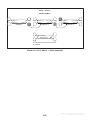
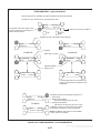
SOURCE 1 (NORMAL) SLOT
TRANSFER SWITCH HANDLE
SOURCE 2 (EMERGENCY) SLOT
FIGURE 3-1. MANUAL OPERATION, 1200-3000 AMP SWITCHES
Manual Transfer to Source 2
WARNING Manual operation of the transfer switch under load presents a shock hazard that can cause severe personal injury or
death. Do not attempt to operate switch
manually when it is under load.
If you determine that Source 2 is available but the
transfer switch does not automatically transfer (refer to the Troubleshooting section), perform this
procedure to manually transfer to Source 2.
1. Open the disconnect switches or breakers that
feed the transfer switch. If there is no Source 2
disconnect, turn off the generator set.
3. A manual operating handle is provided with the
transfer switch. The handle is a steel rod or
tube, with a knob or hand grip on one end. On
standard transfer switches (Figure 3-1), there
are two manual operator slots—one for the
contacts of each power source.
2. When you are certain that neither power
source is supplying power to the transfer
switch, open the transfer switch cabinet door
and turn the Motor Disconnect switch to Off.
First, insert the handle in the slot for the
Source 1 (Normal) contacts and open the
Source 1 contacts. Then, insert the handle in
the slot for the Source 2 (Emergency) contacts
3-2
Redistribution or publication of this document,
by any means, is strictly prohibited.
and close the Source 2 contacts. Be certain to
push the handle all the way to the LOCK position. A distinct over-center locking action can
be felt. Return the handle to its storage position.
WARNING Manual operation of the transfer switch under load presents a shock hazard that can cause severe personal injury or
death. Do not attempt to operate switch
manually when it is under load.
WARNING Automatic transfer switch operation results in rapid movement of the
manual operator mechanism and presents
a hazard of severe personal injury if the operator handle is engaged in the mechanism.
Remove the handle and place it in its storage position.
3. A manual operating handle is provided with the
transfer switch. The handle is a steel rod or
tube, with a knob or hand grip on one end. On
standard transfer switches (Figure 3-1), there
are two manual operator slots—one for the
Source 1 contacts and one for the Source 2
contacts.
4. After the switch has been transferred to Source
2 and the operator handle has been removed
from the mechanism, close and lock the cabinet door.
First, insert the handle into the slot for the
Source 2 (Emergency) contacts and open the
Source 2 contacts. Then, insert the handle into
the slot for the Source 1 (Normal) contacts and
close the Source 1 contacts. Be certain to push
the handle all the way to the LOCK position. A
distinct over-center locking action can be felt.
Return the handle to its storage position.
5. Close the disconnect switches or breakers that
feed the transfer switch. Start the generator set
if it was previously turned off.
WARNING Automatic transfer switch operation results in rapid movement of the
manual operator mechanism and presents
a hazard of severe personal injury if the operator handle is engaged in the mechanism.
Remove the handle and place it in its storage position.
6. If the transfer switch is not functioning correctly,
call your dealer or distributor immediately.
Manual Transfer to Source 1
If you determine that Source 1 is available but the
transfer switch does not automatically retransfer
(refer to the Troubleshooting section), perform this
procedure to manually retransfer to Source 1.
4. After the switch has been transferred to
Source 1 and the operator handle has been removed from the mechanism, close and lock the
cabinet door.
1. Open the Source 2 and Source 1 disconnect
switches or breakers that feed the transfer
switch. If there is no Source 2 side disconnect,
turn off the generator set.
5. Open the Source 2 and Source 1 disconnect
switches or breakers that feed the transfer
switch. Start the generator set if it was previously turned off.
2. When you are certain that neither source is
supplying power to the transfer switch, open
the transfer switch cabinet door and turn the
Motor Disconnect switch to Off.
6. If the transfer switch is not functioning correctly,
call your dealer or distributor immediately.
3-3
Redistribution or publication of this document,
by any means, is strictly prohibited.
2. Press and hold the Test switch for two seconds.
The generator set starts and runs after the start
time delay.
GENERATOR SET EXERCISE
Run the generator for at least 30 minutes once each
week with at least 50 percent load (if possible). If
you do not want to use the exerciser, use the Test
switch, as described below, to test the generator set
each week.
3. At the end of the test period, press the Test
switch again. The generator stops.
4. Reset the Test With/Without Load variable to
the desired value for regularly scheduled genset exercising.
The exerciser can be programmed for specified exercise periods and is used to exercise the generator
set automatically with or without load. If Source 1
has an interruption while the generator set is exercising without load, the automatic transfer switch
transfers the load to the generator set. The PC service tool is required to set the exercise parameters
on transfer switches without the Digital Display. The
Digital Display can set parameters for two exercise
periods and two exceptions and the PC Service
Tool can set parameters for eight exercise periods
and eight exceptions.
WITH-LOAD STANDBY SYSTEM TEST
1. Set the Test With/Without Load variable to the
With Load value (refer to the Digital Display
Menu System section or the PC Service Tool
for details).
The Test With/Without Load variable must be set
to the With Load value in order to test with load.
2. Press and hold the Test switch for two seconds.
The generator set starts and assumes the load
after the start time delay.
GENERATOR SET START TEST
3. At the end of the test period, press the Test
switch again. To bypass the retransfer time
delay and cause immediate load retransfer,
press the Override switch. The generator stops
after the stop time delay.
This test is used with utility-to-genset applications
only.
1. Set the Test With/Without Load variable to the
Without Load value (refer to the Digital Display
Menu System section or the PC Service Tool
for details).
4. Reset the Test With/Without Load variable to
the desired value for regularly scheduled genset exercising.
3-4
Redistribution or publication of this document,
by any means, is strictly prohibited.
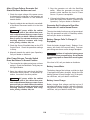
PLANNED MAINTENANCE
Performing the annual planned maintenance procedures increases reliability of the transfer switch.
The following procedures must only be done by technically qualified personnel, according to procedures in the
Service manual (40-1000 Amp Switches: 962-0516 and 1200-3000 Amp Switches: 962-0517). If repair or
component replacement is necessary, call your dealer or distributor.
WARNING AC power within the cabinet and the rear side of the cabinet door presents a shock hazard
that can cause severe personal injury or death. Incorrect installation, service, or parts replacement
can result in severe personal injury, death, and/or equipment damage. All corrective service procedures must be done only by technically qualified personnel, according to procedures in the Service
manual (40-1000 Amp Switches: 962-0516 and 1200-3000 Amp Switches: 962-0517).
WARNING The transfer switch presents a shock hazard that can cause severe personal injury or
death unless all AC power is removed. Be sure to set the genset operation selector switch to Stop,
disconnect AC line power, disconnect the battery charger from its AC power source, and disconnect
the starting battery (negative [–] lead first) before servicing.
Ignition of explosive battery gases can cause severe personal injury. Do not smoke or
cause any spark, arc, or flame while servicing batteries.
WARNING
1. Disconnect All Sources of AC Power:
A. Disconnect both AC power sources from the transfer switch before continuing. Turn the generator
set operation selector switch to Stop. (The selector switch is located on the generator set control
panel.)
B. If there is an external battery charger, disconnect it from its AC power source. Then disconnect the set starting battery (negative [–] lead first).
2. Clean
A. Thoroughly dust and vacuum all controls, meters, switching mechanism components, interior buswork, and connecting lugs.
B. Close the cabinet door and wash exterior surfaces with a damp sponge (mild detergent and water).
Do not allow water to enter the cabinet, especially at meters, lamps, and switches.
3. Inspect
A. Check buswork and supporting hardware for carbon tracking, cracks, corrosion, or any other types
of deterioration. If replacement is necessary, call your dealer or distributor.
B. Check stationary and movable contacts. If contact replacement is necessary, the procedures are
described in the Service manual (for 40-1000 Amp switches: 962-0516 and for 1200-3000 Amp
switches: 962-0517).
C. Check system hardware for loose connections. Tighten as indicated in step 4.
D. Check all control wiring and power cables (especially wiring between or near hinged door) for signs
of wear or deterioration.
E. Check all control wiring and power cables for loose connections. Tighten as indicated in step 4.
F. Check the cabinet interior for loose hardware. Tighten as indicated in step 4.
3-5
Redistribution or publication of this document,
by any means, is strictly prohibited.
4. Perform Routine Maintenance
A. Tighten buswork, control wiring, power cables, and system hardware, as necessary. Hardware
torque values are given in section 4 of the Service manual (for 40-1000 Amp switches: 962-0516
and for 1200-3000 Amp switches: 962-0517). Retorque all cable lug connections. Lug torque requirements are listed in section 1 of the Service manual.
B. Replace the batteries (3V lithium) in the Digital Module and the Network Module (if applicable) every two years. See Figures 2-5 and 2-6.
5. Connect AC Power and Check Operation
A. Connect the set starting battery (negative [–] lead last). Connect the normal AC power source, enable the backup power source. If applicable, connect power to the battery charger.
B. Verify proper operation of the battery charger.
C. Test system operation as described in this section. Close and lock the cabinet door.
3-6
Redistribution or publication of this document,
by any means, is strictly prohibited.
4. Digital Display Menu System
This section describes the Digital Display Menu
System and navigation through the menus. The
menus display status information, events, and setup menus. Setup menus contain parameters with
adjustable values. The descriptions in this section
include ranges for the parameters and default values. The Digital Display is an option with Level 1
controls and is standard with Level 2 controls. See
Figures 2-5 and 2-6. The system menus can also be
accessed with the InPower Service Tool.
menus that list vertical menus (or sub-menus). The
sub-menus display status information. This information cannot be changed in the main menus. The
main menus contain eight sub-menus including the
Setup Menus.
SETUP MENUS
Before you can navigate and change setup parameters, you must enter a password; however, you
can bypass the password and examine but not
change parameters. When parameters are
changed in any setup menu, you are prompted to either save the changes or restore the old values.
Setting and navigating through the password menus is described in Figure 4-7.
The Digital Display Menu System is a 2-line by
20-character graphical display screen and six buttons. The screen or menu displays status information, parameters, events and messages. The buttons change screens and parameters. Two buttons
have names: Home and Previous Menu. These buttons are used for navigation. Messages include
navigational indicators for the other four buttons.
NAVIGATION
Refer to Figures 4-28 through 4-30 at the end of this
section for an overview of menu navigation. These
illustrations can also be used to locate a submenu
and determine how to access it.
MAIN MENUS
The main menu system consists of three top-level
4-1
Redistribution or publication of this document,
by any means, is strictly prohibited.
MAIN MENU NAVIGATION
Using the MORE button
##
##
!" ##
Using the PREVIOUS MENU button
##
##
!" ##
Using the HOME button
##
##
!" ##
NOTE: The Active TD feature was not available in early versions of software.
FIGURE 4-1. NAVIGATION
4-2
Redistribution or publication of this document,
by any means, is strictly prohibited.
MAIN MENU DESCRIPTIONS
FIRST MAIN MENU
These buttons move between sub-menus
that monitor aspects of both power sources:
Line-to-Line Voltage
Source Connected
Frequency
Running Time
##
The LOAD key moves through sub-menus
to display information on the Load connected source:
Voltage Output
Power Factor and Output
Amps and Frequency
!$
%
$ &
' ($ ) $
&
The MORE button advances to the Second Main Menu (below)
!$
%
$ '
'
SECOND MAIN MENU
The STATISTICS button displays information about either source
Run Time
Avg. Transfer time
Total Number of transfers
Total Number of failures
Battery & (optional) Charger status
Current ON time
The EVENTS button displays the last 50
events or fault codes recorded on the controller.
##
The SETUP button enters the Password protected adjustment program:
Adjust Sensors
Set Time Delays
Test and Exercise
Transition Mode Trim
Load Sequencer Enable
The MORE button advances to the
Third Main Menu (below)
* $ '+ $
$
* * $ '+ $
$
* THIRD MAIN MENU
The ABOUT program displays general
information about the transfer switch
and controller.
The ACTIVE TD button displays
all active time delays.
!" ##
The SYSTEM program provides access
to data from surrounding devices communicating through a LonWorks network. If the optional network card is not
included with the transfer switch, the
SYSTEM program is not displayed.
The MORE button returns the
display to the First Main Menu
!$
&
$
,
-
* $ '+ $
$
* NOTE: The Active TD feature was not available in early versions of software.
FIGURE 4-2. MAIN MENUS
4-3
Redistribution or publication of this document,
by any means, is strictly prohibited.
FIRST MAIN MENU – Source 1 and Source 2 Sub-Menus
Press either one of these buttons to obtain
read-only information on the power sources
. $
$
&
'( $
. $
*
##
!$
$ '
'
Use the buttons on left to navigate through these screens
This screen displays line-to-line voltages for either Source 1 or
Source 2 for three phase, two phase or single phase configurations.
'
/ /
&&
'.
'
/
If the voltage is measured at 10 volts or less, the display reads 0.
On Level 1 Controllers, only one voltage will be displayed at L12.
On Level 2 Controllers, if the Source is two phase, the display will
read voltages at L12 and L31.
This screen displays Line to Neutral voltage measurements for
three phase, two phase or single phase configurations. (Numbers do not display if system has no neutral)
This screen does not display with Level 1 controllers.
&&
' '.
*
0
1232 4
This screen displays the sensed line frequency for Source 1 or 2.
'
)
0
, 5
6
This screen displays the position of contactors for either Source 1 or 2.
) !
, -
3 This screen displays the total time the transfer switch has been
connected to either Source 1 or 2.
!' FIGURE 4-3. SOURCE 1 AND 2 SUB-MENUS
4-4
Redistribution or publication of this document,
by any means, is strictly prohibited.
FIRST MAIN MENU – Load Sub-Menus
This subset is not available on Level 1 Control
and is optional on Level 2 Control
. $
($ $
&
'( $
. $
##
The LOAD program moves through sub-menus
to display read-only information about the Load
connected source
Voltage Output
Power Factor and Output
Amps and Frequency
The MORE button advances to the Second
Main Menu
. $
($ $
&
('' $ Use the buttons on left to navigate through these screens
'
/ /
' (
%7
3
' (
) )
($
&&
'.
'
/
(
%
!' (
)
)
($
&&
' '.
) '
'
'/
(
*
5
) 3 6.
.3 (
* ) )
($
!$ ('' '
'
'.
' 5
*
0
3
1232 4
'
)
0
)
' 5
) )
($
FIGURE 4-4. LOAD SUB-MENUS
4-5
Redistribution or publication of this document,
by any means, is strictly prohibited.
SECOND MAIN MENU – Statistics Sub-Menus
The STATISTICS program displays readonly information about either source:
Run Time
Avg. Transfer time
Total Number of transfers
Total Number of failures
Battery & (optional) Charger status
Current ON time
##
* $ '+ $
$
.
$
* Use the buttons on left to navigate through these screens
!
!' *'
3 $
!' $
)
($ $
!' ) )'
,'
&'.
+ &
'.
+ 6
)
0
-
!
3 $
5' 8
!' $
)
($ $
%6(6*'
) '$ ''
.
! !
8
5$.
.
3 )
$
' ) &
)
3 '
' $ $ 3 . '
($
&
.
! 3
) ' .
$.
5' !
) !)
%6*'
3 $
"' $
) $
''
$ . '4&
3 '
'3
!' ) ($ )
$ !' *'
!' ) )'
FIGURE 4-5. STATISTICS SUB-MENUS
4-6
Redistribution or publication of this document,
by any means, is strictly prohibited.
SECOND MAIN MENU – Events Sub-Menus
The EVENTS program displays information about either source. The controller
stores and records the last fifty “events” in
chronological order, beginning with the
most recent event. The date and time are
listed with each event.
##
The Events program include Fault codes,
active time delays or significant power
system changes.
* $ '+ $
&
. $
* 3
7$ $
&
+ $
&
$ 3
Use the buttons on left to navigate through these screens
Sample Events
Indicates Event is currently active
& 5
2696:: 2;<9=
& 5
26/6:: /<9;
!" )
66 $<
!" )
66 $<
&'.
*'
66 $<
FIGURE 4-6. EVENTS SUB-MENUS
4-7
Redistribution or publication of this document,
by any means, is strictly prohibited.
SECOND MAIN MENU – Setup Sub-Menus
Password
##
* $ '+ $
. $
3
The SETUP button enters the Password
protected adjustment programs to:
Adjust Sensors
Set Time Delays
Test and Exercise
Exercise Exceptions
Transition Mode Trim
Load Sequencer Enable
!$
$
!$
3
Entering the Password Program
Press the Setup button to access the setup password
menu.
(
The password is 574.
Use the + and * buttons to select numbers.
Use the button to move the cursor to the
next field.
+ (
– _ _
Note: Entering the password is required to
change setup parameters. The setup menus
can be viewed (read-only) by pressing the
button three times without pressing either the +
or – buttons to select numbers.
(
When the password is set, press the button
to enter the setup program.
R R R
The Setup program is now accessed.
This is the first Setup Menu screen.
##
FIGURE 4-7. PASSWORD SUB-MENUS
4-8
Redistribution or publication of this document,
by any means, is strictly prohibited.
Setup Menu Navigation and Description
!
"
'
##
!
>
0
##
5'%
##
Back to
Group 1
Setup Group 1
This group allows programming the
operational parameters of the
switch for Source 1 and Source 2.
The Sensor Sub-Menus are used
for setting the:
Phase Type
Nominal Voltage
Undervoltage Settings
Overvoltage Settings
Time Delays
Frequency Settings
Imbalance Settings
Phase Loss
Phase Rotation
See Figures 4-10 and 4-11 for Sensor Sub-menus.
Setup Group 2
The Time Delay sub-menus allow
programming time for the:
Engine Start
Power Source 1 to Source 2
Power Source 2 to Source 1
Engine Cooldown
Programmed Transition
Elevator Pre-Transfer
Genset to Genset Engine Controls
Refer to Figure 4-12 for Time Delay
sub-menus.
Test sub-menus allow programming
the front panel test switch to test the
source with or without a load. If the
configuration is genset to genset,
Source 1 or 2 is selectable. See Figure 4-14.
Setup Group 3
The Mode sub-menu allows programming the type of transition the
switch uses. See Figure 4-21.
The Clock sub-menus program the
time and date, as well as daylight
savings time. See Figure 4-22.
Load Sequencer is a software feature, available only with LonWorks
NetWork Communication Module.
This program allows the user to send
a predetermined sequence of event
announcements in a timed, sequential order to turn the load off and on.
See FIgure 4-23.
Exerciser sub-menus allows programming an exercise routine for Power
Source 2 and are available only on
utility-to-genset controls. If Level 2
control is installed, a second exercise
program can be setup. See Figure
4-15 or 4-17 for Exercise sub-menus.
Exercise sub-menus also allow for
adding and deleting exercise exceptions. See Figure 4-19 for Exercise
Exceptions sub-menus. Up to 8 routines and exceptions can be programmed using the PC service tool.
NOTE: Exercise Exceptions sub-menus were not available on early versions of software.
FIGURE 4-8. SETUP DESCRIPTION
4-9
Redistribution or publication of this document,
by any means, is strictly prohibited.
Changing Setup Parameters
When this button is pressed within any submenu, a cursor appears in the location of the
editable field. In most cases, there is only one
field to edit.
.
$
? (
+
–
Use the + and * buttons to select numerical
values or to toggle through a list of selections.
Default values are shown in parenthesis.
Use the
field.
button to move the cursor to the next
When entering numerical values, the * button
lowers the value to it’s lowest range, then begins
again at the top end of the range. The + button
increases the value to its highest range, then
begins again at the low end of the range.
button to
If changes are made, press the
enter the new value and return to the previous
menu.
Changing any data within the setup sub-menus
will invoke a SAVE/RESTORE screen when exiting
the Setup Sub-menu Groups.
If the PREVIOUS MENU button is pressed during
an editing session, the data will not be changed.
If the HOME button is pressed during an editing
session, the SAVE/RESTORE screen is invoked.
Saving or Restoring Setup Parameters
Changing any parameters within the Setup sub-menus
invokes this screen when exiting the Setup sub-menu
groups.
Use the Restore button to delete any setup parameter
changes that were made during the current session. The
program reverts to data from the previous session and
does not save any changes.
FIGURE 4-9. CHANGING SETUP PARAMETERS
4-10
Redistribution or publication of this document,
by any means, is strictly prohibited.
Setup – Group 1
Sensor 1 & Sensor 2 Sub-Menus
Sensor 1 and Sensor 2 sub-menus
are identical except:
S1 refers to Source 1
S2 refers to Source 2
For 2-wire system, select:
1 phase–2 wire
For a single phase - 3 wire system,
select: 1 phase–3 wire
For a 3 phase system, select:
3 phase
or
##
.
$
? (
' '.
System Voltage for Source 1 or 2
Enter the system voltage between
110 and 600 VAC
Note: Level 1 Controls are Line-toLine Voltages and Level 2 Controls
are Line-to-Neutral Voltages.
Under-Voltage Sensor Pick-Up
Enter a number between 85 and
100% of the nominal voltage
(90%)
Under-Voltage Sensor Drop-Out
Voltage
Enter a number between 75 and
98% of the under-voltage pick-up
percentage (90%)
Under-Voltage Drop-Out Time
Delay
:2 @
Over-Voltage Sensing Enable
Choose Enabled or Disabled
(Enabled)
"
:2 !
"
'
23A __ ________
Use the + and * buttons to select
numerical values or to toggle through
a list of selections.
When entering numerical values, the
* button lowers the value to its lowest
range, then begins again at the top
end of the range. The + button increases the value to its highest range,
then begins again at the low end of the
range.
Use the button to move the cursor
to the next field.
If changes are made, press the button to enter the new value and return
to the previous menu.
'
'
6"'
%
:A @
Changing any data within the setup
sub-menus will invoke a SAVE/RESTORE screen when exiting the Setup
Sub-menu Groups.
If the PREVIOUS MENU button is
pressed during an editing session, the
data will not be changed.
Enter a number between 95 and
99% (95%)
Note: Default values are in
parenthesis.
+
–
Default values are shown in parenthesis)
Enter a time between 0.0 and 1.0
seconds (0.5)
Over-Voltage Pick-Up
This adjusts the over-voltage pickup as a percentage of the over-voltage drop-out
%
When this button is pressed in any
sub-menu, a cursor appears in the
location of the editable field. In most
cases, there is only one field to edit.
If the HOME button is pressed during
an editing session, the SAVE/RESTORE
screen is invoked.
Continued on next page
FIGURE 4-10. SETUP GROUP 1 – SENSOR SUB-MENUS
4-11
Redistribution or publication of this document,
by any means, is strictly prohibited.
Setup – Group 1
Sensor 1 & Sensor 2 Sub-Menus (Continued)
Sensor 1 and Sensor 2 sub-menus
are the same except:
S1 refers to Source 1
S2 refers to Source 2
or
##
Continued from previous page
"
2 @
Level 2 Controllers Only
!
"
'
/32 Enter a time between 0.1 and
15.0 seconds (5 Seconds)
Enter a percentage between 105 and
135% of the nominal voltage (110%)
A32 Over-Voltage Dropout
*
0
"
'
'
'
6"'
Over-Voltage Time Delay
Detects unbalanced voltages
on 3-phase sources (Disabled)
Enter a range between 0.5 and
120 seconds (3 Seconds)
*
0
'
6"'
' *
0
12 4
*
0
%
2 @
*
0
"
@
A ) $
'
6"'
$
'
6"'
Enter a percentage between 1 and
5% of the frequency pickup (1%)
'
"
'
The loss of single phase sensing can
be enabled or disabled (Disabled)
Enter a percentage between 5 and
20% of the nominal frequency (10%)
Enter a time between
2 and 20 seconds (5 Seconds)
Enter a frequency between 45
and 65 Hz (60 Hz)
A
Enter a percentage between
2 and 10% (5%)
Monitors line frequency on
A-Phases of both sources
(Enabled)
'
"
Note: Default values are
in parenthesis.
The phase rotation sensing can
be enabled or disabled (Enabled)
FIGURE 4-11. SETUP GROUP 1 – SENSOR SUB-MENUS (Continued)
4-12
Redistribution or publication of this document,
by any means, is strictly prohibited.
Setup – Group 2
Time Delay Sub-Menus
!
"
'
##
!
GROUP 1
In a Normal to Emergency transfer this
function allows Source 2 to stabilize before the load is applied.
Enter a time from 0 to 120 seconds (10
seconds). See Note 2.
In a Emergency to Normal transfer this
allows Source 1 to stabilize before retransfer.
!"
232 !"
232 !"
/32 !"5
232 Enter a time from 0 to 60 seconds (0
seconds).
Note: Default values are in parenthesis.
__ __________
Default values are shown in parenthesis.
232 !"
When entering numerical values, the
* button lowers the value to its lowest
range, then begins again at the top
end of the range. The + button increases the value to its highest range,
then begins again at the low end of the
range.
If changes are made, press the
button to enter the new value and return to the previous menu.
!"!
Enter a time from 0 to 60 seconds
(0 seconds).
Sets the time delay to wait for an elevator pre-transfer signal.
+
–
button to move the cursor
Use the
to the next field.
Enter a time from 0 to 30 minutes (10
minutes).
Sets the time delay for Programmed
Transition setting of 0.0 disables the
program.
When this button is pressed in any
sub-menu, a cursor appears in the
location of the editable field. In most
cases, there is only one field to edit.
Use the + and * buttons to select
numerical values or to toggle through
a list of selections.
Enter a range from 0 to 120 seconds
(3.0 seconds). See Note 2.
Sets the time delay for Engine Cooldown following a re-transfer. This menu
does not appear in utility-to-utility
installations.
##
GROUP 2
Enter a time from 0 to 30 minutes (10
minutes). See Note 2.
Sets the time delay for Engine Start on
genset (a) used in a utility-generator
and generator-generator mode. Prevents nuisance genset starting during
brief power interruptions. This menu
does not appear in utility-to-utility
installations.
>
232 Continued on next page
Changing any data within the setup
sub-menus will invoke a SAVE/RESTORE screen when exiting the Setup
Sub-menu Groups.
If the PREVIOUS MENU button is
pressed during an editing session, the
data will not be changed.
If the HOME button is pressed during
an editing session, the SAVE/RESTORE
screen is invoked.
Note 2: On early versions of software, the sequence of the first
three menus were as follows: TDESa, TDNE, and TDEN.
FIGURE 4-12. SETUP GROUP 2 – TIME DELAY SUB-MENUS
4-13
Redistribution or publication of this document,
by any means, is strictly prohibited.
Setup – Group 2
Time Delay Sub-Menus (Continued)
!
"
'
##
!
GROUP 2
This group is used only in Genset to Genset applications
Continued from previous page
Level 2 Controller Only
Sets the Engine Start time delay to for
genset (b).
Enter a time from 0 to 120 seconds (3
seconds)
Sets the time delay for Engine Cooldown to
begin.
Enter a time of 0 to 30 minutes (10 minutes)
If Changeover Enabled is enabled, this
menu sets the amount of time a single
generator can be run before switching to
the other generator.
!"
/32 !"5
2 5$.
'
'
6"'
5$.
"
'
9 Enter a time from 1 to 336.0 hours (24 hrs)
Note: Default values are in parenthesis.
FIGURE 4-13. SETUP GROUP 2 – TIME DELAY SUB-MENUS (Continued)
4-14
Redistribution or publication of this document,
by any means, is strictly prohibited.
Setup – Group 2
Test Sub-Menus
!
"
'
##
GROUP 2
This menu is used only in Utility to
Genset applications
This menu is used only in Genset to
Genset & Utility to Utility applications
!
7$67$ ##
!
GROUP 1
>
)
6
Level 2 Control Only
Allows an operator to automatically
test the transfer switch, generator
and power system.
Allows for the selection of the
Preferred Source
(Default = Source 1)
Sets the function of the Test
Switch on the front panel
(Default = Test With Load).
Note: Default values are in parenthesis.
FIGURE 4-14. SETUP GROUP 2 – TEST SUB-MENUS
4-15
Redistribution or publication of this document,
by any means, is strictly prohibited.
Setup – Group 2
Exerciser Sub-Menus – Software Versions Prior to 1.5.190
These sub-menus are available only in Utility-to-Genset applications.
!
"
'
##
>
##
!
GROUP 1
GROUP 2
Enables or disables all the functions of
exercising the generator(s)
Displays the Time remaining until the
next exercise cycle. This display is
readable only when the exerciser is
Enabled (May not be displayed in Software Version 1.0)
This screen allows disabling Exercise
Program 1 only
The first of four programming sub-menus for the Exerciser cycle. Sets the
day an Exercise cycle will occur
Select a day between Sunday=0 and
Saturday=6
Sets a Time for the exercise cycle to
begin
Sets the length of Time the exercise
cycle will run
$$<<
'
6"'
Enter a cycle between 0 and 52 weeks
" !
Sets an Interval the exercise cycle will
repeat
. > >
Enter a time within a 24 hour period:
hh = 0 – 23, mm = 0 – 59.
'
6"'
Enter a time within a 24 hour period:
hh = 0 – 23, mm = 0 – 59.
>
'
$$<
" $$<
. (
%
Typical values are 1 or 2
Only one program is available
for Level 1 Controllers
Continued on next page
FIGURE 4-15. SETUP GROUP 2 – EXERCISER SUB-MENUS (SOFTWARE VERSIONS PRIOR TO 1.5.190)
4-16
Redistribution or publication of this document,
by any means, is strictly prohibited.
Setup – Group 2
Exerciser Sub-Menus – Software Versions Prior to 1.5.190 (Continued)
!
"
'
>
##
!
GROUP 2
Level 2 Controllers allow for two exercise programs
to be setup from the Setup menu screen. Six additional programs and eight exceptions can be setup
using the PC Service Tool.
Continued from previous page
Enables or disables exercising the generator(s) with or without a load
>
7$67$ Level 2 Controllers Only
This screen allows disabling Exercise
Program 2 only
Sets the day of the second exercise cycle.
Enter a day between Sunday = 0 and Saturday = 6.
"B
!
Sets the time the second exercise cycle
will begin
Enter a time within a 24 hour period: hh = 0
– 23, mm = 0 – 59.
Sets a time limit the second exercise cycle
will run
Enter a time within a 24 hour period: hh =
0 – 23, mm = 0 – 59.
Sets an Interval the second exercise cycle
will repeat
. '
6"'
" $$<
" . Enter a range from 0 to 52 weeks. Typical
values are 1 or 2.
Enables or disables the second exercise
program to run the generator(s) with or
without a load
$$<
(
%
>
7$67$ FIGURE 4-16. SETUP GROUP 2 – EXERCISER SUB-MENUS (SOFTWARE VERSIONS PRIOR TO 1.5.190)
(Continued)
4-17
Redistribution or publication of this document,
by any means, is strictly prohibited.
Setup – Group 2
Exerciser Sub-Menus – Starting with Software Version 1.5.190
These sub-menus are available only in Utility-to-Genset applications.
!
"
'
##
!
GROUP 1
Enables or disables all the functions of
exercising the generator(s). (Default =
Disabled)
Displays the Time remaining until the
next exercise cycle. If no exercises are
enabled, the message “No Next Exercise” is displayed.
This screen allows disabling Exercise
1 only. (Default = Disabled)
The first of four programming sub-menus for the Exercise cycle. Sets the
day an Exercise cycle will occur
Select a day between Sunday and Saturday. (Default = Sunday)
Sets a Time for the exercise cycle to
begin.
Enter a time within a 24 hour period:
hr = 0–23, mn = 0–59. (Default =
00:00)
Sets the length of Time the exercise
cycle will run.
Enter a time within a 24 hour period:
hr = 0–23, mn = 0–59. (Default =
00:00)
>
##
GROUP 2
>
*
'
6"'
> >
CC" CC CC
>
'
'
6"'
Sets an Interval the exercise cycle will
repeat.
Enter a cycle between 0 and 52 weeks.
Note: Instead of “Exercise
Feature,” this menu is titled
“Exercise Enable” in some
early versions of software.
This menu is no longer included with current software.
>
CCCCCC
>
$<
>
"
$<
>
(
%
Typical values are 1 or 2. (Default = 0
weeks)
Note: Only one exercise is
available for Level 1 Controllers
Continued on next page
FIGURE 4-17. SETUP GROUP 2 – EXERCISE SUB-MENUS (STARTING WITH SOFTWARE VERSION 1.5.190)
4-18
Redistribution or publication of this document,
by any means, is strictly prohibited.
Setup – Group 2
Exercise Sub-Menus – Starting with Software Version 1.5.190 (Continued)
!
"
'
>
##
!
GROUP 2
Level 2 Controllers allow for two exercise programs
to be setup from the Setup menu screen. Six additional programs and eight exceptions can be setup
using the PC Service Tool.
Continued from previous page
Enables or disables the first exercise program to run the generator(s) with or without a load. (Default = Without Load)
>
7$67$ Level 2 Controllers Only
This screen allows disabling Exercise
2 only. (Default = Disabled)
>
'
'
6"'
Sets the day of the second exercise cycle.
Enter a day between Sunday and Saturday.
(Default = Sunday)
Sets the time the second exercise cycle
will begin.
Enter a time within a 24 hour period: hr =
0–23, mn = 0–59. (Default = 00:00)
Sets a time limit the second exercise cycle
will run.
Enter a time within a 24 hour period: hr =
0–23, mn = 0–59. (Default = 00:00)
Sets an Interval the second exercise cycle
will repeat.
>
CCCCCCC
>
$<
>
"
>
$<
Enter a range from 0 to 52 weeks. Typical
values are 1 or 2. (Default = 0 weeks)
(
%
Enables or disables the second exercise
program to run the generator(s) with or
without a load. (Default = Without Load)
>
7$67$ Add and Delete Exceptions
(continued on next page)
FIGURE 4-18. SETUP GROUP 2 – EXERCISE SUB-MENUS (STARTING WITH SOFTWARE VERSION 1.5.190)
(Continued)
4-19
Redistribution or publication of this document,
by any means, is strictly prohibited.
Setup – Group 2
Exercise Exceptions Sub-Menus
!
"
'
>
##
!
GROUP 2
Level 2 Controllers allow for adding and deleting
exceptions to the two exercise programs setup from
the Setup menu screen.
Continued from previous page
Indicates the number of active exercise
exceptions. If there are no active exceptions, the message “No Exceptions Active” is displayed.
CCC >
This screen allows canceling all exceptions. (Default = Normal)
This screen allows enabling/disabling
Exception 1 only. (Default = Disabled)
5' >
'65
'
>
'
6"'
> "
6
> !
$<
Sets the month and day for Exception 1.
Enter a starting date that the exercise will
not run: mo = 1–12, dy = 1–31.
Sets a time of day for Exception 1.
Enter a starting time of day that the exercise will not run: hr = 0–23, mn = 0–59.
Sets the Time period that Exception 1 will
override an Exercise.
Enter a time: dy = 1–31, hr = 0–23, mn =
0–59.
>
"
CC" CC CC Continued on next page
FIGURE 4-19. SETUP GROUP 2 – EXERCISE EXCEPTIONS SUB-MENUS
4-20
Redistribution or publication of this document,
by any means, is strictly prohibited.
Setup – Group 2
Exercise Exceptions Sub-Menus (Continued)
!
"
'
>
##
!
GROUP 2
Continued from previous page
This screen allows enabling/disabling
Exception 1 repeating. (Default = Disabled)
>
'
6"'
Level 2 Controllers Only
This screen allows enabling/disabling
Exception 2 only. (Default = Disabled)
>
'
6"'
> "
6
> !
$<
Sets the month and day for Exception 2.
Enter a starting date that the exercise will
not run: mo = 1–12, dy = 1–31.
Sets a time of day for Exception 2.
Enter a starting time of day that the exercise will not run: hr = 0–23, mn = 0–59.
Sets the Time period that Exception 2 will
override an Exercise.
Enter a time: dy = 1–31, hr = 0–23, mn =
0–59.
This screen allows enabling/disabling
Exception 2 repeating. (Default = Disabled)
>
"
CC" CC CC >
'
6"'
FIGURE 4-20. SETUP GROUP 2 – EXERCISE EXCEPTIONS SUB-MENUS (Continued)
4-21
Redistribution or publication of this document,
by any means, is strictly prohibited.
Setup – Group 3
Mode Sub-Menu
!
"
'
##
GROUP 1
>
0
##
5'%
##
!
GROUP 2
GROUP 3
!)
. !
The transfer mode is preset and cannot
be changed.
FIGURE 4-21. SETUP GROUP 3 – MODE SUB-MENU
4-22
Redistribution or publication of this document,
by any means, is strictly prohibited.
Setup – Group 3
Clock Sub-Menus
The Clock sub-menus allow the
user to set the actual date andtime, as well as select the Daylight
Saving Time option.
0
5'%
##
Sets the actual day and date.
Enter a month between Jan = 1 and Dec =
12, date between 1 and 31, and year between 1 and 9999.
Sets the actual time of day.
Enter the actual time within a 24 hour period
Enter a time within a 24 hour period: hh = 0 –
23, mm = 0 – 59, ss = 0 – 59.
Activates the Daylight Savings time option.
Selecting Enabled automatically updates the
clock +/– one hour on the appropriate days.
(Default = Disabled)
"
<
" 66
!
<
$$<<
"'.$ .
'
6"'
Note: The Daylight Savings Time program is set for North America. If you are anywhere outside of North America, the
time should be changed manually.
The first Sunday in April – moves the time forward one hour.
The last Sunday in October – moves the time back one hour.
FIGURE 4-22. SETUP GROUP 3 – CLOCK SUB-MENUS
4-23
Redistribution or publication of this document,
by any means, is strictly prohibited.
Setup – Group 3
Sequencer Sub-Menus
0
5'%
##
The Sequencer sub-menus are a
software only feature allowing the
user to send a predetermined sequence of network event announcements. The announcements are
sent in a timed, sequential order
and are used to turn ATS loads off
and on.
Sequencer is available only with the Network Communication Module. The module must be installed and enabled
before these screens are displayed.
When Enabled, allows event announcements to be sent to the transfer switch.
Sets activation for certain operational
modes.
Choose Transfer, Re-transfer or All
The control can activate a maximum of 8
relay output signals.
0
'
6"'
0
!)
6
&)
6'' 0
.$
Enter the number of relay output signals
desired to activate: 1 thru 8
When Load Sequencer is triggered, the
controller deactivates all remote relay output signals. Starting with Relay 1, the controller counts down the specified time
delay, then activates Relay 1.
; !
"
'
A Enter a time from 0 to 60 seconds.
If the Sequence Length is greater than 1,
the control counts down the specified
Relay 2 time delay, then activates the
Relay 2 signal.
!
"
'
A Enter a time from 0 to 60 seconds.
Menus continue through
Output 8, depending on
the number of Sequence
Lengths specified.
The process repeats until all relay signals
have been sequenced. The maximum time
delay for all 8 signals is 8 minutes.
FIGURE 4-23. SETUP GROUP 3 – SEQUENCER SUB-MENUS
4-24
Redistribution or publication of this document,
by any means, is strictly prohibited.
THIRD MAIN MENU – About Sub-Menus
The About sub-menus contain readonly information about the transfer
switch and controller.
!" ##
Displays the name of the switch as defined in the Event Handling Requirement.
) ($
Displays the current firmware version of
the controller.
)(
Displays the manufacturing date of the
controller.
8' "
Displays the configuration of the controller. Changes are made by service personnel using the PC Service tool.
3
66
! 5).
"
Displays the mode of operation the control is using. Adjustments can be made
by service personnel using the PC Service Tool.
! !
Displays the ATS board level (1 or 2).
! 8 '
NOTE: This menu was not included in
early versions of software.
"
Data
Test Mode
Util–Gen
Utility–Utility
Genset–Genset
Unknown
Data
OT = Open Transition
BT = Bypass Transition
Unknown
Continued on next page
FIGURE 4-24. THIRD MAIN MENU – ABOUT SUB-MENUS
4-25
Redistribution or publication of this document,
by any means, is strictly prohibited.
THIRD MAIN MENU – About Sub-Menus (continued)
!" ##
Continued from previous page
Hardware Software
Detected Enabled
This screen indicates if a Network Communications Module is installed and enabled.
This screen indicates if the Relay Module
hardware is installed.
(% '
D
True
False
True
False
True
True
False
False
Data
OK
Not Installed
Not Enabled
Not Available
' '
D
Data
OK
Not Installed
This screen indicates if the Load Current
Module hardware is installed.
'
D
This feature is not available on Level 1
controllers
FIGURE 4-25. THIRD MAIN MENU – ABOUT SUB-MENUS (Continued)
4-26
Redistribution or publication of this document,
by any means, is strictly prohibited.
THIRD MAIN MENU – System Sub-Menus
These sub-menus are available only with the Network Communication Module.
The status of up to 32 devices can be viewed at the ATS.
!" ##
The System sub-menus give the user
access to data from surrounding LonWorks network devices.
Returns to First Top Level Menu
Available only with networked transfer switches
!
!
E
E
Load (kW)
EXAMPLES
EXAMPLES
Name Tag (12 Char)
7! !F
9A2%7
7! EF
G G
7.
2%7
8
Operational State
Status of Unit
7! !F1
=A2%7
7! EF1 =A2%7
G+G%
.
If no Generator Sets are connected to the
system, the message “No GenSets Found”
is displayed.
!
E
EXAMPLE
Shutdwn
#FFF2 %7
G+ G
The Master Control menu displays information on:
1. Power (kW)
2. Master Control Status
(Non Auto, Ready, Norm Fail, Test)
3. Voltage Source Status
([N=Source1, E=Source2], On, OK, or NA).
If a Master Control is not connected to the system,
the message “No Master Control” is displayed.
NOTE: The Master Control menu is not available
in early versions of software.
FIGURE 4-26. THIRD MAIN MENU – SYSTEM SUB-MENUS
4-27
Redistribution or publication of this document,
by any means, is strictly prohibited.
THIRD MAIN MENU – Active TD Sub-Menus
!" ##
Returns to First Top Level Menu
EXAMPLES
Shows Time Delay activity
!
!" If there are no active time delays,
the message “No Timer Active” is
displayed.
Shows type of Time Delay
and a countdown
!
!"! NOTE: Active TD menus were not available on early versions of software.
FIGURE 4-27. THIRD MAIN MENU – ACTIVE TD SUB-MENUS
4-28
Redistribution or publication of this document,
by any means, is strictly prohibited.
4-29
Redistribution or publication of this document,
by any means, is strictly prohibited.
$% "## $% "
$% &
"# 01) -9
/) -9
! -9
! -9
-9
* ),
*
' ( (
"9, ;
;
! First Main Menu
9:
$) ( $)
8' +
8' +#
78' +-'
+-'
+-
+$
+-
+-
+-
+-
$%!
9:
$(! 9:
),9 +
),9
4# Y
+ $, -< $, #
+ + $, < -< =
-< -'
9:
-< $, #
+ 9
+,) 9,
+
9:
( !
>
301&
/01&
4# 1&
Level 2 Controllers Only
&- 4-.2 301&
&- 4-.
4
! !
!
% !
" #
" (,
*! +
(% ( %)
"'
Third Main Menu
= ' !#! 9@1
&- ".2
&- ".
"
9:
6# ? +
6# +
,)
"9
! !
4# $%!
+ -< Y
Setup Group 3
$%!
Setup Group 2
+
FIGURE 4-28. MENU SYSTEM MAP – PRIOR TO SOFTWARE VERSION 1.5.190
+
+#
$#
6 +
6 +#
6 $#
6 -'
5 +
5 +#
5 $#
,
,
Setup
Group 1
# -9
Second Main Menu
4-30
Redistribution or publication of this document,
by any means, is strictly prohibited.
01) -9
9:
$) ( $)
! -9
/) -9
8' +
8' +#
78' * ),
*
' ( (
"9, ;
;
! -9
-9
$% "## $% "
$% &
"# ! First Main Menu
9:
$(! 9:
),9 +
),9 -'
+-'
+-'
+-
+$
+-
+-
+-
+-
# Y
$%!
-< -< #
-< +
-< -< +
-< -'
-< -< #
-< +
-< -< +
-< -'
< -< 8 =
9:
-<# #
-<# +
-<# -<# +
-<# -'!
-<# #
-<# +
-<# -<# +
-<# -'!
-<#
"9 -<#
9:
&- ".2
&- ".
"
9 :
+,) 9,
( !
Group 3
301&
"9 + $
$
$
To First
Main Menu
Level 2 Controllers Only
! !
!
% !
" #
" (,
*! +
(% ( %)
"'
Third Main Menu
*May not be displayed in v1.5.190
&- 4-.2 301&
&- 4-.
4
9:
6# ? +
6# +
,)
"9
1&
Group 1
To
! >
/01&
!
+
Y
+ -< To
$%!
Setup Group 3
+
Setup Group 2
$%!
-< Group 2
To
FIGURE 4-29. MENU SYSTEM MAP – STARTING WITH SOFTWARE VERSION 1.5.190
+
+#
$#
6 +
6 +#
6 $#
6 -'
5 +
5 +#
5 $#
,
,
Setup
Group 1
-9
Second Main Menu
4-31
Redistribution or publication of this document,
by any means, is strictly prohibited.
01) -9
9:
$) ( $)
! -9
/) -9
8' +
8' +#
78' 6 * ),
*
' ( (
"9, ( ! -9
-9
$% "## $% "
$% &
"# ! First Main Menu
9:
),9 +
),9 -'
+-'
+-'
+-
+$
+-
+-
+-
+-
# -< -< #
-< +
-< -< +
-< -'
-< -< #
-< +
-< -< +
-< -'
< -< 8
-< 9:
9:
9:
-<# #
-<# +
-<# -<# +
-<# -'!
-<# #
-<# +
-<# -<# +
-<# -'!
-<#
+
&- ".2
&- ".
"
9:
301&
&- 4-.2 301&
&- 4-.
4
9:
6# ? +
6# +
,)
"9
1&
To
Group 1
! >
/01&
!
Setup Group 3
Y - $%!
+,) 9,
( !
To
Group 3
+ - $%!
"9 -<#
+ -< Setup Group 2
Y - $%!
$(! To
Group 2
FIGURE 4-30. MENU SYSTEM MAP – STARTING WITH SOFTWARE VERSION 1.8.204
+
+#
$#
6 +
6 +#
6 $#
6 -'
5 +
5 +#
5 $#
,
,
Setup
Group 1
-9
Second Main Menu
"9 + $
$
$
To First
Main Menu
Level 2 Controllers Only
! !
!
% !
" *! 9
" #
" (,
*! +
(% ( %)
"'
Third Main Menu
THIS PAGE INTENTIONALLY LEFT BLANK
4-32
Redistribution or publication of this document,
by any means, is strictly prohibited.
5. Events
This section describes the Events feature and contains a list of all non-fault events. Events can be displayed on the PC service tool and on transfer
switches that are equipped with the Digital Display.
events. See the Digital Display Menu System section for how to display previous events.
NOTE: The controller automatically saves a record
of events twice a day. If power is lost, the controller
attempts to save a record of current events. If the
controller batteries and power are removed, event
history may be lost. To save a record of current
events, use the digital display (Save button in the
Setup sub-menus) or InPower (Save Adjustments)
before removing power or the batteries from the
transfer switch.
EVENT TYPES
The controller has two types of events: fault events
and non-fault events. All events have the same format within the control software.
A fault event is an alarm when the transfer switch or
ATS controller is not operating correctly. These
events are detected by the main control software
subsystems. Fault events can be in either of two
states: active or inactive. Fault events are used in
troubleshooting transfer switch problems. See
Troubleshooting, Section 6 for a list of the fault
events.
NON-FAULT EVENTS
The events listed below describe the status of the
power system or the ATS, but are not ATS faults.
These events are meant to provide a historical log
of the power system behavior over time.
Press the Reset button on the control panel to acknowledge the event and clear the message from the
display.
A non-fault event is a power system fault or a situation in which the power system is not in the normal
state. Non-fault events can be in either of two
states: active or inactive. Non-fault events provide a
chronological history of power system behavior.
Source 1 Connected or Bypassed Source 1
This event is active whenever the Source 1 position
input is active. There is an associated LED output
on the front panel, a relay output on the Relay Module, and a Digital Display screen that also indicate
Source 1 Connected.
Active events consist of a text message, a date/time
stamp, and an asterisk. Pressing the Reset button
on the control panel acknowledges all active
events, clears the current event from the display
and moves it to the history file. The asterisk indicator is part of an active event message until the event
has been acknowledged.
Source 2 Connected
This event is active whenever the Source 2 position
input is active. There is an associated LED output
on the front panel, a relay output on the Relay Module, and a Digital Display screen that also indicate
Source 2 Connected.
Event History
The controller displays the last event that occurred
on the digital display, until it is acknowledged or
another event occurs. If another event occurs before the displayed event is acknowledged, it is displayed and the previous event moves to the history
file, unacknowledged. Unacknowledged events are
acknowledged when the reset button is pressed.
Source 1 Available
This event is active whenever the Source 1 sensors
(over/under voltage, over/under frequency, phase
rotation, loss of phase, voltage imbalance) indicate
that Source 1 is within acceptable limits. There is an
associated LED output on the front panel and a
relay output on the Relay Module.
The control records up to 50 events in the event history file. When the history file is full and a new event
occurs, the control adds it to the history file and deletes the oldest event in the history file. The PC service tool and the digital display can display the
Source 2 Available
This event is active whenever the Source 2 sensors
(over/under voltage, over/under frequency, phase
5-1
Redistribution or publication of this document,
by any means, is strictly prohibited.
rotation, loss of phase, voltage imbalance) indicate
that Source 2 is within acceptable limits. There is an
associated LED output on the front panel and a
relay output on the Relay Module.
The digital display shows this event when it becomes active, in addition, it displays an active
countdown, in seconds, of the time delay.
Time Delay Source 1 (N)-to-Source 2 (E)
(TDNE)
Emergency Start A
This event is active whenever the Time Delay
Source 1 to Source 2 timer is active—also called the
time delay transfer. This event is inactive whenever
the timer expires or is not active. The control activates this output when the control is counting down
to transfer the switch from Source 1 to Source 2.
This event is active whenever the controller requires the Source 2 genset to start at rated speed—
otherwise known as an emergency start. There is
also a discrete output called Emergency Start A.
Emergency Start B
The digital display displays this event when it becomes active, in addition, it displays an active
countdown, in seconds, of the time delay.
This event is active whenever the controller requires the Source 1 genset to start at rated speed.
This event is only used in genset-genset control
modes. There is also a discrete output called Emergency Start B.
Time Delay Source 2 (E) to Source 1 (N)
(TDEN)
This event is active whenever the Time Delay
Source 2 to Source 1 timer is active—also called the
time delay retransfer. This event is inactive whenever the timer expires or is not active. The control activates this output when the control is counting down
to transfer the switch from Source 2 to Source 1.
Test Start A
This event is active whenever the controller performs a Test sequence. The controller also activates the Emergency Start A output in order for the
generator to interpret that a Test/Exercise start is
called for.
The digital display shows this event when it becomes active, in addition, it displays an active
countdown, in seconds, of the time delay.
There is also a discrete output called Test Start A
that goes to the Start Type input on gensets with
PowerCommand 3200 controls.
Time Delay Engine Cool-Down (TDEC)
This event is active whenever the Time Delay Engine Cool-down timer is active—also called the time
delay stop. This event is inactive whenever the timer expires or is not active. The control activates this
output whenever the control is cooling down the
generator set.
Time Delay Start A (TDES-A)
This event is active whenever the Time Delay
Start A timer is active. This event is inactive whenever the timer expires or is not active. The main control loop activates this output whenever the control
requires generator set (A) to start.
The digital display shows this event when it becomes active, in addition, it displays an active
countdown, in seconds, of the time delay.
The digital display shows this event when it becomes active, in addition, it displays an active
countdown, in seconds, of the time delay.
Time Delay Programmed Transition
(TDPT)
Time Delay Start B (TDES-B)
This event is active whenever the programmed
transition timer is active (whenever the control is delaying the transfer switch in the neutral position).
This event is inactive whenever the timer expires or
is not active.
This event is active whenever the Time Delay
Start B timer is active. This event is inactive whenever the timer expires or is not active. The control
activates this output whenever the control requires
generator set (B) to start. This event is only present
for controllers configured for Genset-Genset control mode.
The digital display shows this event when it becomes active, in addition, it displays an active
countdown, in seconds, of the time delay.
5-2
Redistribution or publication of this document,
by any means, is strictly prohibited.
Transfer Pending (TDEL)
Source 2 Under-Voltage Failure
Whenever the Elevator Pretransfer output is active,
the controller sets this event to active. The control
activates this event whenever a transfer pending
signal is needed in the power system—this is typically used as an early warning signal for elevator
systems. When the timer expires, the event will go
inactive.
This event is active whenever Source 2 voltage is
less than the acceptable limits set in the controller.
The digital display shows this event when it becomes active, in addition, it displays an active
countdown, in seconds, of the time delay.
Source 2 Over/Under Frequency Failure
Source 2 Over-Voltage Failure
This event is active whenever Source 2 voltage is
greater than the acceptable limits set in the controller.
This event is activate whenever Source 2 frequency
is outside acceptable limits set in the controller.
Test In Progress
Source 2 Voltage Imbalance Failure
This event is active whenever a test sequence is active. There is an associated LED output on the front
panel and a relay output on the Relay Module.
This event is active whenever Source 2 voltage is
outside acceptable limits set in the controller
Source 2 Loss of Phase Failure
Exercise in Progress
This event is active whenever Source 2 is missing
one or more of its (three–phase) voltage sources.
This event is active whenever an exercise sequence is active. There is an associated LED output
on the front panel and a relay output on the Relay
Module.
Phase Rotation Failure
This event is active whenever Source 1 and Source
2 voltages have difference phase sequences.
Source 1 Under-Voltage Failure
Not in Auto: ATS Motor Disconnected
This event is active when ever Source 1 voltage is
less than the acceptable limits, set in the controller.
This event is active whenever the ATS Motor Disconnect input is active. This input causes the controller to enter a non-automatic mode—it does not
try to move the transfer switch mechanism.
Source 1 Over-Voltage Failure
This event is active whenever Source 1 voltage is
greater than the acceptable limits, set in the controller.
Not in Auto: Load Shed
Source 1 Over/Under Frequency Failure
This event is active whenever the Load Shed input
is active, or the network nviLoadShedCmd input is
active.
This event‘ is active whenever Source 1 frequency
is outside acceptable limits, set in the controller.
Not in Auto: Transfer Inhibit
This event is active whenever the Transfer Inhibit input is active, or the network nviTransferInhCmd input is active.
Source 1 Voltage Imbalance Failure
This event is active whenever Source 1 voltage is
outside acceptable limits set in the controller.
Not in Auto: Retransfer Inhibit
Source 1 Loss of Phase Failure
This event is active whenever the Transfer Inhibit input is active, or the network nviReTransferInhCmd
input is active. Even though the Not-in-Auto light is
lit, the transfer switch will function correctly.
This event is active whenever Source 1 is missing
one or more of its (three-phase) voltage sources.
5-3
Redistribution or publication of this document,
by any means, is strictly prohibited.
Not in Auto: Common Output (Network
Only)
by placing a Network Wink message on the digital
display.
This event is used to support the multiple Not In
Auto conditions. This output has the same value (or
status) as the hardware LED output located on the
ATS front panel and the Relay Module output.
Exercise Sequence
This event is active whenever the controller performs an Exercise sequence. This event is identical
to the Test Start-A and Test Start-B event descriptions. However, an exercise event is initiated by the
controller itself rather than by an external switch input.
Whenever any of the Not In Auto events are true—
including, ATS Motor Disconnected, Load Shed,
Transfer Inhibit, Retransfer Inhibit, Bypassed to
Source 1, and Bypassed to Source 2—the control
makes this event active.
Generator A Common Alarm
This event is active when the Generator A Common
Alarm input is activated. This input is usually only
used in genset-to-genset applications. When this
input is active, it indicates that generator A is shutdown (and locked out).
The Network Annunciator uses this event to indicate the general status of the ATS Not In Auto output.
Service Tool Connected
Generator B Common Alarm
This event is be active, whenever there is a PC service tool connected to the controller. The purpose
for this event is to provide a chronological service
history, which is stored at the ATS.
This event is active when the Generator B Common
Alarm input is activated. This input is usually only
used in genset-to–genset applications. When this
input is active, it indicates that generator B is shutdown (and locked out).
Load Sequencer Outputs (1-8)
The Load Sequencer feature consists of eight programmable timers which can control eight different
network devices in a timed sequence. Each Load
Sequencer output is an independent Event Announcement. This is necessary for the Network
Control Module (NCM) to receive and transmit
event changes.
Neutral Current Warning
This event is detected only on switches equipped
with the Load Monitoring bargraph. This event is active when the neutral current (amps) exceeds the
threshold for neutral current.
Preferred Source 1 (or 2)
When these outputs are active, the transfer switch
is typically inhibiting another transfer switch from
loading the active source. This allows a gentle loading of a transfer switch when performing a transfer
or retransfer sequence.
This event is active when the preferred source variable changes from either Source 2 to Source 1 or
Source 1 to Source 2. The event is inactive when
the preferred source is Source 1.
The Event Handler generates an Event Announcement whenever the Load Sequencer outputs (1-8)
change state.
This event is used only in utility-to-utility control
modes.
Network Wink
Controller Loss of Power
The network wink event is active whenever the Network Control Module (NCM) performs a logical write
command to the controller. Network wink events are
used by network service technicians to identify a
particular network device—the technician winks a
device in order to identify it from other devices. The
controller responds to an active network wink event
The controller signals the network card and other
devices that the ATS controller is going to shutdown
due to a lack of power. This signal triggers a timedelay start or other sequences. After the sequences
are complete the controller shuts itself off in order to
conserve the back-up batteries. The network card
responds by not communicating to the controller.
5-4
Redistribution or publication of this document,
by any means, is strictly prohibited.
6. Troubleshooting
The following procedures describe preliminary troubleshooting checks. If the trouble persists, call your
dealer or distributor.
cated on the Digital Module may help in troubleshooting the transfer switch.
CONTROL MODULE LED INDICATORS
AND SWITCH
Troubleshooting procedures are different when you
have a transfer switch equipped with a digital display from when you do not have a digital display.
You can display a fault message with the digital display, but without the digital display you must depend
on ATS symptoms to diagnose the problem. Ten
LED indicators and a small push-button switch lo-
The digital module located on the inside of the
switch enclosure door contains ten LED indicators.
The indicators provide some information about the
current control status. These indicators may be
helpful in troubleshooting the transfer switch when
the Digital Display is not available. See Figure 6-1.
DIGITAL MODULE
STATUS
S1 AVAILABLE
S2 AVAILABLE
START A/TDES-A
START B/TDES-B
RETRANSFER TDEN
TRANSFER TDNE
NOT USED
TDPT
EXERCISER-ENABLED
TRANSFER SWITCH
ENCLOSURE DOOR INSIDE
LED INDICATORS
EXERCISER
ENABLE/DISABLE
SWITCH
FIGURE 6-1. LED LOCATION ON DIGITAL MODULE (SHOWN ON THE 40 TO 125 AMP SWITCH)
6-1
Redistribution or publication of this document,
by any means, is strictly prohibited.
TABLE 6-1. DIGITAL MODULE LED INDICATORS
Indicator
Definition
Status
Blinks at 1/2 Hz rate when the controller has power and the program is running without error. This indicator flashes the event code of an active event until the event is
acknowledged with the Reset switch on the front panel. This indicator is sometimes
referred to as the heart beat because it blinks constantly when the controller does not
have an active event. (Refer to Table 6-2.)
S1 Available
Lights when Power Source 1 has acceptable voltage and frequency limits. This indicator lights when the Source 1 Available indicator on the control panel lights.
S2 Available
Lights when Power Source 2 has acceptable voltage and frequency limits. This indicator lights when the Source 2 Available indicator on the control panel lights.
Start A/TDES-A
1. Lights constantly when the control has commanded Source 2 to start
2. Blinks at 1/2 Hz rate during the time delay to engine start (TDESa)
Start B/TDES-B
This indicator is only used for genset-to-genset applications when Source 1 is a generator not a utility.
1. Lights constantly when the control has commanded Source 1 to start
2. Blinks at 1/2 Hz rate during the time delay to engine start (TDESb)
Retransfer/TDEN
1. Lights when the control energizes the Retransfer relay
2. Blinks at 1/2 Hz rate during the time delay to retransfer (TDEN)
Transfer/TDNE
1. Lights when the control energizes the Transfer relay
2. Blinks at 1/2 Hz rate during the time delay to transfer (TDNE)
TDPT
Time Delay Programmed Transition
Blinks at 1/2 Hz rate during the programmed transition time delay
Exerciser Enabled
Lights when the Exerciser clock is enabled and blinks during an exercise period. The
small switch next to the indicator enables and disables the exerciser. The operator
can also enable and disable the exerciser from the Digital Display when it is available.
the PC Service Tool can read the contents of the
Event history file.
Fault Flash-Out
The control flashes an active fault code on the Digital Module Status indicator until it is acknowledged
with the Reset switch on the front panel. See Figure
6-1 and Table 6-1. The control flashes each digit of
the fault code with a pause between digits and a longer pause between repetitions.
Exerciser Enable/Disable Switch
The Exerciser Enable/Disable switch enables the
control to exercise the genset during future scheduled exercise periods and lights the Exerciser Enabled indicator or disables the scheduled exercise
period and turns the indicator off. This button is
used by service personnel to disable unexpected
transfers while servicing the switch.
The control moves acknowledged events to the
event history file. This file can hold a maximum of 50
fault and non-fault events. The digital display and
6-2
Redistribution or publication of this document,
by any means, is strictly prohibited.
TROUBLESHOOTING TRANSFER SWITCH
WITHOUT THE DIGITAL DISPLAY
WARNING AC power within the cabinet
and the rear side of the cabinet door presents a shock hazard that can cause severe
personal injury or death. Use extreme caution to avoid touching electrical contacts
whenever the cabinet door is open.
WARNING Some ATS service procedures
present hazards that can result in severe personal injury or death. Only qualified service personnel with knowledge of electricity and machinery hazards should perform service. See
Safety Precautions.
2. Check the Test/Exerciser Active indicator to
see whether it is in an exercise period.
If the exercise period occurs at an unexpected
time or for an excessive duration, refer to the exerciser clock programming procedure or call
your dealer or distributor.
When the digital display is not available, diagnosis
of problems involves observing system operation. If
you cannot determine the problem, contact Cummins/Onan Service.
3. Momentary voltage dips might cause voltage
sensors to initiate generator set starting.
Check the parameter settings in Setup menus.
Power Outage Occurs, But Generator Set
Does Not Start
4. If the problem persists, call your dealer or distributor.
WARNING AC power within the cabinet and the
rear side of the cabinet door presents a shock
hazard that can cause severe personal injury or
death. Use extreme caution to avoid touching
electrical contacts whenever the cabinet door is
open.
Generator Set Does Not Exercise
1. The operation selector switch on the generator
set control panel should be set at Remote.
1. The operation selector switch on the generator
set control panel should be set at Remote.
Check for fault indicators on the generator set
control.
WARNING AC power within the cabinet
and the rear side of the cabinet door presents a shock hazard that can cause severe
personal injury or death. When the cabinet
door is open, use extreme caution to avoid
touching electrical contacts with body,
tools, jewelry, clothes, hair, etc.
2. Start the generator set using its start-stop controls. If it does not crank, check the starting batteries. If it cranks but does not start, check the
fuel supply. If the problem persists, call your
dealer or distributor.
2. Check the Test/Exerciser Active indicator to
see whether it is in an exercise period.
WARNING Ignition of explosive battery
gases can cause severe personal injury. Do
not smoke or cause any spark or flame
while servicing batteries.
3. Start the generator set using its start-stop controls. If it does not crank, check the starting batteries. If it cranks but does not start, check the
fuel supply. If the problem persists, call your
dealer or distributor.
WARNING Ignition of fuel can cause severe personal injury or death by fire or explosion. Do not permit any flame, cigarette,
spark, pilot light, arcing equipment, or other possible source of ignition near the fuel
system.
WARNING Ignition of explosive battery
gases can cause severe personal injury. Do
not smoke or cause any spark or flame
while servicing batteries.
WARNING Ignition of fuel can cause severe personal injury or death by fire or explosion. Do not permit any flame, cigarette,
spark, pilot light, arcing switch or equipment, or other possible source of ignition
near the fuel system.
Generator Set Starts During Normal Power
Service
1. The operation selector switch on the generator
set control panel should be set at Remote.
6-3
Redistribution or publication of this document,
by any means, is strictly prohibited.
3. Stop the generator set with the Start/Stop
switch. When the generator set stops, the
transfer switch transfers the load to Power
Source 1 if power is acceptable.
After A Power Failure, Generator Set
Starts But Does Not Assume Load
1. Check the output voltage of the power source
by observing the voltmeter on the generator set
or the optional voltmeter on the automatic
transfer switch.
4. If the switch still does not retransfer, manually
return the switch to the Source 1 position (see
Operation). Call your dealer or distributor.
2. Open the cabinet door and check to see whether the Motor Disconnect switch is in the Auto
position.
Generator Set Continues to Run After
Retransfer of Load to Normal Power
WARNING AC power within the cabinet
and the rear side of the cabinet door presents a shock hazard that can cause severe
personal injury or death. When the cabinet
door is open, use extreme caution to avoid
touching electrical contacts with body,
tools, jewelry, clothes, hair, etc.
The stop time delay function may not have expired.
Stop the generator set with its Start/Stop switch,
and call your dealer or distributor.
Battery Charger Fails To Charge (If
Equipped)
3. Check the Source 2 Available lamp on the ATS
Control Panel. Check the parameter settings
in Setup.
Check the battery charger fuse(s). Replace, if necessary, with fuses of the correct rating. Fuse ampere ratings are shown on the charger faceplate.
4. Manually transfer the switch (see Operation).
Call your dealer or distributor.
WARNING Ignition of explosive battery gases
can cause severe personal injury. Do not smoke
or cause any spark or flame while servicing batteries.
After Power Returns, Transfer Switch
Does Not Return To Normal Position
If the fuse is OK, call your dealer or distributor.
1. The retransfer time delay period may not have
expired. Check the Retransfer Timing lamp on
the Digital Module.
Battery Loses Water
2. Open the cabinet door and check the Motor
Disconnect switch position. For automatic operation, it must be in the Auto position.
The battery charger float voltage could be too high
(if equipped with battery charger). Adjust the float
setting (optional 10-amp charger only). If the problem continues, call your dealer or distributor.
AC power within the cabinet
and the rear side of the cabinet door presents a shock hazard that can cause severe
personal injury or death. When the cabinet
door is open, use extreme caution to avoid
touching electrical contacts with body,
tools, jewelry, clothes, hair, etc.
WARNING
Battery Loses Charge
Battery charger float voltage could be too low (if
equipped with battery charger). Adjust the float setting (optional 10-amp charger only). If the problem
continues, call your dealer or distributor.
6-4
Redistribution or publication of this document,
by any means, is strictly prohibited.
TABLE 6-2. FAULT CODES AND MESSAGES
TROUBLESHOOTING TRANSFER SWITCH
WITH THE DIGITAL DISPLAY
The Digital Display shows two types of events: fault
events and non-fault events. The last 50 events,
both fault and non-fault events, can be viewed with
the Digital Display. You can also read all events in
the event history file by using the PC Service Tool.
Fault Events
Fault events should be considered alarms for the
transfer switch operator. They indicate that the
transfer switch is not operating correctly. Table 6-2
lists the fault codes and fault message and Table
6-3 gives corrective actions for each fault code.
343
Controller Checksum Error
441
Low Controller Battery
1113
ATS Fail to Close: Transfer
1114
ATS Fail to Close: Retransfer
597
Battery Charger Malfunction
477
Network Battery Low
1468
Network Communications Error
The controller displays the fault message on the
Digital Display and flashes the asterisk indicator.
You must press the Reset button on the control panel to acknowledge a fault and clear the display.
TABLE 6-3. TROUBLESHOOTING
Some ATS service procedures present hazards that can result in severe personal
WARNING
injury or death. Only qualified service personnel with knowledge of electricity and machinery
hazards should perform service. See Safety Precautions.
CONTROLLER CHECKSUM ERROR (343)
The checksum of the Flash EPROM does not match the checksum stored in the controller
Corrective Action:
1. Reset the control by removing power.
2. Remove and re-install Digital Module batteries (see Figures 2-5 and 2-6).
3. Contact Cummins/Onan Service if checksum error is repeated on power up.
4. Reset real-time clock (see Figure 4-18).
LOW CONTROLLER BATTERY (441)
Low Lithium battery voltage
Corrective Action:
1. Replace Digital Module batteries. (See Figures 2-5 and 2-6.)
2. Press the Reset button on the front panel.
3. Reset real-time clock (see Figure 4-18).
ATS FAIL TO CLOSE: TRANSFER (1113)
A transfer between Source 1 and Neutral failed or the allotted transfer time was exceeded.
Corrective Action:
1. Press the Reset button on the front panel.
2. Refer to the fault definitions following this table.
3. Contact Cummins/Onan Service.
6-5
Redistribution or publication of this document,
by any means, is strictly prohibited.
TABLE 6-3. TROUBLESHOOTING (CONTINUED)
Some ATS service procedures present hazards that can result in severe personal
WARNING
injury or death. Only qualified service personnel with knowledge of electricity and machinery
hazards should perform service. See Safety Precautions.
ATS FAILED TO CLOSE: RETRANSFER (1114)
A transfer between Source 2 and Neutral failed or the allotted transfer time was exceeded.
Corrective Action:
1. Press the Reset button on the front panel.
2. Refer to the fault definitions following this table.
3. Contact Cummins/Onan Service.
BATTERY CHARGER MALFUNCTION (597)
The battery charger status signal indicates a fault condition.
Corrective Action:
1. Press the Reset button on the front panel.
2. Check the battery charger fuse(s). Replace, if necessary, with fuses of the correct rating. Fuse current ratings are shown on the charger faceplate.
3. Refer to the fault definitions following this table.
4. Contact Cummins/Onan Service.
NETWORK BATTERY LOW (477)
The Network Control Module (NCM) indicates that the network battery voltage is low.
Corrective Action:
1. Press the Reset button on the front panel.
2. Replace the Network Module batteries.
3. Contact Cummins/Onan Service.
NETWORK COMMUNICATIONS ERROR (1468)
The Network Control Module (NCM) indicates that a network communications error has occurred.
Corrective Action:
1.Press the Reset button on the front panel.
2. Contact Cummins/Onan Service.
6-6
Redistribution or publication of this document,
by any means, is strictly prohibited.
defined in the Fail to Close Time Delay. The controller also verifies that the transfer switch moved from
Neutral to Source 1 within the time limit defined in
the Fail to Close Time Delay.
FAULT EVENT DEFINITIONS
Controller Checksum Error
The controller checks the Flash EPROM checksum
after each microprocessor reset. The checksum is
stored in nonvolatile EEPROM. If a checksum error
fault occurs, the controller still attempts a normal
boot-up sequence.
If the Fail to Close time limit is exceeded, the controller changes the fault status to active. The fault
remains active until the Reset button is pressed.
Battery Charger Malfunction
The controller Fault Flash-out subsystem flashes
this fault on the Status indicator until the fault is acknowledged (reset). Reset the control by removing
power (including the batteries). If checksum error is
repeated on power up, replace the Digital Module.
The controller monitors the status of the optional
battery charger. If the Battery Charger Fault input is
active, this event is active.
Low Controller Battery
The controller Fault Flash-out subsystem flashes
this fault until the fault is acknowledged (reset).
The controller monitors the voltage of the Lithium
batteries that supply power to the controller. If the
battery voltage drops to 5 Vdc, the controller sets
the fault status to active.
Network Battery Low
This event is detected by the optional Network
Communications Module (NCM) and is communicated to the controller. If the battery voltage drops,
the controller sets the fault status to active.
The controller Fault Flash-out subsystem flashes
this fault until the fault is acknowledged (reset).
ATS Fail to Close: Re-Transfer
The controller Fault Flash-out subsystem flashes
this fault on the Status indicator until the fault is acknowledged (reset).
The controller first verifies that the transfer switch
moved from Source 2 to Neutral within the time limit
defined in the Fail to Close Time Delay. The controller also verifies that the transfer switch moved from
Neutral to Source 1 within the time limit defined in
the Fail to Close Time Delay.
Network Communications Error
ATS Fail to Close: Transfer
This event is detected by the Network Communications Module (NCM) and is communicated to the
transfer switch controller. This indicates that the device is no longer communicating with other devices
on the network.
The controller first verifies that the transfer switch
moved from Source 1 to Neutral within the time limit
The controller Fault Flash-out subsystem flashes
this fault until the fault is acknowledged (reset).
If the Fail to Close time limit is exceeded, the controller changes the fault status to active. The fault
remains active until the Reset button is pressed.
6-7
Redistribution or publication of this document,
by any means, is strictly prohibited.
THIS PAGE LEFT INTENTIONALLY BLANK
6-8
Redistribution or publication of this document,
by any means, is strictly prohibited.
7. Time Delay Glossary
TIME DELAY
ABBREVIATION
DEFINITION
Start Time Delay
TDES
This delay is adjustable from 0 to 15 seconds in 1 second increments on
Level-1 controls and from 0 to 120 seconds in 1 second increments on Level-2 controls. The default value is 3 seconds for both. This brief time delay
prevents the generator set from starting during short power interruptions.
Timing starts at the Source 1 power interruption. If the duration of interruption exceeds the delay time, the control system signals the generator set to
start. The value is set with the PC service tool or the digital display when it
is available.
TDES-A and
TDES-B
For genset-to-genset applications, TDES-A is the start time delay to start
Source 2 genset and TDES-B is the start time delay to start Source 1 genset. For utility-to-utility applications, TSES-A and TDES-B are not available.
TDEC
This delay is adjustable from 0 to 30 minutes in 1 minute increments. The
default value is 10 minutes. It begins timing when the load is retransferred
to Source 1. At the end of the delay, the stop signal is sent to the generator
set. During this time delay, the generator set cools down at no load before
stopping. The value is set with the PC service tool or the digital display
when it is available.
TDEC-A and
TDEC-B
For genset-to-genset applications, TDEC-A is the stop time delay to stop
Source 2 genset and TDEC-B is the stop time delay to stop Source 1 genset. For utility-to-utility application, TDEC-A and TDEC-B are not available.
Transfer Time
Delay
TDNE
This delay begins when Source 2 (typically the generator) voltage and frequency reach the settings of the control. After the delay, the transfer switch
transfers the load to Source 2. This brief time delay allows the generator set
to stabilize before the load is applied. It has an adjustable range of 0 to 120
seconds in 1 second increments. The default value is 10 seconds. The value is set with the PC service tool or the digital display when it is available.
TDNE is the delay from preferred source to backup source in utility-to-utility
applications.
Retransfer Time
Delay
TDEN
This delay begins the moment Source 1 line voltage and frequency return to
specified values. After the delay, the transfer switch can retransfer the load
to Source 1. The delay allows the Power Source 1 to stabilize before retransfer. It has an adjustable range of 0 to 30 minutes in 1 minute increments.
The default value is 10 minutes. The value is set with PC service tool or the
digital display when it is available.
TDEN is the delay from backup source to preferred source in utility-to-utility
applications.
Stop Time Delay
(Cool-down)
7-1
Redistribution or publication of this document,
by any means, is strictly prohibited.
TIME DELAY
ABBREVIATION
DEFINITION
Programmed
Transition Time
Delay
TDPT
This delay is the time that the switch spends in the neutral position, when
neither source is connected to the load, during a transfer or a retransfer. It
begins when the switch moves to the neutral position and opens the contacts of the switch connected to the load. After the delay the control transfers the load. This time delay allows residual voltage of inductive loads to
decay sufficiently before connecting it to another source. It is adjustable
from 0 to 60 seconds in 1 second increments. The default value is 0 seconds. The proper adjustment is a function of the load. This feature is enabled by default. The value is set with the PC service tool or the digital display when it is available.
Elevator Pretransfer Time Delay
TDEL
The Elevator Pre-Transfer Delay Signal delays transfer (or retransfer) for a
specified time to give warning to an elevator control that a transfer (or retransfer) is about to occur. It is adjustable from 0 to 60 seconds in 1 second
increments. The default value is 0 seconds. This feature is enabled by default. The value is set with the PC service tool or the digital display when it is
available.
7-2
Redistribution or publication of this document,
by any means, is strictly prohibited.
Redistribution or publication of this document,
by any means, is strictly prohibited.
Cummins Power Generation
1400 73rd Avenue N.E.
Minneapolis, MN 55432
1-800-888-6626
763-574-5000 International Use
Fax: 763-528-7229
Cummins is a registered trademark of Cummins Inc.
Redistribution or publication of this document,
by any means, is strictly prohibited.